buckling load of thin spherical shells based on the ... · pdf fileconverted into bending...
TRANSCRIPT
Abstract—Thin spherical shells usually fail due to buckling. An empirical equation to predict their buckling load is derived based on the theorem of work done and energy released in the inversion of a section of a shell and nonlinear finite element (FE) modeling done using ABAQUS to determine their post-buckling behavior. It is observed that the initial buckling is sensitive to initial geometrical imperfections but the post-buckling load is little influenced. Therefore, the post-buckling load is used to predict a more realistic load as compared to classical buckling theory prediction
Index Terms—Imperfections, non-linearity, post-buckling, thin spherical shells
I. INTRODUCTION Thin spherical shells are widely used in many engineering
branches. Their failure is mainly due to buckling. In design, the buckling behavior of the shells is the determining factor [1] and the buckling load is closely associated with the establishment of its load-carrying capacity. Experiments to determine the buckling load of shells have shown that the load is usually overestimated by the classical buckling theory [2]. The explanation of this overestimation is mostly pegged on the concepts of non-linearity and imperfection sensitivity [3]. Nonlinear analysis helps to avoid over designing [4] by making it possible to study the post-buckling behavior of shells. This analysis is done by conducting finite element (FE) modeling. In this study, an approach based on the theorem of work done and the energy released in the inversion of a section of a shell inform of a dimple is adopted in order to derive an empirical formula for the prediction of the buckling load. This theorem is used because one of the post-buckling deformed shapes is a dimple. FE modeling using ABAQUS is conducted to validate the empirical formula.
II. EMPIRICAL PREDICTION OF THE BUCKLING LOAD
A. Strain energy Released As observed by [5], buckling occurs when most of the
strain energy, which is stored as membrane energy, is converted into bending energy required by large deflections. The total energy U is given as:
b sU U U= + (1)
where Ub is the bending strain energy and Us is the in-plane elastic energy. According to [6], if a tensile stiffness of order Young’s Modulus (E)×membrane thickness (t) is considered
Manuscript received December 18, 2012; revised February 28, 2013. Peter N. Khakina is with the Eldoret Polytechnic, Eldoret-Kenya (e-mail:
before the buckling threshold is reached, a concentrated force (P) induces a bending deformation of amplitude w0, which extends over a distance d as shown in Fig. 1. Then, the in-plane strain is of the order of w0/R and the local mean curvature of the order of w0/d2. The bending energy and the in-plane elastic energy for the deformed surface of area d2 are:
2 22 30 0
2b bw w
U d Etdd
κ ⎛ ⎞ ⎛ ⎞= ≈⎜ ⎟ ⎜ ⎟⎝ ⎠ ⎝ ⎠
(2)
where k is the bending stiffness = Et3/[12(1-ν2)] and
220
s mw
U Et dR
⎛ ⎞= ⎜ ⎟⎝ ⎠
(3)
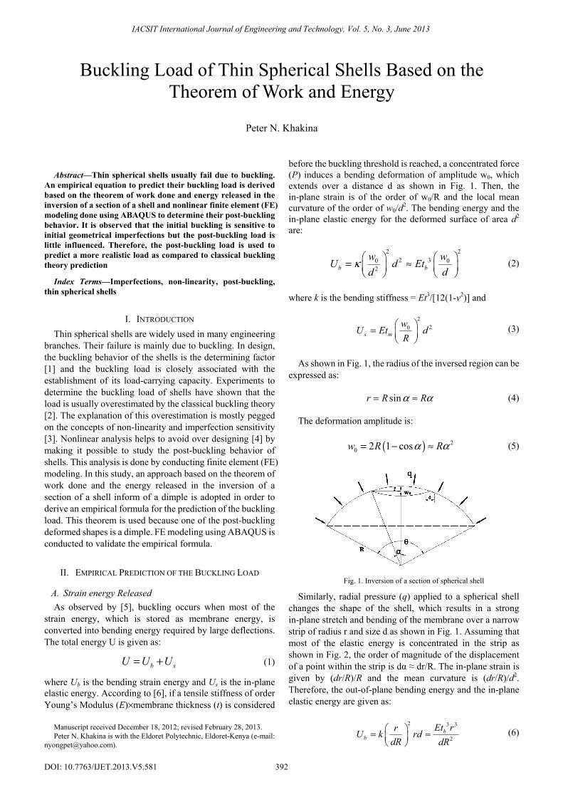
As shown in Fig. 1, the radius of the inversed region can be expressed as:
sinr R Rα α= ≈ (4)
The deformation amplitude is:
( ) 20 2 1 cosw R Rα α= − ≈ (5)
Fig. 1. Inversion of a section of spherical shell
Similarly, radial pressure (q) applied to a spherical shell changes the shape of the shell, which results in a strong in-plane stretch and bending of the membrane over a narrow strip of radius r and size d as shown in Fig. 1. Assuming that most of the elastic energy is concentrated in the strip as shown in Fig. 2, the order of magnitude of the displacement of a point within the strip is dα ≈ dr/R. The in-plane strain is given by (dr/R)/R and the mean curvature is (dr/R)/d2. Therefore, the out-of-plane bending energy and the in-plane elastic energy are given as:
2 3 3
2b
bEt rrU k rd
dR dR⎛ ⎞= ≈⎜ ⎟⎝ ⎠
(6)
Buckling Load of Thin Spherical Shells Based on the Theorem of Work and Energy
Peter N. Khakina
IACSIT International Journal of Engineering and Technology, Vol. 5, No. 3, June 2013
392DOI: 10.7763/IJET.2013.V5.581

and 2 3 3
2 4m
sEt r drdU Et rd
R R⎛ ⎞= =⎜ ⎟⎝ ⎠
(7)
Therefore:
3 3 3 3
2 4b mEt r Et r d
UdR R
= + (8)
According to Holst and Calladine [7], Energy released in the inversion of a section of a spherical shell by a radial force is given by:
2.5 1.50Et wU
R= (9)
It can therefore be assumed that Eq. (8) and Eq. (9) are equal.
Fig. 2. Strain energy magnitude concentration.
B. Work Done in the Inversion of the Shell A force (F) does work (W) when the body undergoes a
displacement (x) in the direction of the force. Thus, work can be expressed as:
0
rW Fdx= ∫ (10)
Pressure (q) is force per unit area (A):
FqA
= (11)
Substituting for F in Eq. (9):
0 0
r rW qAdx qdV= =∫ ∫ (12)
Therefore:
20 03
6 2q w wW Rπ ⎛ ⎞= −⎜ ⎟
⎝ ⎠ (13)
C. Application of Theorem of Work and Energy According to the theorem of work done and energy
released, the work done in the inversion of the shell is the same as the strain energy released [8]. Therefore:
2 2.5 1.50 0 03
6 2q w w Et w
RR
π ⎛ ⎞− =⎜ ⎟⎝ ⎠
(14)
Substituting Eq. (4) and Eq. (5) into Eq. (14) and solving for q:
( )2.5
2
126
tq ERπα α
⎛ ⎞= ⎜ ⎟− ⎝ ⎠ (15)
The buckling load can now be finalized as:
2.5tq CER
⎛ ⎞= ⎜ ⎟⎝ ⎠
(16)
where:
( )2
126
Cπα α
=−
(17)
α is the angle subtended by the inversed region to the center. The value of C that is given by [9] who based their derivation on post-buckling load is used to give a more realistic buckling load.
III. NON-LINEAR FINITE ELEMENT (FE) MODELING The post-buckling behavior of thin spherical shells was
investigated by conducting FE modeling using ABAQUS. Several thin spherical shells made from mild steel of E = 206 × 109 N/m2, fixed along the boundary, meshed with triangular shell elements-S3R [10] and subjected to uniform radial pressure were modeled. To facilitate the non-linear FE modeling, an initial geometrical imperfection in the form of a dimple was introduced. Riks method was used to trace the load-deflection curves, which are shown in Fig. 3. The summary of the buckling load obtained from the empirical formula that is the same as the average post-buckling load from the load-deflection curves is shown in Table I.
0.0 0.1 0.2 0.3 0.40
50
100
150
200
250
LOA
D (k
N/m
2 )
DEFLECTION (m)
imp=t imp=2t imp=3t
a) L = 30m, f = 3m, R = 39m and t = 0.04m
0.00 0.05 0.10 0.15 0.20 0.25 0.30 0.350
50
100
150
200
250
LOA
D (k
N/m
2 )
DEFLECTION (m)
imp=t imp=2t imp=3t
b) L = 20m, f = 2.5m, R = 21.25m and t = 0.02m.
IACSIT International Journal of Engineering and Technology, Vol. 5, No. 3, June 2013
393

0.0 0.1 0.2 0.3 0.4 0.5 0.6 0.7 0.80
50
100
150
200
250
LOA
D (k
N/m
2 )
DEFLECTION (m)
imp=2t imp=3t imp=4t
c) L = 20m, f = 2.5m, R = 21.25m and t = 0.03m
0.00 0.05 0.10 0.15 0.20 0.25 0.30 0.350
5
10
15
20
25
30
LOA
D (k
N/m
2 )
DEFLECTION (m)
imp=t imp=2t imp=3t
d) L = 20m, f = 1m, R = 50.5m and t = 0.02m.
Fig. 3. Load deflection curves for different shells.
TABLE I: VALUES OF THE BUCKLING LOAD FOR VARIOUS SHELLS
Shell Geometrical parameters in m. Buckling load by the derived
formula (kN/m2) Classical buckling theory load
(kN/m2) Derived formula value Percentage (%) of
Classical load L f t
1 20 2.5 0.03 55 497 11 2 30 3.0 0.04 36 262 14 3 20 2.5 0.02 30 221 13 4 20 1.0 0.02 5.4 39 14
IV. DISCUSSION AND VALIDATION OF THE BUCKLING LOAD It is observed from the load-deflection curves that the
initial buckling of the shells is sensitive to the initial geometrical imperfection but the post-buckling load is little influenced by the initial geometrical imperfections because the curves tend to meet at the ‘plateau’ load. The empirical prediction shows that the buckling load for spherical shells is proportional to t2.5. This is further proved by [11] in their study of determining a reduction factor of the classical buckling load if the t0.5 in that factor is taken out and multiplied by the t2 in the formula. Theoretical studies about the buckling load and experimental results by other researchers range approximately from 7 to 67% of the classical buckling as mentioned by [12], [13].
The empirical formula derived gives a buckling load, which ranges between 11% - 14% of the classical buckling load depending on the geometrical parameters used. This prediction is within the range of theoretical predictions and experiments by other researchers. This shows that the empirical formula that is derived in this study is valid.
V. CONCLUSIONS The theorem of work done and energy released in the
inversion of a section of the shell is used to derive an empirical equation for the buckling load. FE modeling is done to identify the post-buckling behavior. It is observed from the load-deflection curves that the curves form a ‘plateau’ at the post-buckling load. This load is used to predict the buckling load, which is validated by FE modeling. The results of this equation correlate closely with results obtained both theoretically and experimentally from previous
studies. Further work can be done to extend this empirical formula to predict the buckling load of single-layer reticulated shells using the continuum analogy method.
REFERENCES [1] I. M. Kani and R. E. McConnel, “The analysis and testing of a
single-layer shallow braced dome,” in Proc. IASS Symposium on Membrane Structures and Space Frames, Osaka, Japan, September 15-19, 1986, pp. 105-112.
[2] E. C. Zhu, Z. W. Guan, P. D. Rodd, and D. J. Pope, “Buckling of oriented strand board webbed wood I-Joists,” Journal of Structural Engineering, vol. 131, no. 10, pp. 1629-1636, 2005.
[3] E. Zhu, P. Mandal, and C. R. Calladine, “Buckling of thin cylindrical shells: An attempt to resolve a Paradox,” International Journal of Mechanical Sciences, vol. 44, pp. 1583-1601, 2002.
[4] 3D CAD Design Software SolidWorks. [Online]. Available: http://www.solidworks.com
[5] G. Forasassi and R. L. Frano, “Curved thin shell buckling behavior,” Journal of Achievements in Materials and Manufacturing Engineering, vol. 23, no. 2, pp. 55-58, 2007.
[6] E. Helfer, S. Harlepp, L. Bourdieu, J. Robert, F. C. MacKintosh, and D. Chatenay, “Buckling of actin-coated membranes under application of a local force,” Physical review letters, vol. 87, no. 8, pp. 1-4, 2001.
[7] J. M. F. G. Holst and C. R. Calladine, “Inversion problems in elastic thin shells,” European Journal of Mechanics, vol. 13, pp. 3-18, 1994.
[8] L. Xifu, Z. Tao, and Z. Chunxiang, Theoretical Mechanics, Harbin: Institute of Technology Press, 2007.
[9] P. N. Khakina, M. I. Ali, E. N. Zhu, H. Z. Zhou, and B. H. Moula, “Effect of the rise/span ratio of a spherical cap shell on the buckling load ,” World Academy of Science, Engineering and Technology, vol. 80, pp. 446-452, 2011.
[10] ABAQUS Theory Manual, version 6.1. Hibbitt, Karlsson, and Sorensen, Providence, RI, 2000.
[11] P. N. Khakina and H. Zhou, “A reduction factor for buckling load of spherical cap shells,” Research Journal of Applied Sciences, Engineering and Technology, vol. 3, pp. 1439-1442, 2011.
[12] C. Y. Chia, “Buckling of Thin Spherical Shells,” Ingenieur-Archiv, vol. 40, pp. 227-237, 1971.
[13] L. R. Carlson, R. L. Sendelbeck, and N. J. Hoff, “Experimental studies of the buckling of complete spherical shells,” Experimental Mechanics, vol. 1, pp. 281-288, 1966.
IACSIT International Journal of Engineering and Technology, Vol. 5, No. 3, June 2013
394