"bu \ "tu
TRANSCRIPT

United States Patent 1191 Mansfield et al.
5,014,192 May 7, 1991
Patent Number:
Date of Patent: [11]
[45]
[54]
[75]
173]
[2 1] [22]
[63]
[51] [52]
[58]
[56]
SYSTEM FOR LOCATING A FILE IN A LOGICAL RING BY SEQUENTIALLY FORWARDING ACCESS REQUEST WITH FILE SYSTEM NAME AND FILE NAME
Inventors: Bruce M. Mans?eld, Kent, Wash; Frank C. Kolnick; Andrew I. Kun, both of Willowdale, Canada
Assignee: Motorola Computer X, Inc., Kent, Wash.
Appl. No.: 300,687
Filed: Jan. 19, 1989
Related US. Application Data
Continuation of Ser. No. 110,614, Oct. 19, 1987, aban doned, which is a continuation of Ser. No. 730,929, May 6, 1985, abandoned.
4,682,326 7/19B7 Ulug . . . . . . . . . . . . . . . . . . . . . .. 370/89
4,698,629 10/1987 Mori et al. ................... .. IMO/825.05
OTHER PUBLICATIONS
Ebrahimi et al. “File Name Mapping Method Permit ting Network Location Transparency", IBM TDB vol. 26, No. 7B, Dec. 1983, pp. 3791-3794. IEE Proceedings, vol. 131, No. 2 Part E, Section A-I, Mar. 1984, pp. 38-44, Old Woking, Surrey, 0.8., R. Hull et al., "Virtual Resource Ring". The 1st Int'l Conf. on Computer Communication, Washington, 24th-26th Oct. 1972, pp. 364-370, A.C.M., N.Y., D. J. Farber et al., “The Structure of a Distrib uted Computer System”.
Primary Examiner-Thomas C. Lee Attorney. Agent. or Firm—Walter W. Nielsen
[57] ABSTRACT
111:. C1; ............................................. .. G061 13/42 A data management system used by a digital computer us. c1. ............................... .. 364/200; 364/240.8; System comprises a plurality of individual ?le systems
364/241.1; 364/222.81; 364/284.4; IMO/825.05; which are connected together in a logical n'ng con?gu 370/355 ration around which ?le requests travel. File requests
Field of Search 364/200 MS File, 900 MS File; 340/82105, 825.50; 370/85.4, 85.5, 94.1
References Cited
U.S. PATENT DOCUMENTS
may be transmitted by the user to the "next" ?le system in the ring relative to the user.
File requests optionally may or may not specify a ?le system name. If a ?le system name is speci?ed, then the request is forwarded unidirectionally around the logical
4,366,479 12/1982 Mori et al. ................... .. 340/825.05 ring until either that ?le system name is found or the 4,477,381 10/1984 Kobayashi et al. ........... .. 364/900 request returns to its starting point_ If no ?le system
1123-223 3/ 13°19‘ ‘11 3403/(i25égg name is speci?ed, then an attempt is made to satisfy the 4:590:468 551986 ago X request on tea-011d ?le srystern in turn until teither the ‘re 4,612.541 9/1986 0111115111 ........................ .. IMO/825.05 qufist '5 Sam "3 or I '3 request ‘mm o “8 Stamng
4,644,468 2/1987 Doster et a]. 304/200 POM 4,644,470 2/1987 Feigenbaum et al. .... .. 364/200 4,049,535 3/1987 Ulug ................................ .. 370/89 X 8 Claims, 6 Drawing Sheets
\ FILE 505 FILE SYSTEM -—-——-—-~ SYSTEM
11 I: II I
5 r306 F'
SEARCH DIRECTION
310 FILE 312 * FILE \
SYSTEM ~——-—- SYSTEM -—?
"Bu \ "Tu (
302 USER “ 500

US. Patent May 7, 1991 Sheet 1 of 6 5,014,192
um 51 W 3 z 53 55 \ con-mama
' I
ICM —50 1014 "52 1 54 5 Ian I 1 \ ___ 1
mm 1( D I 1 2°"!
/CBLL 1 ‘cam. a‘ 21” NIM 2 7 _
4 cam. n PRjJCESSOR —PROCESSOR ‘ 24 _ \
FIG 2 7\ RAM "ROM 27 - ' 2s’ 30" 2s
29\ BUS INTERFACE 43 42 4+
\ ~40
I J

US. Patent May 7, 1991 Sheet 2 of 6 5,014,192
m1 @ m “* so \
s1 @ m3 m5 m6 \
VIRTUAL MACHINE 63 \_ PROCESSOR PROCESSOR PROCESSOR PROCESSOR PROCESSOR pnoccsson
1 ‘ 2 a 4 5 s
\71 7? 75’ 7+’ 75/ 76)
982983 85
FIG. 3
FIG-4

US. Patent May 7, 1991 Sheet 3 of 6 5,014,192
'USER‘ PROCESS DATA "105
READ 106 104
107 DEVICE MANAGER
(EESP)
10f5 \- INTERRUPT /
‘VIRTUAL MACHINE ~61
102~I 101 DEVICE "

US. Patent May 7, 1991 Sheet 4 of 6 5,014,192
APPLICATIONS
1 1 1 ‘ k15s. PLAIN RELATIONAL USER-DEFINED
} 1 ‘, H54 FlLE MANAGEMENT
I H50 DISK MANAGEMENT |
‘, L151 VIRTUAL DISKS
‘ k152
PHYSICAL DISK DEWCES
- H55
FIG- '7

US. Patent May 7, 1991 Sheet 5 of 6 5,014,192
zc'runn 'n'
ICTURB ‘A’ I 175 P 174 I ,171 \
\\ '\ \ 170
\
\\\ \\\ 'I '1 \\\\ \\\ [III ”/
\\ ‘\\ I I \\ I’ I
x I I \ I I
1 176 177 r
175
SCREEN ‘1 '
APPLICATIONS
‘ *202 1-203 _ \150 182
20‘ DISPLAY FORM IJ ‘ ~213
20431181 ~2D5 (184 PICTURE
\ 20s
2") 18a wINItaow 212 211 1816 207 _1 I
VIRTUAL INPUT DEVICE VIRTUAL OUTPUT DEvICE
205% 209,-, k157' PHYSICAL DEvICEs
k18s FIG. 10

US. Patent May 7, 1991 Sheet 6 of 6 5,014,192
FILE FILE 505“ FILE sYFgFM ———- SEGIFM -——-* SIIFFTFM
l ~304 “306 7
SEARCH DIRECTION
FILE 312" FILE 310* FILE SYSTEM — SYSTEM SYSTEM
"Bl! llTll IIN"
s62 USER “500
329
FORWARD REQU EST TO NEXT
FILE SYSTEM
REPLY TO WRAP“ USER WITH AROUND
'5‘
323 NO
FILE SYSTEM‘
524 MARK REQUEST FOR
SPECIFIER WRAP_ AROUND
N L o ATTEMPT _ 528}
T0 SATISFY 325 REQUEST 330
REPLY TO USER WITH ERROR

5,014,192 1
SYSTEM FOR LOCATING A FILE IN A LOGICAL RING BY SEQUENTIALLY FORWARDING
ACCESS REQUEST WITH FILE SYSTEM NAME AND FILE NAME
RELATED INVENTIONS
This application is a continuation of prior application Ser. No. 110,614, ?led Oct. 19, 1987, now abandoned which is a continuation of Ser. No. 730,929, ?led May 6, I985, now abandoned. The present invention is related to the following
inventions, ?led on even date herewith, all assigned to the assignee of the present invention: 1. Title: Nested Contexts in a Virtual Single Machine; Inventors: Andrew Kun, Frank Kolnich and Bruce Mans?eld
Ser. No.: 730,903 (now abandoned) and Ser. No. 270,437, ?led ll/07/88, now abandoned. Title: Network Interface Module With Minimized Data Paths; Inventors: Bernard Weisshaar and Mi chael Barnea; Ser. No.: 730,621, now US. Pat. No. 4,754,395.
. Title: Method of Inter-Process Communication in a Distributed Data Processing System; Inventors: Ber nard Weisshaar, Frank Kolnick, Andrew Run, and Bruce Mans?eld; Ser. No.: 730,892, now US. Pat. No. 4,694,396.
. Title: Logical Ring in a Virtual Single Machine; Inventors: Andrew Kun, Frank Kolnick and Bruce Mans?eld; Ser. No.: 730,923 (now abandoned) and Ser. No. l83,469, ?led 4/ 15/88 (continuation).
. Title: Virtual Single Machine With Message-Like Hardware Interrupts and Processor Exceptions; In ventor: Andrew Kun; Ser. No.: 730,922.
TECHNICAL FIELD
This invention relates generally to digital data pro cessin g, and. in particular, to a data management system comprising a plurality of ?le systems coupled in a logi cal ring.
BACKGROUND OF THE INVENTION
The present invention concerns a distributed data processing system-that is, two or more data processing systems which are capable of functioning independently but which are so coupled as to send and receive mes sages to and from one another. A Local Area Network (LAN) is an example of a
distributed data processing system. A typical LAN comprises a number of autonomous data processing "cells”, each comprising at least a processor and mem ory. Each cell is capable of conducting data processing operations independently. In addition, each cell is cou pled (by appropriate means such as a twisted wire pair, coaxial cable, ?ber optic cable, etc.) to a network of other cells which may be, for example, a loop, star, tree, etc., depending upon the design considerations. As mentioned above, the present invention ?nds util
ity in such a distributed data processing system, since there is a need in such a system for the processes which are executing or to be executed in the individual cells to share data and to communicate data among themselves.
Information may be thought of as being stored in the form of ?les in one or more “?le systems“. A ?le system is a way of logically organizing data, and it may com prise one or more physical data storage devices. Usu ally, a ?le system comprises an organized arrangement
2.
0
35
40
45
50
55
60
65
2 of data and a ?le index identifying the data, its location, and perhaps other characteristics.
In the present invention, any of the individual cells of a LAN may contain one or more ?le systems. Certain ?le systems may be unique, while other ?le systems may be copies in order to provide a degree of redundancy. There is an urgent need in certain distributed data ‘
processing systems to provide “data access transpar ency". Data access transparency is de?ned herein to mean that any ?le can be accessed by any process lo cated anywhere in the distributed data processing sys tem. .
There is also an urgent need regarding certain of such distributed data processing systems to provide “data residence transparency". Data residence transparency is de?ned herein to mean that any file can be accessed wherever it may reside, even if it has been physically moved within the system.
BRIEF SUMMARY OF INVENTION
Accordingly, it is an object of the present invention to provide an improved data management system within a distributed data processing system.
It is also an object of the present invention to provide a distributed data processing system having a data man agement system with data access transparency.
It is a further object of the present invention to pro vide a distributed data processing system having a data management system with data residence transparency. These and other objects are achieved in accordance
with a preferred embodiment of the invention by pro viding a data management system for use in a data pro cessing system, the data management system compris ing a plurality of individual ?le systems, means for cou pling the ?le systems together, means for generating an access request to one of the ?le systems. and means for attempting to satisfy the access request by accessing successive ?le systems until either the access request is satis?ed or until all of the ?le systems have been ac cessed.
BRIEF DESCRIPTION OF THE DRAWINGS
The invention is pointed out with particularity in the appended claims. However, other features of the inven tion will become more apparent and the invention will be best understood by referring to the following de tailed description in conjunction with the accompany ing drawings in which:
FIG. I shows a representational illustration of a sin gle network, distributed data processing system incor porating the improved data management system of the present invention. FIG. 2 shows a block diagram illustrating a multiple
network, distributed data processing system incorporat ing the improved data management system of the pres ent invention. FIG. 3 shows an architectural model of a data pro
cessing system incorporating the present invention. FIG. 4 shows the relationship between software con
texts and processes as they relate to the present inven tion.
FIG. 5 shows the relationship between external events and processes. FIG. 6 shows how messages may be sent between
processes within nested contexts.
5,014,192 3
FIG. 7 shows an architectural model of the improved data management system incorporating the present in vention.
FIG. 8 shows an architectural software model of the improved data management system incorporating the present invention. FIG. 9 shows the relationship between pictures,
views, and windows in the human interface of a data processing system incorporating the present invention. FIG. 10 shows a conceptual view of the different
levels of human interface within a data processing sys tem incorporating the present invention. FIG. 11 shows a block diagram of a logical ring of ?le
systems, illustrating how an access request to a ?le system is handled by the present invention. FIG. 12 shows a flow diagram illustrating the opera
tion of the improved data management system of the present invention.
OVERVIEW OF COMPUTER SYSTEM
With reference to FIG. 1, a distributed computer con?guration is shown comprising multiple cells 2-7 (nodes) loosely coupled by a local area network (LAN) 1. The number of cells which may be connected to the network is arbitrary and depends upon the user applica tion. Each cell comprises at least a processor and mem ory, as will be discussed in greater detail with reference to FIG. 2 below. In addition, each cell may also include other units, such as a printer 8, operator display module (ODM) 9, mass memory module 13, and other I/O device 10. With reference now to FIG. 2, a multiple-network
distributed computer con?guration is shown. A ?rst local area network LAN 1 comprises several cells 2, 4, and 7. LAN 1 is coupled to a second local area network LAN 2 by means of an Intelligent Communications Module (ICM) 50. The Intelligent Communications Module provides a link between the LAN and other networks and/or remote processors (such as program mable controllers). LAN 2 may comprise several cells (not shown) and
may operate under the same LAN protocol as that of the present invention, or it may operate under any of several commercially available protocols, such as Ethernet; MAP, the Manufacturing Automation Proto col of General Motors Corp.; Systems Network Archi tecture (SNA) of International Business Machines, Inc.; SECS-II; etc. Each ICM 50 is programmable for carry ing out one of the above-mentioned speci?c protocols. In addition, the basic processing module of the cell itself can be used as an intelligent peripheral controller (IPC) for specialized devices. LAN 1 is additionally coupled to a third local area
network LAN 3 via ICM 52. A process controller 55 is also coupled to LAN 1 via ICM 54. A representative cell N (7, FIG. 2) comprises a pro
cessor 24 which, in a preferred embodiment, is a Motor ola 68010 processor. Each cell further includes a read only memory (ROM) 28 and a random access memory (RAM) 26. In addition, each cell includes a Network Interface Module (NIM) 21, which connects the cell to the LAN, and a Bus Interface 29, which couples the cell to additional devices within a cell. While a minimal cell is capable of supporting two peripheral devices, such as an Operator Display Module (ODM) 41 and an [/0 Module 44, additional devices (including additional processors, such as processor 27) can be provided within a cell. Other additional devices may comprise,
5
15
20
25
30
35
40
45
50
55
65
4 for example, a printer 42, and a mass-storage module 43 which supports a hard disk and a back-up device (?oppy disk or streaming tape drive). The Operator Display Module 41 provides a key
board and screen to enable an operator to input infor mation and receive visual information.
While a single cell may comprise all of the above units, in the typical user application individual cells will normally be dedicated to specialized functions. For example, one or more mass storage cells may be set up to function as data base servers. There may also be several operator consoles and at least one cell for gener ating hard-copy printed output. Either these same cells, or separate dedicated cells, may execute particular ap plication programs. The system is particularly designed to provide an
integrated solution for factory automation, data acquisi tion, and other real-time applications. As such, it in cludes a full complement of services, such as a graphical output, windows, menus, icons, dynamic displays, elec tronic mail, event recording, and ?le management. Soft ware development features include compilers, a win dow-oriented editor, a debugger, and performance monitoring tools.
Local Area Network
The local area network, as depicted in either FIG. 1 or FIG. 2, ties the entire system together and makes possible the distributed virtual machine model de scribed below. The LAN provides high throughput, guaranteed response, reliability, and low entry cost. The LAN is also autonomous, in the sense that all sys tem and applications software is unaware of its exis tence. For example, any Network Interface Module (eg. NIM 21, FIG. 2) could be replaced without rewrit ing any software other than that which directly drives it.
The LAN interconnection medium may be twisted- ‘ pair or coaxial cable. Two channels (logically, two distinct networks) may be provided for reliability and for increased throughput. The LAN architecture is a logical ring, in which an
electronic “token" is constantly passed from cell to cell at high speed. The current holder of the token may use it to send a “frame" of data or may pass it on to the next cell in the ring. The NIM only needs to know the logi cal address and status of its immediately succeeding neighbor. The NlM’s responsibility is limited to detect ing the failure of that neighbor or the inclusion of a new neighbor. In general, adjustment to failed or newly added cells is automatic. The network interface maps directly into the proces
sor‘s memory. Data exchange occurs through a dual ported buffer pool which contains a linked list of pend ing "frames". Logical messages, which vary in length, are broken into ?xed-size frames for transmission and are re-assembled by the receiving NIM. Frames are sequence-numbered for this purpose. If a frame is not acknowledged within a short period of time. it is re transmitted a number of times before being treated as a failure. As described above with reference to FIG. 2, the
LAN may be connected to other LAN‘s operating under the same LAN protocol via so-called "bridge ways“, or it may be connected to other types of LAN‘s via “gateways".
5,014,192 5
Software Model
The computer operating system of the present inven tion operates upon processes, messages, and contexts, as such terms are de?ned hereinafter in the section entitled “Virtual Machine". This operating system offers the programmer a hardware abstraction, rather than a data or control abstraction.
Processes are referenced without regard to their physical location via a small set of message-passing primitives. Every process has both a unique system generatcd identi?er and a not necessarily unique name assigned by the programmer. The identi?er provides quick direct access, while the name has a limited scope and provides symbolic, indirect access. With reference to FIG. 3, an architectural model of
the present invention is shown. The bottom, or hard ware, layer 63 comprises a number of processors 71-76, as described above. The processors 71-76 may exist physically within one or more cells. The top, or soft ware, layer 60 illustrates a number of processes P1-P1O which send messages m1-m6 to each other. The middle layer 61, labelled “virtual machine", isolates the hard ware from the software, and it allows programs to be written as if they were going to be executed on a single processor. Conversely, programs can be distributed across multiple processors without having been explic itly designed for that purpose. An important purpose of the virtual machine concept
herein-disclosed is to provide the applications program mer with a simple, consistent model in which to design his system. This model, as mentioned above, is reduced to several elemental concepts: processes, messages, and contexts, each of which will be de?ned and discussed in detail below. As a consequence of this elemental model, hardware peculiarities are made transparent to the user, and changes in hardware con?gurations have no direct effect on the software.
The Virtual Machine
A “process" is a self-contained package of data and executable procedures which operate on that data. The data is totally private and cannot be accessed by other processes. There is no concept of shared memory within the present invention. Execution of a process is strictly sequential. Multiple processes execute concur rently and must be scheduled by the operating system. The processes can be re-entrant, in which case only one copy of the code is loaded even if multiple instances are active. Every process has a unique “process identi?er num
ber" (PID) by which it can be referenced. The PID is assigned by the system when the process is created and remains in effect until the process terminates. The PID assignment contains a randomizing factor which guar antees that the PID will not be re-used in the near fu ture. The contents of the PID are irrelevant to the pro grammer but are used by the virtual machine to physi cally locate the process. A PID may be thought of as a “pointer" to a process. Every process also has a “name“ which is a variable
length string of characters assigned by the programmer. A name need not be unique, and this ambiguity may be used to add new services transparently and to aid in fault-tolerance. FIG. 4 illustrates that the system-wide name space is
partitioned into distinct subsets by means of “contexts" identi?ed by reference numerals 90-92. A context is
15
20
25
45
55
65
6 simply a collection of related processes whose names are not known outside of the context. Context 90, for example, contains processes A, a, a, b, c, d, and e. Con
- text 91 contains processes B, a, b, c, and f. And context 92 contains processes C, a, c, d, and x. One particular process in each context, called the
“context process”, is known both within the context - and within the immediately enclosing one (referred to as its "parent context”). In the example illustrated in FIG. 4, processes A-C are context processes for con texts 90-92, respectively. The parent context of context 91 is context 90, and the parent context of context 92 is context 91. conceptually, the context process is located on the boundary of the context and acts as a gate into it.
Processes inside context 92 can reference any pro cesses inside contexts 90 and 91 by name. However, processes in context 91 can only access processes in context 92 by going through the context process C. Processes in context 90 can only access processes in context 92 by going through context processes 13 and C. The function of the context process is to ?lter incom
ing messages and either reject them or reroute them to other processes in its context. Contexts may be nested, allowing a hierarchy of abstractions to be constructed. A context must reside completely on one cell. The entire system is treated as an all-encompassing context which is always present and which is the highest level in the hierarchy. In enssence, contexts de?ne localized protection domains and greatly reduce the chances of unintentional naming con?icts.
If appropriate, a process inside one context can be "connected" to one inside another context by exchang ing PlD's, once contact has been established through one or the other of the context processes. Most process servers within the present invention function that way. Initial access is by name. Once the desired function (such as a window or ?le) is “opened", the user process and the service communicate directly via PlD's. A “message" is a variable-length buffer (limited only
by the processor‘s physical memory size) which carries information between processes. A header, inaccessible to the programmer, contains the destination name and the sender's PID. By convention, the ?rst ?eld in a message is a null-terminated string which de?nes the type of message (e.g., “read“, “status“, etc.) Messages are queued to the receiving process when they are sent. Queuing ensures serial access and is used in preference to semaphores, monitors, etc.
Messages provide the mechanism by which hardware transparency is achieved. A process located anywhere in the virtual machine can send a message to any other process if it knows its name. Transparency applies with some restrictions across bridgeways (i.e., the interfaces between LAN’s operating under identical network pro tocols) and, in general, not at all across gateways (i.e., the interfaces between LAN’s operating under different network protocols) due to performance degradation. However, they could so operate, depending upon the required level of performance. With reference now to FIG. 5, the relationship of
external events to processes will now be described. The virtual machine makes devices look like processes. For example, when an interrupt occurs in an external device 101, the virtual machine kernel 61 queues an interrupt message 103 to a speci?c process 104, known as an “external event service process" (EESP). functioning as the device manager. For ef?ciency, the message is pre~ allocated once and circulates between the EESP and

5,014,192 7
the kernel. The message contains just enough informa tion to indicate the ocurrence of the event. The EESP performs all hardware-speci?c functions related to the event, such as setting control registers, moving data 105 to a user process 106, transmitting "Read" messages from the user process 106, etc., and then “releasing" the interrupt. To become an EESP, a process issues a “connect”
primitive specifying the appropriate device register(s). It must execute a “disconnect” before it exits. Device independence is achieved by making the message proto col between EESP’s and applications processes the same wherever possible.
Inter-Process Communication
All inter-process communication is via messages. Consequently, most of the virtual machine primitives are concerned with processing messages. The virtual machine kernel primitives are the following: ALLOC-requests allocation of a (message) buffer of a
given size. FREE-requests deallocation of a given message
buffer. PUT-end a message to a given destination (by name or
PID). GET-wait for and dequeue the next incoming mes
sage, optionally from a speci?c process (by PID). FORWARD-pass a received message through to an
other process. CALL-send a message, then wait for and dequeue the
reply. REPLY-send a message to the originator of a given
message. ANY_MSG—retums “true“ ifthe receive queue is not empty, else returns “false"; optionally, checks if any messages from a speci?c PlD are queued. To further described the function of the kernel primi
tives, ALLOC handles all memory allocations. It re turns a pointer to a buffer which can be used for local storage within the process or which can be sent to an other process (via PUT, etc.). ALLOC never “fails", but rather waits until enough memory is freed to satisfy the request. The PUT primitive queues a message to another pro
cess. The sending process resumes execution as soon as the message is queued. FORWARD is used to quickly reroute a message but
maintain information about the original sender (whereas PUT always makes the sending process the originator of the message). REPLY sends a message to the originator of a previ
ously received message, rather than by name or PID. CALL essentially implements remote subroutine in
vocations, causing the caller to suspend until the re ceiver executes a REPLY. Subsequently, the replied message is dequeued out of sequence, immediately upon arrival, and the caller resumes execution. The emphasis is on concurrency, so that as many
processes as possible are executed in parallel. Hence neither PUT nor FORWARD waits for the message to be delivered. Conversely, GETS suspends a process until a message arrives and dequeues it in one operation. The ANY_MSG primitive is provided so that a process may determine whether there is anything of interest in the queue before committing itself to a GET. When a message is sent by name, the destination
process must be found in the name space. The search path is determined by the nesting of the contexts in
15
20
25
30
35
45
50
55
60
65
8 which the sending process resides. From a given pro cess, a message can be sent to all processes in its own context or (optionally) to those in any higher context. Refer to FIG. 6. The contexts are searched from the current one upward until a match is found or until the system context is reached. All processes with the same name in that context are then queued a copy of the - message. For example, with reference to FIG. 6, assume that in
context 141 process y sends a message to ALL pro cesses by the name it. Process y ?rst searches within its own context 141 but ?nds no process it. The process y searches within the next higher context 131 (its parent context) but again ?nds no process x. Then process y searches within the next higher context 110 and finds a process x, identi?ed by reference numeral 112. Since it is the only process x in context 110, it is the only recipi ent of the message from process y.
If process a in context 131 sends a message to ALL processes by the name x, it ?rst searches within its own context 131 and, finding no processes x there; it then searches within context 110 and finds process it. Assume that process b in context 131 sends a message
to ALL processes by the name A. It would ?nd process A (111) in context 110, as well as process A (122) which is the context process for context 121. A process may also send a message to itself or to its
context process without knowing either name explic itly. The concept of a “logical ring" (analogous to a LAN)
allows a message to be sent to the NEXT process in the system with a given name. The message goes to exactly one process in the sender's context, if such a process exists. Otherwise the parent context is searched. The virtual machine guarantees that each NEXT
transmission will reach a different process and that eventually a transmission will be sent to the logically “?rst" process (the one that sent the original message) in the ring, completing the loop. In other words, all processes with the same name at the same level can communicate with each other without knowing how many there are or where they are located. The logical ring is essential for distributing services such as a data base. The ordering of processes in the ring is not pre dictable.
For example, if process a (125) in context 121 sends a message to process a using the NEXT primitive, the search finds a ?rst process a (124) in the same context 121. Process a (124) is marked as having received the message, and then process a (124) sends the message on to the NEXT process a (123) in context 121. Process a (123) is marked as having received the message, and then it sends the message on to the NEXT process a, which is the original sender process a (125), which knows not to send it further on, since it‘s been marked as having already received the message.
Sending messages directly by PID obviates the need for a name search and ignores context boundaries. This is known as the DIRECT mode of transmission and is the most ef?cient. For example, process A (111) sends a message in the DIRECT mode to process y in context 141.
Ifa process sends a message in the LOCAL transmis sion mode, it sends it only to a process having the given name in the sender's own context.
In summary, including the DIRECT transmission mode, there are ?ve transmission modes which can be

5,014,192 9
used with the PUT, FORWARD, and CALL primi
ALL-to all processes with the given name in the ?rst context which contains that name, starting with the sender’s context and searching upwards through all parent contexts.
LOCAL—to all processes with the given name in the sender’s context only.
NEXT-to the next process with the given name in the same context as the sender, if any; otherwise it searches upwards through all parent contexts until the name is found.
LEVEL-sends to “self’ (the sending process) or to “context” (the context process corresponding to the sender's context); "self" cannot be used with CALL primitive.
DIRECT -sent by PID. Messages are usually transmitted by queueing a
pointer to the buffer containing the message. A message is only copied when there are multiple destinations or when the destination is on another cell.
Operating System The operating system of the present invention con
sists of a kernel, which implements the primitives de scribed above, plus a set of processes which provide process creation and termination, time management (set time, set alarm, etc.) and which perform cell start-up and con?guration. Drivers for devices are also imple mented as processes (EESP's), as described above. This allows both system services and device drivers to be added or replaced easily. The operating system also supports swapping and paging, although both are invisi ble to applications software.
Unlike known distributed computer systems, that of the present invention does not use a distinct “name server" process to resolve names. Name searching is con?ned to the kernel, which has the advantage of being much faster. A minimal bootstrap program resides permanently (in
ROM) on every cell, e.g. ROM 28 in cell N of FIG. 2. The bootstrap program executes automatically when a cell is powered up and begins by performing basic on~ board diagnostics. It then attempts to find and start an initial system code module which comprises the entire kernel, and EESP’s for the clock, disk (if required), and NIM (if required). The module is sought on the ?rst disk drive on the cell, if any. lf there isn't a disk, and the cell is on the LAN, a message will be sent out request ing the module. Failing that, the required software must be resident in ROM. System services for the clock and for process creation, an initialization program, and a minimal ?le system, are also built into the module. The initialization program sets up all of the kemel‘s internal tables and then calls prede?ned entry points in each of the preloaded services (?le management, etc.). The net result is that EESP‘s for the attached devices are sched uled to run, and the cell is available.
in general, there exists a template ?le describing the initial software and hardware for each cell in the sys tem. The template de?nes a set of initial processes (usu~ ally one per service) which are scheduled immediately after the cell start-up. These processes then start up their respective subsystems. A cell con?guration ser vice on each cell sends con?guration messages to each subsystem when it is being initialized, informing it ofthe devices it owns. Thereafter, similar messages are sent
30
35
40
45
55
60
65
10 whenever a new device is added to the cell or a device fails or is removed from the cell. Thus there is no well-de?ned meaning for "system
up” or “system down"—as long as any cell is active, the system as a whole may be considered to be “up". Cells can be shut down or started up dynamically without affecting other cells on the network. The same principle applies, in a limited sense, to peripherals. Devices which can identify themselves with regard to type, model number, etc. can be added or removed without operator intervention. The operating system cannot maintain a global status of the system, nor does it attempt to cen tralize control of the entire system.
Data Management The present invention allows the user to store and
retrieve data at several levels of abstraction. At various levels it provides device-independence, transparency, multiple views of the same data and support for transac tion processing. Transparency means that a process need not know where a ?le is stored in order to access it. It also means that the ?le can be moved to another device without affecting the process. Only as many levels as are required for a particular application need be included in the system.
Referring now to FIG. 7, the lowest level of data management is the physical disk layer 153, which is completely hidden from all applications software 155. Immediately above this level are virtual disks 152 which de?ne an interface in terms of linear arrays of 1K blocks, regardless of the actual medium. Although the usual medium is disk, RAM may also be used (for tem porary ?les) to improve performance. Three types of messages are supported at this level: “initial", to format the virtual disk, and “read" and “write” to access spe ci?c blocks. The third level, disk management 151, organizes data
within a virtual disk by means ofindices. A disk index is a ?le at this level and is viewed as an extensible linear ’ array of bytes. Messages are accepted to initialize the disk, allocate and delete indices, and read and. write indices. The later two functions operate starting at a given byte offset for a given byte length. An index is automatically extended when a request references a location outside the current limits. Physical storage is allocated only when data is actually written. Optional data caching is supported at the disk management level on a per cell basis.
File management 150 is layered on top of disk man agement 151 and introduces the concept of a "?le sys tem“. A ?le system is a collection of named ?les (or named indices, in terms of the disk management layer 151). The name space constitutes a flat (single-level) directory which is allocated when the ?le system is initialized. A name may be up to 64 characters long and is hashed into the directory. Unnamed ?les are useful for building complex disk structures which are logically linked to each other, such as a hierarchical ?le directory or a database, or for temporary ?les which only the creator will use. '
Transparency is supported only at the ?le manage ment level 150 and above. It is used by simply omitting the ?le system name from the request (NEW, DE LETE, RENAME, or OPEN). In this case, the request is forwarded through all ?le systems until the given ?le name is found. The highest level 154 of data management deals in
terms of “metaphors“, which implement application

5,014,192 11
speci?c views of the data. A relational database is one example of a metaphor. Complex operations such as multi-user synchronization and record- or ?eld-locking may be implemented at this level. The present invention supports two built-in views of the data: “plain“ ?les, which are super?cially equivalent to UNIX TM ?les, and a relational database. FIG. 8 illustrates the design of the data management
software up to the plain-?le level. Each active (mounted) ?le system 165 is represented by a ?le man agement context 160. The set of all such contexts forms a logical ring for purposes of message transmission; in other words, they all have the same name (“file._mgt"). The actual name of the ?le system (stored on the disk 166 at initialization) is known only to the context pro cess.
In the plain-?le metaphor, there is exactly one pro cess for each open ?le, acting as a server for that ?le. That process (an instance of “?l__access") can be lo cated in the appropriate file management context, or any application can create its own private copy of the process. The process allows standard ?le management functions (NEW, DELETE, RENAME, OPEN, and CLOSE) plus SEEK, LOCK (lock the entire ?le against access by processes other than the owner) and UNLOCK. Note that a given ?le process is only opened once, by its owner. If not locked, any other processes which know its name or PID can read and write the ?le. Protection is provided through normal process name scoping. Protection via passwords or a similar mecha nism are in general unsupported unless supported by, another metaphor.
Human Interface
The human interface (HI) of the present invention provides a set of tools with which an end user can con struct a package speci?c to his applications require ments. Such a package is referred to as a “metaphor", since it re?ects the user’s particular view of the system. Multiple metaphors can be supported concurrently. One representative metaphor is, for example, a software development environment. The purpose of the HI metaphor is to allow consis
tent, integrated access to the data and functions avail able in the system. Since user’s perceptions of the sys tem are based largely on the way they interact with it, it is important to provide an interface with which they feel comfortable. The HI allows a systems designer to create a model consisting of objects that are familiar to the end user and a set of actions that can be applied to them. The fundamental concept of the H] is that of the
“picture". All visually-oriented information, regardless of interpretation, is represented by pictures. A picture (such as a diagram, report, menu, icon, etc.) is de?ned in a device-independent format which is recognized and manipulated by all programs in the HI and all programs using the HI. it consists of "picture elements“, such as "line”, "are", and “text”, which can be stored com pactly and transferred ef?ciently between processes. All elements have common attributes like color and ?ll pattern. Most also have type-speci?c attributes, such as typeface and style for text. Pictures are drawn in a large "world" co-ordinate system composed of "virtual pix els".
Because all data is in the form of pictures, segments of data can be freely copied between applications, e.g., from a live display to a word processor. No intermedi
25
45
55
60
65
12 ate format or conversion is required. One consequence of this is that the end user or original equipment manu facturer (OEM) has complete ?exibility in de?ning the formats of windows, menus, icons, error messages, help pages, etc. All such pictures are stored in a library rather than being built into the software and so are changeable at any time without reprogramming. A - comprehensive editor is available to define and modify pictures on-line.
All interaction with the user's environment is through either “virtual input” or “virtual output“ de vices. A virtual input device accepts keyboards, mice, light pens, analog dials, pushbuttons, etc. and translates them into text, cursor-positioning, action, dial, switch, and number messages. All physical input devices must map into this set of standard messages. Only one pro cess, an input manager for the speci?c device, is respon sible for performing the translation. Other processes can then deal with the input without being dependent on its source.
Similarly, a virtual output manager translates stan dard output messages to the physical representation appropriate to a speci?c device (screen, printer, plotter, etc.) A picture drawn on any terminal or by a process can be displayed or printed on any device, subject to the physical limitations of that device. With reference to FIG. 9, two “pictures" are illus
trated-picture A (170) and picture B (174). The concept of a “view" is used to map a particular
rectangular area of a picture to a particular device. In FIG. 9, picture A is illustrated as containing at least one view 171, and picture B contains at least one view 175. Views can be used, for example, to partition a screen for multiple applications or to extract page~sized subsets of a picture for printing.
If the view appears on a screen it is contained in a “window". With reference again to FIG. 9, view 171 of picture A is mapped to screen 176 as window 177, and view 175 of picture B is mapped as window 178. The HI allows the user to dynamically change the
size of the window, move the window around on the screen, and move the picture under the window to view different parts of it (i.e., scroll in any direction). If a picture which is mapped to one or more windows changes, all affected views of that picture on all screens are automatically updated. There is no logical limit to the number or sizes of windows on a particular screen. Since the system is distributed, it's natural for pictures and windows to be on different cells. For example, several alarm displays can share a single, common pic ture.
The primary mechanism for interacting with the HI is to move the cursor to the desired object and “select" it by pressing a key or button. An action may be per formed automatically upon selection or by further inter action, often using menus. For example, selecting an icon usually activates the corresponding application immediately. Selecting a piece of text is often followed by selection of a command such as "cut" or “under line“. Actions can be dynamically mapped to function keys on a keyboard so that pressing a key is equivalent to selecting an icon or a menu item. A given set of cursors (the cursor changes as it moves from one appli cation picture to another), windows, menus, icons. and function keys de?ne a “metaphor“. The HI builds on the above concepts to provide a set
of distributed services. These include electronic mail, which allows two or more users at different terminals to

5,014,192 13
communicate with each other in real time or to queue ?les for later delivery, and a forms manager for data entry. A subclass of windows called “virtual terminals" provides emulation of standard commercially available terminals. FIG. 10 shows the different levels of the HI and data
?ow through them. Arrows 201~209 indicate the most common paths, while arrows 210-213 indicate addi tional paths. The interface can be con?gured to leave out unneeded layers for customized applications. The philosophy behind the HI design dictates one process per object. That is, a process is created for each active window, picture, input or output device, etc. As a re sult, the processes are simpli?ed and can be distributed across cells almost arbitrarily.
Error Management An error management service is provided to catch
errors and report them to the appropriate process(es). It serves as a foundation upon which more sophisticated diagnostics and/or recovery schemes may be con structed. The system can intercept processor internal exceptions (bus and address errors, "trap" instructions, etc.), external exceptions (such as a spurious interrupts), device faults, and software-de?ned errors. The latter category is open-ended and comprises unexpected ter mination of a process, the result of a diagnostic pro gram, or in general any error detected by the kernel or by any process. Failure to ?nd the destination of a trans mitted message is one example. While internal excep tions can be associated with the particular process which caused the error, external exceptions are inde pendent, although they may directly impact one or more processes.
In summary, the prime functions of the error manage ment service are to: (l) classify and log errors, (2) gen erate notification messages, (3) accept requests to con ?gure the service and specify options, (4) accept soft ware error messages from other subsystems, and (5) terminate affected processes, if required. Item (3) above allows applications and services to indicate that they want to know about speci?c errors or classes of errors. Options include automatic logging, automatic display on the operator‘s terminal, automatic suspension (for debugging) or abortion of the offending process, and automatic dumping of the process image to a ?le. The default actions, if no options have been speci?ed, are termination, logging and display. Any outstanding re quest can be cancelled at any time. The HI logging service provides the facility to store
error messages in a chronological ?le, maintain a hard copy log, and create a dynamic display of errors, or dered by time, priority, class, etc. The debugger is often invoked upon occurrence of a process error to examine the process‘ state for clues.
DETAILED DESCRIPTION OF THE INVENTION
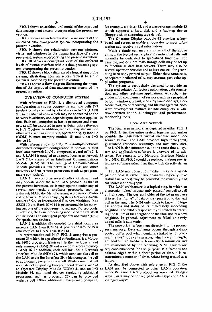
Referring now to FIG. 11, a block diagram is shown of a logical ring of ?le systems, illustrating how an access request to a ?le system is handled by the present invention. Each mounted disk volume in the distributed data processing system of the present invention consti tutes a ?le system. Each ?le system is managed by a ?le management context whose architecture is represented by FIG. 8. On a relatively large system there may be any number of active ?le systems (i.e. active ?le man agement contexts), where each ?le management context
5
20
25
35
45
55
65
14 has the name “?le._mgt”. The set of these contexts is connected together in a logical ring, as shown in FIG. 11. The name of ?le system is established when a disk
volume is initialized. The ?le system name is written into the volume header on the disk. When a ?le manage ment context starts up, it attempts to read the volume header of its associated disk. If successful, the volume name is read and becomes the name of the ?le system which that context manages. If unsuccessful, the vol ume is marked as uninitialized. Thereafter only an INI TIAL command is accepted.
Within a ?le management context, requests which reference a ?le by name (NEW, DELETE, RENAME, OPEN, and CLOSE) are sent to the context process “?le__mgt". Requests which access data (READ and WRITE) are sent directly by their PID to the disk__mgt process within the ?le management context. This PID, as well as the associated disk index, is returned in the reply to a successful NEW or OPEN command. This connects the user (e.g., a data management process) to a speci?c ?le allocation on a speci?c volume. As shown in FIG. 11, all active ?le management
contexts are viewed as forming a logical ring. Requests referencing a ?le by name are sent to the context pro cess named “?le_mgt" using transmission mode NEXT. Each context process “?le__mgt" determines whether the request is for the ?le system which it man ages, and, if it is not, it forwards the request to the next context “?le_rngt". If a request circulates the logical ring without success, then it is returned to the caller with an error indication.
In FIG. 11, assume that a user 300 (e. g. an application context) initiates a ?le access request to a certain “TEMP" ?le in ?le system “G” 306. The ?le access request is ?rst received by the “?le..mgt" context pro cess of ?le system “8" 302, which determines that the request is not for ?le system "13” and forwards it to ?le system “5" 304. Likewise, ?le system “5" 304 forwards the request on to ?le system “G" 306. The “?le__mgt" context process of ?le system “(3" 306 recognizes that the request is intended for this ?le system and then responds to user 300 that it will attempt to satisfy the request. Had the ?le access request circulated the entire loop
without success, it would have returned to user 300 with an error message. To prevent the request from recirculating the loop, once a given ?le system (e.g. ?le system "B" 302) fails to satisfy the request, it records an indication that it has attempted to satisfy this particular request, so that it doesn't reattempt to satisfy the request on any wrap-around. A ?le access request may either specify both a ?le
system name and a ?le name, or it may simply specify a ?le name. Data residence transparency is achieved by not specifying the ?le system name. Suppose, for exam ple, that user 300 doesn't know on which ?le system a desired ?le is located or doesn't care where a ?le is to be opened. In this case, an attempt is made by each succes sive “?le_mgt" context to satisfy the request of user 300. Thus the set of all disk volumes in the system may be considered one large disk space, and the user doesn’t have to know on which ?le system any given ?le is logically or physically located. For example, assume user 300 initiates a ?le access
request to a ?le "ABC” without specifying the ?le sys tem name. File system “B“ 302 will ?rst attempt to satisfy the request. However, if it's unable to. eg be

5,014,192 15
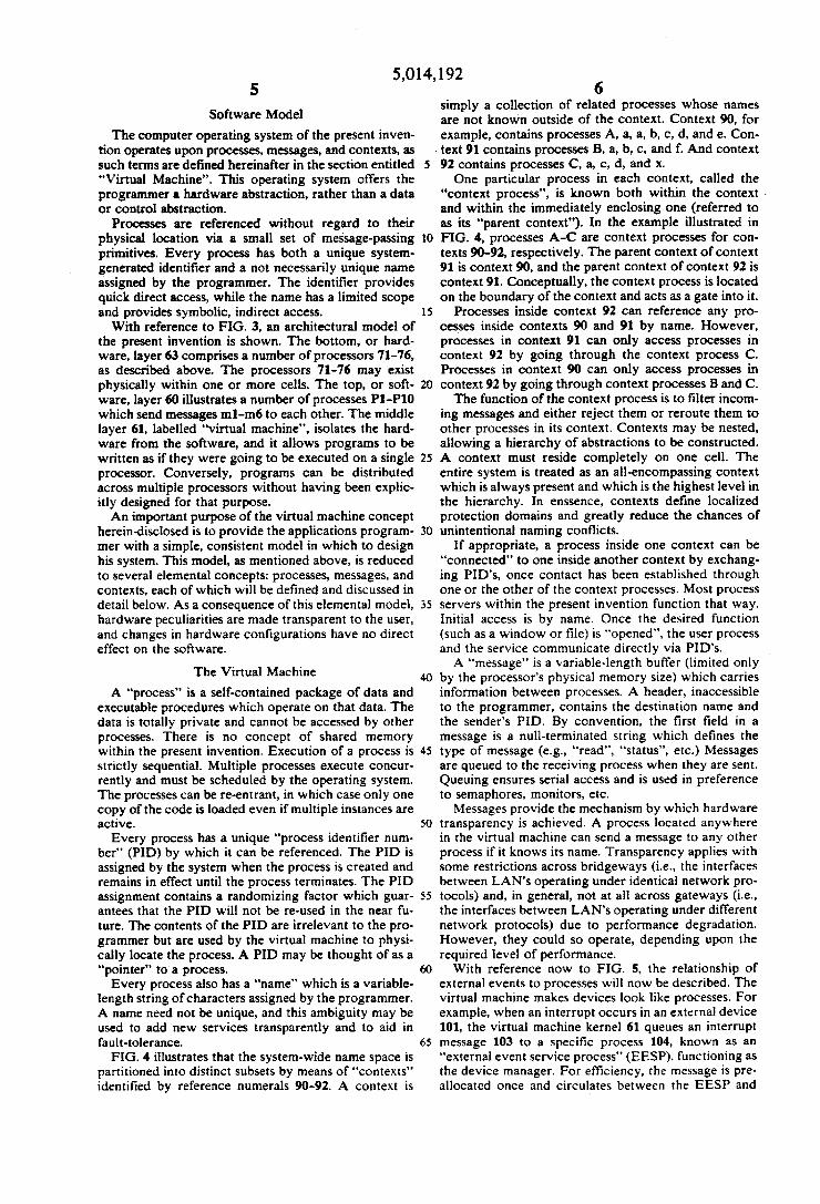
cause of insufficient space, it forwards the request on to ?le system “5" 304. If ?le system “S" 304 is capable of satisfying the request, it so noti?es user 300. Otherwise, the request continues on to each ?le system in turn until one is able to satisfy the request. If none is able to satisfy the request, an error message is returned to user 300. As mentioned above, once a ?le system fails to satisfy the request, it marks the attempt, so that it doesn't attempt to satisfy the request if the request circulates around the entire loop without being satis?ed. The flow diagram of FIG. 12 illustrates how a ?le
access request is handled by the present invention. A ?le access request is received in block 320. Decision block 321 queries whether ‘this is a wrap-around. If so, an error message is sent to the user, as indicated by block 322. If not, the procedure passes to decision block 323, which queries whether a ?le system has been speci ?ed. if not, this particular ?le system attempts to satisfy the request, as indicated by block 325. If so, decision block 324 queries whether this particular ?le system is the one speci?ed. If so, this particular ?le system at tempts to satisfy the request.
If this is not the ?le system speci?ed, then the request is marked for wrap-around, as shown by block 328, and
10
25
16 the request is forwarded to the next ?le system, as shown by block 329.
If the request can be satis?ed (block 326), then the user is so informed (block 327). If not, decision block 330 queries whether a ?le system was speci?ed. If so, an error message is sent to the user. as indicated by block 331. if not, the request is marked for wrap-around (block 328), and the request is forwarded to the next ?le system (block 329). Appendix A contains a "C" language implementation
of the flow diagram shown in FIG. 12. Appendix B is a detailed description of the relevant
portions of the source code listing of Appendix A. It will be apparent to those skilled in the art that the
herein disclosed invention may be modi?ed in numer ous ways and may assume many embodiments other than the preferred form speci?cally set out and de scribed above. For example, a ?le system may obvi ously occupy some other physical device, or portion or grouping thereof, other than a disk volume, as disclosed above. I
Accordingly, it is intended by the appended claims to cover all modi?cations of the invention which fall within the true spirit and scope of the invention.
APPENDIX A
PROGRAM LISTING‘
The following portion of the disclosure of this patent document
contains material to which a claim of copyright protection is made. The
copyright owner has no objection to the facsimile reproduction by anyone of
the patent document or the patent disclosure, as it appears in the Patent
and Trademark Office patent file or records, but reserves all other rights
whatsoever.
9 Module 1 ft le_mgt .c 1 .12 filcJngt .: l0 ' Date submi tted : 85/03/07 14 :09:29 11 Author : Bruce Hans‘! l aid 12 DESCRIPTICN - 13 --- . __.
14 I/ 15 lifndef 1 int ' . _
16 stat i 1: char Srcldl] = ‘2(8) 4 l le_mgt .c :1 .12‘; 17 lendH 13 "nun"an“usunuunuusnn/ 19 I‘ i/ 20 I! D A T A H A N A 6 E H E N T 0/ 21 /* V 22 ‘ ll 4 i lo_ngt .: 1/
24 /i§eresinn»!in»ua-ul-ieseiiatssiinuiisl 25