broadr-reach physical media attachment test suite physical media attachment test suite version 2.0...
TRANSCRIPT
BroadR-Reach Physical Media Attachment
Test Suite Version 2.0
Author & Company Curtis Donahue, UNH-IOL Title BroadR-Reach Physical Media Attachment Test Suite Version 2.0 Date January 15, 2015 Status Final Restriction Level Public
This suite of tests has been developed to help implementers evaluate the functionality of their BroadR-Reach Physical Media Attachment (PMA) based products.
y
OPEN Alliance
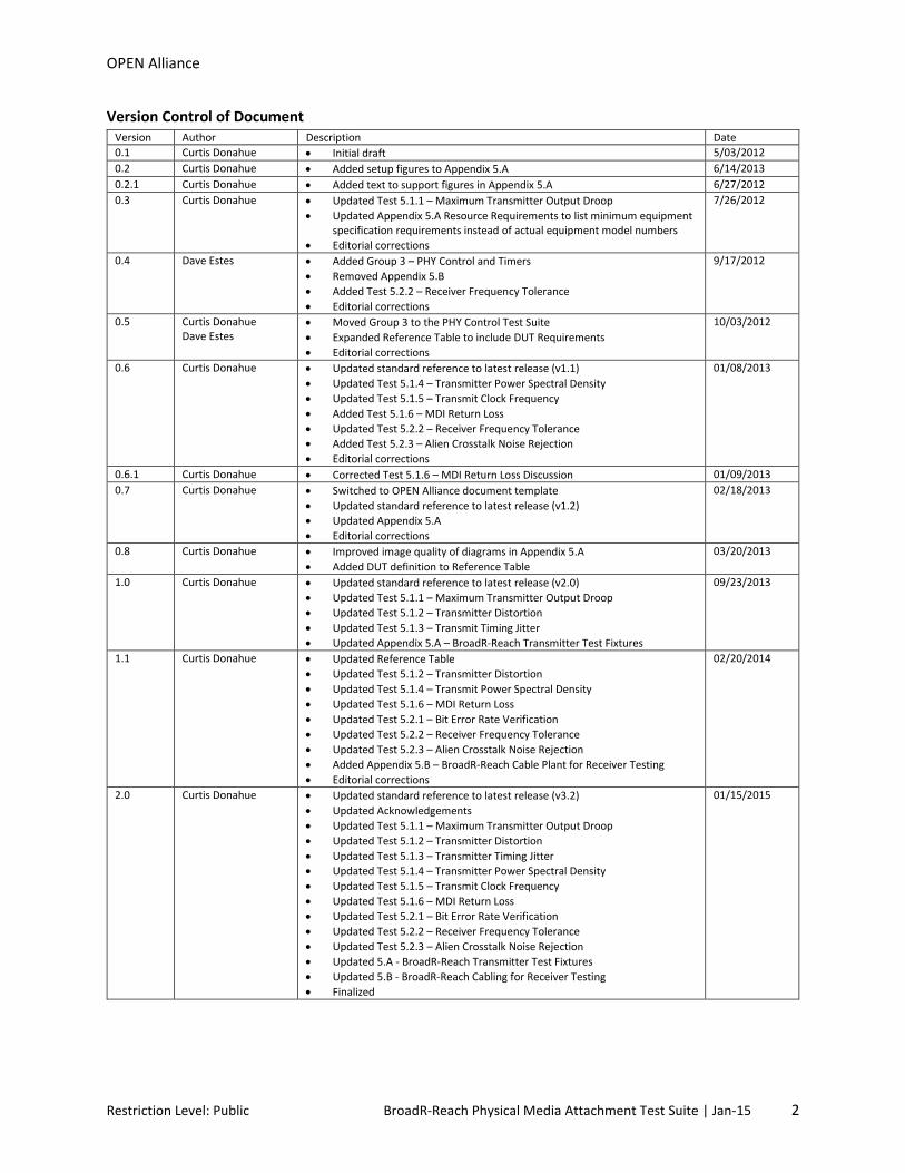
Version Control of Document Version Author Description Date 0.1 Curtis Donahue • Initial draft 5/03/2012 0.2 Curtis Donahue • Added setup figures to Appendix 5.A 6/14/2013 0.2.1 Curtis Donahue • Added text to support figures in Appendix 5.A 6/27/2012 0.3 Curtis Donahue • Updated Test 5.1.1 – Maximum Transmitter Output Droop
• Updated Appendix 5.A Resource Requirements to list minimum equipment specification requirements instead of actual equipment model numbers
• Editorial corrections
7/26/2012
0.4 Dave Estes • Added Group 3 – PHY Control and Timers • Removed Appendix 5.B • Added Test 5.2.2 – Receiver Frequency Tolerance • Editorial corrections
9/17/2012
0.5 Curtis Donahue Dave Estes
• Moved Group 3 to the PHY Control Test Suite • Expanded Reference Table to include DUT Requirements • Editorial corrections
10/03/2012
0.6 Curtis Donahue • Updated standard reference to latest release (v1.1) • Updated Test 5.1.4 – Transmitter Power Spectral Density • Updated Test 5.1.5 – Transmit Clock Frequency • Added Test 5.1.6 – MDI Return Loss • Updated Test 5.2.2 – Receiver Frequency Tolerance • Added Test 5.2.3 – Alien Crosstalk Noise Rejection • Editorial corrections
01/08/2013
0.6.1 Curtis Donahue • Corrected Test 5.1.6 – MDI Return Loss Discussion 01/09/2013 0.7 Curtis Donahue • Switched to OPEN Alliance document template
• Updated standard reference to latest release (v1.2) • Updated Appendix 5.A • Editorial corrections
02/18/2013
0.8 Curtis Donahue • Improved image quality of diagrams in Appendix 5.A • Added DUT definition to Reference Table
03/20/2013
1.0 Curtis Donahue • Updated standard reference to latest release (v2.0) • Updated Test 5.1.1 – Maximum Transmitter Output Droop • Updated Test 5.1.2 – Transmitter Distortion • Updated Test 5.1.3 – Transmit Timing Jitter • Updated Appendix 5.A – BroadR-Reach Transmitter Test Fixtures
09/23/2013
1.1 Curtis Donahue • Updated Reference Table • Updated Test 5.1.2 – Transmitter Distortion • Updated Test 5.1.4 – Transmit Power Spectral Density • Updated Test 5.1.6 – MDI Return Loss • Updated Test 5.2.1 – Bit Error Rate Verification • Updated Test 5.2.2 – Receiver Frequency Tolerance • Updated Test 5.2.3 – Alien Crosstalk Noise Rejection • Added Appendix 5.B – BroadR-Reach Cable Plant for Receiver Testing • Editorial corrections
02/20/2014
2.0 Curtis Donahue • Updated standard reference to latest release (v3.2) • Updated Acknowledgements • Updated Test 5.1.1 – Maximum Transmitter Output Droop • Updated Test 5.1.2 – Transmitter Distortion • Updated Test 5.1.3 – Transmitter Timing Jitter • Updated Test 5.1.4 – Transmitter Power Spectral Density • Updated Test 5.1.5 – Transmit Clock Frequency • Updated Test 5.1.6 – MDI Return Loss • Updated Test 5.2.1 – Bit Error Rate Verification • Updated Test 5.2.2 – Receiver Frequency Tolerance • Updated Test 5.2.3 – Alien Crosstalk Noise Rejection • Updated 5.A - BroadR-Reach Transmitter Test Fixtures • Updated 5.B - BroadR-Reach Cabling for Receiver Testing • Finalized
01/15/2015
Restriction Level: Public BroadR-Reach Physical Media Attachment Test Suite | Jan-15 2
OPEN Alliance
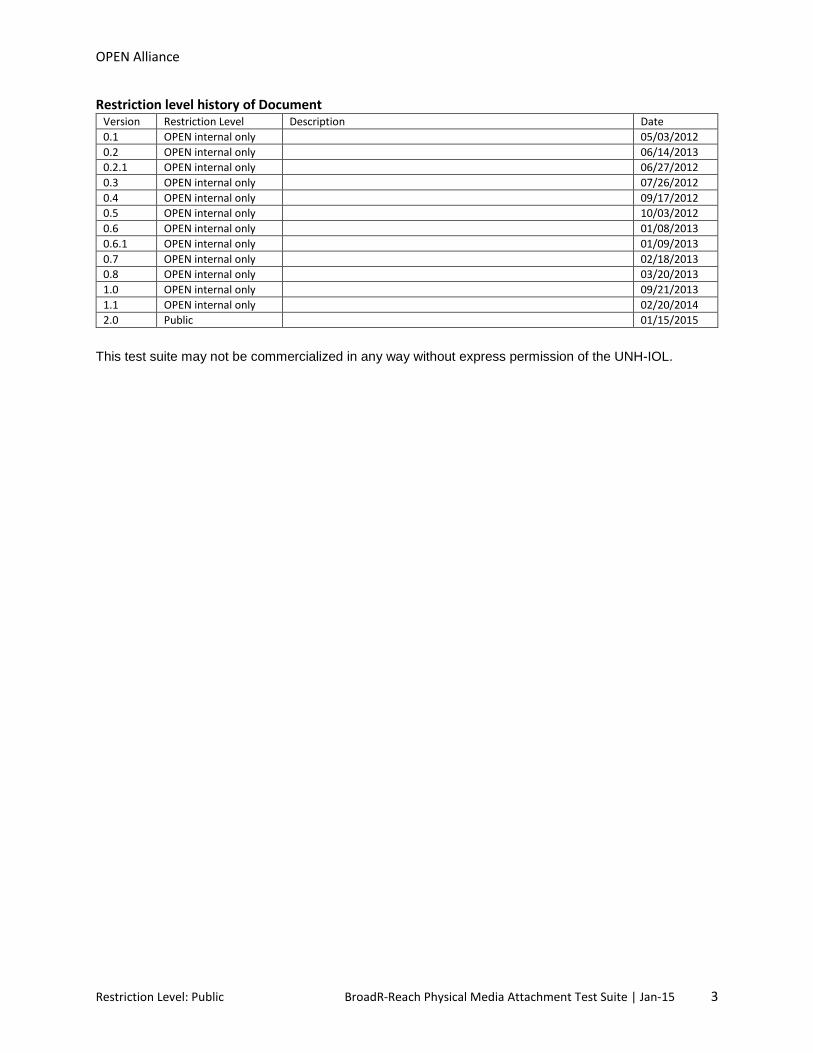
Restriction level history of Document Version Restriction Level Description Date 0.1 OPEN internal only 05/03/2012 0.2 OPEN internal only 06/14/2013 0.2.1 OPEN internal only 06/27/2012 0.3 OPEN internal only 07/26/2012 0.4 OPEN internal only 09/17/2012 0.5 OPEN internal only 10/03/2012 0.6 OPEN internal only 01/08/2013 0.6.1 OPEN internal only 01/09/2013 0.7 OPEN internal only 02/18/2013 0.8 OPEN internal only 03/20/2013 1.0 OPEN internal only 09/21/2013 1.1 OPEN internal only 02/20/2014 2.0 Public 01/15/2015
This test suite may not be commercialized in any way without express permission of the UNH-IOL.
Restriction Level: Public BroadR-Reach Physical Media Attachment Test Suite | Jan-15 3
OPEN Alliance
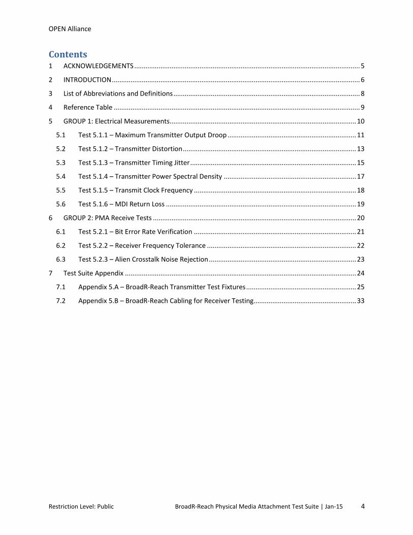
Contents 1 ACKNOWLEDGEMENTS ......................................................................................................................... 5
2 INTRODUCTION ..................................................................................................................................... 6
3 List of Abbreviations and Definitions .................................................................................................... 8
4 Reference Table .................................................................................................................................... 9
5 GROUP 1: Electrical Measurements .................................................................................................... 10
5.1 Test 5.1.1 – Maximum Transmitter Output Droop ..................................................................... 11
5.2 Test 5.1.2 – Transmitter Distortion ............................................................................................. 13
5.3 Test 5.1.3 – Transmitter Timing Jitter ......................................................................................... 15
5.4 Test 5.1.4 – Transmitter Power Spectral Density ....................................................................... 17
5.5 Test 5.1.5 – Transmit Clock Frequency ....................................................................................... 18
5.6 Test 5.1.6 – MDI Return Loss ...................................................................................................... 19
6 GROUP 2: PMA Receive Tests ............................................................................................................. 20
6.1 Test 5.2.1 – Bit Error Rate Verification ....................................................................................... 21
6.2 Test 5.2.2 – Receiver Frequency Tolerance ................................................................................ 22
6.3 Test 5.2.3 – Alien Crosstalk Noise Rejection ............................................................................... 23
7 Test Suite Appendix ............................................................................................................................ 24
7.1 Appendix 5.A – BroadR-Reach Transmitter Test Fixtures ........................................................... 25
7.2 Appendix 5.B – BroadR-Reach Cabling for Receiver Testing ....................................................... 33
Restriction Level: Public BroadR-Reach Physical Media Attachment Test Suite | Jan-15 4
OPEN Alliance
1 ACKNOWLEDGEMENTS The University of New Hampshire would like to acknowledge the efforts of the following individuals in the development of this test suite. Curtis Donahue University of New Hampshire Dave Estes University of New Hampshire Alex Seiger University of New Hampshire
Restriction Level: Public BroadR-Reach Physical Media Attachment Test Suite | Jan-15 5

OPEN Alliance
2 INTRODUCTION The University of New Hampshire’s InterOperability Laboratory (IOL) is an institution designed to improve the interoperability of standards based products by providing an environment where a product can be tested against other implementations of a standard. This particular suite of tests has been developed to help implementers evaluate the functionality of the PMA sublayer of their BroadR-Reach products. These tests are designed to determine if a product conforms to specifications defined in OPEN Alliance BroadR-Reach Physical Layer Transceiver Specification For Automotive Applications Standard. Successful completion of all tests contained in this suite does not guarantee that the tested device will operate with other devices. However, combined with satisfactory operation in the IOL’s interoperability test bed, these tests provide a reasonable level of confidence that the Device Under Test (DUT) will function properly in many BroadR-Reach automotive environments. The tests contained in this document are organized in such a manner as to simplify the identification of information related to a test, and to facilitate in the actual testing process. Tests are organized into groups, primarily in order to reduce setup time in the lab environment, however the different groups typically also tend to focus on specific aspects of device functionality. A three-part numbering system is used to organize the tests, where the first number indicates the section of the OPEN Alliance BroadR-Reach Standard on which the test suite is based. The second and third numbers indicate the test’s group number and test number within that group, respectively. This format allows for the addition of future tests to the appropriate groups without requiring the renumbering of the subsequent tests. The test definitions themselves are intended to provide a high-level description of the motivation, resources, procedures, and methodologies pertinent to each test. Specifically, each test description consists of the following sections: Purpose The purpose is a brief statement outlining what the test attempts to achieve. The test is written at the functional level. References This section specifies source material external to the test suite, including specific subsections pertinent to the test definition, or any other references that might be helpful in understanding the test methodology and/or test results. External sources are always referenced by number when mentioned in the test description. Any other references not specified by number are stated with respect to the test suite document itself. Resource Requirements The requirements section specifies the test hardware and/or software needed to perform the test. This is generally expressed in terms of minimum requirements, however in some cases specific equipment manufacturer/model information may be provided.
Restriction Level: Public BroadR-Reach Physical Media Attachment Test Suite | Jan-15 6

OPEN Alliance
Last Modification This specifies the date of the last modification to this test. Discussion The discussion covers the assumptions made in the design or implementation of the test, as well as known limitations. Other items specific to the test are covered here. Test Setup The setup section describes the initial configuration of the test environment. Small changes in the configuration should not be included here, and are generally covered in the test procedure section, below. Test Procedure The procedure section of the test description contains the systematic instructions for carrying out the test. It provides a cookbook approach to testing, and may be interspersed with observable results. Observable Results This section lists the specific observables that can be examined by the tester in order to verify that the DUT is operating properly. When multiple values for an observable are possible, this section provides a short discussion on how to interpret them. The determination of a pass or fail outcome for a particular test is generally based on the successful (or unsuccessful) detection of a specific observable. Possible Problems This section contains a description of known issues with the test procedure, which may affect test results in certain situations. It may also refer the reader to test suite appendices and/or whitepapers that may provide more detail regarding these issues.
Restriction Level: Public BroadR-Reach Physical Media Attachment Test Suite | Jan-15 7
OPEN Alliance
3 List of Abbreviations and Definitions
AFEXTDC Alien Far End Cross Conversion Loss Common to Differential ADC Analog to Digital Converter ANEXTDC Alien Near End Cross Conversion Loss Common to Differential Automotive Cable Balance 100Ω one pair cable having characteristics defined in Section 7.0 and 7.1 of the OPEN Alliance BroadR-
Reach Physical Layer Transceiver Specification For Automotive Applications Standard v3.2. BI_DA Bi-directional Data Signal Pair A BER Bit Error Rate DUT Device Under Test DSO Real-time Digital Storage Oscilloscope
DSP Digital Signal Processing ECU Electronic Control Unit LCL Longitudinal Conversion Loss LCTL Longitudinal Conversion Transmission Loss LP Link Partner MDI Medium Dependent Interface PCB Printed Circuit Board PHY Physical Layer PLL Phase Locked Loop PPM Parts Per Million PSAACRF Power Sum Attenuations to Alien Crosstalk Ratio Far End PSANEXT Power Sum Alien Near End Crosstalk Loss PSD Power Spectral Density SA RF Spectral Analyzer Short Automotive Cable Cabling representative of the ‘Automotive Cable’ definition used during transmitter testing to mate the DUT
to the necessary fixtures of each test setup. This cable should be limited in length to reduce the amount of loss between the DUT transmitter and oscilloscope frontend.
TDR Time Domain Reflectometer TIE Time Interval Error UI Unit Interval VNA RF Network Analyzer
Restriction Level: Public BroadR-Reach Physical Media Attachment Test Suite | Jan-15 8

OPEN Alliance
4 Reference Table
Test Name IOL Test
Number
Required Capabilities BroadR-Reach References
Group 1: PHY Control and Timers
Maximum Transmitter Output Droop Test 5.1.1 Test Mode 1 • Section 5.4.1 – Transmitter output droop • Section 5.2 – Test modes • Section 5.3 – Test fixtures
Transmitter Distortion Test 5.1.2 Test Mode 4 • Section 5.4.2 – Transmitter distortion • Section 5.2 – Test modes • Section 5.3 – Test fixtures
Transmitter Timing Jitter Case 1: MASTER
Test 5.1.3 Test Mode 2 • Section 5.4.3 – Transmitter timing jitter
• Section 5.2 – Test modes • Section 5.3 – Test fixtures Case 2: SLAVE TX_TCLK access
Transmitter Power Spectral Density Test 5.1.4 Test Mode 5 • Section 5.4.4 – Transmitter power spectral density • Section 5.2 – Test modes • Section 5.3 – Test fixtures
Transmit Clock Frequency Test 5.1.5 Test Mode 2 • Section 5.4.6 – Transmitter clock frequency • Section 5.2 – Test modes • Section 5.3 – Test fixtures
MDI Return Loss Test 5.1.6 Active Transmitter • Section 8.2.2 – MDI return Loss
Group 2: PHY Control State Diagram
Bit Error Rate Verification Test 5.2.1 The ability to
send and receive frames1
• Section 5.5.1 – Receiver differential input signals • Section 7 – Link segment characteristics
Receiver Frequency Tolerance Test 5.3.1 The ability to
send and receive frames1
• Section 5.5.2 – Receiver frequency tolerance
Alien Crosstalk Noise Rejection Test 5.2.3 The ability to
send and receive frames1
• Section 5.5.3 – Alien crosstalk noise rejection
1 This can be accomplished through a loopback, responding to ICMP requests, or by forwarding traffic through two ports
All tests are designed for the OPEN Alliance BroadR-Reach Physical Layer Transceiver Specification For Automotive Applications Standard v3.2 For the purposes of this test suite, the DUT is one port of a BroadR-Reach capable device that includes a BroadR-Reach PHY mounted on a PCB with an MDI connector and any necessary circuitry such as a low pass filter or common mode choke. All tests will be performed at the MDI connector of the DUT.
Restriction Level: Public BroadR-Reach Physical Media Attachment Test Suite | Jan-15 9
OPEN Alliance
5 GROUP 1: Electrical Measurements Overview:
The tests defined in this section verify the voltage parameters defined for BroadR-Reach capable PHY’s in section 5 of the OPEN Alliance BroadR-Reach Standard v3.2.
Restriction Level: Public BroadR-Reach Physical Media Attachment Test Suite | Jan-15 10

OPEN Alliance
5.1 Test 5.1.1 – Maximum Transmitter Output Droop Purpose: To verify that the transmitter output level does not droop more than the maximum specified amount. References:
[1] OPEN Alliance BroadR-Reach Physical Layer Transceiver Specification For Automotive Applications Standard v3.2, section 5.2 - Test modes
[2] Ibid., section 5.3 - Test Fixtures [3] Ibid., section 5.4.1 - Transmitter Output Droop [4] Test suite appendix 5.A – BroadR-Reach Transmitter Test Fixtures
Resource Requirements:
• DSO • 2-pin to SMA Adapter • Short Automotive Cable • 50Ω coaxial cables, matched length
Last Modification: January 15, 2015 (version 2.0) Discussion:
Reference [1] states that a BroadR-Reach device shall implement 5 test modes. These test modes are provided to measure electrical characteristics and verify compliance. Reference [2] defines the test fixture to be used to perform the test. Reference [1] defines the operation of a device while in test mode 1, and reference [3] provides a specification for the maximum allowable droop for the transmitter.
This test requires the DUT to operate in transmitter test mode 1. While in test mode 1, the DUT shall generate a sequence of at least 40 +1 symbols followed by at least 40 -1 symbols continually transmitted.
Droop is calculated after measuring the peak voltage (Vpk) and the voltage 500 ns after the peak (Vdelay). The difference Vd = Vpk - Vdelay. Droop = Vd/Vpk * 100%. This is performed on both the positive and negative peaks of the waveform transmitted by test mode 1. The magnitude of the droop should be less than 45.0%.
Test Setup: Refer to test suite appendix 5.A.3 Procedure:
1. Configure the DUT so that it is operating in transmitter test mode 1. 2. Connect BI_DA from the MDI to Test Fixture 1. 3. Find the rising-edge initial peak voltage (Vpk) in the waveform. 4. Measure the amplitude of the waveform at 500 ns after the initial peak (Vdelay) to find the droop
voltage (Vd). 5. Compute the droop between Vpk and Vd. 6. For enhanced accuracy, repeat steps 3-5 multiple times and average the results. 7. Repeat using a falling edge reference.
Restriction Level: Public BroadR-Reach Physical Media Attachment Test Suite | Jan-15 11

OPEN Alliance
Observable Results:
a. The magnitude of both the positive and negative droop shall be less than 45.0%.
Possible Problems: None.
Restriction Level: Public BroadR-Reach Physical Media Attachment Test Suite | Jan-15 12
OPEN Alliance
5.2 Test 5.1.2 – Transmitter Distortion Purpose: To verify that the distortion of the transmitter is within the conformance limits. References:
[1] OPEN Alliance BroadR-Reach Physical Layer Transceiver Specification For Automotive Applications Standard v3.2, section 5.2 - Test modes
[2] Ibid., section 5.3 - Test Fixtures [3] Ibid., section 5.4.2 - Transmitter Distortion [4] Test suite appendix 5.A – BroadR-Reach Transmitter Test Fixtures
Resource Requirements: • DSO • High Impedance Differential Probe • Short Automotive Cable • Transmitter Distortion Adapter
Last Modification: January 15, 2015 (version 2.0) Discussion:
Reference [1] states that a BroadR-Reach device shall implement 5 test modes. These test modes are provided to measure electrical characteristics and verify compliance. Reference [2] defines the test fixture to be used to perform the test, as well as the disturbing signal characteristics (see [4] for more details). Reference [1] defines the operation of a device while in test mode 4, and reference [3] provides a specification for the maximum allowable distortion for the transmitter.
In this test, the peak distortion is measured by capturing the test mode 4 waveform and finding the least mean squared error. The peak error between the ideal reference and the observed symbols is the peak transmitter distortion. Reference [3] provides Matlab code for determining the peak distortion, note this code assumes the disturber signal and the data acquisition clock of the oscilloscope are frequency locked to the DUT TX_TCLK.
Test Setup: Refer to appendix 5.A.4 Procedure:
1. Configure the DUT so that it is sourcing the transmitter test mode 4 waveform. 2. Configure the disturber source as described in [2]. 3. Connect BI_DA from the MDI to Test Fixture 2. 4. Capture 2ms of consecutive symbols in the test mode 4 waveform. 5. Using the code provided in [3], process the 2ms capture in Matlab to calculate the peak
distortion at 10 uniformly spaced phase offsets over 1 UI. Observable Results:
a. The peak transmitter distortion should be less than 15mV for all of the sampled phase offsets over 1 UI.
Restriction Level: Public BroadR-Reach Physical Media Attachment Test Suite | Jan-15 13

OPEN Alliance
Possible Problems: a. If the vertical resolution of the oscilloscope is less than 10 bits, then a low pass filter must be
used during post-processing. The Matlab code provided in [3] includes such a LPF. b. If the TX_TCLK of the DUT is not accessible or the DUT does not have an external clock input, the
test equipment will not be able to synchronize internal sampling clocks. Because of this, phase offsets will occur in test equipment and measured distortion values will most likely be worse than if the DUT’s TX_TCLK was available.
Restriction Level: Public BroadR-Reach Physical Media Attachment Test Suite | Jan-15 14
OPEN Alliance
5.3 Test 5.1.3 – Transmitter Timing Jitter Purpose: To verify that the transmitter timing jitter of the PMA is within the conformance limits. References:
[1] OPEN Alliance BroadR-Reach Physical Layer Transceiver Specification For Automotive Applications Standard v3.2, section 5.2 - Test modes
[2] Ibid., section 5.3 - Test Fixtures [3] Ibid., section 5.4.3 - Transmit timing jitter [4] Test suite appendix 5.A – BroadR-Reach Transmitter Test Fixtures
Resource Requirements: • DSO • 2-pin to SMA Adapter • Short Automotive Cable • 50Ω Coaxial Cables, matched length
Last Modification: January 15, 2015 (version 2.0) Discussion:
Reference [1] states that a BroadR-Reach device shall implement 5 test modes. These test modes are provided to measure electrical characteristics and verify compliance. Reference [2] defines the test fixture to be used to perform the test. Reference [3] provides a specification for the maximum allowable timing jitter for the transmitter.
Case 1 – MASTER transmitter timing jitter
When in test mode 2, the PHY transmits +1 symbols followed by -1 symbols continuously. In this
mode, the transmitter output should be a 3313 MHz signal and the RMS TIE jitter measured at the
PHY MDI output shall be less than 50 ps. The RMS period jitter is measured over an integration time interval of at least 1 ms.
Case 2 – SLAVE transmitter timing jitter (if applicable) SLAVE transmitter timing jitter can only be performed when the DUTs TX_TCLK is exposed and accessible. For normal operation as the SLAVE, the DUTs reference clock is recovered from a compliant LP PHY operating as MASTER. The RMS TIE jitter of the SLAVE TX_TCLK shall not exceed 0.01 UI (150 ps).
Test Setup: Refer to test suite appendix 5.A.3 Procedure: Case 1 – MASTER transmitter timing jitter
1. Configure the DUT so that it is operating in transmitter test mode 2.
Restriction Level: Public BroadR-Reach Physical Media Attachment Test Suite | Jan-15 15
OPEN Alliance
2. Connect BI_DA from the MDI to Test Fixture 1. 3. Capture at least 1ms and process the capture to determine the RMS TIE jitter. 4. For enhanced accuracy, repeat step 3 multiple times.
Case 2 – SLAVE transmitter timing jitter
1. Configure the DUT so that it is operating in normal mode, forced to SLAVE. 2. Configure the LP so that it is operating in normal mode, forced to MASTER. 3. Connect the DUT TX_TCLK to channel 2 of the DSO. 4. Capture at least 1ms and process the capture with a PC to determine the RMS TIE jitter. 5. For enhanced accuracy, repeat step 4 multiple times.
Observable Results: Case 1 – MASTER transmitter timing jitter
a. The RMS TIE jitter measured at the MDI output should not exceed 50 ps.
Case 2 – SLAVE transmitter timing jitter (if applicable) a. The RMS TIE jitter of the SLAVE TX_TCLK should not exceed 0.01 UI (150 ps).
Possible Problems: If the DUT does not provide access to the TX_TCLK, SLAVE jitter (case 2) testing cannot be performed.
Restriction Level: Public BroadR-Reach Physical Media Attachment Test Suite | Jan-15 16

OPEN Alliance
5.4 Test 5.1.4 – Transmitter Power Spectral Density Purpose: To verify the transmitter power spectral density are within the conformance limits. References:
[1] OPEN Alliance BroadR-Reach Physical Layer Transceiver Specification For Automotive Applications Standard v3.2, section 5.2 - Test modes
[2] Ibid., section 5.3 - Test Fixtures [3] Ibid., section 5.4.4 - Transmitter Power Spectral Density (PSD) [4] Test suite appendix 5.5.A – BroadR-Reach Transmitter Test Fixtures
Resource Requirements:
• SA or DSO with spectral measurement capabilities • Balun • 2-pin to SMA Adapter • Short Automotive Cable • 50Ω coaxial cables, matched length
Last Modification: January 15, 2015 (version 2.0) Discussion: Reference [1] states that a BroadR-Reach device shall implement 5 test modes. These test modes are provided to measure electrical characteristics and verify compliance. Reference [2] defines the test fixture to be used to perform the test. Reference [1] defines the operation of a device while in test mode 5, and reference [3] provides the transmitter PSD mask. Test Setup: Refer to test suite appendix 5.A.5 Procedure:
1. Configure the DUT so that it is operating in transmitter test mode 5. 2. Connect BI_DA from the MDI to Test Fixture 3. 3. Capture the spectrum of the transmitted test mode waveform using a SA (or DSO). 4. For enhanced accuracy, repeat step 3 multiple times and average the power measured at each
point. 5. Compute the transmitter PSD.
Observable Results:
a. The PSD of the transmitter output while operating in test mode 5 shall fit within the transmitter PSD mask defined in [3].
Possible Problems: None.
Restriction Level: Public BroadR-Reach Physical Media Attachment Test Suite | Jan-15 17

OPEN Alliance
5.5 Test 5.1.5 – Transmit Clock Frequency Purpose: To verify that the frequency of the Transmit Clock is within the conformance limits References:
[1] OPEN Alliance BroadR-Reach Physical Layer Transceiver Specification For Automotive Applications Standard v3.2, section 5.4.5 - Transmit Clock Frequency
[2] Test suite appendix 5.A – BroadR-Reach Transmitter Test Fixtures Resource Requirements:
• DSO • 2-pin to SMA Adapter • Short Automotive Cable • 50Ω coaxial cables, matched length
Last Modification: January 15, 2015 (version 2.0) Discussion:
Reference [1] states that all BroadR-Reach devices must have a symbol transmission rate of 6623
MHz ± 100ppm while operating in MASTER timing mode. This corresponds to a transmit clock of 66.6603 MHz to 66.6736 MHz.
The reference clock used in this test is the one obtained in test 5.1.3, Transmitter Timing Jitter - Case 1. The frequency of this clock, extracted from the transmitted test mode 2 waveform, shall have a
base frequency of 6623 MHz ± 100ppm.
Test Setup: Refer to test suite appendix 5.A.3 Procedure:
1. Configure the DUT for test mode 2 operation. 2. Connect BI_DA from the MDI to Test Fixture 1. 3. Using a narrow-bandwidth PLL, extract the clock frequency from the transmitted symbols. 4. For enhanced accuracy, repeat step 2 multiple times. 5. Measure the frequency of the transmit clock.
Observable Results:
a. The transmit clock generated by the DUT shall have a frequency between 66.6603MHz and 66.6736MHz.
Possible Problems: None.
Restriction Level: Public BroadR-Reach Physical Media Attachment Test Suite | Jan-15 18

OPEN Alliance
5.6 Test 5.1.6 – MDI Return Loss Purpose: To measure the return loss at the MDI. References:
[1] OPEN Alliance BroadR-Reach Physical Layer Transceiver Specification For Automotive Applications Standard v3.2, section 8.2.2 – MDI Return Loss
[2] Test suite appendix 5.A – BroadR-Reach Transmitter Test Fixtures Resource Requirements:
• VNA or TDR with frequency domain capabilities • Balun • 2-pin to SMA Adapter • Short Automotive Cable • 50Ω coaxial Cables, matched length
Last Modification: January 15, 2015 (version 2.0) Discussion:
A compliant BroadR-Reach device shall ideally have a differential characteristic impedance of 100Ω. This is necessary to match the characteristic impedance of the automotive cabling. Any difference between these impedances will result in a partial reflection of the transmitted signals. Return loss is a measure of the signal power that is reflected due to the impedance mismatch. Reference [1] specifies the conformance limits for the reflected power measured at the MDI. The specification states that the return loss must be maintained transmitting data or control symbols. Test Setup: Refer to test suite appendix 5.A.6 Procedure:
1. Configure the DUT for test mode 4 operation. 2. Calibrate the VNA (or TDR) to remove the effects of the test jig and connecting cable. 3. Connect the BI_DA from the MDI to the reflection port of the network analyzer. 4. Measure the reflections at the MDI referenced to a 100Ω characteristic impedance.
Observable Results:
a. The return loss measured at the MDI shall be at least 20 dB from 1 to 30MHz, and at least 20-20*log10(f/30) dB from 30 to 66MHz when referenced to a characteristic impedance of 100Ω.
Possible Problems: None.
Restriction Level: Public BroadR-Reach Physical Media Attachment Test Suite | Jan-15 19

OPEN Alliance
6 GROUP 2: PMA Receive Tests Overview:
This section verifies the integrity of the BroadR-Reach PMA Receiver through frame reception tests.
Restriction Level: Public BroadR-Reach Physical Media Attachment Test Suite | Jan-15 20

OPEN Alliance
6.1 Test 5.2.1 – Bit Error Rate Verification Purpose: To verify that the DUT can maintain a BER of less than 10-10. References:
[1] OPEN Alliance BroadR-Reach Physical Layer Transceiver Specification For Automotive Applications Standard v3.2, section 5.5.1 - Receiver Differential Input Signals
[2] Ibid., section 7 – Link Segment Characteristics [3] IOL TP-PMD Test Suite Appendix 25.D [4] Appendix 5.B - BroadR-Reach Cabling for Receiver Testing
Resource Requirements:
• Packet transmit/monitoring station • Automotive cables of varying lengths
Last Modification: January 15, 2015 (version 2.0) Discussion: Reference [1] states that a BroadR-Reach capable PHY shall not exceed a BER of less than 10-10. The cables used for receiver BER testing are automotive cables, conformant to the characteristics described in [2] but representative of a worst case channel. Channel characteristics of the worst case channel are further discussed in [4]. Packet transmit and monitoring stations are used to verify the BER of the DUT.
Based on the analysis given in reference [3], if more than 7 errors are observed in 3x10¹⁰
bits
(about 2,470,000 1,518-byte packets), it can be concluded that the error rate is greater than 10-10
with less than a 5% chance of error. Note that if no errors are observed, it can be concluded that the BER is no
more than 10-10
with less than a 5% chance of error.
Test Setup: Refer to test suite appendix 5.A.7 Procedure:
1. Configure the DUT as MASTER. 2. Connect the packet monitoring station to the automotive cable. 3. Connect the DUT to the automotive cable. 4. Send 2,470,000 1,518-byte packets (for a 10-10 BER) and the monitor will count the number of
packet errors. 5. Repeat step 4 for the remaining automotive cables. 6. Repeat steps 4-5 with the DUT configured as SLAVE.
Observable Results:
a. The DUT shall maintain a BER of less than 10-10 for all automotive cable lengths. Possible Problems: None.
Restriction Level: Public BroadR-Reach Physical Media Attachment Test Suite | Jan-15 21
OPEN Alliance
6.2 Test 5.2.2 – Receiver Frequency Tolerance
Purpose: To verify that the DUT can properly accept incoming data with the symbol rate of 66 23 MHz +/-
100 ppm. References:
[1] OPEN Alliance BroadR-Reach Physical Layer Transceiver Specification For Automotive Applications Standard v3.2, section 5.5.2 - Receiver Frequency Tolerance
[2] Ibid., section 7 – Link Segment Characteristics [3] Appendix 5.B - BroadR-Reach Cabling for Receiver Testing
Resource Requirements:
• Packet transmit/monitoring station capable of a configurable transmit clock • Automotive cable representative of worst case channel
Last Modification: January 15, 2015 (version 2.0) Discussion: Reference [1] states that a BroadR-Reach capable PHY shall properly accept incoming data with
the symbol rate of 66 23 MHz +/- 100 ppm. This corresponds to a transmit clock of 66.6603MHz to 66.6736
MHz. Please refer to Test 5.2.1 – Bit Error Rate Verification, of this document, for further details regarding the worst case channel and packet analysis. The cables used for receiver frequency tolerance testing are automotive cables, conformant to the characteristics described in [2] but representative of a worst case channel. Channel characteristics of the worst case channel are further described in [3]. Test Setup: Refer to test suite appendix 5.A.7 Procedure: Part A
1. Configure the DUT as SLAVE. 2. Connect the packet transmit/monitoring station to the automotive cable. 3. Connect the DUT to the automotive cable. 4. Configure the packet transmit/monitoring station to transmit data with a clock of 66.6603 MHz. 5. Send 2,470,000 1,518-byte packets (for a 10-10 BER) and monitor the number of packet errors. 6. Repeat step 3-5 using a transmit clock of 66.6736 MHz.
Observable Results:
a. The DUT shall maintain a BER of less than 10-10 when recovering a transmit clock of 66.6603 MHz or 66.6736 MHz for all automotive cable lengths.
Possible Problems: None.
Restriction Level: Public BroadR-Reach Physical Media Attachment Test Suite | Jan-15 22
OPEN Alliance
6.3 Test 5.2.3 – Alien Crosstalk Noise Rejection Purpose: To verify that the DUT can maintain a bit error rate of less than 10-10 in the presence of a
crosstalk noise source. References:
[1] OPEN Alliance BroadR-Reach Physical Layer Transceiver Specification For Automotive Applications Standard v3.2, section 5.5.3 – Alien Crosstalk Noise Rejection
[2] Ibid., section 7 – Link Segment Characteristics [3] Appendix 5.B - BroadR-Reach Cabling for Receiver Testing
Resource Requirements: • Packet transmit/monitoring station • Worst case automotive crosstalk noise injection cable • BroadR-Reach 100 Mbps idle symbol noise source
Last Modification: January 15, 2015 (version 2.0) Discussion: Reference [1] defines a test cable which uses a resistive network to inject crosstalk noise into the receive path of the DUT. Reference [1] goes on to state that a BroadR-Reach capable PHY shall not exceed a BER of less than 10-10, even with alien crosstalk noise present. The cables used for receiver frequency tolerance testing are automotive cables, conformant to the characteristics described in [2] but representative of a worst case channel. Channel characteristics of the worst case channel are further discussed in [3]. Test Setup: Refer to test suite appendix 5.A.8 Procedure:
1. Configure the DUT as MASTER. 2. Connect the packet transmit/monitoring station to the worst case automotive crosstalk noise
injection cable. 3. Connect the DUT to the worst case automotive crosstalk noise injection cable. 4. Send 2,470,000 1,518-byte packets (for a 10-10 BER) and the monitor will count the number of
packet errors. 5. Repeat step 4 with the DUT configured as SLAVE.
Observable Results:
a. The DUT shall maintain a BER of less than 10-10 when using the worst case automotive crosstalk noise injection cable.
Possible Problems: None.
Restriction Level: Public BroadR-Reach Physical Media Attachment Test Suite | Jan-15 23

OPEN Alliance
7 Test Suite Appendix Overview:
The appendices contained in this section are intended to provide additional low-level technical details pertinent to specific tests defined in this test suite. Test suite appendices often cover topics that are beyond the scope of the standard, but are specific to the methodologies used for performing the measurements covered in this test suite. This may also include details regarding a specific interpretation of the standard (for the purposes of this test suite), in cases where a specification may appear unclear or otherwise open to multiple interpretations. Scope: Test suite appendices are considered informative, and pertain only to tests contained in this test suite.
Restriction Level: Public BroadR-Reach Physical Media Attachment Test Suite | Jan-15 24

OPEN Alliance
7.1 Appendix 5.A – BroadR-Reach Transmitter Test Fixtures Purpose: To provide a reference implementation of Test Fixtures 1 through 3 as well as other transmit
and receive test setups. References:
[1] OPEN Alliance BroadR-Reach Physical Layer Transceiver Specification For Automotive Applications Standard v3.2, section 5.3 - Test fixtures
[2] Ibid., section 7.0 – Link Segment characteristics [3] Ibid., section 8.0 – MDI specification [4] Ibid., section 5.5.3 – Alien Crosstalk Noise Rejection
[5] IOL TP-PMA Test Suite Appendix 40.B [6] Appendix 5.B - BroadR-Reach Cabling for Receiver Testing
Resource Requirements: • DSO: Capable of 1 GHz DSO bandwidth and a sampling rate of 2 GS/s or higher. • SA: Capable of operating up to 200 MHz with a dynamic range of 50 dBm or higher, or
equivalent Digital oscilloscope with spectral measurement capabilities. • VNA: Capable of measuring up to 100 MHz, or equivalent TDR with frequency domain
capabilities • Packet transmit/monitoring system • 2-pin to SMA Adapter • Transmitter distortion Adapter • High Impedance Differential Probe: Capable of operating up to 1 GHz or higher. • Balun: Capable of operating up to 200 MHz or higher. • Disturbing signal generator: Capable of producing a sinusoid with differential amplitude of 5.4
Vpp and a frequency of 11.111 MHz • Automotive cabling: Various lengths • 50Ω coaxial cables, matched length • Worst case automotive crosstalk noise injection cable • BroadR-Reach 100Mbps Idle Symbol Noise Source
Last Modification: January 15, 2015 (version 2.0) Discussion: 5.A.1- Introduction Reference [1] defines three test fixtures to be used in the verification of BroadR-Reach transmitter specifications. The purpose of this appendix is to present a reference implementation of these test fixtures. This appendix describes test setups that can be used as Test Fixtures 1 through 3, a setup for Return Loss, and Group 2: PMA Receive Test measurements. 5.A.2 – Cabling and Adapters
Restriction Level: Public BroadR-Reach Physical Media Attachment Test Suite | Jan-15 25
OPEN Alliance
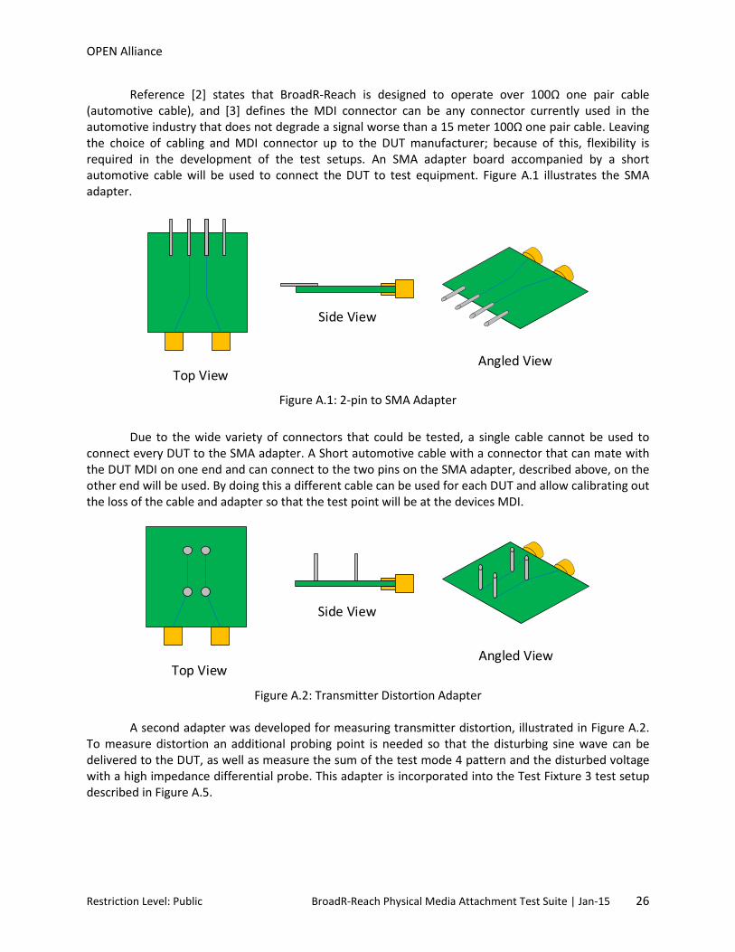
Reference [2] states that BroadR-Reach is designed to operate over 100Ω one pair cable (automotive cable), and [3] defines the MDI connector can be any connector currently used in the automotive industry that does not degrade a signal worse than a 15 meter 100Ω one pair cable. Leaving the choice of cabling and MDI connector up to the DUT manufacturer; because of this, flexibility is required in the development of the test setups. An SMA adapter board accompanied by a short automotive cable will be used to connect the DUT to test equipment. Figure A.1 illustrates the SMA adapter.
Figure A.1: 2-pin to SMA Adapter
Due to the wide variety of connectors that could be tested, a single cable cannot be used to
connect every DUT to the SMA adapter. A Short automotive cable with a connector that can mate with the DUT MDI on one end and can connect to the two pins on the SMA adapter, described above, on the other end will be used. By doing this a different cable can be used for each DUT and allow calibrating out the loss of the cable and adapter so that the test point will be at the devices MDI.
Figure A.2: Transmitter Distortion Adapter
A second adapter was developed for measuring transmitter distortion, illustrated in Figure A.2. To measure distortion an additional probing point is needed so that the disturbing sine wave can be delivered to the DUT, as well as measure the sum of the test mode 4 pattern and the disturbed voltage with a high impedance differential probe. This adapter is incorporated into the Test Fixture 3 test setup described in Figure A.5.
Top View
Side View
Angled View
Top View
Side View
Angled View
Restriction Level: Public BroadR-Reach Physical Media Attachment Test Suite | Jan-15 26
OPEN Alliance
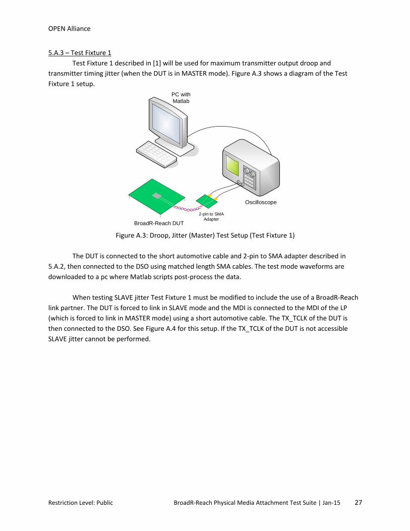
5.A.3 – Test Fixture 1 Test Fixture 1 described in [1] will be used for maximum transmitter output droop and transmitter timing jitter (when the DUT is in MASTER mode). Figure A.3 shows a diagram of the Test Fixture 1 setup.
Figure A.3: Droop, Jitter (Master) Test Setup (Test Fixture 1)
The DUT is connected to the short automotive cable and 2-pin to SMA adapter described in
5.A.2, then connected to the DSO using matched length SMA cables. The test mode waveforms are downloaded to a pc where Matlab scripts post-process the data.
When testing SLAVE jitter Test Fixture 1 must be modified to include the use of a BroadR-Reach
link partner. The DUT is forced to link in SLAVE mode and the MDI is connected to the MDI of the LP (which is forced to link in MASTER mode) using a short automotive cable. The TX_TCLK of the DUT is then connected to the DSO. See Figure A.4 for this setup. If the TX_TCLK of the DUT is not accessible SLAVE jitter cannot be performed.
Oscilloscope
PC with Matlab
BroadR-Reach DUT
2-pin to SMAAdapter
Restriction Level: Public BroadR-Reach Physical Media Attachment Test Suite | Jan-15 27

OPEN Alliance
Figure A.4: Jitter (SLAVE) Test Setup
5.A.4 – Test Fixture 2 In Test Fixture 2, the DUT is directly connected to a 100Ω differential voltage generator. The voltage generator transmits a sine wave of specific frequency and amplitude; which is referred to as the disturbing signal, Vd. An oscilloscope monitors the output of the DUT through a high impedance differential probe. The disturbing sine wave characteristics are given in Table A-1.
Table A-1: Characteristics of disturber waveform Vd Amplitude Vd Frequency
5.4 V peak-to-peak 11.111 MHz
The purpose of Vd is to simulate the presence of a remote transmitter. If the DUT is not sufficiently
linear, the disturbing signal will cause significant distortion products to appear in the DUT output. Note that while the oscilloscope sees the sum of the Vd and the DUT output, only the DUT output is of interest. Therefore post-processing is required to remove the disturbing signal from the measurement.
Upon looking at the Test Fixture 3 definition shown in [1], it is important to note that Vd is
defined as the voltage before the 50Ω resistors. Thus, the amount of voltage seen at the transmitter under test is 50% of the original amplitude of Vd.
Oscilloscope
PC with Matlab
BroadR-Reach DUT
TX_TCLK
BroadR-Reach LP
Restriction Level: Public BroadR-Reach Physical Media Attachment Test Suite | Jan-15 28

OPEN Alliance
Figure A.5: Distortion Test Setup (Test Fixture 2)
The BroadR-Reach specification requires the test equipment used for transmit distortion
measurements be synchronized with the DUT’s TX_TCLK, this guarantees that the internal sampling clock of each piece of equipment shares a common clock source and is phase locked. How to generate a reference clock from the TX_TCLK is not defined but can be achieved in several ways. Using a frequency
divider to generate a 10 MHz clock from the 6623 MHz TX_CLK is one such technique. This is depicted in
Figure A.4 with a dashed line. However, depending on the DUT’s design and form factor the TX_TCLK may not be exposed or brought out to a probe-able pin. When the TX_TCLK is not accessible distortion testing will need to be tested without test equipment synchronization. Because of this phase offsets will occur between the clock sources of each test equipment, and measured distortion values will most likely be worse than if the DUT’s TX_TCLK was available.
A Matlab script is provided in the BroadR-Reach specification to calculate transmitter distortion.
Embedded within the script are hardware requirements for the oscilloscope used to capture the test mode 4 pattern. The requirements include a sample rate of 2GS/s and an ADC vertical resolution of 8 bits or more. It also goes on to state that if the ADC resolution is less than 10 bits then the data is to be
processed through an optional section of code that includes a 3313 MHz low pass filter. However since
the oscilloscope sample rate and ADC resolution are not discussed outside the Matlab code it makes the implementation of the optional code subjective and left to the interpretation of the tester. Additionally, ADC vertical resolution settings available to the user will differ from equipment vendor to equipment vendor. There are DSOs in the market that offer >8 bit native ADC vertical resolution but most DSOs have a native ADC vertical resolution of 8 bits. Depending on the DSO the ADC resolution may be increased above the native settings, this is achieved by applying DSP techniques. The exact details of the
Oscilloscope
PC with Matlab
BroadR-Reach DUT
Transmitter Distortion Adapter
DisturberGenerator
RefInput
RefInput
Input
Output
FrequencyDivider
TX_TCLK
High ImpedanceDifferential
Probe
Restriction Level: Public BroadR-Reach Physical Media Attachment Test Suite | Jan-15 29

OPEN Alliance
DSP used to increase the ADC resolution is proprietary and is up to the equipment vendor to divulge. Since the DSP techniques used to increase the ADC resolution are not fully available to the user it is possible that the unspecified filtering can artificially lower distortion values. Measured distortion values will vary significantly based on the ADC settings, care should be taken when choosing ADC settings. For testing performed at the IOL, equipment will be chosen so that when testing transmitter distortion the sample rate will be exactly 2GS/s and the Matlab low pass filter will only be used if the native ADC resolution is less than 10 bits. 5.A.5 – Test Fixture 3 Test Fixture 3 described in [1] will be used for transmitter PSD measurements. The PSD profile is downloaded from the SA and post-processed in Matlab. Figure A.6 shows a diagram of the Test Fixture 3 setup. A balun is necessary to convert the differential transmission of the DUT to a single-ended input for the SA.
Figure A.6: PSD Test Setup (Test Fixture 3)
5.A.6 – MDI Return Loss Setup The MDI return loss measurement is performed with a VNA. Depending on the design of the VNA there may only be a single input port, if this is the case a balun will need to be used to convert the differential transmission of the DUT to a single-ended input for the VNA. See figure A.7. However, if the VNA has two or more input ports a balun is not necessary, see Figure A.8.
Spectrum Analyzer
PC with Matlab
BroadR-Reach DUT
2-pin to SMAAdapter
Balun
Restriction Level: Public BroadR-Reach Physical Media Attachment Test Suite | Jan-15 30
OPEN Alliance
Figure A.7: MDI Return Loss with Single Input VNA
Figure A.8: MDI Return Loss with Two Input VNA
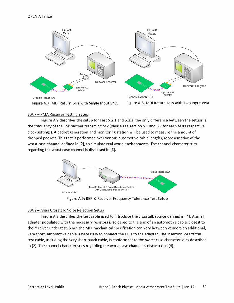
5.A.7 – PMA Receiver Testing Setup Figure A.9 describes the setup for Test 5.2.1 and 5.2.2, the only difference between the setups is the frequency of the link partner transmit clock (please see section 5.1 and 5.2 for each tests respective clock settings). A packet generation and monitoring station will be used to measure the amount of dropped packets. This test is performed over various automotive cable lengths, representative of the worst case channel defined in [2], to simulate real world environments. The channel characteristics regarding the worst case channel is discussed in [6].
Figure A.9: BER & Receiver Frequency Tolerance Test Setup
5.A.8 – Alien Crosstalk Noise Rejection Setup Figure A.9 describes the test cable used to introduce the crosstalk source defined in [4]. A small adapter populated with the necessary resistors is soldered to the end of an automotive cable, closest to the receiver under test. Since the MDI mechanical specification can vary between vendors an additional, very short, automotive cable is necessary to connect the DUT to the adapter. The insertion loss of the test cable, including the very short patch cable, is conformant to the worst case characteristics described in [2]. The channel characteristics regarding the worst case channel is discussed in [6].
Network Analyzer
PC with Matlab
BroadR-Reach DUT
2-pin to SMAAdapter
Balun
Network Analyzer
PC with Matlab
BroadR-Reach DUT
2-pin to SMAAdapter
PC with Matlab
BroadR-Reach DUT
BroadR-Reach LP Packet Monitoring Systemwith Configurable Transmit Clock
Restriction Level: Public BroadR-Reach Physical Media Attachment Test Suite | Jan-15 31
OPEN Alliance
*Link segments not drawn to scale
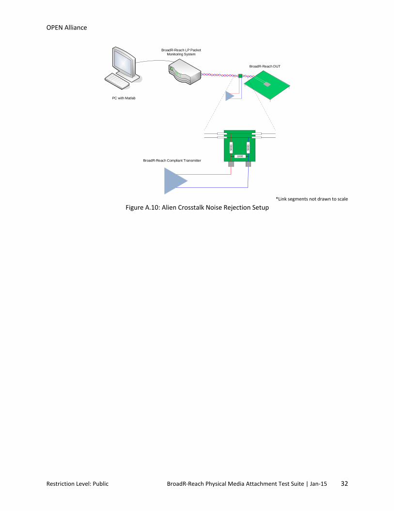
Figure A.10: Alien Crosstalk Noise Rejection Setup
PC with Matlab
BroadR-Reach DUT
BroadR-Reach LP Packet Monitoring System
100Ω
500Ω
500Ω
BroadR-Reach Compliant Transmitter
Restriction Level: Public BroadR-Reach Physical Media Attachment Test Suite | Jan-15 32

OPEN Alliance
7.2 Appendix 5.B – BroadR-Reach Cabling for Receiver Testing Purpose: To describe the characteristics of various automotive cables used to verify BER, Receiver
Frequency Tolerance, and Alien Crosstalk Noise Rejection. References:
[1] OPEN Alliance BroadR-Reach Physical Layer Transceiver Specification For Automotive Applications Standard v3.2, section 7.0 – Link Segment characteristics
[2] BroadR-Reach Definitions for Communication Channel v2.0 Last Modification: January 15, 2015 (version 2.0) Discussion: Reference [1] specifies the BroadR-Reach cabling system by defining it as a differential 100Ω one pair cabling system up to 15 meters in length with inline connectors, and goes on to give specification limits for insertion loss, return loss, and alien crosstalk. [2] further defines the cabling system with several more parameters including LCL, LCTL, ANEXT, AFEXT, PSANEXT, PSAACRF, AFEXTDC, and AFEXTDC. Reference [2] also specifies the whole communications channel as “the complete electrical wired connection between two ECUs with Ethernet interface” (Ethernet interface in this case is equivalent to MDI) and continues to specify the channel with a maximum of 4 inline connectors. While [1] does specify a maximum whole communication channel (WCC) segment length of 15 meters, component and cable quality used in the WCC will dictate the overall performance, meaning a WCC may be greater than 15 meters in length but still be conformant to the previously listed parameter limits. That being said, a “worst case” channel is ideally defined as a WCC with 4 inline connectors and channel characteristics that are as close to the parameter limit values as possible while still being in the conformant range. While a “worst case” WCC (WC-WCC) is ideally a channel that is close to violating the parameter limits but still conformant, it is nearly impossible to meet this criteria for all channel parameters. Instead, the WC-WCC is more specifically defined as a channel with 4 inline connectors that is tuned to nearly violate the insertion loss specifications while being conformant to the return loss limit. Figure 5.B-1 shows the insertion loss limit defined in [1] and [2] in red, while all other curves represent channels that have losses equivalent to 10, 20, 30, 40, 50, 60, 70, 80, and 90 % of the WC-WCC.
Restriction Level: Public BroadR-Reach Physical Media Attachment Test Suite | Jan-15 33

OPEN Alliance
Figure 5.B-1: Worst Case Whole Communication Channels
Testing over more than one WCC ensures that the DUT can not only communicate with a LP over channels with significant loss but also can communicate over shorter WCCs which are less lossy but usually have worse return loss characteristics.
Restriction Level: Public BroadR-Reach Physical Media Attachment Test Suite | Jan-15 34