ibm ultrium internal tape drive - oracle · introduction.....1 scsi attachment ... removing, or...
TRANSCRIPT

Ultrium Internal Tape DriveModels T200 and T200F
Setup, Operator, and Service Guide
GA32-0435-02
���


Ultrium Internal Tape DriveModels T200 and T200F
Setup, Operator, and Service Guide
GA32-0435-02
���

NoteBefore using this information and the product it supports, read the information in “Safety and Environmental Notices” onpage v and “Notices” on page 87.
Third Edition (September 2001)
This edition applies to the IBM® Ultrium™ Internal Tape Drive Models T200 and T200F Setup, Operator, and ServiceGuide and to all subsequent releases and modifications until otherwise indicated in new editions. This editionreplaces GA32-0435-01.
©Copyright 2000, 2001

Contents
Safety and Environmental Notices . . . . . . . . . . . . . . . . . vDanger Notice. . . . . . . . . . . . . . . . . . . . . . . . . . vCaution Notice . . . . . . . . . . . . . . . . . . . . . . . . . vAttention Notice . . . . . . . . . . . . . . . . . . . . . . . . . viLaser Safety and Compliance . . . . . . . . . . . . . . . . . . . . vi
Summary of Changes . . . . . . . . . . . . . . . . . . . . . . viiSecond Edition . . . . . . . . . . . . . . . . . . . . . . . . . viiThird Edition . . . . . . . . . . . . . . . . . . . . . . . . . . vii
Chapter 1. Introduction . . . . . . . . . . . . . . . . . . . . . . 1SCSI Attachment . . . . . . . . . . . . . . . . . . . . . . . . 2
Physical Characteristics of the SCSI Interface . . . . . . . . . . . . . 2Address Assignments . . . . . . . . . . . . . . . . . . . . . . 2Installing, Removing, or Resetting a Drive on an Active SCSI Bus . . . . . 3
Fibre Channel Attachment . . . . . . . . . . . . . . . . . . . . . 3Physical Characteristics of the Fibre Channel Interface . . . . . . . . . 4Supported Topologies . . . . . . . . . . . . . . . . . . . . . . 4Address Assignments . . . . . . . . . . . . . . . . . . . . . . 4World Wide Names. . . . . . . . . . . . . . . . . . . . . . . 5Installing, Removing, or Resetting a Drive on an Active Fibre Channel . . . . 5
Chapter 2. Specifications . . . . . . . . . . . . . . . . . . . . . 7
Chapter 3. Installing the Tape Drive . . . . . . . . . . . . . . . . . 9Rear View of the SCSI Drive . . . . . . . . . . . . . . . . . . . . 10Rear View of the Fibre Channel Drive . . . . . . . . . . . . . . . . 11Step 1. Unpack the Drive . . . . . . . . . . . . . . . . . . . . . 11Step 2. Power-off the Enclosure (Optional). . . . . . . . . . . . . . . 11Step 3. Install the Cooling Fan Assembly (Optional) . . . . . . . . . . . 11
Installing the Cooling Fan onto a SCSI Drive . . . . . . . . . . . . . 12Installing the Cooling Fan onto a Fibre Channel Drive . . . . . . . . . 13
Step 4. Set the SCSI ID (SCSI Drive Only) . . . . . . . . . . . . . . 14Step 5. Terminate the Drive and Supply TERMPOWER (SCSI Drive Only) . . . 15Step 6. Set the Arbitrated Loop Physical Address (Fibre Channel Drive Only) 15
Setting the Loop ID to Provide Status About the Loop . . . . . . . . . 16Setting the Loop ID to Provide Additional Loop IDs . . . . . . . . . . 18
Step 7. Mount the Tape Drive into an Enclosure. . . . . . . . . . . . . 20Step 8. Connect Power to the Tape Drive . . . . . . . . . . . . . . . 21Step 9. Perform a Checkout of the Tape Drive . . . . . . . . . . . . . 21Step 10. Connect the RS-422 Interface . . . . . . . . . . . . . . . . 21Step 11. Connect the Tape Drive to the SCSI or Fibre Channel Interface . . . 22
Connecting the Drive to a SCSI Interface . . . . . . . . . . . . . . 22Connecting the Drive to a Fibre Channel Interface . . . . . . . . . . . 22
Step 13. Configure the Tape Drive to the Server, Switch, or Hub. . . . . . . 22
Chapter 4. Operating the Tape Drive . . . . . . . . . . . . . . . . 23Status Light . . . . . . . . . . . . . . . . . . . . . . . . . . 24Unload Button . . . . . . . . . . . . . . . . . . . . . . . . . 25Single-character Display . . . . . . . . . . . . . . . . . . . . . 26Inserting a Tape Cartridge . . . . . . . . . . . . . . . . . . . . . 26Removing a Tape Cartridge . . . . . . . . . . . . . . . . . . . . 27Cleaning the Drive Head . . . . . . . . . . . . . . . . . . . . . 27
iii
||||
||||

Placing the Drive in Maintenance Mode . . . . . . . . . . . . . . . . 27Selecting a Diagnostic or Maintenance Function. . . . . . . . . . . . 28Exiting Maintenance Mode . . . . . . . . . . . . . . . . . . . 37
Updating the Firmware . . . . . . . . . . . . . . . . . . . . . . 38Updating Firmware through the SCSI, Fibre Channel, or RS-422 Interface 38Updating the Firmware with an FMR Tape Cartridge . . . . . . . . . . 39
Chapter 5. Using the Media. . . . . . . . . . . . . . . . . . . . 41Data Cartridge . . . . . . . . . . . . . . . . . . . . . . . . . 42Cleaning Cartridge . . . . . . . . . . . . . . . . . . . . . . . 42Setting the Write-Protect Switch . . . . . . . . . . . . . . . . . . 43Reattaching a Leader Pin . . . . . . . . . . . . . . . . . . . . . 44Handling the Cartridges. . . . . . . . . . . . . . . . . . . . . . 48Environmental and Shipping Specifications for Tape Cartridges . . . . . . . 49Disposing of Tape Cartridges. . . . . . . . . . . . . . . . . . . . 49Ordering Media Supplies . . . . . . . . . . . . . . . . . . . . . 50
Ordering Custom Bar Code Labels . . . . . . . . . . . . . . . . 50
Chapter 6. Resolving Problems . . . . . . . . . . . . . . . . . . 51Methods of Receiving Errors and Messages . . . . . . . . . . . . . . 53
Descriptions and Corrective Actions for Errors and Messages. . . . . . . 53Using Sense Data. . . . . . . . . . . . . . . . . . . . . . . 59Obtaining a Drive Dump . . . . . . . . . . . . . . . . . . . . 63Viewing the Drive Error Log . . . . . . . . . . . . . . . . . . . 64
Resolving Problems Reported by the Server . . . . . . . . . . . . . . 65Fixing SCSI Bus Errors . . . . . . . . . . . . . . . . . . . . . 65Fixing Fibre Channel Errors . . . . . . . . . . . . . . . . . . . 67
Resolving Media-Related Problems . . . . . . . . . . . . . . . . . 69
Chapter 7. Servicing the Ultrium Internal Tape Drive . . . . . . . . . . 71Removing the SCSI Tape Drive . . . . . . . . . . . . . . . . . . . 71Removing the Fibre Channel Tape Drive . . . . . . . . . . . . . . . 72Manually Removing a Tape Cartridge. . . . . . . . . . . . . . . . . 73
Fixing an Internal Jam . . . . . . . . . . . . . . . . . . . . . 76
Appendix A. Tools and Supplies . . . . . . . . . . . . . . . . . . 81
Appendix B. TapeAlert Flags . . . . . . . . . . . . . . . . . . . 83TapeAlert Flags Supported by the Drive . . . . . . . . . . . . . . . . 83
Notices . . . . . . . . . . . . . . . . . . . . . . . . . . . 87Trademarks . . . . . . . . . . . . . . . . . . . . . . . . . . 87Electronic Emission Notices . . . . . . . . . . . . . . . . . . . . 88
Special Considerations for Electromagnetic Compatibility . . . . . . . . 88IBM Ultrium Internal Tape Drive Models T200 and T200F . . . . . . . . 88
Getting Help . . . . . . . . . . . . . . . . . . . . . . . . . . 90Warranty . . . . . . . . . . . . . . . . . . . . . . . . . . . 90Related Publications . . . . . . . . . . . . . . . . . . . . . . . 91
IBM Ultrium Publications . . . . . . . . . . . . . . . . . . . . 91IBM Fibre Channel Publications. . . . . . . . . . . . . . . . . . 91Other Publications. . . . . . . . . . . . . . . . . . . . . . . 91Web Sites. . . . . . . . . . . . . . . . . . . . . . . . . . 92
Glossary . . . . . . . . . . . . . . . . . . . . . . . . . . . 93
Index . . . . . . . . . . . . . . . . . . . . . . . . . . . . 103
iv IBM Ultrium Internal Tape Drive
||
||
||
||
Safety and Environmental Notices
When using this product, observe the danger, caution, and attention notices that arecontained in this guide. Symbols that represent the severity of the safety conditionaccompany the notices.
The sections that follow define each type of safety notice and give examples.
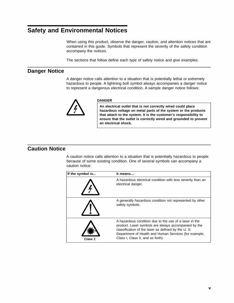
Danger NoticeA danger notice calls attention to a situation that is potentially lethal or extremelyhazardous to people. A lightning bolt symbol always accompanies a danger noticeto represent a dangerous electrical condition. A sample danger notice follows:
DANGER
An electrical outlet that is not correctly wired could placehazardous voltage on metal parts of the system or the productsthat attach to the system. It is the customer’s responsibility toensure that the outlet is correctly wired and grounded to preventan electrical shock.
Caution NoticeA caution notice calls attention to a situation that is potentially hazardous to peoplebecause of some existing condition. One of several symbols can accompany acaution notice:
If the symbol is... It means....
A hazardous electrical condition with less severity than anelectrical danger.
A generally hazardous condition not represented by othersafety symbols.
A hazardous condition due to the use of a laser in theproduct. Laser symbols are always accompanied by theclassification of the laser as defined by the U. S.Department of Health and Human Services (for example,Class I, Class II, and so forth).
v

Sample caution notices follow:
CAUTION:The controller card contains a lithium battery. To avoid possibleexplosion, do not burn, exchange, or charge the battery. Discard thecontroller card as instructed by local regulations for lithiumbatteries.
CAUTION:Do not attempt to use the handle on the module to lift the entiredevice (module and enclosure) as a unit. First remove the module;then, use two hands to lift the enclosure.
Attention NoticeAn attention notice indicates the possibility of damage to a program, device, orsystem (server), or to data. An exclamation point symbol may accompany anattention notice, but is not required. Sample attention notices follow:
Attention: If you use a power screwdriver to perform thisprocedure it could destroy the tape.
Attention: Do not operate the Ultrium Tape Drive in a poor air qualityenvironment.
Laser Safety and ComplianceThese products contain components that comply with performance standards thatare set by the U.S. Food and Drug Administration (Part 21CFR, 1040.10/11). Thismeans that these products belong to a class of laser products that do not emithazardous laser radiation. This classification was accomplished by providing thenecessary protective housing and scanning safeguards to ensure that laserradiation is inaccessible during operation or is within Class I limits. External safetyagencies have reviewed these products and have obtained approvals to the lateststandards as they apply to this product type.
vi IBM Ultrium Internal Tape Drive
|
|

Summary of Changes
This section summarizes the changes that are contained in each edition of thisbook.
Second EditionThis edition includes information about attaching the Ultrium Tape Drive ModelT200F, which features a Fibre Channel interface. Fibre Channel technologyincreases the maximum server-to-tape-drive distance by using fiber optic cables. Inaddition, Storage Area Network (SAN) components greatly extend the maximumdistance and the Fibre Channel topologies.
Third EditionThis edition removes references to the StorageSmart™ by IBM brand and addsclarifications to sections of text.
vii
||
|||||
||

viii IBM Ultrium Internal Tape Drive

Chapter 1. Introduction
The IBM Ultrium Internal Tape Drive Models T200 and T200F are high-performance,high-capacity data-storage devices that can be integrated into an enclosure, suchas a desktop unit, tape cartridge autoloader, or tape library. The tape drives aredesigned to perform unattended backups, as well as retrieve and archive files.Table 1 outlines the features of the Models T200 and T200F. Figure 1 is a front viewof the drive with and without a bezel.
Table 1. Features of the IBM Ultrium Internal Tape Drive
Model T200 - SCSI Drive Model T200F - Fibre Channel Drive
Native storage capacity of up to 100 GB per cartridge1 (200 GB assuming 2:1 datacompression)
Native sustained data transfer rate of 15 MB per second2 (30 MB assuming 2:1 datacompression)
RS-422 interface for enhanced performance in automated tape libraries
Burst data transfer rate of 80 MB persecond
Burst data transfer rate of 100 MB per second
Ultra2 SCSI Low Voltage Differential/SingleEnded (LVD/SE)
SC-Duplex, multimode optical connector withthe use of SCSI protocol
J1 connector (for SCSI signals, SCSI IDselection, and power connection)
Attachment to Storage Area Network (SAN)components
The Ultrium Internal Tape Drive uses a data compression algorithm known asLTO-DC (LTO Data Compression). A key difference between LTO-DC and previouscompression algorithms is that record boundaries and file marks are encoded ascontrol symbols in LTO-DC. LTO-DC detects them, but it will not recompress andtest them. Another difference is that LTO-DC allows switching between compressionand no compression within the data stream. This feature prevents the data fromexpanding when the drive compresses random or encrypted data.
IBM offers device drivers for the Ultrium Tape Drive. Device drivers enable the driveto interact with a variety of servers. To properly install an IBM device driver (if
1. 1 GB = one gigabyte or 1 000 000 000 bytes
2. 1 MB = one megabyte or 1 000 000 bytes
A6
7E
00
44
Figure 1. View of Drive With and Without Bezel
1
||
||||
|||
|

required), refer to the IBM Ultrium Device Drivers Installation and User’s Guide. Forapplications that use other device drivers, see the application’s documentation todetermine which drivers to use.
In addition to using IBM tape cartridges with up to 100 GB capacity, the UltriumTape Drive also offers read/write capability for certified LTO Ultrium tape cartridgesthat have capacities of 50 GB, 30 GB, and 10 GB.
The Ultrium Tape Drive records by using a linear, serpentine recording method on1/2-inch, magnetic tape.
SCSI AttachmentThe Ultrium Internal Tape Drive Model T200 uses a SCSI interface and attaches tothe following servers. For specific instructions about attachment, see the IBMUltrium Device Drivers Installation and User’s Guide.
Supported Servers Supported Operating Systems
IBM AS/400® or IBM Eserver iSeries™ OS/400® Level V4R4 or later
IBM RS/6000®, IBM RS/6000 SP™, or IBMEserver pSeries™
AIX® 4.3.3 or 5.1
Hewlett-Packard HP-UX 11.0 PCI 64-bit or HP-UX 11i
SUN® Solaris Version 2.6, 7, or 8
Intel®-compatible servers Microsoft® Windows 2000® Level 2195 orlater, or Windows NT® Server Version 4 withService Pack 6 or later
Red Hat® Linux® 7.1 kernel 2.4.2-2
Physical Characteristics of the SCSI InterfaceThe Ultrium Tape Drive Model T200 contains one SCSI port for attachment to theserver. The SCSI connections and terminations are contained in the single J1connector. The J1 connector contains the connections for the SCSI signals andgrounds, the setting of the SCSI ID, the setting of the SCSI bus termination control,and the connection for the drive power and ground.
The Ultrium Tape Drive Model T200 supports differential SCSI cables withhigh-density, 68-pin connectors. All cables are for field or plant installation, and areavailable in the following lengths:
v 0.5 m (1.6 ft)
v 5.0 m (16 ft)
v 10 m (32 ft)
v 25 m (82 ft)
To order a cable, see “Appendix A. Tools and Supplies” on page 81.
Address AssignmentsFor enhanced functions in automated library systems, the SCSI drive contains anRS-422 interface. If the drive is connected to a library, its SCSI address can be setthrough the RS-422 interface.
Another option to setting the SCSI address is by attaching jumpers to the SCSI IDconnector (see “Step 4. Set the SCSI ID (SCSI Drive Only)” on page 14).
2 IBM Ultrium Internal Tape Drive
|||
||
||
|
||||
|
||
|||
|
|
|
|
|
|

Installing, Removing, or Resetting a Drive on an Active SCSI BusAttaching a drive to an active SCSI bus is supported. However, the preferred andsafest method of adding, removing, or resetting a drive is to power-off the system.
When adding, removing, or resetting a drive on an active SCSI bus, perform thefollowing steps:
1. Quiesce the drive. The drive to be added, removed, or reset must not beinvolved in any bus activity.
2. Disconnect power to the drive.
3. Connect or disconnect the SCSI bus cables to or from the drive’s SCSIconnector. Ensure that the SCSI bus remains intact from the server (initiator) tothe terminator throughout the connection or disconnection process.
Note: Changing or moving the terminator disrupts the continuity of the SCSIbus and interrupts any process on the bus.
Fibre Channel Attachment
Attention: A Class I laser assembly, in the optical transceiver, ismounted on the Ultrium Fibre Channel electronics card. This laserassembly is registered with the Department of Health and HumanServices and is in compliance with IEC825.
The Ultrium Tape Drive Model T200F has one Fibre Channel interface (also called aport). In accordance with the standards of the American National Standards Institute(ANSI), the port runs Fibre Channel Protocol (which includes SCSI commands onthe Fibre Channel) with ANSI-defined Fibre Channel Tape Support. You can attachthe Fibre Channel port to the following servers and SAN components. For additionalinformation about the Fibre Channel connectivity, visit the web athttp://www.ibm.com/storage/storagesmart/lto. To obtain information aboutadapters and operating systems, visit the web at http://www.storage.ibm.com/lto.
Supported Servers Supported Operating Systems
IBM AS/400 or IBM Eserver iSeries OS/400 Level V5R1 or later
IBM RS/6000, IBM RS/6000 SP, or IBMEserver pSeries
AIX 4.3.3 with APARs IY10452 and IY15766,or AIX 5.1
Hewlett-Packard HP-UX 11.0
SUN Solaris Version 2.6, 7, or 8
Intel-compatible servers Microsoft Windows 2000 Level 2195 or later,or Windows NT Server Version 4 withService Pack 6a or later
Supported SAN Components
IBM 2103 Fibre Channel hub (distance solution, only one target per hub)
IBM 2109 Fibre Channel switches
Chapter 1. Introduction 3
||
|
||
|
|||
||
|
||
|||
||
||
||
||||
|
|
|

Physical Characteristics of the Fibre Channel InterfaceThe Ultrium Tape Drive Model T200F attaches to Open Systems servers by usingshort-wave, multimode fiber optic cables. All cables feature SC-duplex connectorsand are designated as 50/125 (50 refers to the diameter of the optical fiber and 125refers to the diameter of the cable; both are measured in micrometers). All cablesare for field or plant installation, and are available in the following lengths:
v 0.5 m (1.6 ft)
v 13 m (43 ft)
v 25 m (82 ft)
v 61 m (200 ft)
v Custom-length fiber cable
You can order fiber cables for specific lengths (other than lengths with featurecodes) by using part number 54G3391. The maximum length is 500 m (1640 ft).Cable length is measured from the drive’s Fibre Channel port. To order a cable, see“Appendix A. Tools and Supplies” on page 81.
Supported TopologiesThe drive supports Two-node Arbitrated Loop and Two-node Switched Fabric Looptopologies.
Two-node Arbitrated LoopThe drive supports the arbitrated loop topology, but only two nodes are supportedon a loop.
Two-node Switched Fabric LoopTwo or more Fibre Channel end points interconnect through a switch. Theseswitches must have loop-attachment capability. Two nodes are supported on eachfabric loop.
Address AssignmentsEach device on a Fibre Channel loop must have a Loop Identifier (LID) and acorresponding Arbitrated Loop Physical Address (AL_PA) to communicate with otherdevices in the topology. The AL_PA identifies the device on the loop. (LIDs and theircorresponding AL_PAs are listed in Table 3 on page 17 and Table 4 on page 18.)You can set an AL_PA by using one of two methods known as soft addressing orhard addressing.
Soft addressing allows the drive to dynamically arbitrate the AL_PA with other FibreChannel devices on the loop. Hard addressing allows you to choose the LID, whichdetermines the corresponding AL_PA. The higher the AL_PA, the lower the priorityof the device.
Generally, servers (initiators) require that devices use hard addressing; they do notsupport soft addressing. When setting addresses, assign the lowest AL_PA (andthus the highest priority) to the server; assign the highest AL_PA (and thus thelowest priority) to the drive.
To set soft or hard addressing, you must place jumpers on designated pins in thedrive’s LID/status connector (see (�2� in Figure 3 on page 11). The pin configurationfor soft and hard addressing is defined in “Step 6. Set the Arbitrated Loop PhysicalAddress (Fibre Channel Drive Only)” on page 15.
4 IBM Ultrium Internal Tape Drive
|||||
|
|
|
|
|
||||
|
||||||
||||
||||
||||
World Wide NamesEach Ultrium Tape Drive has an 8-byte World Wide Name that is assigned by IBMManufacturing. The World Wide Name identifies physical drive ports. An enclosurequeries the World Wide Name through the RS-422 interface; a server queries theName through the Fibre Channel interface. The Ultrium Tape Drive reports theWorld Wide Name to switches. You can use the World Wide Name to uniquelyidentify the drive on a SAN.
Installing, Removing, or Resetting a Drive on an Active Fibre ChannelA Fibre Channel network supports dynamic drive attachment. When adding,removing, or resetting a drive on an active server or SAN, perform the followingsteps:
1. Quiesce the drive. The drive to be added, removed, or reset must not beinvolved in activity.
2. Connect or disconnect the Fibre Channel cables to or from the drive.
Chapter 1. Introduction 5
|
||||||
|||
||
|

6 IBM Ultrium Internal Tape Drive

Chapter 2. Specifications
Table 2 gives the physical, power, and environmental specifications for the UltriumInternal Tape Drive.
Table 2. Specifications for the Ultrium Internal Tape Drive
SpecificationModel T200
with SCSI InterfaceModel T200F
with Fibre Channel Interface
Width 146 mm (5.75 in.) without bezel
148 mm (5.83 in.) with bezel
146 mm (5.75 in.) without bezel
148 mm (5.83 in.) with bezel
Length 206.5 mm (8.13 in.) without bezel
212.5 mm (8.37 in.) with bezel
206.5 mm (8.13 in.) without bezel
212.5 mm (8.37 in.) with bezel
Height 82.5 mm (3.25 in.) without bezel
84.5 mm (3.33 in.) with bezel
82.5 mm (3.25 in.) without bezel
84.5 mm (3.33 in.) with bezel
Weight 3 kg (6 lb 10 oz) 3 kg (6 lb 10 oz)
Voltage (see Note 1) + 5 Vdc and + 12 Vdc (±10%) + 5 Vdc and + 12 Vdc (±10%)
Current for 5 Vdc 4.7 A (typical)
5.0 A (maximum at steady state)
5.0 A (typical)
5.4 A (maximum for 4 ms)
Current for 12 Vdc 1.4 A (typical)
2.3 A (maximum for 300 ms)
1.1 A (typical)
2.3 A (maximum for 300 ms)
Power 41 W (typical)
47 W (maximum for 300 ms)
38 W (typical)
47 W (maximum for 300 ms)
Maximum altitude 3048 m (10,000 ft) 3048 m (10,000 ft)
Environmental Specifications
Environmental Factor Operating Storage Shipping
Drive temperature10 to 40°C
(50 to 104°F)
−40 to 60°C
(−40 to 140°F)
−40 to 60°C
(−40 to 140°F)
Recommended enclosuretemperature (see Note 2)
10 to 42°C
(50 to 108°F)Not applicable Not applicable
Relative humidity 20 to 80% 10 to 90% 10 to 90%
Wet bulb temperature26°C
(79°F)
26°C
(79°F)
26°C
(79°F)
Notes:
1. The + 5 Vdc and + 12 Vdc maximum currents do not occur simultaneously. The Ultrium Tape Drive monitorsvoltage and reports problems to the server.
2. The Ultrium Tape Drive features a temperature sensor indicator that acts as an alert when the drive exceeds therecommended temperature. The set point of the temperature indicator is between 45 and 48°C. To clear theindicator, lower the environmental temperature or clear the air passages of the drive, then reset the drive.
7
||
|||
||
|
|
|
||
|
|
|
|
||
||||

8 IBM Ultrium Internal Tape Drive

Chapter 3. Installing the Tape Drive
Attention:To avoid static electricity damage when you handle the Ultrium Internal TapeDrive, use the following precautions:
v Limit your movement. Movement can cause static electricity to build aroundyou.
v Always handle the Ultrium Tape Drive carefully. Handle adapters by theedges. Never touch exposed circuitry.
v Prevent others from touching the Ultrium Tape Drive.
v Before you unpack and install the Ultrium Tape Drive into an enclosure,touch its static-protective packaging to an unpainted metal surface on theenclosure for at least 2 seconds. This reduces static electricity in thepackaging and your body.
v When possible, remove the Ultrium Tape Drive from its static-protectivepackaging and install it directly into an enclosure without setting it down.When this is not possible, place the tape drive’s packaging on a smooth,level surface and place the tape drive on the packaging.
v Do not place the Ultrium Tape Drive on the cover of the enclosure or on anyother metal surface.
The steps that follow describe how to install the Ultrium Tape Drive.
Note: Depending on the type of enclosure, installation procedures may vary. Beforestarting this installation, read these instructions and compare them to thedrive installation instructions for your enclosure.
When installing the Ultrium Tape Drive into an enclosure, refer to “Rear View of theSCSI Drive” on page 10 or “Rear View of the Fibre Channel Drive” on page 11.
9
|
||
|||
||
||
|
||||
||||
||
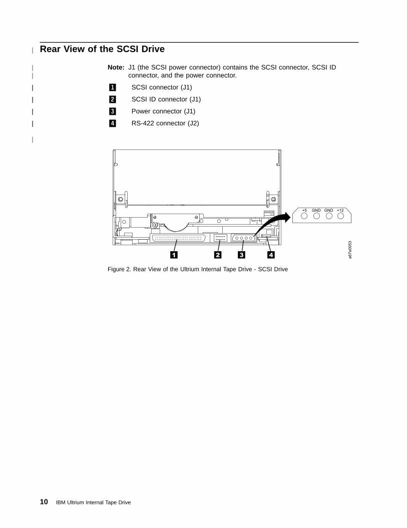
Rear View of the SCSI Drive
Note: J1 (the SCSI power connector) contains the SCSI connector, SCSI IDconnector, and the power connector.
�1� SCSI connector (J1)
�2� SCSI ID connector (J1)
�3� Power connector (J1)
�4� RS-422 connector (J2)
Figure 2. Rear View of the Ultrium Internal Tape Drive - SCSI Drive
10 IBM Ultrium Internal Tape Drive
|
||
||
||
||
||
|
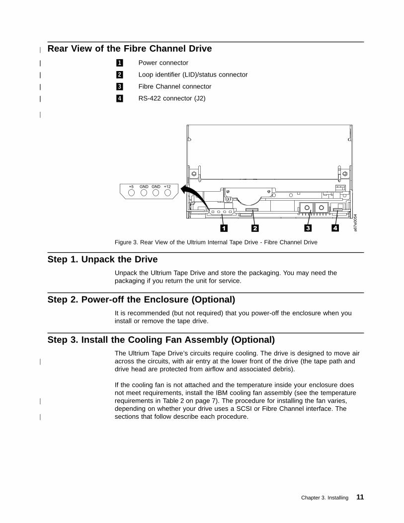
Rear View of the Fibre Channel Drive�1� Power connector
�2� Loop identifier (LID)/status connector
�3� Fibre Channel connector
�4� RS-422 connector (J2)
Step 1. Unpack the DriveUnpack the Ultrium Tape Drive and store the packaging. You may need thepackaging if you return the unit for service.
Step 2. Power-off the Enclosure (Optional)It is recommended (but not required) that you power-off the enclosure when youinstall or remove the tape drive.
Step 3. Install the Cooling Fan Assembly (Optional)The Ultrium Tape Drive’s circuits require cooling. The drive is designed to move airacross the circuits, with air entry at the lower front of the drive (the tape path anddrive head are protected from airflow and associated debris).
If the cooling fan is not attached and the temperature inside your enclosure doesnot meet requirements, install the IBM cooling fan assembly (see the temperaturerequirements in Table 2 on page 7). The procedure for installing the fan varies,depending on whether your drive uses a SCSI or Fibre Channel interface. Thesections that follow describe each procedure.
Figure 3. Rear View of the Ultrium Internal Tape Drive - Fibre Channel Drive
Chapter 3. Installing 11
|
||
||
||
||
|
|
|
|

Installing the Cooling Fan onto a SCSI DriveTo install the optional cooling fan assembly onto an Ultrium Tape Drive that uses aSCSI interface:1. Remove and discard the two cover screws from the rear of the Ultrium Tape
Drive (see �1� in Figure 4). Use a Phillips screwdriver to remove the screws.2. Position the fan shroud �2� at the rear of the drive and align its top with the top
of the drive.3. Attach the fan shroud to the rear of the drive by securing the two captured
screws �3� with a Phillips screwdriver.4. Connect the SCSI bus cable �4� to the connector at the rear of the SCSI drive.5. Attach one end of the Y-cable �5� to the drive’s power connector.6. Attach the fan cover assembly �6� to the fan shroud �2� by securing four
screws �7� with a Phillips screwdriver.7. Connect the other end of the Y-cable �8� to the fan assembly’s power connector
�9�.8. Connect the Y-cable �10� to the power supply in the enclosure.
Figure 4. Installing the Cooling Fan Assembly onto a SCSI Drive
12 IBM Ultrium Internal Tape Drive
|
||||||||

Installing the Cooling Fan onto a Fibre Channel DriveTo install the optional cooling fan assembly onto an Ultrium Tape Drive that uses aFibre Channel interface:1. Remove and discard the two cover screws from the rear of the Ultrium Tape
Drive (see �1� in Figure 5). Use a Phillips screwdriver to remove the screws.2. Position the fan shroud �2� at the rear of the drive and align its top with the top
of the drive.3. Attach the fan shroud to the rear of the drive by securing the two captured
screws �3� with a Phillips screwdriver.4. Connect the fiber optic cable �4� to the connector at the rear of the Fibre
Channel drive.5. Attach one end of the Y-cable �5� to the drive’s power connector.6. Attach the fan cover assembly �6� to the fan shroud �2� by securing four
screws �7� with a Phillips screwdriver.7. Connect the other end of the Y-cable �8� to the fan assembly’s power connector
�9�.8. Connect the Y-cable �10� to the power supply in the enclosure.
Figure 5. Installing the Cooling Fan Assembly onto a Fibre Channel Drive
Chapter 3. Installing 13
|
|||||||||
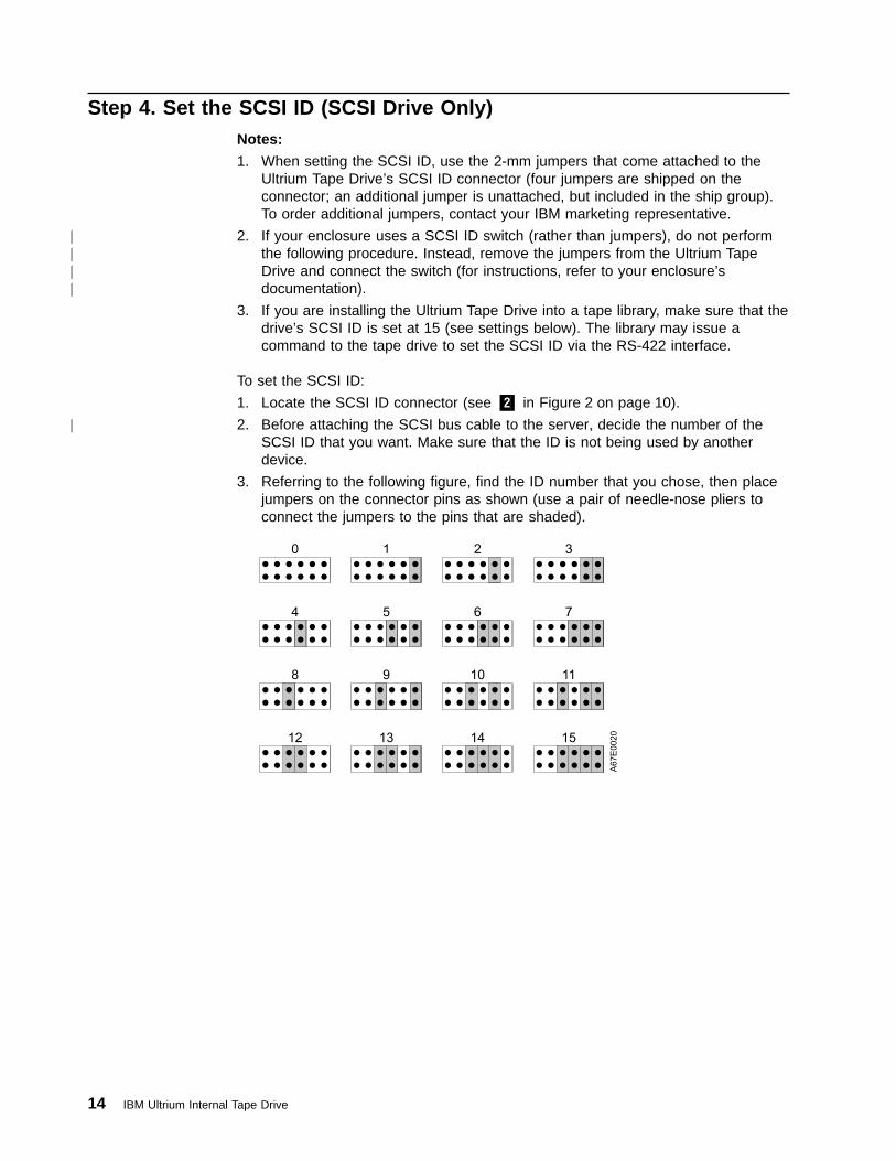
Step 4. Set the SCSI ID (SCSI Drive Only)Notes:
1. When setting the SCSI ID, use the 2-mm jumpers that come attached to theUltrium Tape Drive’s SCSI ID connector (four jumpers are shipped on theconnector; an additional jumper is unattached, but included in the ship group).To order additional jumpers, contact your IBM marketing representative.
2. If your enclosure uses a SCSI ID switch (rather than jumpers), do not performthe following procedure. Instead, remove the jumpers from the Ultrium TapeDrive and connect the switch (for instructions, refer to your enclosure’sdocumentation).
3. If you are installing the Ultrium Tape Drive into a tape library, make sure that thedrive’s SCSI ID is set at 15 (see settings below). The library may issue acommand to the tape drive to set the SCSI ID via the RS-422 interface.
To set the SCSI ID:
1. Locate the SCSI ID connector (see �2� in Figure 2 on page 10).
2. Before attaching the SCSI bus cable to the server, decide the number of theSCSI ID that you want. Make sure that the ID is not being used by anotherdevice.
3. Referring to the following figure, find the ID number that you chose, then placejumpers on the connector pins as shown (use a pair of needle-nose pliers toconnect the jumpers to the pins that are shaded).
14 IBM Ultrium Internal Tape Drive
||||
|

Step 5. Terminate the Drive and Supply TERMPOWER (SCSI DriveOnly)
If the tape drive is the last device on the SCSI bus, you must terminate the busoutside the enclosure or internally at the SCSI ID connector (see �2� in Figure 2 onpage 10).
To terminate the bus internally, locate one of the five jumpers shipped with theUltrium Tape Drive and place it on the SCSI ID connector as shown in the followingfigure. Place the jumper on the pins that are shaded.
To supply TERMPOWER to the bus, locate one of the five jumpers shipped with theUltrium Tape Drive and place it on the SCSI ID connector as shown in the followingfigure. Place the jumper on the pins that are shaded.
A6
7E
00
49
Step 6. Set the Arbitrated Loop Physical Address (Fibre Channel DriveOnly)
Each device on a Fibre Channel loop must have an Arbitrated Loop PhysicalAddress (AL_PA) to communicate. The AL_PA identifies the device on the loop. Toset the Ultrium Tape Drive’s AL_PA, you must place jumpers on specific pins in thedrive’s loop identifier (LID)/status connector. The placement of the jumpers indicateswhether you want to choose the LID yourself (each LID corresponds to a specificAL_PA) or whether you want the drive to choose the AL_PA by arbitrating it withother devices on the loop. Valid LIDs and their corresponding AL_PAs are providedin this section.
Note: A Loop ID is part of a contiguous range of values; valid AL_PA values arenot in a contiguous range.
In addition to establishing the AL_PA, by moving Feature Switch 3 on the drive toON or off, you can set the drive so that it provides one of the following functions:
v Status about the Fibre Channel loop (through the use of external indicators in anenclosure)
v Additional LIDs
The sections that follow describe how to select the AL_PA. They also describe howto set Feature Switch 3 so that the drive gives status about the loop or providesadditional LIDs.
Chapter 3. Installing 15
|
||||||||
||
||
||
|
|||
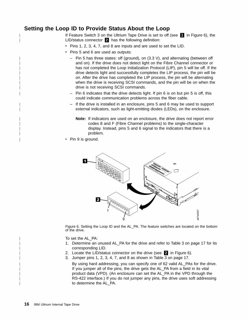
Setting the Loop ID to Provide Status About the LoopIf Feature Switch 3 on the Ultrium Tape Drive is set to off (see �1� in Figure 6), theLID/status connector �2� has the following definition:
v Pins 1, 2, 3, 4, 7, and 8 are inputs and are used to set the LID.
v Pins 5 and 6 are used as outputs:
– Pin 5 has three states: off (ground), on (3.3 V), and alternating (between offand on). If the drive does not detect light on the Fibre Channel connector orhas not completed the Loop Initialization Protocol (LIP), pin 5 will be off. If thedrive detects light and successfully completes the LIP process, the pin will beon. After the drive has completed the LIP process, the pin will be alternatingwhen the drive is receiving SCSI commands, and the pin will be on when thedrive is not receiving SCSI commands.
– Pin 6 indicates that the drive detects light. If pin 6 is on but pin 5 is off, thiscould indicate communication problems across the fiber cable.
– If the drive is installed in an enclosure, pins 5 and 6 may be used to supportexternal indicators, such as light-emitting diodes (LEDs), on the enclosure.
Note: If indicators are used on an enclosure, the drive does not report errorcodes 8 and F (Fibre Channel problems) to the single-characterdisplay. Instead, pins 5 and 6 signal to the indicators that there is aproblem.
v Pin 9 is ground.
To set the AL_PA:1. Determine an unused AL_PA for the drive and refer to Table 3 on page 17 for its
corresponding LID.2. Locate the LID/status connector on the drive (see �2� in Figure 6).3. Jumper pins 1, 2, 3, 4, 7, and 8 as shown in Table 3 on page 17.
By using hard addressing, you can specify one of 62 valid AL_PAs for the drive.If you jumper all of the pins, the drive gets the AL_PA from a field in its vitalproduct data (VPD). (An enclosure can set the AL_PA in the VPD through theRS-422 interface.) If you do not jumper any pins, the drive uses soft addressingto determine the AL_PA.
a6
7e
00
47
1
2
1
9
Figure 6. Setting the Loop ID and the AL_PA. The feature switches are located on the bottomof the drive.
16 IBM Ultrium Internal Tape Drive
||
|||||||
|
||
||||
|
|||||
|||||
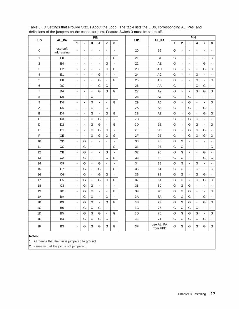
Table 3. ID Settings that Provide Status About the Loop. The table lists the LIDs, corresponding AL_PAs, anddefinitions of the jumpers on the connector pins. Feature Switch 3 must be set to off.
LID AL_PAPIN
LID AL_PAPIN
1 2 3 4 7 8 1 2 3 4 7 8
0use soft
addressing- - - - - - 20 B2 G - - - - -
1 E8 - - - - - G 21 B1 G - - - - G
2 E4 - - - - G - 22 AE G - - - G -
3 E2 - - - - G G 23 AD G - - - G G
4 E1 - - - G - - 24 AC G - - G - -
5 E0 - - - G - G 25 AB G - - G - G
6 DC - - - G G - 26 AA G - - G G -
7 DA - - - G G G 27 A9 G - - G G G
8 D9 - - G - - - 28 A7 G - G - - -
9 D6 - - G - - G 29 A6 G - G - - G
A D5 - - G - G - 2A A5 G - G - G -
B D4 - - G - G G 2B A3 G - G - G G
C D3 - - G G - - 2C 9F G - G G - -
D D2 - - G G - G 2D 9E G - G G - G
E D1 - - G G G - 2E 9D G - G G G -
F CE - - G G G G 2F 9B G - G G G G
10 CD - G - - - - 30 98 G G - - - -
11 CC - G - - - G 31 97 G G - - - G
12 CB - G - - G - 32 90 G G - - G -
13 CA - G - - G G 33 8F G G - - G G
14 C9 - G - G - - 34 88 G G - G - -
15 C7 - G - G - G 35 84 G G - G - G
16 C6 - G - G G - 36 82 G G - G G -
17 C5 - G - G G G 37 81 G G - G G G
18 C3 - G G - - - 38 80 G G G - - -
19 BC - G G - - G 39 7C G G G - - G
1A BA - G G - G - 3A 7A G G G - G -
1B B9 - G G - G G 3B 79 G G G - G G
1C B6 - G G G - - 3C 76 G G G G - -
1D B5 - G G G - G 3D 75 G G G G - G
1E B4 - G G G G - 3E 74 G G G G G -
1F B3 - G G G G G 3Fuse AL_PAfrom VPD
G G G G G G
Notes:
1. G means that the pin is jumpered to ground.
2. - means that the pin is not jumpered.
Chapter 3. Installing 17

Setting the Loop ID to Provide Additional Loop IDsIf Feature Switch 3 on the Ultrium Tape Drive is set to ON (see �1� in Figure 6 onpage 16), the LID/status connector �2� has the following definition:
v Pins 1 through 7 are used to set the LID.
v Pin 8 overrides pins 1 through 7. If pin 8 is jumpered, the drive will use its vitalproduct data (VPD) to set the AL_PA. The enclosure can set the AL_PA in VPDthrough the RS-422 interface.
v Pin 9 is ground.
Note: Feature Switch 3 does not support LEDs on an enclosure. Therefore, whenFeature Switch 3 is set to ON, the drive can report Fibre Channel problems(error codes 8 and F) on the single-character display, but not by using theenclosure’s external indicators.
To set the AL_PA:1. Determine an unused AL_PA address for the drive and refer to Table 4 for its
corresponding LID.2. Locate the LID/status connector on the drive (see �2� in Figure 6 on page 16).3. Jumper pins 1 through 8 as shown in Table 4.
Table 4. ID Settings that Provide Additional Loop IDs. The table lists the LIDs, corresponding AL_PAs, and definitionsof the jumpers on the connector pins. Feature Switch 3 must be set to ON.
LID AL_PAPIN
LID AL_PAPIN
1 2 3 4 5 6 7 1 2 3 4 5 6 7
0 EF - - - - - - - 21 B1 - G - - - - G
1 E8 - - - - - - G 22 AE - G - - - G -
2 E4 - - - - - G - 23 AD - G - - - G G
3 E2 - - - - - G G 24 AC - G - - G - -
4 E1 - - - - G - - 25 AB - G - - G - G
5 E0 - - - - G - G 26 AA - G - - G G -
6 DC - - - - G G - 27 A9 - G - - G G G
7 DA - - - - G G G 28 A7 - G - G - - -
8 D9 - - - G - - - 29 A6 - G - G - - G
9 D6 - - - G - - G 2A A5 - G - G - G -
A D5 - - - G - G - 2B A3 - G - G - G G
B D4 - - - G - G G 2C 9F - G - G G - -
C D3 - - - G G - - 2D 9E - G - G G - G
D D2 - - - G G - G 2E 9D - G - G G G -
E D1 - - - G G G - 2F 9B - G - G G G G
F CE - - - G G G G 30 98 - G G - - - -
10 CD - - G - - - - 31 97 - G G - - - G
11 CC - - G - - - G 32 90 - G G - - G -
12 CB - - G - - G - 33 8F - G G - - G G
13 CA - - G - - G G 34 88 - G G - G - -
14 C9 - - G - G - - 35 84 - G G - G - G
15 C7 - - G - G - G 36 82 - G G - G G -
16 C6 - - G - G G - 37 81 - G G - G G G
18 IBM Ultrium Internal Tape Drive
|
|||
||||
|||||

Table 4. ID Settings that Provide Additional Loop IDs (continued). The table lists the LIDs, corresponding AL_PAs,and definitions of the jumpers on the connector pins. Feature Switch 3 must be set to ON.
LID AL_PAPIN
LID AL_PAPIN
1 2 3 4 5 6 7 1 2 3 4 5 6 7
17 C5 - - G - G G G 38 80 - G G G - - -
18 C3 - - G G - - - 39 7C - G G G - - G
19 BC - - G G - - G 3A 7A - G G G - G -
1A BA - - G G - G - 3B 79 - G G G - G G
1B B9 - - G G - G G 3C 76 - G G G G - -
1C B6 - - G G G - - 3D 75 - G G G G - G
1D B5 - - G G G - G 3E 74 - G G G G G -
1E B4 - - G G G G - 3F 73 - G G G G G G
1F B3 - - G G G G G 40 72 G - - - - - -
20 B2 - G - - - - - 41 71 G - - - - - G
42 6E G - - - - G - 61 39 G G - - - - G
43 6D G - - - - G G 62 36 G G - - - G -
44 6C G - - - - G - 63 35 G G - - - G G
45 6B G - - - G - G 64 34 G G - - G - -
46 6A G - - - G G - 65 33 G G - - G - G
47 69 G - - - G G G 66 32 G G - - G G -
48 67 G - - G - - - 67 31 G G - - G G G
49 66 G - - G - - G 68 2E G G - G - - -
4A 65 G - - G - G - 69 2D G G - G - - G
4B 63 G - - G - G G 6A 2C G G - G - G -
4C 5C G - - G G - - 6B 2B G G - G - G G
4D 5A G - - G G - G 6C 2A G G - G G - -
4E 59 G - - G G G - 6D 29 G G - G G - G
4F 56 G - - G G G G 6E 27 G G - G G G -
50 55 G - G - - - - 6F 26 G G - G G G G
51 54 G - G - - - G 70 25 G G G - - - -
52 53 G - G - - G - 71 23 G G G - - - G
53 52 G - G - - G G 72 1F G G G - - G -
54 51 G - G - G - - 73 1E G G G - - G G
55 4E G - G - G - G 74 1D G G G - G - -
56 4D G - G - G G - 75 1B G G G - G - G
57 4C G - G - G G G 76 18 G G G - G G -
58 4B G - G G - - - 77 17 G G G - G G G
59 4A G - G G - - G 78 10 G G G G - - -
5A 49 G - G G - G - 79 0F G G G G - - G
5B 47 G - G G - G G 7A 08 G G G G - G -
5C 46 G - G G G - - 7B 04 G G G G - G G
5D 45 G - G G G - G 7C 02 G G G G G - -
5E 43 G - G G G G - 7D 01 G G G G G - G
Chapter 3. Installing 19
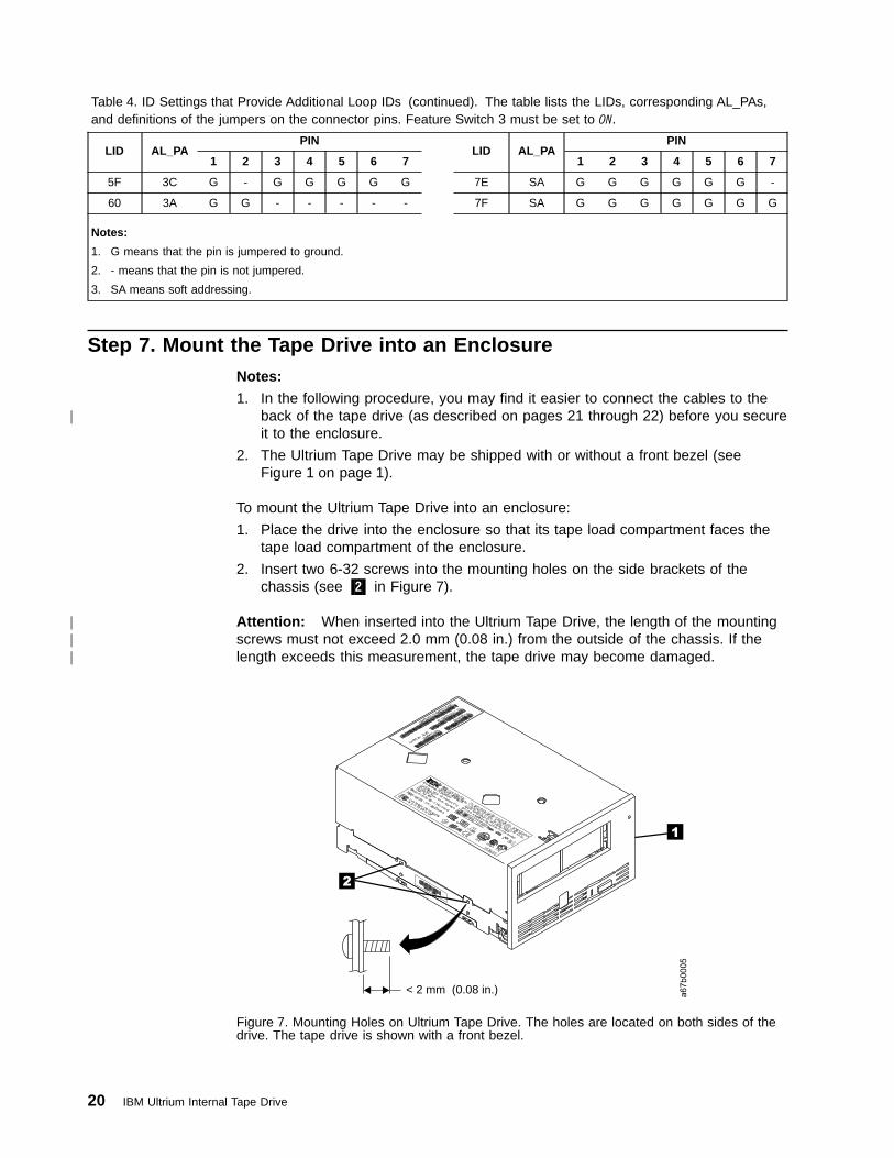
Table 4. ID Settings that Provide Additional Loop IDs (continued). The table lists the LIDs, corresponding AL_PAs,and definitions of the jumpers on the connector pins. Feature Switch 3 must be set to ON.
LID AL_PAPIN
LID AL_PAPIN
1 2 3 4 5 6 7 1 2 3 4 5 6 7
5F 3C G - G G G G G 7E SA G G G G G G -
60 3A G G - - - - - 7F SA G G G G G G G
Notes:
1. G means that the pin is jumpered to ground.
2. - means that the pin is not jumpered.
3. SA means soft addressing.
Step 7. Mount the Tape Drive into an EnclosureNotes:
1. In the following procedure, you may find it easier to connect the cables to theback of the tape drive (as described on pages 21 through 22) before you secureit to the enclosure.
2. The Ultrium Tape Drive may be shipped with or without a front bezel (seeFigure 1 on page 1).
To mount the Ultrium Tape Drive into an enclosure:
1. Place the drive into the enclosure so that its tape load compartment faces thetape load compartment of the enclosure.
2. Insert two 6-32 screws into the mounting holes on the side brackets of thechassis (see �2� in Figure 7).
Attention: When inserted into the Ultrium Tape Drive, the length of the mountingscrews must not exceed 2.0 mm (0.08 in.) from the outside of the chassis. If thelength exceeds this measurement, the tape drive may become damaged.
a67b0005
2
1
< 2 mm (0.08 in.)
Figure 7. Mounting Holes on Ultrium Tape Drive. The holes are located on both sides of thedrive. The tape drive is shown with a front bezel.
20 IBM Ultrium Internal Tape Drive
|
|||

Step 8. Connect Power to the Tape DriveThe Ultrium Tape Drive is designed to be hot-pluggable (that is, you can physicallyinstall the drive into an enclosure without powering the enclosure off). If you installthe drive in a hot-pluggable environment, watch for the indicators to behave asdescribed in step 2.
To connect power to the Ultrium Tape Drive:
1. Connect the enclosure’s internal power cable to the power connector on thedrive (if you are using a SCSI drive, see �3� in Figure 2 on page 10; if you areusing Fibre Channel drive, see �1� in Figure 3 on page 11). Ensure that theconnector is properly keyed.
2. Review the location of the single-character display and the status light on page23 (if your drive does not have a bezel, note that the bulb of the status light isrecessed and the light is not visible until lit). Watch for the following whileturning on the power to the enclosure:
Attention: If the single-character display does not come on, the drivemay not be getting power.
v The single-character display increments, then becomes blank (not lit).
v The status light briefly becomes solid amber, then becomes solid green.
After the single-character display becomes blank, the tape drive is ready for thecheckout procedure in the next step.
Step 9. Perform a Checkout of the Tape DriveTo perform a checkout of the Ultrium Tape Drive:
1. Place the drive in maintenance mode (see “Placing the Drive in MaintenanceMode” on page 27).
2. Run the tape drive diagnostics (Function Code 1 in Table 7 on page 29). If anerror code appears on the single-character display, go to Table 12 on page 53.
3. Run the SCSI or Fibre Channel wrap test to ensure that the interface isfunctional (see Function Code 6 in Table 7 on page 29).
4. Attach an RS-422 wrap plug and run the RS-422 wrap test to ensure that theserial interface is functional (locate Function Code 7 in Table 7 on page 29).
Step 10. Connect the RS-422 Interface
Note: Use this step only if you are installing the Ultrium Tape Drive into anenclosure.
The Ultrium Tape Drive contains an RS-422 interface by which it can communicatewith an enclosure.
To connect the RS-422 interface, connect the RS-422 cable to the J2 connector onthe drive (see �4� in Figure 2 on page 10 and Figure 3 on page 11). Connect theother end of the cable to the enclosure.
Chapter 3. Installing 21
||

Step 11. Connect the Tape Drive to the SCSI or Fibre Channel InterfaceTo connect the Ultrium Tape Drive to a SCSI or Fibre Channel interface, chooseone of the following procedures.
Connecting the Drive to a SCSI InterfaceTo connect the Ultrium Tape Drive Model T200 to the SCSI bus:
1. Connect the enclosure’s internal SCSI bus cable to the SCSI connector on thetape drive (see �1� in Figure 2 on page 10).
2. Run the appropriate SCSI attachment verification procedure on your server (forinstructions, refer to the IBM Ultrium Device Drivers Installation and User’sGuide). If a SCSI error occurs, refer to “Using Sense Data” on page 59.
If you want to power a device on or off while it is connected to the same SCSI busas an Ultrium Tape Drive, you can do so if, during the power-on cycle, you quiesceall devices (including the Ultrium Tape Drive) on the bus.
Connecting the Drive to a Fibre Channel InterfaceTo connect the Ultrium Tape Drive Model T200F to the Fibre Channel interface:
1. Connect the enclosure’s internal fiber cable to the Fibre Channel connector onthe tape drive (see �3� in Figure 3 on page 11).
Note: Model T200F can be ordered with several lengths of fiber cabling, up to61 m (200 ft). For ordering information, see Table 13 on page 81.
2. Run the Fibre Channel wrap test at the end of a cable that does not exceed 250m (820 ft) (see Function Code 6 in Table 7 on page 29). Do not bend the cablemore than a radius of 50.8 mm (2 in.) or the optical fiber may break.
3. Connect the fiber cable to an appropriate attachment (server, switch, or hub).For information about attaching the fiber cable, refer to the documentation foryour server, switch, or hub.
Step 13. Configure the Tape Drive to the Server, Switch, or HubTo configure the tape drive to the server, or to configure the Model T200F FibreChannel drive to a switch or hub, refer to the server’s documentation.
22 IBM Ultrium Internal Tape Drive
|
|
|
|||
|
|
|

Chapter 4. Operating the Tape Drive
Attention: Before operating the Ultrium Internal Tape Drive, let the drive (and anytape cartridges to be inserted) acclimate to the operating environment for 24 hoursor the time necessary to prevent condensation in the drive (the time will vary,depending on the environmental extremes to which the drive was exposed).
When operating the Ultrium Tape Drive, refer to Figure 8 which shows the front ofthe unit.
�1� Status light
�2� Unload button
�3� Single-character display
A67B
0002
1 23
Figure 8. Front View of the Ultrium Internal Tape Drive
23
||

Status LightThe status light (�1� in Figure 8 on page 23) is a light-emitting diode (LED) thatprovides information about the state of the Ultrium Tape Drive. The light can begreen or amber, and (when lit) solid or flashing. Table 5 lists the conditions of thestatus light and provides an explanation of what each condition means.
Table 5. Meaning of Status Light Activity
Color and Conditionof Status Light
Meaning
Off The tape drive has no power or is powered off.
Green/Solid The tape drive is powered on or (if a solid C displays in thesingle-character display) needs cleaning.
Green/Flashing The tape drive is reading from the tape, writing to the tape,rewinding the tape, locating data on the tape, loading the tape, orunloading the tape.
The status light also flashes green if the tape drive contains acartridge during the power-on cycle. In this case, the drivecompletes POST and slowly rewinds the tape (the process maytake approximately 13 minutes). The light stops blinking when thedrive completes the recovery and is ready for a read or writeoperation. To eject the cartridge, press the unload button.
Amber/Solid The tape drive is powering on or is in maintenance mode.
Amber/Flashing One of the following applies:
v If the light flashes once per second, an error occurred and thetape drive or media may require service. Note the code on thesingle-character display, then go to Table 12 on page 53 todetermine the action that is required.
v If the light flashes twice per second, the tape drive is updatingfirmware through the field microcode replacement (FMR) tape, orthe SCSI, Fibre Channel, or RS-422 interface (see “Updating theFirmware” on page 38).
v If the light flashes four times per second, the tape drive detectedan error and is performing a firmware recovery. It resetsautomatically.
24 IBM Ultrium Internal Tape Drive
||||||
||
||

Unload ButtonThe unload button (�2� in Figure 8 on page 23) enables you to perform severalfunctions. Table 6 lists the functions and explains how to initiate them.
Notes:
1. If a function is supported, you may also initiate it through the SCSI, FibreChannel, or RS-422 interface. To determine if a function is supported, refer tothe IBM Ultrium Internal Tape Drive Models T200 and T200F and IBM 3580Ultrium Tape Drive SCSI Reference or refer to the documentation for yourenclosure.
2. When you select a function, the condition of the status light changes toacknowledge the request.
Table 6. Functions that the Unload Button Performs
Function Performedby Unload Button
How to Initiate the Function
Rewind the tape intothe cartridge and ejectthe cartridge from thetape drive
Press the unload button once. The status light flashes green whilethe tape drive is rewinding and unloading.Note: During a rewind and eject operation, the tape drive does notaccept SCSI or Fibre Channel commands from the server.
Place the tape drive inmaintenance mode
Ensure that the tape drive is unloaded. Then, within a 1-secondinterval, push the unload button three times. You are inmaintenance mode when the status light becomes solid amber and0 appears in the single-character display.Note: While in maintenance mode, the tape drive does not acceptSCSI or Fibre Channel commands from the server. The tape drivedoes accept RS-422 interface commands.
Scroll through themaintenance functions
While in maintenance mode, push the unload button once persecond to increment the display characters by one. When youreach the character of the diagnostic or maintenance function thatyou want (see Table 7 on page 29), press and hold the unloadbutton for 3 seconds.
Exit maintenancemode
Press the unload button once per second until 0 displays. Thenpress and hold the unload button for 3 seconds. Maintenance modeis exited when the status light becomes solid green and thesingle-character display becomes blank.
Force a drive dump Attention: If the tape drive detects a permanent error anddisplays an error code, it automatically forces a drive dump (alsoknown as a save of the firmware trace). If you force a drive dump,the existing dump will be overwritten and data will be lost. After youforce a drive dump, do not turn off the power to the tape drive oryou may lose the dump data.
Choose one of the following procedures:v If the tape drive is in maintenance mode (status light is solid
amber), go to Table 7 on page 29 and select Function Code 4.
v If the tape drive is in operating mode (status light is solid orflashing green), press and hold the unload button for 10 seconds.
If captured dump data exists, the tape drive places it into a dumparea (for information about retrieving the data, see “Obtaining aDrive Dump” on page 63).
Reset the drive Press and hold the unload button on the drive for 10 seconds. Thedrive saves the dump, then reboots to allow communication. Do notcycle the power (turn it off, then on), as this will erase the dump’scontents.
Chapter 4. Operating 25
|||||
||
|
|
||||||
|
|
|
|
Single-character DisplayThe Ultrium Tape Drive features an LED (�3� in Figure 8 on page 23) that presentsa single-character code for:
v Diagnostic or maintenance functions
v Error conditions and informational messages
Table 7 on page 29 lists each single-character code that is used for diagnostic ormaintenance functions. Table 12 on page 53 lists the codes for error conditions andinformational messages. If multiple errors occur, the code with the highest priority(represented by the lowest number) displays first. When the error is corrected, thecode with the next highest priority displays, and so on until no errors remain.
The single-character display is blank during normal operation of the tape drive.
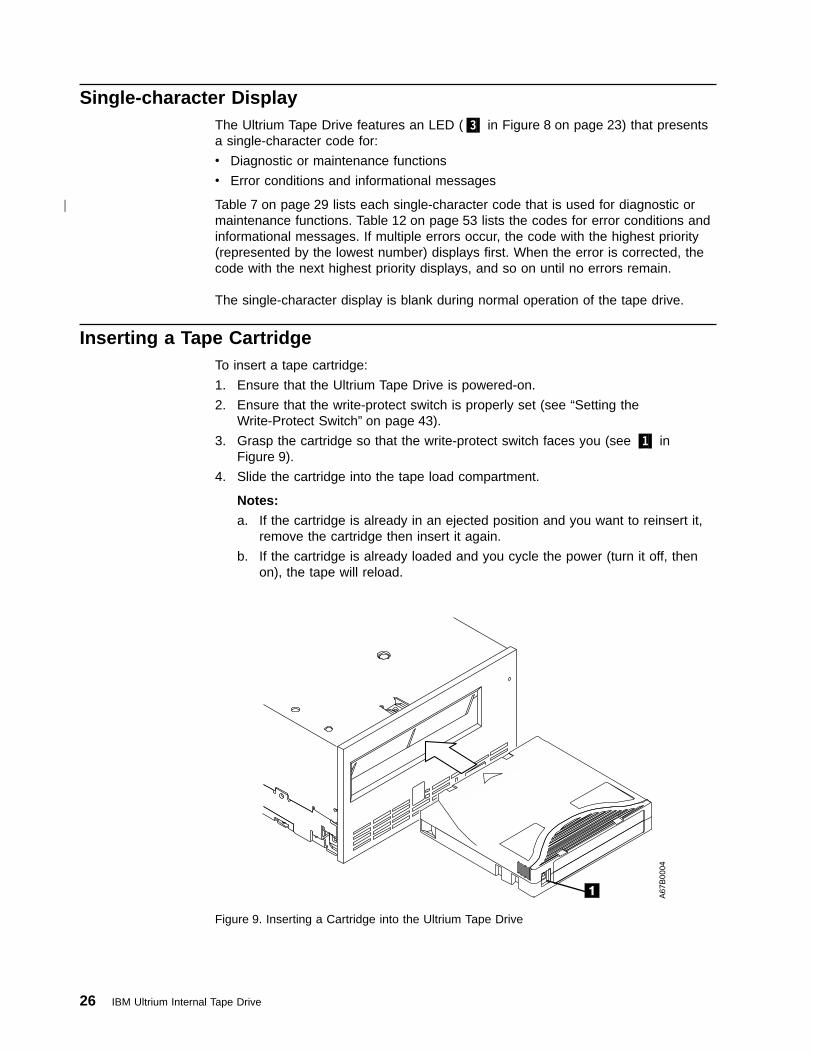
Inserting a Tape CartridgeTo insert a tape cartridge:
1. Ensure that the Ultrium Tape Drive is powered-on.
2. Ensure that the write-protect switch is properly set (see “Setting theWrite-Protect Switch” on page 43).
3. Grasp the cartridge so that the write-protect switch faces you (see �1� inFigure 9).
4. Slide the cartridge into the tape load compartment.
Notes:
a. If the cartridge is already in an ejected position and you want to reinsert it,remove the cartridge then insert it again.
b. If the cartridge is already loaded and you cycle the power (turn it off, thenon), the tape will reload.
A6
7B
00
04
Figure 9. Inserting a Cartridge into the Ultrium Tape Drive
26 IBM Ultrium Internal Tape Drive
|

Removing a Tape CartridgeTo remove a tape cartridge:
1. Ensure that the Ultrium Tape Drive is powered-on.
2. Press the unload button. The drive rewinds the tape and partially ejects thecartridge. The status light flashes green while the tape rewinds, then goes outbefore the cartridge partially ejects.
3. After the cartridge partially ejects, grasp the cartridge and remove it.
If you are unable to remove the cartridge, see “Manually Removing a TapeCartridge” on page 73. Whenever you unload a tape cartridge, the tape drive writesany pertinent information to the cartridge memory.
Cleaning the Drive Head
Attention: To clean the drive head, use the IBM LTO Ultrium Cleaning Cartridgeor an IBM-approved cleaning cartridge.
Clean the drive head whenever C displays on the single-character display and thestatus light is solid green. To clean the head, insert the cleaning cartridge into thetape load compartment (see Figure 9 on page 26). The drive performs the cleaningautomatically. When the cleaning is finished, the drive ejects the cartridge. The IBMLTO Ultrium Cleaning Cartridge is valid for 50 uses.
Placing the Drive in Maintenance ModeThe Ultrium Tape Drive can run diagnostics, verify write and read operations, verifya suspect tape cartridge, update its own firmware, and perform other diagnostic andmaintenance functions listed in Table 7 on page 29. The drive must be inmaintenance mode to perform these functions.
Attention: Maintenance functions cannot be performed concurrently with read orwrite operations. While in maintenance mode, the tape drive does not accept SCSIor Fibre Channel commands from the server. The tape drive does accept RS-422interface commands.
To place the drive in maintenance mode:
1. Make sure that no cartridge is in the drive.
2. Within a 1-second interval, press the unload button three times. The status lightbecomes solid amber, which means that the drive is in maintenance mode.
Note: If a cartridge is in the drive, it will eject the first time that you press theunload button and the drive will not be placed in maintenance mode. Tocontinue placing the drive in maintenance mode, remove the cartridgeand repeat this step.
Chapter 4. Operating 27
|
|||
|
||

Selecting a Diagnostic or Maintenance FunctionTo select a diagnostic or maintenance function:
1. Make sure that no cartridge is in the drive.
2. Within a 1-second interval, press the unload button three times. The status lightbecomes solid amber, which means that the drive is in maintenance mode.
Note: If a cartridge is in the drive, it will eject the first time that you press theunload button and the drive will not be placed in maintenance mode. Tocontinue placing the drive in maintenance mode, remove the cartridgeand repeat this step.
3. In Table 7 on page 29, locate the function that you want and its code.
4. Press the unload button once per second until the code that you want appearsin the single-character display.
Note: If you cycle past the desired code, press the unload button once persecond until the code redisplays.
5. Press and hold the unload button for 3 seconds. The drive performs the functionthat you selected.
v If the diagnostic or function requires you to insert a tape cartridge, C displays.Within 60 seconds, insert a cartridge or the tape drive exits maintenancemode.
v If an invalid or write-protected tape cartridge is inserted, 7 displays. The tapedrive unloads the cartridge and exits maintenance mode.
v If the function completes successfully, 0 temporarily displays, and the driveexits maintenance mode.
Note: Certain diagnostics loop and may need to be ended. To end a loopingdiagnostic, press the unload button. The drive acknowledges therequest by slowing the length of time that the currently displayedcharacter flashes on the single-character display (from twice persecond to once per second). When the loop ends, 0 temporarilydisplays and the drive exits maintenance mode.
v If the function fails, the status light flashes amber, an error code displays, andthe drive exits maintenance mode. To resolve the error, refer to Table 12 onpage 53.
v To reset an error, cycle (remove, then reapply) power to the tape drive.
28 IBM Ultrium Internal Tape Drive
|
||
||||

Table 7. Diagnostic and Maintenance Functions
Function Code 1 - Run Tape Drive Diagnostics
Causes the tape drive to run the following self tests:
v Electrical
v Motors
v Write data flow
v Loop write-to-read
v Sensors
Attention: Insert only a scratch data cartridge for this test. Data on the cartridge will be overwritten.
1. Make sure that no cartridge is in the drive.
2. Within a 1-second interval, press the unload button three times. The status light becomes solid amber, whichmeans that the drive is in maintenance mode.Note: If a cartridge is in the drive, it will eject the first time that you press the unload button. The drive will not beplaced in maintenance mode. To continue placing the drive in maintenance mode, remove the cartridge andrepeat this step.
3. Press the unload button once per second until 1 appears in the single-character display.Note: If you cycle past 1, press the unload button once per second until it redisplays.
4. To select the function, press and hold the unload button for 3 seconds. After you select the function, the driveruns diagnostics for approximately 90 seconds, then C flashes. When C flashes, the drive is waiting for acartridge.
5. Within 60 seconds, insert a scratch data cartridge (or the tape drive exits maintenance mode). After you insert thecartridge, 1 flashes:
v If the diagnostic completes successfully, it begins again and runs for a maximum of 10 times. Each loop takesapproximately 20 minutes to run. After the tenth loop, the diagnostic stops and automatically exits maintenancemode. To halt the diagnostic, press the unload button within the first 20 minutes of the test (or the diagnosticwill run another 20 minutes). The drive acknowledges the request by slowing the length of time that thecurrently displayed character flashes on the single-character display (from twice per second to once persecond). The diagnostic continues to the end of its loop and then stops. The tape drive then displays 0,rewinds and unloads the cartridge, and exits maintenance mode.
v If the diagnostics fail, the status light flashes amber and an error code displays. The tape drive unloads thetape cartridge and exits maintenance mode. To resolve the error, locate the code in Table 12 on page 53.
Chapter 4. Operating 29
||
||
||||||

Table 7. Diagnostic and Maintenance Functions (continued)
Function Code 2 - Update Tape Drive Firmware from FMR Tape
Causes the tape drive to load updated firmware from a field microcode replacement (FMR) tape.
Attention: Do not power-off the tape drive while loading code.
1. Make sure that no cartridge is in the drive.
2. Within a 1-second interval, press the unload button three times. The status light becomes solid amber, whichmeans that the drive is in maintenance mode.Note: If a cartridge is in the drive, it will eject the first time that you press the unload button and the drive will notbe placed in maintenance mode. To continue placing the drive in maintenance mode, remove the cartridge andrepeat this step.
3. Press the unload button once per second until 2 appears in the single-character display.Note: If you cycle past 2, press the unload button once per second until it redisplays.
4. To select the function, press and hold the unload button for 3 seconds. After you select the function, C flashes.When C flashes, the drive is waiting for a cartridge. Within 60 seconds, insert the FMR tape cartridge (or the tapedrive exits maintenance mode). After you insert the cartridge, 2 flashes, the status light flashes amber twice persecond, and the tape drive loads the updated firmware from the FMR tape cartridge into its erasableprogrammable read-only memory (EPROM) area:
v If the update completes successfully, the tape drive rewinds and unloads the FMR tape, resets itself, and isready to use the new firmware.
v If the update fails, the tape drive posts an error code to the single-character display (to resolve the error, seeTable 12 on page 53). The drive then unloads the FMR tape and exits maintenance mode.
Function Code 3 - Create FMR Tape
Causes the tape drive to copy its field microcode replacement (FMR) data to a scratch data cartridge.
Attention: If you select this function, the tape drive will overwrite existing data on the scratch data cartridge.
1. Make sure that no cartridge is in the drive.
2. Within a 1-second interval, press the unload button three times. The status light becomes solid amber, whichmeans that the drive is in maintenance mode.Note: If a cartridge is in the drive, it will eject the first time that you press the unload button and the drive will notbe placed in maintenance mode. To continue placing the drive in maintenance mode, remove the cartridge andrepeat this step.
3. Press the unload button once per second until 3 appears in the single-character display.Note: If you cycle past 3, press the unload button once per second until it redisplays.
4. To select the function, press and hold the unload button for 3 seconds. After you select the function, C flashes.When C flashes, the drive is waiting for a cartridge. Within 60 seconds, insert a scratch data cartridge that is notwrite protected (or the tape drive exits maintenance mode). After you insert the cartridge, 3 flashes and the tapedrive copies the FMR data to the scratch data cartridge:
v If the tape drive creates the FMR tape successfully, it displays 0, rewinds and unloads the new FMR tape, andexits maintenance mode.
v If the tape drive fails to create the FMR tape, it displays 7, unloads the FMR tape, and exits maintenancemode.
30 IBM Ultrium Internal Tape Drive
|
||
||
||
||
||
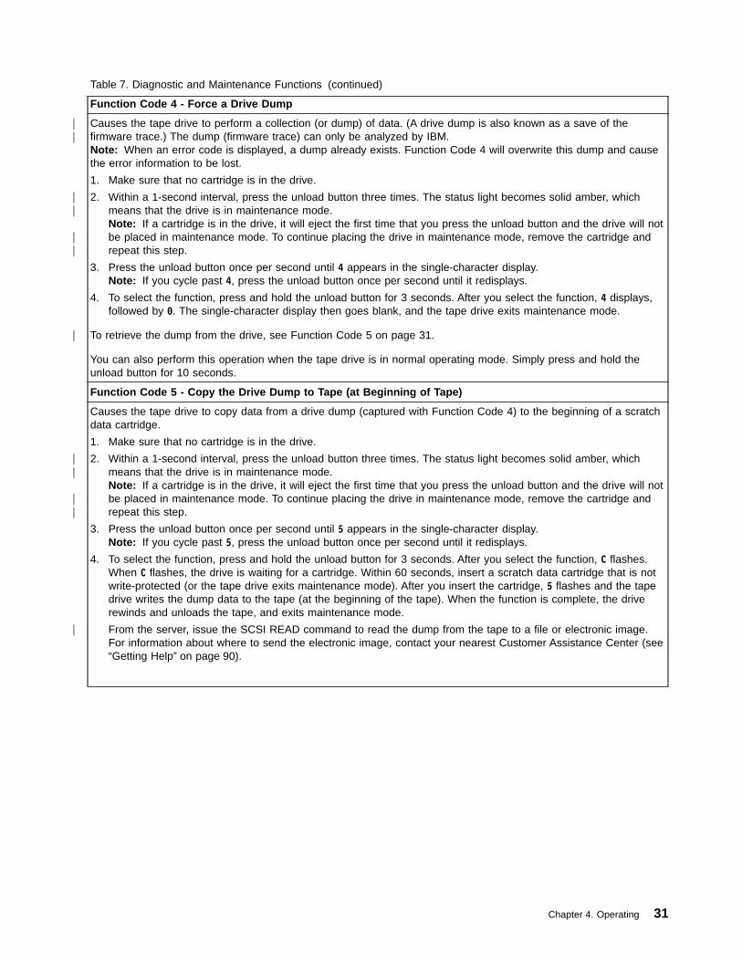
Table 7. Diagnostic and Maintenance Functions (continued)
Function Code 4 - Force a Drive Dump
Causes the tape drive to perform a collection (or dump) of data. (A drive dump is also known as a save of thefirmware trace.) The dump (firmware trace) can only be analyzed by IBM.Note: When an error code is displayed, a dump already exists. Function Code 4 will overwrite this dump and causethe error information to be lost.
1. Make sure that no cartridge is in the drive.
2. Within a 1-second interval, press the unload button three times. The status light becomes solid amber, whichmeans that the drive is in maintenance mode.Note: If a cartridge is in the drive, it will eject the first time that you press the unload button and the drive will notbe placed in maintenance mode. To continue placing the drive in maintenance mode, remove the cartridge andrepeat this step.
3. Press the unload button once per second until 4 appears in the single-character display.Note: If you cycle past 4, press the unload button once per second until it redisplays.
4. To select the function, press and hold the unload button for 3 seconds. After you select the function, 4 displays,followed by 0. The single-character display then goes blank, and the tape drive exits maintenance mode.
To retrieve the dump from the drive, see Function Code 5 on page 31.
You can also perform this operation when the tape drive is in normal operating mode. Simply press and hold theunload button for 10 seconds.
Function Code 5 - Copy the Drive Dump to Tape (at Beginning of Tape)
Causes the tape drive to copy data from a drive dump (captured with Function Code 4) to the beginning of a scratchdata cartridge.
1. Make sure that no cartridge is in the drive.
2. Within a 1-second interval, press the unload button three times. The status light becomes solid amber, whichmeans that the drive is in maintenance mode.Note: If a cartridge is in the drive, it will eject the first time that you press the unload button and the drive will notbe placed in maintenance mode. To continue placing the drive in maintenance mode, remove the cartridge andrepeat this step.
3. Press the unload button once per second until 5 appears in the single-character display.Note: If you cycle past 5, press the unload button once per second until it redisplays.
4. To select the function, press and hold the unload button for 3 seconds. After you select the function, C flashes.When C flashes, the drive is waiting for a cartridge. Within 60 seconds, insert a scratch data cartridge that is notwrite-protected (or the tape drive exits maintenance mode). After you insert the cartridge, 5 flashes and the tapedrive writes the dump data to the tape (at the beginning of the tape). When the function is complete, the driverewinds and unloads the tape, and exits maintenance mode.
From the server, issue the SCSI READ command to read the dump from the tape to a file or electronic image.For information about where to send the electronic image, contact your nearest Customer Assistance Center (see“Getting Help” on page 90).
Chapter 4. Operating 31
||
||
||
|
||
||
|

Table 7. Diagnostic and Maintenance Functions (continued)
Function Code 6 - Run Wrap Test
Causes the drive to perform one of the following:
v A check of the SCSI circuitry from and to the SCSI connector
v A check of the Fibre Channel circuitry from and to the Fibre Channel connector or fiber cable
To run the test, determine whether your drive uses a SCSI or Fibre Channel interface, then choose one of thefollowing procedures.
Running a SCSI Wrap Test
This test evaluates the SCSI circuitry. A SCSI LVD wrap plug (part number 19P0481) is required for this procedure.To order the wrap plug, see “Appendix A. Tools and Supplies” on page 81.
Before you select this function, terminate the SCSI bus and attach a SCSI wrap plug by doing one of the following:
v Place a jumper on pins 5 and 6 of the drive’s SCSI ID connector (as shown by the shaded area in the figurebelow), then attach the SCSI wrap plug to the connector (in place of the SCSI cable).
v Place a jumper on pin 6 of the drive’s SCSI ID connector (as shown by the shaded area in the figure below), thenconnect a Y-cable to the SCSI connector. Connect a terminator to one end of the Y-cable and connect the SCSIwrap plug to the other end of the cable.
A6
7E
00
49
1. Ensure that the drive does not contain a cartridge.
2. Within a 1-second interval, press the unload button three times. The status light becomes solid amber, whichmeans that the drive is in maintenance mode.Note: If a cartridge is in the drive, it will eject the first time that you press the unload button and the drive will notbe placed in maintenance mode. To continue placing the drive in maintenance mode, remove the cartridge andrepeat this step.
3. Press the unload button once per second until 6 appears in the single-character display.Note: If you cycle past 6, press the unload button once per second until it redisplays.
4. To select the function, press and hold the unload button for 3 seconds. After you select the function, the tapedrive automatically starts the test:
v If the test is successful, it loops and begins again. Press the unload button. The test stops, 0 displays, and thetape drive exits maintenance mode. To continue to isolate the problem, go to “Fixing SCSI Bus Errors” onpage 65 and locate the steps to take after you run the SCSI wrap test.
v If the test fails, 8 displays, the test stops, and the tape drive exits maintenance mode. To resolve the error,replace the tape drive (see “Removing the SCSI Tape Drive” on page 71).
32 IBM Ultrium Internal Tape Drive
|
||
|||
|
||||
|
|
||
||
|||
|

Table 7. Diagnostic and Maintenance Functions (continued)
Running a Fibre Channel Wrap Test
This test evaluates the Fibre Channel circuitry at the drive’s Fibre Channel connector, then at the fiber cable. A FibreChannel wrap plug (part number 08L9459, formerly 34L2629) is required for this procedure. To run the wrap testthrough the fiber cable, a duplex adapter is required (part number 19P0242). To order the wrap plug and adapter, see“Appendix A. Tools and Supplies” on page 81. All cables and wrap plugs are hot-pluggable (that is, they can beremoved from or added to the drive while the drive or its enclosure is powered-on).
1. Take all devices on the Fibre Channel offline (for instructions, refer to your server’s documentation).
2. Make sure that no cartridge is in the drive.
3. Disconnect the fibre cable from the drive and replace it with the Fibre Channel wrap plug. (When you disconnectthe cable, the connection to the Fibre Channel loop may break, but will be restored at the end of the procedurewhen you reconnect the cable. For other devices on the loop, operations may temporarily be disrupted.)
Attention: Do not run the wrap test while the drive is connected to a Fibre Channel loop. This could disturbthe Fibre Channel loop and cause performance or I/O problems.
4. Within a 1-second interval, press the unload button three times. The status light becomes solid amber, whichmeans that the drive is in maintenance mode.Note: If a cartridge is in the drive, it will eject the first time that you press the unload button and the drive willnot be placed in maintenance mode. To continue placing the drive in maintenance mode, remove the cartridgeand repeat this step.
5. Press the unload button once per second until 6 appears in the single-character display.Note: If you cycle past 6, press the unload button once per second until it redisplays.
Testing the Circuitry at the Drive’s Fibre Channel Connector
6. To select the function, press and hold the unload button for 3 seconds. After you select the function, the tapedrive automatically starts the test:
v If the test is successful, the circuitry at the drive’s Fibre Channel connector is working properly. The test loopsand begins again. Press the unload button. 0 displays and the tape drive exits maintenance mode. Continueto step 7 to test the fiber cable.
v If the test fails, an error code displays and the status light flashes amber. The test stops and the drive exitsmaintenance mode. To resolve the error, locate the code in Table 12 on page 53.
7. Disconnect the Fibre Channel wrap plug from the drive.Testing the Circuitry at the Fiber Cable
8. Connect the duplex adapter, then the Fibre Channel wrap plug to the end of the fiber cable.Note: The Fibre Channel wrap test can only be run on cable lengths up to 250 meters (820 ft).
9. Within a 1-second interval, press the unload button three times. The status light becomes solid amber, whichmeans that the drive is in maintenance mode.Note: If a cartridge is in the drive, it will eject the first time that you press the unload button and the drive willnot be placed in maintenance mode. To continue placing the drive in maintenance mode, remove the cartridgeand repeat this step.
10. Press the unload button once per second until 6 appears in the single-character display.Note: If you cycle past 6, press the unload button once per second until it redisplays.
11. To select the function, press and hold the unload button for 3 seconds. After you select the function, the tapedrive automatically starts the test:
v If the test is successful, the drive and the cable are working properly. The problem is at the server. To resolvethe error, refer to the service guide for the server.
v If the test fails, replace the fiber cable.
12. Remove the Fibre Channel wrap plug and the duplex adapter, and reconnect the fiber cable.
Chapter 4. Operating 33
|||||
|
|||
||
||
||
|||
||
|
||
||
||
||
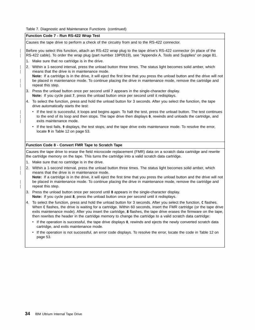
Table 7. Diagnostic and Maintenance Functions (continued)
Function Code 7 - Run RS-422 Wrap Test
Causes the tape drive to perform a check of the circuitry from and to the RS-422 connector.
Before you select this function, attach an RS-422 wrap plug to the tape drive’s RS-422 connector (in place of theRS-422 cable). To order the wrap plug (part number 19P0519), see “Appendix A. Tools and Supplies” on page 81.
1. Make sure that no cartridge is in the drive.
2. Within a 1-second interval, press the unload button three times. The status light becomes solid amber, whichmeans that the drive is in maintenance mode.Note: If a cartridge is in the drive, it will eject the first time that you press the unload button and the drive will notbe placed in maintenance mode. To continue placing the drive in maintenance mode, remove the cartridge andrepeat this step.
3. Press the unload button once per second until 7 appears in the single-character display.Note: If you cycle past 7, press the unload button once per second until it redisplays.
4. To select the function, press and hold the unload button for 3 seconds. After you select the function, the tapedrive automatically starts the test:
v If the test is successful, it loops and begins again. To halt the test, press the unload button. The test continuesto the end of its loop and then stops. The tape drive then displays 0, rewinds and unloads the cartridge, andexits maintenance mode.
v If the test fails, 9 displays, the test stops, and the tape drive exits maintenance mode. To resolve the error,locate 9 in Table 12 on page 53.
Function Code 8 - Convert FMR Tape to Scratch Tape
Causes the tape drive to erase the field microcode replacement (FMR) data on a scratch data cartridge and rewritethe cartridge memory on the tape. This turns the cartridge into a valid scratch data cartridge.
1. Make sure that no cartridge is in the drive.
2. Within a 1-second interval, press the unload button three times. The status light becomes solid amber, whichmeans that the drive is in maintenance mode.Note: If a cartridge is in the drive, it will eject the first time that you press the unload button and the drive will notbe placed in maintenance mode. To continue placing the drive in maintenance mode, remove the cartridge andrepeat this step.
3. Press the unload button once per second until 8 appears in the single-character display.Note: If you cycle past 8, press the unload button once per second until it redisplays.
4. To select the function, press and hold the unload button for 3 seconds. After you select the function, C flashes.When C flashes, the drive is waiting for a cartridge. Within 60 seconds, insert the FMR cartridge (or the tape driveexits maintenance mode). After you insert the cartridge, 8 flashes, the tape drive erases the firmware on the tape,then rewrites the header in the cartridge memory to change the cartridge to a valid scratch data cartridge:
v If the operation is successful, the tape drive displays 0, rewinds and ejects the newly converted scratch datacartridge, and exits maintenance mode.
v If the operation is not successful, an error code displays. To resolve the error, locate the code in Table 12 onpage 53.
34 IBM Ultrium Internal Tape Drive
||
||
||
|||
||
||

Table 7. Diagnostic and Maintenance Functions (continued)
Function Code 9 - Display Error Code Log
Causes the tape drive to display the last 10 error codes, one at a time (the codes are ordered; the most recent ispresented first and the oldest (tenth) is presented last).
1. Make sure that no cartridge is in the drive.
2. Within a 1-second interval, press the unload button three times. The status light becomes solid amber, whichmeans that the drive is in maintenance mode.Note: If a cartridge is in the drive, it will eject the first time that you press the unload button and the drive will notbe placed in maintenance mode. To continue placing the drive in maintenance mode, remove the cartridge andrepeat this step.
3. Press the unload button once per second until 9 appears in the single-character display.Note: If you cycle past 9, press the unload button once per second until it redisplays.
4. To select the function, press and hold the unload button for 3 seconds. After you select the function, press theunload button to view the most recent error code. Press the unload button again to view successive error codes.If you press the unload button for 3 seconds after the tenth error code displays, 0 displays (if there are no errorsin the log) and the drive exits maintenance mode.
Function Code A - Clear Error Code Log
Causes the tape drive to erase the contents of the error code log.
1. Make sure that no cartridge is in the drive.
2. Within a 1-second interval, press the unload button three times. The status light becomes solid amber, whichmeans that the drive is in maintenance mode.Note: If a cartridge is in the drive, it will eject the first time that you press the unload button and the drive will notbe placed in maintenance mode. To continue placing the drive in maintenance mode, remove the cartridge andrepeat this step.
3. Press the unload button once per second until A appears in the single-character display.Note: If you cycle past A, press the unload button once per second until it redisplays.
4. To select the function, press and hold the unload button for 3 seconds. After you select the function, the tapedrive erases all errors from the error code log, displays 0, then exits maintenance mode.
Function Code C - Insert Cartridge into Tape Drive
This function cannot be selected by itself. It relates to other maintenance functions (such as Run Tape DriveDiagnostics or Create FMR Tape) that require an FMR tape cartridge or scratch tape cartridge that is not writeprotected.
Chapter 4. Operating 35
||
||
||
||

Table 7. Diagnostic and Maintenance Functions (continued)
Function Code E - Test Cartridge & Media
Causes the tape drive to perform a Write/Read test (on the edge bands) to ensure that a suspect cartridge and itsmagnetic tape are acceptable. The tape drive takes approximately 10 minutes to run the test.
Attention: Data on the suspect tape will be overwritten.
1. Make sure that no cartridge is in the drive.
2. Within a 1-second interval, press the unload button three times. The status light becomes solid amber, whichmeans that the drive is in maintenance mode.Note: If a cartridge is in the drive, it will eject the first time that you press the unload button and the drive will notbe placed in maintenance mode. To continue placing the drive in maintenance mode, remove the cartridge andrepeat this step.
3. Press the unload button once per second until E appears in the single-character display.Note: If you cycle past E, press the unload button once per second until it redisplays.
4. To select the function, press and hold the unload button for 3 seconds. After you select the function, C flashes.When C flashes, the drive is waiting for a cartridge. Within 60 seconds, insert the suspect data cartridge (or thetape drive exits maintenance mode). After you insert the cartridge, E flashes:
v If no error is detected, the test begins again and runs for a maximum of 10 times. After the tenth loop, the teststops and the drive automatically exits maintenance mode. To halt the test, press the unload button. The driveacknowledges the request by slowing the length of time that the currently displayed character flashes on thesingle-character display (from twice per second to once per second). The test continues to the end of its loopand then stops. The tape drive then displays 0, rewinds and unloads the cartridge, and exits maintenancemode.
v If an error is detected, the tape drive displays 7, unloads the tape cartridge, and exits maintenance mode. Toresolve the error, locate 7 in Table 12 on page 53.
Function Code F - Fast Read/Write Test
Causes the tape drive to perform tests to ensure that the drive can read from and write to tape. This diagnosticperforms fewer tests than the Run Tape Drive Diagnostics test (Function Code 1). The tape drive takes approximatelythree minutes to run the test. The Fast Read/Write Test is not as comprehensive a test and is not recommended forisolating errors between the drive and the media.
Attention: Data on the suspect tape will be overwritten.
1. Make sure that no cartridge is in the drive.
2. Within a 1-second interval, press the unload button three times. The status light becomes solid amber, whichmeans that the drive is in maintenance mode.Note: If a cartridge is in the drive, it will eject the first time that you press the unload button and the drive will notbe placed in maintenance mode. To continue placing the drive in maintenance mode, remove the cartridge andrepeat this step.
3. Press the unload button once per second until F appears in the single-character display.Note: If you cycle past F, press the unload button once per second until it redisplays.
4. To select the function, press and hold the unload button for 3 seconds. After you select the function, C flashes.When C flashes, the drive is waiting for a cartridge. Within 60 seconds, insert the suspect data cartridge (or thetape drive exits maintenance mode). After you insert the cartridge, F flashes.
v If no error is detected, the test begins again and runs for a maximum of 10 times. Each loop takesapproximately 3 minutes to run. After the tenth loop, the test stops and the drive automatically exitsmaintenance mode. To halt the test, press the unload button. The drive acknowledges the request by slowingthe length of time that the currently displayed character flashes on the single-character display (from twice persecond to once per second). The test continues to the end of its loop and then stops. The tape drive thendisplays 0, rewinds and unloads the cartridge, and exits maintenance mode.
v If an error is detected, the tape drive displays an error code, unloads the tape cartridge, and exits maintenancemode. To resolve the error, locate the code in Table 12 on page 53.
36 IBM Ultrium Internal Tape Drive
||
||
||||||
||
||
||||||

Table 7. Diagnostic and Maintenance Functions (continued)
Function Code H - Test Head
Causes the tape drive to perform the Head Resistance Measurements test and a Write/Read test (on the center ofthe tape). The drive runs these tests to ensure that the tape drive’s head and tape-carriage mechanics are workingcorrectly. The tape drive takes approximately 10 minutes to run the test.
1. Make sure that no cartridge is in the drive.
2. Within a 1-second interval, press the unload button three times. The status light becomes solid amber, whichmeans that the drive is in maintenance mode.Note: If a cartridge is in the drive, it will eject the first time that you press the unload button and the drive will notbe placed in maintenance mode. To continue placing the drive in maintenance mode, remove the cartridge andrepeat this step.
3. Press the unload button once per second until H appears in the single-character display.Note: If you cycle past H, press the unload button once per second until it redisplays.
4. To select the function, press and hold the unload button for 3 seconds. After you select the function, C flashes.When C flashes, the drive is waiting for a cartridge. Within 60 seconds, insert a scratch data cartridge (or the tapedrive exits maintenance mode). After you insert the cartridge, H flashes.
v If no error is detected, the test begins again and runs for a maximum of 10 times. Each loop takesapproximately 10 minutes to run. After the tenth loop, the test stops and the drive automatically exitsmaintenance mode. To halt the test, press the unload button. The drive acknowledges the request by slowingthe length of time that the currently displayed character flashes on the single-character display (from twice persecond to once per second). The test continues to the end of its loop and then stops. The tape drive thendisplays 0, rewinds and unloads the cartridge, and exits maintenance mode.
v If an error is detected, the tape drive displays 5, unloads the tape cartridge, and exits maintenance mode. Toresolve the error, locate 5 in Table 12 on page 53.
Exiting Maintenance ModeTo manually exit maintenance mode, press the unload button once per second until0 appears on the single-character display. Press and hold the unload button for 3seconds. The drive exits maintenance mode (the solid amber status light becomessolid green, then turns off).
Chapter 4. Operating 37
||
||
||||||
||

Updating the FirmwareAttention: When updating firmware, do not power-off the tape drive until theupdate is complete, or the firmware may be lost.
Periodically check for updated levels of drive firmware by visiting the web athttp://www.ibm.com/storage/storagesmart/lto. You can update your drive’sfirmware by:
v Obtaining the new firmware image and downloading it to the drive through theSCSI, Fibre Channel, or RS-422 interface
v Loading the firmware from a field microcode replacement (FMR) tape cartridge
For instructions about how to obtain a new firmware image or FMR tape, visit thepreceding web site. To update the firmware, refer to the following sections.
Updating Firmware through the SCSI, Fibre Channel, or RS-422Interface
Attention: SCSI drives and Fibre Channel drives require different firmwareimages.
When you update the tape drive’s firmware by using the SCSI or Fibre Channelinterface, the procedure varies, depending on whether your server uses an IBMtape device driver or a non-IBM tape device driver (such as a driver from Sun,Hewlett-Packard, or Microsoft).
For instructions about updating code from a server that uses an IBM tape devicedriver, refer to the IBM Ultrium Device Drivers Installation and User’s Guide.
To update code from a server that uses a non-IBM tape device driver, refer to thedocumentation for that device driver.
To update code from the RS-422 interface, see your library’s documentation.
38 IBM Ultrium Internal Tape Drive
|||
||
||
|
|
|

Updating the Firmware with an FMR Tape Cartridge
Attention: SCSI drives and Fibre Channel drives require different firmwareimages.
To update the Ultrium Tape Drive’s firmware from an FMR tape cartridge:
1. Ensure that the tape drive is unloaded.
2. Place the drive in maintenance mode by pressing the unload button three timeswithin a 1-second interval. The status light becomes solid amber, which meansthat the drive is in maintenance mode.
3. Press the unload button once per second until 2 displays, then press and holdthe button for 3 seconds. When C flashes, the drive is waiting for a cartridge.
4. Insert the FMR tape cartridge. 2 flashes, the drive loads the updated firmwarefrom the cartridge, and the status light flashes amber. When the updatecompletes successfully, 0 displays and the cartridge automatically ejects.
The drive resets itself and automatically activates the new firmware.
If the update fails, an error code displays. To resolve the error, locate the code inTable 12 on page 53.
Chapter 4. Operating 39
||
|

40 IBM Ultrium Internal Tape Drive

Chapter 5. Using the Media
The IBM Ultrium Internal Tape Drive Models T200 and T200F use the followingcartridge types:
v IBM LTO Ultrium Data Cartridge
v IBM LTO Ultrium Cleaning Cartridge
To ensure that your tape drive conforms to IBM’s specifications for reliability, useonly the preceding cartridges. You may use other LTO-certified data cartridges, butthey may not meet the standards of reliability that is established by IBM. The IBMLTO Ultrium Data Cartridge cannot be interchanged with the media used in otherIBM non-LTO Ultrium tape products.
In addition to using LTO Ultrium Tape Cartridges with up to 100 GB capacity, thetape drive reads and writes to certified LTO Ultrium Tape Cartridges that havecapacities of 50 GB, 30 GB, and 10 GB.
Figure 10 shows the IBM LTO Ultrium Data Cartridge and its components.
�1� Cartridge door �4� Label area�2� Leader pin �5� Insertion guide�3� Write-protect switch
Figure 10. The IBM LTO Ultrium Data Cartridge
41

Data CartridgeThe IBM LTO Ultrium Data Cartridge contains 1/2-inch, metal-particle tape that hasa native data capacity of 100 GB. When processing the tape, the Ultrium InternalTape Drive uses a linear, serpentine recording format, and reads and writes data on384 tracks, eight tracks at a time. The first set of eight tracks is written from nearthe beginning of the tape to near the end of the tape. The head then repositions tothe next set of eight tracks for the return pass. This process continues until alltracks are written and the tape is full, or until all data is written.
The IBM LTO Ultrium Data Cartridge includes a Linear Tape-Open CartridgeMemory (LTO-CM) chip, which contains information about the cartridge and the tape(such as the name of the manufacturer that created the tape), as well as statisticalinformation about the cartridge’s use. Whenever you unload a tape cartridge, thetape drive writes any pertinent information to the cartridge memory.
The cartridge door (�1� in Figure 10 on page 41) protects the tape fromcontamination when the cartridge is out of the drive. Behind the door, the tape isattached to a leader pin �2�. When you insert the cartridge into the drive, athreading mechanism pulls the pin (and tape) out of the cartridge, across the drivehead, and onto a non-removable takeup reel. The head can then read or write datafrom or to the tape.
The write-protect switch �3� prevents data from being written to the tape cartridge.The label area �4� provides a location for you to place a label. When affixing alabel, place it only in the recessed label area. A label that extends outside of therecessed area can cause loading problems in the drive. The insertion guide �5� is alarge, notched area that prevents you from inserting the cartridge incorrectly.
The IBM LTO Ultrium Data Cartridge has a nominal cartridge life of 5000 load andunload cycles.
Cleaning CartridgeThe drive itself determines when a head needs to be cleaned. It alerts you bydisplaying C on the single-character display. To clean the head, insert the IBM LTOUltrium Cleaning Cartridge into the tape load compartment (see Figure 9 onpage 26). The tape drive performs the cleaning automatically. When the cleaning isfinished, the drive ejects the cartridge.
To remove a cleaning cartridge, see “Unload Button” on page 25. The IBM LTOUltrium Cleaning Cartridge is valid for 50 uses. The cartridge’s LTO-CM chip tracksthe number of times that the cartridge is used.
42 IBM Ultrium Internal Tape Drive

Setting the Write-Protect SwitchThe position of the write-protect switch on the tape cartridge (see �1� in Figure 11)determines whether you can write to the tape:
v If the switch is set to (solid red), data cannot be written to the tape.
v If the switch is set to unlocked (black void), data can be written to the tape.
To set the switch, slide it left or right to the desired position.
A6
7E
00
26
1
Figure 11. Setting the Write-Protect Switch
Chapter 5. Using the Media 43
|
|

Reattaching a Leader PinIf the leader pin detaches from the tape in your cartridge, you must use the IBMLeader Pin Reattachment Kit (part number 08L9129) to reattach it. (Do not reattachthe pin if you must remove more than 7 meters (23 feet) of leader tape.)
The first meter of tape is leader tape. Once the leader tape has been removedthere is a possibility of tape breakage. After reattaching the leader pin, transfer datafrom the defective tape cartridge. Do not reuse the defective tape cartridge.
The Leader Pin Reattachment Kit contains three parts:
v Leader pin attach tool (see �1� in Figure 12). A plastic brace that holds thecartridge door open.
v Cartridge manual rewind tool (see �2� in Figure 12). A device that fits into thecartridge’s hub and lets you wind the tape into and out of the cartridge.
v Pin supplies (see �3� in Figure 12). Leader pins and C-clips.
Attention:
v Use only the IBM Leader Pin Reattachment Kit to reattach the leader pin to thetape. Other methods of reattaching the pin will damage the tape, the drive, orboth.
v Use this procedure on your tape cartridge only when the leader pin detachesfrom the magnetic tape and you must copy the cartridge’s data onto anothercartridge. Destroy the damaged cartridge after you copy the data. This proceduremay affect the performance of the leader pin during threading and unloadingoperations.
v Touch only the end of the tape. Touching the tape in an area other than the endcan damage the tape’s surface or edges, which may interfere with read or writereliability.
A67E
0042
1
2
3
Figure 12. Leader Pin Reattachment Kit
44 IBM Ultrium Internal Tape Drive

The following procedure describes how to reattach a leader pin.
To reattach a leader pin by using the IBM Leader Pin Reattachment Kit:
1. Attach the leader pin attach tool (�1� in Figure 13) to the cartridge �2� so thatthe tool’s hook �3� latches into the cartridge’s door �4�. Pull the tool back tohold the door open, then slide the tool onto the cartridge. Open the tool’s pivotarm �5�.
Figure 13. Attaching the Leader Pin Attach Tool to the Cartridge. To hold the cartridge dooropen, hook the tool into the door and pull the tool back.
Chapter 5. Using the Media 45

2. To find the end of the tape inside the cartridge, attach the cartridge manualrewind tool (�1� in Figure 14) to the cartridge’s hub �2� by fitting the tool’steeth between the teeth of the hub. Turn the tool clockwise until you see theend of the tape inside the cartridge. Then, slowly turn the rewind toolcounterclockwise to bring the tape edge toward the cartridge door �3�.
3. Continue to turn the rewind tool counterclockwise until approximately 12.7 cm(5 in.) of tape hangs from the cartridge door. If necessary, grasp the tape andpull gently to unwind it from the cartridge.
4. Remove the rewind tool by pulling it away from the cartridge. Set the tool andthe cartridge aside.
5. On the leader pin (�1� in Figure 15), locate the open side of the C-clip �2�.The C-clip is a small black part that secures the tape �3� to the pin.
6. Remove the C-clip from the leader pin by using your fingers to push the clipaway from the pin. Set the pin aside and discard the clip.
Figure 14. Winding the Tape Out of the Cartridge. Turn the cartridge manual rewind toolclockwise to see the end of the tape, then turn it counterclockwise to bring the tape to thecartridge door.
A6
7E
00
36
1
2
3
Figure 15. Removing the C-Clip from the Leader Pin. Use your fingers to push the C-clipfrom the leader pin.
46 IBM Ultrium Internal Tape Drive

7. Position the tape in the alignment groove of the leader pin attach tool (see �1�in Figure 16).
8. Place a new C-clip into the retention groove �2� (Figure 16) on the leader pinattachment tool and make sure that the clip’s open side faces up.
9. Place the leader pin (from step 6 on page 46) into the cavity �3� (Figure 16) ofthe leader pin attach tool.
Attention: To prevent the leader pin from rolling into the cartridge, in the followingstep use care when folding the tape over the pin.
10. Fold the tape over the leader pin and hold it with your fingers (see Figure 16).
Note: Use care to ensure that the tape is centered over the leader pin. Failureto properly center the tape on the pin will cause the repaired cartridgeto fail. When the tape is properly centered, a 0.25-mm (0.01-in.) gapexists on both sides of the pin.
11. Close the pivot arm �4� of the leader pin attach tool by swinging it over theleader pin so that the C-clip snaps onto the pin and the tape.
12. Swing the pivot arm open and trim the excess tape �5� so that it is flush withthe reattached leader pin �6�.
13. Use your fingers to remove the leader pin from the cavity �3� in the leader pinattach tool.
A6
7E
00
37
1
6
2
3
4
5
Figure 16. Attaching the Leader Pin to the Tape
Chapter 5. Using the Media 47

14. Use the cartridge manual rewind tool to wind the tape back into the cartridge(wind the tape clockwise). Ensure that the leader pin is latched by thepin-retaining spring clips on each end of the leader pin.
15. Remove the rewind tool.
16. Remove the leader pin attach tool by lifting its end up and away from thecartridge.
Use a repaired tape cartridge only to recover data and move it to another cartridge.Continued use of a repaired cartridge may void the warranties of the drive and thecartridge.
Handling the CartridgesIncorrect handling or an incorrect environment can damage the LTO Ultrium TapeCartridge or its magnetic tape. To avoid damage to your tape cartridges and toensure the continued high reliability of your Ultrium Internal Tape Drive, use thefollowing guidelines:
v Before you use a cartridge, let it acclimate for at least 24 hours to the normaloperating environment.
v Ensure that all surfaces of a cartridge are dry before inserting it.
v Do not insert a damaged tape cartridge into your Ultrium Tape Drive. A damagedcartridge can interfere with the reliability of the drive. Before inserting a tapecartridge, inspect the cartridge case, cartridge door, and write-protect switch forcracks or breaks. If you need to recover data from a damaged cartridge, contactyour nearest Customer Assistance Center (see “Getting Help” on page 90).
v Do not open the cartridge case at any time. The upper and lower parts of thecase are welded; separating them destroys the usefulness of the cartridge.
v Do not handle tape that is outside the cartridge. Handling the tape can damagethe tape’s surface or edges, which may interfere with read or write reliability.Pulling on tape that is outside the cartridge can damage the tape and the brakemechanism in the cartridge.
v Do not stack more than six cartridges. Although cartridges are shipped andshould be stored with the reel in the vertical position, you can temporarily lay thecartridges flat when moving them.
v Do not expose the tape cartridge to moisture or direct sunlight.
v Do not degauss a tape cartridge that you intend to reuse. Degaussing makes thetape unusable.
v Do not perform bulk erasure of the tape. Bulk erasure makes the cartridgeunusable.
v Do not expose recorded or blank tape cartridges to stray magnetic fields ofgreater than 100 oersteds (for example, terminals, motors, video equipment,X-ray equipment, or fields that exist near high-current cables or power supplies).Such exposure can cause the loss of recorded data or make the blank cartridgeunusable.
v Maintain the conditions that are described in “Environmental and ShippingSpecifications for Tape Cartridges” on page 49.
48 IBM Ultrium Internal Tape Drive
|||||

Environmental and Shipping Specifications for Tape CartridgesBefore you use a tape cartridge, acclimate it to the operating environment for 24hours or the time necessary to prevent condensation in the drive (the time will vary,depending on the environmental extremes to which the drive was exposed).
The best storage container for the cartridges (until they are opened) is the originalshipping container. The plastic wrapping prevents dirt from accumulating on thecartridges and partially protects them from humidity changes.
When you ship a cartridge, place it in a sealed, moisture-proof bag to protect it frommoisture, contaminants, and physical damage. Ship the cartridge in a shippingcontainer that has enough packing material to cushion the cartridge and prevent itfrom moving within the container.
Table 8 gives the environment for operating, storing, and shipping LTO Ultrium TapeCartridges.
Table 8. Environment for Operating, Storing, and Shipping the LTO Ultrium Tape Cartridge
Environmental Specifications
EnvironmentalFactor
OperatingOperational
Storage1 Archival Storage2 Shipping
Temperature10 to 45°C
(50 to 113°F)
16 to 32°C
(61 to 90°F)
16 to 25°C
(61 to 77°F)
−23 to 49°C
(−9 to 120°F)
Relative humidity(noncondensing)
10 to 80% 20 to 80% 20 to 50% 5 to 80%
Wet bulb temperature26°C
(79°F)
26°C
(79°F)
26°C
(79°F)
26°C
(79°F)
Notes:
1. Operational storage equals less than 1 year.
2. Archival storage equals 1 to 10 years.
Disposing of Tape CartridgesUnder the current rules of the U.S. Environmental Protection Agency (EPA),regulation 40CFR261, the LTO Ultrium Tape Cartridge is classified asnon-hazardous waste. As such, it may be disposed of in the same way as normaloffice trash. These regulations are amended from time to time, and you shouldreview them at the time of disposal.
If your local, state, country (non-U.S.A.), or regional regulations are more restrictivethan EPA 40CFR261, you must review them before you dispose of a cartridge.Contact your account representative for information about the materials that are inthe cartridge.
If a tape cartridge must be disposed of in a secure manner, you can erase the dataon the cartridge by using a high-energy AC degausser (use a minimum of 1200oersted peak field over the entire space that the cartridge occupies). Degaussingmakes the cartridge unusable.
Chapter 5. Using the Media 49
|||
||
|

If you burn the cartridge and tape, ensure that the incineration complies with allapplicable regulations.
Ordering Media SuppliesTable 9 lists the cartridges and media supplies that you can order for the IBMUltrium Internal Tape Drive Models T200 and T200F. To order media supplies, visitthe web at http://www.ibm.com/storage/storagesmart/lto.
Table 9. Media Supplies for the IBM Ultrium Internal Tape Drive Models T200 and T200F
IBM Part Number Product Description
08L9120IBM LTO Ultrium Data Cartridge (100 GB) (includes onlyhuman-writable labels)
19P1053LTO Ultrium Data Cartridge Bar Code Labels, sheet of 20, black andwhite
08L9124IBM LTO Ultrium Cleaning Cartridge (includes only human-writablelabels)
08L9267LTO Ultrium Cleaning Cartridge Bar Code Labels, sheet of 20, blackand white
Ordering Custom Bar Code Labels
If custom bar code labels are required for your IBM LTO Ultrium Data or CleaningCartridges, order them directly from the following authorized label supplier or visitthe web at http://www.colorflex.com/tri-optic.
In America and Asia In EuropeColorflex™
697 South Pierce StreetLouisville, CO 80027U. S. A.Telephone: 1-888-438-8362Fax: 303-266-2166
EDP Europe, Ltd.43 Redhills RoadSouth Woodham FerrersChelmsford, Essex CM3 5ULU. K.Telephone: +44-1245-322380Fax: +44-1245-323484
50 IBM Ultrium Internal Tape Drive
|||
|||
|
|
|
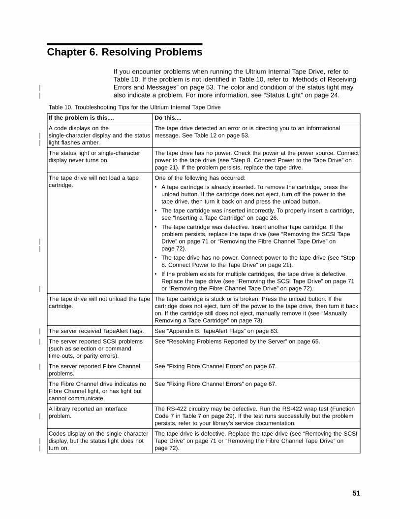
Chapter 6. Resolving Problems
If you encounter problems when running the Ultrium Internal Tape Drive, refer toTable 10. If the problem is not identified in Table 10, refer to “Methods of ReceivingErrors and Messages” on page 53. The color and condition of the status light mayalso indicate a problem. For more information, see “Status Light” on page 24.
Table 10. Troubleshooting Tips for the Ultrium Internal Tape Drive
If the problem is this.... Do this....
A code displays on thesingle-character display and the statuslight flashes amber.
The tape drive detected an error or is directing you to an informationalmessage. See Table 12 on page 53.
The status light or single-characterdisplay never turns on.
The tape drive has no power. Check the power at the power source. Connectpower to the tape drive (see “Step 8. Connect Power to the Tape Drive” onpage 21). If the problem persists, replace the tape drive.
The tape drive will not load a tapecartridge.
One of the following has occurred:
v A tape cartridge is already inserted. To remove the cartridge, press theunload button. If the cartridge does not eject, turn off the power to thetape drive, then turn it back on and press the unload button.
v The tape cartridge was inserted incorrectly. To properly insert a cartridge,see “Inserting a Tape Cartridge” on page 26.
v The tape cartridge was defective. Insert another tape cartridge. If theproblem persists, replace the tape drive (see “Removing the SCSI TapeDrive” on page 71 or “Removing the Fibre Channel Tape Drive” onpage 72).
v The tape drive has no power. Connect power to the tape drive (see “Step8. Connect Power to the Tape Drive” on page 21).
v If the problem exists for multiple cartridges, the tape drive is defective.Replace the tape drive (see “Removing the SCSI Tape Drive” on page 71or “Removing the Fibre Channel Tape Drive” on page 72).
The tape drive will not unload the tapecartridge.
The tape cartridge is stuck or is broken. Press the unload button. If thecartridge does not eject, turn off the power to the tape drive, then turn it backon. If the cartridge still does not eject, manually remove it (see “ManuallyRemoving a Tape Cartridge” on page 73).
The server received TapeAlert flags. See “Appendix B. TapeAlert Flags” on page 83.
The server reported SCSI problems(such as selection or commandtime-outs, or parity errors).
See “Resolving Problems Reported by the Server” on page 65.
The server reported Fibre Channelproblems.
See “Fixing Fibre Channel Errors” on page 67.
The Fibre Channel drive indicates noFibre Channel light, or has light butcannot communicate.
See “Fixing Fibre Channel Errors” on page 67.
A library reported an interfaceproblem.
The RS-422 circuitry may be defective. Run the RS-422 wrap test (FunctionCode 7 in Table 7 on page 29). If the test runs successfully but the problempersists, refer to your library’s service documentation.
Codes display on the single-characterdisplay, but the status light does notturn on.
The tape drive is defective. Replace the tape drive (see “Removing the SCSITape Drive” on page 71 or “Removing the Fibre Channel Tape Drive” onpage 72).
51
||
||
||
|
|
|
|
|
||

Table 10. Troubleshooting Tips for the Ultrium Internal Tape Drive (continued)
If the problem is this.... Do this....
The tape drive does not respond toserver commands.
Press and hold the unload button on the drive for 10 seconds to force a drivedump. The drive will save the dump and then reboot to allow communicationto the drive to occur. Do not cycle power, as this will erase the contents ofthe dump.
The status light flashes green. Typically, no action is required because a flashing green LED means normaloperation. However, the tape drive may have contained a cartridge when itwas powered-on. If so, the drive completes POST and slowly rewinds thetape (the process may take approximately 13 minutes). The light stopsblinking when the drive completes the recovery and is ready for a read orwrite operation. To eject the cartridge, press the unload button.
52 IBM Ultrium Internal Tape Drive
||||||
|||||||

Methods of Receiving Errors and MessagesUse Table 11 as a guide for identifying error codes and message codes reported bythe Ultrium Tape Drive, its enclosure (if applicable), or the server.
Note: The codes on the single-character display have different meanings,depending on whether they display during normal operations or while thedrive is in maintenance mode. Codes that occur during normal operationsare defined in Table 12. Codes that occur while in maintenance mode aredefined in Table 7 on page 29.
Table 11. Methods of Receiving Errors and Messages for the Ultrium Internal Tape Drive
If the error or message waspresented by....
Do this....
The enclosure’s display (if the tapedrive is enclosed in a library orautoloader)
Refer to the documentation for the enclosure.
The tape drive’s single-characterdisplay and the status light flashesyellow
See Table 12. To determine the meaning of status light activity, see “StatusLight” on page 24.
The tape drive’s single-characterdisplay and the status light is solidyellow
See Table 7 on page 29. To determine the meaning of status light activity,see “Status Light” on page 24.
SCSI log sense data (such asTapeAlert flags), SCSI drive sensedata, or Fibre Channel autosense dataat the server console
See “Appendix B. TapeAlert Flags” on page 83, Table 12, or “Using SenseData” on page 59.
Drive sense data sent to a library (ifthe tape drive is enclosed in a library)
Refer to your library’s documentation, then see Table 12.
The tape drive’s error log See Table 12 and “Viewing the Drive Error Log” on page 64.
Descriptions and Corrective Actions for Errors and MessagesTable 12 gives descriptions of the errors and messages that pertain to the UltriumTape Drive, and tells what to do when you receive them.
Attention: If the tape drive detects a permanent error and displays an error codeother than 0, it automatically performs a drive dump. If you force a drive dump, theexisting dump will be overwritten and data will be lost. After you force a drive dump,do not turn off the power to the tape drive or you may lose the dump data.
Table 12. Codes for Error Conditions and Informational Messages for the Ultrium Internal Tape Drive. Thesingle-character display clears if you power-off the drive.
Code Cause and Action
0 No error occurred and no action is required. This code displays:
v When power is cycled (turned off, then on) to the tape drive.
v When diagnostics have finished running and no error occurred.
Note: The single-character display is blank during normal operation of the tape drive.
Chapter 6. Resolving Problems 53
|
||||
||||

Table 12. Codes for Error Conditions and Informational Messages for the Ultrium Internal TapeDrive (continued). The single-character display clears if you power-off the drive.
Code Cause and Action
1 Cooling problem. The tape drive detected that the recommended operating temperature wasexceeded. Perform the following action:
1. If a fan is present in the enclosure, ensure that it is rotating and is quiet. If not, replace the fan(for instructions about replacing the fan, see your enclosure’s documentation or reverse thesteps in “Step 3. Install the Cooling Fan Assembly (Optional)” on page 11).
2. Remove any blockage that prevents air from flowing freely through the tape drive.
3. Ensure that the operating temperature and airflow is within the specified range (see “Chapter 2.Specifications” on page 7).
4. If the operating temperature is within the specified range and the problem persists, replace thetape drive.
The error code clears when you power-off the tape drive or place it in maintenance mode.
2 Power problem. The tape drive detected that the externally supplied power is either approachingthe specified voltage limits (the drive is still operating) or is outside the specified voltage limits (thedrive is not operating). Perform the following action:
1. Ensure that the power connector is properly seated.
2. Ensure that the proper dc voltages are being applied within the tolerances allowed (see“Chapter 2. Specifications” on page 7).
3. If the proper voltages are being applied but the problem persists, replace the tape drive.
The error code clears when you power-off the tape drive or place it in maintenance mode.
3 Firmware problem. The tape drive determined that a firmware error occurred. Perform the followingaction:
1. Collect a drive dump from one of the following:Note: Do not force a new dump; the tape drive has already created one.
v Server’s SCSI or Fibre Channel interface by using a device driver utility or system tool (forinstructions about reading a drive dump from tape, visit the Web athttp://www.ibm.com/storage/storagesmart/lto)
v Enclosure (refer to the procedures for reading a drive dump in your enclosure’sdocumentation)
v Ultrium Tape Drive (to read a drive dump, use Function Code 5 in Table 7 on page 29)
2. Power the tape drive off and on, then retry the operation that produced the error.
3. If the problem persists, download new firmware and retry the operation.
4. If the problem persists, send the drive dump that you collected in step 1 to your nearestCustomer Assistance Center (see “Getting Help” on page 90).
The error code clears when you power-off the tape drive or place it in maintenance mode.
54 IBM Ultrium Internal Tape Drive
|
|
|

Table 12. Codes for Error Conditions and Informational Messages for the Ultrium Internal TapeDrive (continued). The single-character display clears if you power-off the drive.
Code Cause and Action
4 Firmware or tape drive problem. The tape drive determined that a firmware or tape drive hardwarefailure occurred. Perform the following action:
1. Collect a drive dump from one of the following:Note: Do not force a new dump; one already exists.
v Server’s SCSI or Fibre Channel interface by using a device driver utility or system tool (forinstructions about reading a drive dump from tape, visit the Web athttp://www.ibm.com/storage/storagesmart/lto)
v Enclosure (refer to the procedures for reading a drive dump in your enclosure’sdocumentation)
v Ultrium Tape Drive (to read a drive dump, use Function Code 5 in Table 7 on page 29)
2. Power the tape drive off and on, then retry the operation that produced the error. The errorcode clears when you power-off the tape drive or place it in maintenance mode.
3. If the problem persists, download new firmware and retry the operation; if new firmware is notavailable, replace the tape drive.
5 Tape drive hardware problem. The drive determined that a tape path or read/write error occurred.To prevent damage to the drive or tape, the drive will not allow you to insert a cartridge if thecurrent cartridge was successfully ejected. If the problem persists, replace the tape drive. The errorcode may clear when you cycle power to the tape drive or place it in maintenance mode.
Chapter 6. Resolving Problems 55
|

Table 12. Codes for Error Conditions and Informational Messages for the Ultrium Internal TapeDrive (continued). The single-character display clears if you power-off the drive.
Code Cause and Action
6 Tape drive or media error. The drive determined that an error occurred, but it cannot isolate theerror to faulty hardware or to the tape cartridge. Perform the following action:
For Problems with Writing Data:
If the problem occurred while the drive was writing data to the tape, and if you know the volumeserial number (located on the cartridge label) of the tape cartridge loaded in the drive when theproblem occurred, retry the operation with a different cartridge:v If the operation succeeds, the original cartridge was defective. Copy data from the defective
cartridge and discard it.v If the operation fails and another drive is available, insert the cartridge into the other drive and
retry the operation.– If the operation fails, discard the defective cartridge.– If the operation succeeds, insert a scratch cartridge into the first drive and run the tape drive
diagnostics (see Function Code 1 in Table 7 on page 29).- If the diagnostics fail, replace the drive.- If the diagnostics succeed, the error was temporary.
v If the operation fails and another drive is not available, insert a scratch cartridge into the driveand run the tape drive diagnostics (see Function Code 1 in Table 7 on page 29).– If the diagnostics fail, replace the drive.– If the diagnostics succeed, discard the cartridge.
If the problem occurs with multiple tape cartridges or if you do not know the tape cartridge’svolume serial number, run the tape drive diagnostics (see Function Code 1 in Table 7 on page 29):v If the diagnostics fail, replace the tape drive.v If the diagnostics succeed, run the Test Head diagnostic (see Function Code H in Table 7 on
page 29).– If the Test Head diagnostic fails, replace the tape drive.– If the Test Head diagnostic succeeds, replace the cartridges that caused the problem.
The error code clears when you remove the tape cartridge or place the drive in maintenance mode.
For Problems with Reading Data:
If the problem occurred while the drive was reading data from the tape, and if you know the volumeserial number of the tape cartridge, perform one of the following procedures:v If another drive is available, insert the cartridge into the other drive and retry the operation:
– If the operation fails, discard the defective cartridge.– If the operation succeeds, insert a scratch cartridge into the first drive and run the tape drive
diagnostics (see Function Code 1 in Table 7 on page 29):- If the diagnostics fail, replace the drive.- If the diagnostics succeed, the error was temporary.
v If another drive is not available, insert a scratch cartridge into the drive and run the tape drivediagnostics (see Function Code 1 in Table 7 on page 29):– If the diagnostics fail, replace the drive.– If the diagnostics succeed, discard the cartridge.
If the problem occurs with multiple tape cartridges or if you do not know the tape cartridge’svolume serial number, run the tape drive diagnostics (see Function Code 1 in Table 7 on page 29):v If the diagnostics fail, replace the tape drive.v If the diagnostics succeed, run the Test Head diagnostic (see Function Code H in Table 7 on
page 29).– If the Test Head diagnostic fails, replace the tape drive.– If the Test Head diagnostic succeeds, replace the cartridges that caused the problem.
The error code clears when you remove the tape cartridge or place the drive in maintenance mode.
56 IBM Ultrium Internal Tape Drive
|||
||||||||
|||||||
|
||||||||
||||||

Table 12. Codes for Error Conditions and Informational Messages for the Ultrium Internal TapeDrive (continued). The single-character display clears if you power-off the drive.
Code Cause and Action
7 A high probability of media error. The tape drive determined that an error occurred because of afaulty tape cartridge. Try another tape cartridge. If the problem occurs with multiple tape cartridges,see “Resolving Media-Related Problems” on page 69.
The error code clears when you remove the tape cartridge or place the drive in maintenance mode.
8 For SCSI drive:
Tape drive or SCSI bus failure. The tape drive determined that a failure occurred in the tape drive’shardware or in the SCSI bus. See “Fixing SCSI Bus Errors” on page 65. The error code clears 10seconds after the drive detected the error or when you place the drive in maintenance mode.
For Fibre Channel drive:
Tape drive or Fibre Channel failure. The tape drive determined that a failure occurred in the tapedrive’s hardware or in the Fibre Channel. It detects light through the fiber cable but cannot performdata communication properly. The length of the cable between the devices may exceed 500 m(1640 ft). See “Fixing Fibre Channel Errors” on page 67. The error code clears when the drivedetects light and can communicate, or when you place the drive in maintenance mode.
9 Tape drive or RS-422 error. The tape drive determined that a failure occurred in the tape drivehardware or in the RS-422 connection. Run the RS-422 wrap test (see Function Code 7 in Table 7on page 29):
v If the diagnostic fails, replace the tape drive.
v If the diagnostic runs successfully, the problem is with the enclosure or the cable to theenclosure. Refer to your enclosure’s documentation.
The error code clears 10 seconds after the drive detected the error or when you place the drive inmaintenance mode.
o, c, b, or h No error or message assigned. There may be a problem with the single-character display. Turn thepower off, then on and determine whether all segments on the single-character display are lit. If so,you may have a down-level version of both your enclosure’s firmware and documentation (thedocumentation may not describe all of the available error codes). Refer to the latest version of thefirmware or documentation.
A Tape drive hardware problem. The tape drive determined that a problem occurred which degradedthe operation of the tape drive, but it did not restrict continued use. If the problem persists, replacethe tape drive. The drive is usable, though the single-character display continues to indicate anerror and the status light flashes amber.
The error code may clear when you cycle power to the tape drive or place it in maintenance mode.
B No error or message is assigned. See error code 8 in this table.
C The tape drive needs to be cleaned. Clean the tape drive. See “Cleaning the Drive Head” onpage 27.
The error code clears when you clean the tape drive or place it in maintenance mode.
d Fibre Channel AL_PA conflict. More than one device has the same address. Each device musthave its own unique AL_PA address. See “Step 6. Set the Arbitrated Loop Physical Address (FibreChannel Drive Only)” on page 15.
D No error or message assigned. See error code 0 in this table.
Chapter 6. Resolving Problems 57
||
|||
|||

Table 12. Codes for Error Conditions and Informational Messages for the Ultrium Internal TapeDrive (continued). The single-character display clears if you power-off the drive.
Code Cause and Action
E Informational message. The tape drive’s Fibre Channel port has been placed offline by anotherdevice or by an operator. This code is set when the Offline command is received from anotherdevice on the Fibre Channel interface. Determine why the device at the other end of the FibreChannel (the server, switch, or other device) placed the drive offline.
The drive is placed online when it receives the Online command from the Fibre Channel interface.
After a reset, the drive comes online.
F The tape drive determined that no light is being received over the Fibre Channel. See “Fixing FibreChannel Errors” on page 67.
The error code clears when the drive detects light or when you place the drive in maintenancemode.
58 IBM Ultrium Internal Tape Drive
|||||
|
|
|||
||

Using Sense DataWhen a tape drive encounters an error, it makes sense data available. You can useIBM device drivers to examine the sense data and determine errors. Instructions fordownloading, installing, and properly configuring the IBM device drivers areavailable in the IBM Ultrium Device Drivers Installation and User’s Guide. The IBMdevice drivers may conflict with some commercial software applications unlessproperly configured. To avoid conflicts on Windows® operating systems, refer toyour device driver’s procedures for setting the driver to manual startup mode. Forapplications that use Open Systems device drivers that are provided by IBM (forexample, AIX, Linux, Sun Solaris, HP-UX, Windows/NT, and Windows 2000), theIBM Ultrium Device Drivers Installation and User’s Guide contains information abouthow to obtain sense data after an error has occurred.
If your application uses other device drivers, see the appropriate documentation forthose drivers to obtain the sense data.
Raw sense data (as returned from the Ultrium Tape Drive) is documented in theIBM Ultrium Internal Tape Drive Models T200 and T200F and IBM 3580 UltriumTape Drive SCSI Reference.
In addition to device drivers, other methods exist for obtaining sense data and errorinformation. The sections that follow describe alternative ways for gathering suchinformation from the IBM AS/400, Eserver iSeries, RS/6000, and Eserver
pSeries servers.
Obtaining Error Information from the AS/400 or Eserver iSerieswith RISC ProcessorFor OS/400, sense data is provided by the System Service Tools application. Toobtain error information from the AS/400 or Eserver iSeries by using the tool:
1. On the command entry line of the AS/400 Main Menu, type STRSST (StartSystem Service Tools) and press Enter.
2. Select Start a service tool.
3. Select Product activity log.
4. Select Analyze log.
5. Specify the time period for searching the error log, then select the Magneticmedia option.
6. On the Select Analysis Report Options menu, specify a device type of 3580 andpress Enter. Leave all other options at their default values.
7. Use the Display Report option to display the desired error log entry. Figure 17on page 60 shows a sample error log for the Ultrium Tape Drive.
Chapter 6. Resolving Problems 59
||||
|||
||||
||
||
|
|
|
||
||
|||

8. Press F4 to view the sense data (see the example in Figure 18).
Obtaining Error Information from the RS/6000 or Eserver
pSeriesThe AIX® Tape and Media Changer Device Driver for the IBM RS/6000 or IBMEserver pSeries provides logging to the system error log for a variety of errors.You can view the error log by issuing the AIX errpt command. Figure 19 onpage 61 displays a sample drive error log; Figure 20 on page 62 displays a sampleSCSI bus error log.
To view the error log:
1. At the AIX command line, type errpt -a |pg to display a detailed report.
2. Press Enter to scroll through the error log.
3. Type q to quit the error log at any time.
Display Detail Report for Resource
Serial ResourceName Type Model Number NameTAP07 3580 001 00-00000 TAP07
Log ID . . . . . . . . . : 00452B54 Sequence . . . . . . : 4732468Date . . . . . . . . . . : 02/14/01 Time . . . . . . . . : 09:50:21Reference code . . . . . : 9210 Secondary code . . . : 00000000Table ID . . . . . . . . : 63A00001 IPL source/state . . : B/3
Class . . . . . . . . . . : PermanentSystem Ref Code . . . . . : 63A09210Illegal or unsupported tape unit response
Press Enter to continue.
F3=Exit F4=Additional Information F6=Hexadecimal reportF9=Address Information F10=Previous detail report F12=Cancel
Figure 17. Example of an Error Log from the AS/400 or IBM Eserver iSeries
Display Additional Information for Resource
Serial ResourceName Type Model Number NameTAP07 3580 001 00-00000 TAP07
SENSE DATA FOLLOWS. . . . . :DATA OFFSET 0 1 2 3 4 5 6 7 8 9 A B C D E F00000000 70000500 0000001C 00000000 240000C000000010 00020000 00000000 00000000 0000000000000020 058B0000
Figure 18. Example of Sense Data from the AS/400 or IBM Eserver iSeries
60 IBM Ultrium Internal Tape Drive
||||||||||||||||||||||
|||
||||||||||||||
|||
|

Example of a Drive Error Log:
In the SENSE DATA area of Figure 19, entries in bold are defined as follows:
Hexadecimal Code Description
01 SCSI Command
0000, 0200, 0000 Command parameters
70 Byte 0 of SCSI sense data
03 Sense key
5200 ASC/ASCQ (Additional Sense Code/Additional Sense CodeQualifier)
20B0 FSC (Fault Symptom Code)
058A Relative LPOS
02 SCSI ID
LABEL: TAPE_ERR1IDENTIFIER: 4865FA9B
Date/Time: Wed Oct 11 11:39:43Sequence Number: 25264Machine ID: 000D090D4C00Node ID: tsmClass: HType: PERMResource Name: rmt2Resource Class: tapeResource Type: LTOLocation: 40-60-00-2,0VPD:
Manufacturer................IBMMachine Type and Model......ULT3580-TD1Serial Number...............1300015078Device Specific.(FW)........0B70 (Firmware Level)
DescriptionTAPE OPERATION ERROR
Probable CausesTAPE
User CausesMEDIA DEFECTIVEDIRTY READ/WRITE HEAD
Recommended ActionsFOR REMOVABLE MEDIA, CHANGE MEDIA AND RETRYPERFORM PROBLEM DETERMINATION PROCEDURES
Detail DataSENSE DATA0602 0000 0100 0000 0200 0000 0000 0000 0000 0000 7000 0300 0000 001C 0000 00005200 0700 20B0 0000 0000 0000 0000 0000 0000 0000 058A 0200 0000 0000 0000 00000000 0000 0000 0000 0000 0000 0000 0000 0000 0000 0000 0000 0000 0000 0000 00000000 0000 0000 0000 0000 0000 0000 0000 0000 0000 0000 0000 0000 0000 0000 00000000 0000 0000 0000 0000 0000 0000 0000 0000 0000 0000 0000 0000 0000
Figure 19. Example of an AIX ERRPT Drive Error Log
Chapter 6. Resolving Problems 61
|

Example of a SCSI Bus Error:
LABEL: SCSI_ERR10IDENTIFIER: 0BA49C99
Date/Time: Wed Oct 18 09:55:32Sequence Number: 16140Machine Id: 00003ABF4C00Node Id: ofgtsmClass: HType: TEMPResource Name: scsi3Resource Class: adapterResource Type: sym896Location: 40-59VPD:
Product Specific.( ).......DUAL CHANNEL PCI TO ULTRA2 SCSIADAPTER
Part Number.................03N3606EC Level....................F71335Manufacture ID..............A16592Serial Number...............0749
DescriptionSCSI BUS ERROR
Probable CausesCABLECABLE TERMINATORDEVICEADAPTER
Failure CausesCABLE LOOSE OR DEFECTIVEDEVICEADAPTER
Recommended ActionsPERFORM PROBLEM DETERMINATION PROCEDURESCHECK CABLE AND ITS CONNECTIONS
Detail DataSENSE DATA0001 0017 0000 0000 0000 0091 0000 0000 0000 0000 0000 0000 0000 0000 0000 00000000 0000 0000 4304 0000 0000 0000 0000 2000 0003 0203 6760 9808 0000 F7FB E1B80000 0015 000B 0210 0678 C800 0000 8200 8277 1B20 00A2 ED00 0000 0002 FFFF FFFF00FF 0000 111F F000 F3DF F110
Figure 20. Example of an Error that Suggests a SCSI Bus Problem
62 IBM Ultrium Internal Tape Drive

Obtaining a Drive DumpYou can obtain a drive dump by selecting a function code on the Ultrium InternalTape Drive or by using a device driver utility (or a system tool) on the server. Thesections that follow describe each method.
Using the Drive to Obtain a DumpTo obtain a drive dump directly from the Ultrium Internal Tape Drive:
1. Make sure that no cartridge is in the drive.
2. Within a 1-second interval, press the unload button three times. The status lightbecomes solid amber, which means that the drive is in maintenance mode.
3. Press the unload button once per second until 5 appears in the single-characterdisplay.
4. To select the function, press and hold the unload button for 3 seconds. After yourelease the button, C flashes. Within 60 seconds, insert a scratch data cartridgethat is not write-protected. After you insert the cartridge, 5 flashes and the drivewrites the dump data to the scratch tape. When the function is complete, thedrive rewinds and unloads the tape.
5. Insert the tape into a drive.
6. From the server, issue the SCSI READ command to read the dump from thetape to a file or electronic image (you may need to issue the command severaltimes to read the complete dump).
7. To determine where to send the file for analysis, contact your nearest CustomerAssistance Center (see “Getting Help” on page 90).
Using a Device Driver Utility to Obtain a DumpTo obtain a drive dump by using a device driver utility, determine whether yourserver is installed with a utility that can read files from the server’s memory. Openthe tool and select the options to force the dump, read it, and write it to a file foranalysis.
There are many device driver utilities and system tools that read data from a tapecartridge. For AIX-attached drives, the dd command or tapeutil (the IBM devicedriver utility) can be used. For Windows NT and Windows 2000, ntutil (another IBMdevice driver) can be used, but NT Backup cannot be used.
Note: After starting ntutil and opening the tape drive, select option 47: restoredata.
For more information about capturing and reading drive dumps, visit the web athttp://www.storage.ibm.com/techsup/tapetech/tapedumps.htm.
For information about using IBM and non-IBM device driver utilities with WindowsNT, Windows 2000, AIX, Sun Solaris, and HP-UX, see the IBM Ultrium DeviceDrivers Installation and User’s Guide. To learn about other facilities that read datafrom a tape, refer to your operating system’s documentation.
To determine where to send a file that contains a drive dump to be analyzed,contact your nearest Customer Assistance Center (see “Getting Help” on page 90).
Chapter 6. Resolving Problems 63
|
|||
||
|
||
||
|||||
|
|||
||
|||||
||||
||
||
||||
||

Viewing the Drive Error LogThe Ultrium Tape Drive keeps an error log that you can use to identify and correcterrors. The log contains the 10 most recent error codes, which appear (one at atime) on the single-character display.
To view the drive error log:
1. Make sure that no cartridge is in the drive.
2. Within a 1-second interval press the unload button three times. The status lightbecomes solid amber, which means that the drive is in maintenance mode.
3. Press the unload button once per second until 9 appears in the single-characterdisplay.
4. Press and hold the unload button for 3 seconds to view the most recent errorcode.
5. Refer to Table 12 on page 53 to determine the meaning of the code and theaction to take.
6. Press the unload button to view the next error code. (The codes are ordered;the most recent is presented first and the oldest (tenth) is presented last.)
7. Continue to press the unload button until the 10 error codes have beendisplayed. After you display the tenth error code, the drive automatically exitsmaintenance mode.
To redisplay the error codes, repeat steps 1 through 7.
64 IBM Ultrium Internal Tape Drive
|

Resolving Problems Reported by the ServerThe procedure for fixing SCSI bus or Fibre Channel errors varies, depending onwhether the error is consistent or intermittent, and whether your configurationcontains single or multiple Ultrium Tape Drives. The sections that follow describehow to fix each type of error.
Fixing SCSI Bus Errors
Note: If you are using a Storage Area Network (SAN) Data Gateway to convert adrive with a SCSI interface to a Fibre Channel interface, ensure that theproblem is occurring between the SAN Data Gateway and the drive byrunning the SCSI wrap test on the drive and running the SCSI loopback teston the SAN Data Gateway. (To run the SCSI wrap test, see Function Code 6in Table 7 on page 29; to run the SCSI loopback test, refer to the sectionabout that test in the IBM Storage Area Network Gateway Module Setup,Operator, and Service Guide.)
Fixing a Consistent Error with a Single Drive on a SCSI Bus1. Ensure that the power is on to the Ultrium Tape Drive.
2. Ensure that the tape drive’s SCSI address is the same as the SCSI addressassigned by the server.
3. Run the SCSI wrap test (see Function Code 6 in Table 7 on page 29).
v If the test runs successfully, replace the SCSI terminator first, then the SCSIcable and the interposer (if installed). Repeat the operation that caused theerror. If you replaced the SCSI terminator or SCSI cable and the problempersists, the fault is with the server’s hardware or software. To isolate thecause of the failure, refer to the server’s service documentation.
v If the test fails, replace the tape drive (see “Removing the SCSI Tape Drive”on page 71).
Fixing a Consistent Error with Multiple Drives on a SCSI BusWhen a consistent error occurs in a configuration that has multiple tape drives onthe SCSI bus, you must determine if the problem exists with more than one tapedrive. If the problem is with all of the devices on the SCSI bus, the bus is stuck in aSCSI phase and cannot change to another phase or the SCSI cable from the serverto the first device is defective.
1. Ensure that the SCSI cable from the server to the first device is connected.
2. Disconnect all but the first tape drive on the SCSI bus. Move the terminator tothe first SCSI device.
3. Run a device driver utility (such as IBM’s ntutil or tapeutil) to determine whetherthe error will occur.
v If the error occurs, run the SCSI wrap test on the first tape drive (seeFunction Code 6 in Table 7 on page 29).
– If the test runs successfully, replace the SCSI terminator first, then theSCSI cable and the interposer (if installed) to the first tape drive. Repeatthe operation that caused the error. If you replaced the SCSI terminator orSCSI cable and the problem persists, the fault is with the server’shardware or software. To isolate the cause of the failure, refer to theserver’s service documentation.
– If the test fails, replace the tape drive (see “Removing the SCSI TapeDrive” on page 71).
Chapter 6. Resolving Problems 65
|
||||||||
|
||
||
|
|
|

v If the error does not occur, connect one tape drive at a time back to the busand repeat step 3 for each tape drive until you can identify which drive isdefective.
Note: Ensure that the SCSI terminator is always on the last tape drive on theSCSI bus.
4. Determine if the problem is with only one tape drive or with two or more tapedrives.
v If the problem is with only one tape drive, run the SCSI wrap test on that tapedrive (see Function Code 6 in Table 7 on page 29).
– If the test runs successfully, replace the SCSI terminator first, then theSCSI cable to that tape drive and interposer (if installed).
– If the test fails, replace the tape drive (see “Removing the SCSI TapeDrive” on page 71).
v If the problem is with two or more tape drives, locate the first tape drive thathas the error and replace the SCSI cable that connects the tape drive andthe interposer (if installed).
Fixing an Intermittent Error with a Single Drive on a SCSI Bus1. Replace the SCSI terminator on the tape drive.
2. Run the operation that caused the error. If the problem persists, the problemmay be with the cable.
3. Isolate which cable is causing the problem by replacing one cable at a time andrunning the operation that caused the error after each replacement. If theproblem persists after all cables have been replaced, the problem may be withthe Ultrium Tape Drive.
4. Replace the tape drive (see “Removing the SCSI Tape Drive” on page 71). If theproblem persists, the problem is with your server. Consult your server’sdocumentation.
Fixing an Intermittent Error with Multiples Drives on a SCSI BusRefer to the server’s error logs to determine which tape drive is the source of theproblem:
v If only one tape drive is reporting a SCSI failure, replace that tape drive (see“Removing the SCSI Tape Drive” on page 71).
v If multiple tape drives are reporting SCSI failures, the problem may be with theterminator or the SCSI cables:
– Replace the terminator and run the operation that caused the error. If theproblem persists, the problem may be with the cables.
– Isolate which cable is causing the problem by replacing one cable at a timeand run the operation that caused the error after each replacement.
66 IBM Ultrium Internal Tape Drive
|
|

Fixing Fibre Channel Errors
Starting Problem DeterminationBefore starting the problem determination, perform the following steps:
1. Determine the type of Fibre Channel topology that you are using (see“Supported Topologies” on page 4).
2. Using this guide or the service guides of associated switch, hub, or fiberproducts, try to determine where the problem exists (whether in the drive, cable,or the device to which the drive and cable attach).
3. Ensure that the configuration and software levels are supported (see “FibreChannel Attachment” on page 3).
4. If you are connected to a Fibre Channel Storage Area Network (SAN) by usinga SAN Data Gateway, use the IBM Storage Area Network Gateway ModuleSetup, Operator, and Service Guide to determine whether the problem isoccurring between the drive and the SAN Data Gateway. If you are using aSCSI drive and are having SCSI problems, see “Fixing SCSI Bus Errors” onpage 65.
5. Ensure that the Fibre Channel cables are installed correctly. Refer to theappropriate steps in “Chapter 3. Installing the Tape Drive” on page 9.
6. Go to one of the following procedures:
v “Fixing a Consistent Error with a Single Drive on a Fibre Channel Loop”
v “Fixing a Consistent Error with Multiple Drives on a Fibre Channel Loop” onpage 68
v “Fixing Intermittent Fibre Channel Errors” on page 68
Fixing a Consistent Error with a Single Drive on a Fibre ChannelLoop1. Ensure that the tape drive is powered on.
2. Verify that the tape drive’s serial number is the same as the drive serial numberthat the server program is using.
3. Ensure that the drive’s Fibre Channel AL_PA is set correctly, that it is on theloop, and that it is not being used by another device (see “Step 6. Set theArbitrated Loop Physical Address (Fibre Channel Drive Only)” on page 15). Thetape drive must be able to detect light and communicate with the server.
4. Run the Fibre Channel wrap test at the drive’s Fibre Channel connector (seeFunction Code 6 in Table 7 on page 29).
v If the test fails, replace the tape drive.
v If the test is successful, go to step 5.
5. Run the Fibre Channel wrap test at the end of the fiber cable (see FunctionCode 6 in Table 7 on page 29).
v If the test fails, replace the fiber cable.
v If the test is successful, go to step 6.
6. Check the Fibre Channel cable connection at the server.
7. Using a device driver utility such as ntutil or tapeutil, verify that the drive isproperly configured and available at the server.
8. If the problem persists, the fault may be with the server’s hardware or software.Refer to your server’s service manual.
9. When the problem is corrected (or determined to be a server problem), restoreall of the fiber cables to their correct position.
Chapter 6. Resolving Problems 67
|
||
||
|||
||
||||||
||
|
|
||
|
|||
||
||||
||
|
|
||
|
|
|
||
||
||

Fixing a Consistent Error with Multiple Drives on a Fibre ChannelLoopUse the following procedure to determine if all of the drives on the Fibre Channelhave the problem:
1. Use a device driver utility (such as ntutil or tapeutil) to verify that the drive isavailable and properly configured at the server.
2. Determine the type of Fibre Channel topology that you are using (see“Supported Topologies” on page 4).
3. Using this guide or the service guides of associated switch, hub, or fiberproducts, try to isolate which part of the Fibre Channel Storage Area Network(SAN) is experiencing problems.
4. Perform one of the following:
v If the problem exists on a small number of drives, go to “Fixing a ConsistentError with a Single Drive on a Fibre Channel Loop” on page 67.
v If the problem exists with a large number of drives, perform the followingsteps:
a. Disconnect all except one failing drive on the Fibre Channel.
b. Run the Fibre Channel wrap test to determine if a failure occurs on thatdrive (see Function Code 6 in Table 7 on page 29). If it does, perform theprocedure in “Fixing a Consistent Error with a Single Drive on a FibreChannel Loop” on page 67.
c. Continue to connect one drive at a time to the Fibre Channel loop.
5. When the problem is corrected, restore all of the Fibre Channel cables to theircorrect position.
Fixing Intermittent Fibre Channel Errors1. Determine the type of Fibre Channel topology that you are using (see
“Supported Topologies” on page 4).
2. Ensure that the configuration and software levels are supported (see “FibreChannel Attachment” on page 3).
3. Check that each Fibre Channel cable does not exceed 500 m (1640 ft).
4. Ensure that all Fibre Channel cables are installed correctly. Refer to theappropriate steps in “Chapter 3. Installing the Tape Drive” on page 9.
5. Using this guide or the service guides of associated switch, hub, or fiberproducts, determine that a problem exists between the drive, drive cable, andthe device to which they attach. Try to isolate which part of the Storage AreaNetwork (SAN) is experiencing problems.
6. Using this guide or the service guides of associated switch, hub, or fiberproducts, verify that the SAN configurations are correct (such as switch zoningfor drive sharing).
7. Obtain all errors reported by the drive to the server (see “Using Sense Data” onpage 59), then contact your nearest Customer Assistance Center for erroranalysis (see “Getting Help” on page 90).
68 IBM Ultrium Internal Tape Drive
||||
||
||
|||
|
||
||
|
||||
|
||
|||
||
|
||
||||
|||
|||

Resolving Media-Related ProblemsTo resolve problems that are related to media, the Ultrium Tape Drive’s firmwareincludes:
v Test Cartridge & Media diagnostic that verifies whether a suspect cartridge andits magnetic tape are acceptable for use.
v Statistical Analysis and Reporting System (SARS) to assist in isolating failuresbetween media and hardware. To determine the cause of failure, SARS uses thecartridge performance history that is saved in the cartridge memory (CM) and thedrive performance history that is kept in the drive’s flash erasable programmableread-only memory (EPROM). Any failures that SARS detects are reported asTapeAlert flags on the server (see “Appendix B. TapeAlert Flags” on page 83).
Attention: If you insert the IBM LTO Ultrium Data Cartridge into anothermanufacturer’s tape drive, the SARS data in the cartridge memory may becomelost or invalid.
If you encounter a media-related problem, use the following procedure:
Attention: When you run the Test Cartridge & Media diagnostic, data on thesuspect tape is overwritten. Use only a scratch data cartridge to run the test.
1. If possible, run the tape cartridge in a different tape drive. If the operation in theother tape drive fails and 6 or 7 displays, replace the media. If the operationsucceeds, run the Test Cartridge & Media diagnostic (see Function Code E inTable 7 on page 29).
2. If the Test Cartridge & Media diagnostic fails, replace the media. If it runssuccessfully, clean the tape drive and run the tape drive diagnostics (see“Cleaning the Drive Head” on page 27 and Function Code 1 in Table 7 onpage 29).
3. If the tape drive diagnostics fail, replace the tape drive. If the tape drivediagnostics run successfully, perform the operation that produced the initialmedia error.
Chapter 6. Resolving Problems 69
|
|
||

70 IBM Ultrium Internal Tape Drive
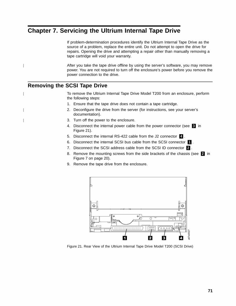
Chapter 7. Servicing the Ultrium Internal Tape Drive
If problem-determination procedures identify the Ultrium Internal Tape Drive as thesource of a problem, replace the entire unit. Do not attempt to open the drive forrepairs. Opening the drive and attempting a repair other than manually removing atape cartridge will void your warranty.
After you take the tape drive offline by using the server’s software, you may removepower. You are not required to turn off the enclosure’s power before you remove thepower connection to the drive.
Removing the SCSI Tape DriveTo remove the Ultrium Internal Tape Drive Model T200 from an enclosure, performthe following steps:
1. Ensure that the tape drive does not contain a tape cartridge.
2. Deconfigure the drive from the server (for instructions, see your server’sdocumentation).
3. Turn off the power to the enclosure.
4. Disconnect the internal power cable from the power connector (see �3� inFigure 21).
5. Disconnect the internal RS-422 cable from the J2 connector �4�.
6. Disconnect the internal SCSI bus cable from the SCSI connector �1�.
7. Disconnect the SCSI address cable from the SCSI ID connector �2�.
8. Remove the mounting screws from the side brackets of the chassis (see �2� inFigure 7 on page 20).
9. Remove the tape drive from the enclosure.
a6
7e
00
27
1 2 3 4
Figure 21. Rear View of the Ultrium Internal Tape Drive Model T200 (SCSI Drive)
71
|
|
|
|

Removing the Fibre Channel Tape DriveTo remove the Ultrium Internal Tape Drive Model T200F from an enclosure, performthe following steps:
1. Ensure that the tape drive does not contain a tape cartridge.
2. Deconfigure the drive from the server (for instructions, see your server’sdocumentation).
3. Turn off the power to the enclosure.
4. Disconnect the internal power cable from the power connector (see �1� inFigure 22).
5. Disconnect the internal RS-422 cable from the J2 connector �4�.
6. Disconnect the internal fiber cable from the Fibre Channel connector �3�.
7. Disconnect the fiber address cable from the LID/status connector �2�.
8. Remove the mounting screws from the side brackets of the chassis (see �2� inFigure 7 on page 20).
9. Remove the tape drive from the enclosure.
a6
7e
00
45
1 2 3 4
Figure 22. Rear View of the Ultrium Internal Tape Drive Model T200F (Fibre Channel Drive)
72 IBM Ultrium Internal Tape Drive
|
|
|

Manually Removing a Tape CartridgeIf a tape cartridge fails to eject from the Ultrium Internal Tape Drive, you canmanually remove the cartridge. The following tools are required for the procedure:
v 2.5-mm allen wrench
v #3 Phillips screwdriver
v Small-blade screwdriver or potentiometer-setting tool
v Flashlight (optional)
Attention: Before performing this procedure, note the following:
v This procedure may damage the tape cartridge. If you use this procedure, you mustreplace the stuck tape cartridge after removing it and copying its data to another cartridge.If you choose to return the drive and the stuck tape cartridge to your reseller formaintenance, the tape cartridge will be scrapped.
v The use of a power screwdriver to perform this procedure can destroy the tape.
v Never touch the head or electronic components within the drive. Touching may causecontamination or damage by electrostatic discharge.
Chapter 7. Servicing 73
||
|
|
|
|
||
|
|
||||
|
||
||

To manually remove a tape cartridge, perform the following steps:
1. Place the drive so that the front faces you, then tilt it on its left side (seeFigure 23).
2. Locate the access hole at the bottom of the unit (see �1� in Figure 23).
3. Insert a 2.5-mm allen wrench into the access hole and position the wrench sothat it is seated in the screw of the supply reel motor (the screw is not visible).
4. Push open the door of the tape load compartment and locate the flag �2� onthe cartridge’s takeup reel.
Attention: In the following step, rotate the allen wrench clockwise, notcounterclockwise. A counterclockwise motion may damage the tape.
5. To determine whether the tape is broken, watch the flag �2� on the cartridge’stakeup reel while you rotate the allen wrench �1� clockwise (do not let thewrench move counterclockwise):v If the takeup reel turns when you rotate the supply reel motor screw
clockwise with the allen wrench, the tape is not broken. Go to step 6 onpage 75.
v If the takeup reel does not turn when you rotate the supply reel motor screwclockwise with the allen wrench and if supply reel motor screw rotates freely,the tape is broken. Insert a small-blade screwdriver or potentiometer-settingtool into the access hole for the loader motor gear �3�. Rotate thescrewdriver counterclockwise. You may have to rotate for a lengthy period:– If the cartridge moves up, the tape is completely in the cartridge.
Continue rotating the screwdriver until the cartridge ejects. Remove thecartridge.
– If you feel resistance and the cartridge does not move up, the tape isbroken or the leader block is not in the home position. Go to “Fixing anInternal Jam” on page 76.
1
2
3
a67e0051
3
Figure 23. Determining Whether the Tape is Broken
74 IBM Ultrium Internal Tape Drive
|
||
|
||
|||
||
|||||||||||||||||
|

6. Continue to rotate the allen wrench until you feel resistance. The tape hasbeen rewound as far as it can go without unthreading.
Note: The number of required rotations depends on where the beginning ofthe tape is on the cartridge’s takeup reel. You may have to rotate theallen wrench for a lengthy period.
7. With the allen wrench still inserted into the bottom access hole, insert asmall-blade screwdriver or potentiometer-setting tool into the access hole forthe loader motor gear �3�.
8. While keeping torque on the supply reel motor screw and rotating the allenwrench �1� clockwise, rotate the loader motor gear with the small-bladescrewdriver �3� counterclockwise (see arrow). As you rotate the screwdriver,the allen wrench moves slightly.
9. With the small-blade screwdriver, continue to rotate the loader motor gear inthe unload direction (counterclockwise):
v If you feel no resistance to the allen wrench and the cartridge slowly movesup and out of the tape load compartment, the procedure was successful. Goto step 10.
v If you feel resistance to the allen wrench and the cartridge does not move,the loader mechanism is jammed. Go to “Fixing an Internal Jam” onpage 76.
10. Remove the tape cartridge.
After you remove the stuck tape cartridge, copy the data on the tape to anothertape. Then, if appropriate, return the stuck tape cartridge in its original packaging orin the packaging from its replacement to your reseller. If the leader pin detachedfrom the tape in the cartridge, go to “Reattaching a Leader Pin” on page 44.
Chapter 7. Servicing 75
||
|||
|||
||||
||
|||
|||
|
||||

Fixing an Internal JamTo fix a jammed loader mechanism and rewind the tape in a tape cartridge, performthe following procedure.
Attention: If you use a power screwdriver to perform this procedure itcould destroy the tape.
1. If the drive is mounted in an enclosure, perform the procedure to remove it(see “Removing the SCSI Tape Drive” on page 71 or “Removing the FibreChannel Tape Drive” on page 72).
2. Place the drive on a nonslip surface.
3. Remove the cover of the drive by performing the following steps:
a. Remove the three screws and washers (see �1� in Figure 24) that securethe bezel �2�. Remove the bezel.
b. Remove the four cover-mounting screws and washers �3�.
c. Remove the cover by lifting it up. Set the cover aside.
Attention: Never touch the head or electronic components within thetape drive. Touching may cause contamination or damage by electrostaticdischarge.
A67E
0023
3
2
1
1
3
Figure 24. Removing the Top Cover of the Drive
76 IBM Ultrium Internal Tape Drive
|

4. Place the tape drive so that the front faces you, then tilt it on its left side (seeFigure 25).
5. At the bottom of the drive, locate the access hole (�1� in Figure 25).
Attention: In the next step, do not let the leader-pin block touch the head.Damage may result to the head.
6. Insert a 2.5-mm allen wrench into the access hole and position the wrench sothat it is seated in the screw of the supply reel motor (the screw is not visible).
7. With clean needle-nose pliers, grasp the end of the leader pin and pull it out ofthe cartridge so that you can grip it with your fingers (see �2� in Figure 25).
8. While keeping the tape taut with your fingers, rotate the allen wrench clockwise�1� to wind the excess tape into the cartridge. Guide the leader pin toward thecartridge and drop it inside the cartridge door. Ensure that no tape is leftoutside of the cartridge. Remove the allen wrench.
Note: Do not attempt to seat the leader pin into the cartridge’s clips; this willinterfere with the motion of the leader-pin block.
a6
7s0
06
1
2
1
Figure 25. Rewinding the Leader Pin into the Tape Cartridge
Chapter 7. Servicing 77
|
|
|

9. Manually rotate the loader motor gear (see �1� in Figure 26) in the unloaddirection (counterclockwise) until the leader-pin block �2� reaches the lastroller �3�.
10. To prevent the leader-pin block from jamming, press down on the linkage ofthe leader-pin block �4� to force the hinged section of the block upward.
11. While manually rotating the loader motor gear in the unload direction, guide theend of the leader-pin block �5� into the white block guide (home position) �6�.The leader-pin block will pivot so that it clears the cartridge shell.
12. Continue to rotate the loader motor gear counterclockwise until you feelresistance and the cartridge rises and ejects. The leader-pin block must be inhome position �6� to allow the cartridge to rise and eject.
1
2
a67s0125
6
4
5
3
4
6
5
Figure 26. Guiding the Leader Pin into the Tape Cartridge
78 IBM Ultrium Internal Tape Drive
||
13. Remove the tape cartridge. If the leader pin is not seated correctly in thecartridge, see “Reattaching a Leader Pin” on page 44.
14. Copy the data on the stuck tape cartridge to another cartridge. If appropriate,return the stuck tape cartridge for analysis in its original packaging or in thepackaging from its replacement.
If you need help with this procedure, contact your nearest Customer AssistanceCenter (see “Getting Help” on page 90).
To reassemble the tape drive, reverse the preceding steps.
Chapter 7. Servicing 79
|||

80 IBM Ultrium Internal Tape Drive

Appendix A. Tools and Supplies
Table 13 lists the tools and supplies that you can use with the Ultrium Internal TapeDrive. To order tools and supplies, visit the web athttp://www.ibm.com/storage/storagesmart/lto, or contact your preferred reselleror distributor.
Note: The SCSI, Fibre Channel, and RS-422 wrap plugs are not provided with thetape drive.
Table 13. Tools and Supplies for the Ultrium Internal Tape Drive
IBM Part Number Product Description
08L9129 Leader pin reattachment kit
- - 2.5-mm allen wrench (procure locally)
08L9120 IBM LTO Ultrium Data Cartridge
08L9124 IBM LTO Ultrium Cleaning Cartridge
19P0481 Single port LVD wrap plug
08L9459 Single port Fibre Channel wrap plug (formerly part number34L2629)
19P0519 RS-422 wrap plug
19P0242 Fibre Channel duplex adapter
35L1782 SCSI Y-cable
19P0051 0.5-m (1.6-ft) SCSI cable
19P0052 5.0-m (16-ft) SCSI cable
19P0053 10-m (32-ft) SCSI cable
05H4651 25-m (82-ft) SCSI cable
19P0855 Power Y-cable
03K9201 5-m (16-ft) fiber cable
54G3386 13-m (43-ft) fiber cable
03K9203 25-m (82-ft) fiber cable
54G3390 61-m (200-ft) fiber cable
54G3391 Custom-length fiber cable
81
||||
||
||
||
|||
||
||

82 IBM Ultrium Internal Tape Drive

Appendix B. TapeAlert Flags
TapeAlert is a patented technology and standard of the American NationalStandards Institute (ANSI) that defines conditions and problems that areexperienced by tape drives. The technology enables a server to read TapeAlertflags from a tape drive through the SCSI, Fibre Channel, or RS-422 interface. Theserver reads the flags from Log Sense Page 0x2E. This appendix lists the TapeAlertflags that are supported by the Ultrium Internal Tape Drive.
TapeAlert Flags Supported by the Drive
TapeAlert Flags Supported by the Ultrium Internal Tape Drive
FlagNumber
Flag Description Action Required
3 Hard error Set for any unrecoverable read,write, or positioning error. (This flagis set in conjunction with flags 4, 5,or 6.)
See the Action Required column forFlag 4, 5, or 6 in this table.
4 Media Set for any unrecoverable read,write, or positioning error that is dueto a faulty tape cartridge.
Replace the tape cartridge.
5 Read failure Set for any unrecoverable read errorwhere isolation is uncertain andfailure could be due to a faulty tapecartridge or to faulty drive hardware.
If Flag 4 is also set, the cartridge isdefective. Replace the tape cartridge.If Flag 4 is not set, see error code 6in Table 12 on page 53.
6 Write failure Set for any unrecoverable write orpositioning error where isolation isuncertain and failure could be due toa faulty tape cartridge or to faultydrive hardware.
If Flag 9 is also set, make sure thatthe write-protect switch is set so thatdata can be written to the tape (see“Setting the Write-Protect Switch” onpage 43). If Flag 4 is also set, thecartridge is defective. Replace thetape cartridge. If Flag 4 is not set, seeerror code 6 in Table 12 on page 53.
8 Not data grade Set when severe servo errors occurwhile loading a tape cartridge.
Replace the tape cartridge. If thiserror occurs with multiple tapes, seeerror code 6 in Table 12 on page 53.
9 Write protect Set when the tape drive detects thatthe tape cartridge is write-protected.
Make sure that the cartridge’swrite-protect switch is set so that thetape drive can write data to the tape(see “Setting the Write-Protect Switch”on page 43).
10 No removal Set when the tape drive receives anUNLOAD command after the serverprevented the tape cartridge frombeing removed.
Refer to the documentation for yourserver’s operating system.
11 Cleaning media Set when you load a cleaningcartridge into the drive.
No action required.
12 Unsupported format Set when you load an unsupportedcartridge type into the drive or whenthe cartridge format has beencorrupted.
Use a supported tape cartridge.
83
|||
|
||
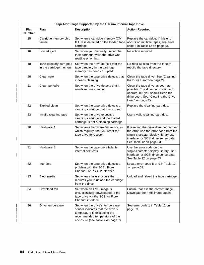
TapeAlert Flags Supported by the Ultrium Internal Tape Drive
FlagNumber
Flag Description Action Required
15 Cartridge memory chipfailure
Set when a cartridge memory (CM)failure is detected on the loaded tapecartridge.
Replace the cartridge. If this erroroccurs on multiple tapes, see errorcode 6 in Table 12 on page 53.
16 Forced eject Set when you manually unload thetape cartridge while the drive wasreading or writing.
No action required.
18 Tape directory corruptedin the cartridge memory
Set when the drive detects that thetape directory in the cartridgememory has been corrupted.
Re-read all data from the tape torebuild the tape directory.
20 Clean now Set when the tape drive detects thatit needs cleaning.
Clean the tape drive. See “Cleaningthe Drive Head” on page 27.
21 Clean periodic Set when the drive detects that itneeds routine cleaning.
Clean the tape drive as soon aspossible. The drive can continue tooperate, but you should clean thedrive soon. See “Cleaning the DriveHead” on page 27.
22 Expired clean Set when the tape drive detects acleaning cartridge that has expired.
Replace the cleaning cartridge.
23 Invalid cleaning tape Set when the drive expects acleaning cartridge and the loadedcartridge is not a cleaning cartridge.
Use a valid cleaning cartridge.
30 Hardware A Set when a hardware failure occurswhich requires that you reset thetape drive to recover.
If resetting the drive does not recoverthe error, use the error code from thesingle-character display, library userinterface, or SCSI drive sense data.See Table 12 on page 53.
31 Hardware B Set when the tape drive fails itsinternal self tests.
Use the error code on thesingle-character display, library userinterface, or SCSI drive sense data.See Table 12 on page 53.
32 Interface Set when the tape drive detects aproblem with the SCSI, FibreChannel, or RS-422 interface.
Locate error code 8 or 9 in Table 12on page 53.
33 Eject media Set when a failure occurs thatrequires you to unload the cartridgefrom the drive.
Unload and reload the tape cartridge.
34 Download fail Set when an FMR image isunsuccessfully downloaded to thetape drive via the SCSI or FibreChannel interface.
Ensure that it is the correct image.Download the FMR image again.
36 Drive temperature Set when the drive’s temperaturesensor indicates that the drive’stemperature is exceeding therecommended temperature of theenclosure (see Table 2 on page 7).
See error code 1 in Table 12 onpage 53.
84 IBM Ultrium Internal Tape Drive
|||||
|
|
|||||||
||

TapeAlert Flags Supported by the Ultrium Internal Tape Drive
FlagNumber
Flag Description Action Required
37 Drive voltage Set when the drive detects that theexternally supplied voltages areeither approaching the specifiedvoltage limits or are outside thevoltage limits (see Table 2 onpage 7).
See error code 2 in Table 12 onpage 53.
39 Diagnostics required Set when the drive detects a failurethat requires diagnostics to isolatethe problem.
See error code 6 in Table 12 onpage 53.
Appendix B. TapeAlert Flags 85
|||||
||

86 IBM Ultrium Internal Tape Drive

Notices
TrademarksThe following are trademarks of International Business Machines Corporation in theUnited States, or other countries, or both.
AIX iSeries SPAS/400 OS/400 StorageSmartEserver pSeries UltriumIBM RS/6000
The following are U.S. trademarks of Hewlett-Packard Company, InternationalBusiness Machines Corporation, and Seagate Technology.
Linear Tape-OpenLTOUltrium
Intel is a registered trademark of Intel Corporation in the United States, or othercountries, or both.
Microsoft, Windows, Windows NT, Windows 2000, and the Windows logo areregistered trademarks of Microsoft Corporation in the United States, or othercountries, or both.
Solaris and Sun are registered trademarks of Sun Microsystems Incorporated in theUnited States, or other countries, or both.
Other company, product, or service names may be the trademarks or service marksof others.
87
||||||||||||||

Electronic Emission Notices
Special Considerations for Electromagnetic CompatibilityModels T200 and T200F of the IBM Ultrium Internal Tape Drive have been found tosatisfy electromagnetic compatibility (EMC) requirements when they are installed ina suitably designed enclosure. Due to the high-performance and high-frequencyoperation of these drives, your enclosure must have sufficient EMC shielding andfiltering for the intended product class (A or B). It is the manufacturer’s responsibilityto ensure compliance to the required EMC standards by using appropriate testingand certification.
IBM Ultrium Internal Tape Drive Models T200 and T200FThe following statement applies to this product. The statement for other productsthat are intended for use with this product will appear in their accompanyingmanuals.
Federal Communications Commission (FCC) Class B StatementNote: This equipment has been tested and found to comply with the limits for aClass B digital device, pursuant to Part 15 of the FCC Rules. These limits aredesigned to provide reasonable protection against harmful interference in aresidential installation. This equipment generates, uses, and can radiate radiofrequency energy and, if not installed and used in accordance with the instructions,may cause harmful interference to radio communications. However, there is noguarantee that interference will not occur in a particular installation. If thisequipment does cause harmful interference to radio or television reception, whichcan be determined by turning the equipment off and on, the user is encouraged totry to correct the interference by one or more of the following measures:
v Reorient or relocate the receiving antenna.
v Increase the separation between the equipment and receiver.
v Connect the equipment into an outlet on a circuit different from that to which thereceiver is connected.
v Consult an IBM authorized dealer or service representative for help.
IBM is not responsible for any radio or television interference caused byunauthorized changes or modifications to this equipment. Unauthorized changes ormodifications could void the user’s authority to operate the equipment.
This device complies with Part 15 of the FCC Rules. Operation is subject to thefollowing two conditions: (1) this device may not cause harmful interference, and (2)this device must accept any interference received, including interference that maycause undesired operation.
Industry Canada Class B Emission Compliance StatementThis Class B digital apparatus complies with Canadian ICES-003.
Avis de conformité à la réglementation d’Industrie CanadaCet appareil numérique de la classe B est conform à la norme NMB-003 duCanada.
88 IBM Ultrium Internal Tape Drive
|
|||||||
European Union (EU) Electromagnetic Compatibility DirectiveThis product has been tested and found to comply with the limits for Class BInformation Technology Equipment according to European Standard EN 55022. Thelimits for Class B equipment were derived for typical residential environments toprovide reasonable protection against interference with licensed communicationdevices.
Germany Electromagnetic Compatibility DirectiveZulassungsbescheinigung laut dem Deutschen Gesetz über dieelektromagnetische Verträglichkeit von Geräten (EMVG) vom 30. August 1995(bzw. der EMC EG Richtlinie 89/336).
Dieses Gerät ist berechtigt, in Übereinstimmung mit dem Deutschen EMVG dasEG-Konformitätszeichen - CE - zu führen.
Verantwortlich für die Konformitätserklärung nach Paragraph 5 des EMVG ist dieIBM Deutschland Informationssysteme GmbH, 70548 Stuttgart.
Informationen in Hinsicht EMVG Paragraph 3 Abs. (2) 2: Das Gerät erfüllt dieSchutzanforderungen nach EN 50082-1 und EN 55022 Klasse B.
EN 50082-1 Hinweis: ″Wird dieses Gerät in einer industriellen Umgebung betrieben(wie in EN 50082-2 festgelegt), dann kann es dabei eventuell gestört werden. Insolch einem Fall ist der Abstand bzw. die Abschirmung zu der industriellenStörquelle zu vergrößern.″
Anmerkung: Um die Einhaltung des EMVG sicherzustellen, sind die Geräte wie inden IBM Handbüchern angegeben zu installieren und zu betreiben.
Japan VCCI Class B ITE Electronic Emission Statement
vcci-b
Notices 89

Getting HelpIf you need assistance while installing or operating your Ultrium Internal Tape Drive,refer to Table 14 and contact your nearest Customer Assistance Center. (Table tobe filled in by the OEM.)
Table 14. Telephone Numbers and e-mail Addresses for Customer Assistance Centers
World Wide Web Site:http://www.
Geographic LocationCustomer Assistance Center
Telephone e-mail
Americas
North America
South America
Hawaii
Guam
Europe, Middle East, Africa
United Kingdom
Austria
Belgium
France
Italy
Republic of Ireland
Netherlands
Germany
Sweden
Norway
Denmark
Finland
Asia Pacific
Japan
Australia
New Zealand
Other Asia Pacific locations
WarrantyThe warranty for this product is negotiated on a per-customer basis.
90 IBM Ultrium Internal Tape Drive
|||

Related PublicationsRefer to the following publications for additional information about the Ultrium TapeDrive. To ensure that you have the latest publications, visit the web athttp://www.ibm.com/storage/storagesmart/lto.
IBM Ultrium Publicationsv IBM Ultrium Internal Tape Drive Models T200 and T200F and IBM 3580 Ultrium
Tape Drive SCSI Reference, WB1109, provides the supported SCSI commandsand protocol that govern the behavior of the SCSI interface for the UltriumInternal Tape Drive Models T200 and T200F, and for the 3580 Ultrium TapeDrive.
v IBM Ultrium Device Drivers Installation and User’s Guide, GA32-0430, providesinstructions for attaching IBM-supported hardware to Open Systems operatingsystems. It indicates what devices and levels of operating systems aresupported, gives the requirements for adapter cards, and tells how to configureservers to use the device driver with the Ultrium family of devices.
v IBM Ultrium Device Drivers Programming Reference, WB1304, suppliesinformation to application owners who want to integrate their Open Systemsapplications with IBM-supported Ultrium hardware. The reference containsinformation about the application programming interfaces (APIs) for each of thevarious supported operating-system environments.
IBM Fibre Channel Publicationsv Fibre Channel Storage Hub IBM 2103 Model H07 Installation, Service, and
User’s Guide, SC26-7288
v IBM SAN Fibre Channel Switch 2109 Model S08 User’s Guide, SC26-7349
v IBM SAN Fibre Channel Switch 2109 Model S08 Installation and Service Guide,SC26-7350
v IBM SAN Fibre Channel Switch 2109 Model S16 User’s Guide, SC26-7351
v IBM SAN Fibre Channel Switch 2109 Model S16 Installation and Service Guide,SC26-7352
Other Publicationsv IBM Storage Area Network Gateway Module Setup, Operator, and Service Guide,
GA32-0436, describes the interface between devices and a storage area networkor Fibre Channel server. The guide gives instructions for installation andoperation of the unit, as well maintenance analysis procedures and a SCSIcommand reference.
Notices 91
|||||
|
||
|
||
|
||
|||||

Web SitesIBM Storage Media support:
v http://www.storage.ibm.com/media/how_buy.html
Provides access to current regional and country-specific IBM telephone numbers.
IBM Storage Products:
v http://www.storage.ibm.com/hardsoft/menu.htm
Furnishes documentation for IBM hardware products in a PDF format for viewingand printing.
Device Driver support:
v ftp://ftp.software.ibm.com/storage/devdrvr/
Provides device driver software that you can download.
92 IBM Ultrium Internal Tape Drive

Glossary
This glossary defines the special terms,abbreviations, and acronyms that are used in thispublication.
Numbers2:1 compression. The relationship between thequantity of data that can be stored with compression ascompared to the quantity of data that can be storedwithout compression. In 2:1 compression, twice asmuch data can be stored with compression as can bestored without compression.
AA. See ampere.
active. The condition that the SCSI bus is in when aserver is trying to use one or more devices on the bus.
adapter. See adapter card.
adapter card. A circuit board that adds function to acomputer.
AL_PA. See Arbitrated Loop Physical Address.
amp. See ampere.
ampere (A, amp). A unit of measure for electriccurrent that is equivalent to a flow of one coulomb persecond, or equivalent to the current produced by onevolt applied across a resistance of one ohm.
Arbitrated Loop Physical Address (AL_PA). An 8-bitvalue that identifies a device in an arbitrated loop. AllFibre Channel ports communicate by using AL_PAs.
autosense data. Sent by the drive to the server,sense data that automatically accompanies a CheckCondition in response to an error. The server does notneed to send a REQUEST SENSE command to get thesense data. Autosense data is available only in theFibre Channel version of the Ultrium Tape Drive (ModelT200F).
Bbackups. The short-term retention of records used forrestoring essential business and server files when vitaldata has been lost because of program or server errorsor malfunctions.
backreflection. Pertaining to instances where light islaunched into an optical fiber in a forward direction, thelight that is returned to the launch point in the reversedirection.
bar code. A code that represents characters by sets ofparallel bars of varying thickness and separation. Thebars are read optically by transverse scanning.
bar code label. A slip of paper bearing a bar code andhaving an adhesive backing. The bar code label mustbe affixed to a tape cartridge to enable the library toidentify the cartridge and its volume serial number.
bezel. The removable frame that fits over the front ofthe Ultrium Tape Drive.
burst data transfer rate. The maximum speed atwhich data is transferred.
bus. See SCSI bus.
byte. A string that consists of a certain number of bits(usually 8) which are treated as a unit and represent acharacter. A byte is a fundamental unit of data.
CC. See Celsius.
capacity. The amount of data that can be containedon storage media and expressed in bytes.
cartridge. See tape cartridge.
cartridge door. On a tape cartridge, the hinged barrierthat can be opened to access, or closed to protect, themagnetic tape within the cartridge.
cartridge manual rewind tool. A device that can befitted into the reel of a cartridge and used to rewind tapeinto or out of the cartridge.
cartridge memory. See LTO cartridge memory.
Celsius. Having a thermometric scale on which theinterval between the freezing point and the boiling pointof water is divided into 100 degrees, with 0°representing the freezing point and 100° representingthe boiling point.
circuit board. A thin sheet on which chips and otherelectronic components are placed. Computers consist ofone or more boards, often called cards or adapters.
cleaning cartridge. A tape cartridge that is used toclean the heads of a tape drive. Contrast with datacartridge.
clockwise. In the direction that the hands of a clockrotate, as viewed from the front.
93
|
|
|||
|
||||||
|
|
||
|
||
|
|
||||
|||
|||||||
|
||||
||||
|||
||||
||
||
|
|||
|
|
||
|
|||
|||
|
|||||
|||
|||
||

command time-out. Following the issuance of acommand, a period of time during which it is determinedthat there is a bad connection between the server andthe drive.
compression. The process of eliminating gaps, emptyfields, redundancies, and unnecessary data to shortenthe length of records or blocks.
configure. To describe to a server the devices,optional features, and programs installed on the system.
contiguous. Touching along a boundary or at a point.
core. The light-conducting central portion of an opticalfiber. The core is composed of material that has ahigher index of refraction than the cladding (the materialthat surrounds the core).
counterclockwise. In a direction opposite to that inwhich the hands of a clock rotate, as viewed from thefront.
current. The quantity of charge per unit of time.Current is measured in amperes.
cycle power. To apply and remove electrical power toa device within a short time span.
Ddata. Any representations such as characters oranalog quantities to which meaning is, or might be,assigned.
data cartridge. A tape cartridge that is dedicated tostoring data. Contrast with cleaning cartridge.
data compression. See compression.
data transfer rate. The average number of bits,characters, or blocks per unit of time that pass betweencorresponding equipment in a data transmission system.The rate is expressed in bits, characters, or blocks persecond, minute, or hour.
dc. Direct current.
degauss. To make a magnetic tape nonmagnetic byexposing the tape to electrical coils which carry currentsthat neutralize the magnetism of the tape.
device. Any hardware component or peripheral, suchas a tape drive or tape library, that can receive andsend data.
device driver. A file that contains the firmware that isneeded to use an attached device.
diagnostic. A software program that is designed torecognize, locate, and explain faults in equipment orerrors in programs.
diagnostic cartridge. A tape cartridge that enablesthe detection and isolation of errors in programs andfaults in equipment.
direct current (dc). An electric current flowing in onedirection only and substantially constant in value.
drive. See Ultrium Internal Tape Drive.
drive dump. The recording, at a particular instant, ofthe contents of all or part of one storage device intoanother storage device, usually as a safeguard againstfaults or errors, or in connection with debugging.
drive head. The component that records an electricalsignal onto magnetic tape, or reads a signal from tapeinto an electrical signal.
drive sense data. See SCSI drive sense data.
dump. See drive dump.
duplex. See duplex transmission.
duplex adapter. A mechanism that allows a device tosend and receive communication at the same time.
duplex transmission. Transmission in both directions,either one direction at a time (half-duplex) or bothdirections simultaneously (full-duplex).
Eeject. To remove or force out from within.
electronic mail. Correspondence in the form ofmessages transmitted between user terminals over acomputer network.
e-mail. See electronic mail.
enclosure. A device, such as a desktop unit, tapecartridge autoloader, or tape library, into which you caninstall the Ultrium Tape Drive.
error log. Maintained by the Ultrium Tape Drive, a listthat contains the ten most recent error codes. Thecodes identify errors that pertain to the drive.
Ffan shroud. The wire mesh enclosure around the fanthat holds it in place and prevents direct access. Theshroud mounts the fan assembly to the Ultrium TapeDrive.
feature switch. Located under the Ultrium Tape Drive,a bank of eight micro switches that can be manuallytoggled on or off to activate or deactivate differentcharacteristics of the drive.
94 IBM Ultrium Internal Tape Drive
||||
|||
||
|
||||
|||
||
||
|
|||
||
|
|||||
|
|||
|||
||
|||
|||
||
|
||||
|||
|
|
|
||
|||
|
|
|||
|
|||
|||
|
||||
||||

fiber optic cable. The medium by which light istransmitted through fibers or thin rods of glass or someother transparent material of high refractive index.
fiber optics. A branch of optics dealing with thetransmission of light through fibers or thin rods of glassor some other transparent material of high refractiveindex.
Fibre Channel. A 100-MB-per-second, full-duplex,serial communications technology that is capable ofinterconnecting Ultrium Tape Drives and servers whichare separated by as much as 11 kilometers (7 miles).Fibre Channel technology combines features of theinput/output (I/O) and networking interfaces.
Fibre Channel address. For a tape drive that uses aFibre Channel interface, an identifier (such as an AL_PAor Loop ID) that enables other device ports tocommunicate with that drive. A Fibre Channel drive hasa 3-byte address. The switch assigns the upper 2 bytesof the address. If no switch is attached, the 2 bytesequal 0. The lower byte assignment (which is theAL_PA) varies, depending on whether hard or softaddressing is used.
Fibre Channel cable. The cable that connects a FibreChannel tape drive to another device. The conductiveelement within the cable is constructed of either copperwires or optical fibers. Generally, copper wires are usedfor short distances (up to 30 meters or 98 feet); opticalfibers are used for longer distances. Fiber-optic cablingis referred to by mode or the frequencies of light wavesthat are carried by a particular cable type. Multimodefiber cables are generally used for distances up to 500meters (1640 feet) and with short-wave (780nanometer) laser light. Single-mode fiber cables areused for distances greater than 500 m (1640 feet) andwith long-wave (1300 nanometer) laser light.
Fibre Channel wrap test. A diagnostic that causes theUltrium Tape Drive to perform a check of the FibreChannel circuitry from and to the drive’s Fibre Channelconnector or the fiber cable.
field microcode replacement tape. A tape cartridgethat contains new or revised firmware (microcode) forthe Ultrium Tape Drive.
file. A named set of records that are stored orprocessed as a unit.
filemark. Located on the magnetic tape within a tapecartridge, a recorded element that typically marks theorganizational boundaries in a serial file structure (suchas directory boundaries) and that is requested to bewritten or read by the server.
firmware. Proprietary code that is usually delivered aspart of an operating system. Firmware is more efficientthan software that is loaded from an alterable medium,and is more adaptable to change than pure hardwarecircuitry. An example of firmware is the Basic
Input/Output System (BIOS) in read-only memory(ROM) on a PC motherboard.
FMR tape. See field microcode replacement tape.
foot. A unit of length comprising 12 inches.
GGB. See gigabyte.
gigabyte (GB). 1 000 000 000 bytes.
ground. An object that makes an electrical connectionwith the earth.
Hhard addressing. Pertaining to the Fibre Channeldrive (Model T200F), a method that identifies the drive’sLID and, consequently, its AL_PA (the AL_PA enablesthe drive to communicate with other devices).
hardware. The physical equipment or devices thatform a computer.
head. See drive head.
Head Resistance Measurements test. Part of theTest Head diagnostic, a procedure that determineswhether the tape drive’s head works correctly. The testmeasures the head’s ability to withstand cracks andother defects.
host. The controlling or highest-level system in a datacommunication configuration. Synonymous with server.
hot-pluggable. Pertaining to the Ultrium Tape Drive,the ability to remove the drive from an enclosure whilethe enclosure is powered-on.
hub. A communications device to which nodes on amulti-point bus or loop are physically connected. Hubsare commonly used in Fibre Channel networks toimprove the manageability of physical cables. Theymaintain the logical loop topology of the network ofwhich they are a part, while creating a “hub and spoke”physical star layout. Unlike switches, hubs do notaggregate bandwidth. They typically support the additionor removal of nodes from the bus while it is operating.
IIBM Ultrium Internal Tape Drive. See Ultrium InternalTape Drive.
ID. Identifier.
in. See inch.
inch. A unit of length equal to 1/36 yard or 25.4 mm.
Glossary 95
|||
||||
||||||
|||||||||
|||||||||||||
||||
|||
||
|||||
|||||
||
|
|
|
|
|
||
|
||||
||
|
|||||
||
|||
|||||||||
|
||
|
|
|

initiator. In SCSI terms, a SCSI device that requestsan I/O process to be performed by another SCSI device(a target). In many cases, an initiator can also be atarget.
input/output (I/O). Data that is provided to a computeror data that results from computer processing.
insertion guide. On the surface of the IBM LTOUltrium Tape Cartridge, a large, notched area thatprevents you from inserting the cartridge incorrectly.
install. (1) To set up for use or service. (2) The act ofadding a product, feature, or function to a server ordevice either by a singular change or by the addition ofmultiple components or devices.
Internet. The worldwide collection of interconnectednetworks that use the Internet suite of protocols andpermit public access.
interposer. An adapter-like device that allows aconnector of one size and style to connect to a matingconnector of a different size and style. Data provided tothe computer or data resulting from computerprocessing.
I/O. See input/output.
JJ1 connector. Located at the rear of the Ultrium TapeDrive, a single connector that contains the connectionsfor the SCSI signals and grounds, SCSI ID, SCSI bustermination, and drive power.
J2 connector. Located at the rear of the Ultrium TapeDrive, the connector for the RS-422 interface.
jumper. (1) A tiny connector that fits over a pair ofprotruding pins in a connector. A jumper can be movedto change electrical connectors. When in place, thejumper connects the pins electrically. (2) To place ajumper on a connector pin.
Llabel. A slip of paper with an adhesive backing thatcan be written on and affixed to a tape cartridge as ameans of identification or description.
label area. On the LTO Ultrium Tape Cartridge, arecessed area next to the write-protect switch where abar code label must be affixed.
LAN. See local area network.
leader-pin block. Located within the Ultrium TapeDrive, the part that engages the steel pin which isattached to the tape in an LTO Ultrium Tape Cartridge.Once engaged, the leader-pin block pulls the tape fromthe cartridge into the drive.
leader pin. On the LTO Ultrium Tape Cartridge, asmall metal column that is attached to the end of themagnetic tape. During tape processing the leader pin isgrasped by a threading mechanism, which pulls the pinand the tape out of the cartridge, across the drive head,and onto a takeup reel. The head can then read or writedata from or to the tape.
LED. See light-emitting diode.
LID. See loop identifier.
LID/status connector. See loop identifier (LID)/statusconnector.
LIP. See loop initialization protocol.
light-emitting diode (LED). A semiconductor diodethat emits light when subjected to an applied voltageand that is used in an electronic display.
Linear Tape-Open (LTO). A type of tape storagetechnology developed by the IBM Corporation,Hewlett-Packard, and Seagate. LTO technology is an“open format” technology, which means that its usershave multiple sources of product and media. The “open”nature of LTO technology enables compatibility betweendifferent vendors’ offerings by ensuring that vendorscomply with verification standards.
load. Following the insertion of a tape cartridge intothe tape load compartment, the act of positioning thetape (performed by the tape drive) for reading or writingby the drive’s head.
load and unload cycle. The act of inserting acartridge into a tape drive, loading the tape to loadpoint, rewinding the tape into the cartridge, and ejectingthe cartridge from the drive.
local area network (LAN). A computer network that islocated on a user’s premises within a limitedgeographical area. The network consists of a set ofdevices that are connected to one another forcommunication and that can be connected to a largernetwork. Communications are limited to amoderate-sized geographic area (1 to 10 km) such as asingle office building, warehouse, or campus.
log sense data. See SCSI log sense data.
loop. (1) A series of instructions that is repeated until aterminating condition is reached. (2) To connect so as tocomplete a loop.
loop ID. See loop identifier.
loop identifier (LID). In a Fibre Channel topology, theidentifier that a device assigns to an Ultrium Tape Drive.An operator uses the LID to set the AL_PA.
loop identifier (LID)/status connector. Located onthe Model T200F, the connector that is used to set theLoop ID and provide status about the loop.
96 IBM Ultrium Internal Tape Drive
||||
||
|||
||||
|||
|||||
|
|
||||
||
|||||
|
|||
|||
|
|||||
|||||||
|
|
||
|
|||
||||||||
||||
||||
||||||||
|
|||
|
|||
|||

loop initialization protocol (LIP). A method by whicha device in a Fibre Channel Arbitrated Loop acquires itsAL_PA.
loss. In fiber optics technology, the amount of asignal’s power (expressed in dB) that is lost inconnectors, splices, or fiber defects.
Low Voltage Differential (LVD). A low-noise,low-power, and low-amplitude electrical signaling systemthat enables data communication between a supportedserver and the Ultrium Tape Drive. LVD signaling usestwo wires to drive one signal over copper wire. The useof wire pairs reduces electrical noise and crosstalk.
LTO. See Linear Tape-Open.
LTO cartridge memory (LTO-CM). Within each LTOUltrium Data Cartridge, an embedded electronics andinterface module that can store and retrieve acartridge’s historical usage and other information.
LTO-CM. See LTO cartridge memory.
LVD. See Low Voltage Differential.
Mm. See meter.
magnetic tape. A tape with a magnetizable surfacelayer on which data can be stored by magneticrecording.
maintenance mode. The state of operation in whichthe Ultrium Tape Drive must be before it can rundiagnostics, verify write and read operations, verify asuspect tape cartridge, update its own firmware, andperform other diagnostic and maintenance functions.
MB. See megabyte.
media. The plural of medium.
media capacity. See capacity.
medium. A physical material in or on which data maybe represented, such as magnetic tape.
megabyte (MB). 1 000 000 bytes.
metal particle tape. In the LTO Ultrium TapeCartridge, tape that uses very small, pure metalparticles (rather than oxide coatings) in the magneticlayer.
meter. In the Metric System, the basic unit of length;equal to approximately 39.37 inches.
micrometer. One millionth of a meter (.000001 m).Synonymous with micron. Abbreviated as µm.
micron. One millionth of a meter (.000001 m).Synonymous with micrometer. Abbreviated as µm.
millimeter. One thousandth of a meter (.001 m).
mm. See millimeter.
Model T200. The version of the Ultrium Internal TapeDrive that uses the SCSI interface.
Model T200F. The version of the Ultrium Internal TapeDrive that uses the Fibre Channel interface.
multimode fiber. An optical fiber that has a core thatis large enough to propagate more than oneelectromagnetic wave of light. The typical diameter is62.5 micrometers.
NN/A. Not applicable.
native storage capacity. The amount of data that canbe stored without compression on a tape cartridge.
native sustained data transfer rate. See datatransfer rate.
network. A configuration of data processing devicesand software that is connected for informationinterchange.
network server. In a local area network, a personalcomputer that provides access to files for all of theworkstations in the network.
node. In Fibre Channel technology, a communicatingdevice.
ntutil. Created by IBM, a utility program for LTOdevices that connect to Windows NT and Windows2000. ntutil provides problem determination forhardware or connections, assists with device andmedium changer recognition, forces dumps, loads newfirmware, sends and receives SCSI commands to andfrom the hardware, and obtains SCSI sense data to usein resolving errors.
Ooersted. The unit of magnetic field strength in theunrationalized centimeter-gram-second (cgs)electromagnetic system. The oersted is the magneticfield strength in the interior of an elongated, uniformlywound solenoid that is excited with a linear currentdensity in its winding of one abamper per 4πcentimeters of axial length.
offline. The operating condition that the Ultrium TapeDrive is in when the server’s applications cannot interactwith it.
online. The operating condition that the Ultrium TapeDrive is in when the server’s applications can interactwith it.
Glossary 97
|||
|||
||||||
|
||||
|
|
|
|
|||
|||||
|
|
|
||
|
||||
||
||
||
|
|
||
||
||||
|
|
||
||
|||
|||
||
||||||||
|
|||||||
|||
|||

Open Systems. Computer systems whose standardsare not proprietary.
operating environment. The temperature, relativehumidity rate, and wet bulb temperature of the room inwhich the Ultrium Tape Drive routinely conductsprocessing.
operating system. The master computer controlprogram that translates the user’s commands andallows software application programs to interact with thecomputer’s hardware.
optical transceiver. A device that both transmits andreceives analog or digital signals over a light source.
Pparity. The state of being even-numbered orodd-numbered. A parity bit is a binary number that isadded to a group of binary numbers to make the sum ofthat group always odd (odd parity) or even (even parity).
parity error. A transmission error that occurs when thereceived data does not have the parity that is expectedby the receiving system. This usually occurs when thesending and receiving systems have different paritysettings.
port. (1) A system or network access point for dataentry or exit. (2) A connector on a device to whichcables for other devices such as display stations andprinters are attached. (3) The representation of aphysical connection to hardware. A port is sometimesreferred to as an adapter; however, there can be morethan one port on an adapter.
power connector. Located at the rear of the UltriumTape Drive, the connector to which the internal powercable of an enclosure connects.
power cord. A cable that connects a device to asource of electrical power.
power-off. To remove electrical power from a device.
power-on, powered-on. (1) To apply electrical powerto a device. (2) The state of a device when power hasbeen applied to it.
protocol. The meanings of, and the sequencing rulesfor, requests and responses that are used to manage anetwork, transfer data, and synchronize the states ofnetwork components.
Qquiesce. To put a device into a temporarily inactive orinhibited state, but not remove it from the server.
Rread. To acquire or interpret data from a storagedevice, from a data medium, or from another source.
reboot. To reinitialize the execution of a program byrepeating the initial program load (IPL) operation.
record. The smallest distinct set of data bytes that issupplied from a server for processing and recording bya tape drive, and the smallest distinct set of data to beread from tape, reprocessed, and made available to aserver by a tape drive.
record boundaries. The fixed limits of a record.
relative humidity. The ratio of the amount of watervapor actually present in the air to the greatest amountpossible at the same temperature.
repeater. A device that regenerates signals to extendthe range of transmission between data stations or tointerconnect two branches. A repeater is a node of alocal area network.
reset. To return a device or circuit to a clear state.
RS-422 connector. Located at the rear of the UltriumTape Drive, the connector to which the internal RS-422cable of an enclosure connects. The connection enablesserial devices to communicate with the drive.
RS-422 interface. An electrical interface standard thatis approved by the Electronic Industries Association(EIA) for connecting serial devices. The RS-422standard, which supports higher data rates and greaterimmunity to electrical interference, is an alternative tothe older RS-232 interface, and uses individualdifferential signal pairs for data transmission. Dependingon data transmission rates, RS-422 can be used atdistances up to 1,275 m (4,000 ft). The RS-422interface also supports multi-point connections.
RS-422 wrap plug. A connector mechanism thatconnects to an RS-422 port for the purpose of testingthe Ultrium Tape Drive’s circuitry for the RS-422interface.
RS-422 wrap test. A diagnostic that can be run on theUltrium Tape Drive to determine whether the circuitryfunctions properly to and from the RS-422 connector.
SSAN. See Storage Area Network.
SAN Data Gateway. A device that provides FibreChannel attachment between Open Systems serversand SCSI disk and tape storage systems.
SC. See subscription channel connector.
98 IBM Ultrium Internal Tape Drive
||
||||
||||
||
|
||||
|||||
|||||||
|||
||
|
|||
||||
|
||
|
||
||
|||||
|
|||
||||
|
||||
||||||||||
||||
|||
|
|
|||
|

scratch cartridge. A data cartridge that contains nouseful data, but can be written to with new data.
SCSI. See Small Computer Systems Interface.
SCSI bus. (1) A collection of wires through which datais transmitted from one part of a computer to another.(2) A generic term that refers to the complete set ofsignals that define the activity of the Small ComputerSystems Interface (SCSI).
SCSI connector. Located at the rear of the UltriumTape Drive, the connector that facilitates commands toand from the server, and to which the internal SCSIcable of an enclosure connects.
SCSI device. Anything that can connect into the SCSIbus and actively participate in bus activity.
SCSI drive sense data. In response to inquiry fromthe server about an error condition, a packet of SCSIsense bytes that contains information about the errorand that is sent back to the server by the drive.
SCSI ID. The unique address (from 1 to 15) that youassign to an Ultrium Tape Drive that uses a SCSIinterface (Model T200).
SCSI ID connector. Located at the rear of the UltriumTape Drive, the connector that enables the drive’s SCSIaddress to be set. Addresses are determined by theplacement of jumpers on the pins.
SCSI ID switch. Located on an enclosure thatcontains a Ultrium Tape Drive, a mechanism thatconnects to the drive and allows you to change thedrive’s SCSI ID without using jumpers.
SCSI log sense data. In response to inquiry from theserver about the Ultrium Tape Drive’s error logs andcounters, a packet of SCSI sense bytes which containsthat information and which is sent back to the server bythe drive. Log sense data is used to diagnose problems,especially if the problems are intermittent.
SCSI wrap plug. A connector mechanism thatconnects to a SCSI port for the purpose of testing theUltrium Tape Drive’s circuitry for the SCSI interface.
SCSI wrap test. A diagnostic that can be run on theUltrium Tape Drive to determine whether the circuitryfunctions properly to and from the SCSI connector.
selection time-out. Following the selection of anoption (for example, a data transfer), the period of timeduring which it is determined that there is a badconnection between the server and the drive.
sense data. Data that describes an I/O error. Sensedata is presented to a server in response to a SenseI/O command.
serial interface. An interface that sequentially orconsecutively executes two or more operations in asingle device, such as an arithmetic and logic operation.
server. A functional unit that provides services to oneor more clients over a network. Examples include a fileserver, a print server, or a mail server. The IBMEserver pSeries, IBM Eserver iSeries, HP, and Sunare servers. Synonymous with host.
ship group. The group of supplies, cords, ordocumentation that is shipped with the Ultrium TapeDrive.
shipping environment. The temperature, relativehumidity rate, and wet bulb temperature of theenvironment to which the Ultrium Tape Drive is exposedwhen it is transferred from one location to another.
short-wave cable. In Fibre Channel technology, alaser cable that uses a wavelength of 780 nanometersand is only compatible with multimode fiber.
single-character display. Located at the front of theUltrium Tape Drive, an LED that presents analphabetical or numeric code which represents adiagnostic or maintenance function, error condition, orinformational message.
Small Computer Systems Interface (SCSI). Astandard used by computer manufacturers for attachingperipheral devices (such as tape drives, hard disks,CD-ROM players, printers, and scanners) to computers(servers). Pronounced ″scuzzy.″ Variations of the SCSIinterface provide for faster data transmission rates thanstandard serial and parallel ports (up to 160 megabytesper second). The variations include:
v Fast/Wide SCSI: Uses a 16-bit bus, and supportsdata rates of up to 20 MBps.
v SCSI-1: Uses an 8-bit bus, and supports data ratesof 4 MBps.
v SCSI-2: Same as SCSI-1, but uses a 50-pinconnector instead of a 25-pin connector, andsupports multiple devices.
v Ultra SCSI: Uses an 8- or 16-bit bus, and supportsdata rates of 20 or 40 MBps.
v Ultra2 SCSI: Uses an 8- or 16-bit bus and supportsdata rates of 40 or 80 MBps.
v Ultra3 SCSI: Uses a 16-bit bus and supports datarates of 80 or 160 MBps.
soft addressing. Pertaining to the Fibre Channel drive(Model T200F), a method that enables the drive todynamically arbitrate its AL_PA with other Fibre Channeldevices on the loop. The AL_PA enables the drive tocommunicate with other devices.
software. Programs, procedures, rules, and anyassociated documentation pertaining to the operation ofa computer system.
Glossary 99
||
|
|||||
||||
||
||||
|||
||||
||||
||||||
|||
|||
||||
|||
|||
|||||
|||
||||
|||
|||||
||||||||
||
||
|||
||
||
||
|||||
|||

status light. Located at the front of the Ultrium TapeDrive, an LED that can be green or amber, and (whenlit) solid or flashing. The condition of the light representsthe state of the drive.
Storage Area Network (SAN). A high-speedsubnetwork of shared storage devices. A SAN’sarchitecture makes all storage devices available to allservers on a LAN or WAN. As more storage devices areadded to a SAN, they too will be accessible from anyserver in the larger network. Because stored data doesnot reside directly on any of a network’s servers, serverpower is used for business applications, and networkcapacity is released to the end user.
storage environment. The temperature, relativehumidity rate, and wet bulb temperature of theenvironment in which the Ultrium Tape Drive isnonoperational and is being kept for future use.
subscription channel connector (SC). A push-pulltype of optical connector that features high density, lowloss, low backreflection, and low cost.
switch. A network infrastructure component to whichmultiple nodes attach. Unlike hubs, switches typicallyhave the ability to switch node connections from one toanother. A typical switch can facilitate severalsimultaneous bandwidth transmissions between differentpairs of nodes.
TTapeAlert. A patented technology and ANSI standardthat defines conditions and problems that areexperienced by tape drives.
TapeAlert flags. Status and error messages that aregenerated by the TapeAlert utility and display on theserver’s console.
tape cartridge. A removable storage case that housesbelt-driven magnetic tape that is wound on a supply reeland a takeup reel.
tape drive. See Ultrium Internal Tape Drive.
tape path. Within a tape drive, the channel in whichthe media moves.
tapeutil. Created by IBM, a utility program for LTOdevices that connect to all supported servers exceptWindows NT and Windows 2000. tapeutil providesservice aids for tape subsystems, offers a menu-driventool for exercising or testing IBM tape and mediumchanger devices, and includes a command-line interfacethat is convenient for use in shell scripts.
terminate. To prevent unwanted electrical signalreflections by applying a device (known as a terminator)that absorbs the energy from the transmission line.
terminator. (1) A part that is used to end a SCSI bus.(2) A single-port, 75-B device that is used to absorbenergy from a transmission line. Terminators preventenergy from reflecting back into a cable plant byabsorbing the radio frequency signals. A terminator isusually shielded, which prevents unwanted signals fromentering or valid signals from leaving the cable system.
TERMPOWER. Electrical power that is provided by adevice (such as the Ultrium Tape Drive) to a SCSIterminator so that the SCSI bus can function. To supplyTERMPOWER, a jumper must be placed on pin 1 of theSCSI ID connector on the Ultrium Tape Drive.
Test Head diagnostic. A test that determines whetherthe heads of the Ultrium Tape Drive are operatingproperly and whether the drive can correctly read fromand write to tape.
topology. In communications, the physical or logicalarrangement of nodes in a network, especially therelationships among nodes and the links between them.
track. A linear or angled pattern of data that is writtenon a tape surface.
transfer rate. See data transfer rate.
two-node arbitrated loop. In Fibre Channeltechnology, the connection of two nodes thatcommunicate directly (without the use of a switch) anduse the same protocol.
two-node switched fabric loop. In Fibre Channeltechnology, the connection of two or more nodes thatcommunicate by using a switch. The nodes may not usethe same protocol.
UUltrium Tape Drive. See Ultrium Internal Tape Drive.
uniform resource locator (URL). The address of anitem on the World Wide Web. It includes the protocolfollowed by the fully qualified domain name (sometimescalled the host name) and the request. The web servertypically maps the request portion of the URL to a pathand file name. For example, if the URL ishttp://www.networking.ibm.com/nsg/nsgmain.htm, theprotocol is http; the fully qualified domain name iswww.networking.ibm.com; and the request is/nsg/nsgmain.htm.
unload. The act (performed by the drive) ofunthreading tape from the drive’s internal tape path andreturning it (with the leader block) to the tape cartridge.
unload button. Located at the front of the UltriumTape Drive, a push button that, when depressed,rewinds the tape in a cartridge and ejects the cartridgefrom the drive. The unload button can also be used toplace the tape drive in maintenance mode, scroll
100 IBM Ultrium Internal Tape Drive
||||
|||||||||
||||
|||
||||||
|
|||
|||
|||
|
||
|||||||
|||
|||||||
|||||
||||
|||
||
|
||||
||||
|
|
||||||||||
|||
|||||

through maintenance functions, exit maintenance mode,force a drive dump, and reset the drive.
Ultrium Internal Tape Drive. A data-storage devicethat controls the movement of the magnetic tape in anIBM LTO Ultrium Tape Cartridge. The drive houses themechanism (drive head) that reads and writes data tothe tape. The drive is the first of four drives planned forthe Ultrium format. Its native data capacity is 100 GBper cartridge; with 2:1 compression, its capacity is up to200 GB.
URL. See uniform resource locator.
utility. See utility program.
utility program. A computer program that supportscomputer processes. For example, a diagnosticprogram, a trace program, or a sort program.
VVdc. Volts dc (direct current).
vital product data (VPD). Information about a product.Among other details, the VPD may include a modelnumber, serial number, part number, or level offirmware.
volt. The SI (international) unit of potential differenceand electromotive force. Formally defined as thedifference of electric potential between two points of aconductor that carries a constant current of one amperewhen the power dissipated between these points isequal to one watt.
VPD. Vital product data.
WW. Watts.
WAN. See wide area network.
watt. The metric unit of power that is required to dowork at the rate of one joule per second.
web. See World Wide Web.
wet bulb temperature. The temperature at which purewater must be evaporated adiabatically at constantpressure into a given sample of air in order to saturatethe air under steady-state conditions. Wet bulbtemperature is read from a wet bulb thermometer.
wide area network (WAN). A data communicationsnetwork that is designed to serve an area of hundredsor thousands of miles (for example, national telephonenetworks).
World Wide Name. A unique, 8-byte identifier that isassigned by IBM Manufacturing to each Ultrium TapeDrive and used to identify a drive.
World Wide Web. A network of servers that containprograms and files. Many of the files contain hypertextlinks to other documents that are available through thenetwork.
write. To make a permanent or transient recording ofdata in a storage device or on a data medium.
write protected. Applicable to a tape cartridge, thecondition that exists when some logical or physicalmechanism prevents a device from writing on the tapein that cartridge.
write-protect switch. Located on the LTO UltriumTape Cartridge, a switch that prevents accidentalerasure of data. Pictures of a locked and unlockedpadlock appear on the switch. When you slide theswitch to the locked padlock, data cannot be written tothe tape. When you slide the switch to the unlockedpadlock, data can be written to the tape.
Write/Read test. Part of the Test Head diagnostic, aprocedure that determines whether the Ultrium TapeDrive can correctly read from and write to tape.
Glossary 101
||
||||||||
|
|
|||
|
|
||||
||||||
|
|
|
|
||
|
|||||
||||
|||
||||
||
||||
|||||||
|||

102 IBM Ultrium Internal Tape Drive

Index
Numerics2103 Fibre Channel hub 32103 Fibre Channel switches 3
Aacclimating the drive 23, 48address
for Fibre Channel drive 4, 15for SCSI drive 2, 14
airflow in tape drive 11AL_PA
description 15setting to add LIDs 4, 18setting to get status of loop 16
altitude specification 7Arbitrated Loop Physical Address (AL_PA)
description 4, 15setting to add LIDs 18setting to get status of loop 16
AS/400obtaining error information from 59supported operating system
supported by Fibre Channel drive 3supported by SCSI drive 2
attaching leader pin to tape, procedure 44attention notice, definition v
Bbar code label
ordering 50placement on cartridge 42
bulk erasure 48bus, connecting tape drive to SCSI 22
Ccables
for Fibre Channel 4, 81for SCSI 2, 81
capacity 1, 2, 42cartridge memory 42caution notice, definition vcheckout of tape drive, performing 21circuits, cooling requirements 11cleaning cartridge
description 42ordering 50
cleaning drive head 27clearing error code log 35compatible tape cartridges 2compressed capacity 1, 42compression algorithm 1configuring tape drive to server, switch, or hub 22connections
Fibre Channel 22
connections (continued)hot-pluggable 21power 21RS-422 interface 21SCSI bus 22
connectorsFibre Channel 1, 4, 11SCSI 1, 2, 10
converting an FMR tape to a scratch tape 34cooling fan assembly, installing
Fibre Channel drive 13SCSI drive 12
cooling requirements for circuits 11copying a drive dump to tape 31creating an FMR tape 30current, electrical specifications 7Customer Assistance Centers 90
Ddanger notice, definition vdata cartridge 42, 50data transfer rate 1degaussing a tape cartridge 48, 49description of Ultrium Tape Drive 1device driver
use in recording errors 59use with server 1
diagnosticsfast read/write test 36Fibre Channel wrap test 33RS-422 wrap test 33SCSI wrap test 32selecting 28Test Cartridge & Media 35, 69Test Head 36
dimension of tape 2dimension of tape drive 7displaying error code log 34, 64disposing of a tape cartridge 49drive dump
copying to tape 31forcing 25, 30obtaining 63
drive head, cleaning 27
Eejecting a tape cartridge 25electronic emission regulations 88enclosure
hot-pluggable connection 21mounting the tape drive into 20powering off 11
environmental specificationsfor media 49for tape drive 7
103
|
|

erasing tape 48error code log
clearing 35displaying 34viewing 64
errorsdescriptions and corrective actions 53Fibre Channel 67media 69methods of receiving 53obtaining from AS/400 or iSeries servers 59obtaining from RS/6000 or pSeries servers 60reported to server 59, 65reported to enclosure 53reported to tape drive error log 64SCSI bus 65TapeAlert flags 83troubleshooting tips 51using sense data 59
exiting maintenance mode 25, 37
Ffabric, switched 4fan, installing cooling
Fibre Channel drive 13SCSI drive 12
fast read/write test 36FCC statement 88Federal Communications Commission (FCC)
statement 88Fibre Channel drive
assigning an address 4cables 4connector 1, 4errors, fixing 67ID, setting 15installing 5rear view 11removing 5resetting 5, 25supported topologies 4use of SCSI protocol 1World Wide Name 5wrap test 33
firmwarerecovery from error 24updating
from FMR tape 24, 29, 39through SCSI bus, Fibre Channel, or RS-422
interface 24, 38fixing an internal jam 76FMR tape
converting to scratch tape 34creating 30updating firmware from 29, 39
forcing a drive dump 25, 30
Ggetting help 90
Hhard addressing 4head, testing 36height of tape drive 7help, getting 90host sense data 59hot-pluggable connection 21HP
supported by Fibre Channel drive 3supported by SCSI drive 2
IID, setting loop 15ID, setting SCSI 14inserting a tape cartridge 26installing the cooling fan assembly
Fibre Channel drive 13SCSI drive 12
installing the Ultrium Tape DriveFibre Channel drive (Model T200F) 5, 9SCSI drive (Model T200) 3, 9
Intel-based PCssupported by Fibre Channel drive 3supported by SCSI drive 2
internal jam, fixing 76iSeries server
obtaining error information from 59supported operating system
Fibre Channel drive 3SCSI drive 2supported by Fibre Channel drive 3supported by SCSI drive 2
JJ1 connector 1, 11
Llabel, for Ultrium Tape Cartridge 42label area, on Ultrium Tape Cartridge 42laser safety notice vileader pin, in tape cartridge 42leader pin, reattaching to tape 44leader pin reattachment kit 45, 81length of tape drive 7LID 15
description 4, 15setting to add LIDs 15, 18setting to get status of loop 15, 16
Linear Tape-Open (LTO) Cartridge Memory (CM) 42Linux
supported by Fibre Channel drive 3supported by SCSI drive 2
load and unload cycle life for data cartridge 42loading a tape cartridge 26loop identifier (LID)
description 4, 15setting to add LIDs 15, 18
104 IBM Ultrium Internal Tape Drive
|

loop identifier (LID) (continued)setting to get status of loop 15, 16
LTO Data Compression (LTO-DC) algorithm 1
Mmaintenance functions
clearing error code log 35converting an FMR tape to a scratch tape 34copying drive dump to tape 31creating FMR tape 30displaying error code log 34forcing drive dump 30inserting cartridge into tape drive 35selecting 28updating firmware from FMR tape 29
maintenance modeexiting 25, 37placing the tape drive in 25, 27selecting a maintenance or diagnostic function 25,
28manual rewind tool, ordering 81manually removing a tape cartridge from the drive 73media, using 41media-related errors 69models of Ultrium Tape Drive 1mounting tape drive into an enclosure 20
Ooperating systems, supported
for Fibre Channel drive 3for SCSI drive 2
operating the tape drive 23ordering tape cartridges and supplies 50
Pplacing the tape drive in maintenance mode 25, 27power
connecting to tape drive 21hot-pluggable connection 21specifications 7
powering off the enclosure 11problems, resolving 53pSeries server
obtaining error information from 60supported operating system
Fibre Channel drive 3SCSI drive 2supported by Fibre Channel drive 3supported by SCSI drive 2
Rread/write capability 2rear view
Fibre Channel drive 11SCSI drive 10
recording method, of tape drive 2, 42
relative humidity specificationsfor media 49for tape drive 7
removing the tape drive from an enclosureFibre Channel drive 5, 72SCSI drive 3, 71
resetting the tape driveFibre Channel drive 3, 25SCSI drive 5, 25
RS-422 interfaceconnecting to the tape drive 21feature of tape drive 1updating firmware from 38
RS-422 wrap test, running 33RS/6000
obtaining error information from 60supported operating system
supported by Fibre Channel drive 3supported by SCSI drive 2
RS/6000 SPsupported operating system
supported by Fibre Channel drive 3supported by SCSI drive 2
Ssafety notices, how to use vSAN, supported components 1, 3SCSI drive
assigning an address 2connecting tape drive to bus 22fixing bus errors 65installing 3rear view 10removing 3resetting 3, 25setting the ID 14supported servers and operating systems 2terminating 15type of connector 1type of interface 1updating firmware from 38wrap test, running SCSI 32, 33wrap tool, ordering 81
SCSI wrap test, running 32security of data on cartridge 49sense data, using 59server
configuring tape drive to 22resolving errors 65supported
for Fibre Channel drive 3for SCSI drive 2
updating firmware from 38servicing the tape drive 24, 71setting the Loop ID 15setting the SCSI ID 14setting the write-protect switch 43single-character display 23, 26soft addressing 4
Index 105

specificationsmedia 49power 7tape drive 7
stacking tape cartridges 48static electricity, precautions for avoiding 9statistical analysis and reporting system (SARS) 69status light 23, 24storage area network (SAN) 1storage capacity 1Sun
supported by Fibre Channel drive 3supported by SCSI drive 2
supplies, ordering 81supplying TERMPOWER to the SCSI bus 15supported TapeAlert flags 83switched fabric loop 4
Ttape cartridge
bar code labelsordering 50placement on cartridge 42
capacity 1, 2, 42cartridge door 42cleaning cartridge 41, 42compatible cartridges 2data cartridge, description 41, 42data security 49degaussing 48, 49description 42dimension of tape 2, 42disposal of 49Fast Read/Write test 36handling 48label area 42labels 42leader pin 42Linear Tape-Open Cartridge Memory (LTO-CM) 42load and unload cycles 42loading 26manually removing 73ordering 50recording method, of tape drive 2, 42relative humidity specifications 49resolving media-related problems 69specifications for media 49stacking 48temperature specifications 49Test Cartridge & Media diagnostic 35, 50, 69unloading 25, 27wet bulb specifications 49write-protect switch 42, 43
tape driveconnecting power 21removing
Fibre Channel 5, 72SCSI 3, 71
resetting 25TapeAlert flags, supported 83
temperature specificationsfor circuit modules 11for media 49for tape drive 7
terminating the SCSI bus 15Test Cartridge & Media diagnostic 35, 69Test Head diagnostic 36tools and supplies, ordering 81topologies, supported Fibre Channel 4troubleshooting tips 51two-node arbitrated loop 4two-node switched fabric loop 4
Uunload button 23, 25unloading a tape cartridge 25, 27unpacking the Ultrium Tape Drive 11updating firmware
from FMR tape 24, 29, 39through SCSI, Fibre Channel, or RS-422
interface 24, 38
Vvoltage 7
Wwarranty 90weight of tape drive 7wet bulb temperature specifications
for media 49for tape drive 7
width of tape drive 7Windows 2000
supported by Fibre Channel drive 3supported by SCSI drive 2
Windows NTsupported by Fibre Channel drive 3supported by SCSI drive 2
World Wide Name 5wrap plugs, ordering 81wrap test, running
Fibre Channel 33RS-422 33SCSI 32
write-protect switch, location 43
106 IBM Ultrium Internal Tape Drive


����
Printed in the United States of Americaon recycled paper containing 10%recovered post-consumer fiber.
GA32-0435-02