british standard - iso-iran.ir_specification_for.pdfbritish standard a single copy of ... standard...
TRANSCRIPT

British Standard
A single copy of thisBritish Standard is licensed to
Mike Waterson July 21, 2000
This is an uncontrolled copy.Ensure use of the most current
version of this standard bysearching British Standards Online
at bsonline.techindex.co.uk

BRITISH STANDARD BS 5135:1984Reprinted, incorporating Amendment No.1
Specification for
Arc welding of carbon and carbon manganese steels
UDC 621.791.75:[669.14 + 669.15’74-194]
Lice
nsed
Cop
y: M
ike
Wat
ers,
ALS
TO
M P
ower
, 21-
Jul-0
0, U
ncon
trol
led
Cop
y. ©
BS
I

BS 5135:1984
This British Standard, having been prepared under the direction of the Welding Standards Committee, was published under the authority of the Board of BSI and comes into effect on 31 January 1984.
© BSI 11-1998First published December 1974First revision January 1984
The following BSI references relate to the work on this standard:Committee reference WEE/17Draft for comment 81/78907 DC
ISBN 0 580 13583 7
Committees responsible for this British Standard
The preparation of this British Standard was entrusted by the Welding Standards Committee (WEE/-) to Technical Committee WEE/17 upon which the following bodies were represented:
Engineering Equipment and Materials Users’ AssociationInstitution of Mechanical EngineersInstitution of Structural EngineersMinistry of DefenceNational Coal BoardProcess Plant AssociationWater-tube Boilermakers’ AssociationWelding InstituteWelding Manufacturers’ Association
Associated Offices Technical CommitteeBritish Constructional Steelwork AssociationBritish Railways BoardBritish ShipbuildersBritish Steel IndustryElectricity Supply Industry in England and Wales
Amendments issued since publication
Amd. No. Date of issue Comments
5712 July 1987 Indicated by a sideline in the margin
Licensed Copy: M
ike Waters, A
LST
OM
Pow
er, 21-Jul-00, Uncontrolled C
opy. © B
SI

BS 5135:1984
© BSI 11-1998 i
Contents
PageForeword ivCommittees responsible Inside front cover
1 Scope 12 Definitions 13 Information and requirements to be agreed
and to be documented 14 Parent metal 25 Welding consumables 26 Equipment 37 Butt weld details 38 Fillet weld details 49 Welds in slots 4
10 Preparation of joint faces 411 Fusion faces 412 Assembly for welding 513 Alignment of butt joints 614 Fit-up of parts joined by fillet welds 615 Tack welds 616 Temporary attachments 617 Protection from the weather 618 Stray arcing on work 619 Inter-run cleaning 720 Details of welding procedure 721 Welding procedures to avoid cracking 722 Approval and testing of welding procedures 2923 Approval and testing of welders 2924 Identification 2925 Peening 2926 Inspection and testing 2927 Quality of welds 2928 Correction of faulty welds 2929 Heat treatment 29
Appendix A Guidance on design 30Appendix B Guidance on butt welds (for other than structural hollow sections) 31Appendix C Guidance on typical details for structural hollow sections 34Appendix D Guidance on fracture toughness of heat-affected zone and weld metal 40Appendix E Guidance on avoidance of hydrogen cracking 40Appendix F Guidance on solidification cracking 43Appendix G Guidance on lamellar tearing 44Appendix H Guidance on acceptance levels 47
Figure 1 — Diagrammatic representation of method of gouging out full penetration butt joints welded from both sides 5Figure 2 — Fillet welds applied to the edge of a part 5Figure 3 — Examples of combined thickness 19Figure 4 — Conditions for welding steel of stated carbon equivalent 20
Lice
nsed
Cop
y: M
ike
Wat
ers,
ALS
TO
M P
ower
, 21-
Jul-0
0, U
ncon
trol
led
Cop
y. ©
BS
I
BS 5135:1984
ii © BSI 11-1998
PageFigure 5 — Butt joints of unequal cross section 31Figure 6 — Branch connections for circular structural hollow sections: butt welds (thickness up to 30 mm) 36Figure 7 — Branch connections for circular structural hollow sections: fillet welds 37Figure 8 — Branch connections for rectangular structural hollow sections: butt welds 38Figure 9 — Branch connections for rectangular structural hollow sections: fillet welds 39Figure 10 — Short transverse tensile test specimen with friction welded extensions 45Figure 11 — Suggested STRA values appropriate to risk of lamellar tearing in joints of differing restraint (values based on 6.4 mm diameter specimen) 46Figure 12 — STRA against sulphur content for plates 12.5 mm to 50 mm thick (inclusive) 47Figure 13 — Example of restraints in T-joint with fillet welds 47Figure 14 — Details and joint configurations in which lamellar tearing is possible when fabricating large structures with a high degree of restraint from plate 48
Table 1 — Hydrogen scales 8Table 2 — Carbon equivalent values for BS 4360 steels to be used in absence of mill sheets 9Table 3 — Conditions for manual metal-arc welding with covered electrodes of fillet welds in steel having maximum carbon equivalent of 0.38 9Table 4 — Conditions for manual metal-arc welding withcovered electrodes of fillet welds in steel having maximum carbon equivalent of 0.40 10Table 5 — Conditions for manual metal-arc welding with covered electrodes of fillet welds in steel having maximum carbon equivalent of 0.41 11Table 6 — Conditions for manual metal-arc welding with covered electrodes of fillet welds in steel having maximum carbon equivalent of 0.43 12Table 7 — Conditions for manual metal-arc welding with covered electrodes of fillet welds in steel having maximum carbon equivalent of 0.45 13Table 8 — Conditions for manual metal-arc welding with covered electrodes of fillet welds in steel having maximum carbon equivalent of 0.48 14Table 9 — Conditions for manual metal-arc welding with covered electrodes of fillet welds in steel having maximum carbon equivalent of 0.50 15Table 10 — Run lengths and runout ratios for electrodes of efficiency ≤ 110 % complying with BS 639 16Table 11 — Run lengths and runout ratios for electrodes of efficiency > 110 % and < 130 % complying with BS 639 17Table 12 — Run lengths and runout ratios for electrodes of efficiency > 130 % complying with BS 639 18Table 13 — Values of arc energy for the manual metal-arc welding of single run fillet welds 19
Licensed Copy: M
ike Waters, A
LST
OM
Pow
er, 21-Jul-00, Uncontrolled C
opy. © B
SI

BS 5135:1984
© BSI 11-1998 iii
PageTable 14 — Factors for deriving design throat thickness of flat orconvex fillet welds 30Table 15 — Typical forms of butt weld preparation (other than structural hollow sections) 32Table 16 — Typical forms of butt weld preparation for structural hollow sections 34Table 17 — Examples of maximum combined thickness weldable without preheat 41Table 18 — Guidance on acceptance levels for butt joints 49Table 19 — Guidance on acceptance levels for fillet welds 50
Publications referred to Inside back cover
Lice
nsed
Cop
y: M
ike
Wat
ers,
ALS
TO
M P
ower
, 21-
Jul-0
0, U
ncon
trol
led
Cop
y. ©
BS
I

BS 5135:1984
iv © BSI 11-1998
Foreword
This revision of this British Standard has been prepared under the direction of the Welding Standards Committee. It is the first revision of this standard since the original 1974 edition which is withdrawn.Because of its range of applicability, it has been used extensively over a wide field of types of fabrication and has received due recognition as a comprehensive welding standard. Experience gained in its use has been reflected in the changes incorporated in this revision, principally by converting most of the previous guidance on the avoidance of hydrogen cracking into requirements which have to be followed whenever practicable. Appendices giving recommendations concerning various modes of cracking and factors to be taken into account in establishing welding procedures have been retained in updated form.Permissible stresses in welds, methods of testing and acceptance levels are not specified because they depend on the service conditions of the fabrication. These requirements should be obtained from the relevant application standard or by agreement between the contracting parties. An appendix has been introduced giving guidance on four levels of acceptance criteria which may be used to assist in reaching agreement.It has been assumed in the drafting of this standard that the execution of its provisions is entrusted to appropriately qualified and experienced people.A British Standard does not purport to include all the necessary provisions of a contract. Users of British Standards are responsible for their correct application.
Compliance with a British Standard does not of itself confer immunity from legal obligations.
Summary of pages This document comprises a front cover, an inside front cover, pages i to iv, pages 1 to 50, an inside back cover and a back cover.This standard has been updated (see copyright date) and may have had amendments incorporated. This will be indicated in the amendment table on the inside front cover.
Licensed Copy: M
ike Waters, A
LST
OM
Pow
er, 21-Jul-00, Uncontrolled C
opy. © B
SI

BS 5135:1984
© BSI 11-1998 1
1 ScopeThis British Standard specifies requirements for manual, semi-automatic, automatic and mechanized arc welding of carbon and carbon manganese steel of maximum carbon equivalent of 0.54 (see clause 4) in all product forms including circular and rectangular hollow sections.In addition to the definitive requirements, it also requires the items detailed in clause 3 to be documented. For compliance with this standard, both the definitive requirements and the documented items have to be satisfied.The requirements given in clause 21 are appropriate only to normal fabrication restraint conditions and higher restraint situations need higher preheat or other precautions to prevent hydrogen cracking. Some guidance on this is given in Appendix E.The appendices are intended to assist users of this standard by giving guidance on various topics, but adherence to what is stated in the appendices does not form part of compliance with this standard.This standard does not include all the requirements for the welding of steel for concrete reinforcement which may be affected by other factors not covered by this standard.This standard does not cover requirements for cast to cast fabrications which are specified in BS 4570.NOTE The titles of the publications referred to in this standard are listed on the inside back cover.
2 DefinitionsFor the purposes of this British Standard, the definitions given in BS 499-1 apply.
3 Information and requirements to be agreed and to be documented3.1 Information to be supplied by the purchaser. The following information to be supplied by the purchaser shall be fully documented. Both the definitive requirements specified throughout the standard and the documented items shall be satisfied before a claim of compliance with the standard can be made and verified.
a) The application standard to be used together with any supplementary requirements.b) Specification of the parent metal and of the required weld metal and welded joint properties.c) Locations, dimensions and details, i.e. form of joint, angle between fusion faces, gaps between parts, etc. of all welds.NOTE When symbols are used for standard weld forms, they should conform to BS 499-2.
d) Whether the welds are to be made in the shop or elsewhere.e) Whether written welding procedures are required (see clause 20).f) Whether welding procedure approval testing is required (see clause 22).g) Whether means of identification to enable welds to be traced to the welder who made them is required and if so the methods to be used (see clause 24).h) Surface finish of weld profile.i) Quality control arrangements.j) Whether post-weld heat treatment is required (see clause 29).
NOTE The items referred to in this clause may have a significant effect upon the performance of the fabrication and the purchaser should ensure that the requirements relate appropriately to the particular joints and intended service life of the fabrication.
3.2 Requirements to be agreed. The following items to be agreed between the contracting parties, which are specified in the clauses referred to, shall be fully documented.Both the definitive requirements specified throughout the standard and the following documented items shall be satisfied before a claim of compliance with the standard can be made and verified.
a) When no dressing is to be carried out, the permissible weld profile if it is not specified in the application standard (see 7.3.2).b) The use of a special method to achieve full penetration without the use of backing material when a butt weld is to be welded from one side only (see 7.4 b) 2)).c) The material for backing when this is not part of the structure (see 7.5.2).d) Methods other than those specified in 10.1 for preparation or cutting of material (see 10.2).e) The peening of welds (see clause 25).f) The method and extent of inspection and testing in the absence of a relevant application standard (see 26.2).g) The acceptance requirements for welded joints in the absence of a relevant application standard (see 27.2).h) When post-weld heat treatment is required but there is no application standard, the details of the heat treatment to be applied (see 29.2).
Lice
nsed
Cop
y: M
ike
Wat
ers,
ALS
TO
M P
ower
, 21-
Jul-0
0, U
ncon
trol
led
Cop
y. ©
BS
I

BS 5135:1984
2 © BSI 11-1998
4 Parent metalThe parent metal shall be a carbon or carbon manganese steel whose chemical composition, in % (m/m), determined by ladle analysis provides a maximum carbon equivalent of 0.54 when calculated using the following formula:
NOTE 1 This carbon equivalent formula may not apply to carbon manganese steels of low carbon content or boron containing steels and therefore the guidance given in E.3 should be followed.NOTE 2 Requirements are not specified for carbon manganese steels above a carbon equivalent of 0.54 because fabrication experience is limited. The steelmaker, welding consumable supplier or other appropriate authoritative source should be consulted with regard to the welding procedures for these steels.
5 Welding consumables5.1 Hydrogen levels. When hydrogen-controlled welding consumables are to be used, the contractor shall be able to demonstrate that he has used the consumables in the manner recommended by the consumable manufacturer and that the consumables have been dried or baked to the appropriate temperature levels and times.5.2 Manual metal-arc welding. Electrodes shall be selected having regard to the particular application, i.e. joint design, welding position and the properties required to meet service conditions (see 3.1 b)). Where there is a British Standard applicable to the electrodes selected, they shall comply with and be coded in accordance with that standard (e.g. BS 639).5.3 Covered electrodes for semi-automatic, automatic and mechanized metal-arc welding. The weld metal produced from covered electrodes used with semi-automatic, automatic and mechanized metal-arc welding processes1) shall have mechanical properties not less than the minimum specified for the weld metal produced by electrodes complying with BS 639 having regard to the particular application, i.e. joint design, welding position and the properties required to meet service conditions (see 3.1 b)).5.4 Submerged arc welding. Electrode wire and flux combinations for submerged arc welding shall comply with the appropriate sections of BS 4165. The combination shall be selected having regard to the particular application, i.e. joint design, welding position and the properties required to meet service conditions (see 3.1 b)).
5.5 Gas-shielded processes
5.5.1 Filler rods and wires. Where a solid metal filler rod or wire is used with a gas-shielded process, it shall comply with BS 2901-1 and shall be selected having regard to the particular application, i.e. joint design, welding position and the properties required to meet service conditions (see 3.1 b)).Cored electrodes, when used with the appropriate shielding gas or gas mixture, shall be selected having regard to the particular application, i.e. joint design, welding position and the properties required to meet service conditions (see 3.1 b)).5.5.2 Shielding gases. When a gas or gas mixture is used, it shall be of the following quality, as appropriate:
a) argon complying with BS 4365;b) carbon dioxide complying with type 1 specified in BS 4105;c) gas mixtures that have been proved to be satisfactory as a result of either experience or procedure approval tests.
5.6 Unshielded semi-automatic arc welding. Electrodes for unshielded semi-automatic arc welding, which are usually of the cored type, shall be selected having regard to the particular application, i.e. joint design, welding position and the properties required to meet service conditions (see 3.1 b)).
5.7 Storage and handling
5.7.1 General. All consumables shall be stored and handled with care and in accordance with the manufacturer’s recommendations. Electrodes, filler wires and rods and fluxes that show signs of damage or deterioration shall not be used.NOTE Examples of damage or deterioration include cracked or flaked coatings on covered electrodes, rusty or dirty electrode wires and wires with flaked or damaged copper coatings.
5.7.2 Covered electrodes. Electrodes shall be stored in their original containers in a dry, preferably heated place adequately protected from the effects of the weather and in accordance with the manufacturer’s recommendations. When special protection or other treatment during storage or immediately prior to use is recommended by the electrode manufacturer, they shall be treated in accordance with the conditions detailed by the manufacturer.In order to ensure that the weld metal deposited by hydrogen-controlled electrodes falls within the limits of the appropriate scale as specified in clause 21, the drying or baking conditions indicated by the electrode manufacturer shall be followed.
1) This group of processes embraces gravity and auto-contact welding with long straight lengths of covered electrode and open arc welding with a continuous covered electrode.
Licensed Copy: M
ike Waters, A
LST
OM
Pow
er, 21-Jul-00, Uncontrolled C
opy. © B
SI

BS 5135:1984
© BSI 11-1998 3
Electrodes shall be removed from their original containers before drying or baking. After removal from the oven, the electrodes shall be protected from exposure to conditions conducive to moisture absorption.NOTE 1 If the lowest hydrogen levels are required, it may be necessary for welders to be issued with electrodes in quivers or sealed containers.
Electrodes returned to stores shall be treated in accordance with the electrode manufacturer’s recommendations before re-issue.NOTE 2 If electrodes have been exposed to poor storage conditions or it is suspected that they have become damp, the advice of the manufacturer should be sought before use.
5.7.3 Semi-automatic, automatic and mechanized welding. Wire or cored electrodes shall be suitably packed to guard against damage, including that during transportation. When stored, the wire or electrode shall be kept in its original bundle or package in a dry storeroom.NOTE The performance of copper coated wires depends on the continuity and regularity of the copper coating. This is often not apparent on visual inspection but may be important in critical applications. Such considerations should be agreed between the contractor and the supplier.
Flux shall be packed in such a way that it is protected from moisture pick-up and damage, including that during transportation. Flux with a guaranteed moisture level or giving a controlled hydrogen level as deposited shall be packed in moisture-resistant containers. When stored, the flux shall be kept in its original container in a dry storeroom.If the composition of the flux is such that special protection during storage or special treatment before use is desirable, details of such special protection or treatment shall be provided by the manufacturer and implemented by the contractor.
6 Equipment6.1 Plant. Welding plant, instruments, cables and accessories shall comply with the requirements of the appropriate Parts of BS 638. The contractor shall be responsible for ensuring that the capacity of the welding plant and ancillary equipment is adequate for the welding procedure to be used and for maintaining all welding plant and ancillary equipment in good working order.NOTE The attention of the contractor is drawn to the advice on safety precautions contained in the Health and Safety at Work booklet no. 38 “Electric arc welding” issued by the Health and Safety Executive and published by HM Stationery Office.
6.2 Earthing. All electrical plant in connection with the welding operation shall be adequately earthed. The welding return lead from the work shall be adequate in cross section and shall be correctly connected and earthed.
6.3 Instrumentation. Means of measuring the current shall be available, either as part of the welding plant, or by the provision of a portable ammeter.In the cases of semi-automatic, automatic and mechanized welding, means shall be provided for measuring the arc voltage, current and/or wire feed speed.Drying ovens shall be provided with means of measuring the oven temperature.
7 Butt weld details7.1 General. The details of all butt welds, e.g. form of joint, angle between fusion faces, gap between parts, shall be arranged to permit the use of a satisfactory welding procedure and the combination of weld detail and welding procedure shall be such that the resultant joint will comply with the requirements of the design.NOTE 1 Guidance on design of butt welds is given in A.1, Appendix B and Table 16.NOTE 2 Incomplete penetration butt welds intentionally have a throat thickness that is less than the parent metal thickness. This type of weld is acceptable in many circumstances, but for restrictions on its use, see A.1.
7.2 Throat thickness. The ends of butt joints in plate shall be welded so as to provide the full throat thickness.NOTE This may be done by the use of extension pieces or other means approved by the purchaser.
7.3 Weld profile
7.3.1 In the as-welded condition, the weld face shall be proud of the surface of the parent metal. Where a flush surface is required, the excess weld metal shall be dressed off. When no dressing is to be carried out, the weld profile shall be as specified in the application standard where it exists.7.3.2 When no dressing is to be carried out and no application standard exists, the weld profile shall be agreed between the contracting parties.7.4 Full penetration. Full penetration single, V, U, J, bevel or square butt welds shall be completed as described in either a) or b):
a) by depositing a sealing run of weld metal on the back of the joint,b) where these or other butt welds are to be welded from one side only, either
1) with the aid of temporary or permanent backing material, or2) by agreement between the contracting parties, by the adoption of an approved special method of welding that gives full penetration without the use of either type of backing material.
Lice
nsed
Cop
y: M
ike
Wat
ers,
ALS
TO
M P
ower
, 21-
Jul-0
0, U
ncon
trol
led
Cop
y. ©
BS
I

BS 5135:1984
4 © BSI 11-1998
NOTE Under fatigue conditions, permanent backing material may be undesirable.
7.5 Backing material
7.5.1 Backing material shall consist of another steel part of the structure when this is appropriate.7.5.2 When it is not appropriate to use part of the structure as backing material, the material to be used shall be agreed between the contracting parties.NOTE Care should be taken when using copper as a backing material as there is a risk of copper pick-up in the weld metal.
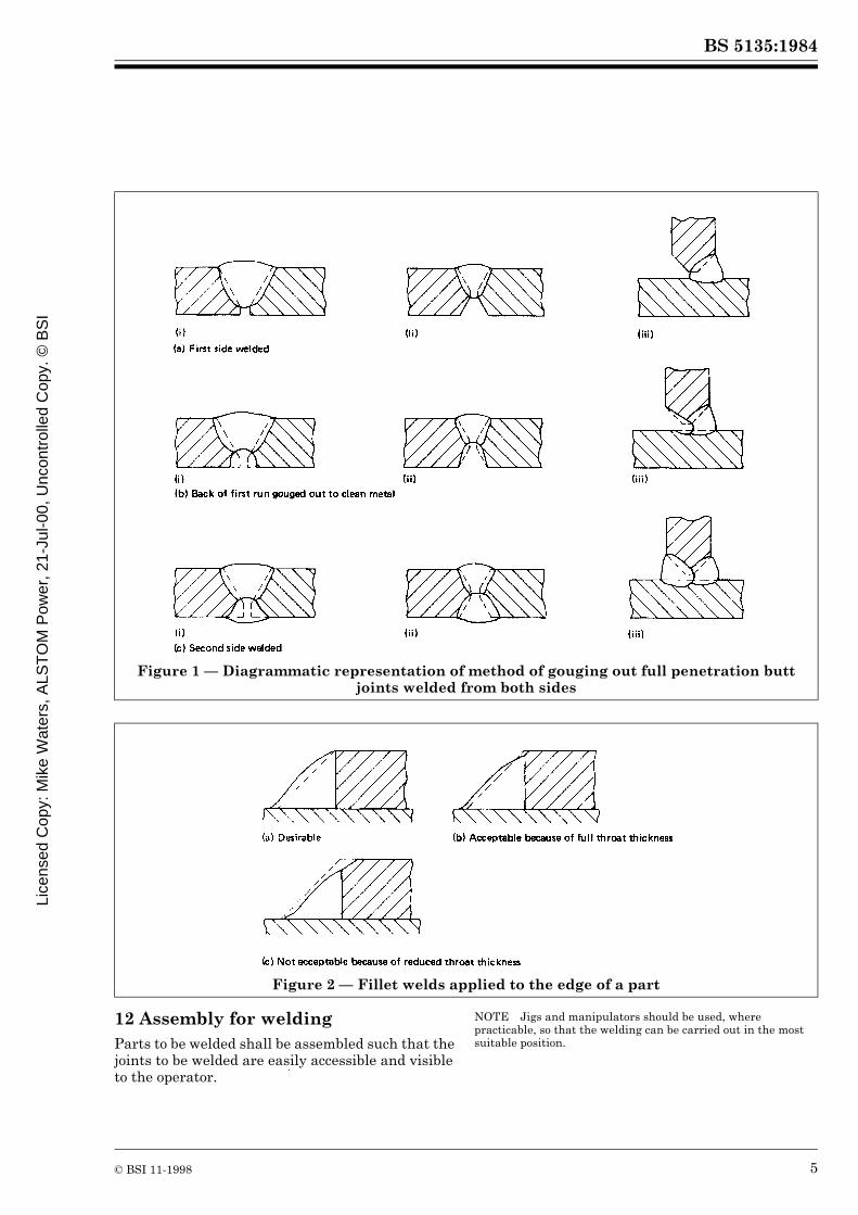
7.5.3 Where temporary or permanent backing material is employed, the joint shall be arranged in such a way as to ensure that complete fusion of the parts to be joined is readily obtained.7.6 Back gouging. In all full penetration butt welds, where these are to be welded from both sides, certain welding procedures allow this to be done without back gouging, but where complete penetration cannot be achieved, the back of the first run shall be gouged out by suitable means to clean sound metal before welding is started on the gouged-out side (see Figure 1).
8 Fillet weld detailsA fillet weld, as deposited, shall be not less than the specified dimensions (see 3.1 c)) which shall be clearly indicated as throat thickness and/or leg length as appropriate, taking into account the use of deep penetration processes or partial preparations (see clause 14 and, for guidance, Appendix C).For concave fillet welds, the actual throat thickness shall be not less than 0.7 times the specified leg length (see 3.1 c)). For convex fillet welds, the actual throat thickness shall be not more than 0.9 times the actual leg length.Where the specified leg length (see 3.1 c)) of a fillet weld at the edge of a plate or section is such that the parent metal does not project beyond the weld, melting of the outer corner or corners, which reduces the throat thickness, shall not be allowed (see Figure 2).NOTE Guidance on the design of fillet welds is given in A.2.
9 Welds in slotsBecause of the risk of cracking, slots shall not be filled with weld metal unless required by the application standard. Slots that are required to be filled with weld metal shall only be filled after the fillet weld has been inspected and approved.
10 Preparation of joint faces10.1 If preparation or cutting of the material is necessary, this shall be done by shearing, chipping, grinding, machining, thermal cutting, thermal gouging or an alternative method agreed in accordance with 10.2. When shearing is used, the effect of work hardening shall be taken into account and precautions shall be taken to ensure that there is no cracking of the edges.In the cases where the cut edge is not a fusion face, the effect of embrittlement from shearing, thermal cutting or thermal gouging shall not be to the detriment of the performance of the fabrication.NOTE Local hardening can be reduced by suitable thermal treatment or removed by mechanical means. The removal of 1 mm to 2 mm from a cut face normally eliminates the layer of hardness. When using thermal cutting, local hardening can be reduced by a reduction in normal cutting speed or by preheating before cutting. The steel supplier should be consulted for recommendations on achieving a reduction in hardness.
10.2 Methods for preparation or cutting of the material other than by shearing, chipping, grinding, machining, thermal cutting or thermal gouging (as referred to in 10.1) shall only be used by agreement between the contracting parties.
11 Fusion faces11.1 The preparation of fusion faces, angle of bevel, root radius and root face shall be such that the limits of accuracy required by the appropriate application standard can be achieved.NOTE When no appropriate application standard exists, it is recommended that, for manual welding, the tolerances on limits of gap and root face should be ± 1 mm on the specified dimensions (see 3.1 c)) for material up to and including 12 mm thick and ± 2 mm for material over 12 mm thick. The tolerance on the included angle between the fusion faces of a V preparation is recommended to be ± 5° and for U and J preparations + 10°, – 0°. For an automatic or mechanized process, closer limits are necessary which depend on the characteristics of the process.
11.2 Fusion faces and adjacent surfaces shall be free from cracks, notches or other irregularities which would interfere with the deposition of the weld or be the cause of defects. Any repair to fusion faces shall be carried out in accordance with the requirements of this standard.11.3 Fusion faces and the surrounding surfaces shall be free from heavy scale, moisture, oil, paint or any other substance which might affect the quality of the weld or impede the progress of welding.NOTE This is particularly important when a hydrogen-controlled welding process is used. Certain proprietary protective coatings are specially formulated with the intention that they should not interfere with welding. The use of such coatings is not excluded by the requirements of this clause but, if so required by the purchaser, the contractor should demonstrate their acceptability by means of specimen welds (see BS 6084).
Licensed Copy: M
ike Waters, A
LST
OM
Pow
er, 21-Jul-00, Uncontrolled C
opy. © B
SI
BS 5135:1984
© BSI 11-1998 5
12 Assembly for weldingParts to be welded shall be assembled such that the joints to be welded are easily accessible and visible to the operator.
NOTE Jigs and manipulators should be used, where practicable, so that the welding can be carried out in the most suitable position.
Figure 1 — Diagrammatic representation of method of gouging out full penetration butt joints welded from both sides
Figure 2 — Fillet welds applied to the edge of a part
Lice
nsed
Cop
y: M
ike
Wat
ers,
ALS
TO
M P
ower
, 21-
Jul-0
0, U
ncon
trol
led
Cop
y. ©
BS
I
BS 5135:1984
6 © BSI 11-1998
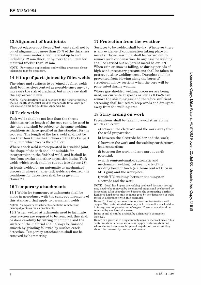
13 Alignment of butt jointsThe root edges or root faces of butt joints shall not be out of alignment by more than 25 % of the thickness of the thinner material for material up to and including 12 mm thick, or by more than 3 mm for material thicker than 12 mm.NOTE For certain applications and welding processes, closer tolerances may be necessary.
14 Fit-up of parts joined by fillet weldsThe edges and surfaces to be joined by fillet welds shall be in as close contact as possible since any gap increases the risk of cracking, but in no case shall the gap exceed 3 mm.NOTE Consideration should be given to the need to increase the leg length of the fillet weld to compensate for a large gap (see clause 8 and, for guidance, Appendix E).
15 Tack weldsTack welds shall be not less than the throat thickness or leg length of the root run to be used in the joint and shall be subject to the same welding conditions as those specified in this standard for the root run. The length of the tack weld shall not be less than four times the thickness of the thicker part or 50 mm whichever is the smaller.Where a tack weld is incorporated in a welded joint, the shape of the tack shall be suitable for incorporation in the finished weld, and it shall be free from cracks and other deposition faults. Tack welds which crack shall be cut out (see clause 28).In joints welded by an automatic or mechanized process or where smaller tack welds are desired, the conditions for deposition shall be as given in clause 21.
16 Temporary attachments16.1 Welds for temporary attachments shall be made in accordance with the same requirements of this standard that apply to permanent welds.NOTE Temporary attachments should be remote from principal joints as far as practicable.
16.2 When welded attachments used to facilitate construction are required to be removed, this shall be done carefully by cutting or chipping and the surface of the material shall always be finished smooth by grinding followed by surface crack detection. Temporary attachments shall not be removed by hammering.
17 Protection from the weatherSurfaces to be welded shall be dry. Whenever there is any evidence of condensation taking place on metal surfaces, warming shall be carried out to remove such condensation. In any case no welding shall be carried out on parent metal below 0 °C. When rain or snow is falling, or during periods of high wind, necessary precautions shall be taken to protect outdoor welding areas. Draughts shall be prevented from blowing along the bores of structural hollow sections when the bore will be penetrated during welding.Where gas-shielded welding processes are being used, air currents at speeds as low as 8 km/h can remove the shielding gas, and therefore sufficient screening shall be used to keep winds and draughts away from the welding area.
18 Stray arcing on workPrecautions shall be taken to avoid stray arcing which can occur:
a) between the electrode and the work away from the weld preparation;b) between the electrode holder and the work;c) between the work and the welding earth return lead connection;d) between the work and any part at earth potential;e) with semi-automatic, automatic and mechanized welding, between parts of the welding head or torch (e.g. loose contact tube in MIG gun) and the workpiece;f) with TIG welding, between the tungsten electrode and the work.
NOTE Local hard spots or cracking produced by stray arcing may need to be removed by mechanical means and be checked by inspection, after consultation between the contracting parties. Removed hard spots may be made good by the deposition of weld metal in accordance with this standard.Items b), c) and e) can result in localized contamination with copper. The contaminated area may be brittle and/or cracked due to intergranular penetration of copper. These areas should be removed by mechanical means.Items c) and d) can be avoided by a firm earth connection (see 6.2).Item f) can give rise to tungsten inclusions in the workpiece. This contamination is not so serious as copper contamination but where the inclusions are large and angular or numerous they should be removed by mechanical means.
Licensed Copy: M
ike Waters, A
LST
OM
Pow
er, 21-Jul-00, Uncontrolled C
opy. © B
SI

BS 5135:1984
© BSI 11-1998 7
19 Inter-run cleaningWhere a process generates a slag to protect the weld metal, e.g. manual metal-arc and submerged arc welding, this slag shall be removed from each run of weld metal before a further run is superimposed, particular attention being paid to the junctions between the weld metal and the fusion faces. Visible defects such as cracks, cavities and other deposition faults shall be removed before the deposition of further weld metal.
20 Details of welding procedureWhen written welding procedures are required by the purchaser, they shall include such of the following items as are relevant.
a) Welding process or processes when more than one is used in making a complete joint.b) Parent metal specification, thickness and other relevant dimensions.c) Whether shop or site welding.d) Cleaning, degreasing, etc.e) Classification, type and size of electrodes and other consumables.f) For manual welding, the size of electrode, welding current and length of run per electrode or fillet weld leg length and number of runs. For semi-automatic, automatic and mechanized welding, the size of electrode, welding current, arc voltage, speed of travel, wire feed speed, electrode extension or fillet weld leg length and number of runs and rate of flow of gas and/or consumption of other process materials, as appropriate. When applicable, the temperature and time adopted for drying/baking of welding consumables before use.g) Sketch showing edge preparation, fit-up and approximate number and arrangement of runs in multi-run welds.h) Jigging or tacking, backing, etc.i) Welding positions.j) Welding sequence.k) Minimum preheating temperature and interpass temperature range.l) Back gouging.m) Post-weld heat treatment.n) Any other relevant information (see Appendix D for guidance on fracture toughness of heat-affected zone and weld metal).
Welders shall be provided with sufficient information to enable the welding procedure to be carried out satisfactorily.
21 Welding procedures to avoid cracking21.1 General. In determining welding procedures consideration shall be given to the avoidance of the following:
a) hydrogen induced delayed cold cracking (see 21.2 and, for guidance, Appendix E);b) solidification cracking (for guidance see Appendix F);c) lamellar tearing (for guidance see Appendix G).
21.2 Procedures for avoiding hydrogen cracking
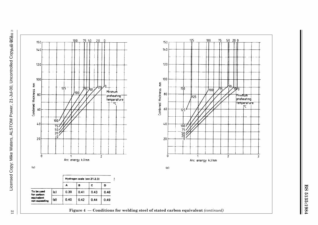
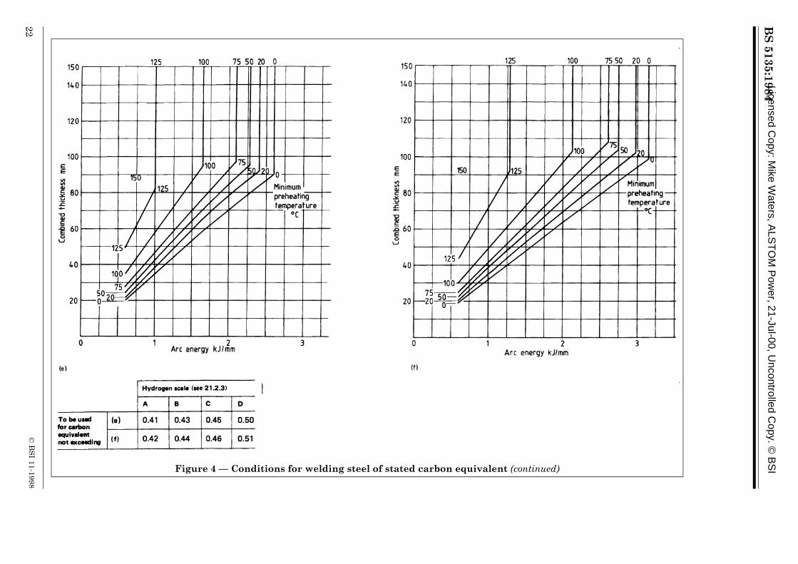
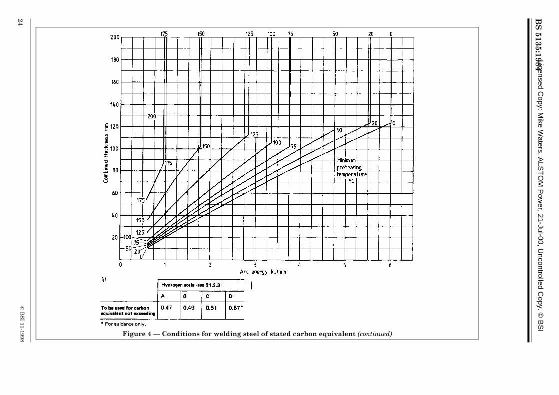
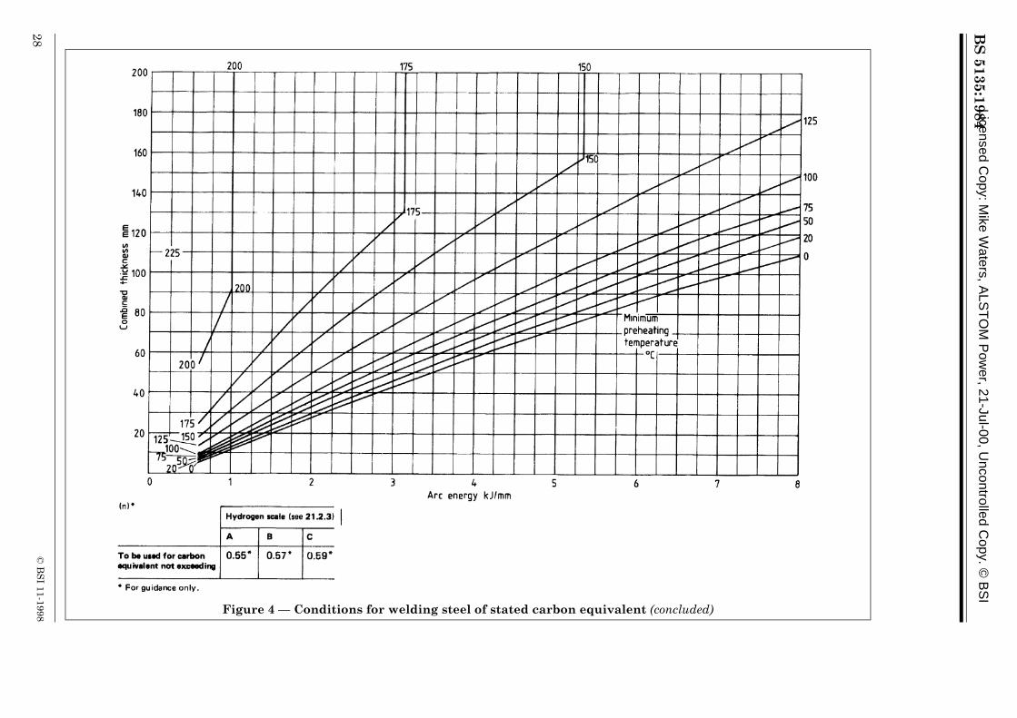
21.2.1 Introduction. Welding conditions for avoiding hydrogen cracking in carbon manganese steels have been drawn up in graphical form in Figure 4 for the normal range of compositions, expressed as carbon equivalent, covered by this standard and these conditions shall be followed whenever practicable. (See also 21.2.7.)NOTE The conditions have been drawn up to take account of differences in behaviour between different steels of the same carbon equivalent (making allowances for scatter in hardenability) and of normal variations between ladle and product analysis. They are valid for the avoidance of both heat-affected zone and weld metal cracking in the majority of welding situations. In some cases, the procedures determined in accordance with this clause may not be adequate to avoid hydrogen cracking and guidance on situations which may require more stringent procedures to avoid hydrogen cracking is given in Appendix E together with recommendations for these procedures.
21.2.2 Carbon equivalent values. The carbon equivalent values in Table 2 provide a good basis for the derivation of a welding procedure when using a steel complying with BS 4360. Where mill sheets indicate a higher carbon equivalent than Table 2 they shall form the basis for the procedure.NOTE Where mill sheets are available which show a lower carbon equivalent they may be used as a basis for a less stringent procedure (but see E.3).
If, of the elements in the formula in clause 4 for calculating carbon equivalent, only carbon and manganese are stated on the mill sheet, then 0.03 shall be added to the calculated value to allow for residual elements. Where steels of different carbon equivalent or grade are being joined, the higher carbon equivalent value shall be used.21.2.3 Hydrogen scales. The hydrogen scale to be used for any arc welding process depends principally on the weld diffusible hydrogen content and shall be as given in Table 1. The value used shall be that stated by the consumable manufacturer in accordance with the relevant standard where it exists (or as independently determined) in conjunction with a specified condition of supply and treatment.
Lice
nsed
Cop
y: M
ike
Wat
ers,
ALS
TO
M P
ower
, 21-
Jul-0
0, U
ncon
trol
led
Cop
y. ©
BS
I

BS 5135:1984
8 © BSI 11-1998
NOTE Guidance on the use of hydrogen scales for various processes is given in E.2.
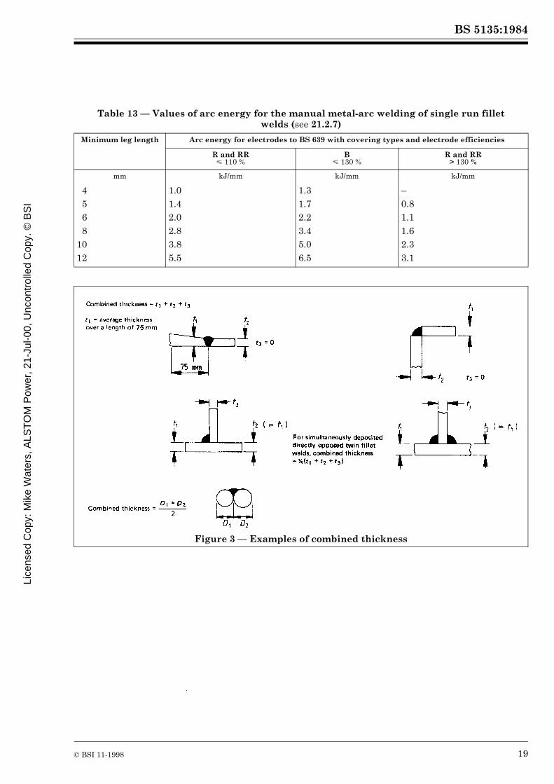
21.2.4 Preheating. The preheating temperature is the temperature of the parent metal immediately before welding commences, the same value frequently being used as the minimum interpass temperature for multi-run welds. Multi-run welds may have a lower permitted interpass temperature than the preheat temperature where subsequent runs are larger than the root run and in these cases the interpass temperature shall be determined from Figure 4 for the larger run.Where preheating is applied local to the joint preparation, the required temperature shall exist in the parent metal for a distance of at least 75 mm in any direction from the joint preparation. Where practicable, the temperature shall be measured on the face opposite to that being heated. Otherwise, the temperature shall be confirmed on the heated face at a time after removal of the heat source, related to parent metal thickness to allow for temperature equalization. Where fixed permanent heaters are in use and there is no access to the reverse face for temperature measurement, readings shall be taken on the exposed parent metal surface immediately adjacent to the weld preparation.NOTE The time allowed for temperature equalization should be of the order of 2 min for each 25 mm of parent metal thickness.
21.2.5 Combined thickness. Combined thickness shall be determined as the sum of the parent metal thicknesses averaged over a distance of 75 mm from the weld line (see Figure 3).NOTE If the thickness increases greatly just beyond 75 mm from the weld line, it may be necessary to use a higher combined thickness value.
21.2.6 Arc energy. Arc energy values (in kJ/mm) for use with Figure 4 shall be calculated as follows, with an appropriate factor applied for processes other than manual metal-arc welding with covered electrodes:
where
NOTE For guidance in using other welding processes, the arc energy values calculated from this formula should be divided by the following factors to give the values to be used in Figure 4:
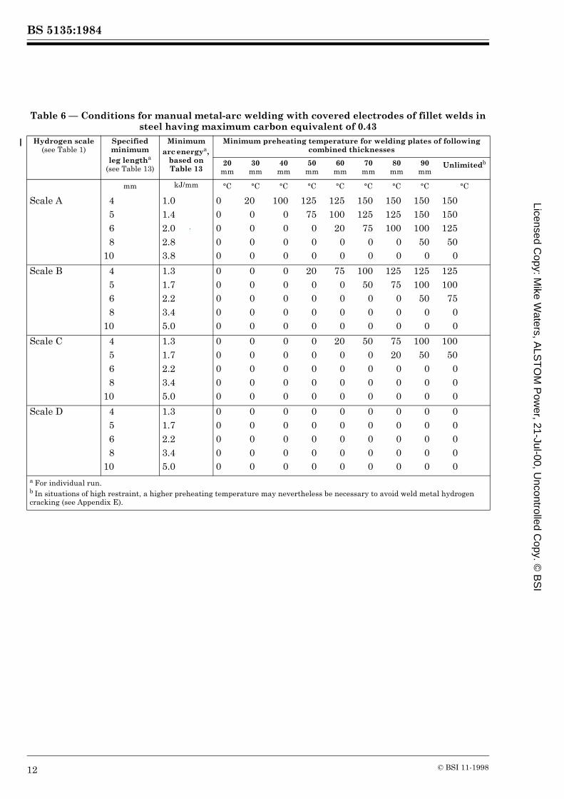
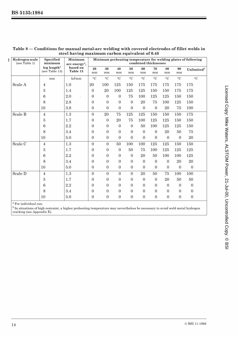
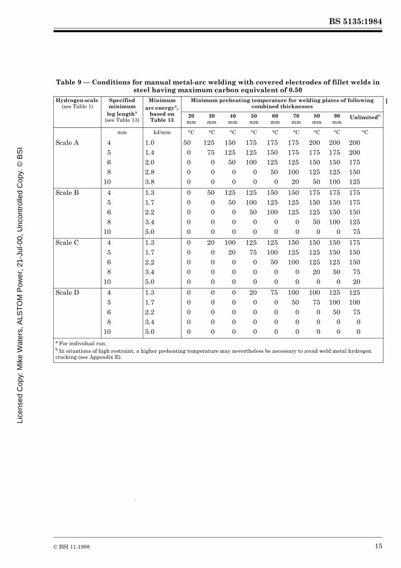
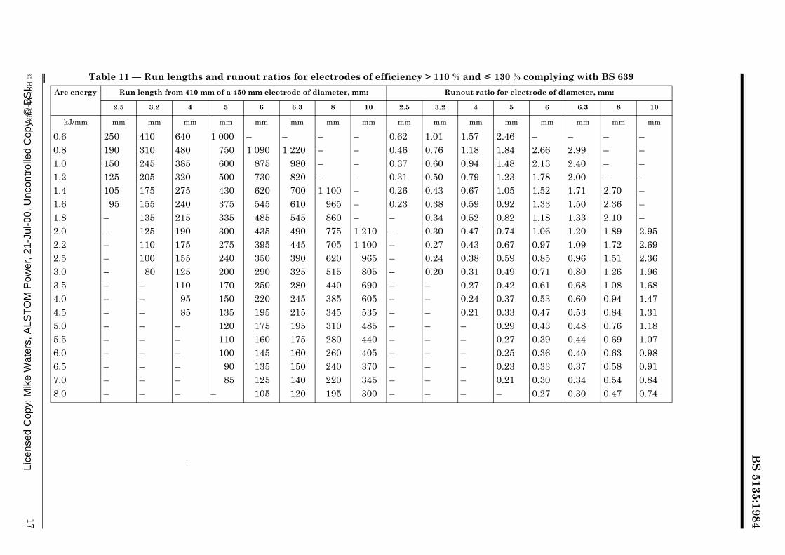
21.2.7 Simplified conditions for manual metal-arc welding. For the manual metal-arc welding of fillet welds the data obtainable from Figure 4 have been presented in tabular form for particular carbon equivalent values in Table 3 to Table 9.For manual metal-arc welding with covered electrodes, arc energy values are expressed in Table 10, Table 11 and Table 12 in terms of electrode size, weld run length and runout ratio.NOTE Where single run minimum leg length fillet welds are specified in the design, Table 13 may be used to obtain the approximate arc energy values for use in determining welding procedures from Table 3 to Table 9 or from Figure 4. These values are appropriate for the practical situation when a contractor is required to make single run fillet welds of a specified dimension related to the minimum leg length of the fillet welds and where in practice the second leg will be longer than the minimum, as for example in a horizontal-vertical fillet weld. In other cases arc energy should be controlled by control of electrode runout (Table 10, Table 11 and Table 12) or directly through welding parameters.
21.3 Alternative procedures. When alternative procedures are proposed the evidence shall include consideration of all the factors used in determining welding procedures as given in 21.2.NOTE Conditions which might justify modifications to normal welding procedures to avoid hydrogen cracking are mentioned in Appendix E.
Table 1 — Hydrogen scales
NOTE See E.3 for use of hydrogen levels below 2.5 mL/100 g of deposited metal.
V is the arc voltage (in V)
I is the welding current (in A)
w is the welding speed (in mm/s).
Submerged arc welding (single wire) : 0.8
MIG/MAG welding (solid, cored or self-shielded wire)
:1.0
TIG welding : 1.2
VIw------- 10 3–×
Diffusible hydrogen content Hydrogen scale
mL/100 g of deposited metal
Over Up to and including
1510
5–
–1510
5
ABCD
Licensed Copy: M
ike Waters, A
LST
OM
Pow
er, 21-Jul-00, Uncontrolled C
opy. © B
SI
BS 5135:1984
© BSI 11-1998 9
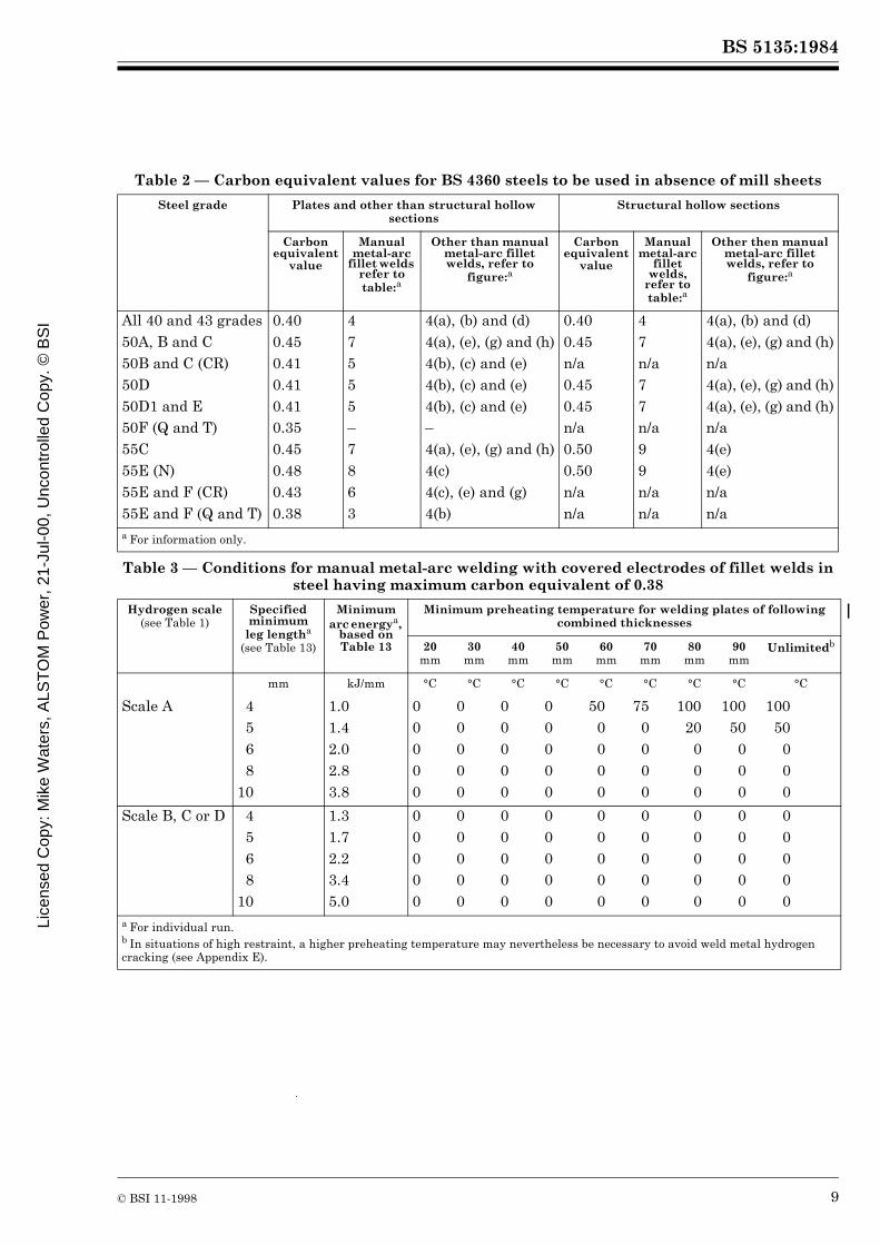
Table 2 — Carbon equivalent values for BS 4360 steels to be used in absence of mill sheets
Table 3 — Conditions for manual metal-arc welding with covered electrodes of fillet welds in steel having maximum carbon equivalent of 0.38
Steel grade Plates and other than structural hollow sections
Structural hollow sections
Carbon equivalent
value
Manual metal-arc
fillet welds refer to table:a
Other than manual metal-arc fillet welds, refer to
figure:a
Carbon equivalent
value
Manual metal-arc
fillet welds,
refer to table:a
Other then manual metal-arc fillet welds, refer to
figure:a
All 40 and 43 grades50A, B and C50B and C (CR)50D50D1 and E50F (Q and T)55C55E (N)55E and F (CR)55E and F (Q and T)
0.400.450.410.410.410.350.450.480.430.38
47555–7863
4(a), (b) and (d)4(a), (e), (g) and (h)4(b), (c) and (e)4(b), (c) and (e)4(b), (c) and (e)–4(a), (e), (g) and (h)4(c)4(c), (e) and (g)4(b)
0.400.45n/a0.450.45n/a0.500.50n/an/a
47n/a77n/a99n/an/a
4(a), (b) and (d)4(a), (e), (g) and (h)n/a4(a), (e), (g) and (h)4(a), (e), (g) and (h)n/a4(e)4(e)n/an/a
a For information only.
Hydrogen scale (see Table 1)
Specified minimum
leg lengtha (see Table 13)
Minimum arc energya,
based on Table 13
Minimum preheating temperature for welding plates of following combined thicknesses
20mm
30mm
40mm
50mm
60mm
70mm
80mm
90mm
Unlimitedb
mm kJ/mm °C °C °C °C °C °C °C °C °C
Scale A 4568
10
1.01.42.02.83.8
00000
00000
00000
00000
500000
750000
10020
000
10050
000
10050
000
Scale B, C or D 4568
10
1.31.72.23.45.0
00000
00000
00000
00000
00000
00000
00000
00000
00000
a For individual run.b In situations of high restraint, a higher preheating temperature may nevertheless be necessary to avoid weld metal hydrogen cracking (see Appendix E).
Lice
nsed
Cop
y: M
ike
Wat
ers,
ALS
TO
M P
ower
, 21-
Jul-0
0, U
ncon
trol
led
Cop
y. ©
BS
I

BS 5135:1984
10 © BSI 11-1998
Table 4 — Conditions for manual metal-arc welding with covered electrodes of fillet welds in steel having maximum carbon equivalent of 0.40
Hydrogen scale (see Table 1)
Specified minimum
leg lengtha (see Table 13)
Minimum arc energya,
based on Table 13
Minimum preheating temperature for welding plates of following combined thicknesses
20mm
30mm
40mm
50mm
60mm
70mm
80mm
90mm
Unlimitedb
mm kJ/mm °C °C °C °C °C °C °C °C °C
Scale A 4568
10
1.01.42.02.83.8
00000
00000
00000
500000
10020
000
12575
000
125100
2000
125100
5000
125100
5000
Scale B 4568
10
1.31.72.23.45.0
00000
00000
00000
00000
00000
200000
500000
500000
500000
Scale C or D 4568
10
1.31.72.23.45.0
00000
00000
00000
00000
00000
00000
00000
00000
00000
a For individual run.b In situations of high restraint, a higher preheating temperature may nevertheless be necessary to avoid weld metal hydrogen cracking (see Appendix E).
Licensed Copy: M
ike Waters, A
LST
OM
Pow
er, 21-Jul-00, Uncontrolled C
opy. © B
SI

BS 5135:1984
© BSI 11-1998 11
Table 5 — Conditions for manual metal-arc welding with covered electrodes of fillet welds in steel having maximum carbon equivalent of 0.41
Hydrogen scale (see Table 1)
Specified minimum
leg lengtha (see Table 13)
Minimum arc energya,
based on Table 13
Minimum preheating temperature for welding plates of following combined thicknesses
20mm
30mm
40mm
50mm
60mm
70mm
80mm
90mm
Unlimitedb
mm kJ/mm °C °C °C °C °C °C °C °C °C
Scale A 4568
10
1.01.42.02.83.8
00000
00000
500000
1000000
12550
000
125100
000
125100
5000
125125
7500
125125100
00
Scale B 4568
10
1.31.72.23.45.0
00000
00000
00000
00000
200000
500000
7520
000
10050
000
10050
000
Scale C 4568
10
1.31.72.23.45.0
00000
00000
00000
00000
00000
200000
500000
500000
500000
Scale D 4568
10
1.31.72.23.45.0
00000
00000
00000
00000
00000
00000
00000
00000
00000
a For individual run.b In situations of high restraint, a higher preheating temperature may nevertheless be necessary to avoid weld metal hydrogen cracking (see Appendix E).
Lice
nsed
Cop
y: M
ike
Wat
ers,
ALS
TO
M P
ower
, 21-
Jul-0
0, U
ncon
trol
led
Cop
y. ©
BS
I
BS 5135:1984
12 © BSI 11-1998
Table 6 — Conditions for manual metal-arc welding with covered electrodes of fillet welds in steel having maximum carbon equivalent of 0.43
Hydrogen scale (see Table 1)
Specified minimum
leg lengtha (see Table 13)
Minimum arc energya,
based on Table 13
Minimum preheating temperature for welding plates of following combined thicknesses
20mm
30mm
40mm
50mm
60mm
70mm
80mm
90mm
Unlimitedb
mm kJ/mm °C °C °C °C °C °C °C °C °C
Scale A 4568
10
1.01.42.02.83.8
00000
200000
1000000
12575
000
125100
2000
150125
7500
150125100
00
150150100
500
150150125
500
Scale B 4568
10
1.31.72.23.45.0
00000
00000
00000
200000
750000
10050
000
12575
000
125100
5000
125100
7500
Scale C 4568
10
1.31.72.23.45.0
00000
00000
00000
00000
200000
500000
7520
000
10050
000
10050
000
Scale D 4568
10
1.31.72.23.45.0
00000
00000
00000
00000
00000
00000
00000
00000
00000
a For individual run.b In situations of high restraint, a higher preheating temperature may nevertheless be necessary to avoid weld metal hydrogen cracking (see Appendix E).
Licensed Copy: M
ike Waters, A
LST
OM
Pow
er, 21-Jul-00, Uncontrolled C
opy. © B
SI

BS 5135:1984
© BSI 11-1998 13
Table 7 — Conditions for manual metal-arc welding with covered electrodes of fillet welds in steel having maximum carbon equivalent of 0.45
Hydrogen scale (see Table 1)
Specified minimum
leg lengtha (see Table 13)
Minimum arc energya,
based on Table 13
Minimum preheating temperature for welding plates of following combined thicknesses
20mm
30mm
40mm
50mm
60mm
70mm
80mm
90mm
Unlimitedb
mm kJ/mm °C °C °C °C °C °C °C °C °C
Scale A 4568
10
1.01.42.02.83.8
00000
750000
12550
000
125100
000
150125
7500
150125100
00
175150125
500
175150125100
0
175150150125
0
Scale B 4568
10
1.31.72.23.45.0
00000
00000
200000
750000
10075
000
125100
2000
125125
7500
150125100
00
150125125
00
Scale C 4568
10
1.31.72.23.45.0
00000
00000
00000
200000
750000
10050
000
1257520
00
125100
5000
125100
7500
Scale D 4568
10
1.31.72.23.45.0
00000
00000
00000
00000
00000
00000
00000
00000
00000
a For individual run.b In situations of high restraint, a higher preheating temperature may nevertheless be necessary to avoid weld metal hydrogen cracking (see Appendix E).
Lice
nsed
Cop
y: M
ike
Wat
ers,
ALS
TO
M P
ower
, 21-
Jul-0
0, U
ncon
trol
led
Cop
y. ©
BS
I
BS 5135:1984
14 © BSI 11-1998
Table 8 — Conditions for manual metal-arc welding with covered electrodes of fillet welds in steel having maximum carbon equivalent of 0.48
Hydrogen scale (see Table 1)
Specified minimum
leg lengtha (see Table 13)
Minimum arc energya,
based on Table 13
Minimum preheating temperature for welding plates of following combined thicknesses
20mm
30mm
40mm
50mm
60mm
70mm
80mm
90mm
Unlimitedb
mm kJ/mm °C °C °C °C °C °C °C °C °C
Scale A 4568
10
1.01.42.02.83.8
200000
10020
000
125100
000
150125
7500
175125100
200
175150125
750
175150125100
20
175175150125
75
175175150150100
Scale B 4568
10
1.31.72.23.45.0
00000
200000
7520
000
12575
000
125100
5000
150125100
00
150125125
200
150150125
500
175150150
7520
Scale C 4568
10
1.31.72.23.45.0
00000
00000
500000
10050
000
1007520
00
125100
5000
125125100
00
150125100
200
150125125
200
Scale D 4568
10
1.31.72.23.45.0
00000
00000
00000
00000
200000
500000
7520
000
10050
000
10050
000
a For individual run.b In situations of high restraint, a higher preheating temperature may nevertheless be necessary to avoid weld metal hydrogen cracking (see Appendix E).
Licensed Copy: M
ike Waters, A
LST
OM
Pow
er, 21-Jul-00, Uncontrolled C
opy. © B
SI
BS 5135:1984
© BSI 11-1998 15
Table 9 — Conditions for manual metal-arc welding with covered electrodes of fillet welds in steel having maximum carbon equivalent of 0.50
Hydrogen scale (see Table 1)
Specified minimum
leg lengtha (see Table 13)
Minimum arc energya,
based on Table 13
Minimum preheating temperature for welding plates of following combined thicknesses
20mm
30mm
40mm
50mm
60mm
70mm
80mm
90mm
Unlimitedb
mm kJ/mm °C °C °C °C °C °C °C °C °C
Scale A 4568
10
1.01.42.02.83.8
500000
12575
000
150125
5000
175125100
00
175150125
500
175175125100
20
200175150125
50
200175150125100
200200175150125
Scale B 4568
10
1.31.72.23.45.0
00000
500000
12550
000
125100
5000
150125100
00
150125125
00
175150125
500
175150150100
0
175175150125
75
Scale C 4568
10
1.31.72.23.45.0
00000
200000
10020
000
12575
000
125100
5000
150125100
00
150125125
200
150150125
500
175150150
7520
Scale D 4568
10
1.31.72.23.45.0
00000
00000
00000
200000
750000
10050
000
10075
000
125100
5000
125100
7500
a For individual run.b In situations of high restraint, a higher preheating temperature may nevertheless be necessary to avoid weld metal hydrogen cracking (see Appendix E).
Lice
nsed
Cop
y: M
ike
Wat
ers,
ALS
TO
M P
ower
, 21-
Jul-0
0, U
ncon
trol
led
Cop
y. ©
BS
I

BS
5135:1984
16©
BS
I 11-1998
Table 10 — Run lengths and runout ratios for electrodes of efficiency << 110 % complying with BS 639
Arc energy Run length from 410 mm of a 450 mm electrode of diameter, mm: Runout ratio for electrode of diameter, mm:
2.5 3.2 4 5 6 6.3 8 10 2.5 3.2 4 5 6 6.3 8 10
kJ/mm mm mm mm mm mm mm mm mm mm mm mm mm mm mm mm mm
0.60.81.01.21.41.61.82.02.22.53.03.54.04.55.05.56.06.57.08.0
220165130110
95–––––––––––––––
355270215180150135120105
9585
––––––––––
550415330275235205185165150130110
9580
–––––––
870650520435370325290260235205175150130115105
9585
–––
–940750625535470415375340300250215185165150135125115105
95
–1 040
830690590520460415375330275235205185165150135125115105
–––1 110
955840745670610535445380335295265245225205190165
––––––1 1601 040
950835695595520465415380350320300260
0.530.400.320.270.23–––––––––––––––
0.870.650.520.440.370.330.290.260.240.21––––––––––
1.351.010.810.670.580.500.450.400.370.320.270.230.20–––––––
2.121.591.271.060.910.790.710.640.580.510.420.360.320.280.250.230.21–––
–2.401.841.531.311.141.020.920.830.730.610.520.460.410.370.330.310.280.260.23
–2.532.021.681.441.261.121.010.920.810.670.580.500.450.400.370.340.310.290.25
–––2.722.342.051.821.641.491.311.090.940.820.730.650.590.540.500.470.41
––––––2.832.552.312.041.701.461.281.131.020.930.850.780.730.64
Licensed Copy: M
ike Waters, A
LST
OM
Pow
er, 21-Jul-00, Uncontrolled C
opy. © B
SI
BS
5135:1984
© B
SI 11-1998
17
Table 11 — Run lengths and runout ratios for electrodes of efficiency > 110 % and << 130 % complying with BS 639
Arc energy Run length from 410 mm of a 450 mm electrode of diameter, mm: Runout ratio for electrode of diameter, mm:
2.5 3.2 4 5 6 6.3 8 10 2.5 3.2 4 5 6 6.3 8 10
kJ/mm mm mm mm mm mm mm mm mm mm mm mm mm mm mm mm mm
0.60.81.01.21.41.61.82.02.22.53.03.54.04.55.05.56.06.57.08.0
250190150125105
95––––––––––––––
410310245205175155135125110100
80–––––––––
640480385320275240215 190175155125110
9585
––––––
1 000750600500430375335300275240200170150135120110100
9085
–
–1 090
875730620545485435395350290250220195175160145135125105
–1 220
980820700610545490445390325280245215195175160150140120
––––1 100
965860775705620515440385345310280260240220195
–––––––1 2101 100
965805690605535485440405370345300
0.620.460.370.310.260.23––––––––––––––
1.010.760.600.500.430.380.340.300.270.240.20–––––––––
1.571.180.940.790.670.590.520.470.430.380.310.270.240.21––––––
2.461.841.481.231.050.920.820.740.670.590.490.420.370.330.290.270.250.230.21–
–2.662.131.781.521.331.181.060.970.850.710.610.530.470.430.390.360.330.300.27
–2.992.402.001.711.501.331.201.090.960.800.680.600.530.480.440.400.370.340.30
––––2.702.362.101.891.721.511.261.080.940.840.760.690.630.580.540.47
–––––––2.952.692.361.961.681.471.311.181.070.980.910.840.74
Lice
nsed
Cop
y: M
ike
Wat
ers,
ALS
TO
M P
ower
, 21-
Jul-0
0, U
ncon
trol
led
Cop
y. ©
BS
I

BS
5135:1984
18©
BS
I 11-1998
Table 12 — Run lengths and runout ratios for electrodes of efficiency > 130 % complying with BS 639
Arc energy Run length from 410 mm of a 450 mm electrode of diameter, mm: Runout ratio for electrode of diameter, mm:
2.5 3.2 4 5 6 6.3 8 10 2.5 3.2 4 5 6 6.3 8 10
kJ/mm mm mm mm mm mm mm mm mm mm mm mm mm mm mm mm mm
0.60.81.01.21.41.61.82.02.22.53.03.54.04.55.05.56.06.57.08.0
325240195160135120105
9585
–––––––––––
530395315265225200175160145125105
90––––––––
830620495415355310275250225200165140125110100
9080
–––
–975780650555485430390355310260220195170155140130120110
95
––1 120
935800700620560510450370320280250225205185170160140
––1 2301 030
880770685620560495410350310275245225205190175155
–––––1 2401 1001 000
905800665570500445400360330305285250
–––––––––1 2401 030
890780690620565520480445390
0.790.590.480.400.340.300.260.240.22–––––––––––
1.300.970.780.650.560.490.430.390.350.310.260.22––––––––
2.021.521.221.010.870.760.670.610.550.490.400.350.300.270.240.220.20–––
–2.381.901.581.361.181.050.950.860.760.630.540.480.420.380.350.320.290.270.24
––2.742.281.951.711.521.361.241.100.910.780.680.610.550.500.460.420.390.34
––3.012.512.151.881.671.511.371.201.000.860.750.670.600.550.500.460.430.38
–––––3.042.712.432.211.961.621.391.221.080.970.880.810.750.700.61
–––––––––3.042.532.171.901.691.521.381.261.171.080.95
Licensed Copy: M
ike Waters, A
LST
OM
Pow
er, 21-Jul-00, Uncontrolled C
opy. © B
SI
BS 5135:1984
© BSI 11-1998 19
Table 13 — Values of arc energy for the manual metal-arc welding of single run fillet welds (see 21.2.7)
Minimum leg length Arc energy for electrodes to BS 639 with covering types and electrode efficiencies
R and RR < 110 %
B< 130 %
R and RR> 130 %
mm kJ/mm kJ/mm kJ/mm
4568
1012
1.01.42.02.83.85.5
1.31.72.23.45.06.5
–0.81.11.62.33.1
Figure 3 — Examples of combined thickness
Lice
nsed
Cop
y: M
ike
Wat
ers,
ALS
TO
M P
ower
, 21-
Jul-0
0, U
ncon
trol
led
Cop
y. ©
BS
I

BS
5135:1984
20©
BS
I 11-1998
Figure 4 — Conditions for welding steel of stated carbon equivalent
Licensed Copy: M
ike Waters, A
LST
OM
Pow
er, 21-Jul-00, Uncontrolled C
opy. © B
SI
BS
5135:1984
© B
SI 11-1998
21 Figure 4 — Conditions for welding steel of stated carbon equivalent (continued)
Lice
nsed
Cop
y: M
ike
Wat
ers,
ALS
TO
M P
ower
, 21-
Jul-0
0, U
ncon
trol
led
Cop
y. ©
BS
I
BS
5135:1984
22©
BS
I 11-1998
Figure 4 — Conditions for welding steel of stated carbon equivalent (continued)
Licensed Copy: M
ike Waters, A
LST
OM
Pow
er, 21-Jul-00, Uncontrolled C
opy. © B
SI

BS
5135:1984
© B
SI 11-1998
23 Figure 4 — Conditions for welding steel of stated carbon equivalent (continued)
Lice
nsed
Cop
y: M
ike
Wat
ers,
ALS
TO
M P
ower
, 21-
Jul-0
0, U
ncon
trol
led
Cop
y. ©
BS
I
BS
5135:1984
24©
BS
I 11-1998 Figure 4 — Conditions for welding steel of stated carbon equivalent (continued)
Licensed Copy: M
ike Waters, A
LST
OM
Pow
er, 21-Jul-00, Uncontrolled C
opy. © B
SI

BS
5135:1984
© B
SI 11-1998
25 Figure 4 — Conditions for welding steel of stated carbon equivalent (continued)
Lice
nsed
Cop
y: M
ike
Wat
ers,
ALS
TO
M P
ower
, 21-
Jul-0
0, U
ncon
trol
led
Cop
y. ©
BS
I

BS
5135:1984
26©
BS
I 11-1998
Figure 4 — Conditions for welding steel of stated carbon equivalent (continued)
Licensed Copy: M
ike Waters, A
LST
OM
Pow
er, 21-Jul-00, Uncontrolled C
opy. © B
SI

BS
5135:1984
© B
SI 11-1998
27 Figure 4 — Conditions for welding steel of stated carbon equivalent (continued)
Lice
nsed
Cop
y: M
ike
Wat
ers,
ALS
TO
M P
ower
, 21-
Jul-0
0, U
ncon
trol
led
Cop
y. ©
BS
I
BS
5135:1984
28©
BS
I 11-1998 Figure 4 — Conditions for welding steel of stated carbon equivalent (concluded)
Licensed Copy: M
ike Waters, A
LST
OM
Pow
er, 21-Jul-00, Uncontrolled C
opy. © B
SI
BS 5135:1984
© BSI 11-1998 29
22 Approval and testing of welding proceduresWhen written welding procedures are required (see clause 20) and if required by the purchaser, the contractor shall satisfy the purchaser that he can make satisfactory welds with the welding procedures to be used on the contract. If so required by the purchaser, the contractor shall carry out procedure tests in accordance with BS 4870-1.
23 Approval and testing of weldersThe contractor shall satisfy the purchaser that the welders are suitable for the work upon which they will be employed. For this purpose the welders shall have satisfied the relevant requirements of BS 4872-1. If the welders will be working to approved welding procedures, they shall have satisfied the relevant requirements of BS 4871-1.
24 IdentificationWhen specified by the purchaser, adequate means of identification, either by an identification mark or other record, shall be provided to enable each weld to be traced to the welder(s) by whom it was made.NOTE Attention is drawn to the danger of hard stamping in highly stressed areas and the designer should give guidance as to the location of such marks. Indentations used for marking in radio-graphic examination come into the same category.
25 PeeningPeening of welds shall be carried out only by agreement between the contracting parties.
26 Inspection and testing26.1 The method and extent of inspection and testing shall be in accordance with the relevant application standard where it exists.26.2 If no application standard exists, the method and extent of inspection shall be agreed between the contracting parties (see 3.2).NOTE Because of the risk of delayed cracking, a period of at least 48 h is recommended before inspection is made of as-welded fabrications. Whatever period is used it should be stated in the inspection records.
26.3 Welds which are to be inspected and approved shall not be painted or otherwise obscured until they have been accepted.
27 Quality of welds27.1 Welded joints shall be free from defects that would impair the service performance of the construction. Such acceptance requirements, covering both surface and sub-surface defects, shall be in accordance with the application standard where it exists.27.2 If no application standard exists, acceptance requirements shall be agreed between the contracting parties (see 3.2).NOTE When no application standard exists which specifies acceptance criteria, the guidance given in Appendix H may be used to facilitate agreement between the contracting parties on the requirements to be met.
28 Correction of faulty weldsWhere welds do not comply with the requirements of clause 27, the defective portions shall be removed, the weld repaired and then reinspected in accordance with this standard.NOTE If undercutting is blended out by grinding, care should be taken to ensure that the design thickness of the parent metal is not reduced. In exceptional circumstances, unacceptable undercutting may be made good by the deposition of additional weld metal in accordance with this standard.
29 Heat treatment29.1 When heat treatment of welds is required, this shall be done in accordance with the application standard where it exists.29.2 When heat treatment of welds is required but no application standard exists, the heat treatment details shall be agreed between the contracting parties taking account of the effect on the properties of the joint and fabrication.
Lice
nsed
Cop
y: M
ike
Wat
ers,
ALS
TO
M P
ower
, 21-
Jul-0
0, U
ncon
trol
led
Cop
y. ©
BS
I

BS 5135:1984
30 © BSI 11-1998
Appendix A Guidance on designNOTE 1 Typical application standards covering weld design aspects are BS 153-3B & BS 153-4, and BS 449-2.NOTE 2 Particular guidance on design to avoid lamellar tearing is given in Appendix G.A.1 Butt joints (see also Appendix B). Butt joints between parts of unequal cross section arranged in line will result in local increase in stress in addition to the stress concentration caused by the profile of the weld itself. If the centre planes of the two parts joined do not coincide, local bending also will be induced at the joint. If the stresses induced by these effects are unacceptable, then the parts should be shaped so as to reduce the stresses. Examples of plain and shaped parts are shown in Figure 5, where (a) and (b) are the more common types with (c) being a special configuration to facilitate non-destructive testing. The slope of the taper should be based on design requirements. If no such requirement is stated, it is recommended that the slope should not be steeper than 1 in 4.An incomplete penetration butt weld which is welded from one side only should not be subjected to a bending moment about the longitudinal axis of the weld which would cause the root of the weld to be in tension, unless this is allowed by the application standard.The use of incomplete penetration butt welds to resist repeating or alternating dynamic forces should be avoided where possible but, where they are used, the design stresses should be suitable for the loading conditions.Welded joints subjected to fluctuating loads should be designed so that the stresses satisfy the requirements of BS 5400-10.A.2 Fillet welds. The effective length of an open ended fillet weld should be taken as the overall length less twice the leg length, thereby discounting the contribution of the stop and start positions which are generally of reduced profile. In any case, the effective length should not be less than four times the leg length. Fillet welds terminating at the ends or sides of parts should be returned continuously around the corners for a distance of not less than twice the leg length of the weld unless access or the configuration render this impracticable. This procedure is particularly important for fillet welds on the tension side of parts carrying a bending load.In fillet welded joints carrying a compressive load, it should not be assumed that the parts joined are in contact under the joint. For critical applications the use of a partial or even a full penetration weld should be considered.
A single fillet weld should not be subjected to a bending moment about the longitudinal axis of the joint which would cause the root of the weld to be in tension.Where fillet welds are used in slots or holes through one or more of the parts being joined, the dimensions of the slot or hole should comply with the following limits in terms of the thickness of the part or parts in which the slot or hole is formed.
a) The width or diameter should be not less than three times the thickness or 25 mm, whichever is the greater.b) Corners at the enclosed ends of slots should be rounded with a radius of not less than 1.5 times the thickness or 12 mm, whichever is the greater.c) The distance between the edge of the part and the edge of the slot or hole, or between adjacent slots or holes, should be not less than twice the thickness and not less than 25 mm for holes.
Fillet welds connecting parts, the fusion faces of which form an angle of more than 120° or less than 60°, should not be relied upon to transmit calculated loads at the full working stresses unless permitted to do so by the application standard.The design throat thickness of a flat or convex fillet weld connecting parts, the fusion faces of which form an angle of between 60° and 120°, may be derived by multiplying the leg length by the appropriate factor as given in Table 14.Table 14 — Factors for deriving design throat
thickness of flat or convex fillet welds
Due account should be taken of fabrication, transport, and erection stresses particularly for those fillet welds which have been designed to carry only a light load during service.Compound welds, consisting of a butt weld plus a fillet weld, should be treated as a fillet weld for fatigue considerations. Welded joints subjected to fluctuating loads should be designed so that the stresses satisfy the requirements of BS 5400-10.
Angle between fusion faces Factor
degrees
60 to 9091 to 100
101 to 106107 to 113114 to 120
0.70.650.60.550.5
Licensed Copy: M
ike Waters, A
LST
OM
Pow
er, 21-Jul-00, Uncontrolled C
opy. © B
SI

BS 5135:1984
© BSI 11-1998 31
Appendix B Guidance on butt welds (for other than structural hollow sections)B.1 Introduction. The recommended dimensions of the preparations are intended primarily for manual welding in the flat position for general types of welded constructions. Since overhead and vertical welding require manipulation of the electrode, comparatively easy access to the root of the weld is desirable for welding in these positions. This is obtained by using a wider angle for the weld preparation, or sometimes by increasing the root gap. When using electrodes with a thick covering, some modification to the root details of the weld preparation may be necessary. The dimensions may be different for semi-automatic, automatic or mechanized welding.B.2 Suitable methods of making weld preparations. Single and double V and bevel preparations may be machined or machine flame cut. Single and double U and J preparations usually have to be machined. The choice of a machined or machine flame cut preparation should be at the option of the contractor except when specified by the purchaser or in the appropriate application standard.In assessing the merits of the two methods of preparation and the type of joint, the relative costs of machining, flame cutting and length of weld should be taken into account.
B.3 Selection of weld preparation to control distortion. U and J preparations as compared with V and bevel preparations serve to reduce distortion by virtue of the lesser amount of weld metal required. Likewise, double preparations are better than single preparations in that the weld metal can be deposited in alternate runs in each side of the joint. In the control of distortion, accuracy of preparation and fit-up of parts are important considerations, as well as a carefully planned and controlled welding procedure.B.4 Typical forms of weld preparation. Typical forms of weld preparation are shown in Table 15. In the case of square butt joints (a) and (b), the width of the gap depends mainly on the size and type of electrode and the gap should be chosen accordingly.The two joints (c) and (d) are probably the most common butt weld preparations used in general work. A root face without a gap usually facilitates assembly and minimizes contraction. The production of a sound weld, with or without gouging out of the back of the first run, is a function of the gap, root face and the type of electrode used. More reliable production of sound welds can be achieved by using back gouging.While the double V preparations (e) and (f) usually show a saving in weld metal, it is more difficult in these joints to ensure full fusion at the centre of the weld. If a root face is provided for assembly purposes and full fusion is a requirement, adequate gouging out of the back of the first run may be necessary.
Figure 5 — Butt joints of unequal cross section
Lice
nsed
Cop
y: M
ike
Wat
ers,
ALS
TO
M P
ower
, 21-
Jul-0
0, U
ncon
trol
led
Cop
y. ©
BS
I

BS 5135:1984
32 © BSI 11-1998
The single and double U preparations (g), (h) and (j) are designed to give easy access for the electrode and to ensure good arcing conditions particularly for the first run.
Single and double J preparations (k) and (l) and single and double bevel preparations (m) and (n) are used where only one joint member can be prepared. Preparations (m) and (n) are used for lesser thicknesses and where plate edges cannot be machined. To ensure weld soundness great care should be exercised, especially at the root of the double bevel butt weld.
Table 15 — Typical forms of butt weld preparation (other than structural hollow sections)Weld type Typical joint detail Dimensions and remarks
(a)Open square(without backing)Welded from both sides
Flat position:thickness T, 3 mm to 6 mm; gap G, 3 mm.
Horizontal/vertical or vertical position:thickness T, 3 mm to 5 mm; gap G, 3 mm.
See clause 11 for tolerances. See also clause 7(b)Open square(with backing)Welded from one side with backing which case it may be either temporary or permanent in which may be part of the structure or an integral part of one member
All positions.For flat position onlya:
Thickness Tmm
Gap G mm
3 to 55 to 88 to 16
68
10If this preparation is used for material over 16 mm thick the gap may be required to be increased.See clause 11 for tolerances. See also clause 7
(c) Single V(without backing)Welded from both sides or one side only
All positions.For flat position onlya:
gap G, 2 mm; angle a, 60°;thickness T, 5 mm to 12 mm:
root face R, 1 mm;thickness T, over 12 mm:
root face R, 2 mm.See clause 11 for tolerances. See also clause 7
(d) Single V(with backing)Welded from one side with backing which may be either temporary or permanent in which case it may be part of the structure or an integral part of one member
All positions:thickness T, over 10 mm.
For flat position onlya:root face R, 0;single root run:
gap G, 6 mm; angle a, 45°;double root run:
gap G, 10 mm; angle a, 20°.See clause 11 for tolerances. See also clause 7
(e)Double VWelded from both sides
All positions:thickness T, over 12 mm.
For flat position onlya:gap G, 3 mm;angle a, 60°;root face R, 2 mm.
See clause 11 for tolerances. See also clause 7.
Licensed Copy: M
ike Waters, A
LST
OM
Pow
er, 21-Jul-00, Uncontrolled C
opy. © B
SI

BS 5135:1984
© BSI 11-1998 33
Table 15 — Typical forms of butt weld preparation (other than structural hollow sections) Weld type Typical joint detail Dimensions and remarks
(f)Asymmetric double VWelded from both sides
All positions:thickness T, over 12 mm.
For flat position onlya:gap G, 3 mm;angle a, 60°; angle b, 60°;root face R, 2 mm.
See clause 11 for tolerances. See also clause 7.If the deeper V is welded first and full root penetration is required, the angle b may be increased to 90° to facilitate back gouging
(g) Single UWelded from both sides
All positions:thickness T, over 20 mm.
For flat position onlya:angle a, 20°;radius r, 5 mm;root face R, 5 mm.
See clause 11 for tolerances. See also clause 7
(h) Double UWelded from both sides
All positions:thickness T, over 40 mm.
For flat position onlya:angle a, 20°;radius r, 5 mm;root face R, 5 mm.
See clause 11 for tolerances. See also clause 7
(j) Asymmetric double UWelded from both sides
All positions:thickness T, over 30 mm.
For flat position onlya:land L, 6 mm;angle a, 20°;radius r, 5 mm;root face R, 5 mm.
See clause 11 for tolerances. See also clause 7
(k) Single JWelded from both sides
All positions:thickness T, over 20 mm.
For flat position onlya: land L, 5 mm;angle a, 20°;radius r, 5 mm;root face R, 5 mm.
See clause 11 for tolerances. See also clause 7
(l) Double JWelded from both sides
All positions:thickness T, over 40 mm.
For flat position onlya: land L, 5 mm;angle a, 20°;radius r, 5 mm;root face R, 5 mm.
See clause 11 for tolerances. See also clause 7
Lice
nsed
Cop
y: M
ike
Wat
ers,
ALS
TO
M P
ower
, 21-
Jul-0
0, U
ncon
trol
led
Cop
y. ©
BS
I

BS 5135:1984
34 © BSI 11-1998
Table 15 — Typical forms of butt weld preparation (other than structural hollow sections)
Appendix C Guidance on typical details for structural hollow sectionsTypical details for butt welds for structural hollow sections are given in Table 16. Branch connections for circular and rectangular structural hollow sections for butt and fillet welds are shown in Figure 6 to Figure 9.
Table 16 — Typical forms of butt weld preparation for structural hollow sections
Weld type Typical joint detail Dimensions and remarks
(m) Single bevelWelded from both sides
All positions.For flat position onlya:
gap G, 3 mm; angle a, 45°;thickness T, 5 mm to 12 mm:
root face R, 1 mm;thickness T, over 12 mm:
root face R, 2 mm.See clause 11 for tolerances. See also clause 7
(n) Double bevelWelded from both sides
All positions:thickness T, over 12 mm.
For flat position onlya:gap G, 3 mm;angle a, 45°;root face R, 2 mm.
See clause 11 for tolerances. See also clause 7
a The dimensions of the weld preparation may have to be modified for other processes and for welding in positions other than flat.
NOTE All preparations are for welding from one side only and in all positions.
Weld type Typical joint detail Dimensions
(a)Square(without backing)
Thickness T, up to 3 mm:gap G, 3 mm max.
(b)Square(with backing)
Thickness T, 3 mm:gap G, 3 mm min. 5 mm max.;thickness of backing t, 3 mm.
Thickness T, 5 mm:gap G, 5 mm min. 6 mm max.;thickness of backing t, 3 mm min. 5 mm max.
Thickness T, 6mm:gap G, 6 mm min. 8 mm max.;thickness of backing t, 3 mm min. 6 mm max.
(c)Single V(without backing)
Thickness T, up to 20 mm;gap G, 2 mm min. 3 mm max.;root face R, 1 mm min. 2.5 mm max.
(d)Single V(with backing)
Thickness T, up to 20 mm:gap G, 5 mm min. 8 mm max.;root face R, 2.5 mm max.;thickness of backing t, 3 mm min. 6 mm max.
Licensed Copy: M
ike Waters, A
LST
OM
Pow
er, 21-Jul-00, Uncontrolled C
opy. © B
SI

BS 5135:1984
© BSI 11-1998 35
Table 16 — Typical forms of butt weld preparation for structural hollow sections
Weld type Typical joint detail Dimensions
(e)Single Vflame cut preparation(with backing)
Thickness T, 20 mm to 30 mm:gap G, 8 mm min. 10 mm max.;root face R, 3 mm max.;thickness of backing t, 3 mm min. 10 mm max.
(f)Double angle V(with backing)
Thickness T, 20 mm and over:gap G, 8 mm min. 10 mm max.;root face R, 3 mm max.;thickness of backing t, 3 mm min. 10 mm max.
(g)Single bevel(without backing)
Thickness T, up to 20 mm:gap G, 2.5 mm min. 4 mm max.;root face R, 1 mm min. 3 mm max.
(h) Single bevel(with backing)
Thickness T, up to 20 mm:gap G, 5 mm min. 8 mm max.;root face R, 3 mm max.;thickness of backing t, 3 mm min. 6 mm max.
(J)Single bevelflame cut preparation (with backing)
Thickness T, 20 mm to 30 mm:gap G, 8 mm min. 10 mm max.;root face R, 3 mm max.;thickness of backing t, 3 mm min. 10 mm max.
(k)Double angle bevel(with backing)
Thickness T, 20 mm and over:gap G, 8 mm min. 10 mm max.;root face R, 3 mm max.;thickness of backing t, 3 mm min. 10 mm max.
Lice
nsed
Cop
y: M
ike
Wat
ers,
ALS
TO
M P
ower
, 21-
Jul-0
0, U
ncon
trol
led
Cop
y. ©
BS
I

BS 5135:1984
36 © BSI 11-1998
Figure 6 — Branch connections for circular structural hollow sections: butt welds (thickness up to 30 mm)
Licensed Copy: M
ike Waters, A
LST
OM
Pow
er, 21-Jul-00, Uncontrolled C
opy. © B
SI

BS 5135:1984
© BSI 11-1998 37
Figure 7 — Branch connections for circular structural hollow sections: fillet welds
Lice
nsed
Cop
y: M
ike
Wat
ers,
ALS
TO
M P
ower
, 21-
Jul-0
0, U
ncon
trol
led
Cop
y. ©
BS
I

BS 5135:1984
38 © BSI 11-1998
Figure 8 — Branch connections for rectangular structural hollow sections: butt welds
Licensed Copy: M
ike Waters, A
LST
OM
Pow
er, 21-Jul-00, Uncontrolled C
opy. © B
SI

BS 5135:1984
© BSI 11-1998 39
Figure 9 — Branch connections for rectangular structural hollow sections: fillet welds
Lice
nsed
Cop
y: M
ike
Wat
ers,
ALS
TO
M P
ower
, 21-
Jul-0
0, U
ncon
trol
led
Cop
y. ©
BS
I

BS 5135:1984
40 © BSI 11-1998
Appendix D Guidance on fracture toughness of heat-affected zone and weld metalD.1 Heat-affected zone. When toughness requirements are specified for the heat-affected zone it should be noted that most steels suffer a degree of embrittlement during welding and therefore the fracture toughness of the heat-affected zone can be inferior to that of the parent metal. However, the fact that the heat-affected zone may be less tough is not significant provided the heat-affected zone has sufficient notch ductility for the particular service conditions.The factors controlling fracture toughness are:
a) total heat input (including preheating and interpass temperatures);b) chemical analysis of the steel;c) mechanical properties of the steel;d) post-weld heat treatment.
For some applications it may be necessary to control the heat input by specifying the minimum and maximum allowed. This range of heat input will vary depending on steel type, thickness, preheat and the required fracture toughness of the heat-affected zone and the steelmaker should be consulted as to the most suitable steel to meet the specified level of fracture toughness of the heat-affected zone at the heat inputs to be used.D.2 Weld metal. The welding technique exerts considerable influence on the low temperature impact properties achieved by a welded joint. Various factors in the welding procedure which affect the fracture toughness properties can be summarized as follows:
a) consumable type;b) electrode diameter and shielding gas;c) heat input (including preheating and interpass temperatures) e.g. for manual metal-arc welding measured as a function of diameter, welding current, runout length and type;d) refinement of weld as a function of single and/or multipass welds, i.e. stringer bead and/or split weave technique;e) effect of plate material dilution;f) effect of welding position;g) post-weld heat treatment.
It is emphasized that should any doubt exist as to the achievement of specific fracture toughness in weld metal at a particular temperature, the welding consumable manufacturer and the steelmaker should be consulted.
Appendix E Guidance on avoidance of hydrogen crackingE.1 General. The occurrence of cracking depends on a number of factors: composition of the steel, the welding procedure, welding consumables, and the stress involved. If the cooling rate associated with welding is too rapid, excessive hardening may occur in the heat-affected zone. If sufficient hydrogen is present in the weld the hardened zone may crack spontaneously under the influence of residual stress after the weld has cooled to near ambient temperature. Welding conditions can be selected to avoid cracking which ensure that the heat-affected zone cools sufficiently slowly, by control of weld run dimensions in relation to material thickness and if necessary by applying preheat and controlling interpass temperature. The hydrogen input to the weld can be controlled by using hydrogen-controlled welding processes and consumables and to some extent by the use of preheat and interpass temperature control. Similar considerations apply to hydrogen cracking in the weld metal where although hardening will be on a reduced scale actual hydrogen levels and stress levels are likely to be higher. In general, welding conditions selected to avoid heat-affected zone hydrogen cracking will also avoid cracking in the weld metal. However, in some conditions of high restraint weld metal hydrogen cracking can become the dominant mechanism.It cannot be stated too strongly that the most effective assurance of avoiding hydrogen cracking is to reduce the hydrogen input to the weld metal from the welding consumables. The benefits, in terms of a reduction in preheat level and an increase in the number of situations when no preheat is required, that can arise from the use of progressively lower hydrogen levels are shown by examples in Table 17.
Licensed Copy: M
ike Waters, A
LST
OM
Pow
er, 21-Jul-00, Uncontrolled C
opy. © B
SI
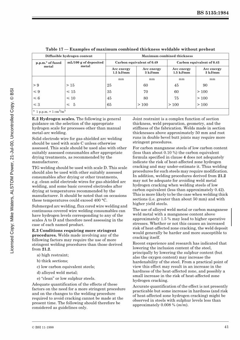
BS 5135:1984
© BSI 11-1998 41
Table 17 — Examples of maximum combined thickness weldable without preheat
E.2 Hydrogen scales. The following is general guidance on the selection of the appropriate hydrogen scale for processes other than manual metal-arc welding.Solid electrode wire for gas-shielded arc welding should be used with scale C unless otherwise assessed. This scale should be used also with other suitably assessed consumables after appropriate drying treatments, as recommended by the manufacturer.TIG welding should be used with scale D. This scale should also be used with other suitably assessed consumables after drying or other treatments, e.g. clean solid electrode wires for gas-shielded arc welding, and some basic covered electrodes after drying at temperatures recommended by the manufacturer. It should be noted that on occasions these temperatures could exceed 400 °C.Submerged arc welding, flux cored wire welding and continuous covered wire welding consumables can have hydrogen levels corresponding to any of the scales A to D and therefore need assessing in the case of each named product.E.3 Conditions requiring more stringent procedures. Welds made involving any of the following factors may require the use of more stringent welding procedures than those derived from 21.2.
a) high restraint;b) thick sections;c) low carbon equivalent steels;d) alloyed weld metal;e) “clean” or low sulphur steels.
Adequate quantification of the effects of these factors on the need for a more stringent procedure and on the changes to the welding procedure required to avoid cracking cannot be made at the present time. The following should therefore be considered as guidelines only.
Joint restraint is a complex function of section thickness, weld preparation, geometry, and the stiffness of the fabrication. Welds made in section thicknesses above approximately 50 mm and root runs in double bevel butt joints may require more stringent procedures.For carbon manganese steels of low carbon content (less than about 0.10 %) the carbon equivalent formula specified in clause 4 does not adequately indicate the risk of heat-affected zone hydrogen cracking and may under-estimate it. Thus welding procedures for such steels may require modification. In addition, welding procedures derived from 21.2 may not be adequate for avoiding weld metal hydrogen cracking when welding steels of low carbon equivalent (less than approximately 0.42). This is more likely to be the case when welding thick sections (i.e. greater than about 50 mm) and with higher yield steels.The use of alloyed weld metal or carbon manganese weld metal with a manganese content above approximately 1.5 % may lead to higher operative stresses. Whether or not this causes an increased risk of heat-affected zone cracking, the weld deposit would generally be harder and more susceptible to cracking itself.Recent experience and research has indicated that lowering the inclusion content of the steel, principally by lowering the sulphur content (but also the oxygen content) may increase the hardenability of the steel. From a practical point of view this effect may result in an increase in the hardness of the heat-affected zone, and possibly a small increase in the risk of heat-affected zone hydrogen cracking.Accurate quantification of the effect is not presently practicable but some increase in hardness (and risk of heat-affected zone hydrogen cracking) might be observed in steels with sulphur levels less than approximately 0.008 % (m/m).
Diffusible hydrogen content Maximum combined thickness
p.p.m.a of fused metal
mL/100 g of deposited metal
Carbon equivalent of 0.49 Carbon equivalent of 0.43
Arc energy 1.5 kJ/mm
Arc energy 3 kJ/mm
Arc energy 1.5 kJ/mm
Arc energy 3 kJ/mm
mm mm mm mm
> 9 > 15 25 60 45 90
< 9 < 15 35 70 60 > 100
< 6 < 10 45 80 75 > 100
< 3 < 5 65 > 100 > 100 > 100a 1 p.p.m. = 1 cm3/m3
Lice
nsed
Cop
y: M
ike
Wat
ers,
ALS
TO
M P
ower
, 21-
Jul-0
0, U
ncon
trol
led
Cop
y. ©
BS
I

BS 5135:1984
42 © BSI 11-1998
Although modifications to the procedures derived from 21.2 to deal with welds involving the above factors can, in principle, be obtained through a change in arc energy or preheat or weld hydrogen level, the most effective modification is to lower the weld hydrogen level. This can be done either directly, by lowering the hydrogen input to the weld (use of lower hydrogen welding processes or consumables), or by increasing hydrogen loss from the weld by diffusion through the use of higher preheat and interpass temperatures, and/or by maintaining the preheat as a post-heat for a period of time after welding. The required post-heat time will depend on many factors, but a period of 2 h to 3 h has been found to be beneficial in many instances. It is recommended that the required modifications to the procedures be derived by the use of adequate joint simulation weld testing.E.4 Relaxations. Relaxations of the welding procedures determined from 21.2 may be possible under the following conditions.
a) General preheating. If the whole component or a width more than twice that stated in 21.2 is preheated, it is generally possible to reduce the preheating temperature by up to 50 °C.b) Limited heat sink. If the heat sink is limited in one or more directions (e.g. when the shortest heat path is less than ten times the fillet leg length) especially in the thicker plate (e.g. in the case of a lap joint where the outstand is only marginally greater than the fillet weld leg length), it is possible to reduce preheating levels.c) Austenitic electrodes. In some circumstances where sufficient preheating to ensure crack-free welds is impracticable an advantage may be gained by using certain austenitic electrodes, for example class 19.12.3 or 25.20 in BS 2926 or high nickel alloy. In such cases preheat may not be necessary, especially if the condition of the electrode coating is such as to deposit weld metal containing very low levels of hydrogen.d) Joint geometry. Close fit fillet welds (where the gap is 0.5 mm or less) and root runs in single V butt welds may justify relaxations in the welding procedure.
E.5 ExampleStep 1. Decide carbon equivalent value using Table 2, 21.2.1, 21.2.2 and E.3. Assume steel is BS 4360: Grade 50C, not controlled rolled.Table 2 gives a carbon equivalent of 0.45.Step 2. Decide provisionally on welding process and consumables. Classify as hydrogen scale A, B, C or D using 21.2.3 and Table 1 to determine which carbon equivalent scale to use.
Assume manual metal-arc welding using hydrogen controlled electrodes complying with BS 639, and that the weld hydrogen level is appropriate to scale B in Table 1.Step 3. Decide whether fillet or butt weld and refer to Table 2.Assume fillet weld.Table 2 refers to Table 7.Step 4. Decide minimum specified individual fillet leg length required by design drawing.Assume 5 mm.Table 7, hydrogen scale B, 5 mm leg length now requires step 5.Step 5. Decide combined thickness of joint to be welded with single run fillet of 5 mm leg length.Refer to 21.2.5.Assume calculated combined thickness of 70 mm.Step 6. Return to Table 7 and read off the minimum preheat required: hydrogen scale B, 5 mm fillet, 70 mm combined thickness requires 100 °C preheat.Step 7. Table 7 and Table 13 give arc energy values (see 21.2.6) corresponding to the 5 mm fillet using the particular electrode chosen (1.7 kJ/mm).Table 10, Table 11 and Table 12 give the electrode size and runout conditions which correspond. Thus Table 11 offers a choice of electrode sizes and run lengths from 450 mm of electrode ranging:
from 3.2 mm diameter and 145 mm run lengthto 8 mm diameter and 910 mm run length.
Practical considerations would probably limit this to a maximum diameter of 5 mm electrode and corresponding run length of 355 mm.Variation at step 3Step A. Assume butt weld.Table 2 refers to Figure 4(a), Figure 4(e), Figure 4(g) and Figure 4(h).Figure 4(g) is relevant to 0.45 carbon equivalent and hydrogen scale B.Step B. Decide minimum run dimension to be used in making butt weld. This will most often be the root run.Assume 4 mm electrode to be run out in about 320 mm of run length.Refer to Table 11. This gives minimum arc energy for individual runs forming the butt weld of 1.2 kJ/mm.Step C. Decide combined thickness of butt joint, referring to 21.2.5.Assume calculated combined thickness of 50 mm.
Licensed Copy: M
ike Waters, A
LST
OM
Pow
er, 21-Jul-00, Uncontrolled C
opy. © B
SI

BS 5135:1984
© BSI 11-1998 43
Step D. Return to Figure 4(g) and plot coordinates of 1.2 kJ/mm arc energy and 50 mm combined thickness.Read off minimum preheating and interpass temperature required (by interpolation, if necessary, or by reading the preheat line immediately above or to the left of the coordinated point) which in this example is 100 °C.Variation at either step 7 or step D. In the event that preheat is undesirable, proceed as follows.Step W. Re-examine Figure 4(g) to determine minimum arc energy for no preheat (20 °C line, normally).For fillet example: 2.2 kJ/mmFor butt example: 1.6 kJ/mmStep X. If by reference to Table 11 these arc energies are feasible, proceed using electrode diameter and run length chosen from Table 11.If not feasible, proceed to step Y.Step Y. Using Table 7 for the fillet weld example and Figure 4(a) and Figure 4(e) for the butt weld example, examine the feasibility of using lower hydrogen levels (by the use of higher electrode drying temperatures or change of consumables) to avoid the need for preheat at acceptable arc energy levels.
Appendix F Guidance on solidification crackingF.1 Solidification cracking of the weld metal is usually found as centreline cracking. It is more often found in root runs and, although frequently open at the surface and visible after deslagging, may be just below the surface and covered by up to 0.5 mm of sound metal. Solidification cracks can be deep and can seriously reduce the efficiency of a joint. When welding carbon manganese steels, this type of cracking is most commonly found in submerged arc welds, rarely with manual metal-arc welding but can sometimes be a problem with gas and self-shielded processes.
F.2 Solidification cracking is associated with impurities, particularly sulphur and phosphorus, and is promoted by carbon picked up from the parent metal at high dilution levels whilst manganese reduces the risk of cracking. Because welding consumables are generally purer than the materials being welded, impurity levels and crack susceptibilities are usually greatest in weld runs of high dilution, e.g. root runs of butt welds. To minimize the risk of cracking, consumables are preferred with low carbon and impurity levels and relatively high manganese contents.F.3 For submerged arc welds a formula2) has been developed in which the solidification crack susceptibility in arbitrary units known as units of crack susceptibility (UCS) has been related to the composition of the weld metal (in % (m/m)) as follows:
230C + 190S + 75P + 45Nb – 12.3Si – 5.4 Mn –1This formula is valid for weld metal containing the following:
Alloying elements and impurities in the weld metal up to the following limits do not exert a marked effect on values of UCS:
In the above formula, values of less than 10 UCS indicate a high resistance to cracking and above 30 a low resistance. Within these approximate limits the risk of cracking is higher in weld runs with a high depth/width ratio, made at high welding speeds or where fit-up is near the maximum allowable.
2) See BAILEY, N., and JONES, S.B. Solidification cracking of ferritic steels during submerged arc welding. The Welding Institute, 1977.
C 0.03a to 0.23
S 0.010 to 0.050
P 0.010 to 0.045
Si 0.15 to 0.65
Mn 0.45 to 1.6
Nb 0 to 0.07a C contents of less than 0.08 % to be taken as equal to 0.08 %.
1 % Ni 0.02 % Ti
0.5 % Cr 0.03 % Al
0.4 % Mo 0.002 % B
0.07 % V 0.01 % Pb
0.3 % Cu 0.03 % Co
Lice
nsed
Cop
y: M
ike
Wat
ers,
ALS
TO
M P
ower
, 21-
Jul-0
0, U
ncon
trol
led
Cop
y. ©
BS
I
BS 5135:1984
44 © BSI 11-1998
For fillet weld runs having a depth/width ratio of about 1.0, UCS values of 20 and above indicate a risk of cracking whilst for butt welds the values of about 25 UCS are critical. Decreasing the depth/width ratio from 1.0 to 0.8 in fillet welds may increase the allowable UCS by about 9. However, very low depth/width ratios, such as are obtained when penetration into the root is not achieved, also promote cracking.
Appendix G Guidance on lamellar tearingG.1 General. In certain types of joint, where the welding contraction strains act in the through-thickness (short transverse) direction of a plate, lamellar tearing may occur. Lamellar tearing is a parent metal phenomenon which occurs mainly in plate material. The risk of cracking is influenced by two factors: plate susceptibility and strain across the joint. With very susceptible plate, tearing can occur even if strains are low, i.e. in a joint of low restraint. More resistant materials might not tear unless used in situations which imposed very high through-thickness strains.G.2 Plate susceptibility. Since lamellar tearing occurs when the non-metallic inclusions in a plate link up under the influence of welding strains, plate susceptibility is controlled by the quantity and distribution of the inclusions it contains. At present there is no reliable non-destructive technique for detecting these inclusions. The short transverse tensile test can be used to assess susceptibility (see Figure 10) and the short transverse reduction of area (STRA) has been correlated with the incidence of lamellar tearing in different types of fabrication (see Figure 11). In the case of low oxygen steels (aluminium treated or vacuum degassed types), sulphur content has been found to be a useful guide to the inclusion content and thus to the STRA. Figure 12 gives the likely lowest and highest values of STRA to be expected in an aluminium treated steel of a given sulphur content. The data are for plate 12.5 mm to 50 mm thick but it should be noted that the relationship of STRA (in %) to sulphur content (in %) is to some extent thickness dependent.Steels giving reduction of area values of over 20 % STRA are considered lamellar tearing resistant and materials with guaranteed STRA are available. These are usually aluminium treated steels of low sulphur content, although additions of rare earth or calcium compounds may also be made both to reduce the inclusion content and to favourably alter the inclusion shapes.
When appropriate, the contractor should discuss with the steelmaker the supply of lamellar tearing resistant steel.G.3 Joint configuration and through-thickness strains. The risk of lamellar tearing for a given steel increases with through-thickness strain, and the latter is usually high in joints of high tensile restraint. However, tearing may also occur if the bending restraint is low, since angular distortion can increase the strain in weld root or toe areas (see Figure 13). In some cases, design changes can be made which reduce the through-thickness strain. Examples of the types of detail and joint configuration in which lamellar tearing is possible are shown in Figure 14, typical locations of the cracks being illustrated. If the plate susceptibility is suspected to be high, susceptible joints and details should be modified or avoided. For example, the T-fillet (Figure 14(d)) is less susceptible than the T-butt (Figure 14(e)) and the set on nozzle is less susceptible than the set through nozzle. Also a chamfer could be applied to the horizontal plate in Figure 14(f) so that welding stresses would no longer be perpendicular to the plate. Replacing a susceptible plate connection by a casting or forging may also be possible.In most structures of any size and complexity, some joints will have to be made in such a way that considerable through-thickness strains are present. In such cases, lamellar tearing resistant plate is advisable. If this is not done and the material is found to be susceptible, buttering with weld metal may enable a sound joint to be achieved by taking up contraction strains in the non-susceptible buttering layer, although this method cannot be guaranteed to prevent lamellar tearing.G.4 Hydrogen cracking and lamellar tearing. Although lamellar tearing can occur even when very low hydrogen levels (scale D) are achieved, defects can be formed by a combination of the two mechanisms, so low-hydrogen precautions (scale D conditions), e.g. very low hydrogen processes, or high temperature drying of covered electrodes, in accordance with manufacturers recommendations, are advisable when dealing with susceptible material, particularly in the case of repairs. Excessive preheating is often not beneficial and preheat should be applied in such a way that it does not increase the amount of contraction across the weld, e.g. avoid preheating only the nozzle in Figure 14(a).
Licensed Copy: M
ike Waters, A
LST
OM
Pow
er, 21-Jul-00, Uncontrolled C
opy. © B
SI
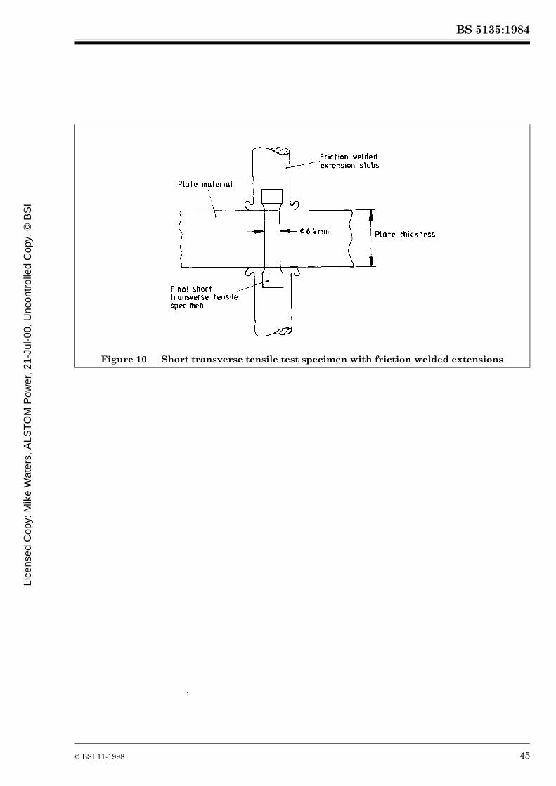
BS 5135:1984
© BSI 11-1998 45
Figure 10 — Short transverse tensile test specimen with friction welded extensions
Lice
nsed
Cop
y: M
ike
Wat
ers,
ALS
TO
M P
ower
, 21-
Jul-0
0, U
ncon
trol
led
Cop
y. ©
BS
I

BS 5135:1984
46 © BSI 11-1998
Figure 11 — Suggested STRA values appropriate to risk of lamellar tearing in joints of differing restraint (values based on 6.4 mm diameter specimen)
Licensed Copy: M
ike Waters, A
LST
OM
Pow
er, 21-Jul-00, Uncontrolled C
opy. © B
SI
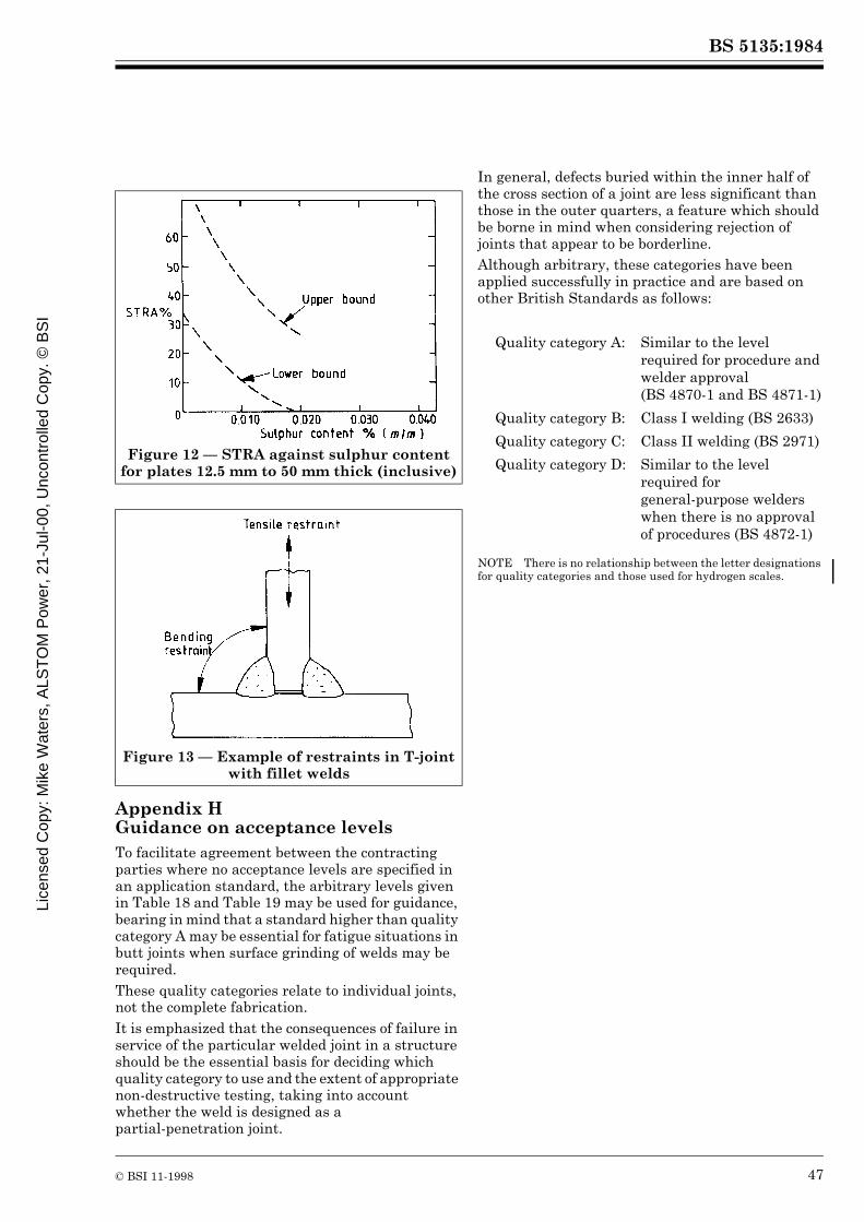
BS 5135:1984
© BSI 11-1998 47
Appendix H Guidance on acceptance levelsTo facilitate agreement between the contracting parties where no acceptance levels are specified in an application standard, the arbitrary levels given in Table 18 and Table 19 may be used for guidance, bearing in mind that a standard higher than quality category A may be essential for fatigue situations in butt joints when surface grinding of welds may be required.These quality categories relate to individual joints, not the complete fabrication.It is emphasized that the consequences of failure in service of the particular welded joint in a structure should be the essential basis for deciding which quality category to use and the extent of appropriate non-destructive testing, taking into account whether the weld is designed as a partial-penetration joint.
In general, defects buried within the inner half of the cross section of a joint are less significant than those in the outer quarters, a feature which should be borne in mind when considering rejection of joints that appear to be borderline.Although arbitrary, these categories have been applied successfully in practice and are based on other British Standards as follows:
NOTE There is no relationship between the letter designations for quality categories and those used for hydrogen scales.
Figure 12 — STRA against sulphur content for plates 12.5 mm to 50 mm thick (inclusive)
Figure 13 — Example of restraints in T-joint with fillet welds
Quality category A: Similar to the level required for procedure and welder approval (BS 4870-1 and BS 4871-1)
Quality category B: Class I welding (BS 2633)
Quality category C: Class II welding (BS 2971)
Quality category D: Similar to the level required for general-purpose welders when there is no approval of procedures (BS 4872-1)
Lice
nsed
Cop
y: M
ike
Wat
ers,
ALS
TO
M P
ower
, 21-
Jul-0
0, U
ncon
trol
led
Cop
y. ©
BS
I
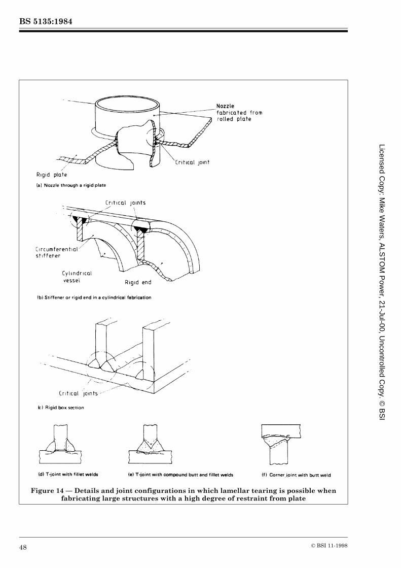
BS 5135:1984
48 © BSI 11-1998
Figure 14 — Details and joint configurations in which lamellar tearing is possible when fabricating large structures with a high degree of restraint from plate
Licensed Copy: M
ike Waters, A
LST
OM
Pow
er, 21-Jul-00, Uncontrolled C
opy. © B
SI

BS 5135:1984
© BSI 11-1998 49
Table 18 — Guidance on acceptance levels for butt jointsNotation:
t is parent metal thickness
l is length of defect
h is height of defect
w is width of defect
Quality category A B C D
Minimum amount of volumetric non-destructive testing
100 % 10 % each weldera 10 % overalla None 100 % visual only
Cracks Not permittedb Not permittedb Not permittedb Not permittedb
Lack of fusion Lack of root penetration
Not permittedb t < 20 mm: l < 10 mm h < 2 mm
t > 20 mm: l < 15 mm h < 2 mm
l < 25 mm in any 100 mmlength of weld or h < 0.2 t
l < 25 % of length of weld(applicable only to joints welded from one side)
Individual slaginclusions
t < 18 mm: l < t/2 < 6 mm w < 1.5 mm
t > 18 mm < 75 mm: l < t/3 w < 1.5 mm
t > 75 mm: l < 25 mm w < 1.5 mm
t < 20 mm: l < 12 mm w < 1.5 mm
t > 20 mm: l < 20 mm w < 1.5 mm
l < 25 mm in any 100 mm length of weldw < 1.5 mm
Not applicable
Lineargroup of inclusions
Aggregate length < 8 % of length of group which in turn is not to exceed 12 t in length
Any length of group provided adjacent groups are separated by a distance of at least 4 times the length of longest defect for t < 20 mm and by a distance of at least 6 times the length of longest defect for t > 20 mm
Any length of group provided adjacent groups are separated by a distance of at least 4 times the length of longest defect
Not applicable
Porosityc Individual pores: < 2 mm diameter.Localized: < 2 % by aread for t < 50 mm then pro rata for greater thicknesses
Individual pores: < 2.5 mm diameter. Localized: < 3 % by aread
Individual pores: < 3 mm diameter < 0.25 t diameter. Localized: < 4 % by aread
Surface porosity Individual pores: < 3 mm diameter < 0.25 t diameter Localized: < 4 % by aread
Undercut Intermittent, 0.5 mm maximum in depth
Intermittent, 0.5 mm maximum in depth
Intermittent, 0.5 mm maximum in depth
Depth < 0.1 t < 1 mm l < 10 % of length of weld
a When random volumetric non-destructive testing reveals unacceptable defects in a joint, two further joints in the group represented by this joint should be tested similarly. If the results on these two further joints are acceptable then the original weld should be repaired and retested by similar non-destructive means. If the repair is satisfactory then the group of joints should be accepted.If the non-destructive testing of the two further joints reveals unacceptable defects, each joint in the group should be non-destructively tested. Unacceptable defects should be repaired and retested by similar non-destructive means.b This does not mean that the whole joint is rejectable, merely that attention be given to the particular area, e.g. local repair or grinding without welding.c If found during ultrasonic examination, then check-radiography should also be applied.d The area to be considered should be the length of weld affected by porosity times the maximum width of the weld.
Lice
nsed
Cop
y: M
ike
Wat
ers,
ALS
TO
M P
ower
, 21-
Jul-0
0, U
ncon
trol
led
Cop
y. ©
BS
I
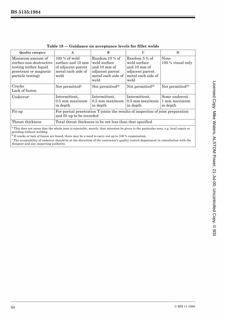
BS 5135:1984
50 © BSI 11-1998
Table 19 — Guidance on acceptance levels for fillet welds
Quality category A B C D
Minimum amount of surface non-destructive testing (either liquid penetrant or magnetic particle testing)
100 % of weld surface and 10 mm of adjacent parent metal each side of weld
Random 10 % of weld surface and 10 mm of adjacent parent metal each side of weld
Random 5 % of weld surface and 10 mm of adjacent parent metal each side of weld
None 100 % visual only
Cracks Lack of fusion
Not permitteda Not permittedab Not permittedab Not permittedab
Undercutc Intermittent, 0.5 mm maximum in depth
Intermittent, 0.5 mm maximum in depth
Intermittent, 0.5 mm maximum in depth
Some undercut 1 mm maximum in depth
Fit-up For partial penetration T-joints the results of inspection of joint preparation and fit-up to be recorded
Throat thickness Total throat thickness to be not less than that specifieda This does not mean that the whole joint is rejectable, merely, that attention be given to the particular area, e.g. local repair or grinding without welding.b If cracks or lack of fusion are found, there may be a need to carry out up to 100 % examination.c The acceptability of undercut should be at the discretion of the contractor’s quality control department in consultation with the designer and any inspecting authority.
Licensed Copy: M
ike Waters, A
LST
OM
Pow
er, 21-Jul-00, Uncontrolled C
opy. © B
SI
BS 5135:1984
© BSI 11-1998
Publications referred to
BS 153, Steel girder bridges.BS 153-3B & BS 153-4, 3B. Stresses 4. Design and construction.BS 449, The use of structural steel in building.BS 449-2, Metric units.BS 499, Welding terms and symbols.BS 499-1, Glossary for welding, brazing and thermal cutting.BS 499-2, Specification for symbols for welding.BS 638, Arc welding power sources, equipment and accessories.BS 639, Covered electrodes for the manual metal-arc welding of carbon and carbon manganese steels.BS 2633, Class I arc welding of ferritic steel pipework for carrying fluids.BS 2901, Filler rods and wires for gas-shielded arc welding.BS 2901-1, Ferritic steels.BS 2926, Chromium-nickel austenitic and chromium steel electrodes for manual metal-arc welding.BS 2971, Specification for class II arc welding of carbon steel pipework for carrying fluids.BS 4105, Liquid carbon dioxide, industrial.BS 4165, Electrode wires and fluxes for the submerged arc welding of mild steel and medium-tensile steel.BS 4360, Specification for weldable structural steels.BS 4365, Industrial argon.BS 4570, Fusion welding of steel castings.BS 4870, Approval testing of welding procedures.BS 4870-1, Fusion welding of steel.BS 4871 , Approval testing of welders working to approved welding procedures.BS 4871-1, Fusion welding of steel.BS 4872, Approval testing of welders when welding procedure approval is not required.BS 4872-1, Fusion welding of steel.BS 5400, Steel, concrete and composite bridges.BS 5400-10, Code of practice for fatigue.BS 6084, Method of test for comparison of prefabrication primers by porosity rating in arc welding.
Lice
nsed
Cop
y: M
ike
Wat
ers,
ALS
TO
M P
ower
, 21-
Jul-0
0, U
ncon
trol
led
Cop
y. ©
BS
I
BSI389 Chiswick High RoadLondonW4 4AL
|||||||||||||||||||||||||||||||||||||||||||||||||||||||||||||||||||||||||||||||||||||||||||||||||||||||||||||||||||||||||||||||
BSI Ð British Standards Institution
BSI is the independent national body responsible for preparing British Standards. Itpresents the UK view on standards in Europe and at the international level. It isincorporated by Royal Charter.
Revisions
British Standards are updated by amendment or revision. Users of British Standardsshould make sure that they possess the latest amendments or editions.
It is the constant aim of BSI to improve the quality of our products and services. Wewould be grateful if anyone finding an inaccuracy or ambiguity while using thisBritish Standard would inform the Secretary of the technical committee responsible,the identity of which can be found on the inside front cover. Tel: 020 8996 9000.Fax: 020 8996 7400.
BSI offers members an individual updating service called PLUS which ensures thatsubscribers automatically receive the latest editions of standards.
Buying standards
Orders for all BSI, international and foreign standards publications should beaddressed to Customer Services. Tel: 020 8996 9001. Fax: 020 8996 7001.
In response to orders for international standards, it is BSI policy to supply the BSIimplementation of those that have been published as British Standards, unlessotherwise requested.
Information on standards
BSI provides a wide range of information on national, European and internationalstandards through its Library and its Technical Help to Exporters Service. VariousBSI electronic information services are also available which give details on all itsproducts and services. Contact the Information Centre. Tel: 020 8996 7111.Fax: 020 8996 7048.
Subscribing members of BSI are kept up to date with standards developments andreceive substantial discounts on the purchase price of standards. For details ofthese and other benefits contact Membership Administration. Tel: 020 8996 7002.Fax: 020 8996 7001.
Copyright
Copyright subsists in all BSI publications. BSI also holds the copyright, in the UK, ofthe publications of the international standardization bodies. Except as permittedunder the Copyright, Designs and Patents Act 1988 no extract may be reproduced,stored in a retrieval system or transmitted in any form or by any means ± electronic,photocopying, recording or otherwise ± without prior written permission from BSI.
This does not preclude the free use, in the course of implementing the standard, ofnecessary details such as symbols, and size, type or grade designations. If thesedetails are to be used for any other purpose than implementation then the priorwritten permission of BSI must be obtained.
If permission is granted, the terms may include royalty payments or a licensingagreement. Details and advice can be obtained from the Copyright Manager.Tel: 020 8996 7070.
Licensed Copy: M
ike Waters, A
LST
OM
Pow
er, 21-Jul-00, Uncontrolled C
opy. © B
SI