bridging the gap between asynchronous design and designers part ii: logic synthesis from concurrent...
Post on 21-Dec-2015
220 views
TRANSCRIPT

Bridging the gap between asynchronous design
and designers
Part II:
Logic synthesis fromconcurrent specifications

Outline
• Overview of the synthesis flow
• Specification
• State graph and next-state functions
• State encoding
• Implementability conditions
• Review of some advanced topics

Book and synthesis tool
• J. Cortadella, M. Kishinevsky, A. Kondratyev,L. Lavagno and A. Yakovlev,Logic synthesis for asynchronouscontrollers and interfaces,Springer-Verlag, 2002
• petrify:http://www.lsi.upc.es/~petrify

4
Specification(STG)
State Graph
SG withCSC
Next-state functions
Decomposed functions
Gate netlist
Reachability analysis
State encoding
Boolean minimization
Logic decomposition
Technology mapping
Design flow

x
y
z
x+
x-
y+
y-
z+
z-
Signal Transition Graph (STG)(Petri Net with interpreted events (often free-choice))
xy
z
Specification

x
y
z
x+
x-
y+
y-
z+
z-
Token flow

x+
x-
y+
y-
z+
z-
xyz000
x+
100y+z+
z+y+
101 110
111
x-
x-
001
011y+
z-
010
y-
State graph

x z x y ( )
y z x
z x y z
Next-state functionsxyz000
x+
100y+z+
z+y+
101 110
111
x-
x-
001
011y+
z-
010
y-

x
z
y
Gate netlist
x z x y ( )
y z x
z x y z

10
Specification(STG)
State Graph
SG withCSC
Next-state functions
Decomposed functions
Gate netlist
Reachability analysis
State encoding
Boolean minimization
Logic decomposition
Technology mapping
Design flow

VME bus
DeviceLDS
LDTACK
D
DSr
DSw
DTACK
VME BusController
DataTransceiver
BusDSr
LDS
LDTACK
D
DTACK
Read Cycle

STG for the READ cycle
LDS+ LDTACK+ D+ DTACK+ DSr- D-
DTACK-
LDS-LDTACK-
DSr+
LDS
LDTACK
D
DSr
DTACK
VME BusController

Choice: Read and Write cycles
DSr+
LDS+
LDTACK+
D+
DTACK+
DSr-
D-
DTACK-
LDS-
LDTACK-
DSw+
D+
LDS+
LDTACK+
D-
DTACK+
DSw-
DTACK-
LDS-
LDTACK-
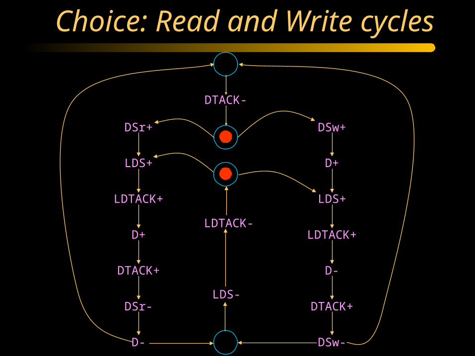
Choice: Read and Write cycles
DTACK-
DSr+
LDS+
LDTACK+
D+
DTACK+
DSr-
D-
LDS-
LDTACK-
DSw+
D+
LDS+
LDTACK+
D-
DTACK+
DSw-

Circuit synthesis
• Goal:– Derive a hazard-free circuit
under a given delay model andmode of operation

Speed independence
• Delay model– Unbounded gate / environment delays
– Certain wire delays shorter than certain paths in the circuit
• Conditions for implementability:– Consistency
– Complete State Coding
– Persistency

17
Specification(STG)
State Graph
SG withCSC
Next-state functions
Decomposed functions
Gate netlist
Reachability analysis
State encoding
Boolean minimization
Logic decomposition
Technology mapping
Design flow

STG for the READ cycle
LDS+ LDTACK+ D+ DTACK+ DSr- D-
DTACK-
LDS-LDTACK-
DSr+
LDS
LDTACK
D
DSr
DTACK
VME BusController

Binary encoding of signals
DSr+
DSr+
DSr+
DTACK-
DTACK-
DTACK-
LDS-LDS-LDS-
LDTACK- LDTACK- LDTACK-
D-
DSr-DTACK+
D+
LDTACK+
LDS+

Binary encoding of signals
DSr+
DSr+
DSr+
DTACK-
DTACK-
DTACK-
LDS-LDS-LDS-
LDTACK- LDTACK- LDTACK-
D-
DSr-DTACK+
D+
LDTACK+
LDS+
10000
10010
10110 01110
01100
0011010110
(DSr , DTACK , LDTACK , LDS , D)

QR (LDS+)QR (LDS+)
QR (LDS-)QR (LDS-)
Excitation / Quiescent Regions
ER (LDS+)ER (LDS+)
ER (LDS-)ER (LDS-)
LDS-LDS-
LDS+
LDS-

Next-state function
0 1
LDS-LDS-
LDS+
LDS-
1 0
0 0
1 1

Next-state function. Exercise
A+
C-
A-
C+
B+
B-

Next-state function
0 1
LDS-LDS-
LDS+
LDS-
1 0
0 0
1 1
1011010110
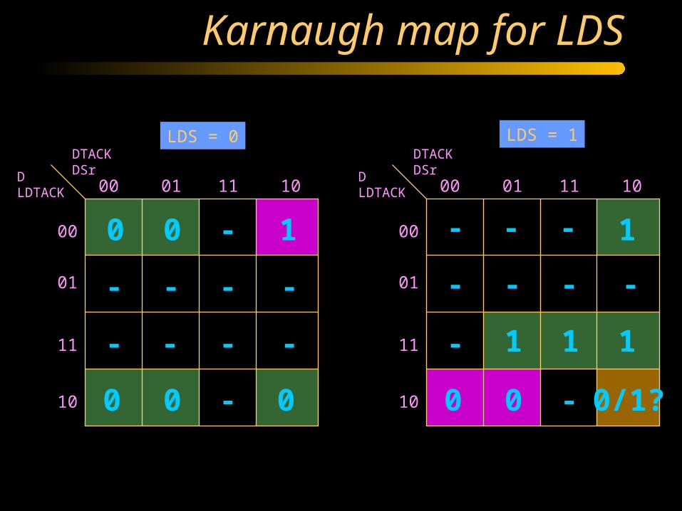
Karnaugh map for LDS
DTACKDSrD
LDTACK 00 01 11 10
00
01
11
10
DTACKDSrD
LDTACK 00 01 11 10
00
01
11
10
LDS = 0 LDS = 1
0 1-0
0 0 0 0 0 0/1?
1
111
-
-
-
---
- - - -
-
- ---
- - -

26
Specification(STG)
State Graph
SG withCSC
Next-state functions
Decomposed functions
Gate netlist
Reachability analysis
State encoding
Boolean minimization
Logic decomposition
Technology mapping
Design flow

Concurrency reduction
LDS-LDS-
LDS+
LDS-
1011010110
DSr+
DSr+
DSr+

Concurrency reduction
LDS+ LDTACK+ D+ DTACK+ DSr- D-
DTACK-
LDS-LDTACK-
DSr+

State encoding conflicts
LDS-
LDTACK-
LDTACK+
LDS+
10110
10110
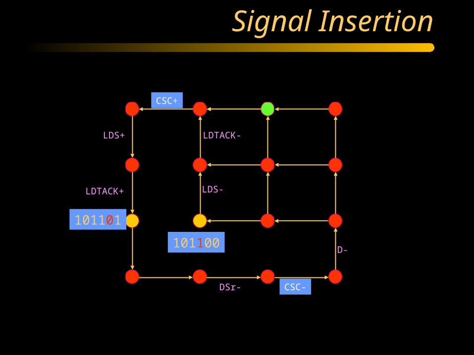
Signal Insertion
LDS-
LDTACK-
D-
DSr-
LDTACK+
LDS+
CSC-
CSC+
101101
101100

Regions and excitation regions
• Region = set of states r s.t. each event a
either enters, or exits or does not cross it (Nielsen et el. 92)
• Pre-region: a exits r
• Post-region: a enters r
• Excitation region: all states exited by a
• Any region is a union of minimal regions
a a
a a
a
aa a
enter exit non-cross excitation region

Event insertion (Vanbekbergen ‘92)
a b c
ER(x)
b c
ER(x)
ab
SR(x)
x x x x
delay exit
transitions
by xS - ER(x)
S - ER(x)

• Properties to preserve during insertion:– trace equivalence– speed-independence
necessary and sufficient conditions:• persistency
(Speed-Independence Preserving set)
commutativity
Event insertion (Vanbekbergen ‘92)
a b
ab
a b
ab

Regions and SIP sets
• Legal SIP set:
– region
– persistent excitation region
– exit border of persistent region
– intersection of pre-regions(if forward connected)

State signal insertion (Vanbekbergen ‘92)
• S+ (ER(x+)) and S- (ER(x-)) must be SIP (speed-independence)
• I-partition must not have illegal arcs (well-formedness)e.g. S0 S1, S+ S0, S1 S+ are illegal
S0
S1S-S+
x+ x-S0
S1 S-S+
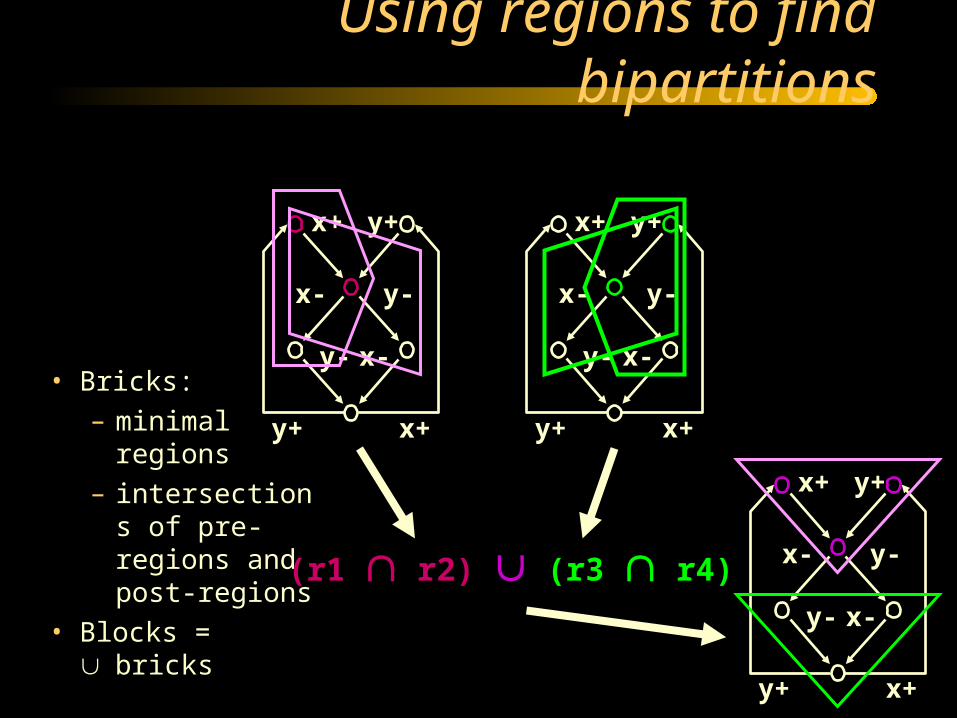
Using regions to find bipartitions
• Bricks:– minimal regions– intersections of
pre-regions and post-regions
• Blocks = bricks
x+ y+
y+ x+
y-
y-
x-
x-
x+ y+
y+ x+
y-
y-
x-
x-
(r1 r2) (r3 r4)
x+ y+
y+ x+
y-
y-
x-
x-

From bipartition to I-partition
• Find a bipartition {b, b}
• Find (by expansion) exit borders which are
well-formed and SIP
• Add the new state signal z
x+ y+
y+ x+
y-
y-
x-
x-
x+ y+
y+ x+
y-
y-
x-
x-
x+ y+
y+ x+
y-
y-
x-
x-
100 010
110
111
011 101
001
000
z-
z-

The cost function
• Comparison among pairs of I-partitions:– correctness (SIP, well-formed, ...)– number of solved CSC conflicts– estimation of logic
• Trade-off between CSC conflicts and estimated logic
Conclusions
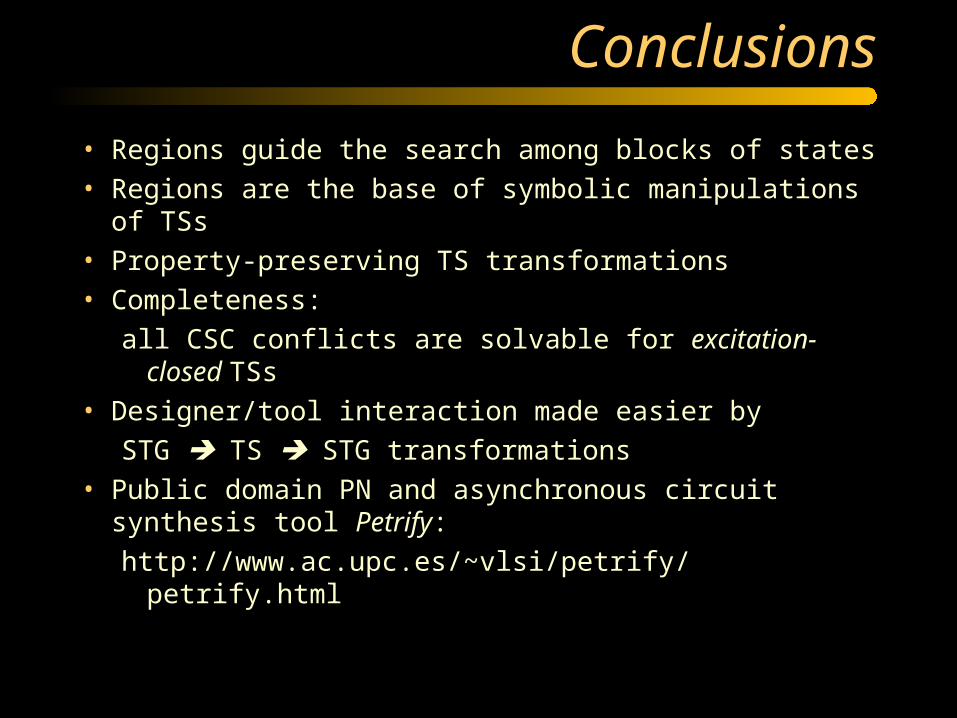
• Regions guide the search among blocks of states
• Regions are the base of symbolic manipulations of TSs
• Property-preserving TS transformations
• Completeness:
all CSC conflicts are solvable for excitation-closed TSs
• Designer/tool interaction made easier by
STG TS STG transformations
• Public domain PN and asynchronous circuit synthesis tool Petrify:
http://www.ac.upc.es/~vlsi/petrify/petrify.html

40
Specification(STG)
State Graph
SG withCSC
Next-state functions
Decomposed functions
Gate netlist
Reachability analysis
State encoding
Boolean minimization
Logic decomposition
Technology mapping
Design flow

Complex-gate implementation
)(csccsc
csc
csc
LDTACKDSr
LDTACKD
DDTACK
DLDS

Implementability conditions
• Boundedness (reachability space is finite)
• Consistency– Rising and falling transitions of each signal
alternate in any trace
• Complete state coding (CSC)– Next-state functions correctly defined
• Persistency– No event can be disabled by another event
(unless they are both inputs)
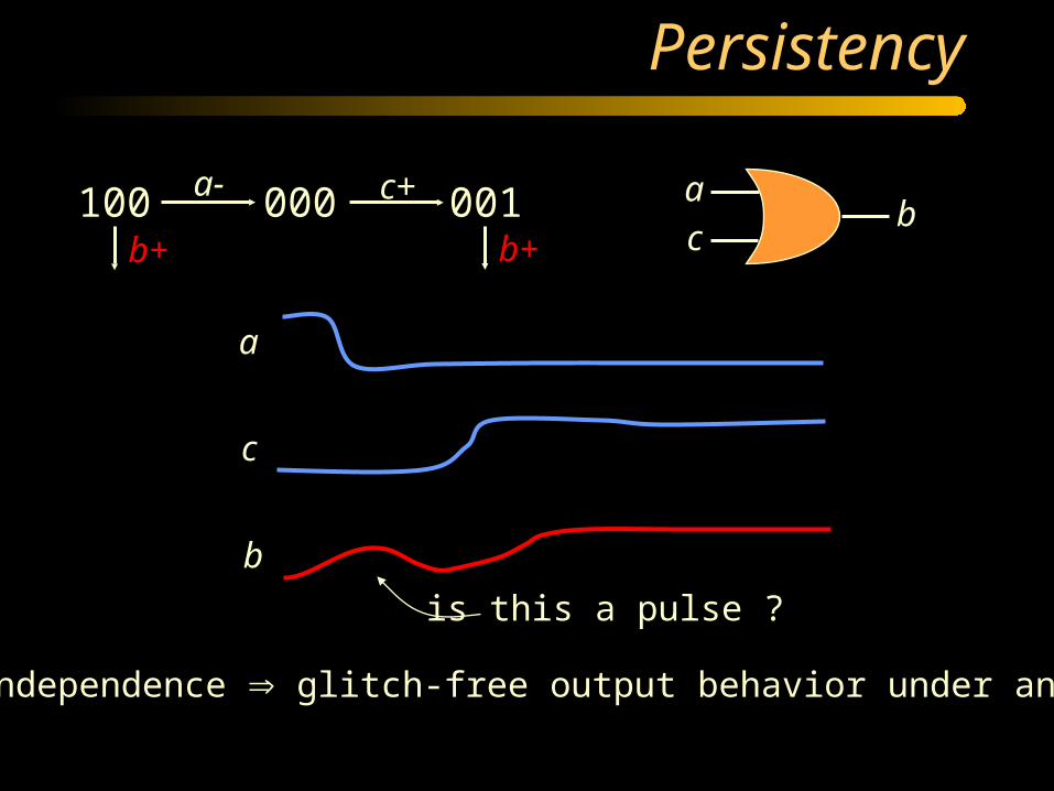
Persistency
100 000 001a- c+
b+ b+
a
cb
a
c
b
is this a pulse ?
Speed independence glitch-free output behavior under any delay
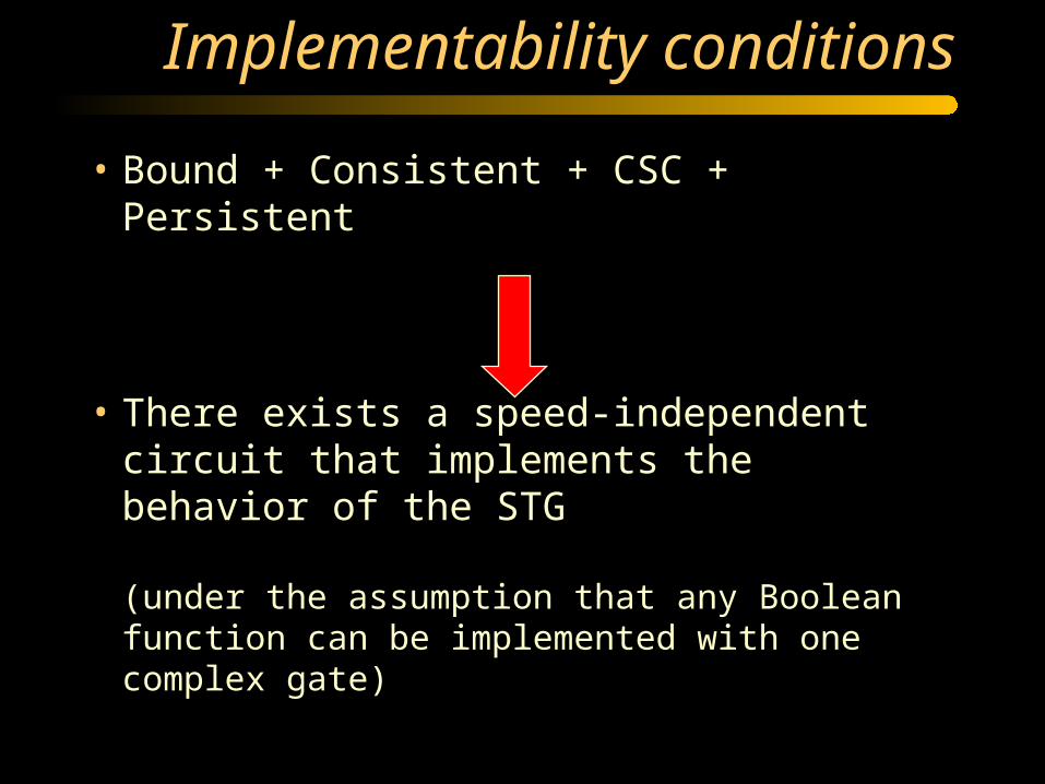
Implementability conditions
• Bound + Consistent + CSC + Persistent
• There exists a speed-independent circuit that implements the behavior of the STG
(under the assumption that any Boolean function can be implemented with one complex gate)

Implementability analysis
• Boundedness (reachability graph with markings)
• Consistency (concurrency + alternation)
Polynomial for free-choice
• Persistency (conflicts)
Polynomial for free-choice
• CSC (requires SG extraction)
Implementability analysis is not hard
Part3. Advanced topics
• Logic Decomposition
• Optimization based on timing information

a+
b+
c+
d+
a-
b-
d-
a+
c-a-
0000
1000
1100
0100
0110
0111
1111
1011
0011 1001
0001
a+
b+
c+
a-
b-
c-
a+
c-
a-
a-
d-d+

0000
1000
1100
0100
0110
0111
1111
1011
0011 1001
0001
a+
b+
c+
a-
b-
c-
a+
c-
a-
a-
d-d+
abcd 00 01 11 10
00
01
11
10 1
1 1 11
10
0 000
ER(d+)
ER(d-)

abcd 00 01 11 10
00
01
11
10 1
1 1 11
10
0 000
adcd
0000
1000
1100
0100
0110
0111
1111
1011
0011 1001
0001
a+
b+
c+
a-
b-
c-
a+
c-
a-
a-
d-d+
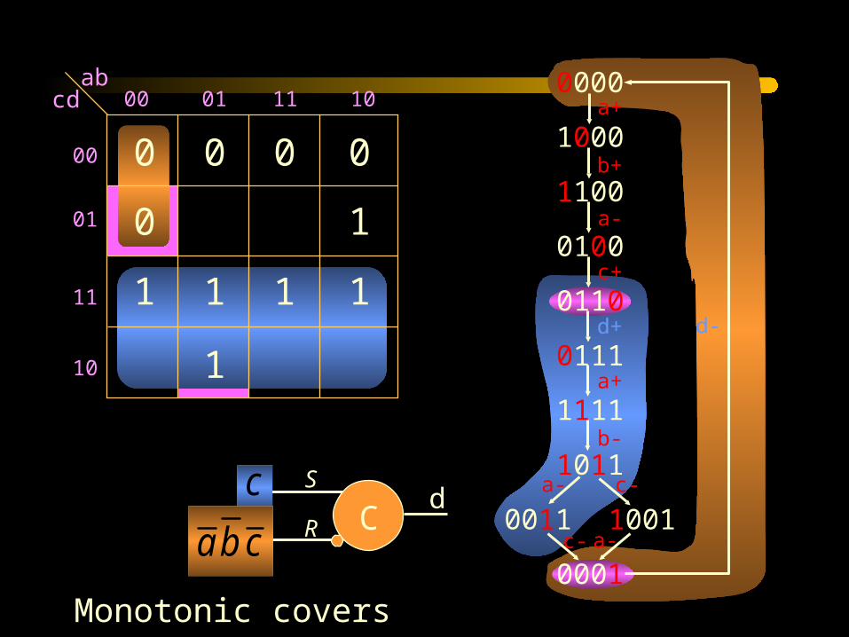
Complex gate

Implementation with C elements
CR
S z
• • • S+ z+ S- R+ z- R- • • •
• S (set) and R (reset) must be mutually exclusive
• S must cover ER(z+) and must not intersect ER(z-) QR(z-)
• R must cover ER(z-) and must not intersect ER(z+) QR(z+)

abcd 00 01 11 10
00
01
11
10 1
1 1 11
10
0 000
0000
1000
1100
0100
0110
0111
1111
1011
0011 1001
0001
a+
b+
c+
a-
b-
c-
a+
c-
a-
a-
d-d+
CS
Rdc
ca
abcd 00 01 11 10
00
01
11
10 1
1 1 11
10
0 000
0000
1000
1100
0100
0110
0111
1111
1011
0011 1001
0001
a+
b+
c+
a-
b-
c-
a+
c-
a-
a-
d-d+
CS
Rdc
cba
Monotonic covers

C-based implementations
CS
Rdc
cbaC
d
ab
c
a
b
cd
weak
a
cd
generalized C elements (gC)
weak

Speed-independent implementations
• Implementability conditions– Consistency– Complete state coding– Persistency
• Circuit architectures– Complex (hazard-free) gates– C elements with monotonic covers– ...

Synthesis exercise
y-
z- w-
y+ x+
z+
x-
w+
1011
0111
0011
1001
1000
1010
0001
0000 0101
0010 0100
0110
y-
y+
x-
x+w+
w-
z+
z-
w-
w-
z-
z-y+
y+
x+
x+
Derive circuits for signals x and z (complex gates and monotonic covers)

Synthesis exercise
1011
0111
0011
1001
1000
1010
0001
0000 0101
0010 0100
0110
y-
y+
x-
x+w+
w-
z+
z-
w-
w-
z-
z-y+
y+
x+
x+
wxyz 00 01 11 10
00
01
11
10
-
-
-
-
Signal x
1
0
1
1
1
1
1
0 0
0
0
0

Synthesis exercise
1011
0111
0011
1001
1000
1010
0001
0000 0101
0010 0100
0110
y-
y+
x-
x+w+
w-
z+
z-
w-
w-
z-
z-y+
y+
x+
x+
wxyz 00 01 11 10
00
01
11
10
-
-
-
-
Signal z
1
0 0
0
0
11 1
0
0 0
0
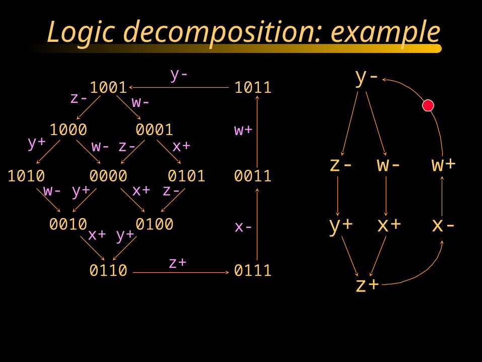
y-
z- w-
y+ x+
z+
x-
w+
1001 1011
1000
1010
0001
0000 0101
0010 0100
0110 0111
0011
y-
y+
x-
x+w+
w-
z+
z-
w-
w-
z-
z-y+
y+
x+
x+
Logic decomposition: example

yz=1yz=0
1001 1011
1000
1010
0001
0000 0101
0010 0100
0110 0111
0011
y-
y+
x-
x+w+
w-
z+
z-
w-
w-
z-
z-y+
y+
x+
x+
1001 1011
1000
1010
0001
0000 0101
0010 0100
0110 0111
0011
y-
y+
x-
x+w+
w-
z+
z-
w-
w-
z-
z-y+
y+
x+
x+
C
C
x
y
x
y
w
z
xyz
y
zw
z
w
z
y
Logic decomposition: example
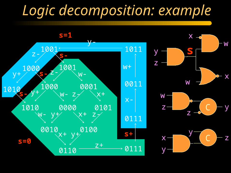
s-
s+
s-
s-
s=1
s=0
1001 1011
1000
1010
0111
0011y+
x-
w+
z+
z-
0001
0000 0101
0010 0100
0110
x+
w-
w-
w-
z-
z-y+
y+
x+
x+
1001
1000
1010
y+
z-
0111
C
C
x
y
x
y
w
z
x
y
z
w
z
w
z
y
sy-
Logic decomposition: example

y-
z- w-
y+ x+
z+
x-
w+
s-
s+
s-
s+
s-
s-
s=1
s=0
1001 1011
1000
1010
0111
0011y+
x-
w+
z+
z-
0001
0000 0101
0010 0100
0110
x+
w-
w-
w-
z-
z-y+
y+
x+
x+
1001
1000
1010
y+
z-
0111
y-
Logic decomposition: example

Speed-independent Netlist
LDS+ LDTACK+ D+ DTACK+ DSr- D-
DTACK-
LDS-LDTACK-
DSr+
DTACKD
DSr
LDS
LDTACK
csc
map

Adding timing assumptions
LDS+ LDTACK+ D+ DTACK+ DSr- D-
DTACK-
LDS-LDTACK-
DSr+
DTACKD
DSr
LDS
LDTACK
csc
map
LDTACK- before DSr+
FAST
SLOW

Adding timing assumptions
DTACKD
DSr
LDS
LDTACK
csc
map
LDS+ LDTACK+ D+ DTACK+ DSr- D-
DTACK-
LDS-LDTACK-
DSr+
LDTACK- before DSr+

State space domain
LDTACK- before DSr+
LDTACK-
DSr+

State space domain
LDTACK- before DSr+
LDTACK-
DSr+
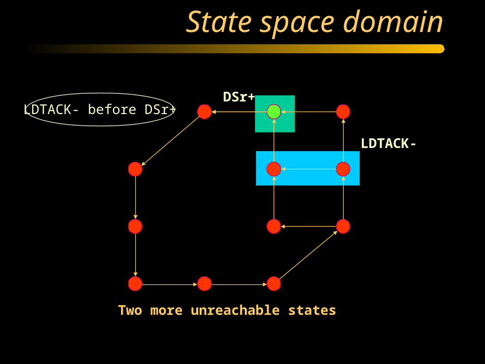
State space domain
LDTACK- before DSr+
LDTACK-
DSr+
Two more unreachable states

Boolean domain
DTACKDSrD
LDTACK 00 01 11 10
00
01
11
10
DTACKDSrD
LDTACK 00 01 11 10
00
01
11
10
LDS = 0 LDS = 1
0 1-0
0 0 0 0 0 0/1?
1
111
-
-
-
---
- - - -
-
- ---
- - -

Boolean domain
DTACKDSrD
LDTACK 00 01 11 10
00
01
11
10
DTACKDSrD
LDTACK 00 01 11 10
00
01
11
10
LDS = 0 LDS = 1
0 1-0
0 0 - 0 0 1
1
111
-
-
-
---
- - - -
-
- ---
- - -
One more DC vector for all signals One state conflict is removed

Netlist with one constraint
LDS+ LDTACK+ D+ DTACK+ DSr- D-
DTACK-
LDS-LDTACK-
DSr+
DTACKD
DSr
LDS
LDTACK
csc
map

Netlist with one constraint
LDS+ LDTACK+ D+ DTACK+ DSr- D-
DTACK-
LDS-LDTACK-
DSr+
DTACK D
DSr LDS
LDTACK
LDTACK- before DSr+
TIMING CONSTRAINT

Conclusions
• STGs have a high expressiveness power at a low level of granularity (similar to FSMs for synchronous systems)
• Synthesis from STGs can be fully automated
• Synthesis tools often suffer from the state explosion problem (symbolic techniques are used)
• The theory of logic synthesis from STGs can be found in:
J. Cortadella, M. Kishinevsky, A. Kondratyev, L. Lavagno and A. Yakovlev,J. Cortadella, M. Kishinevsky, A. Kondratyev, L. Lavagno and A. Yakovlev,Logic Synthesis of Asynchronous Controllers and InterfacesLogic Synthesis of Asynchronous Controllers and Interfaces ,,Springer Verlag, 2002.Springer Verlag, 2002.

Synthesis from asynchronous HDL
• CSP based languages
• CSP = communicating sequential processes [T. Hoare]
• Two synthesis techniques– based on program transformations [Caltech]– based on direct compilation [Philips]
• Complete shift in design methodology is required

Using CSP for control generation
• After li goes high do full handshake at the right, then complete handshake at the left and iterate.
li+ ro+ ri+ ro- ri- lo+ li- lo-
ro
ri
li
lo
Q element
*[[li];ro+;[ri];ro-;[not ri];lo+;[not li];lo-]
• “;” = sequencing operator• ro+ = ro goes high; ro- = ro goes low• [li] = wait until li is high; [not li] = wait until li is low
CSP:
STG:

Using CSP for control generation
*[[li];ro+;[ri];ro-;[not ri];lo+;[not li];lo-]
• Conflict: ro+ and ro- are not mutually exclusive• Eliminate conflict by state signal insertion (= CSC)
CSP:
Production rules:li -> ro+; ri -> ro-not ri -> lo+; not li -> lo-
ri
li
ro
weak

Conflict elimination
*[[li];ro+;[ri];x+;[x];ro-;[not ri];lo+;[not li];x-;[not x];lo-]CSP:
Production rules:not x and li -> ro+; x or not li -> ro-x and not ri -> lo+; not x or ri -> lo-ri -> x+; not li -> x-
FFx not x
li
lo ri
ro

Conclusions
• Generating circuits from CSP control program is similar to STG synthesis
• One can be reduced to the other
• Particular technique may vary. Direct CSP program transformations can be (and were) used instead of methods based on state space generation
• See reference list for more details

Buffer example in Tangram
(a?byte & b!byte)begin
x0: var byte | forever do
a?x0 ; b!x0od
end
Buffer
*
xa bT
;
T
a b
passive port
active port Each circle mapped to a netlist
Data path
Q element
Summary
• Tangram program is partitioned into data path and control
• Data path is implemented as dual or single rail
• Control is mapped to composition of standard elements (“;” “||” etc)
• Each standard element is mapped to a circuit
• Post-optimization is done
• Composing islands of control elements and re-synthesis with STG can give more aggressive optimization
• Philips made a few chips using Tangram, including a product: 8051 micro-controller in low-power pager Muna (25 wks battery life from one AAA battery)
• Public domain Tangram compiler is available (Balsa, U. Manchester)

Burst mode FSM
s1
s2
s3
s4
b-/x-a+b+/y+
a-/x+y-
c+/y-c-/y+
• Close to synchronous FSMs with binary encoded I/O
• Work in bursts:– Input transitions fire
– Output transitions fire
– State signals change
• Mostly limited to fundamental mode: next input burst cannot arrive before stabilization at the outputs

Extended Burst mode
s1
s2
s3
s4
b-/x-
a+b*/y+<b+>a-/x+y-
<b+>c+/y-c-/y+
• Directed don’t cares (b*): some concurrency is allowed for input transitions that do not influence an output burst
• Conditional guards <b+> = “if b=1 then …”

Synthesis of XBM
• Next state and output functions free of functional and logic hazards
• Sequential feedbacks should not introduce new hazards
• State assignment– one state of the BM spec to one layer of Karnaugh map
– compatible layers are merged
– layers are compatible if merging does not introduce CSC violations or hazards
– Layers are encoded using race free encoding

XBM and STG
s1
s2
s3
s4
b-/x-
a+b*/y+<b+>a-/x+y-
<b+>c+/y-c-/y+
x-
a+
y+
b+
eps
c-
a- c+
y-
y+
x+ y-
b-

Summary
• Specification: XBM is subclass of STGs
• Synthesis: techniques are extensions of synchronous state assignment and logic minimization
• Timing:
– environment is limited to fundamental mode (difficult for pipelined and highly concurrent systems)
– internals are delay insensitive
• See reference list for details