bridge manoeuvring system - praxis · pdf filebridge manoeuvring system ... takes place via...
TRANSCRIPT
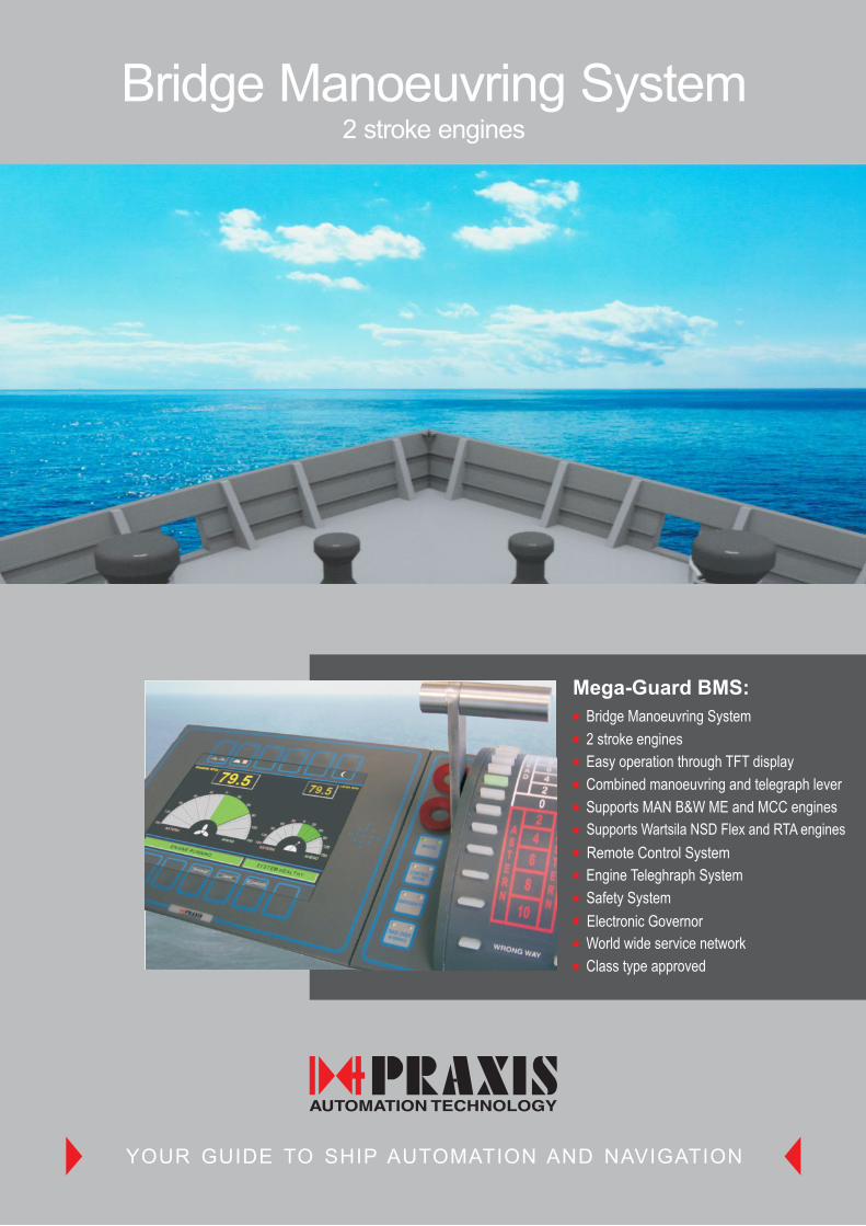
Bridge Manoeuvring System
Mega-Guard BMS:
Bridge Manoeuvring System
2 stroke engines
Easy operation through TFT display
Combined manoeuvring and telegraph lever
Supports MAN B&W ME and MCC engines
Supports Wartsila NSD Flex and RTA engines
Remote Control System
Engine Teleghraph System
Safety System
Electronic Governor
World wide service network
Class type approved
YOUR GUIDE TO SHIP AUTOMATION AND NAVIGATION
2 stroke engines

2
Br i d g e Ma n o e u v r i n g Sys te m
BM
S C
on
trol P
roce
sso
r with
1 I/O
Mo
du
leB
MS
Bridge C
ontr
ol,
Leve
r &
Tele
gra
ph O
pera
tor
Panel
C
B
A
C
B
A
C
B
A
C
B
A
C
B
A
C
B
A
C
B
A
C
B
A
9
11
12
10
13
15
16
14
Part No.: 98.6.034.702 I/O BOARD ID.: 203
MAIN STARTVALVE
IN SERVICE
MAIN STARTVALVE
BLOCKED
MAIN STARTVALVEFWE
START AIRDISTR. BLOCKED
TURNING GEARENGAGED
TURNING GEARDISENGAGED
GOVERNORENGAGED S6
EMERGENCYCONTROL P2
STARTING AIRPRESSURE
FUEL CUTSIGNAL ACTIVE
CONTROL AIRFWE
RESET INEMERGENCY POS.
SAFETY AIRPRESSURE
AUX BLOWERRUNNING
EMERGENCYCONTROL P2
AUX BLOWERSTOP
C
B
A
C
B
A
C
B
A
C
B
A
C
B
A
C
B
A
C
B
A
C
B
A
1
3
4
2
5
7
8
6
I/O BOARD FAILURESYSTEM ON
AUTOMATION TECHNOLOGY
CONTROLPROCESSOR
Graphic
13
17
21
15
19
23
14
18
22
16
20
24
1
5
9
3
7
11
2
6
10
4
8
12
System Lay-out
The Mega-Guard Bridge Manoeuvring System is built-up with the followingindependent systems:
Remote Control System Engine Telegraph System Safety System Speed Controller
Each independent system is built-up with the same hardware and softwarecomponents in order to minimize the number of different spare parts.The independent systems communicate with each other via the Fieldbusnetwork (main/backup). The redundant Fieldbus can be delivered in Ethernetor CAN-Bus technology. Communication to other systems, such as ship's alarmand monitoring system, takes place via hard-wired signals or serial link. A seriallink interface is provided to record all events to the Voyage Data Recorder.
Advanced Control Processors equipped with I/O Modules are used in eachindependent system. Sensors and actuators are directly wired to the I/O Moduleswhich are mounted on a DIN rail.
0
2
4
AHEAD
AHEAD
8
6
10
TAKE OVER SYSTEM ONIN SERVICE LAMP TEST
AT SEALOCAL
FWEBRIDGE
STANDBYCONTROL
ROOM
2ASTERN
ASTERN
4
8
6
10
WRONG WAY
AUTOMATION TECHNOLOGY
AUTOMATION TECHNOLOGY
Features
The Mega-Guard Bridge Manoeuvring System fully automates the remote control of the propulsion engine from the bridge andcontrol room. All functions of main engine remote control as required by 2 stroke engine manufacturers MAN B&W (ME andMCC Engines) and Wärtsila NSD (Flex and RTA Engines) are executed by the Mega-Guard BMS.
The reliable Operator Panels on the Bridge, the Control Room and on the Local EmergencyStand are easy to operate and to install. The remote control system receives orders from thecombined manoeuvring / telegraph lever on the Bridge or Control Room. The remote controlsystem activates starting, stopping and reversing mechanism on the engine and gives aSpeed Setpoint to the Electronic Governor.

3
E l e c t r o n i c Go ve rn o r
Operator Panels
ER
Lo
ca
l Co
ntro
l Ca
bin
et
Operator Panels are connected via dedicated cables to the
Control Processors. The following Operator Panels are available:
The Bridge and CR Operator Panel are equipped with a 7" TFT
color graphic screen which can be operated via easy to use soft keys.
Bridge Control, Lever and Telegraph Operator Panel
Bridge Wing Operator Panel
CR Control, Lever and Telegraph Operator Panel
CR Back-up Operator Panel
ER Telegraph Operator Panel
BM
S C
R C
ontro
l, Leve
r & Te
legra
ph O
pera
tor P
anel
0
2
4
AHEAD
AHEAD
8
6
10
TAKE OVER SYSTEM ONIN SERVICE LAMP TEST
AT SEALOCAL
FWEBRIDGE
STANDBYCONTROL
ROOM
2ASTERN
ASTERN
4
8
6
10
WRONG WAY
AUTOMATION TECHNOLOGY
AUTOMATION TECHNOLOGY
Speed Controller (MCC and RTA)
The highly reliable Speed Controller controls the speed of the main engine by adjusting the fuel rack.The Electronic Governor consists of an Electric Actuator with Electronic Drive Unit and a Speed Controller. The Governoris operated via the CR Operator Panel in the control room console. The Speed Controller uses advanced control algorithmsin order to control engine speed. The Electronic Governor requires no maintenance and makes use of a brush-lessAC servo-motor. Three different sizes are available for engines with cylinder bores ranging from 40 to 120mm.The Electronic Governor provides accurate speed control of the main engine; even in heavy conditions like rough weather,wind-milling, minimum speed and failure of one cylinder.

Mega-Guard Bridge Manoeuvring System
YOUR GUIDE TO SHIP AUTOMATION AND NAVIGATION
Praxis Automation China
Praxis Automation Korea
Praxis Automation Singapore
Praxis Automation India
Your representative:Branch offices:
Praxis Automation Technology B.V.Zijldijk 24A, 2352 AB Leiderdorp, The Netherlands
+31 (0)71 5255 353 +31 (0)71 5224 [email protected]
www.praxis-automation.com
Mega-Guard Ship Automation and Navigation System
DynamicPositioning System
PropulsionControl System
EconometerSystem
PowerManagement System
Valve Control andMonitoring System
HeadingControl System
BNWASWatch Alarm System
FireAlarm System
Alarm andMonitoring System
Navigation Light andWindow Wiper System
IntegratedBridge System
Alarm Monitoringand Control System
En
gin
e R
oo
mB
rid
ge
Co
ntr
ol R
oo
m C
on
sole
Bridge Control Lever &Telegraph Operator Panel
RPM WingIndicator
RPM WingIndicator
RPMIndicator
RPMModule
RPMIndicator
CR Control Lever &Telegraph Operator Panel
RPMIndicator
Engine Electronic Boxes
Main Engine
RPM Detector Boxes
Electric Actuator(MC+RTU)
(Not Praxis Supply)
SIZE SCALE
Remote Control/SafetyConnection Plate
Speed ControllerConnection Plate
To ship'salarm system
To Alarm & Monitoring System
Fieldbus (Main/Backup)
Fieldbus (Main/Backup)
Fieldbus (Main/Backup)
Multicore Cable
Multicore CableMulticore Cable
Em
erg
ency
Sto
pM
ulti
core
Cable
Multicore CableMulticore CableMulticore Cable
Multicore Cable
Fieldbus (Main/Backup)
Fieldbus (Main/Backup)
To VDR
Back-upOperator Panel
Local Control Cabinet
Fuel PumpMark Ind.
AHEAD
0
150
50
100
50
100
150
RPM
ASTERN
50
100
150
AHEAD
0
150
50
100
50
100
150
RPM
ASTERNAHEAD
0
150
50
100
50
100
150
RPM
ASTERN
C
B
A
C
B
A
C
B
A
C
B
A
C
B
A
C
B
A
C
B
A
C
B
A
9
11
12
10
13
15
16
14
C
B
A
C
B
A
C
B
A
C
B
A
C
B
A
C
B
A
C
B
A
C
B
A
1
3
4
2
5
7
8
6
C
B
A
C
B
A
C
B
A
C
B
A
C
B
A
C
B
A
C
B
A
C
B
A
9
11
12
10
13
15
16
14
C
B
A
C
B
A
C
B
A
C
B
A
C
B
A
C
B
A
C
B
A
C
B
A
1
3
4
2
5
7
8
6
13
17
21
15
19
23
14
18
22
16
20
24
1
5
9
3
7
11
2
6
10
4
8
12
I/O BOARD FAILURE
6049 PROCESSOR BOARD
SYSTEM ON
AUTOMATION TECHNOLOGY
0
2
4
AHEAD
AHEAD
8
6
10
TAKE OVER SYSTEM ONIN SERVICE LAMP TEST
AT SEALOCAL
FWEBRIDGE
STANDBYCONTROL
ROOM
2ASTERN
ASTERN
4
8
6
10
WRONG WAYAUTOMATION TECHNOLOGY
AUTOMATION TECHNOLOGY
AUTOMATION TECHNOLOGY
AHEAD
0
150
50
100
50
100
150
RPM
ASTERN AHEAD
0
150
50
100
50
100
150
RPM
ASTERN
0
2
4
AHEAD
AHEAD
8
6
10
TAKE OVER SYSTEM ONIN SERVICE LAMP TEST
AT SEALOCAL
FWEBRIDGE
STANDBYCONTROL
ROOM
2ASTERN
ASTERN
4
8
6
10
WRONG WAYAUTOMATION TECHNOLOGY
AUTOMATION TECHNOLOGY
C
B
A
C
B
A
C
B
A
C
B
A
C
B
A
C
B
A
C
B
A
C
B
A
9
11
12
10
13
15
16
14
C
B
A
C
B
A
C
B
A
C
B
A
C
B
A
C
B
A
C
B
A
C
B
A
1
3
4
2
5
7
8
6
C
B
A
C
B
A
C
B
A
C
B
A
C
B
A
C
B
A
C
B
A
C
B
A
9
11
12
10
13
15
16
14
C
B
A
C
B
A
C
B
A
C
B
A
C
B
A
C
B
A
C
B
A
C
B
A
1
3
4
2
5
7
8
6
13
17
21
15
19
23
14
18
22
16
20
24
1
5
9
3
7
11
2
6
10
4
8
12
I/O BOARD FAILURE
6049 PROCESSOR BOARD
SYSTEM ON
AUTOMATION TECHNOLOGY
C
B
A
C
B
A
C
B
A
C
B
A
C
B
A
C
B
A
C
B
A
C
B
A
9
11
12
10
13
15
16
14
C
B
A
C
B
A
C
B
A
C
B
A
C
B
A
C
B
A
C
B
A
C
B
A
1
3
4
2
5
7
8
6
C
B
A
C
B
A
C
B
A
C
B
A
C
B
A
C
B
A
C
B
A
C
B
A
9
11
12
10
13
15
16
14
C
B
A
C
B
A
C
B
A
C
B
A
C
B
A
C
B
A
C
B
A
C
B
A
1
3
4
2
5
7
8
6
13
17
21
15
19
23
14
18
22
16
20
24
1
5
9
3
7
11
2
6
10
4
8
12
I/O BOARD FAILURE
6049 PROCESSOR BOARD
SYSTEM ON
AUTOMATION TECHNOLOGY
13
17
21
15
19
23
14
18
22
16
20
24
1
5
9
3
7
11
2
6
10
4
8
12
I/O BOARD FAILURE
6049 PROCESSOR BOARD
SYSTEM ON
AUTOMATION TECHNOLOGY
8
12
15
RJ45
BACKUPLINK
ETHER-NET
10
14
17
9
13
16
11
1
3
2
4
I/O BOARD FAILURESYSTEM ON
AUTOMATION TECHNOLOGY
CONTROLPROCESSOR
Ethernet & GraphicRJ45
MAINLINK
ETHER-NET
Redundant Fieldbusdelivered in Ethernetor CAN-Bus technology
TelegraphGong
EMER
GENCY
SLO
W
FULL
SLOWHALF
BRIDGE
SLOW
NAVIGATIONFULL FULL
ER
N
A
ST
DH
AE
A
FULL
HALF
SLO
W
DEA
D
S
POT
DEA
D
C/R LOCAL
RUN UP
STANDBY
FWE
TELEGRAPH FAILURE
WRONG WAY
NEW COMMAND
REPLY
AUTOMATION TECHNOLOGY
PS
Win
g
Wh
eel H
ou
se
SB
Win
g
Fro
nt
Co
nso
leIn
sid
e C
on
sole