bridge erection techniques and their influence on permanent designs
TRANSCRIPT

‘Bridge Erection Techniques – and – their Influence on the Permanent Designs’ – Er. V. G. Abhyankar
National workshop at COEP, Pune on “Innovation in Bridge Engineering” – 15-16
th Oct’2011
Under (Late) Shri S. B. Joshi Memorial Activity
Page - 1 of 9
Bridge Erection Techniques and their influence
on Permanent Designs
Paper by – Er. Vivek G. Abhyankar – C.Eng.
�थाप�य तथा वा�तुअ�भयंता Mumbai
Abstract :
Bridge engineering has significantly grown-up in past 50 years because of the increasing
infrastructure demands and the developments in other peripheral branches of engineering. Many
new complex bridges are coming up in reality, now. But this has resulted into a few problem areas
also. Unlike in past, the development that is taking place today, in the design of bridges, is not going
hand-in-hand with the Construction (Execution) technology (especially in developing countries like
India). In fact, in most of the modern bridges it is observed that unless the Construction methods are
excelled, there is no point in adopting any modern theory / software in the bridge design. The
increasing infrastructure demands necessitate faster, safer, economical, yet superior quality of
erection of bridge superstructure. In certain cases, the modern bridge erection technology imposes
significantly larger loads than the design loads. On the other hand, the construction methodology
has to confirm the design requirements.
In the present paper the author has attempted to present the linkage between the Bridge
erection technology and the Permanent design of bridges with certain live case studies.
Key Words :
Enabling works, Permanent Works, Bridge Super structure, Arch Bridge, Segmental Construction, Launching Girder,
Floating Crane, Cantilever form traveller (CFT), Moving scaffolding system (MSS), Construction stage analysis,
Construction loading, stability, Curved Girders, HSE, Santiago Calatrava, Firth of Forth Bridge, Steel Arch,
Cantilever Bridge, Secondary Stresses, Cable Crane (Cable way), JV
Introduction :
Bridges are the backbones of any Transpiration / Infrastructure Project (Railway / Road).
Bridge Engineering has a history of thousands of years, and finds it’s origin in Indian Mythology
and spiritual scripts like Ramayana / Mahabharata. In those days bridges made of hip of stone blocks
/ bunds / timber logs were the only options possible. The old bridges were expected to merely act as
a beam spanning across the gaps along the road / railway alignments. But as the growth of
civilisation (society / cultural development) started taking place, the demand on all the branches of
engineering (industry) increased by exponentially. The increased demand called for more and more
research that started taking place. From study of engineering growth in last hundred years, we may
observe that the development of Civil / Structural engineering is closely associated with the
developments that took place in the peripheral branches like – Material Science, Mathematics,
Communication, Electronics, Computing technology (computer science), IT, and the Newly
emerging branches of engineering.
As all the branches of engineering started growing, it was observed that the growth was rapid, but
not parallel! This fact resulted into a serious problem – or a gap between imagination (Conceptual

‘Bridge Erection Techniques – and – their Influence on the Permanent Designs’ – Er. V. G. Abhyankar
National workshop at COEP, Pune on “Innovation in Bridge Engineering” – 15-16
th Oct’2011
Under (Late) Shri S. B. Joshi Memorial Activity
Page - 2 of 9
planning / Design) and the ground-reality (i.e. actual bridge erected at sites). The end results of this
gap (rather a knowledge gap) and the solution to ‘bridge’ this gap is discussed in the further sections.
Bridge Projects in Olden days :
In olden days the computing technology / simulation software etc. were not available. Engineers had
to struggle hard to prove the adequacy of the concept, before starting the design and construction.
Fig.1 shows, photograph of ‘Firth of Forth Bridge, Scotland’, which is a steel cantilever bridge. It
was built in the 1880s by Allan Stewart and Sir Benjamin Baker. But both of them had to struggle
hard to demonstrate by a Conceptual Model (as shown in Fig.1 below) to the sceptical Victorians
that a cantilever bridge would be safe. Fig. 1 also shows the actual bridge after construction.
Fig.1 – Firth of Forth Bridge, Scotland (A Cantilever Bridge)
Designed by Allen Stewart and Sir Baker
Similar to above bridge Fig.2 shows another interesting configuration of a Suspension cable bridge
done out of India. In this structure the main pylons look like a posture of a standing person, reclining
back slightly, with both the arms folded, kept on waist.
Fig.2 – Another innovative bridge which had abutments like a racking human body
Introduction to New Types of Bridges : A Challenges for Designers :
Unlike 50 / 60 years back, the computing technology, materials sciences have lead to converting
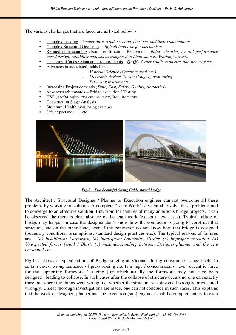
even the complex shaped bridges in the reality. Fig.3 shows two a beautiful String Cable stayed
bridge designed by Famous Architect and Structural Engineer Santiago Calatrava. During
conceptual planning and the design of such modern bridges, often various challenges are faced. A
few of these challenges are as listed ahead.
‘Bridge Erection Techniques – and – their Influence on the Permanent Designs’ – Er. V. G. Abhyankar
National workshop at COEP, Pune on “Innovation in Bridge Engineering” – 15-16
th Oct’2011
Under (Late) Shri S. B. Joshi Memorial Activity
Page - 3 of 9
The various challenges that are faced are as listed below :-
• Complex Loading – temperature, wind, erection, blast etc. and their combinations
• Complex Structural Geometry – difficult load transfer mechanism
• Refined understanding about the Structural Behaviour – failure theories, overall performance
based design, reliability analysis as compared to Limit state vs. Working stresses
• Changing ‘Codes / Standards’ requirements – QAQC, Crack width, exposure, non-linearity etc.
• Advances in associated fields like :-
– Material Science (Concrete-steel-etc.)
– Electronic devices (Strain Gauges), monitoring
– Surveying Instruments
• Increasing Project demands (Time, Cost, Safety, Quality, Aesthetics)
• New research towards – Bridge execution / Testing
• HSE (health safety and environment) Requirements
• Construction Stage Analysis
• Structural Health monitoring systems
• Life expectancy . . . etc.
Fig.3 – Two beautiful String Cable stayed bridge
The Architect / Structural Designer / Planner or Execution engineer can not overcome all these
problems by working in isolation. A complete ‘Team Work’ is essential to solve these problems and
to converge to an effective solution. But, from the failures of many ambitious bridge projects, it can
be observed the there is clear absence of the team work (except a few cases). Typical failure of
bridge may happen in case the designer don’t know how the contractor is going to construct that
structure, and on the other hand, even if the contractor do not know how that bridge is designed
(boundary conditions, assumptions, standard design practices etc.). The typical reasons of failures
are – (a) Insufficient Formwork, (b) Inadequate Launching Girder, (c) Improper execution, (d)
Unexpected forces (wind / Blast) (e) misunderstanding between Designer-planner and the site
personnel etc.
Fig.11.a shows a typical failure of Bridge staging at Vietnam during construction stage itself. In
certain cases, wrong sequence of pre-stressing exerts a huge / concentrated or even eccentric force
for the supporting formwork / staging (for which usually the formwork may not have been
designed), leading to collapse. In such cases after the collapse of structure occurs no one can exactly
trace out where the things went wrong, i.e. whether the structure was designed wrongly or executed
wrongly. Unless thorough investigations are made, one can not conclude in such cases. This explains
that the work of designer, planner and the execution (site) engineer shall be complementary to each

‘Bridge Erection Techniques – and – their Influence on the Permanent Designs’ – Er. V. G. Abhyankar
National workshop at COEP, Pune on “Innovation in Bridge Engineering” – 15-16
th Oct’2011
Under (Late) Shri S. B. Joshi Memorial Activity
Page - 4 of 9
other and not the contradictory. Thus each one of them must know the works of others (their
counter-parts) to a sufficient extent.
Introduction to various Bridge Erection Techniques : A Challenges for Execution
From the above discussion it is clear that the complexity in Bridge Engineering is increasing, which
can not be handled alone by the bridge designer or site engineer. The Designer must know the
proposed method, which the contractor wants to employ for the construction site of the said bridge;
and on the other hand the execution person and planner must know briefly, how the designer has
designed the structure, with its Limiting conditions / Boundary Conditions / Assumptions. In certain
cases, the execution of design, as it is, become difficult due to site specific conditions (probably,
which could not have been addressed by the Structural Engineer at design stage). In such cases the
modification in design becomes necessary. If the contactor knows the design basis, he can develop a
better proposal indicating desired changes in design at a particular spot in the project. (On the other
hand even, if the designer knows the constraints at site, in which the site engineer is supposed to
work, he can develop better design, right from construction stage).
A few of the popular methods adopted for construction of bridge super structure are as listed ahead :-
• Erection using Traditional Methods
– Using Formwork
– With land based hydraulic cranes (single / double cranes – for (i) span-by-span
construction or even (ii) random span construction
• Erection using Modern Methods
– Floating Cranes / Barges / Jack-up platforms
– Using Bridge Launching Girders
– Cable Cranes
– CFT (Cantilever Form Traveler) / MSS (Moving Scaffolding System)
– Tower Carnes
Bridge erection using a Floating Crane :
In case of long span bridges, Launching
Girder (LG) is commonly used by the
contractors (ref. Fig.6 and Fig.7, which
shows a typical Truss type Bridge
Erection Launcher, used at Bang-Na-
Trade Highway Project, Bangkok). But
if the bridge is passing over a large water
body it is convenient to use floating
cranes kept on the Barges / vessels /
jack-up platforms. Fig.4 shows such
typical floating crane (and Fig.5 shows
bridge erection using a single land based
crane in segmental bridge). But during
use of such methodology there are points
to ponder as listed ahead.
Fig.4 – Showing A typical floating Bridge erection Crane

‘Bridge Erection Techniques – and – their Influence on the Permanent Designs’ – Er. V. G. Abhyankar
National workshop at COEP, Pune on “Innovation in Bridge Engineering” – 15-16
th Oct’2011
Under (Late) Shri S. B. Joshi Memorial Activity
Page - 5 of 9
Fig.5 –Bridge erection with single
Land based Crane
Points to Ponder :
1) Duration of Project
2) Capacity of Floating Cart
3) Availability and Characteristics of water way
4) Facts of actual Site :
• Casting Yard location
• Wind Speed
• Tidal variations
5) Cost / Budget
6) Cooperation from Designers / Design capacity
Bridge erection using a Launching Girder :
From Fig.7, which is showing Bridge Erection Launcher,
used in Bangkok, it may be seen that the Permanent structure
has good Aesthetic look, which is not only utilized by the
execution engineer to place the LG, but also the impact of
LG on the permanent structure. Also, from Fig.8, one may
observe the necessity of stability of erection system during
girder erection. Faulty system may lead to incorrect bridge geometry or even accumulation of
secondary stresses in the girder body /distortion. Apart from these, there could be accidents leading
to damage to structure or human life (as shown in Fig. 10, 11).
Fig.6 – Showing Schematic Diagram of Bridge launcher
Apart from the regular bridge erection techniques like Formwork / Staging, Launching Girders and
advanced technique of Floating Cranes, A suspended erection crane / cableway is also used now
days as shown in Fig. 9, for a steel Arch Segmental Bridge in China. In such cases the Permanent
structure has to be designed keeping in mind the construction / erection and dismantling
methodology. The construction scheme / methodology imposes large loads on the permanent
structure, which are often greater than the Design loads even (i.e. critical combination of self wt,
Live load, wind / earthquake etc.).
Bridge erection using a suspended Cable Crane (cableway) :
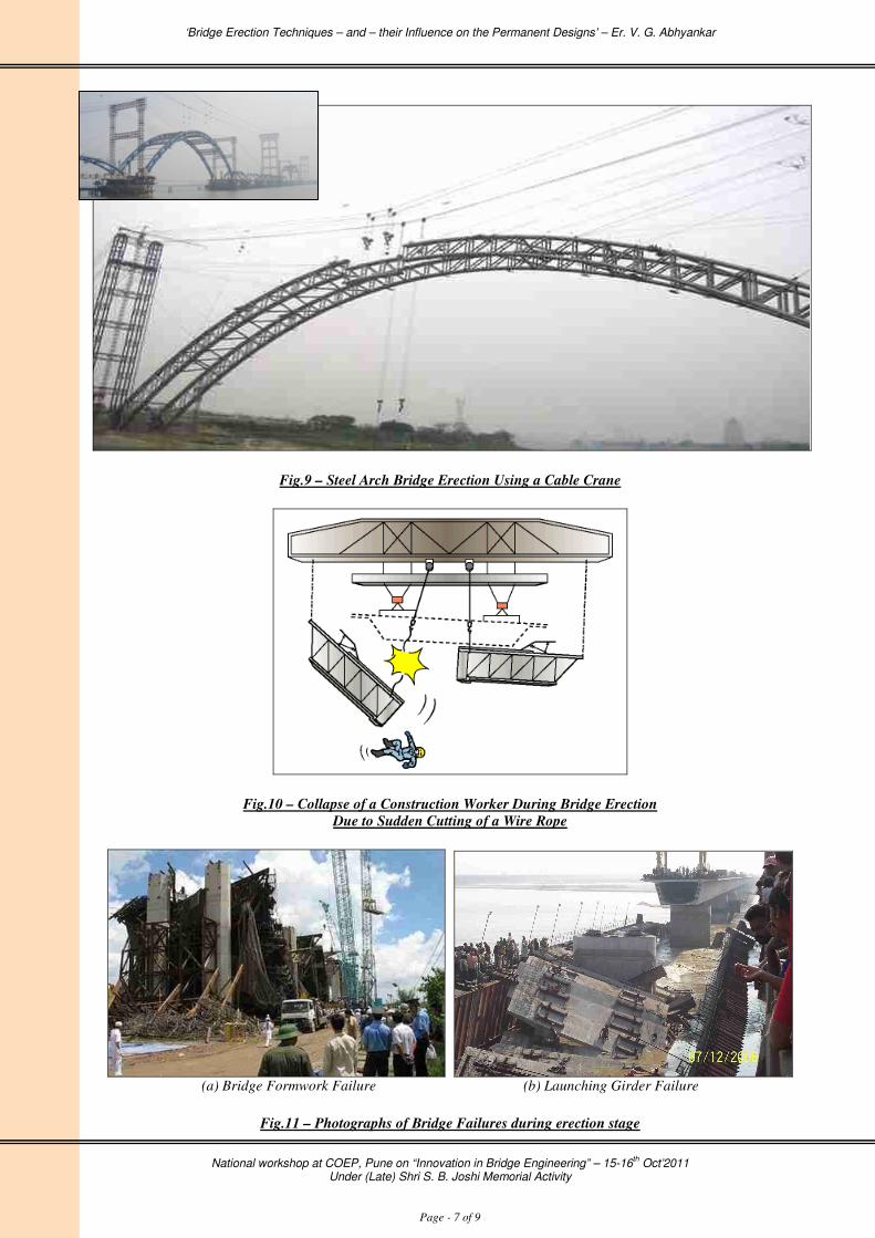
This is unique and challenging technique of bridge construction. Fig.9 a photograph of steel
segmental arch bridge construction, in China, using cable crane (or alternatively called as a cable
way). In Indian on Chenab river bridge project similar technique is planned to be used. Cableway is
also- being used on the Concrete Arch Bridge at world famous Hoover dam. In this case the design
and – construction must go hand-in-hand to reach to successful conclusion. Issues like tension in the

‘Bridge Erection Techniques – and – their Influence on the Permanent Designs’ – Er. V. G. Abhyankar
National workshop at COEP, Pune on “Innovation in Bridge Engineering” – 15-16
th Oct’2011
Under (Late) Shri S. B. Joshi Memorial Activity
Page - 6 of 9
cable, wind velocity for the stability of ropes under self wt and lifted wt condition (i.e. operating and
idling conditions), safety from falling objects at night, anything being hit to the cable etc. are the
critical issues in such method. These issues must be addressed prior to the start of design (at
conceptual stage itself).
Fig.7 – Bridge Erection Launcher, used at Bang-Na-Trade Highway Project, Bangkok
Fig.8 – Bridge Erection Launcher, used at Bang-Na-Trade Highway Project, Bangkok
‘Bridge Erection Techniques – and – their Influence on the Permanent Designs’ – Er. V. G. Abhyankar
National workshop at COEP, Pune on “Innovation in Bridge Engineering” – 15-16
th Oct’2011
Under (Late) Shri S. B. Joshi Memorial Activity
Page - 7 of 9
Fig.9 – Steel Arch Bridge Erection Using a Cable Crane
Fig.10 – Collapse of a Construction Worker During Bridge Erection
Due to Sudden Cutting of a Wire Rope
(a) Bridge Formwork Failure (b) Launching Girder Failure
Fig.11 – Photographs of Bridge Failures during erection stage

‘Bridge Erection Techniques – and – their Influence on the Permanent Designs’ – Er. V. G. Abhyankar
National workshop at COEP, Pune on “Innovation in Bridge Engineering” – 15-16
th Oct’2011
Under (Late) Shri S. B. Joshi Memorial Activity
Page - 8 of 9
As mentioned earlier there are many innovative methods like CFT / MSS / erection using tower
crane. They can be used only if there is close interaction between the designs – detailer – contractor
is established.
Conclusions
From the discussion till now it may be clear that the permanent design and erection method
(enabling works) have very close relation to each other. Following are some of the projects where
the permanents designs and enabling works have affected each other :-
• Permanent Design affecting the Enabling Works
a) Allahabad-Nainy Cable Stayed bridge project :
This project was done by Joint venture (JV) of HCC and Hyundai. In this project almost 20m
wide bridge deck was supported with 1400mm wide and 3500mm deep two Pre-stressed
rectangular girders (which were monolithically cast with the deck slab). Each span was 60m
long. There were 4 modules to be cast. The longest module has nine continuous pres-stressed
spans. Every 60m span was cast along with the 1/5th
(i.e. 12m) of next span i.e. at theoretical
point of contra flexure.
During the application of pre-stress as the 60m portion of the girder used to get ‘hogged–up’,
the remaining 12m portion used to get dipped-down, because of the continuity in the
construction, This resulted into enormous increase in the load on the formwork / staging in
the 12m portion (which was temporarily acting as cantilever, till the remaining 48m was cast
in next pour). This effect was predetermined and the Formwork and Staging was designed
accordingly. Also the pre-camber was pre-determined and set in the staging during erection
work.
b) Koaldam hydro electric project, (Himachal Pradesh) :-
In this project the De-silting chamber was to be construed. The RCC I Girders, were to be
cast on the top of De-silting chamber at height of 50m above the ground (where wind speed
is beyond imagination). Even the tower carne available was having a limited load lifting
capacity (5Mt at 20m radius). Hence the centering steel trusses (to cast the girder) were
spliced in three parts (to reduce self wt below 5Mt), and these Steel-centering-trusses were
supported on the piers. While dismantling they were suspended from the set girder during
lowering operation. The holes for suspension wire were left-out after discussion with the
designer.
• Enabling works affecting the Permanent Design
a) Longest Railway Bridge at Cochin for RVNL :-
In this project Rail Vikas Nigam Limited (RVNL) had initially proposed a 600Mt single box
girder per span. But as the SBC of soil at casting yard was very less, the contractor proposed
Two-Pre-stressed concrete I girders at each span. This Modification of Bridge Super
Structure considering the Limitations of Soil Bearing Capacity in casting yard, Time Cycle
and the possible erection methodology (NRS Launching girder) was readily approved by the
client. The project was completed ahead of the schedule, within the budgeted cost. This

‘Bridge Erection Techniques – and – their Influence on the Permanent Designs’ – Er. V. G. Abhyankar
National workshop at COEP, Pune on “Innovation in Bridge Engineering” – 15-16
th Oct’2011
Under (Late) Shri S. B. Joshi Memorial Activity
Page - 9 of 9
example describes how the enabling works forced to modify the permanent structure, yet
leading to ultimate success of the project.
b) DMRC project :–
In this project the LG threw more reaction (Shear force and bending moments, both) on the
Girder, which was more than the Design value. This was pre-estimated at design stage itself
by the close interaction between client, consultant and the contactor. Even at one place as the
load on pier due to LG was more than the design load at later stage the design had to be
modified.
Let’s hope that all these projects, and the discussion above is eye-openers to all the stakeholders
(Client, Designer, PMC, Planner, QAQC, Site Engineer) involved in the execution of bridge
superstructure. If practiced sincerely, this will be definitely lead to better infrastructure for our
society.
Acknowledgement & References :
The author is thankful to the Afcons Infrastructure Limited and entire site team for making all the
relevant data available for this paper. The thanks go to organiser of the National Workshop, COEP.
Alumni, also for considering this paper in this bulletin. All the references mentioned here are purely
from academic interest and there is no purpose to promote anything, directly or indirectly or to
accuse anyone.
In addition to the present Paper following papers may be referred for more information :-
a) “Nad-al-Sheba Race Course Development Project : Construction of three Bridges” – author
V. G. Abhyankar – published as Cover Story in quarterly journal of Indian Society of
Structural Engineers (ISSE), Mumbai, Vol-13/2, April-May-June’2011 issue.
b) “Construction Longest Railway Bridge Project at Cochin” – author V. G. Abhyankar –
published as Cover Story in quarterly journal of Indian Society of Structural Engineers
(ISSE), Mumbai, Volume 11-3, Jul-Aug-Sep
c) Various posts / articles published by the Author on Structural Engineers Form (Sefi) and
Linked-In.
d) Other Various websites / projects, mentioned below the respective photo / locations.
About Author:
Er. Vivek G. Abhyankar – C.Eng, Sr. Manger (Design), AFCONS
Infrastructure limited, has more than thirteen years of experience in planning
and design, detailing of various enabling and permanent works in Reinforced
concrete and Steel. The Author himself was deputed at the Project site
described in the present papers to handle all the technical matters. The author
has written many papers on Civil / Structural engineering aspects and also has
proof checked a book on earthquake engineering.
(email – [email protected])
* * *