bplt15bscr and bplt15bscr-b battery operated hydraulic
TRANSCRIPT

IMPORTANT: Read and understand all of the instructions and safety information in this manual before operating or servicing this tool.
BPLT15BSCR and BPLT15BSCR-BBattery Operated Hydraulic Crimping Tool
Operating Instruction Manual
1.0 General Characteristics 22.0 Instructions for Use 33.0 Battery Use 44.0 Maintenance 45.0 Spare Parts List 5&66.0 Optional Accessories 7
Table of Contents
TA03982 D Page 1 of 7
5 6 71 2 4 4Ni-MH
3
28
34
26
27
27
1918
25
1.0 GENERAL CHARACTERISTICS
BATTERY OPERATED HYDRAULIC CRIMPING TOOL
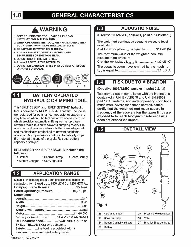
This “BPLT15BSCR” and “BPLT15BSCR-B” hydraulic tool is powered by 14 4 V DC Ni-MH battery The tool is well balanced for optimum control, quiet operation and very little vibration The tool has a two speed operation which provides automatic shifting from a rapid ram advance mode to a slow powerful crimping mode The operating and pressure release buttons are integrated and mechanically interlocked to prevent accidental operation Microprocessor control automatically stops the motor at the end of the cycle Residual battery capacity displayed
BPLT15BSCR and BPLT15BSCR-B Includes the following:
• Battery • Shoulder Strap • Spare Battery• Battery Charger • Carrying Case
Suitable for installing electric compression connectors for conductors from 8 AWG up to 1500 MCM CU, 1250 MCM AL Crimping Force Nominal 15 TonsRated Operating Pressure 10,750 psiDimensions:Length 21”Width 3 9”Height 9 8”Weight (with battery) 23 lbsMotor 14 4V DCBattery - direct current 14 4 V - 3 0 Ah Ni-MHOil Recommended AGIP ARNICA 32 or SHELL TELLUS TX32 or equivalentSafety the tool is provided with a maximum pressure relief safety valve
(Directive 2006/42/EC, annexe 1, point 1.7.4.2 letter u)
The weighted continuous acoustic pressure level equivalentA at the work place LPA is equal to 72 4 dB (A)
The maximum value of the weighted acoustic displacement pressureC at the work place LpCPeak is <130 dB (C)
The acoustic power level emitted by the machineLWA is equal to 83 1 dB (A)
(Directive 2006/42/EC, annexe 1, point 2.2.1.1)
Test carried out in compliance with the indications contained in UNI ENV 25349 and UNI EN 28662 part 1st Standards, and under operating conditions much more severe than those normally found, certify that the weighted root mean square in frequency of the acceleration the upper limbs are exposed to for each biodynamic reference axis does not exceed 2.5 m/sec2.
1.5 OVERALL VIEW
1.1
APPLICATION RANGE1.2
26 Operating Button 25 Pressure Release Lever
19 Shoulder Strap 18 Yoke
34 Battery Capacity Indicator 27 Ring for Shoulder Strap
28 Battery
RISK DUE TO VIBRATION
ACOUSTIC NOISE1.3
1.4
Fig. 1
TA03982 D Page 2 of 7
WARNING1. BEFORE USING THE TOOL, CAREFULLY READ
INSTRUCTIONS IN THIS MANUAL.2. WHEN OPERATING THE TOOL, KEEP HANDS AND OTHER
BODY PARTS AWAY FROM THE DANGER ZONE.3. DO NOT USE IN WATER OR IN THE RAIN.4. ALWAYS ENSURE CORRECT LATCHING AND
SECURENESS OF THE TOOL HEAD.5. DO NOT SHORT THE BATTERIES.6. ALWAYS RECYCLE THE BATTERIES.7. DO NOT DISCARD BATTERIES INTO DOMESTIC REFUSE
OR WASTE DISPOSAL.
25
26
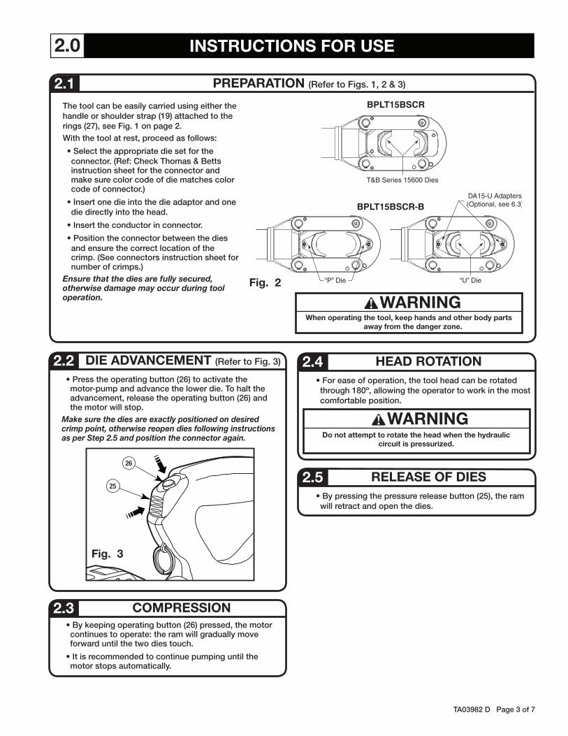
“P” Die
BPLT15BSCR-B
BPLT15BSCR
“U” Die
DA15-U Adapters(Optional, see 6.3)
T&B Series 15600 Dies
TA03982 D Page 3 of 7
2.0 INSTRUCTIONS FOR USE
The tool can be easily carried using either the handle or shoulder strap (19) attached to the rings (27), see Fig 1 on page 2 With the tool at rest, proceed as follows:
• Select the appropriate die set for the connector (Ref: Check Thomas & Betts instruction sheet for the connector and make sure color code of die matches color code of connector )
• Insert one die into the die adaptor and one die directly into the head
• Insert the conductor in connector
• Position the connector between the dies and ensure the correct location of the crimp (See connectors instruction sheet for number of crimps )
Ensure that the dies are fully secured, otherwise damage may occur during tool operation.
PREPARATION (Refer to Figs 1, 2 & 3) 2.1
• Press the operating button (26) to activate the motor-pump and advance the lower die To halt the advancement, release the operating button (26) and the motor will stop
Make sure the dies are exactly positioned on desired crimp point, otherwise reopen dies following instructions as per Step 2.5 and position the connector again.
DIE ADVANCEMENT (Refer to Fig 3) 2.2
Fig. 2
COMPRESSION 2.3 • By keeping operating button (26) pressed, the motor continues to operate: the ram will gradually move forward until the two dies touch
• It is recommended to continue pumping until the motor stops automatically
• For ease of operation, the tool head can be rotated through 180º, allowing the operator to work in the most comfortable position
HEAD ROTATION 2.4
WARNINGDo not attempt to rotate the head when the hydraulic
circuit is pressurized.
• By pressing the pressure release button (25), the ram will retract and open the dies
RELEASE OF DIES2.5
Fig. 3
WARNINGWhen operating the tool, keep hands and other body parts
away from the danger zone.

STORAGE (Refer to Fig 6)4.3 When not in use, the tool should be stored and transported in the metal case, to prevent damage This case is suitable for storing the tool, and its accessories
Metal Case: size 22 3x16x5 1 inches, (566x406x130 mm) weighs 14 8 lbs (6,7 kg)
Fig. 6
29
TA03982 D Page 4 of 7
3.0 BATTERY USEThe tool is supplied with the batteries completely discharged; before use, fully charge the batteries using the charger supplied.
USING THE BATTERY CHARGER3.2 Carefully follow the instructions in the battery charger manual
In order to use the batteries correctly, please follow these rules:
• Use the battery until the automatic residual energy display still has 1-2 LEDs showing: this means the battery is almost completely discharged and no loss in the life of the battery has been produced
• Be particularly careful when charging a new battery the first 2-3 times in order to maximize the available energy level
• Allow the battery to cool down to ambient temperature prior to recharging
• Rest the battery charger for at least 15 minutes between charges
4.0 MAINTENANCE
The tool is robust, completely sealed, and requires very little daily maintenance. Compliance with the following points, should help to maintain the optimum performance of the tool:
THOROUGH CLEANING4.1 Dust, sand and dirt are a danger for any hydraulic device Every day, after use, the tool must be wiped with a clean cloth taking care to remove any residue, especially close to pivots and moveable parts
OIL FILL4.2 Top off the oil, if necessary, as follows:- Remove the battery - Place the tool in a vertical
position and remove the filler cap (29) located inside the battery housing, taking care not to splash any oil onto the housing
- Fill the reservoir to the top - Replace the filler cap (29)
Fig. 5
34
BATTERY STATUS (Refer to Fig 4) 3.1
Fig. 4
• After releasing the operating button, the residual battery capacity is automatically displayed for 5 seconds on the indicator (34) The number of LEDs illuminated indicates the residual capacity:
8 LEDs illuminated: Fully Charged4 LEDs illuminated: 50% capacity1 LED illuminated: Minimum charge
When replacing the battery, press the two points marked with the word “PUSH” at the same time, remove the flat battery from its housing and insert the new one
USING THE BATTERY3.3
P-P
N
N
P
P
R R
N-N
R-R
Q-Q
35
36
26
1213 070809101114
29
32
27
28
30
31
33
24
25
34
23
01
02
03
06
2221201918171615
04 05
38
37
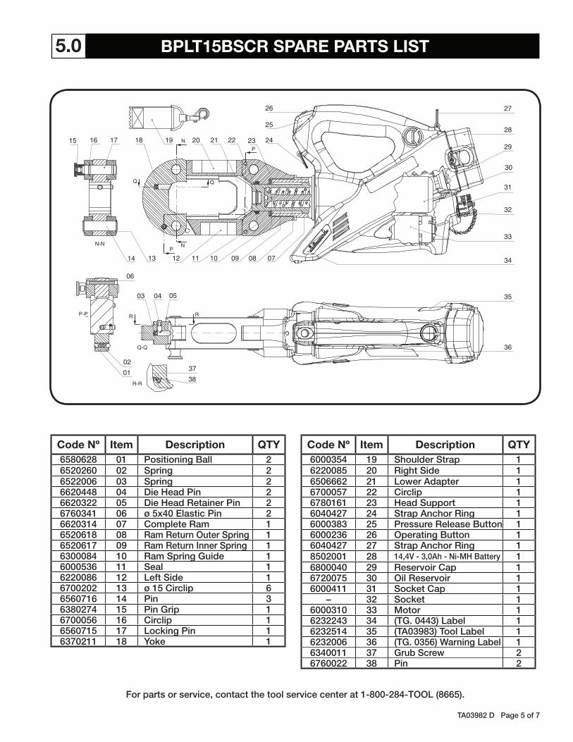
5.0 BPLT15BSCR SPARE PARTS LIST
TA03982 D Page 5 of 7
Code Nº Item Description QTY6580628 01 Positioning Ball 26520260 02 Spring 26522006 03 Spring 26620448 04 Die Head Pin 26620322 05 Die Head Retainer Pin 26760341 06 ø 5x40 Elastic Pin 26620314 07 Complete Ram 16520618 08 Ram Return Outer Spring 16520617 09 Ram Return Inner Spring 16300084 10 Ram Spring Guide 16000536 11 Seal 16220086 12 Left Side 16700202 13 ø 15 Circlip 66560716 14 Pin 36380274 15 Pin Grip 16700056 16 Circlip 16560715 17 Locking Pin 16370211 18 Yoke 1
Code Nº Item Description QTY6000354 19 Shoulder Strap 16220085 20 Right Side 16506662 21 Lower Adapter 16700057 22 Circlip 16780161 23 Head Support 16040427 24 Strap Anchor Ring 16000383 25 Pressure Release Button 16000236 26 Operating Button 16040427 27 Strap Anchor Ring 18502001 28 14,4V - 3,0Ah - Ni-MH Battery 16800040 29 Reservoir Cap 16720075 30 Oil Reservoir 16000411 31 Socket Cap 1
– 32 Socket 16000310 33 Motor 16232243 34 (TG. 0443) Label 16232514 35 (TA03983) Tool Label 16232006 36 (TG. 0356) Warning Label 16340011 37 Grub Screw 26760022 38 Pin 2
For parts or service, contact the tool service center at 1-800-284-TOOL (8665).
N
NP
P
N-N
35
36
26
12 7031 0809101114
P-P
29
32
27
28
30
31
33
24
25
34
23
01
02
03
04
06
05
2221201918171615
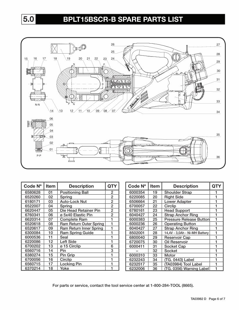
5.0 BPLT15BSCR-B SPARE PARTS LIST
TA03982 D Page 6 of 7
Code Nº Item Description QTY6580628 01 Positioning Ball 26520260 02 Spring 26180171 03 Auto-Lock Nut 26522007 04 Spring 26620447 05 Die Head Retainer Pin 26760341 06 ø 5x40 Elastic Pin 26620314 07 Complete Ram 16520618 08 Ram Return Outer Spring 16520617 09 Ram Return Inner Spring 16300084 10 Ram Spring Guide 16000536 11 Seal 16220086 12 Left Side 16700202 13 ø 15 Circlip 66560716 14 Pin 36380274 15 Pin Grip 16700056 16 Circlip 16560715 17 Locking Pin 16370214 18 Yoke 1
Code Nº Item Description QTY6000354 19 Shoulder Strap 16220085 20 Right Side 16506664 21 Lower Adapter 16700057 22 Circlip 16780161 23 Head Support 16040427 24 Strap Anchor Ring 16000383 25 Pressure Release Button 16000236 26 Operating Button 16040427 27 Strap Anchor Ring 18502001 28 14,4V - 3,0Ah - Ni-MH Battery 16800040 29 Reservoir Cap 16720075 30 Oil Reservoir 16000411 31 Socket Cap 1
– 32 Socket 16000310 33 Motor 16232243 34 (TG. 0443) Label 16232517 35 (TA03984) Tool Label 16232006 36 (TG. 0356) Warning Label 1
For parts or service, contact the tool service center at 1-800-284-TOOL (8665).

“U” DIE ADAPTER6.3 DA15-UAdapter for accepting “U” Dies
93
31
32
92
28
TA03982 D Page 7 of 7© 2012 Thomas & Betts All Rights Reserved
Thomas & Betts CorporationMemphis, Tennessee
www tnb com
WARRANTY: Thomas & Betts sells this product with the understanding that the user will perform all necessary tests to determine the suitability of this product for the user’s intended application Thomas & Betts warrants that this product will be free from defects in materials and workmanship for the period stated on the enclosed warranty card Upon prompt notification of any warranted defect, Thomas & Betts will, at its option, repair or replace the defective product or refund the purchase price Proof of purchase is required Misuse or unauthorized modification of the product voids all warranties
Limitations and Exclusions: THE ABOVE WARRANTY IS THE SOLE WARRANTY CONCERNING THIS PRODUCT, AND IS IN LIEU OF ALL OTHER WARRANTIES EXPRESS OR IMPLIED, INCLUDING BUT NOT LIMITED TO ANY IMPLIED WARRANTY OF MERCHANTABILITY OR FITNESS FOR A PARTICULAR PURPOSE, WHICH ARE SPECIFICALLY DISCLAIMED. LIABILITY FOR BREACH OF THE ABOVE WARRANTY IS LIMITED TO COST OF REPAIR OR REPLACEMENT OF THE PRODUCT, AND UNDER NO CIRCUMSTANCES WILL THOMAS & BETTS BE LIABLE FOR ANY INDIRECT, SPECIAL, INCIDENTAL OR CONSEQUENTIAL DAMAGES.
For parts or service, contact the tool service center at 1-800-284-TOOL (8665)
6.0 OPTIONAL ACCESSORIES
POWER SUPPLY6.1 BPS110-14Y cod. 2598501Network Power Supply(input: 110V 50-60 Hz)(output: 14 4 V DC)
CONNECTING CABLE6.2 ESC 600 cod. 2599001Connecting Cable with Spring Clips(For power from an external source, length 20 ft)
POWER FROM EXTERNAL SOURCE6.4 Using the integral socket (32) the tool can be powered from an external power supply (min. 30A) or vehicle battery Using the special connection cable type ESC 600, available as an optional accessory,proceed as follows:
- Make sure the supply voltage is between 12 and 14,4 V DC.- Connect the spring clips to the external supply ensuring correct polarity, red to positive pole (+), black to negative pole (–) - Remove cap (31) from the socket (32) on the tool and insert connector (93), tightening the bezel clockwise until it locks
The tool is powered for operation Proceed as described in 2 0 - When the work is completed, disconnect the cable (92) and replace the protective cap (31)
If the poles are accidentally reversed, the tool will not be damaged but will operate using only the integral battery (28); reverse the polarity of the spring clips to use the external power source
WARNINGWHEN USING AN EXTERNAL POWER SUPPLY, NEVER SHORT CIRCUIT THE METAL CONTACTS INSIDE THE BATTERY HOUSING. WE ADVISE LEAVING THE BATTERY (28) IN ITS HOUSING AS IT WILL SUPPLY POWER IN PARALLEL WITH THE EXTERNAL SOURCE.