bpi42cr and bpi42300cr battery operated ... - tnb.com
TRANSCRIPT
IMPORTANT: Read and understand all of the instructions and safety information in this manual before operating or servicing this tool.
BPI42CR and BPI42300CRBattery Operated Hydraulic Crimping Tool
Operating Instruction Manual
1.0 General Characteristics 22.0 Instructions for Use 33.0 Battery and Charger Use 4-54.0 Maintenance 55.0 Spare Parts List 6 5 1 Table 1 7 5 2 Table 2 8
Table of Contents
TA04492 B Page 1 of 8
5 6 71 2 4 4Ni-MH
3
3
8
11
600
24
27
2
13
See 3.1(Fig. 4)
1.0 GENERAL CHARACTERISTICS
BATTERY OPERATED HYDRAULIC CRIMPING TOOL
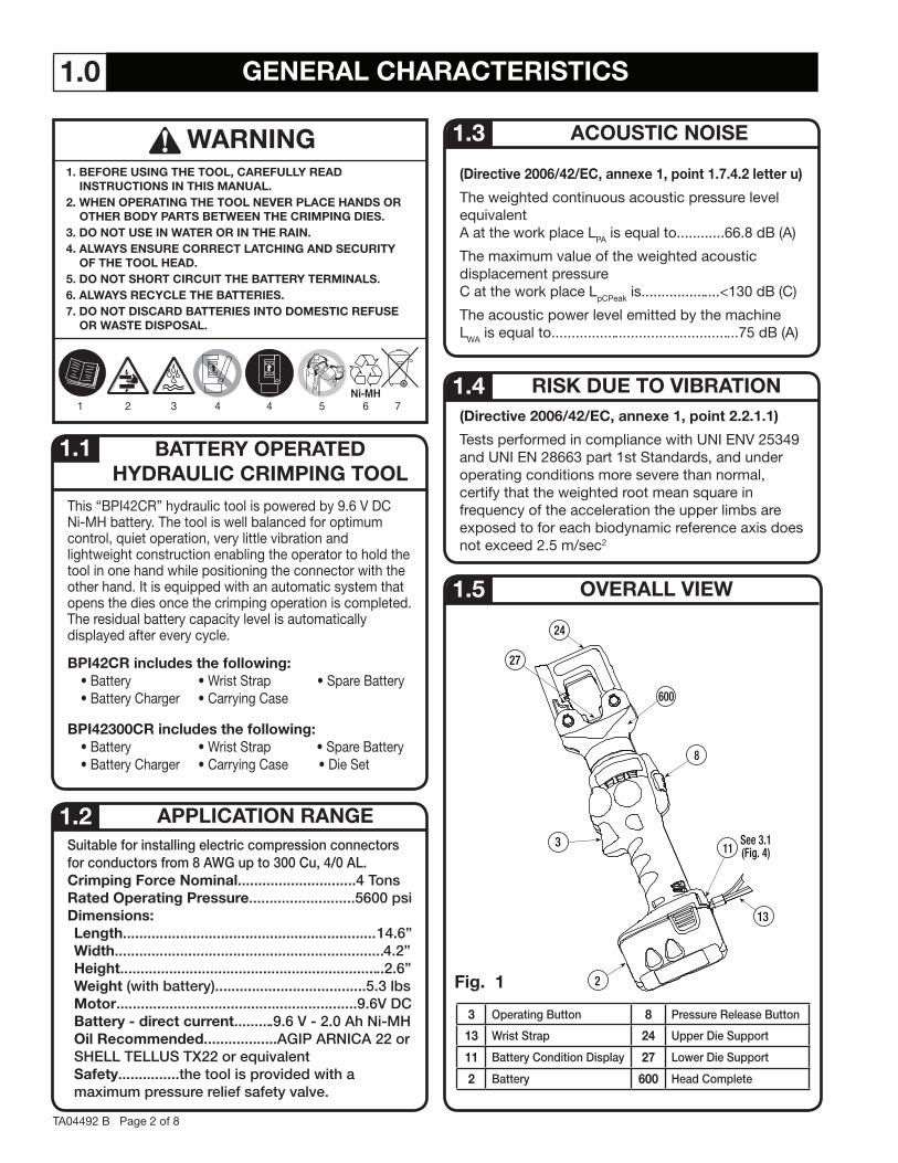
This “BPI42CR” hydraulic tool is powered by 9.6 V DC Ni-MH battery. The tool is well balanced for optimum control, quiet operation, very little vibration and lightweight construction enabling the operator to hold the tool in one hand while positioning the connector with the other hand. It is equipped with an automatic system that opens the dies once the crimping operation is completed. The residual battery capacity level is automatically displayed after every cycle.
BPI42CR includes the following:• Battery • Wrist Strap • Spare Battery• Battery Charger • Carrying Case
BPI42300CR includes the following:• Battery • Wrist Strap • Spare Battery• Battery Charger • Carrying Case • Die Set
Suitable for installing electric compression connectors for conductors from 8 AWG up to 300 Cu, 4/0 AL Crimping Force Nominal 4 TonsRated Operating Pressure 5600 psiDimensions:Length 14 6”Width 4 2”Height 2 6”Weight (with battery) 5 3 lbsMotor 9 6V DCBattery - direct current 9 6 V - 2 0 Ah Ni-MHOil Recommended AGIP ARNICA 22 or SHELL TELLUS TX22 or equivalentSafety the tool is provided with a maximum pressure relief safety valve
(Directive 2006/42/EC, annexe 1, point 1.7.4.2 letter u)
The weighted continuous acoustic pressure level equivalentA at the work place LPA is equal to............66.8 dB (A)
The maximum value of the weighted acoustic displacement pressureC at the work place LpCPeak is....................<130 dB (C)
The acoustic power level emitted by the machineLWA is equal to...............................................75 dB (A)
(Directive 2006/42/EC, annexe 1, point 2.2.1.1)
Tests performed in compliance with UNI ENV 25349 and UNI EN 28663 part 1st Standards, and under operating conditions more severe than normal, certify that the weighted root mean square in frequency of the acceleration the upper limbs are exposed to for each biodynamic reference axis does not exceed 2.5 m/sec2
1.5 OVERALL VIEW
1.1
APPLICATION RANGE1.2
3 Operating Button 8 Pressure Release Button
13 Wrist Strap 24 Upper Die Support
11 Battery Condition Display 27 Lower Die Support
2 Battery 600 Head Complete
RISK DUE TO VIBRATION
ACOUSTIC NOISE1.3
1.4
Fig. 1
TA04492 B Page 2 of 8
WARNING1. BEFORE USING THE TOOL, CAREFULLY READ
INSTRUCTIONS IN THIS MANUAL.2. WHEN OPERATING THE TOOL NEVER PLACE HANDS OR
OTHER BODY PARTS BETWEEN THE CRIMPING DIES.3. DO NOT USE IN WATER OR IN THE RAIN.4. ALWAYS ENSURE CORRECT LATCHING AND SECURITY
OF THE TOOL HEAD.5. DO NOT SHORT CIRCUIT THE BATTERY TERMINALS.6. ALWAYS RECYCLE THE BATTERIES.7. DO NOT DISCARD BATTERIES INTO DOMESTIC REFUSE
OR WASTE DISPOSAL.
24
27
25
3
8
TA04492 B Page 3 of 8
2.0 INSTRUCTIONS FOR USE
The tool is supplied with the batteries completely discharged; before use, fully charge the batteries using the charger supplied. See section 3.0 The tool can be easily carried using either the handle or wrist strap, see Fig. 1.With the tool at rest, proceed as follows:
• Select the appropriate die set for the connector. (Ref: Check Thomas & Betts instruction sheet for the connector and make sure color code of die matches color code of connector.)
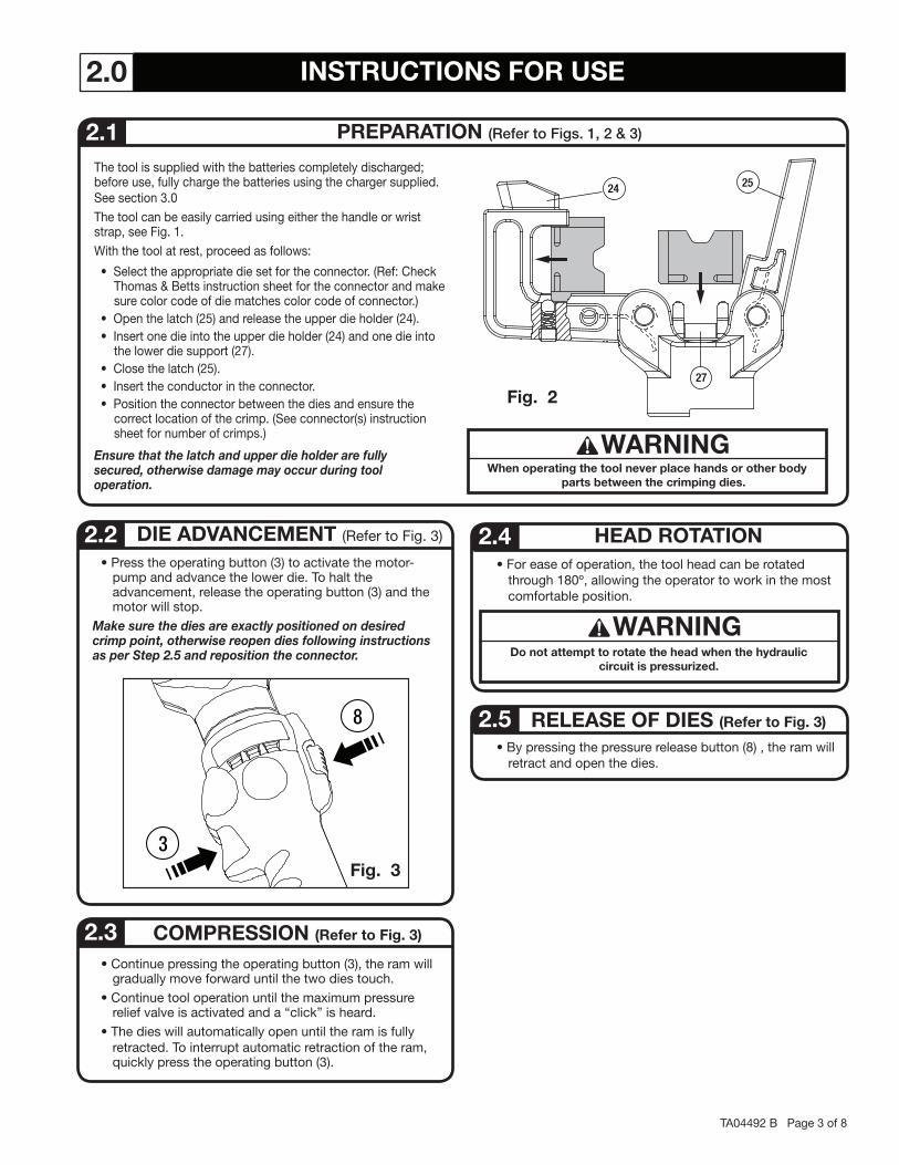
• Open the latch (25) and release the upper die holder (24).• Insert one die into the upper die holder (24) and one die into
the lower die support (27).• Close the latch (25).• Insert the conductor in the connector.• Position the connector between the dies and ensure the
correct location of the crimp. (See connector(s) instruction sheet for number of crimps.)
Ensure that the latch and upper die holder are fully secured, otherwise damage may occur during tool operation.
PREPARATION (Refer to Figs 1, 2 & 3) 2.1
• Press the operating button (3) to activate the motor-pump and advance the lower die. To halt the advancement, release the operating button (3) and the motor will stop.
Make sure the dies are exactly positioned on desired crimp point, otherwise reopen dies following instructions as per Step 2.5 and reposition the connector.
DIE ADVANCEMENT (Refer to Fig. 3) 2.2
Fig. 2
COMPRESSION (Refer to Fig. 3) 2.3 • Continue pressing the operating button (3), the ram will
gradually move forward until the two dies touch.• Continue tool operation until the maximum pressure
relief valve is activated and a “click” is heard.• The dies will automatically open until the ram is fully
retracted. To interrupt automatic retraction of the ram, quickly press the operating button (3).
• For ease of operation, the tool head can be rotated through 180º, allowing the operator to work in the most comfortable position.
HEAD ROTATION 2.4
WARNINGDo not attempt to rotate the head when the hydraulic
circuit is pressurized.
• By pressing the pressure release button (8) , the ram will retract and open the dies.
RELEASE OF DIES (Refer to Fig. 3)2.5
Fig. 3
WARNINGWhen operating the tool never place hands or other body
parts between the crimping dies.
11
LEDs
Fig. 4
TA04492 B Page 4 of 8
3.0 BATTERY AND CHARGER USEThe tool is supplied with the batteries completely discharged; before use, fully charge the batteries using the charger supplied.
This tool is supplied with a battery charger CFC 120Y and adapter CBA96-144, which is required for 9.6V batteries (CB9620H). With the adapter removed, the same charger may be used with the 14.4 V Batteries common to other Thomas & Betts battery operated tools.
For optimum battery life, please follow the rules:
• Use the battery until the automatic residual energy display still has 1-2 red LEDs showing: this means the battery is almost completely discharged and no loss in the life of the battery has been produced. This is particularly important when charging a new battery the first 2-3 times in order to maximize the available energy level.
• Allow the battery to cool down to ambient temperature prior to recharging.
• Rest the battery charger for at least 15 minutes between charges.
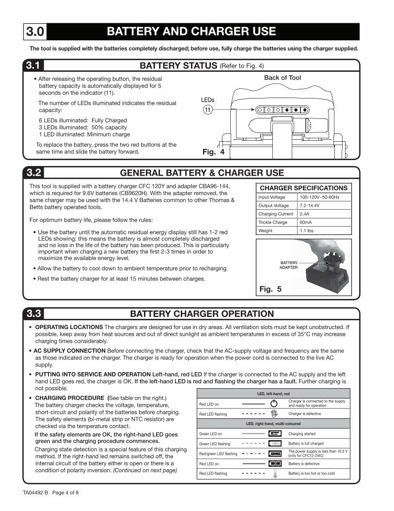
BATTERY STATUS (Refer to Fig. 4) 3.1 • After releasing the operating button, the residual
battery capacity is automatically displayed for 5 seconds on the indicator (11).
The number of LEDs illuminated indicates the residual capacity:
6 LEDs illuminated: Fully Charged3 LEDs illuminated: 50% capacity1 LED illuminated: Minimum charge
To replace the battery, press the two red buttons at the same time and slide the battery forward.
GENERAL BATTERY & CHARGER USE3.2 CHARGER SPECIFICATIONS
Input Voltage 100-120V~50-60Hz
Output Voltage 7.2-14.4V
Charging Current 2.4A
Trickle Charge 60mA
Weight 1.1 lbs.
Fig. 5
Back of Tool
• OPERATING LOCATIONS The chargers are designed for use in dry areas. All ventilation slots must be kept unobstructed. If possible, keep away from heat sources and out of direct sunlight as ambient temperatures in excess of 35°C may increase charging times considerably.
• AC SUPPLY CONNECTION Before connecting the charger, check that the AC-supply voltage and frequency are the same as those indicated on the charger. The charger is ready for operation when the power cord is connected to the live AC supply.
• PUTTING INTO SERVICE AND OPERATION Left-hand, red LED If the charger is connected to the AC supply and the left hand LED goes red, the charger is OK. If the left-hand LED is red and flashing the charger has a fault Further charging is not possible.
• CHARGING PROCEDURE (See table on the right.) The battery charger checks the voltage, temperature,
short-circuit and polarity of the batteries before charging. The safety elements (bi-metal strip or NTC resistor) are checked via the temperature contact.
If the safety elements are OK, the right-hand LED goes green and the charging procedure commences
Charging state detection is a special feature of this charging method. If the right-hand led remains switched off, the internal circuit of the battery either is open or there is a condition of polarity inversion. (Continued on next page)
BATTERY CHARGER OPERATION3.3
LED, left-hand, red
LED, right-hand, multi-coloured
Red LED on
Red LED �ashing
Red LED on
Red/green LED �ashing
Green LED �ashing
Green LED on
Red LED �ashing
Charger is connected to the supplyand ready for operation
Charger is defective
Charging started
Battery is full charged
The power supply is less than 10,5 V(only for CFC12-24IC)
Battery is defective
Battery is too hot or too cold
100%
BATTERYADAPTER
TA04492 B Page 5 of 8
4.0 MAINTENANCE
The tool is completely sealed, and requires very little daily maintenance. Compliance with the following recommendations, should help to maintain the optimum performance of the tool:
THOROUGH CLEANING4.1 Dust, sand and dirt are a danger for any hydraulic device After every use, the tool must be wiped with a clean cloth taking care to remove any residue, especially close to moveable parts
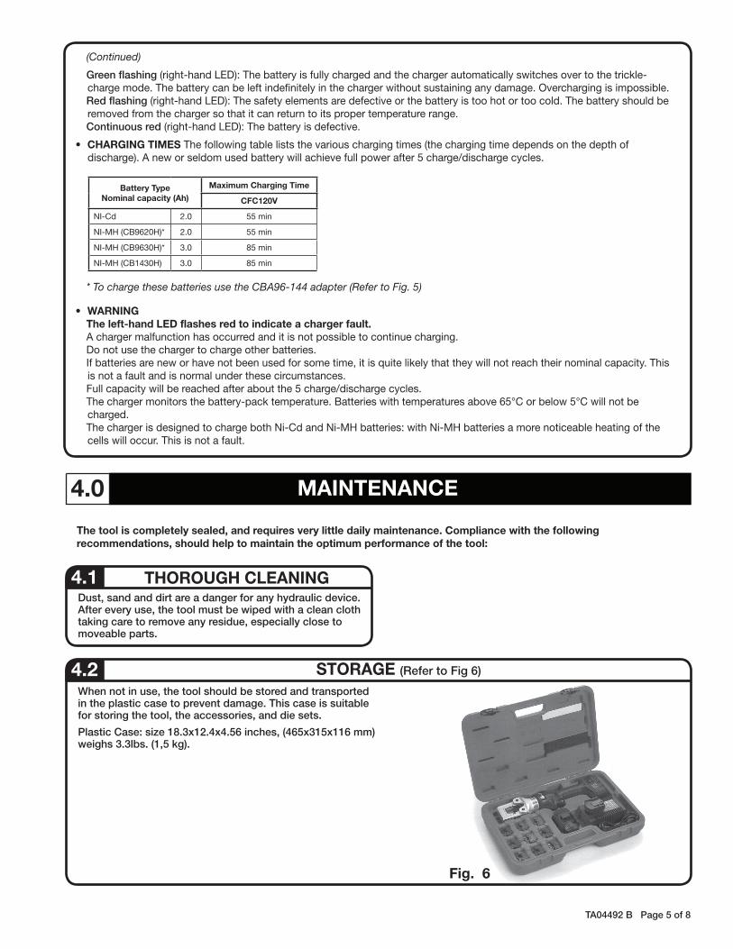
STORAGE (Refer to Fig 6)4.2 When not in use, the tool should be stored and transported in the plastic case to prevent damage This case is suitable for storing the tool, the accessories, and die sets
Plastic Case: size 18 3x12 4x4 56 inches, (465x315x116 mm) weighs 3 3lbs (1,5 kg)
Fig. 6
(Continued)
Green flashing (right-hand LED): The battery is fully charged and the charger automatically switches over to the trickle-charge mode. The battery can be left indefinitely in the charger without sustaining any damage. Overcharging is impossible.
Red flashing (right-hand LED): The safety elements are defective or the battery is too hot or too cold. The battery should be removed from the charger so that it can return to its proper temperature range.
Continuous red (right-hand LED): The battery is defective.
• CHARGING TIMES The following table lists the various charging times (the charging time depends on the depth of discharge). A new or seldom used battery will achieve full power after 5 charge/discharge cycles.
* To charge these batteries use the CBA96-144 adapter (Refer to Fig. 5)
• WARNING The left-hand LED flashes red to indicate a charger fault. A charger malfunction has occurred and it is not possible to continue charging. Do not use the charger to charge other batteries. If batteries are new or have not been used for some time, it is quite likely that they will not reach their nominal capacity. This
is not a fault and is normal under these circumstances. Full capacity will be reached after about the 5 charge/discharge cycles. The charger monitors the battery-pack temperature. Batteries with temperatures above 65°C or below 5°C will not be
charged. The charger is designed to charge both Ni-Cd and Ni-MH batteries: with Ni-MH batteries a more noticeable heating of the
cells will occur. This is not a fault.
Battery TypeNominal capacity (Ah)
Maximum Charging Time
CFC120V
NI-Cd 2.0 55 min
NI-MH (CB9620H)* 2.0 55 min
NI-MH (CB9630H)* 3.0 85 min
NI-MH (CB1430H) 3.0 85 min
TA04492 B Page 6 of 8
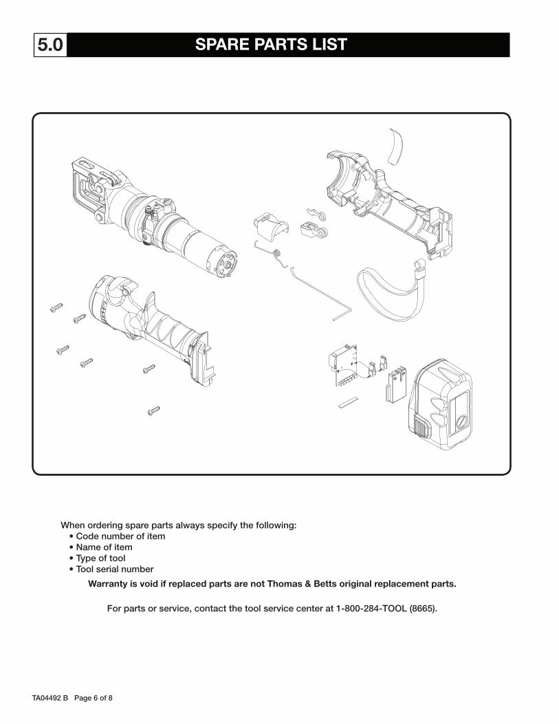
5.0 SPARE PARTS LIST
When ordering spare parts always specify the following:• Code number of item• Name of item• Type of tool• Tool serial number
Warranty is void if replaced parts are not Thomas & Betts original replacement parts.
For parts or service, contact the tool service center at 1-800-284-TOOL (8665)
TA04492 B Page 7 of 8
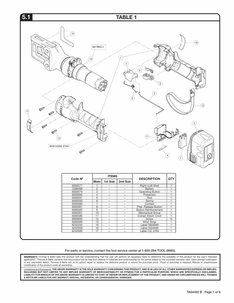
TABLE 15.1
Code NºITEMS
DESCRIPTION QTYMain 1st Sub 2nd Sub
6000577 1 – – Right+Left Shell 12598498 2 – – Battery 16000579 3 – – Operating Button 16000584 4 – – Protection 16000591 5 – – Rod 16000593 6 – – Spring 16000580 7 – – Contact 16000581 8 – – Pres. Release Button 16000582 9 – – Button Reinforcement 16000301 10 – – Mechanical Group 16000586 11 – – Compl. Electr. Circit 16900650 12 – – Screw 66000589 13 – – Wrist Strap 16232220 15 – – Label TA03948 16232558 16 – – Label TA04490 16232500 17 – – Label T.G. 0704 1
5
13
16
9
8
6
3
2
74
11
1
12
17
15
10
See TABLE 2
xxxxxx
Serial number of tool
WARRANTY: Thomas & Betts sells this product with the understanding that the user will perform all necessary tests to determine the suitability of this product for the user’s intended application. Thomas & Betts warrants that this product will be free from defects in materials and workmanship for the period stated on the enclosed warranty card. Upon prompt notification of any warranted defect, Thomas & Betts will, at its option, repair or replace the defective product or refund the purchase price. Proof of purchase is required. Misuse or unauthorized modification of the product voids all warranties.
Limitations and Exclusions: THE ABOVE WARRANTY IS THE SOLE WARRANTY CONCERNING THIS PRODUCT, AND IS IN LIEU OF ALL OTHER WARRANTIES EXPRESS OR IMPLIED, INCLUDING BUT NOT LIMITED TO ANY IMPLIED WARRANTY OF MERCHANTABILITY OR FITNESS FOR A PARTICULAR PURPOSE, WHICH ARE SPECIFICALLY DISCLAIMED. LIABILITY FOR BREACH OF THE ABOVE WARRANTY IS LIMITED TO COST OF REPAIR OR REPLACEMENT OF THE PRODUCT, AND UNDER NO CIRCUMSTANCES WILL THOMAS & BETTS BE LIABLE FOR ANY INDIRECT, SPECIAL, INCIDENTAL OR CONSEQUENTIAL DAMAGES.
For parts or service, contact the tool service center at 1-800-284-TOOL (8665)
TA04492 B Page 8 of 8© 2010 Thomas & Betts. All Rights Reserved.
Thomas & Betts CorporationMemphis, Tennessee
www.tnb.com
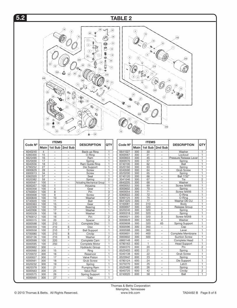
TABLE 25.2
Code NºITEMS
DESCRIPTION QTYMain 1st Sub 2nd Sub
6040240 4 – – Back-up Ring 16360300 15 – – O-Ring 16620490 16 – – Ram 16520030 17 – – Spring 16040556 18 – – Ram Guide Ring 16780252 27 – – Die Support 16900629 28 – – Screw 16900013 34 – – Screw 16362020 57 – – Seal 16520382 59 – – Spring 26000597 100 – – Actuating Mechanical Group 16000357 100 1 – Housing 16000358 100 4 – Gear 16760004 100 8 – Pin 36900008 100 9 – Screw 26000849 100 10 – Washer 26740020 100 11 – Ball 26000363 100 15 – Gear 36402009 100 16 – Bearing 16402006 100 17 – Washer 16000328 100 18 – Washer 16760012 100 19 – Pin 26000315 100 20 – Spacer 36000598 100 210 – Complete Disc 16000359 100 210 6 Disc 16000558 100 210 7 Ball Support 16700080 100 210 8 Circlip 16650136 100 210 9 Washer 26000599 100 220 – Complete Cam 16000595 100 250 – Complete Motor 16000662 300 – – Hydraulic Group 16000560 300 15 – Ring 16720072 300 16 – Reservoir 16300027 300 17 – Valve Piston 16000561 300 18 – Grub Screw 16520232 300 19 – Spring 16620378 300 21 – Pumping Ram 16000563 300 24 – Valve Rod 16000575 300 26 – Spring Support 16000565 300 27 – Cap 1
Code NºITEMS
DESCRIPTION QTYMain 1st Sub 2nd Sub
6641027 300 30 – Washer 16000567 300 31 – Lockout 16000603 300 45 – Pressure Release Lever 16000570 300 57 – Spring 16740100 300 62 – Ball 16520160 300 63 – Spring 16340590 300 64 – Grub Screw 16520200 300 65 – Spring 16740120 300 66 – Ball 7/32” 13041046 300 67 – Tie 26640205 300 68 – Washer 16900052 300 69 – Screw M4X6 16000602 300 70 – Spring 16900054 300 71 – Screw M4X6 16360022 300 72 – O-Ring 16360125 300 75 – O-Ring 16641020 300 77 – Washer D6 CU 16160081 300 310 – Body 16000697 300 320 – Release Group 16520240 300 320 1 Spring 16000318 300 320 2 Spring 16900021 300 320 3 Screw M3X8 16000849 300 320 4 Washer 16000608 300 320 65 Spring Support 16000596 300 350 – Cap 16000588 300 360 – Lever 16000601 300 400 – Complete Membrane 16900602 300 500 – Suction Screw 16860148 600 – – Complete Head 16780163 600 1 – Head Support 16560370 600 20 – Pin 26520403 600 21 – Spring 16340138 600 22 – Grub Screw 16520942 600 23 – Spring 16780124 600 24 – Die Support 16370270 600 25 – Latch 16520482 600 26 – Spring 16040725 600 42 – Circlip 26740020 600 58 – Ball 1
57
4
19
18
1
250
10
98
210
20
16
17
1511
8
96
7
21
57
300
15
100
11
220
500
18
17
400
5823
24
26
31
165
27
19
18
7217
75
30
6716
35067
64
6566
310
70
45
63
77360
71
62
4
15
34
6916
2142
26
600
68
3
4
2
320
22 1
27
2859
24
25
20