bpi 1200 standard practice for basic analysis of...
TRANSCRIPT

1
BPI‐1200 Standard Practice for Basic Analysis of Buildings
Comparison between ANSI/BPI‐1200 (5‐18‐15) and BPI‐1200 (9‐26‐13)
Section 9/26/13 Version 5/18/15 Version Explanation/Notes
Introduction Added: It is understood that other standards or guidelines may be required by the Authority Having Jurisdiction (AHJ) and in such instances the energy auditor should comply with the AHJ’s requirements.
This makes it clear that an auditor can still be considered in compliance with this standard if he/she has to perform certain portions of it differently than indicated due to Program or Local Code requirements.
Section 1 ‐ Scope No significant difference, same language, just rearranged
Section 2 ‐ General Requirements
Provided a general overarching statement and requirement for a homeowner interview
Standard now referencesSection 2 of BPI‐1100
By pointing to BPI‐1100, the 5/18/15 version provides more specific guidance.
Section 3‐ Health and Safety
Standard now referencesSection 3 of BPI‐1100
Does not significantly impact requirements
Section 4 ‐ Disclosure and Ethics
Standard now references Section 4 of BPI‐1100
Does not significantly impact requirements
Section 5 ‐ Cost Benefit Analysis
Standard now references Section 5 of BPI‐1100, but also provides additional detail
The only significant changes are: a. The RESNET reference has been
updated b. “Generally accepted engineering
estimates” are now allowed (previously implied but not implicitly stated
c. Auditor is now required to make every effort to obtain previous energy use records
Section 6 ‐ Prioritizing Recommendations
NO CHANGE
Section 8 Indoor Air Quality and Ventilation
Standard now references Section 8 of BPI‐1100. 8.3.5 For ducts located outside the pressure boundary, recommend R‐8 insulation at a minimum.
The majority of content in this section is now in an informative annex. (Annex I). Also, the highlighted section to the left is a new requirement.
2
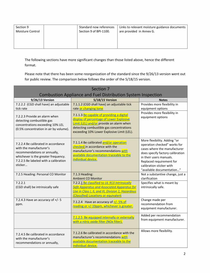
Section 9 Moisture Control
Standard now references Section 9 of BPI‐1100.
Links to relevant moisture guidance documents are provided in Annex G.
The following sections have more significant changes than those listed above, hence the different
format.
Please note that there has been some reorganization of the standard since the 9/26/13 version went out
for public review. The comparison below follows the order of the 5/18/15 version.
Section 7Combustion Appliance and Fuel Distribution System Inspection
9/26/13 Version 5/18/15 Version Notes
7.2.2.2 (CGD shall have) an adjustable tick rate
7.1.1.2 (CGD shall have) an adjustable tick rate or changing tone
Provides more flexibility in equipment options
7.2.2.3 Provide an alarm when detecting combustible gas concentrations exceeding 10% LEL (0.5% concentration in air by volume).
7.1.1.3 Be capable of providing a digital display of percentage of Lower Explosive Limit (LEL) and/or provide an alarm when detecting combustible gas concentrations exceeding 10% Lower Explosive Limit (LEL).
Provides more flexibility in equipment options
7.2.2.4 Be calibrated in accordance with the manufacturer’s recommendations or annually, whichever is the greater frequency. 7.2.2.5 Be labeled with a calibration sticker…
7.1.1.4 Be calibrated and/or operation checked in accordance with the manufacturer’s recommendations with available documentation traceable to the individual device.
More flexibility. Adding “or operation checked” works for cases where the manufacturer does specify factory calibration in their users manuals. Replaced requirement for calibration sticker with “available documentation…”
7.2.5 Heading: Personal CO Monitor 7.1.3 Heading:Ambient CO Monitor
Not a substantive change, just a clarification
7.2.2.1 (CGD shall) be intrinsically safe
7.2.2.1 Be classified to UL 913 Intrinsically Safe Apparatus and Associated Apparatus for Use in Class I, II, and III, Division 1, Hazardous (Classified) Locations or equivalent
Specifies what is meant by intrinsically safe.
7.2.4.3 Have an accuracy of +/‐ 5 ppm.
7.1.2.4 Have an accuracy of +/‐ 5% of reading or +/‐10ppm, whichever is greater.
Change made per recommendation from equipment manufacturer.
7.1.2.5 Be equipped internally or externally with a nitric oxide filter (NOx filter).
Added per recommendation from equipment manufacturer.
7.2.4.5 Be calibrated in accordance with the manufacturer’s recommendations or annually,
7.1.2.6 Be calibrated in accordance with the manufacturer’s recommendations with available documentation traceable to the individual device.
Allows more flexibility.
3
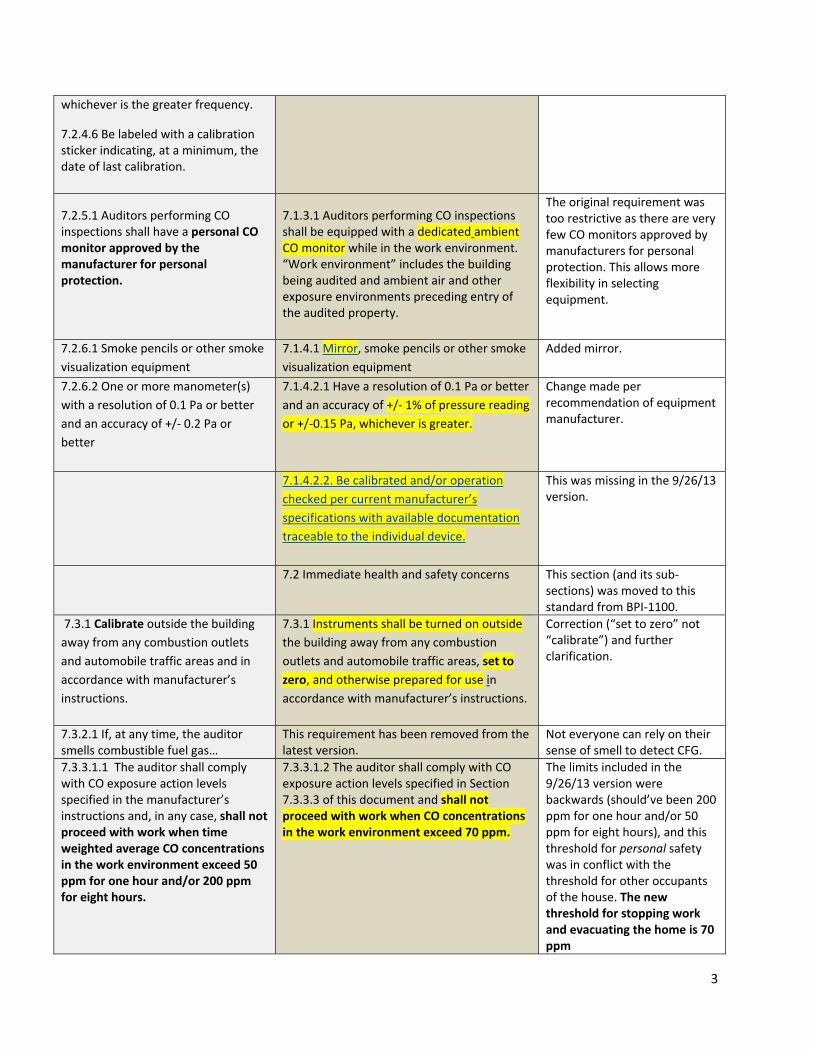
whichever is the greater frequency.
7.2.4.6 Be labeled with a calibration sticker indicating, at a minimum, the date of last calibration.
7.2.5.1 Auditors performing CO inspections shall have a personal CO monitor approved by the manufacturer for personal protection.
7.1.3.1 Auditors performing CO inspections shall be equipped with a dedicated ambient CO monitor while in the work environment. “Work environment” includes the building being audited and ambient air and other exposure environments preceding entry of the audited property.
The original requirement was too restrictive as there are very few CO monitors approved by manufacturers for personal protection. This allows more flexibility in selecting equipment.
7.2.6.1 Smoke pencils or other smoke
visualization equipment
7.1.4.1 Mirror, smoke pencils or other smoke
visualization equipment
Added mirror.
7.2.6.2 One or more manometer(s)
with a resolution of 0.1 Pa or better
and an accuracy of +/‐ 0.2 Pa or
better
7.1.4.2.1 Have a resolution of 0.1 Pa or better
and an accuracy of +/‐ 1% of pressure reading
or +/‐0.15 Pa, whichever is greater.
Change made per recommendation of equipment manufacturer.
7.1.4.2.2. Be calibrated and/or operation
checked per current manufacturer’s
specifications with available documentation
traceable to the individual device.
This was missing in the 9/26/13 version.
7.2 Immediate health and safety concerns This section (and its sub‐sections) was moved to this standard from BPI‐1100.
7.3.1 Calibrate outside the building
away from any combustion outlets
and automobile traffic areas and in
accordance with manufacturer’s
instructions.
7.3.1 Instruments shall be turned on outside
the building away from any combustion
outlets and automobile traffic areas, set to
zero, and otherwise prepared for use in
accordance with manufacturer’s instructions.
Correction (“set to zero” not “calibrate”) and further clarification.
7.3.2.1 If, at any time, the auditor smells combustible fuel gas…
This requirement has been removed from the latest version.
Not everyone can rely on their sense of smell to detect CFG.
7.3.3.1.1 The auditor shall comply with CO exposure action levels specified in the manufacturer’s instructions and, in any case, shall not proceed with work when time weighted average CO concentrations in the work environment exceed 50 ppm for one hour and/or 200 ppm for eight hours.
7.3.3.1.2 The auditor shall comply with CO exposure action levels specified in Section 7.3.3.3 of this document and shall not proceed with work when CO concentrations in the work environment exceed 70 ppm.
The limits included in the 9/26/13 version were backwards (should’ve been 200 ppm for one hour and/or 50 ppm for eight hours), and this threshold for personal safety was in conflict with the threshold for other occupants of the house. The new threshold for stopping work and evacuating the home is 70 ppm

4
7.3.3.2.2. The auditor shall continue to monitor CO levels in the ambient air at all times while in the work environment. What this amounts to is that the auditor needs TWO CO monitors. The standard requires that CO levels in the ambient air around the technician be monitored throughout all combustion safety tests. In order to do this, the technician needs two separate devices: the combustion analyzer and a dedicated ambient CO monitor. (If the technician is using only the combustion analyzer, it is not measuring the ambient air when it is in the flue.)
Added for clarification
7.3.3.2.2 Ambient Atmosphere Safety CO Levels The old version called for the auditor to refer to Consumer Products Safety Commission document for action levels and then proceeded to provide requirements that did not match the CPSC document.
7.3.3.3 Indoor Ambient CO levelsThe latest version of the standard leaves out the reference to the CPSC document.
The action levels are basically the same between the two documents but better defined in the newer version.
Note: What was Section 7.4 in the 9/26/13 version, is Section 7.7 in the new version.
7.4 Order of Inspection Procedures Natural Gas and Liquid Petroleum (LP) Gas Piping System Inspection
After the auditor has verified that combustible fuel gases are below 10% of the LEL (per section 7.3.2.) and that ambient CO readings are below 70 ppm (per section 7.3.3.2.), the following inspections, as applicable to the specific circumstances of the home being evaluated, shall be performed in the order in which they are listed below.
7.4.1 Oil Supply System Inspection
7.4.2 Visual Inspection of Combustion Appliance Zone (CAZ)
7.4.3 Combustion Appliance Safety Inspection
7.4.4. Solid Fuel Burning Appliance Inspection
7.4.5 Placing Appliances Back in Operation
New Section. This provides clarification and changes the order in which the auditor performs the procedures. In the 9/26/13 version, the auditor was doing a visual inspection before testing the gas piping system for leaks.
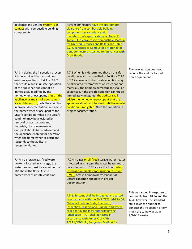
7.4.2 ….Determine whether the 7.7.2 Determine whether the appliance and The new version provides specific clearances.
5
appliance and venting system is in contact with combustible building components.
its vent connectors have the appropriate clearance from combustible building components in accordance with manufacturer’s specifications or Annex E, Table E.1, Clearances to Combustible Material for Unlisted Furnaces and Boilers and Table E.2, Clearances to Combustible Material for Vent Connectors Attached to Appliances with Draft Hoods.
7.4.3 If during the inspection process it is determined that a condition exists as specified in 7.4.1 or 7.4.2 that could result in unsafe operation of the appliance and cannot be immediately modified by the homeowner or occupant, shut off the appliance by means of a consumer‐accessible control, note the condition in project documentation, and advise the homeowner or occupant of the unsafe condition. Where the unsafe condition may be alleviated by removal of obstructions and materials, the homeowner or occupant should be so advised and the appliance enabled for operation when the homeowner or occupant responds to the auditor’s recommendation.
7.7.3 When it is determined that an unsafe condition exists, as specified in Sections 7.7.1 – 7.7.2 above, and the unsafe condition may be alleviated by removal of obstructions and materials, the homeowner/occupant shall be so advised. If the unsafe condition cannot be immediately mitigated, the auditor shall advise the homeowner/occupant that the appliance should not be used until the unsafe condition is mitigated. Note the condition in project documentation.
The new version does not require the auditor to shut down equipment.
7.4.4 If a storage gas‐fired water heater is located in a garage, the water heater must be a minimum of 18” above the floor. Advise homeowner of unsafe condition.
7.7.4 If a gas or oil‐fired storage water heater is located in a garage, the water heater must be a minimum of 18” above the floor unless listed as flammable vapor ignition resistant (FVIR). Advise homeowner/occupant of unsafe condition and note in project documentation.
7.5.1. Systems shall be inspected and tested in accordance with the ANSI Z223.1/NFPA 54, National Fuel Gas Code, Chapter 8, Inspection, Testing, and Purging, and where called for by the local authority having jurisdiction (AHJ), shall be tested in accordance with Annex C of ANSI Z223.1/NFPA 54, Suggested Method for
This was added in response to comments from NFPA and the AGA. however the standard still allows the auditor to conduct the inspection pretty much the same way as in 9/26/13 version.

6
Checking for Leakage.
Alternatively, the auditor shall
conduct the following inspection tasks
7.5.1.2.2. Move the wand in a 360‐degree circle around the entire joint at a rate of 1” per second.
7.5.2.2.2. Move the CGD wand along the entire gas line at a rate of 1″ per second with the tip above the line for natural gas and below for LP gas. Move the CGD wand in a 360‐degree circle completely around each joint at a rate of 1” per second.
This addition makes it clear that the auditor must test the entire line, not just the joints.
7.5.1.3 The gas leakage inspection shall include the following components:
7.5.1.3.1 All accessible gas piping fittings from the outlet of the natural gas meter or LP tank to a point where the supply line connects to the gas valve of all appliances. Do not move appliances.
7.5.1.3.2 Appliance gas valve/regulator housing and connections
7.5.2.3 The gas leakage inspection shall include the following components:
7.5.2.3.1 The entire gas line and all accessible gas piping fittings from the outlet of the natural gas meter or LP gas tank to a point where the supply line connects to the gas valve of all appliances. Do not move appliances.
7.5.2.3.2 Appliance gas valve/regulator housing and connections.
Same as above
7.5.2.4 Where gas leakage is confirmed, the site shall be marked and the homeowner/occupant shall be notified that repairs should be made. The auditor shall recommend that the homeowner/occupant immediately notify the gas company and/or a qualified professional to evaluate and perform all necessary repairs.
7.5.2.42 The auditor shall contact the appropriate emergency services only if the homeowner/occupant is unable to do so
The previous version of the standard required the auditor to make the call. The new version has the auditor recommend that the homeowner make the call. The auditor makes the call only in the case where the homeowner is unable to do so.
7.5.1.5 When the CGD indicates that combustible gas exists in the ambient atmosphere (at any level) and a gas leak cannot be confirmed after completing the inspection above, the auditor shall inform the occupants and alert the fuel supplier.
7.5.2.5 When the CGD indicates that combustible gas exists in the ambient atmosphere (at any level below 10% of LEL) and a gas leak cannot be confirmed with the use of leak detection solution, the auditor shall inform the homeowner/occupants and advise the homeowner/occupant to notify the gas company and/or a qualified professional.
Added for clarification. If the level was over 10% of LEL, the action level would be different. Also note (as above) that the new version of the standard has the homeowner/occupant contacting the gas company or qualified professional, not the auditor. This is the same
7
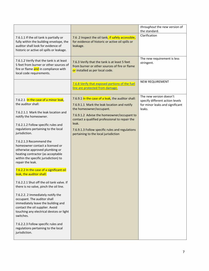
throughout the new version of the standard.
7.6.1.1 If the oil tank is partially or fully within the building envelope, the auditor shall look for evidence of historic or active oil spills or leakage.
7.6 .2 Inspect the oil tank, if safely accessible, for evidence of historic or active oil spills or leakage.
Clarification
7.6.1.2 Verify that the tank is at least 5 feet from burner or other sources of fire or flame and in compliance with local code requirements.
7.6.3 Verify that the tank is at least 5 feet from burner or other sources of fire or flame or installed as per local code.
The new requirement is less stringent.
7.6.8 Verify that exposed portions of the fuel line are protected from damage.
NEW REQUIREMENT
7.6.2.1 In the case of a minor leak, the auditor shall:
7.6.2.1.1 Mark the leak location and notify the homeowner.
7.6.2.1.2 Follow specific rules and regulations pertaining to the local jurisdiction.
7.6.2.1.3 Recommend the homeowner contact a licensed or otherwise approved plumbing or heating contractor (as acceptable within the specific jurisdiction) to repair the leak.
7.6.2.2 In the case of a significant oil leak, the auditor shall:
7.6.2.2.1 Shut off the oil tank valve. If there is no valve, pinch the oil line.
7.6.2.2. 2 Immediately notify the occupant. The auditor shall immediately leave the building and contact the oil supplier. Avoid touching any electrical devices or light switches.
7.6.2.2.3 Follow specific rules and regulations pertaining to the local jurisdiction.
7.6.9.1 In the case of a leak, the auditor shall:
7.6.9.1.1 Mark the leak location and notify the homeowner/occupant.
7.6.9.1.2 Advise the homeowner/occupant to contact a qualified professional to repair the leak.
7.6.9.1.3 Follow specific rules and regulations pertaining to the local jurisdiction
The new version doesn’t specify different action levels for minor leaks and significant leaks.
8
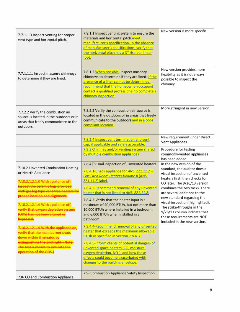
7.7.1.1.3 Inspect venting for proper vent type and horizontal pitch.
7.8.1.1 Inspect venting system to ensure the materials and horizontal pitch meet manufacturer’s specification. In the absence of manufacturer’s specifications, verify that the horizontal pitch has a ¼” rise per linear foot.
New version is more specific.
7.7.1.1.1. Inspect masonry chimneys to determine if they are lined.
7.8.1.2 When possible, inspect masonry chimneys to determine if they are lined. If the presence of a liner cannot be determined, recommend that the homeowner/occupant contact a qualified professional to complete a chimney inspection.
New version provides more flexibility as it is not always possible to inspect the chimney.
7.7.2.2 Verify the combustion air source is located in the outdoors or in areas that freely communicate to the outdoors.
7.8.2.2 Verify the combustion air source is located in the outdoors or in areas that freely communicate to the outdoors and in a code compliant location.
More stringent in new version.
7.8.2.4 Inspect vent termination and vent cap, if applicable and safely accessible.
New requirement under Direct Vent Appliances
7.8.3 Chimney and/or venting system shared by multiple combustion appliances
Procedure for testing commonly‐vented appliances has been added.
7.10.2‐Unvented Combustion Heating or Hearth Appliance
7.10.2.1.2.1.3‐With appliance off, inspect the ceramic logs provided with gas log type vent‐free heaters for proper location and alignment.
7.10.2.1.2.1.4‐With appliance off, verify that oxygen depletion system (ODS) has not been altered or bypassed.
7.10.2.1.2.1.4‐With the appliance on, verify that the main burner shuts down within 3 minutes by extinguishing the pilot light. (Note: The test is meant to simulate the operation of the ODS.)
7.8.4 [ Visual Inspection of] Unvented heaters
7.8.4.1‐Check appliance for ANSI Z21.11.2 –Gas Fired Room Heaters‐Volume II (ANSI Z21.11.2) label.
7.8.4.2‐Recommend removal of any unvented heater that is not listed to ANSI Z21.11.2.
7.8.4.3‐Verify that the heater input is a maximum of 40,000 BTUh, but not more than 10,000 BTUh where installed in a bedroom, and 6,000 BTUh when installed in a bathroom.
7.8.4.4‐Recommend removal of any unvented heater that exceeds the maximum allowable BTUh as specified in Section 7.8.4.3.
7.8.4.5‐Inform clients of potential dangers of unvented space heaters (CO, moisture, oxygen depletion, NO2), and how these effects could become exacerbated with changes to the building envelope.
In the new version of the standard, the auditor does a visual inspection of unvented heaters first, then checks for CO later. The 9/26/13 version combines the two tasks. There are several additions to the new standard regarding the visual inspection (highlighted). The strike‐throughs in the 9/26/13 column indicate that these requirements are NOT included in the new version.
7.8‐ CO and Combustion Appliance 7.9‐ Combustion Appliance Safety Inspection

9
Zone Tests
7.8.1.1‐ Ambient CO shall be monitored at all times during the test. If measured CO levels exceed 35 ppm as measured at any time during the test, testing shall stop, the appliance shut down, and a recommendation shall be made to the homeowner for a service technician to be contacted to diagnose and repair the problem before any other testing is completed.
7.9. Ambient CO shall be monitored at all
times during the test and actions taken as
per Section 7.3.3.3 of this document.
In the new version, the inspection is terminated if ambient CO levels reach 70 ppm or greater. (See Section 7.3.3.3 for further details.)
7.8.1.2‐ Close fireplace dampers and any fireplace doors. Close all building exterior doors and windows. Close all CAZ doors. Close the interior door of all rooms except for rooms with an exhaust fan and rooms with a central forced air system return.
7.9.1.2‐Fires in woodstoves and/or fireplaces shall be fully extinguished, with no hot coals or embers, prior to performing a depressurization test. Close fireplace dampers and any fireplace doors.
7.9.1.3‐Close all building exterior doors and windows. Close all CAZ doors. Close the interior doors of all rooms except for rooms with an exhaust fan and rooms with a central forced air system return. Outdoor openings for combustion air shall remain open.
7.8.1.4‐Using a calibrated manometer or similar pressure measuring device intended for this purpose, measure and record the pressure in the space where the combustion appliance is located with reference to (WRT) outside.
7.9.1.5‐Using a calibrated manometer or similar pressure measuring device intended for this purpose, measure and record the baseline pressure in the CAZ with reference to (WRT) outside. Compare this measurement with subsequent pressure measurements to determine the greatest negative pressure achievable in the CAZ.
Added for clarification
7.8.1.5 ‐Turn on the following exhaust equipment: clothes dryers (check and clean the dryer filter prior to operation), range hoods, and bathroom exhaust fans. If there are speed controls, operate the exhaust equipment at the highest speed setting. Do not operate a whole house cooling exhaust fan.
7.9.1.6‐ Turn on the following exhaust equipment: clothes dryers (check and clean the dryer filter and look for blockage at the external vent damper prior to operation), range hoods, and other exhaust fans. If there are speed controls, operate the exhaust equipment at the highest speed setting. Do not operate a whole house cooling exhaust fan.
7.8.1.8 ‐Open all doors between the CAZ and other spaces of the building. Measure and record the pressure in
7.9.1.9 ‐Open interior door/s directly leading to the CAZ. Measure and record the pressure in the CAZ WRT outside.

10
the space where the appliance is located WRT outside.
7.9.1.9.1 3Footnote added to new version allowing pressure diagnostics: Alternatively, pressure differential diagnostics may be used to determine proper door configuration to create the greatest CAZ depressurization. Pressure differential diagnostics may include manometer readings or a visual indicator, such as smoke.
7.8.1.11 Cold Vent (Except Domestic Water Heaters) Spillage shall be assessed and CO Air Free measurement of undiluted flue gas shall be taken at 1 minute of main burner operation and again at 1 minute intervals for 5 minutes. 1If based on the interview of the
homeowner or visual inspection of the appliance, a determination is made that the appliance needs to be serviced, the auditor may specify service by a qualified professional in lieu of performing the Air Free CO testing as specified in Section 7.8.1.11.The auditor must perform the spillage tests as specified in Section 7.8.1.11 and Section 7.8.1.12
See Section 7.9.2 re Cold Vent
7.9.2.1 Spillage shall be assessed at 5 minutes of main burner operation. 7.9.2.1 CO measurement of undiluted flue gas shall be taken at 5 minutes of main burner operation
For cold vents, the new version has the auditor assess spillage and measure CO in undiluted flue gases at 5 minutes of main burner only. No repeated measurements as in the original version. Actions levels for the new version are provided in Annex D and they differ substantively from the original version regarding spillage. The new version does not include the footnote that allows an auditor to skip the CO testing.
7.8.1.12 Domestic Water Heaters or Warm Vent. Spillage shall be assessed and CO Air Free measurement of undiluted flue gas shall be taken at 1 minute of main burner operation and again at 2 minutes. CO Air‐Free measurement of undiluted flue gas shall continue to be taken at 1 minute intervals for a total of 5 minutes. 1 If based on the interview of the homeowner or visual inspection of the appliance, a determination is made that the appliance needs to be serviced, the auditor may specify service by a qualified professional in lieu of performing the Air Free CO testing as specified in Section 7.8.1.12. The auditor must perform the spillage tests as specified in Section 7.8.1.12
See Section 7.9.3 re Domestic Water Heaters and Warm Vent
7.9.3.1 Spillage shall be assessed at 2 minutes of main burner operation.
7.9.3.2 CO measurement of undiluted flue gas shall be taken at 5 minutes of main burner operation
The new version gets rid of repeated measurement. Spillage is assessed at 2 minutes and CO is assessed at 5 minutes. Actions levels for the new version are provided in Annex D and they differ substantially from the original version regarding spillage. The new version does not include the footnote that allows an auditor to skip the CO testing.
7.9.4 Multiple combustion appliances The new version provides a protocol for testing multiple combustion appliances that share a chimney and/or venting system.
Table 7.8.5 CO Thresholds Table 7.9.5 CO Thresholds The new version of the table specifies that the thresholds

11
pertain to fossil‐fuel fired appliances. Also, a typo was corrected from Oven/Boiler to Oven/Broiler.
7.9‐ If the outlet of the exhaust is accessible, include a CO test on all direct vented and power‐vented appliances (without atmospheric chimneys).
7.9.6.1‐If the outlet of the exhaust is safely accessible, measure the CO level in the undiluted flue gas on all direct‐vented and power‐vented appliances (without atmospheric chimneys or vents) at 5 minutes of main burner operation.
7.9.6.2‐The CO measurement/s shall be compared with the appropriate CO threshold/s in Section 7.9.5, Table 1.
7.9.6.3‐Action levels for CO exceeding the appropriate threshold/s in Section 7.9.5, Table 1 shall be taken in accordance with Annex D, Table D.1.B.
Additional detail provided in new version.
7.10.1 Combustion Cooking Appliances
7.9.7. Gas Ovens and Range Tops
Please see Section 7.9.7. Provides a testing protocol to be used in the absence of manufacturer’s appliance procedure.
The 9/26/13 version referencesthe procedure in the BA standards. The new version does not. The new version does NOT require CO testing of range top burners. The 9/26/13 version did require it. The new version includes more details.
7.11‐ Inspect solid fuel burning appliances for safe operation.
This section, in its entirety, has been moved to informative Annex J in the new (5/18/15) version.
7.10‐ Solid fuel burning appliance inspection
This is now a simplified visual inspection as compared to the 9/26/13. The more complex procedure that was included in the 9/26/13 version is now provided in Annex J as an alternative.
7.7.3. Return all inspected appliances and systems to their pre‐existing state by reinstalling any removed access panels and components.
7.11 Placing Appliances Back in Operation
If no safety concerns or hazards were identified during the inspection of the combustion appliances, return all inspected appliances and systems to their pre‐existing state. If appliance‐related safety concerns or hazards were identified during the inspection, follow the appropriate actions levels specified in the preceding Sections. Note: In some cases this will require that the auditor recommend that the appliance be turned off and the homeowner/occupant be advised to
This requirement has been moved to the end of Section 7 in the new standard. It’s been substantively revised for clarification.

12
contact a qualified professional for further evaluation.
SECTION 10Building Enclosure
9/26/13 Version 5/18/15 Version Notes
Section 10 ‐ Building Enclosure Performance
Section 10 – Building Enclosure New version requires the auditor to gather additional information; the significant additions are detailed below.
10.1.1.1 Changes highlighted in next column.
10.1.1.1.When assessing components of the building enclosure for cost‐benefit analysis and prioritization, detailed measurements of components and insulation levels are optional. However, specific home energy upgrades that are recommended for action shall include adequate detail to ensure accurate savings estimates, including quantity, surface area, construction type, existing listed R‐value (if available), effective R‐value, and proposed modifications.
Clarification
10.1.1.2‐Throughout the evaluation, note the presence of hazards or potential hazards such as knob and tube wiring
NEW REQUIREMENT
10.1.2.1 Note the foundation type(s) (e.g., slab on grade, crawl space, basement), construction type (e.g., stone, brick, poured concrete), location of the thermal boundary, and exposure above grade. Note whether there is finished, occupied space in any basement(s).
10.1.2.1 Note the foundation type(s) (e.g., slab on grade, crawl space, basement), construction type (e.g., stone, brick, poured concrete), location of the thermal boundary, and exposure above grade. When feasible, note location and condition of the pressure boundary and the moisture barrier.
Note that the “when feasible …” clause is seen throughout Section 10 in the new version.
10.1.2.6 ‐When ECM(s) for foundation insulation are proposed, indicate the surface area(s), thickness and type of insulation, and construction type along with the scope of proposed ECM installation for each.
10.1.2.5 When home energy upgrades for foundation insulation are proposed, indicate the surface area(s) and construction type, recommended effective R‐value, and the thickness, type and performance characteristics (e.g., perm rating) of insulation. Insulation recommendations shall be based on the building’s moisture barrier, thermal barrier, air barrier, and drainage plane (as applicable).
Rewording for clarification. Additional detail requires more documentation by the auditor.
13
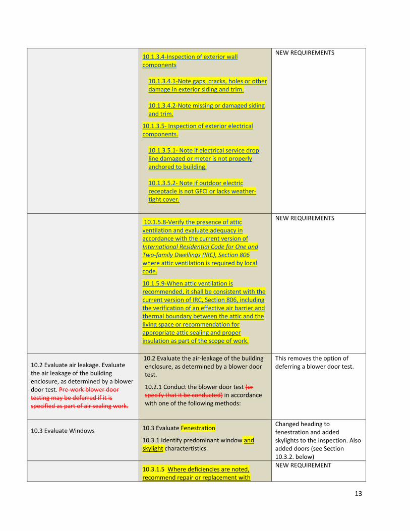
10.1.3.4‐Inspection of exterior wall components
10.1.3.4.1‐Note gaps, cracks, holes or other damage in exterior siding and trim.
10.1.3.4.2‐Note missing or damaged siding and trim.
10.1.3.5‐ Inspection of exterior electrical components.
10.1.3.5.1‐ Note if electrical service drop line damaged or meter is not properly anchored to building.
10.1.3.5.2‐ Note if outdoor electric receptacle is not GFCI or lacks weather‐tight cover.
NEW REQUIREMENTS
10.1.5.8‐Verify the presence of attic ventilation and evaluate adequacy in accordance with the current version of International Residential Code for One and Two‐family Dwellings (IRC), Section 806 where attic ventilation is required by local code.
10.1.5.9‐When attic ventilation is recommended, it shall be consistent with the current version of IRC, Section 806, including the verification of an effective air barrier and thermal boundary between the attic and the living space or recommendation for appropriate attic sealing and proper insulation as part of the scope of work.
NEW REQUIREMENTS
10.2 Evaluate air leakage. Evaluate the air leakage of the building enclosure, as determined by a blower door test. Pre‐work blower door testing may be deferred if it is specified as part of air sealing work.
10.2 Evaluate the air‐leakage of the building enclosure, as determined by a blower door test.
10.2.1 Conduct the blower door test (or specify that it be conducted) in accordance with one of the following methods:
This removes the option of deferring a blower door test.
10.3 Evaluate Windows 10.3 Evaluate Fenestration
10.3.1 Identify predominant window and skylight charactertistics.
Changed heading to fenestration and added skylights to the inspection. Also added doors (see Section 10.3.2. below)
10.3.1.5 Where deficiencies are noted, recommend repair or replacement with
NEW REQUIREMENT

14
windows that meet or exceed ENERGY STAR®
specifications.
10.3.2 Evaluate exterior door characteristics
10.3.2.1 Determine whether the door is insulated.
10.3.2.2 Determine whether the door is wood, metal, or fiberglass.
10.3.2.3. Inspect for missing or damaged caulking around door frame; missing or damaged trim or door components; visible air leaks. Note if door does not open, close or lock properly.
10.3.2.4 Where deficiencies are noted, recommend repair or replacement with doors that meet or exceed ENERGY STAR® specifications. When home energy upgrades for one or more door(s) are proposed, indicate both the surface areas and characteristics of each existing door.
NEW REQUIREMENTS
SECTION 11Heating, Cooling and Domestic Water Heating Systems
9/26/13 Version 5/18/15 Version Notes
Section 11 ‐ Heating and Cooling (HVAC) and Domestic Water Heating Performance and Efficiency
Section 11 – Heating, Cooling, and Domestic Water Heating Systems Performance and Efficiency
Note the title change for this section. This is (for the most part) a visual inspection. Auditors are not required to do any performance testing. The term “Performance and Efficiency” has also been removed from sub‐section titles throughout Section 11.
Section 11.1 General Requirements
This sub‐section was added up front to eliminate redundancies throughout the rest of Section 11.
11.1.1‐Locate and record the appliance brand, model, model number, operating specifications such as BTU input and BTU output, listed temperature rise, and Total External Static Pressure.
11.1.4‐ For each heating appliance and domestic water heater listed in Section 11, locate and record the system information from the nameplate when available and as applicable to the individual appliance: appliance brand, model, model number, size in BTUh, operating specifications such as the efficiency rating, if available, BTUh input and BTUh output, listed temperature rise, and listed maximum external static pressure.
Some changes and additions to the info needed from the appliance nameplate. Note the correction from Total External Static Pressure to listed maximum external static pressure. (The auditor is not required to do a total external static pressure test.)

15
11.1.4‐ Note the condition of the system filter slot cover. If no filter slot cover exists or is in poor condition, make recommendation to install/replace.
11.2.4‐Note the condition of the system filter slot cover. If no filter slot cover exists, is in poor condition, or is not well‐sealed to prevent air infiltration / exfiltration between the HVAC system and the equipment room, make recommendation to install/replace.
Additional detail
11.1.5 Determine when the appliance was last serviced. If the appliance has not been serviced within the past two years, recommend a complete service including a steady state efficiency test by a qualified technician be conducted.
11.1.1 For all appliances included in Section 11 with the exception of domestic water heaters, determine when the appliance was last serviced. If the appliance has not been serviced within the past two years, recommend servicing by a qualified technician professional as specified in ANSI/ACCA 4‐2013: Maintenance of Residential HVAC Systems (ANSI/ACCA 4 QM), or the manufacturer’s instructions, or by procedures accepted by AHJ.
Provides details regarding the service to be specified. Note: “technician” has been replaced with “professional” throughout Section 11.
(Re A/C and Heat Pump)
11.2.1‐Note the system information from the data plate including brand, model, model number, refrigerant type and efficiency, if available.
11.1.5‐‐For each cooling appliance listed in Section 11, note the system information from the nameplate when available, and as applicable to the individual appliance: appliance brand, model, model number, capacity or size in BTUh, refrigerant type, and efficiency, if available. Record listed maximum external static pressure if available on the air handler unit or in furnace specifications.
Additional info to be collected from nameplate.
11.2.6‐If furnace model allows for condensing operation, check the condition of condensate drain connections, drain line and the condition of the condensate pump if one exists. If no drain line exists, signs of condensate leakage on cabinet are apparent or the condensate pump shows signs of failure such as: the pump reservoir is leaking; the pump or condensate lines are clogged; or the pump is inoperative, rusted, cracked or has suffered mechanical damage, or otherwise appears to be in poor condition, recommend that it be serviced by a qualified professional.
NEW REQUIREMENT
16
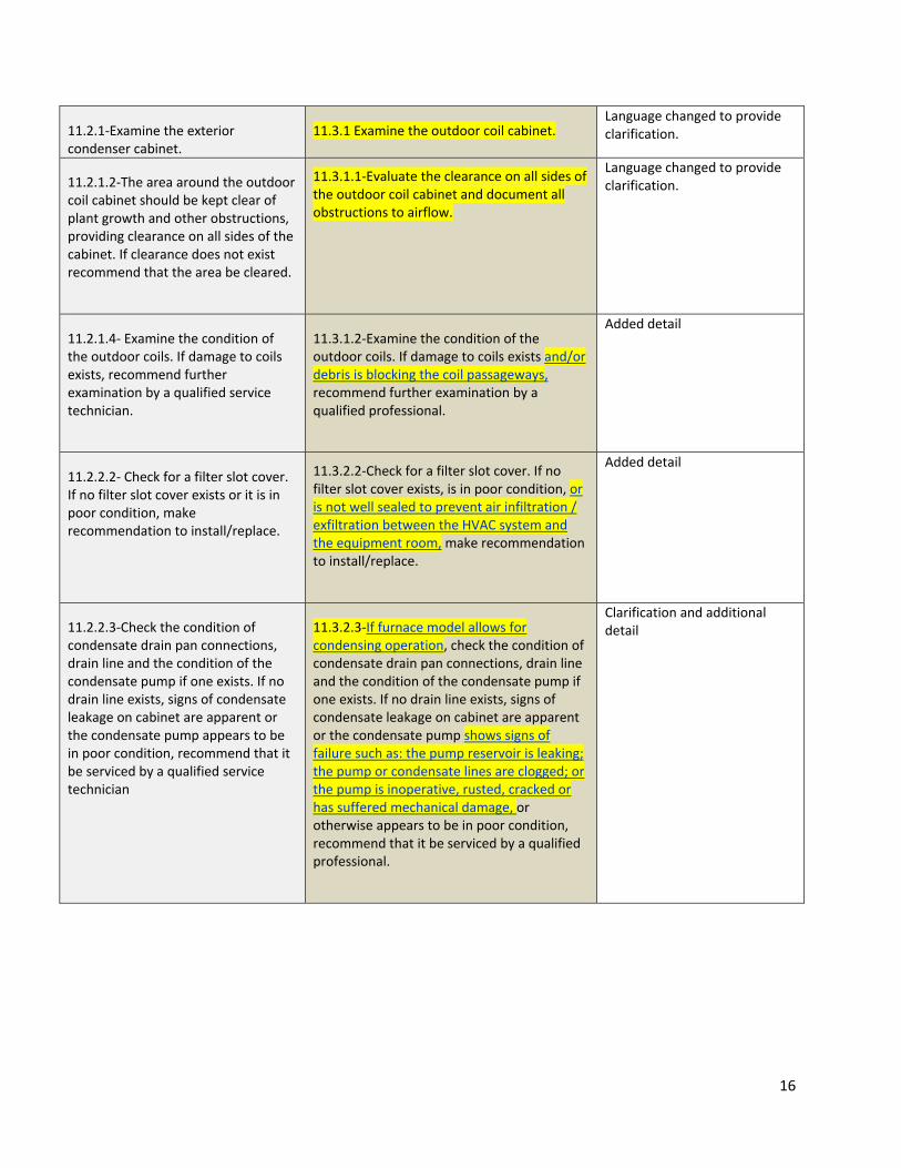
11.2.1‐Examine the exterior condenser cabinet.
11.3.1 Examine the outdoor coil cabinet. Language changed to provide clarification.
11.2.1.2‐The area around the outdoor coil cabinet should be kept clear of plant growth and other obstructions, providing clearance on all sides of the cabinet. If clearance does not exist recommend that the area be cleared.
11.3.1.1‐Evaluate the clearance on all sides of the outdoor coil cabinet and document all obstructions to airflow.
Language changed to provide clarification.
11.2.1.4‐ Examine the condition of the outdoor coils. If damage to coils exists, recommend further examination by a qualified service technician.
11.3.1.2‐Examine the condition of the outdoor coils. If damage to coils exists and/or debris is blocking the coil passageways, recommend further examination by a qualified professional.
Added detail
11.2.2.2‐ Check for a filter slot cover. If no filter slot cover exists or it is in poor condition, make recommendation to install/replace.
11.3.2.2‐Check for a filter slot cover. If no filter slot cover exists, is in poor condition, or is not well sealed to prevent air infiltration / exfiltration between the HVAC system and the equipment room, make recommendation to install/replace.
Added detail
11.2.2.3‐Check the condition of condensate drain pan connections, drain line and the condition of the condensate pump if one exists. If no drain line exists, signs of condensate leakage on cabinet are apparent or the condensate pump appears to be in poor condition, recommend that it be serviced by a qualified service technician
11.3.2.3‐If furnace model allows for condensing operation, check the condition of condensate drain pan connections, drain line and the condition of the condensate pump if one exists. If no drain line exists, signs of condensate leakage on cabinet are apparent or the condensate pump shows signs of failure such as: the pump reservoir is leaking; the pump or condensate lines are clogged; or the pump is inoperative, rusted, cracked or has suffered mechanical damage, or otherwise appears to be in poor condition, recommend that it be serviced by a qualified professional.
Clarification and additional detail

17
11.2.3 11.3.3‐Check the integrity of the accessible refrigerant piping insulation in the interior of the building. If no insulation exists on the larger refrigeration line or it is in poor condition, recommend that piping insulation be installed/replaced by a qualified professional.
Clarification
11.2.5‐If a humidifier has been added to the system and is not used, recommend that it be removed and the ducting sealed in accordance with ANSI/BSR BPI‐3300‐A‐201x Standard for Residential Building Air Distribution System Energy Performance Applications.
11.3.5‐If a humidifier has been added to the system and is not used, recommend that it be removed and the ducting sealed in accordance with ANSI/BSR BPI‐3300‐A‐201x Standard for Residential Building Air Distribution System Energy Performance Applications.. If the humidifier has not been used due to operational issues, recommend that it be repaired by a qualified professional.
The reference to BPI‐3300 was removed because that standard has not yet been published as an ANSI standard. Last sentence added for clarification.
11.3.1‐Examine the exterior condenser cabinet per 11.2.1
11.4.1‐Examine the exterior condenser outdoor coil cabinet per 11.3.1
Language changed for clarification.
11.4.3‐Examine the refrigerant piping insulation per 11.3.3.
11.4.4‐Examine the inside of the air handler cabinet per 11.3.4.
NEW REQUIREMENTSInadvertently omitted from previous version.
11.4.2‐ Examine the condition and the installation of the air conditioner, verifying the condition of the air sealing around the perimeter. If unit is not air sealed, recommend installation/repairs.
11.5.1‐ Examine the condition and the installation of the packaged terminal air conditioner, verifying the condition of the air sealing around the perimeter. If unit is not air sealed or air sealing is in poor condition, recommend installation/repairs.
Clarification
11.5 ‐Evaluate duct performance of air distribution systems in accordance with:
11.5.1‐ANSI/BSR BPI‐3300‐T‐201x Standard for Residential Building Air Distribution System Energy Performance, Sections 5.2 and 7
Or
11.5.2‐In accordance with procedures from ANSI/ACCA 5 QI‐2010 ‐ HVAC
11.6 ‐Evaluate the air distribution system. Complete an inspection of the air distribution system and document information as noted in this section.
PLEASE REVIEW SECTION 11.6 IN ITS ENTIRETY (PAGES 24‐26) TO SEE HOW IT DIFFERS FROM THE 9‐26‐13 VERSION. TOO MANY CHANGES TO INCLUDE IN THIS FORMAT.
Rather than referencing BPI‐3300, sub‐section 11.6 now spells out how to conduct the evaluation delineates quantitative and qualitative duct leakage testing.

18
Quality Installation Specification, Section 5.1 Duct Leakage
11.7 Evaluate steam‐heating boiler performance and efficiency. The auditor shall complete a visual
inspection of the forced hot water or
steam‐heating boiler and document
information as noted in this section.
11.7.1‐ Locate and record the appliance brand, model number, operating specifications such as BTU input and BTU output.
11.7.2‐Inspect for evidence of leakage at the appliance and local piping.
11.8‐Evaluate steam‐heating system. Complete a visual inspection of the steam‐heating boiler and document information as noted in this section.
11.8.1‐Inspect for evidence of water leakage, build‐up of deposits, and/or corrosion at the appliance and local piping. If such evidence is noted, recommend further evaluation and/or repair by a qualified professional.
11.8.2‐Check sight glass and note water level and appearance. If no water is present or the water level is at or near the bottom of the sight glass, or if the water is dark in color, recommend that the system be serviced by a qualified professional.
11.8.3‐Determine through homeowner/occupant interview if water had to be added to or removed from the boiler during the heating season. If water has been added or removed, recommend that the system be serviced by a qualified professional.
11.8.4‐Verify presence of a low water cutoff. If no low water cut‐off is present, recommend installation by a qualified professional.
11.8.5‐Verify the presence of the temperature/pressure relief (TPR) valve and note its rating. Verify the presence of TPR piping. If TPR valve and/or piping for relief valve are missing, or the valve is improperly rated for the appliance, recommend installation by a qualified professional.
11.8.6‐Inspect for soot, debris, or signs of spillage around flue collar, barometric draft control, or draft hood if the appliance is equipped with one. If noted, recommend that the system be serviced by a qualified professional.
More detail and NEW REQUIREMENTS provided in current version.
11.8‐ Evaluate steam‐heating distribution performance.
The auditor shall complete a visual
11.9‐Evaluate the steam‐heating distribution system. Complete a visual inspection and document information as noted in this
More detail and NEW REQUIREMENTS provided in the current version.

19
inspection and document information
as noted in this section.
11.9.1‐Examine the insulation on the steam‐heating distribution piping. Many of the older steam distribution systems used asbestos to insulate the piping. If friable asbestos‐like material is evident, the audit report shall include a recommendation for a qualified professional to verify the presence of asbestos and encapsulate or remove it. If no insulation exists, recommend that piping be insulated with insulation rated for steam piping.
section.
11.9.1‐Examine the insulation on the steam‐heating distribution piping. Note the insulation type and condition. If friable asbestos‐like material is evident, project documentation shall include a recommendation for a qualified professional to verify the presence of asbestos and that procedures follow federal, state and local guidelines for dealing with asbestos. On systems with no insulation or damaged insulation, recommend that piping be insulated with insulation rated for steam piping or to a level meeting the requirements of the AHJ.
11.9.2‐Determine through observation or homeowner/occupant interview if unusual noises are heard from the distribution system while the system is operating. If noted, recommend further evaluation by a qualified professional.
11.9.3‐Inspect the distribution system for water leaks. If leaks are noted, recommend repair by a qualified professional.
11.9.4‐Inspect for missing or damaged vents on radiators. Note deficiencies and recommend further evaluation/repair by a qualified professional.
11.9.5‐Follow lighting instructions for boiler and place in operation. Adjust the thermostat or control so the appliance will operate continuously. Note any radiators not producing heat. If any radiator does not produce heat, recommend the system be serviced by a qualified professional. Place boiler control to original setting.
11.9‐Evaluate forced hot‐water space heating appliance performance and efficiency. The auditor shall complete a visual
inspection of the forced hot water or
steam‐heating boiler and document
information as noted in this section.
11.9.1‐Locate and record the appliance brand, model number,
11.10‐Evaluate the forced hot‐water space heating appliance. Complete a visual inspection of the forced hot water space heating appliance and document information as noted in this section.
11.10.1‐Inspect for evidence of leakage, corrosion and deposits at the appliance and local piping. If such evidence is noted, recommend further evaluation and/or
More detail and NEW REQUIREMENTS) provided in current version.

20
operating specifications such as BTU input and BTU output.
11.9.2‐Inspect for evidence of leakage at the appliance and local piping.
repair by a qualified professional.
11.10.2‐Verify presence of an automatic feeder valve. If not present, recommend installation by a qualified professional. Determine through homeowner/occupant interview if water had to be added to or removed from the appliance during the heating season. If water was added or removed, recommend that the system be serviced by a qualified professional.
11.10.3‐Verify the presence of the TPR valve and note its rating. Verify the presence of TPR piping. If TPR valve and/or piping for relief valve are missing, or the valve is improperly rated for the appliance, recommend installation by a qualified professional.
11.10.4‐Verify the presence of a low water cut‐off. If no low water cut‐off is present, recommend installation by a qualified professional.
11.10.5‐Inspect for soot, debris, or signs of spillage around flue collar, barometric draft control, or draft hood. If noted, recommend boiler be serviced by a qualified professional.
11.10.6‐Note condition of the expansion tank. If it is in poor condition (e.g., corrosion or pitting), recommend further evaluation and/or replacement by a qualified professional.
11.10‐Evaluate forced hot‐water space‐heating distribution performance. The auditor shall complete a visual
inspection and document information
as noted in this section.
11.10.1‐Document the number and location of circulating pumps on forced‐water systems.
11.10.2‐Check the fin tubes of the convectors for built up dust or other restrictions.
11.10.3‐Survey the distribution
11.11‐Evaluate forced hot‐water space‐heating distribution system. Complete a visual inspection and document information as noted in this section.
11.11.1‐Document the number and location of circulating pumps and/or zone valves and location of the thermostats/operating controls for each pump/zone.
11.11.2‐Inspect the fin tubes of the heat emitters, if equipped, for built up dust or obvious obstructions. If dust or obstruction are noted, recommend fin tubes be cleaned. Note any closed dampers and discuss with homeowner/occupant.
Clarification, additional detail and a few NEW REQUIREMENTS provided in the current version.
21
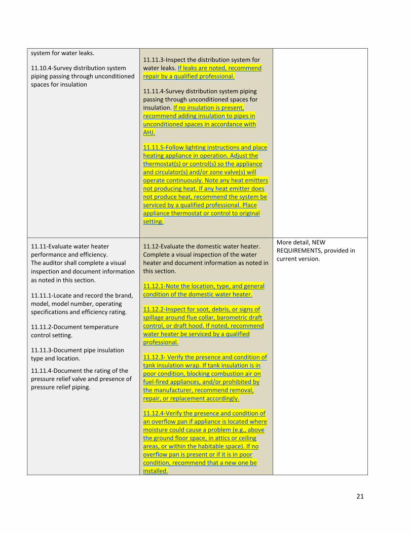
system for water leaks.
11.10.4‐Survey distribution system piping passing through unconditioned spaces for insulation
11.11.3‐Inspect the distribution system for water leaks. If leaks are noted, recommend repair by a qualified professional.
11.11.4‐Survey distribution system piping passing through unconditioned spaces for insulation. If no insulation is present, recommend adding insulation to pipes in unconditioned spaces in accordance with AHJ.
11.11.5‐Follow lighting instructions and place heating appliance in operation. Adjust the thermostat(s) or control(s) so the appliance and circulator(s) and/or zone valve(s) will operate continuously. Note any heat emitters not producing heat. If any heat emitter does not produce heat, recommend the system be serviced by a qualified professional. Place appliance thermostat or control to original setting.
11.11‐Evaluate water heater performance and efficiency. The auditor shall complete a visual
inspection and document information
as noted in this section.
11.11.1‐Locate and record the brand, model, model number, operating specifications and efficiency rating.
11.11.2‐Document temperature control setting.
11.11.3‐Document pipe insulation type and location.
11.11.4‐Document the rating of the pressure relief valve and presence of pressure relief piping.
11.12‐Evaluate the domestic water heater. Complete a visual inspection of the water heater and document information as noted in this section.
11.12.1‐Note the location, type, and general condition of the domestic water heater.
11.12.2‐Inspect for soot, debris, or signs of spillage around flue collar, barometric draft control, or draft hood. If noted, recommend water heater be serviced by a qualified professional.
11.12.3‐ Verify the presence and condition of tank insulation wrap. If tank insulation is in poor condition, blocking combustion air on fuel‐fired appliances, and/or prohibited by the manufacturer, recommend removal, repair, or replacement accordingly.
11.12.4‐Verify the presence and condition of an overflow pan if appliance is located where moisture could cause a problem (e.g., above the ground floor space, in attics or ceiling areas, or within the habitable space). If no overflow pan is present or if it is in poor condition, recommend that a new one be installed.
More detail, NEW REQUIREMENTS, provided in current version.

22
11.12.5‐Document temperature control setting.
11.12.6‐Verify the presence of pipe insulation, noting type and location. If no insulation is present, or if existing insulation is in poor condition, recommend insulation be installed on the first six feet of the hot water pipes.
11.12.7‐Verify the presence of the TPR valve and note its rating. Verify the presence of TPR piping. If TPR valve and/or piping for relief valve are missing, or the valve is improperly rated for the appliance, recommend installation by a qualified professional.
11.12.8‐Inspect for leaks at the storage tank. If leaks are evident, recommend that the appliance be replaced with a high efficiency appliance installed by a qualified professional.
SECTION 12Baseload Energy Efficiency
9/26/13 Version 5/18/15 Version Notes
12. Baseload Energy Efficiency and Water Conservation
12. Baseload Energy Efficiency The new version breaks out the Baseload section from the Water Conservation section.
12.2.1‐Record existing refrigerator and freezer model number and date of manufacture. For refrigerators more than 10 years old, recommend replacement with ENERGY STAR® appliances.
12.1.1‐Record existing refrigerator and freezer model number, date of manufacture, and condition. If the model number and date of manufacture cannot be determined, record the type and approximate age for each appliance. When replacement is recommended, recommend replacement appliances that meet or exceed ENERGY STAR® specifications.
Removed the requirement to automatically recommend replacement of appliance more than 10 years old. Adding “meet or exceed” allows more flexibility in selecting new equipment. It doesn’t have to be Energy Star.
12.2.2‐Record type and manufacture date of other appliances such as dishwashers, clothes washers, clothes dryers, dehumidifiers, etc. Based on condition and age of appliances, recommend replacement of appliances with ENERGYSTAR® appliances.
12.1.2‐Record type and manufacture date of other appliances such as dishwashers, clothes washers, clothes dryers, dehumidifiers, etc. If the model number and date of manufacture cannot be determined, record the type and approximate age for each appliance. When replacement is recommended, recommend replacement appliances that
Adding “meet or exceed” allows more flexibility in selecting new equipment. It doesn’t have to be Energy Star.

23
meet or exceed ENERGY STAR®
specifications.
12.2.3‐Record the fuel source and venting of the dryer. Consider replacement of dryer if unit is not equipped with moisture sensing device or if changing to a less expensive fuel source would results in cost savings. Ensure that the dryer vents to the exterior and is not constricted with lint.
12.1.3‐Record the fuel source and venting of the dryer. Consider replacement of dryer if unit is not equipped with moisture sensing device or if changing to a less expensive fuel source would result in cost savings. Ensure that the dryer vents to the exterior and is not constricted with lint. If the dryer is vented with plastic ductwork, recommend replacement with all‐metal ducts.
NEW REQUIREMENT
12.2.5‐Record the types and number of plug loads (for example: televisions, computers, aquariums, phone chargers, etc.). Recommend shutting off or unplugging if not in use, and/or upgrading to ENERGYSTAR® rated units.
12.1.5‐Recommend, and educate homeowner/occupant about, smart power strips for plug load clusters such as an entertainment center or home office, and/or upgrading to units that meet or exceed ENERGYSTAR® specifications.
NEW REQUIREMENT replaces original 12.2.5
12.2.6‐ Record pool and/or spa size, type, and usage. If relevant, recommend a 2 stage pump, operation timers, lower water temperature, solar cover for the pool, thermal cover for the spa, and proper maintenance including cleaning of filters.
12.2.1 Residential pools or inground spas
12.2.1.1‐Record pool and/or spa size (gallons), type, and usage (hours per day and months per year), and existing pump rated horsepower (Hp).
Note: Additional guidance for residential pool and spa inspection can be found in informative Annex H, ANSI/APSP/ICC 15 Energy Efficiency Compliance Information for Residential Swimming Pools.
12.2.1.1‐Where not already in place, recommend a variable speed pool pump that meets or exceeds ENERGY STAR® specifications, operation timers, lower water temperature, solar cover for the pool, and thermal cover for the spa. Recommend proper maintenance including cleaning of filters.
Some changes for clarification, a new reference to APSP‐15 guidance.
12.2.2‐Portable hot tubs NEW REQUIREMENTS specific to portable hot tubs.

24
12.2.2.1‐Verify that the unit is labeled as compliant with minimum standards provided in ANSI/APSP‐14 2011, Standard for Portable Electric Spa Energy Efficiency (ASPS‐14). If the spa is not labeled, recommend replacement with an ASPS‐14‐compliant unit.
12.2.2.2.‐At a minimum, ensure a tight‐fitting and well‐insulated cover to minimize heat loss. If existing insulating cover has become waterlogged, recommend replacement.
12.1.1‐Estimating baseload from measuring energy use
12.4.2‐Estimating baseload from measuring energy use
The current version simplifies/clarifies the language throughout this section.
SECTION 13Water Conservation
9/26/13 Version 5/18/15 Version Notes
12.3.1 13.1‐Record existing quantity and type of shower heads, toilets, faucets, etc. Determine if shower heads and toilets are low‐flow or efficient devices. Determine if faucets are low flow or are equipped with aerators or water conserving design (for example, touch faucets or “WaterSense®” equipped). Note any observed water leaks from plumbing fixtures or leakage at toilet flapper valve/s in project documentation.
Added toilet flapper
13.2‐If home is equipped with old style clothes washer, recommend replacement with an appliance that is equipped with water conserving technology and meets or exceeds ENERGYSTAR® specifications.
Adding “meets or exceeds” allows more flexibility in selecting new equipment. It doesn’t have to be Energy Star.
13.4‐Inspect exterior plumbing components. Note leaking faucets and hose bibs and recommend repair or replacement.
NEW REQUIREMENT