bond that drilling rig
TRANSCRIPT
Bond that Drilling RigPROPERLY!
New performance requirements which clarify what grounding and bonding are required to accomplish March 2014

Purpose of the Grounding System
• Fundamental to the safety of those installing, using, and servicing the electrical system
• Assures the system will work properly while preventing damage to the system
• These are the industry recommend practices and procedures for promotion and maintenance of safe working conditions for personnel engaged in drilling operations and well servicing operations, including special services
Grounding
• The process of making a planned, continuous, connection between NON-CURRENT CARRYING parts of the electrical wiring installation and the earth and some other conducting body

Grounded
• Describes the act of being connected to the earth or some other conduction body that serves in place of the earth
Bonding
• Process in which all NON-CURRENT CARRYING METALLIC parts of the electrical wiring system are permanently joined together to form a CONTINUOUS grounding path
Definitions
Bonding - a low impedance path obtained by permanently joining all non-current carrying metal parts to ensure electrical continuity and having the capacity to conduct safely any current likely to be imposed on it.
Bonding conductor - a conductor that connect the non-current-carrying parts of electrical equipment, raceways, or enclosures to the service equipment or system grounding conductor.
Ground fault circuit interrupter (GFCI) – a device whose function is to interrupt, within a predetermined time, the electrical circuit to the load when a current to ground exceeds a predetermined value that is less than that required to operate the overcurrent protective device of a supply circuit.

Definitions
Ground fault protection – a device, other than a ground fault circuit interrupter of the Class A type, whose function is to control or interrupt ground fault current or voltage-to-ground in the circuit or system where it is installed.
Grounded – connected effectively with the general mass of the earth through a grounding path of sufficiently low impedance and having an ampacity sufficient at all times, under the most severe conditions liable to arise in practice, to prevent any current in the grounding conductor from causing a harmful voltage to exist.a)Between the grounding conductors and neighbouring exposed conducting surfaces that are in good contact with the earth or;b)Between the grounding conductors and neighbouring surfaces of the earth itself.

Definitions
Grounding – a permanent and continuous conductive path to the earth with sufficient ampacity to carry any fault current liable to be imposed on it, and of a sufficiently low impedance to limit the voltage rise above ground and to facilitate the operation of the protective devices in the circuit.
Grounding conductor – the conductor used to connect the service equipment or system to the grounding electrode.
Grounding electrode – a buried metal water-piping system or metal object or device buried in, or driven into, the ground to which a grounding conductor is electrically and mechanically connected.
Definitions
Grounding system – all conductors, clamps, ground clips, ground plates or pipes, and ground electrodes by means of which the electrical installation is grounded.
Grounding Electrode Conductor
• NEC permits– Copper– Aluminium– Copper-cladAL and AL-CU may not be used in
contact with masonry, corrosive, or in direct contact with the earth
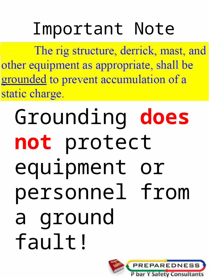
Important Note
Grounding does not protect equipment or personnel from a ground fault!

Do it right

Canadian Electrical Code and Standards on Rigs
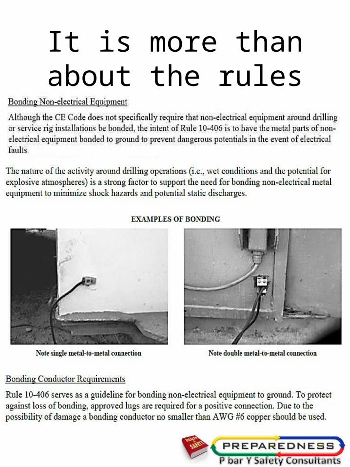
It is more than about the rules

17
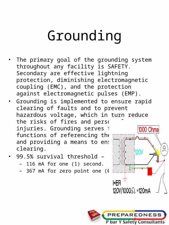
Grounding• The primary goal of the grounding system throughout any
facility is SAFETY. Secondary are effective lightning protection, diminishing electromagnetic coupling (EMC), and the protection against electromagnetic pulses (EMP).
• Grounding is implemented to ensure rapid clearing of faults and to prevent hazardous voltage, which in turn reduce the risks of fires and personnel injuries. Grounding serves the primary functions of referencing the AC systems and providing a means to ensure fault clearing.
• 99.5% survival threshold – – 116 mA for one (1) second.– 367 mA for zero point one (0.1) second.
18
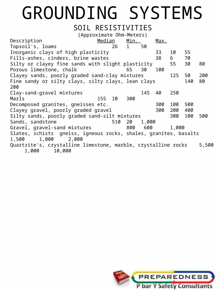
GROUNDING SYSTEMSSOIL RESISTIVITIES(Approximate Ohm-Meters)
Description Median Min. Max.Topsoil's, loams 26 1 50Inorganic clays of high plasticity 33 10 55Fills-ashes, cinders, brine wastes 38 6 70Silty or clayey fine sands with slight plasticity 55 30 80Porous limestone, chalk 65 30 100Clayey sands, poorly graded sand-clay mixtures 125 50 200Fine sandy or silty clays, silty clays, lean clays 140 80 200Clay-sand-gravel mixtures 145 40 250Marls 155 10 300Decomposed granites, gneisses etc. 300 100 500Clayey gravel, poorly graded gravel 300 200 400Silty sands, poorly graded sand-silt mixtures 300 100 500Sands, sandstone 510 20 1,000Gravel, gravel-sand mixtures 800 600 1,000Slates, schists gneiss, igneous rocks, shales, granites, basalts 1,500 1,000 2,000Quartzite's, crystalline limestone, marble, crystalline rocks 5,500 1,000 10,000
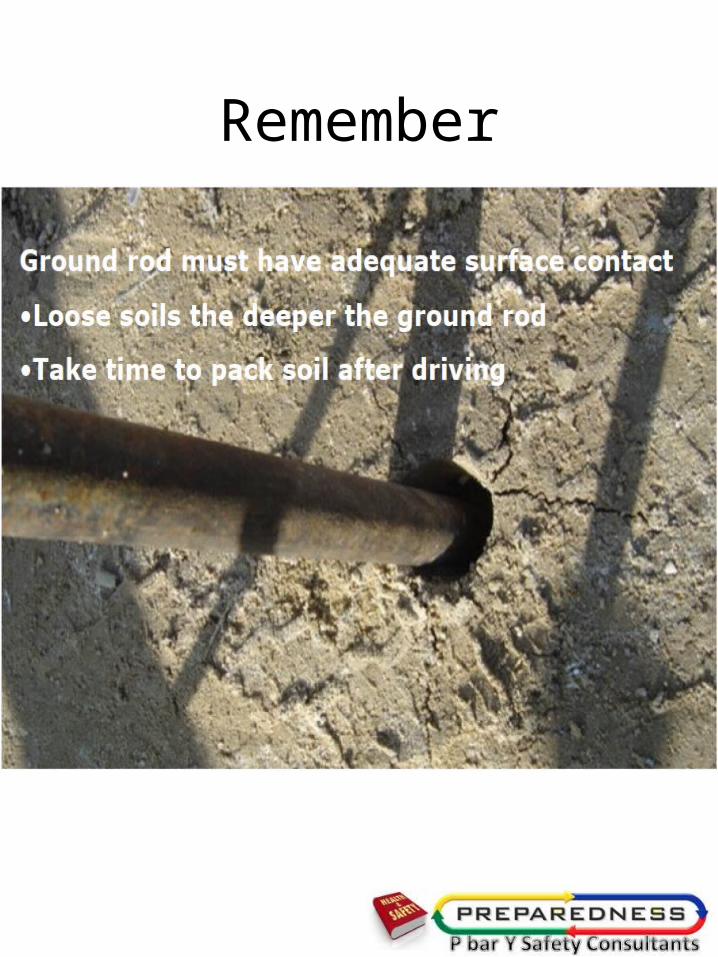
Remember

Did you test that connection.

Grounding of gang-operated switch handle

On top of a trip hazard it’s not grounded properly
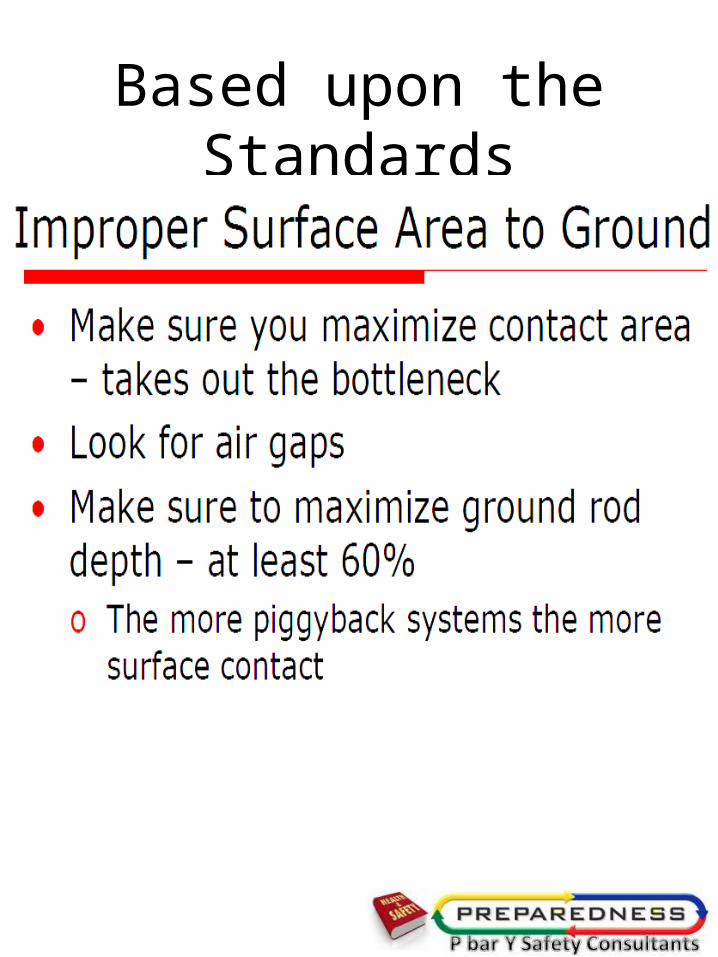
Based upon the Standards

The Bonding Connection
• Every piece of conductive metal which is a part of our system or likely to become energized …
• Must be connected together by an electrically continuous metal-to-metal contact or by an equipment grounding conductor
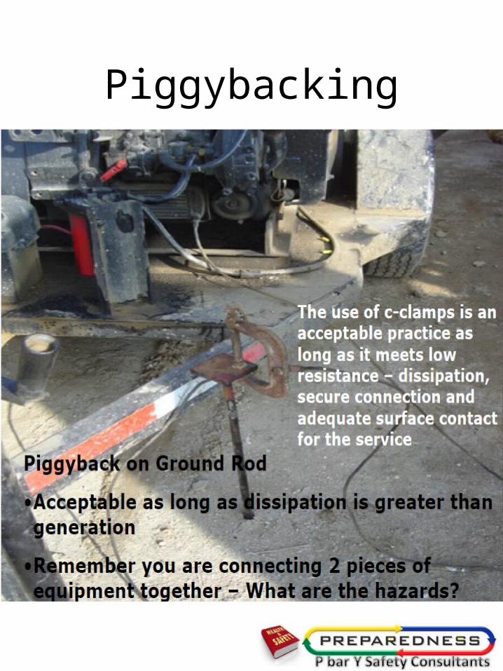
Piggybacking

In Review …
• Grounding is a connection to earth intended to protect our electrical system from lightning and high voltage
In Review …
• The overcurrent device protects our electrical system from overload and short circuit

In Review …
• The overcurrent device protects our electrical system from a ground fault condition if …..

In Review …
• Proper bonding …
• Has created a permanent, electrically continuous and low impedance path
• Which allows fault current to return to the neutral at the service
Wiring Methods Are Critical
• A wiring method that has been specifically designed as an equipment grounding conductor, and
• Engineered to assure a low impedance fault current path, is
• Clearly the best choice for a safe electrical installation

The Electrical Code is backed up by the API

How are you checking

Questions?