boiler controller - harsco industrial patterson-kelley: hot...
TRANSCRIPT
© 2011 Harsco Industrial, Patterson-Kelley Printed: 12/10/2012
ENVI® Boiler Controller
Advanced User’s Guide
Installation Date: _______________________
Harsco Industrial, Patterson-Kelley 100 Burson Street East Stroudsburg, PA 18301 Telephone: (877) 728-5351 Facsimile: (570) 476-7247 www.harscopk.com
ENVI® Control Rev. 2.1 (11/18/2011)

ENVI® Control
2
1.0 ENVI® BOILER CONTROL .................................................................................. 3
1.1 Operation of the ENVI® Control ............................................................................................ 4 1.2 Menu Screen ......................................................................................................................... 5 1.3 Boiler Status Screen ............................................................................................................. 5 1.4 Information Menu .................................................................................................................. 6 1.5 Errors Menu .......................................................................................................................... 8 1.6 Program Parameters Menu................................................................................................... 8
1.6.1Initial Setup of the Control .................................................................................................... 8 1.6.2 CH Settings ................................................................................................................... 9 1.6.3 CH Modes ................................................................................................................... 11 1.6.4 DHW Settings ............................................................................................................. 14 1.6.5 Boiler settings……………………………………………….……………………………15
1.7 Configuration Menu: ............................................................................................................ 16 1.8 Cascade Menu: .................................................................................................................. 16
1.8.1 Control Mode .............................................................................................................. 17 1.8.2 Master Settings ........................................................................................................... 17 1.8.3 Master Modes ............................................................................................................. 18 1.8.4 Cascade Settings ........................................................................................................ 20
1.9 Service Menu: ..................................................................................................................... 21
2.0 TROUBLESHOOTING ....................................................................................... 23
2.1 Troubleshooting Table ........................................................................................................ 23 2.1.1 The Loss of Power ...................................................................................................... 24 2.1.2 Flame Errors ............................................................................................................... 24
2.2 Manual Reset Error Codes – A## ....................................................................................... 25 2.3 Auto-reset Error Codes – E## ............................................................................................ 26
3.0 APPENDIX – BOILER DEFAULT SETTINGS.................................................... 27
3.1 MACH® Boiler Parameters .................................................................................................. 27 3.2 Modu-Fire® Forced Draft Boiler Parameters ....................................................................... 28
3.3 Parameter worksheet……………………………………………………………………..30
4.0 APPENDIX - MODBUS® INTERFACE ............................................................... 32
4.1.1 Descriptions of MODBUS® Register Map ................................................................... 33 4.1.2 Boiler State ................................................................................................................. 34 4.1.3 Information Byte .......................................................................................................... 34 4.1.4 Sequence Byte ........................................................................................................... 34
5.0 MODBUS CONFIGURATION……………………………………………..………….35

ENVI® Control
3
1.0 ENVI® BOILER CONTROL
The ENVI® boiler control consists of 3 components and is an intelligent control system with advanced features such as text-based display, MODBUS communication capabilities, and boiler sequencing. Fire rate and setpoint can be controlled via. 0-10VDC. Errors are date and time stamped, and the control records burner high, low and mid run hours. One control for temperature control, flame safeguard, firing rate control, blocked flue protection, outdoor air reset, freeze protection, built-in cascade sequencing and more.
ENVI APPLICATION Note: The ENVI control is capable of running the boiler on its own. However, certain applications warrant the purchase and installation of separate sensors such as:
26-0000-0507 Sensor, outdoor air, Tasseron BP-0000-0279 Sensor, header sensor kit, for DHW (ENVI® Control) 23-0000-0539 Sensor, strap on, ENVI® Control, 12K
These sensors will allow the ENVI control to sense the locations needed to perform properly. The ENVI control is also capable of accepting building management control via. 0-10VDC, MODBUS and other languages with the use of the XPC Protocol converter which is also installed and sold separately.
The user should become thoroughly familiar with the operation of the boiler and controls before attempting to make any adjustments.
The ENVI® control consists of three components: the main board, the interface board and a text-based display panel. The display panel is used to setup and monitor boiler operation by means of six push buttons; MENU, BACK, ENTER, UP, DOWN, and RESET as shown below. There are shortcut functions also associated with these buttons; LIGHT, SET PT, DHW, SVC and CANCEL. The four line screen shows boiler operating information on various screens. The display screen is backlit for ease of viewing. Press the BACK button to illuminate the backlight.
ENVI® Control
4
1.1 OPERATION OF THE ENVI® CONTROL
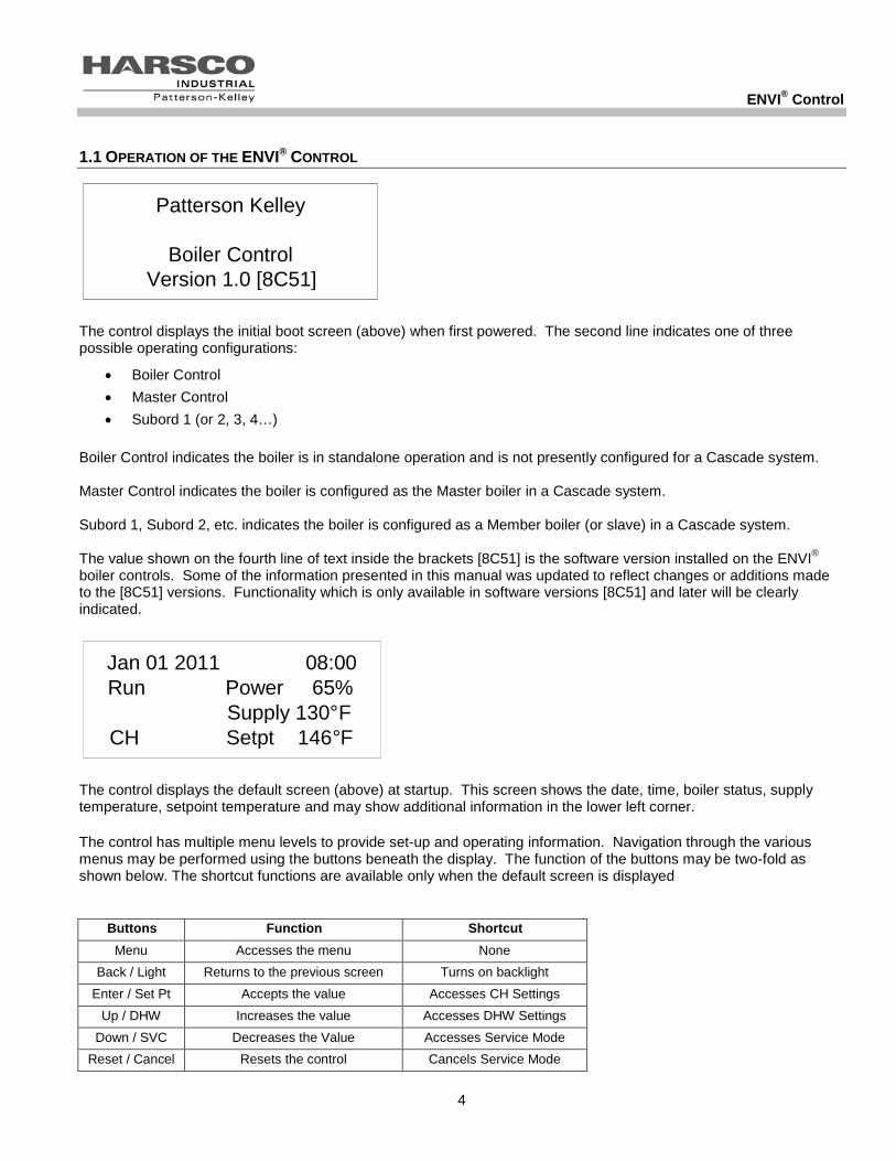
The control displays the initial boot screen (above) when first powered. The second line indicates one of three possible operating configurations:
• Boiler Control • Master Control • Subord 1 (or 2, 3, 4…)
Boiler Control indicates the boiler is in standalone operation and is not presently configured for a Cascade system. Master Control indicates the boiler is configured as the Master boiler in a Cascade system. Subord 1, Subord 2, etc. indicates the boiler is configured as a Member boiler (or slave) in a Cascade system. The value shown on the fourth line of text inside the brackets [8C51] is the software version installed on the ENVI® boiler controls. Some of the information presented in this manual was updated to reflect changes or additions made to the [8C51] versions. Functionality which is only available in software versions [8C51] and later will be clearly indicated.
The control displays the default screen (above) at startup. This screen shows the date, time, boiler status, supply temperature, setpoint temperature and may show additional information in the lower left corner. The control has multiple menu levels to provide set-up and operating information. Navigation through the various menus may be performed using the buttons beneath the display. The function of the buttons may be two-fold as shown below. The shortcut functions are available only when the default screen is displayed
Buttons Function Shortcut Menu Accesses the menu None
Back / Light Returns to the previous screen Turns on backlight Enter / Set Pt Accepts the value Accesses CH Settings
Up / DHW Increases the value Accesses DHW Settings Down / SVC Decreases the Value Accesses Service Mode
Reset / Cancel Resets the control Cancels Service Mode
Menu Standby Information Errors
Patterson Kelley
Boiler Control Version 1.0 [8C51]
Mar 12 2009 08:00 Run Power 65%
Supply 130 ° F CH Setpt 146 ° F
Jan 01 2011 08:00 Run Power 65%
Supply 130 ° F CH Setpt 146 ° F

ENVI® Control
5
1.2 MENU SCREEN
Pressing the MENU button provides access to the following sub-menus:
• Standby • Information • Errors • Program Parameters • Configuration • Cascade Menu • Service
Use the UP and DOWN buttons to scroll to the desired menu and the ENTER button to select that menu. The menu is displayed in a list format. Use the DOWN button to scroll to the next item in the list.
1.3 BOILER STATUS SCREEN
Pressing ENTER at the STANDBY menu returns the boiler status (default) screen described in Section 1.1 above. Additionally, pressing BACK will achieve the same results. The default screen displays the current operating status. A list of possible operating statuses is shown below:
• Standby • Checking Air Switch • Pre Purge • Ignition • Run • Post Purge • Post Pumping • Reset • Blocking • Locking
Menu Standby Information Errors
Menu Standby Information Errors

ENVI® Control
6
1.4 INFORMATION MENU
Pressing ENTER at the INFORMATION menu displays the following information.
Use the UP and DOWN buttons to scroll through the INFORMATION menu.
Information Supply Temp 122 ° F Return Temp 119 ° F DHW Temp 14 ° F
Information Supply Temp 122 ° F Return Temp 119 ° F DHW Temp 14 ° F
Information Supply Temp 122 ° F Return Temp 119 ° F DHW Temp 14 ° F

ENVI® Control
7
Display Description Units Open/Shorted
Sensor Indication Supply Temp Outlet or supply Temperature °F 14°F / 244°F Return Temp Inlet or return Temperature °F 14°F / 244°F
DHW Temp Domestic Hot Water Temperature at the location of the sensor(field installed) °F 14°F / 244°F
Flue gas Temp Flue Gas Temperature °F 50°F / 280°F
HX Temp Heat Exchanger Temperature °F 14°F / 244°F Outside Temp
Outside Air Temperature at the location of the sensor (field installed) °F -40°F / 176°F
CH set Temp Comfort Heat Set Temperature °F N/A DHW set Temp Domestic Hot Water Set Temperature °F N/A
Header Temp Header Temperature at the location of the sensor(field installed) °F 244°F / 244°F
Flame signal Flame Signal(older versions yes/no) μA < 1.7 μA = Flame Not Detected > 1.7 μA = Flame Detected 0-10
Fan speed Fan Speed RPM 0-9999 Analog in Analog Input VDC Volts DC Analog out Analog Output N/A Not Currently Used Ignitions Number of Ignitions # 0-99999 Burn Hi HR Hours at High Fire (75% to 100%) HRS 0-99999 Burn MD HR Hours at Medium Fire (45% to 75%) HRS 0-99999 Burn LO HR Hours at Low Fire (20% to 45%) HRS 0-99999 Water press Water Pressure PSI Not Currently Used
Water level Water Level Sensor Status Off/On 0 = Low Water Cutoff 1 = Low Water Cutoff Detects Water
Low gas press Low Gas Pressure Sensor Status Off/On 0 = Low Gas Pressure Switch Open
1 = Low Gas Pressure Switch Closed
Air pressure Air Pressure Switch Status Off/On 0 = Air Pressure Switch Open 1 = Air Pressure Switch Closed
Blocked flue Blocked Flue Switch Status Off/On 0 = High Exhaust Back Pressure Switch Open 1 = High Exhaust Back Pressure Switch Closed
CH pump Comfort Heat Pump Status Off/On 0 = CH Pump Off 1 = CH Pump On
DHW pump Domestic Hot Water Pump Status Off/On 0 = DHW Pump Off 1 = DHW Pump On
Air damper Air Damper Status Off/On 0 = Air Damper Relay Off 1 = Air Damper Relay On
Hi gas pressure Hi Gas Pressure Switch Status Off/On 0 = Hi Gas Pressure Switch Open
1 = Hi Gas Pressure Switch Closed

ENVI® Control
8
1.5 ERRORS MENU
Apr 20 2009 14:20 Locking IGNITION FAILURE Err:A01
Apr 20 2009 14:20 Locking IGNITION FAILURE Err:A01
In the event of an error, the default screen displays the error message and code (above left). Pressing ENTER at the ERROR menu displays information about the most recent error (above right). Pressing UP and DOWN scrolls through several lines of information about the status of the boiler during the error.
The error information stored is shown below in the table.
Display Description Units Varies Error Description N/A Supply Temp Outlet Temperature °F Return Temp Inlet Temperature °F
DHW Temp Domestic Hot Water Temperature °F
Flue gas Temp Flue Gas Temperature °F HX Temp Heat Exchanger Temperature °F Outside Temp Outside Air Temperature °F Operation Mode Boiler Operation Mode (CH/DHW) °F Days run Accumulated Days Runtime # Varies Boiler Status Error code Error Code N/A Date Date Error Occurred DD-MM-YY Time Time Error Occurred 24:00
1.6 PROGRAM PARAMETERS MENU
1.6.1 Initial Setup of the Control
Press the MENU button, scroll down with the DOWN button and select PROGRAM PARAMETERS from the menu by pushing ENTER. A screen opens that allows the user to view and change various operating parameters. There are three access levels including User, Service Level 1 and Service Level 2. OEM settings can be viewed, but cannot be changed in the field. Service Level 1 and Service Level 2 require access codes. Access codes are provided to those individuals who have been properly trained by Harsco Industrial, Patterson-Kelley.
ErrorsIGNITION FAILURE Supply Temp 122°FReturn Temp 119°F
ErrorsIGNITION FAILURE Supply Temp 122°FReturn Temp 119°F
ErrorsIGNITION FAILURE Supply Temp 122°FReturn Temp 119°F

ENVI® Control
9
Boiler Settings:
Operates the boiler.
Overrides CH and DHW values when needed for safety purposes.
CH Settings:
Works outside of boiler setting to create a more efficient design of operation.
Also contains the different modes of operations available.
Also holds the outdoor air curve settings.
DHW Settings
Works along with CH setting for the operation of the domestic hot water application.
OEM Settings
These setting are non configurable.
Four menus (or parameters) are available:
Menu Description
• CH settings Comfort Heat Settings
• DHW settings Domestic Hot Water Settings
• Boiler Settings Boiler Operating Settings
• OEM Settings Original Equipment Manufacturer Settings
To select a parameter, position the arrow next to the desired parameter and press ENTER. Use the UP and DOWN buttons to change the parameter values. Press the ENTER button to save the new value.
CAUTION: Do not change any parameter unless specified or absolutely needed. Changing of the parameters may cause the boiler to operate improperly or not at all.
1.6.2 CH Settings
ParametersCH settings DHW settings Boiler settings
ParametersCH settings DHW settings Boiler settings
From the PROGRAM PARAMETERS menu, press ENTER at the CH SETTINGS menu to access the comfort heat parameters listed in the table below. Alternatively, pressing ENTER at the STANDBY menu also accesses the CH SETTINGS menu.

ENVI® Control
10
Comfort Heat CH Parameters
ENVI® Text Display Function
Range Units Passcode
Level CH Setpoint Comfort Heat Setpoint See Appendix I °F User BLR OP (Boiler Operation) Boiler / Pump Run settings 0-3 User
Off = 0, On = 1, Off/Pump On = 2, and On/Pump On = 3
0 = Boiler Off, Pump Off 1 = Boiler On, Pump Off 2 = Boiler Off, Pump On 3 = Boiler On, Pump On
CH Mode Comfort Heat Operation Mode 0-8 SVC1 CH Mode 0 (Setpoint & Stat) See 1.6.3.1 below 0 CH Mode 1 (Outdoor &Stat) See 1.6.3.2 below 1 CH Mode 2 (Outdoor Control) See 1.6.3.3 below 2 CH Mode 3 (Setpoint Control) See 1.6.3.4 below 3 CH Mode 4 (Header & Stat) See 1.6.3.5 below 4 CH Mode 5 (Header & Outdoor & Stat) See 1.6.3.6 below 5 CH Mode 6 (Header & Outdoor) See 1.6.3.7 below 6 CH Mode 7 (Analog Setpoint) See 1.6.3.8 below 7 CH Mode 8 (Analog Firing Rate) See 1.6.3.9 below 8
Hi ODA Temp Maximum Outdoor Air Temperature 40 – 86 °F SVC1 Min ODA SetP Minimum Boiler W.T. Setpoint See Appendix I °F SVC1 Lo ODA Temp Minimum Outdoor Air Temperature -18 – 59 °F SVC1 Max ODA SetP Maximum Boiler W.T. Setpoint See Appendix I °F SVC1 ODA Shutdown Outdoor Air Shutdown Temperature 45 – 140 °F SVC1 Night Setback Reduces Boiler Setpoint When Enabled 0 – 58 °F SVC1
Hysteresis On On Differential (shoots start up of the boiler below setpoint) 0 – 22
°F SVC1
Hysteresis Off Off Differential (shoots temperature above setpoint) 0 – 22
°F SVC1
CH Post Pump time Pump Time After Burner Shuts Off 0 – 2550 Sec SVC1
Anti-Cyc Time Restart Time Delay to Prevent Short Cycling 0 – 2550
Sec SVC2
Prop Band Proportional Band 0 – 230 °F SVC2 Integral Rate Integral Rate 0 – 255 Sec SVC2 Der Time Derivative Time 0 – 255 Sec SVC2
PMP on demand Switches pump contacts to energize upon call for heat Yes/no
SVC2
W.T.= water temperature.

ENVI® Control
11
1.6.3 CH Modes
There are nine CH Modes (0-8). A more detailed description of each mode is included below.
1.6.3.1 CH Mode = 0 (Setpoint & Stat)
Setpoint is the desired outlet water temperature. In this mode, an external thermostat or other control (stat) controls the heat demand (or enable/disable). Upon heat demand (or enable/disable), the ENVI® control fires and modulates the boiler to maintain outlet water temperature at the setpoint. The upper (HYSTERESIS OFF) and lower (HYSTERESIS ON) temperature differentials control the temperature at which the burner turns on or off.
HYSTERESIS=DIFFERENTIAL
Example: A boiler with the following parameters (SETPOINT = 160 °F, HYSTERESIS OFF = 9 °F, HYSTERESIS ON = 10 °F) modulates to try to maintain 160° F. If the temperature increases above 169° F (160 °F SETPOINT + 9°F HYSTERESIS OFF), the boiler will shut off. Once it shuts off, it will not restart until the temperature drops below 150° F (160 °F SETPOINT – 10°F HYSTERESIS ON). This is illustrated graphically below.
The MIN SETPOINT and MAX SETPOINT parameters limit the setpoint range. See Appendix 3.1 and 3.2 for the default values.
1.6.3.2 CH Mode = 1 (ODA & Stat)
In this mode, setpoint is varied by the outdoor air temperature (ODA). An external thermostat or other control (Stat) controls the heat demand (or enable/disable), upon heat demand (or enable/disable), the ENVI® control fires and modulates the boiler to maintain outlet water temperature at the setpoint. The upper (HYSTERESIS OFF) and lower (HYSTERESIS ON) temperature differentials control the temperature at which the burner turns on or off.
HYSTERESIS=DIFFERENTIAL
The boiler maximum outdoor air setpoint (MAX ODA SETP) is the water temperature setting at or below the (LOW ODA TEMP). The boiler minimum setpoint (MIN ODA SETP) occurs when the outdoor air is at or above the maximum outdoor temperature (HI ODA TEMP). The boiler set points for “in between“ values of outdoor air temperature follow the line connecting the two end points of the outdoor air reset graph (see example below).
0 10 20 30 40 50 60 70 80
Outdoor Air Temperature (°F)
Boi
ler S
etpo
int (
°F)
190180170160150140 130 120 110 100 90 80 7060
Max ODA Setpoint
Min ODA Setpoint
Low
OD
A T
emp
Hi O
DA
Tem
p
0 10 20 30 40 50 60 70 80
Outdoor Air Temperature (°F)
Boi
ler S
etpo
int (
°F)
190180170160150140 130 120 110 100 90 80 7060
Max ODA Setpoint
Min ODA Setpoint
Low
OD
A T
emp
Hi O
DA
Tem
p
Internal Setpoint
145
150
155
160
165
170
175
0 10 20 30 40
Time
Boiler Temperature
Boiler Set Point
Boiler Turns On
Boiler Turns Off

ENVI® Control
12
Example: Using the values in the table shown below, the boiler setpoint is 80° F when the outdoor air temperature is 70° F. As the outdoor air temperature drops, the boiler setpoint increases until the outdoor air temperature is 0° F. At this point the boiler reaches its maximum setpoint of 180° F. If the outdoor air temperature drops further, the boiler setpoint remains at 180° F. Settings for example shown at left: 1.6.3.3 CH Mode = 2 (Outdoor Control)
In this mode, setpoint is varied by the outdoor air temperature (ODA). The heat demand is generated when the temperature of the outdoor sensor drops below the ODA SHUTDOWN. Upon heat demand, the ENVI® control fires and modulates the boiler to maintain outlet water temperature at the setpoint. The upper (HYSTERESIS OFF) and lower (HYSTERESIS ON) temperature differentials control the temperature at which the burner turns on or off. In this mode, the enable/disable terminals (Stat) operate the night setback function. See the wiring diagram on your boiler.
ENVI® Text Display Function Range Units Pass code Level
Hi ODA Temp Outdoor air Maximum Design Temperature 40 - 86 °F SVC1 Min ODA SetP (Setpoint Min) Minimum Boiler water Setpoint 45 - 176 °F SVC1 Lo ODA Temp (Outdoor Min) Outdoor air Minimum Design Temperature -18 - 59 °F SVC1 Max ODA Setp (Setpoint Max) Maximum Boiler water Setpoint 68 - 185 °F SVC1 ODA Shutdown Outdoor Air Shutdown Temperature 45 - 140 °F SVC1 Night Setback Reduces Boiler Setpoint When Enabled 0 - 58 °F SVC1 Hysteresis On On Differential (below setpoint) 0 - 22 °F SVC1 Hysteresis Off Off Differential (above setpoint) 0 - 22 °F SVC1 Post pump tme Pump run time after boiler disabled 0-2550 Seconds SVC1 Anti cyc tme Anticycle timer will hold between cycles 0-2550 seconds SVC2 Prop band Proportional band 0-230 F SVC2 Integral RTE Integral rate 0-255 Seconds SVC2 DER time Derivative time 0-255 seconds SVC2
PMP on demand Allows the boiler pump to run upon a call for heat Yes/no
SVC2
HYSTERESIS=DIFFERENTIAL
1.6.3.4 CH Mode = 3 (Setpoint Control)
In this mode, the boiler functions as described in 1.6.3.1, CH Mode = 0 except that the external thermostat does not create the call for heat. Closure of the stat terminals causes the night setpoint to engage.
CH Mode 1
Hi ODA Temp (Outdoor TMax) 70 °F Min ODA SetP (Setpoint TMin) 80 °F Low ODA Temp (Outdoor TMin) 0 °F Max ODA Setp (Setpoint TMax) 180 °F Hysteresis On (On Differential) 10 °F
Hysteresis Off (Off Differential) 9 °F

ENVI® Control
13
80Min ODA Setpoint
170Max ODA Setpoint
0 1 2 3 4 5 6 7 8 9 10
Analog Input (VDC)
Boi
ler S
etpo
int (
°F)
190180170160150140 130 120 110 100 90 80 7060
Max ODA Setpoint
Min ODA Setpoint
1.5V
80Min ODA Setpoint
170Max ODA Setpoint
0 1 2 3 4 5 6 7 8 9 10
Analog Input (VDC)
Boi
ler S
etpo
int (
°F)
190180170160150140 130 120 110 100 90 80 7060
Max ODA Setpoint
Min ODA Setpoint
1.5VNOTICE! When in analog control mode, enable/disable terminals are non-functional.
1.6.3.5 CH Mode = 4 = (Header & Stat)
In this mode, the boiler functions as described in 1.6.3.1, CH Mode = 0 except that the boiler maintains the setpoint temperature in the header piping. The external thermostat creates the call for heat.
1.6.3.6 CH Mode = 5 = (Header & ODA & Stat)
This mode is a combination of CH Mode 1 (ODA & Stat) and CH Mode 4 (Header & Stat). The setpoint temperature is maintained in the header piping based on a reset schedule that is determined from an outdoor air sensor. An external thermostat controls the heat demand.
1.6.3.7 CH Mode = 6 = (Header & Outdoor)
This mode is a combination of CH Mode 2 (Outdoor Control) and CH Mode 4 (Header & Stat). The temperature is maintained in the header piping based on a reset schedule that is determined from an outdoor air sensor. The call for heat is generated by the temperature of the outdoor sensor dropping below the ODA SHUTDOWN. The enable/disable terminals (Stat) operate the night setback function. See the wiring diagram on your boiler.
1.6.3.8 CH Mode = 7 = (Analog Control of Setpoint)
In this mode, an external 0-10 VDC signal controls the setpoint of the boiler. Applying a voltage of at least .5 VDC creates the heat request. Applying 2 VDC sets the boiler setpoint to MIN ODA SETPOINT. Applying 10 VDC sets the boiler setpoint to MAX ODA SETPOINT. Applying less than .5 VDC removes the heat request.
1.6.3.9 CH Mode = 8 = (Analog Control of Firing Rate)
In this mode, an external 0-10 VDC signal controls the firing rate of the boiler. A signal of .5 VDC generates a heat request and is required to start the boiler. At 2 VDC the firing rate is 20% and at 10 VDC the firing rate is 100%. A signal below .5 VDC removes the heat request.
0 1 2 3 4 5 6 7 8 9 10
Analog Input (VDC)
Firin
g R
ate
(%)
100
90
80
70
60
50
40
30
20
10
0
1.5V
0 1 2 3 4 5 6 7 8 9 10
Analog Input (VDC)
Firin
g R
ate
(%)
100
90
80
70
60
50
40
30
20
10
0
1.5V
NOTICE! When in analog control mode, enable/disable terminals are non-functional.

ENVI® Control
14
1.6.4 DHW Settings
ParametersCH settings DHW settings Boiler settings
ParametersCH settings DHW settings Boiler settings
From the PROGRAM PARAMETERS menu, press ENTER at the DHW SETTINGS menu to access the domestic hot water parameters listed in the table below. Alternatively, pressing UP at the STANDBY menu also accesses the DHW SETTINGS menu.
1.6.4 Domestic Hot Water (DHW) Parameters
ENVI® Text Display Function Range Units Passcode Level
DHW mode None = 0 Storage & Sensor = 1 Storage & Stat = 2 Plate Heat Exch = 3
Type of System 0 = No Domestic Hot Water 1 = Storage Tank with Temperature Sensor 2 = Storage Tank with Thermostat 3 = Plate Heat Exchanger w/Flow Switch
0 – 3 SVC1
DHW Type CH/DHW = 0 DHW Priority = 1 3 Way Valve NC = 2
Domestic Hot Water Operation Type 0 = Simultaneous CH and DHW Pumps 1 = DHW pump has priority over CH pump 2 = 1 Boiler Pump: when 3 way valve Normally Closed = DHW when 3 way valve Powered Open = CH
0 – 2 SVC1
DHW setpoint Setpoint for Domestic Hot Water Output 86 – 185 °F User Tank set Setpoint of Storage Tank 104 – 162 °F User ON different Boiler On Differential 0 – 36 °F SVC1 OFF different Boiler Off Differential 0 – 36 °F SVC1 Tank off dif Tank Off Differential 0 – 36 °F SVC1 Tank on diff Tank On Differential 0 – 36 °F SVC1 Post pmp Time DHW Post Pump Time 0 – 255 Sec SVC1 Prop band Proportional Band 0 – 230 °F SVC2 Integral RTE Integral Rate 0 – 255 Sec SVC2 DER time Derivative Time 0 – 255 Sec SVC2 PMP on demand* DHW Pump On Demand No / Yes SVC2 Priority Time* 0 – 255 Min SVC1
The DHW system designs that can be accommodated by this control include a storage tank with temperature sensor (Type 1), a storage tank with thermostat (Type 2), and a plate heat exchanger (Type 3).

ENVI® Control
15
1.6.4.1 Storage Tank with Temperature Sensor (Storage & Sensor 1)
A storage tank equipped with a temperature sensor is connected to the boiler. When the temperature sensor reads that the tank temperature is below the TANK SET parameter by the TANK ON DIFF, the DWH pump circuit is energized and the boiler starts and supplies heat to the tank. The boiler modulates the firing rate to maintain the DHW SETPOINT at the boiler outlet. When the temperature in the tank exceeds the TANK SET parameter by the TANK OFF DIFF, the boiler shuts off the burner and post pumps for a pre-set time (POST PMP TIME). 1.6.4.2 Storage Tank with Thermostat (Storage & Stat 2)
A storage tank equipped with a thermostat is connected to the boiler. When the thermostat closes, the DWH pump circuit is energized and the boiler starts and supplies heat to the tank. The boiler modulates the firing rate to maintain the DHW SETPOINT at the boiler outlet. When the temperature in the tank exceeds the thermostat setting, the thermostat opens and the boiler shuts off the burner and post pumps for a pre-set time (POST PMP TIME).
1.6.4.3Heat Exchanger without Storage (Plate Heat Exchanger 3)
A plate heat exchanger equipped with a DHW flow proving device and a temperature sensor is connected to the boiler. When the flow proving device closes, it creates a call for heat and the boiler pump starts. If the DHW water temperature is below the DHW SETPOINT by the ON DIFFERENTIAL, the boiler fires and supplies heat to the exchanger. The boiler modulates the firing rate to maintain the DHW SETPOINT at the boiler outlet. When the temperature of the boiler water rises above the DHW SETPOINT by the OFF DIFFERENTIAL, the boiler shuts off the burner and post pumps for a pre-set time (POST PMP TIME). When the demand is satisfied, the flow proving device breaks the call for heat.
1.6.5 Boiler Settings
The BOILER SETTINGS are password protected by a numerical code and should only be changed by a factory authorized service representative. These settings are:
Boiler type- this is the factory setting for the boiler Max fan speed- this is the boilers maximum fan speed Min fan speed- this is the boilers minimum fan speed Max setpoint- this is the boilers max set point Min setpoint- this is the boilers minimum set point Max temp- this is the boilers maximum temperature Mod back dif- this controls the difference in temp between the supply and return at which the boiler is driven to low fire for safety considerations. Lo fire hold- this setting is in seconds and holds the boiler in low fire prior to modulation upon start up. Post purge- this setting is in seconds and holds the fan on after the firing sequence is completed to remove any excess gases within the combustion chamber. Accel BNR ON- this adjusts the burner’s ramp speed upon power increase rate. Accel BNR OFF- this adjusts the burner’s ramp speed upon power decrease rate. FP enable- this sets frost protection set high, low or off Pwr lmt step- this value (lower slower) adjusts the fire rate and time at which the boiler steps from one fire rate to the next while modulating to load.
The OEM Settings are password protected by a numerical code and should only be changed by Harsco Industrial, Patterson-Kelley personnel.

ENVI® Control
16
1.7 CONFIGURATION MENU:
The CONFIGURATION menu is a general menu that allows selection of the display language, date/time, code, °F/°C temperature selection and MODBUS® address.
LANGUAGE configuration allows the user to select English (default), French (future) or Spanish (future). DATE TIME is factory set. But, will need to be changed for different time zones, daylight savings time, ECT. CODE configuration indicates the display panel software version. ° F or ° C configuration allows the user to select Fahrenheit or Celsius. MODBUS® ADDRESS configuration allows the user to set the MODBUS® device identification.
1.8 CASCADE MENU:
With the power off, you can connect up to 24 boilers into the ENVI® Link network. Wires are connected from the Cascade terminals (A & B) on the master boiler to the Cascade terminals (A & B) on the member (or slave) boilers.
Connect A to A and B to B. The boilers are connected in series (daisy chain).
After making the boiler to boiler connections, select one boiler as the master boiler. Remove the auxiliary board cover (if present) and set the master/member selector switch to the MASTER position. Ensure that the remaining member boiler switches are set to the MEMBER position. A picture of the master/member selector switch is shown to the left. Note: the MASTER position is away from the blue transformer, while the MEMBER position is towards the blue transformer. The orientation of the board may vary from the picture shown.
CAUTION! Setting more than one master/member selector switch to the MASTER position may damage the control.
Turn the power on. Pressing ENTER at the CASCADE MENU allows the user to set the cascade features of the ENVI® boiler control. These settings include: CONTROL MODE, MASTER SETTINGS, CASCADE SETTINGS, INFORMATION ERRORS.
Cascade MenuControl Mode SAMaster Settings Cascade Settings
Cascade MenuControl Mode SAMaster Settings Cascade Settings
Cascade MenuControl Mode SAMaster Settings Cascade Settings
MenuErrors Program Parameters Configuration
MenuErrors Program Parameters Configuration
Member ------------
Master Switch

ENVI® Control
17
1.8.1 Control Mode
In this mode, the operational mode is selected (single boiler, master boiler, member boiler). When the mode is set as master, the unique address is automatically set to 0. When the mode is set as member(slave), the user enters a unique address (1-23) for each boiler.
1.8.2 Master Settings
The master settings are used in conjunction with the cascade settings to set the system response parameters. These settings are described in more detail after the list of settings.
ENVI® Text Display Function Range Units Pass code Level
HDR Setpoint Sets the operating
temperature at the header 104 – 194
°F SVC2
Power Mode 0 – 1 SVC2 Power Mode Min Boilers On
See Below 1.8.3.1 0
Power Mode Max Boilers On
See Below 1.8.3.2 1
Header Mode 0 – 4 SVC2 Header Mode (Header & Stat)
See Below 1.8.3.3 0
Header Mode (Header ODA & Stat)
See Below 1.8.3.4
1
Header Mode (Header & ODA)
See Below 1.8.3.5 2
Header Mode (HDR Setpt Control)
See Below 1.8.3.6 3
Header Mode (HDR Analog Setpt)
See Below 1.8.3.7 4
Hyst Start Blr See 1.8.3.8 below 0 – 36 °F SVC2 Hyst Stop Blr See 1.8.3.8 below 0 – 36 °F SVC2 Wait Blr Sw on See 1.8.3.8 below 1 – 255 Sec SVC2 Wait Blr sw off See 1.8.3.8 below 1 – 255 Sec SVC2
Prop Band (Proportional Band) Proportional Band 0 – 230
°F SVC2
Integral Rate Integral Rate 0 – 255 Sec SVC2 Der Time (Derivative) Derivative Time 0 – 255 Sec SVC2 Cyc Lmt Incrmnt See 1.8.3.8 below 0 – 50 Min SVC2 Cycl Limit Max See 1.8.3.8 below 1 – 255 Min SVC2 Hys Quic Start See 1.8.3.8 below 0 – 51 °F SVC2

ENVI® Control
18
ENVI® Text Display Function Range Units Pass code Level
Quic Start Tme See 1.8.3.8 below 1 – 255 Sec SVC2 Hys Quick Stop See 1.8.3.8 below 0 – 51 °F SVC2 Quic Stop Time See 1.8.3.8 below 1 – 255 Sec SVC2 LoLoad Waiting See 1.8.3.8 below 0 – 255 Sec SVC2 Start Rotation See 1.8.3.8 below 1 – 255 Hr SVC2 No Blr on Wait See 1.8.3.8 below 1 – 255 Min SVC2 Anti wind up See 1.8.3.8 below On/off SVC2
1.8.3 Master Modes
The master modes listed in the table above represent several control strategies for the Master/Member boiler network. These modes are described on the next page.
1.8.3.1 Power mode = 0, Min Boilers on (Not Recommended)
In this mode, two boilers run at high fire while the remaining boilers modulate. This satisfies the load with the minimum amount of boilers firing.
1.8.3.2 Power mode = 1, Max Boilers On (Parallel Modulation – Default Setting)
In this mode, the boilers modulate in parallel based on a signal from the master boiler. This satisfies the load with the necessary number of boilers firing at the lowest rate possible
1.8.3.3 Header Mode = 0, (Header & Stat)
In this mode, the master boiler controls the operation of all the boilers in the network to maintain a supply temperature at a common header. The heat demand is controlled by an external thermostat or other control (Stat). Upon heat demand, the ENVI® control on the Master boiler fires and modulates the boilers to maintain header water temperature at the header setpoint (cascade menu/Master settings). The upper (HYST STOP BLR) and lower (HYST START BLR) temperature differentials control the header temperature at which boilers are added or removed.
Example: The Master boiler operates the system to maintain the header setpoint of 160° F. If the temperature increases above 170° F (setpoint 160° F + 10°F HYST STOP BLR), a boiler will shut off. If the temperature decreases below 151°F (setpoint 160°F – 9°F HYST START BLR), another boiler will start.
1.8.3.4 Header Mode = 1, (Header ODA & Stat)
In this mode, the temperature is maintained in the header piping based on a reset schedule that is determined from an outdoor air sensor. The parameters for changing the reset schedule are in (Program parameters/CH Settings). The heat demand is controlled by an external thermostat wired to the enable/disable circuit.
1.8.3.5 Header Mode = 2, (Header & ODA)
In this mode, the temperature is maintained in the header piping based on a reset schedule that is determined from an outdoor air sensor. The parameters for changing the reset schedule are in (Program parameters/CH Settings). The call for heat is generated by the temperature of the outdoor sensor dropping below the ODA SHUTDOWN (Program parameters/CH settings). The enable/disable terminals (Stat) operate the night setback function. 1.8.3.6 Header Mode = 3, (Header Setpoint Control)
This mode is similar to Header Mode = 0, Header & Stat, described in 1.8.3.3, except there is no external thermostat. The heat demand is controlled by the header sensor. The enable/disable terminals operate the night setback function.

ENVI® Control
19
1.8.3.7 Header Mode = 4, (HDR Analog Setpoint)
In this mode, an external 0-10 VDC signal controls the setpoint of the Master boiler. Applying a voltage of at least
.5V creates the heat request. Applying 2 VDC sets the boiler setpoint to “Min ODA Setpoint”. Applying 10 VDC sets the boiler setpoint to “Max ODA Setpoint”. Applying less than0 .5 VDC removes the heat request.
1.8.3.8 Additional Master Settings
Hyst start blr (Differential Start Boiler) and
Hyst stop blr (Differential Stop Boiler)
are the temperature differentials below and above, respectively, the setpoint that the master boiler control uses to call other network boilers on/off.
Wait blr sw on and
Wait blr sw off (Wait Boiler Switching)
This parameter is the time the master boiler control waits to watch the effect of a change in the number of boilers operating, before making another change.
Cyc lmt inctmnt Cycl limit max Each time the starting or stopping of a boiler is detected a Cyc lmt incrmnt is added to the switch boiler counter. Every minute this counter is decreased with one (1). Only if the counter value is below Cycl limit max boilers can be switched on or off. This feature prevents the boilers from short cycling, leading to increased boiler lifespan.
Hys quic start
Quic start tme
Hys quick stop
Quic stop time
For those instances where the load changes rapidly quick start / quick stop parameters bypass the Wait blr sw on and Wait blr sw off parameters to allow the system to respond more quickly.
When the header temperature falls below the HDR SETPOINT by the HYS QUIC START temperature setting. The control uses the QUIC START TIME (a length of time) to stage on member boilers. The master control shortens the interval between boiler starts, allowing the system to catch up more quickly.
When the header temperature rises above HDR SETPOINT by the HYS QUIC STOP temperature setting temperature, the control uses the QUIC STOP TIME (time delay for quick start) to stop the member boilers. The master control shortens the interval between boiler stops, allowing the system to prevent overshooting the HDR SETPOINT.
Lo Load waiting
The LOLOAD WAITING is set on the master boiler control and used in conjunction with the various other low load settings found in the cascade menu. This parameter allows the master to turn on a boiler that is below the HDR
80Min ODA Setpoint
170Max ODA Setpoint
0 1 2 3 4 5 6 7 8 9 10
Analog Input (VDC)
Boi
ler S
etpo
int (
°F)
190180170160150140 130 120 110 100 90 80 7060
Max ODA Setpoint
Min ODA Setpoint
1.5V
80Min ODA Setpoint
170Max ODA Setpoint
0 1 2 3 4 5 6 7 8 9 10
Analog Input (VDC)
Boi
ler S
etpo
int (
°F)
190180170160150140 130 120 110 100 90 80 7060
Max ODA Setpoint
Min ODA Setpoint
1.5V
ENVI® Control
20
SETPOINT temperature if this time interval has passed. Additional low load settings are described in the Cascade Settings section of this manual.
Start rotation
The START ROTATION is a setting that the master control uses to determine the accumulated run time that each boiler is in the lead position of the sequence. The boiler designated as the master is included in the lead/lag sequence but the master control does not change.
No boiler on wait
The NO BLR ON WAIT is the time the ENVI® Control waits to override a hold from a cascade boiler. For example, a low return temperature hold for a non-condensing boiler in a hybrid system will trigger the NO BLR ON WAIT function. After the wait period expires, the ENVI® Control forces the non-condensing boiler to start.
Anti windup
When anti windup is on this prevents the lead or (Master) boiler from ramping to 100 percent fire rate before staging on the member (slave) boilers to satisfy the setpoint.
1.8.4 Cascade Settings
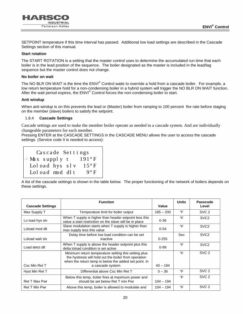
Cascade settings are used to make the member boiler operate as needed in a cascade system. And are individually changeable parameters for each member. Pressing ENTER at the CASCADE SETTINGS in the CASCADE MENU allows the user to access the cascade settings. (Service code II is needed to access):
A list of the cascade settings is shown in the table below. The proper functioning of the network of boilers depends on these settings.
Cascade Settings Function
Value Units Passcode
Level Max Supply T Temperature limit for boiler output 185 – 200 °F SVC 2
Lo load hys slv When T supply is higher than header setpoint less this value a start restriction on the slave will be in place 0-36
°F SVC2
Loload mod dlt Slave modulation starts when T supply is higher than max supply less this value 0-54
°F SVC2
Loload wait slv Delay time before low load condition can be set
inactive 0-255 Sec SVC2
Load detct dlt When T supply is above the header setpoint plus this delta loload condition is set active 0-99
°F SVC2
Csc Min Ret T
Minimum return temperature setting this setting plus the hystresis will hold out the boiler from operation
when the return temp is below the added set point. In a cascade system. 40 – 194
°F SVC 2
Hyst Min Ret T Differential above Csc Min Ret T 0 – 36 °F SVC 2
Ret T Max Pwr Below this temp, boiler fires at maximum power and
should be set below Ret T min Pwr 104 – 194 °F SVC 2
Ret T Min Pwr Above this temp, boiler is allowed to modulate and 104 – 194 °F SVC 2
Cascade SettingsMax supply t 191°FLoload hys slv 15°FLoload mod dlt 9°F
Cascade SettingsMax supply t 191°FLoload hys slv 15°FLoload mod dlt 9°F
Cascade SettingsMax supply t 191°FLoload hys slv 15°FLoload mod dlt 9°F

ENVI® Control
21
Cascade Settings Function
Value Units Passcode
Level inbetween min and max ret T power the boiler are
modulated on a linear curve.and should be set above Ret T Max Pwr
Prepump Period Time for prepump before boiler starts to ensure correct
return water temperature measurement 15 – 255 Sec SVC 2
No member boiler is allowed to start when the temperature of the header water is greater than the HDR SETPOINT or the boiler water is greater than the MAX SUPPLY T.
The member boilers are required to modulate back to a low firing rate when the temperature of the boiler is above the LoLoad Mod Dlt temp below the MAX SUPPLY T.
The modulation will be at a minimum when the condition (Max Supply T – LoLoad Mod Dlt + 8°F) is reached.
The members will also modulate back when the boiler water temp is within LoLoad Hys Slv of the HDR Setpoint.
Each member boiler can detect a low load condition when the member boiler water supply temp is greater than MAX SUPPLY T – LOLOAD HYS SLV or when the member boiler water supply temp is greater than HEADER SETPOINT – LOLOAD HYS SLV. Once a member detects a low load condition, it tells the master boiler and goes to minimum fire and waits for the LOLOAD WAIT SLV time period. The member boiler rechecks the low load condition at the end of this time and reports the status to the master. If the low load condition is still active, the master reduces the amount of active boilers and switches off the boiler with the low load condition. The Master boiler then waits for LOLOAD WAITING time period and re-evaluates the load situation. At the end of that time, if the low load condition is still detected by another member boiler, the master will shut down the member boiler. This process repeats in increments of one until no more boilers detect low load (or all the boilers are off).
Hybrid systems setup
In a hybrid system that contains both condensing and non-condensing boilers, cascade settings help prevent the non-condensing boilers from operating in a condensing mode. The CSC MIN RET T is the minimum return temperature setting. The factory default CSC MIN RET T setting for P-K THERMIFIC® and MODU-FIRE® FD boilers is 130°F. Each member boiler checks that the return water temperature is greater than the CSC MIN RET T plus the HYST MIN RET T. If the return temperature is too low, the non-condensing boiler signals the Master ENVI® control to skip this boiler. If a condensing boiler cannot be found, the Master ENVI® control goes into NO BLR ON WAIT. When the NO BLR ON WAIT time period expires, the first available boiler will start and burn at high fire until the boiler inlet temperature is greater than RET T MAX PWR. If the return water temperature remains below CSC MIN RET T, the NO BLR ON WAIT sequence repeats. When the return temperature exceeds RET T MIN PWR, the boilers release to modulate according to the master controller. Other boilers in the member network may be enabled and modulated to meet the load.
NOTICE! The Master ENVI® control will not override individual boiler protective parameters. For example, MOD BACK DIFF will still prevent the member boiler from exceeding the temperature differential setting.
1.9 SERVICE MENU:
This service menu allows the operator to manually set the boiler to HI or LOW operation for setup and/or troubleshooting. This menu is protected by the service level 1 code (SVC1). Pressing the SVC shortcut key (DOWN button when the default screen is present, see Section 1.1) accesses the SERVICE menu. Users can also access the

ENVI® Control
22
SERVICE menu by pressing the MENU button and using the UP and DOWN buttons until the cursor is next to SERVICE. Press ENTER. This menu is protected by the service level 1 code (SVC1).
NOTICE! Combustion adjustments should only be performed by service personnel experienced and knowledgeable on the operation of the Harsco Industrial, Patterson-Kelley boiler.
Two test modes are available:
1) BNR ON TEST HI LOW
2) BNR OFF FAN HI LOW
Press the up or down button to select BURNER ON TEST HI LOW or BURNER OFF FAN HI LOW, press ENTER. Then press up then enter to select HIGH or down then enter to select LOW operation.
The first test mode,
BNR ON TEST HI LOW, allows the service technician to hold the boiler in high or low fire during firing operation so that the combustion adjustment can be performed.
The second test mode,
BNR OFF FAN HI LOW, checks the fan rate with the burner off at high fan speed or at low fan speed.
These test modes will automatically terminate after 15 minutes of inactivity or can be terminated from the control/display panel by pressing the cancel/reset button Each boiler has a specific combustion adjustment procedure that is contained in each boilers specific Installation & Owners Manual. The correct combustion parameters are listed in the boiler specific manual as well. These specific procedures must be followed for the boiler being adjusted. There is a fire test from the factory on the back of the boiler.
ServiceBNR ON Test HI LOW BNR OFF Fan HI LOW
ServiceBNR ON Test HI LOW BNR OFF Fan HI LOW
ServiceBNR ON Test HI LOW BNR OFF Fan HI LOW

ENVI® Control
23
2.0 TROUBLESHOOTING
2.1 TROUBLESHOOTING TABLE
Symptoms: Possible Cause: Solution:
No Display, No Operation Loss of Power Restore Power. The control retains any error/lockout and may require a reset.
No Display, No Operation Fuse on Main Board is Blown
Replace fuse
Boiler runs with some operation compromised, such as no remote input, alarm output, flame detected output, cascade, MODBUS®, etc.
1) Fuse on Interface Board is Blown
2) Boilers were wired A to B during cascade set-up AND more than one master switch was set to MASTER.
1) Replace fuse on interface board.
2) Replace the interface board.
No Display, Boiler is Operating
1) Display is not wired properly
2) Light source is not functioning
3) S4 switch is in the off position
1) Check the display wires.
2) Use a flashlight to verify that text is present. Replace display board.
3) Turn on the S4 switch on the main board
Display continuously shows CONNECT INIT
Incorrect communication between control boards
Check communication wiring (twisted pair)
Verify that all three control boards (Main, Interface, and Display) have the same software version.
WARNING
If any boiler “Manual Reset” limit device trips, DO NOT
Reset the control without determining and correcting the cause.

ENVI® Control
24
2.1.1 The Loss of Power
In the event of a power failure (or when the On/Off switch is in the Off position), the display panel is not illuminated and the entire system is de-energized, closing all automatic valves and halting all boiler operations. When power is restored the sequence of operation will resume at Step 4. If any error/lockout is present when the power is lost, the control will retain that error/lockout and display the error/lockout when the power is restored. A manual reset may be required.
2.1.2 Flame Errors
FLAME_OUT_TOO_LATE_ERROR
FLAME_ERROR_1
FLAME_ERROR_2
These errors signify flame error. This may be caused by a failed or leaky gas valve or a flame detector malfunction. If gas valve leakage is suspected, the unit must be isolated by turning off the main gas supply line. Qualified and knowledgeable service personnel must be called to evaluate and repair/replace the failed parts.
The ENVI® boiler control will display text based error descriptions to indicate any problems with the boiler. There are two types of lockouts the control may experience: manual reset lockouts requiring an operator to press the reset button, and automatic reset lockouts that will self reset when the error condition clears. A comprehensive listing of the locking and blocking error codes is provided at the end of this section.

ENVI® Control
25
2.2 MANUAL RESET ERROR CODES – A##
A Code Error Int. nr Description A01 IGNIT ERROR 1 Three unsuccessful ignition attempts in a row
A02 TOO MANY FLAME FAILURES 24 Three times flame was lost during on demand
A03 T MAX LOCK ERROR 18 Overheat stat is open
A05 GV RELAY ERROR 5 Problems with gas valve relay= internal hardware error (pump not running)
A06 SAFTEY RELAY ERROR 6 Problems with gas valve relay = internal hardware error (pump not running)
A09 RAM ERROR 9 Internal software error
A09 FLAG BYTE INTEGRITY ERROR 27 Internal software error
A09 AD HI CPL ERROR 28 Internal software error
A09 AD LO CPL ERROR 29 Internal software error
A09 REGISTER ERROR 33 Internal software error
A10 E2PROM ERROR 12 No communication with E2prom
A12 WRONG EEPROM SIGNATURE 10 Contents of Eprom is not up-to-date
A13 STATE ERROR 13 Internal software error
A14 ROM ERROR 14 Internal software error
A15 15MS XRL ERROR 16 Internal software error
A16 20 MS XLR ERROR 22 Internal software error
A18 STACK ERROR 19 Internal software error
A19 FLAME OUT TOO LATE ERROR 20 Flame still present 10 sec. after closing the gas valve
A20 FLAME ERROR I 21 Flame detected just before gas valve opened
A30 HIGH GAS PRESSURE ERROR 32 Gas pressure is to high
A31 LOW GAS PRESSURE ERROR 31 Gas pressure is to low
A32 41MS ERROR 23 Internal software issue
A33 FAN ERROR 8 Fan deviation more than300 rpm longer than 1 minute (when fan speed > 4200 rpm this error is ignored)
A34 AIR PRESS SW NOT OPEN ERROR 25 Air pressure switch doesn’t open within 30 seconds
A35 AIR PRESS SW NOT CLOSED ERROR 26 Air pressure switch doesn’t close within 30 seconds
A37 UV SENSOR BROKEN 11 UV scanner not functioning
A38 MOD BACK DIFF ERROR 4 Large difference between return and flow temperatures
A39 RAPID RISE ERROR LOCK RET 15 Return temperature rise too rapidly
A40 RAPID RISE ERROR LOCK FLOW 7 Flow temperature rise to rapidly
A41 RAPID RISE ERROR LOCK HX 17 Heat exchanger rise to rapidly
A43 LOW WATER CUTOFF ERROR 30 Water pressure is to low
A44 FLAME CKT ERROR 34 Ionization (flame rod)wire lost for more than 15 seconds
NOTICE! When an Internal Error occurs, as identified above, the failure is internal to the ENVI® control and replacement of the ENVI® control is required. A qualified service technician must replace the ENVI® control.

ENVI® Control
26
2.3 AUTO-RESET ERROR CODES – E##
Code ENVI® Control Display Lockout Description
E01 T FLOW OPEN 53 Flow sensor not connected
E02 T RETURN OPEN 54 Return sensor not connected
E03 T FLUE OPEN 59 Flue sensor not connected
E04 T DHW OPEN 57 DHW sensor not connected
E05 T HX OPEN 58 Heat exchanger sensor not connected
E06 HEADER SENSOR OPEN 70 Header sensor on IF board not connected
E11 T FLOW SHORTED 61 Flow sensor shorted
E12 T RETURN SHORTED 62 Return sensor shorted
E13 T FLUE SHORTED 67 Flue sensor shorted
E14 T DHW SHORTED 65 DHW sensor shorted
E15 T HX SHORTED 66 Heat exchanger sensor shorted
E16 HEADER SENSOR SHORTED 71 Header sensor on IF board shorted
E18 PHASE ERROR 46 Phase and neutral of supply voltage mains are reversed
E19 E2PROM READ ERROR 0 Problems from reading from or writing to E2prom
E20 FLAME ERROR 2 74 False flame detected
E21 LOW FLOW/ILK 73 Low flow or interlock error
E22 WD 50HZ ERROR 45 No earth ground connected or internal hardware error
E23 NET FREQ ERROR 47 Main supply voltage frequency differs more than 2% from 60HZ
E24 FAULTY EARTH ERROR 48 Faulty earth ground to boiler
E30 FLUE GAS ERROR 39 Flue gas sensor is above setpoint plus differential
E32 RETURN TEMP ERROR 42 Return temperature is above 90 degrees
E34 BLOCKED FLUE ERROR 41 Flue gas outlet is restricted or blocked
E41 REVERSE FLOW ERROR 43 Supply and return temp are reversed
E42 WD COMMUNICATION ERROR 49 Internal hardware error
E44 FLAME CKT FAULT 40 Ionization or flame rod wire is lost
E45 REFHI TOO LO ERROR 35 Internal hardware error
E46 REFHI TOO HI ERROR 36 Internal hardware error E47 REFLO TOO LO ERROR 37 Internal hardware error E48 REFLO TOO HI ERROR 38 Internal hardware error
E 49 RAPID RISE HX ERROR BLOCK 51 Heat exchanger temperature rise to rapidly (blocking)
E50 RAPID RISE ERROR BLOCK 72 Flow temperature rise too rapidly (blocking)
E51 RESET BUTTON ERROR 68 Reset button pressed more than 7 times within 1 minute
E52 APPLIANCE SELECTION ERROR 50 Appliance and resistor do not match at start up
E54 IF COMMUNICATION FAILURE 69 No communication with interface board

Boiler Default Settings Appendix
27
3.0 APPENDIX – BOILER DEFAULT SETTINGS
3.1 MACH® BOILER PARAMETERS (FOR PROPANE PLEASE CONSULT TECHNICAL SUPPORT)
MACH® Boiler Factory Parameters natural gas Parameter C300 C450 C750 C900 C1050 C1500 C2000 C2500 C3000 C4000 CH Setpoint 180 180 180 180 180 180 180 180 180 180 CH Boiler Operation 1 1 1 1 1 1 1 1 1 1 CH Mode 0 0 0 0 0 0 0 0 0 0 CH High ODA Temp 70 70 70 70 70 70 70 70 70 70 CH Min ODA Setpoint 80 80 80 80 80 80 80 80 80 80 CH Low ODA Temp 20 20 20 20 20 20 20 20 20 20 CH Max ODA Setpoint 180 180 180 180 180 180 180 180 180 180 CH ODA Shutdown 68 68 68 68 68 68 68 68 68 68 CH Night Setback 0 0 0 0 0 0 0 0 0 0 CH Hysteresis On 5 5 5 5 5 5 5 5 5 5 CH Hysteresis Off 15 15 15 15 15 15 15 15 15 15 CH Post Pump Time 30 30 30 30 30 30 30 30 30 30 CH Anti Cycle Time 180 180 180 180 180 180 180 180 180 180 CH Prop Band 40 40 40 40 40 40 40 40 40 40 CH Integral Rate 10 10 10 10 10 10 10 10 10 10 CH Der Time 128 128 128 128 128 128 128 128 128 128 CH PMP on demand YES YES YES YES YES YES YES YES YES YES DHW Mode 2 2 2 2 2 2 2 2 2 2 DHW Type 1 1 1 1 1 1 1 1 1 1 DHW Setpoint 170 170 170 170 170 170 170 170 170 170 DHW Tank Setpoint 135 135 135 135 135 135 135 135 135 135 DHW On Different 4 4 4 4 4 4 4 4 4 4 DHW Off Different 10 10 10 10 10 10 10 10 10 10 DHW Tank Off Difference 4 4 4 4 4 4 4 4 4 4 DHW Tank On Difference 4 4 4 4 4 4 4 4 4 4 DHW Post Pump Time 15 15 15 15 15 15 15 15 15 15 DHW Prop Band 36 36 36 36 36 36 36 36 36 36 DHW Integral Rate 10 10 10 10 10 10 10 10 10 10 DHW Der Time 128 128 128 128 128 128 128 128 128 128 PMP on demand YES YES YES YES YES YES YES YES YES YES BS Boiler Type (OEM parameter) 0 2 6 4 8 10 12 20 20 20 BS Max Fan Speed * 6000 5280 4900 5280 6000 4680 2190 4260 6720 6720 BS Min Fan Speed* 1590 1320 1100 1320 1320 1110 1260 1200 1650 1320 BS Max Setpoint 185 185 185 185 185 185 185 185 185 185 BS Min Setpoint 42 42 42 42 42 42 42 42 42 42 BS Max Temp 194 194 194 194 194 194 194 194 194 194 BS Mod Back Difference 45 45 45 45 45 45 45 45 45 45 BS Low Fire Hold 60 60 60 60 60 60 60 60 60 60 BS Post Purge 30 30 30 30 30 30 30 30 30 30 BS Accel BNR On* 5 4 3 4 3 2 2 1 1 1 BS Accel BNR Off* 10 7 5 7 5 3 3 2 2 2 FP enable HIGH HIGH HIGH HIGH HIGH HIGH HIGH HIGH HIGH HIGH Pwr lmt step 12 12 12 12 12 12 12 12 12 12 CMS Header Setpoint 180 180 180 180 180 180 180 180 180 180 CMS Power Mode 1 1 1 1 1 1 1 1 1 1 CMS Header Mode 0 0 0 0 0 0 0 0 0 0

Boiler Default Settings Appendix
28
CMS Hysteresis Start Boiler 5 5 5 5 5 5 5 5 5 5 CMS Hysteresis Stop Boiler 10 10 10 10 10 10 10 10 10 10 CMS Wait Boiler Switch on 8M 8M 8M 8M 8M 8M 8M 8M 8M 8M CMS Wait Boiler Switch off 2M 2M 2M 2M 2M 2M 2M 2M 2M 2M CMS Prop Band 20 20 20 20 20 20 20 20 20 20 CMS Integral Rate 50 50 50 50 50 50 50 50 50 50 CMS Der Time 128 128 128 128 128 128 128 128 128 128 CMS Cycle Limit Increment 1M 1M 1M 1M 1M 1M 1M 1M 1M 1M CMS Cycle Limit Max 10M 10M 10M 10M 10M 10M 10M 10M 10M 10M CMS Hysteresis Quick Start 25 25 25 25 25 25 25 25 25 25 CMS Quick Start Time 60 60 60 60 60 60 60 60 60 60 CMS Hysteresis Quick Stop 18 18 18 18 18 18 18 18 18 18 CMS Quick Stop Time 30 30 30 30 30 30 30 30 30 30 CMS Loload waiting 60 60 60 60 60 60 60 60 60 60 CMS Start Rotation 24 24 24 24 24 24 24 24 24 24 CMS No Boiler On Wait 20 20 40 40 40 40 40 40 40 40 Anti wind up ON ON ON ON ON ON ON ON ON ON CS Max Supply Temp 194 194 194 194 194 194 194 194 194 194 CS Loload hys slv 5 5 5 5 5 5 5 5 5 5 CS Loload mod dlt 5 5 5 5 5 5 5 5 5 5 CS Loload wait slv 60 60 60 60 60 60 60 60 60 60 CS Load detct dlt 90 90 90 90 90 90 90 90 90 90 CS Cascade Min Return Temp 40 40 40 40 40 40 40 40 40 40 CS Hysteresis Min Return Temp 9 9 9 9 9 9 9 9 9 9 CS Return Temp Max Power 104 104 104 104 104 104 104 104 104 104 CS Return Temp Min Power 127 127 127 127 127 127 127 127 127 127 CS Pre Pump Period 20 20 20 20 20 20 20 20 20 20 Config MODBUS® Address 1 1 1 1 1 1 1 1 1 1
3.2MODU-FIRE® FORCED DRAFT BOILER PARAMETERS (FOR PROPANE PLEASE CONSULT TECHNICAL SUPPORT)
MODU-FIRE® Forced Draft Boiler Factory Parameters Parameter N750FD N1000FD N1500FD N2000FD N2500FD N3000FD CH Setpoint 180 180 180 180 180 180 CH Boiler Operation 1 1 1 1 1 1 CH Mode 0 0 0 0 0 0 CH High ODA Temp 70 70 70 70 70 70 CH Min ODA Setpoint 130 130 130 130 130 130 CH Low ODA Temp 20 20 20 20 20 20 CH Max ODA Setpoint 180 180 180 180 180 180 CH ODA Shutdown 68 68 68 68 68 68 CH Night Setback 0 0 0 0 0 0 CH Hysteresis On 5 5 5 5 5 5 CH Hysteresis Off 15 15 15 15 15 15 CH Post Pump Time 30 30 30 30 30 30 CH Anti Cycle Time 180 180 180 180 180 180 CH Prop Band 40 40 40 40 40 40 CH Integral Rate 10 10 10 10 10 10 CH Der Time 128 128 128 128 128 128 PMP on demand YES YES YES YES YES YES DHW Mode 2 2 2 2 2 2 DHW Type 1 1 1 1 1 1 DHW Setpoint 170 170 170 170 170 170 DHW Tank Setpoint 135 135 135 135 135 135 DHW On Different 4 4 4 4 4 4

Boiler Default Settings Appendix
29
DHW Off Different 10 10 10 10 10 10 DHW Tank Off Difference 4 4 4 4 4 4 DHW Tank On Difference 4 4 4 4 4 4 DHW Post Pump Time 15 15 15 15 15 15 DHW Prop Band 36 36 36 36 36 36 DHW Integral Rate 10 10 10 10 10 10 DHW Der Time 128 128 128 128 128 128 DHW PMP on demand YES YES YES YES YES YES BS Boiler Type 22 14 14 16 18 18 BS Max Fan Speed 10.0V 10.0V 10.0V 10.0V 4800 RPM 5900 RPM BS Min Fan Speed 2.0V 2.0V 2.0V 2.0V 1500 RPM 1500 RPM BS Max Setpoint 220 220 220 220 220 220 BS Min Setpoint 130 130 130 130 130 130 BS Max Temp 220 220 220 220 220 220 BS Mod Back Difference 30 30 30 30 30 30 BS Low Fire Hold 60 60 60 60 60 60 BS Post Purge 60 60 60 60 60 60 BS Accel BNR On 2 2 2 2 1 1 BS Accel BNR Off 3 3 3 3 2 2 BS FP enable HIGH HIGH HIGH HIGH HIGH HIGH Pwr lmt step 25 25 25 25 25 25 CMS Header Setpoint 180 180 180 180 180 180 CMS Power Mode 1 1 1 1 1 1 CMS Header Mode 0 0 0 0 0 0 CMS Hysteresis Start Boiler 5 5 5 5 5 5 CMS Hysteresis Stop Boiler 10 10 10 10 10 10 CMS Wait Boiler Switch on 8 8 8 8 8 8 CMS Wait Boiler Switch off 2 2 2 2 2 2 CMS Prop Band 20 20 20 20 20 20 CMS Integral Rate 50 50 50 50 50 50 CMS Der Time 128 128 128 128 128 128 CMS Cycle Limit Increment 1 1 1 1 1 1 CMS Cycle Limit Max 10 10 10 10 10 10 CMS Hysteresis Quick Start 25 25 25 25 25 25 CMS Quick Start Time 60 60 60 60 60 60 CMS Hysteresis Quick Stop 18 18 18 18 18 18 CMS Quick Stop Time 30 30 30 30 30 30 CMS Loload waiting 60 60 60 60 60 60 CMS Start Rotation 24 24 24 24 24 24 CMS No Boiler On Wait 10 10 10 10 10 10 CMS Anti windup OFF OFF OFF OFF OFF OFF CS Max Supply Temp 220 220 220 220 220 220 CS Loload hyst slv 5 5 5 5 5 5 CS Loload mod dlt 5 5 5 5 5 5 CS Loload wait slv 60 60 60 60 60 60 CS Load detect dlt 30 30 30 30 30 30 CS Cascade Min Return Temp 122 122 122 122 122 122 CS Hysteresis Min Return Temp 3 3 3 3 3 3 CS Return Temp Max Power 113 113 113 113 113 113 CS Return Temp Min Power 127 127 127 127 127 127 CS Pre Pump Period 30 30 30 30 30 30 Config MODBUS® Address 1 1 1 1 1 1

MODBUS® Interface Appendix
30
When changing the parameters in the ENVI control, use the worksheet below to record your changes. Boiler Serial
CH SETPOINT BOILER OPERATION
CH MODE HIGH ODA TEMP
MIN ODA SETPOINT LOW ODA TEMP
MAX ODA SETPOINT ODA SHUTDOWN NIGHT SETBACK HYSTERESIS ON
HYSTERESIS OFF POST PUMP TIME ANTI CYCLE TIME
CH-P CH-I
CH-D CH PNP ON DEMAND
DHW MODE DHW TYPE
DHW SETPOINT TANK SET
ON DIFFERENT OFF DIFFERENT TANK OFF DIFF TANK ON DIFF
POST PUMP TIME DHW-P DHW-I
DHW-D PMP ON DEMAND
BOILER TYPE MAX FAN SPEED MIN FAN SPEED MAX SETPOINT MIN SETPOINT
BLR MAX TEMP MOD BACK DIFF LOW FIRE HOLD
POST PURGE ACCEL BNR ON
ACCEL BNR OFF FP ENABLE
PWR LMT STEP HDR SETPOINT POWER MODE

MODBUS® Interface Appendix
31
HDR MODE
HYST START BLR HYST STOP BLR
WAIT BLR SWITCH ON
WAIT BLR SWITCH OFF
HDR-P HDR-I
HDR-D CYCLE LMT
INCRMNT
CYCL LIMIT MAX HYS QUIC START QUIC START TME
HYS QUIC STOP QUIC STOP TIME
LOLOAD WAITING START ROTATION NO BLR ON WAIT
ANTI WINDUP MAX SUPPLY T
LOLOAD HYS SLV LOLOAD MOD DLT LOLOAD WAIT SLV LOAD DETCT DLT
CSC MIN RET T HYST MIN RET T RET T MAX PWR RET T MIN PWR
PREPUMP PERIOD

MODBUS® Interface Appendix
32
4.0 APPENDIX - MODBUS® INTERFACE
The ENVI® MODBUS® connection is available to interface with Building Management Systems. Harsco Industrial, Patterson-Kelley offers an optional protocol converter that can translate the MODBUS® protocol into BACnet, Lon Works®, and Metasys® N2 protocols that are often used by Building Management Systems. One converter translates the protocol for multiple boilers. Depending on the secondary language determines how many boilers can communicate on one converter.
Only qualified control contractors should access the MODBUS® interface menu. MODBUS® configuration parameters are listed below.
Protocol MODBUS® RTU Supported MODBUS® commands
Read Holding register (0x03) Write single Holding register (0x06)
Baudrate 9600bps Data Length 8 Parity None Stop Bits 1 Physical layer RS485 (two wire)
MODBUS® REGISTER MAP
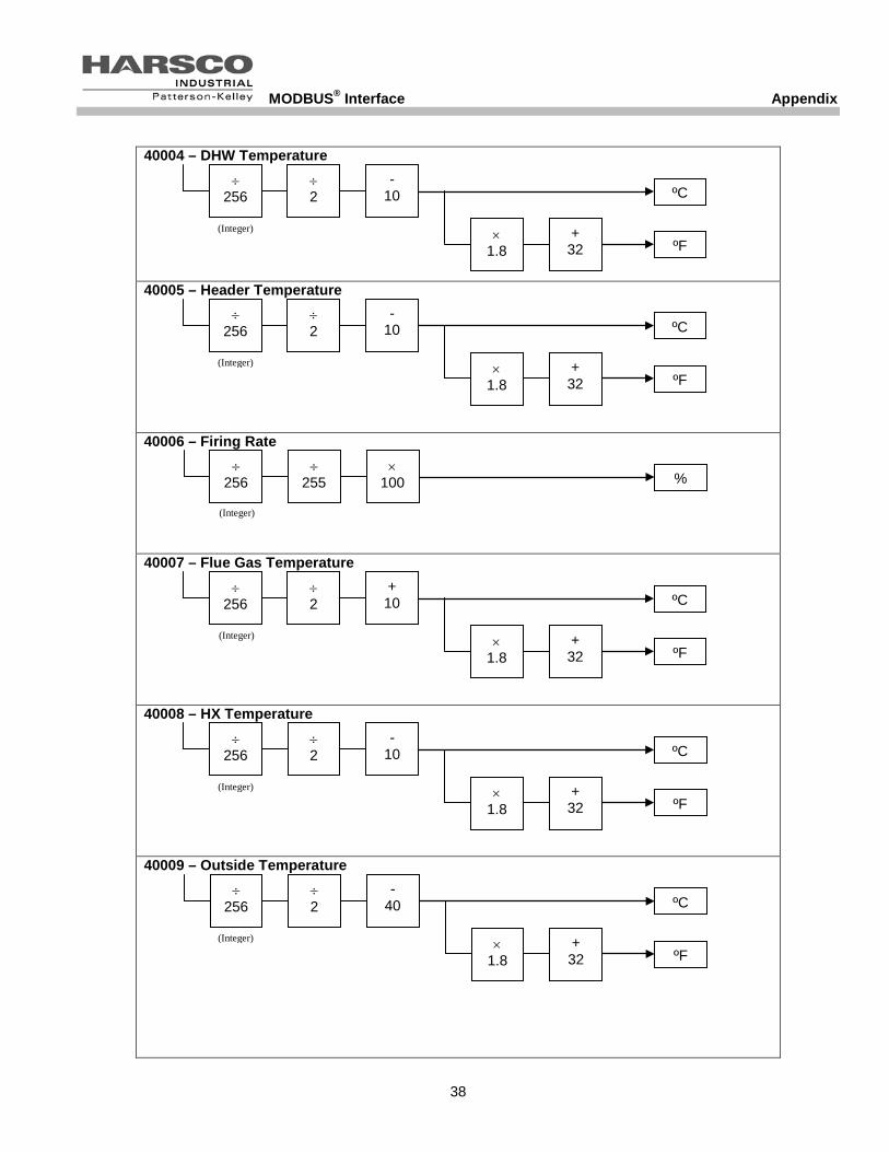
Address Byte Type Parameter Name Formula/Data 0 HIGH State See State Table 0 LOW Supply Temperature Normal Temperature 2 HIGH Return Temperature Normal Temperature 2 LOW DHW Temperature Normal Temperature 4 HIGH Header Temperature Normal Temperature 4 LOW Firing Rate 1 = min to 255 = max 6 HIGH Flue Gas Temperature Flue Gas
Temperature 6 LOW HX Temperature Normal Temperature 8 HIGH Outside Temperature Outdoor Temperature 8 LOW Flame Signal 0x00 = no flame
0x80 = flame 10 HIGH CH Setpoint Normal Temperature 10 LOW DHW Setpoint Normal Temperature 12 HIGH Boiler Operation 0 = Off, 1 = On
2 = Off & pump on 3 = On & pump off
12 LOW High Outdoor Air Temperature Outdoor Temperature 14 HIGH Minimum Outdoor Air Setpoint Normal Temperature 14 LOW Low Outdoor Air Temperature Outdoor Temperature 16 HIGH Maximum Outdoor Air Temperature Normal Temperature 16 LOW Outdoor Air Shutdown Temperature Outdoor Temperature 18 HIGH Night Setback Delta Temperature 18 LOW Error Code See Error List
Section 3.2 and 3.3

MODBUS® Interface Appendix
33
20 HIGH Analog In 20 LOW Analog Out 22 BOTH Ignitions 1/16th of Ignitions 24 BOTH Burner High Hours Hours 26 BOTH Burner Medium Hours Hours 28 BOTH Burner Low Hours Hours 30 HIGH Information Byte See Information Byte 30 LOW ET Error Number See Error List
Section 3.2 and 3.3 32 HIGH ET Supply Temp Normal Temperature 32 LOW ET Return Temp Normal Temperature 34 HIGH ET DHW Temp Normal Temperature 34 LOW ET Flue Temp Flue Gas
Temperature 36 HIGH ET HX Temp Normal Temperature 36 LOW ET Outside Temp Outdoor Temperature 38 HIGH ET Sequence See Sequence Byte 38 LOW ET Month See BCD Byte 40 HIGH ET Day See BCD Byte 40 LOW ET Year See BCD Byte 42 HIGH ET Hours See BCD Byte 42 LOW ET Minutes See BCD Byte 44 HIGH ET Day Count High 44 LOW ET Day Count Low 46 BOTH ET Run Hours Hours
Depending on the type of MODBUS® software used, the holding register addressing range starts either at 0x0000 or at 0x0001. If your MODBUS® software starts at 0x0000 you can use the holding register addresses shown in the tables above. If your MODBUS® software addressing range starts from 0x0001 then add 1 to the holding register addresses listed in the tables above. 4.1.1Descriptions of MODBUS® Register Map
Normal Temperature formula The temperature is scaled between -10…+118°C (14°F – 244°F). The formula to calculate the actual temperature using the value of Supply Temperature is as follows: I) Temperature [°C] = (Supply Temperature ÷ 2) - 10 II) Temperature [°F] = Temperature [°C] × 1.8 + 32 Outdoor temperature formula Some temperatures are scaled between -40°C and 88°C (-40°F – 190°F). The formula to calculate the actual temperature is: I) Temperature [°C] = (outdoor temperature ÷ 2) - 40 II) Temperature [°F] = Temperature [°C] × 1.8 + 32 Flue gas temperature formula Some temperatures are scaled between 10°C and 138 °C (50°F – 280°F. The formula to calculate the actual temperature is: I) Temperature [°C] = (flue gas temperature ÷ 2) + 10 II) Temperature [°F] = Temperature [°C] × 1.8 + 32 Delta temperature formula

MODBUS® Interface Appendix
34
When a temperature is used as a delta temperature (for instance the night setback) it is calculated as follows: I) Temperature [°C] = (night setback ÷ 2) II) Temperature [°F] = Temperature [°C] × 1.8 4.1.2Boiler State
The operation of the boiler is described by the following table of state values.
State (decimal)
State (Hexadecimal) State Name Description
0 0x00 RESET_0 Resetting 1 0x01 RESET_1 Resetting 2 0x02 STANDBY_0 Standby, waiting for demand 3 0x03 SAFETY_ON Relay circuit check 4 0x04 SAFETY_OFF Relay circuit check 5 0x05 PRE_PURGE Pre purging 6 0x06 PRE_PURGE_1 Pre purging 7 0x07 IGNIT_0 Pre ignition with gas valve closed 8 0x08 IGNIT_1 Ignition with gas valve open 9 0x09 BURN_0 Burning 10 0x0A POST_PURGE_0 Post purging burner 11 0x0B POST_PURGE_1 Post purging burner 12 0x0C PUMP_CH_0 Post pumping for CH 13 0x0D PUMP_CH_1 Pumping for CH 14 0x0E PUMP_HW_0 Post pumping for DHW 15 0x0F PUMP_HW_1 Pumping for DHW 16 0x10 ALARM_1 Error handling (locking) 17 0x11 ERROR_CHECK Error Handling (blocking) 18 0x12 BURNER_BOOT Restarting burner control 19 0x13 CLEAR_E2PROM_ERROR Error handing 20 0x14 STORE_BLOCK_ERROR Error handling 21 0x15 WAIT_A_SECOND Error handling
4.1.3 Information Byte
Every bit in the byte is a flag. When the flag is 1 it means closed/running when it is 0 it means Open/stopped. In the following table you can find the bit number of the flag. Bit 7 Bit 6 Bit 5 Bit 4 Bit 3 Bit 2 Bit 1 Bit 0 High Gas Pressure
Air Damper DHW Pump CH Pump Blocked Flue
Air Pressure
Low Gas Pressure
Water Level
4.1.4Sequence Byte
The following table details the sequence byte. This byte consists of the state of the boiler and operation mode of the boiler, both at the time of the error. Bit 7 Bit 6 Bit 5 Bit 4 Bit 3 Bit 2 Bit 1 Bit 0 1 = CH Mode
1 = DHW Mode
1 = Frost Protect
state state state state state

MODBUS® Interface Appendix
35
ENVI® CONTROLS: MODBUS® CONFIGURATION
The following parameters are required to establish MODBUS® communication:
Protocol MODBUS® RTU Supported MODBUS® Commands Read Holding Register (0x03)
Write Single Holding Register (0x06) Baudrate 9600 bps Data Length 8 Parity None Stop Bits 1 Register Request 1 Physical Layer RS485 (two wire)
Some MODBUS® programs such as ModScan32 start the address registers at 40001:
Other MODBUS® programs such as QModBus start the address registers at 40000:

MODBUS® Interface Appendix
36
Notice how the decimal values are equivalent (4257) in both programs. These procedures assume the MODBUS® program starts the address registers at 40001. If the program starts the address registers at 40000, subtract one from the address register shown in each procedure. The procedures described in this bulletin require the user to pull a single MODBUS® register from one boiler at any given time. Multiple register requests or simultaneous register requests from multiple boilers are not discussed in this bulletin. It is also important to note that different MODBUS® programs will display data in hexadecimal, decimal or binary format. These procedures require all addresses to be displayed as decimal values. In addition, there are several procedures which require integer division. These particular operations are indicated by (Integer) and two examples of standard division vs. integer division are shown below:
• Standard Division: o 40869 ÷ 256 = 159.644
• Integer Division: o 40869 ÷ 256 = 159
• Standard Division: o 15 ÷ 1.8 = 8.333
• Integer Division: o 15 ÷ 1.8 = 8
Useful abbreviations:
• CH = Comfort Heat • DHW = Domestic Hot Water • ET = Error Text • HX = Heat Exchanger • OA = Outdoor Air
The E-104 MODBUS Calculator.xls Excel spreadsheet will be very helpful in performing the calculations shown in the procedures below. This is available under the “Technical Data” section of www.harscopk.com.

MODBUS® Interface Appendix
37
5.0 MODBUS CONFIGURATION ENVI® CONTROLS: READ-ONLY MODBUS® REGISTERS
MODBUS® READ-ONLY REGISTER MAP 40001 – State
Decimal Hex STATE NAME Description
1 0x01 RESET_1 Resetting
2 0x02 STANDBY_0 Standby, waiting for demand
3 0x03 SAFETY_ON Relay circuit check
4 0x04 SAFETY_OFF Relay circuit check
5 0x05 PRE_PURGE Pre purging
6 0x06 PRE_PURGE_1 Pre purging
7 0x07 IGNIT_0 Pre ignition with gas valve closed
8 0x08 IGNIT_1 Ignition with gas valve open
9 0x09 BURN_0 Burning
10 0x0A POST_PURGE_0 Post purging
11 0x0B POST_PURGE_1 Post purging
12 0x0C PUMP_CH_0 Post pumping for CH
13 0x0D PUMP_CH_1 Pumping for CH
14 0x0E PUMP_HW_0 Post pumping for DHW
15 0x0F PUMP_HW_1 Pumping for DHW
16 0x10 ALARM_1 Error handling (locking)
17 0x11 ERROR_CHECK Error handling (blocking)
18 0x12 BURNER_BOOT Restarting burner control
19 0x13 CLEAR_E2PROM_ERROR Error handling
20 0x14 STORE_BLOCK_ERROR Error handling
21 0x15 WAIT_A_SECOND Error handling
40002 – Supply Temperature 40003 – Return Temperature
÷ 256
(Integer)
(Integer)
÷ 256
÷ 2
+ 32 ºF
× 1.8
- 10 ºC
÷ 256
÷ 2
+ 32 ºF
× 1.8
- 10 ºC
(Integer)
MODBUS® Interface Appendix
38
40004 – DHW Temperature 40005 – Header Temperature 40006 – Firing Rate 40007 – Flue Gas Temperature 40008 – HX Temperature 40009 – Outside Temperature
÷ 256
÷ 255
× 100 %
(Integer)
÷ 256
÷ 2
+ 32 ºF
× 1.8
- 10 ºC
(Integer)
÷ 256
÷ 2
+ 32 ºF
× 1.8
- 10 ºC
(Integer)
÷ 256
÷ 2
+ 32 ºF
× 1.8
- 10 ºC
(Integer)
(Integer)
÷ 256
÷ 2
+ 32 ºF
× 1.8
- 40 ºC
÷ 256
÷ 2
+ 32 ºF
× 1.8
+ 10 ºC
(Integer)

MODBUS® Interface Appendix
39
40010 – Flame Signal
DECIMAL Hex Description
0 0x00 No Flame
128 0x80 Flame
40011 – CH Setpoint 40012 – DHW Setpoint 40013 – Boiler Operation
DECIMAL Hex Description
0 0x00 Boiler OFF & Pump OFF
1 0x01 Boiler ON & Pump ON
2 0x02 Boiler OFF & Pump ON*
3 0x03 Boiler ON & Pump ON*
ON* indicates pump is on constantly
40014 – High Outdoor Air Temperature
÷ 256
(Integer)
÷ 256
(Integer)
÷ 256
÷ 2
+ 32 ºF
× 1.8
- 40 ºC
(Integer)
÷ 256
÷ 2
+ 32 ºF
× 1.8
- 10 ºC
(Integer)
÷ 256
÷ 2
+ 32 ºF
× 1.8
- 10 ºC
(Integer)
MODBUS® Interface Appendix
40
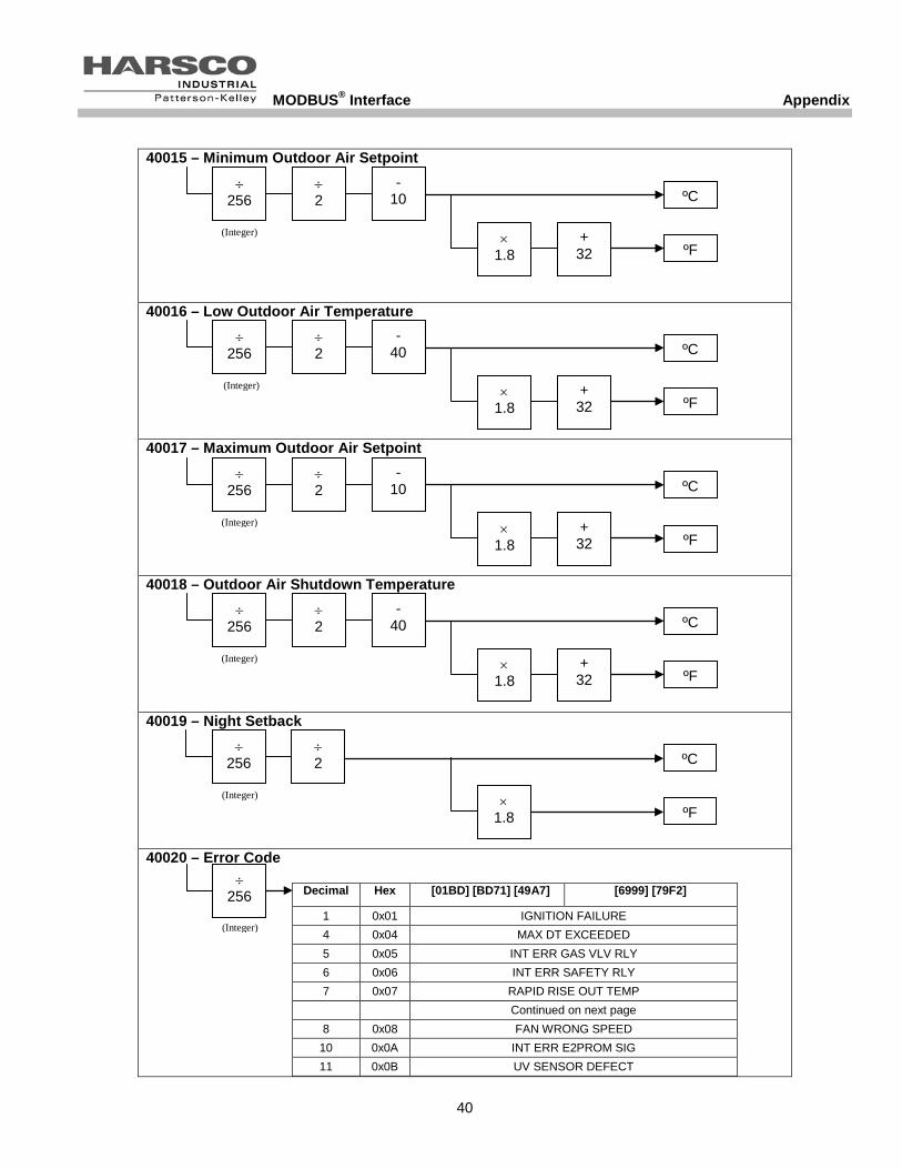
40015 – Minimum Outdoor Air Setpoint 40016 – Low Outdoor Air Temperature 40017 – Maximum Outdoor Air Setpoint 40018 – Outdoor Air Shutdown Temperature 40019 – Night Setback 40020 – Error Code
Decimal Hex [01BD] [BD71] [49A7] [6999] [79F2]
1 0x01 IGNITION FAILURE 4 0x04 MAX DT EXCEEDED 5 0x05 INT ERR GAS VLV RLY 6 0x06 INT ERR SAFETY RLY 7 0x07 RAPID RISE OUT TEMP Continued on next page 8 0x08 FAN WRONG SPEED
10 0x0A INT ERR E2PROM SIG 11 0x0B UV SENSOR DEFECT
÷ 256
÷ 2
ºF ×
1.8
ºC
(Integer)
÷ 256
÷ 2
+ 32 ºF
× 1.8
- 40 ºC
(Integer)
÷ 256
÷ 2
+ 32 ºF
× 1.8
- 40 ºC
(Integer)
÷ 256
÷ 2
+ 32 ºF
× 1.8
- 10 ºC
(Integer)
÷ 256
÷ 2
+ 32 ºF
× 1.8
- 10 ºC
(Integer)
÷ 256
(Integer)

MODBUS® Interface Appendix
41
12 0x0C INT ERR E2PROM ERR 15 0x0F RAPID RISE INLET TEMP 16 0x10 INTERNAL ERROR 16 17 0x11 RAPID RISE HX TEMP 18 0x12 HIGH LIMIT 20 0x14 LATE FLAME 21 0x15 EARLY FLAME 24 0x18 FLAME FAILURE 25 0x19 AIR SWITCH NOT OPEN 26 0x1A AIR SWITCH NOT CLOSE 30 0x1E LOW WATER LEVEL INTERNAL ERROR 30 31 0x1F LOW GAS PRESSURE INTERNAL ERROR 31 32 0x20 HIGH GAS PRESSURE INTERNAL ERROR 32 35 0x23 INTERNAL ERROR 32 HIGH FLUE TEMP 36 0x24 INTERNAL ERROR 33 FALSE FLAME 37 0x25 INTERNAL ERROR 34 LOW WATER LEVEL 38 0x26 HIGH FLUE TEMP LOW GAS PRESSURE 39 0x27 FALSE FLAME BLOCKED FLUE 40 0x28 BLOCKED FLUE HIGH INLET TEMP 41 0x29 HIGH INLET TEMP REVERSE FLOW IN OUT 42 0x2A REVERSE FLOW IN OUT N/A 43 0x2B N/A NO GROUND 60 HZ ERR 44 0x2C NO GROUND 60 HZ ERR LINE NEUTRAL REV 45 0x2D LINE NEUTRAL REV LINE FREQUENCY ERR 46 0x2E LINE FREQUENCY ERR FAULTY GROUND 47 0x2F FAULTY GROUND INTERNAL ERROR 47 48 0x30 INTERNAL ERROR 47 WRONG BOILER TYPE 49 0x31 WRONG BOILER TYPE RAPID RISE HX ERROR 50 0x32 RAPID RISE HX ERROR N/A 51 0x33 N/A OUT TEMP SENS OPEN 52 0x34 OUT TEMP SENS OPEN IN TEMP SENS OPEN 53 0x35 IN TEMP SENS OPEN N/A 55 0x37 N/A DHW TEMP SENS OPEN 56 0x38 DHW TEMP SENS OPEN HX TEMP SENS OPEN 57 0x39 HX TEMP SENS OPEN FLUE TMP SENS OPEN 58 0x3A FLUE TMP SENS OPEN N/A 59 0x3B N/A OUT TEMP SENS SHORT 60 0x3C OUT TEMP SENS SHORT IN TEMP SENS SHORT 61 0x3D IN TEMP SENS SHORT N/A 63 0x3F N/A DHW TEMP SENS SHORT 64 0x40 DHW TEMP SENS SHORT HX TEMP SENS SHORT 65 0x41 HX TEMP SENS SHORT FLUE TMP SENS SHORT 66 0x42 FLUE TMP SENS SHORT INTERNAL ERROR 66 67 0x43 INTERNAL ERROR 66 HIGH GAS PRESSURE 68 0x44 IF COMM FAILURE Continued on next page
69 0x45 HEADER SENS OPEN 70 0x46 HEADER SENS SHORT 71 0x47 RAPID RISE ERROR

MODBUS® Interface Appendix
42
• These error code descriptions may vary depending on which version of the ENVI®
controls are installed on the boiler. To check the software version of the ENVI® controls: o Press MENU o Press DOWN three times to scroll to “Configuration” and press ENTER o Press DOWN twice to scroll to “Code” and press ENTER
40021 – Analog In 40022 – Analog Out 40023 – Ignitions 40025 – Burner High Hours
• Hours spent between 75% and 100% firing rate 40027 – Burner Medium Hours
• Hours spent between 45% and 75% firing rate 40029 – Burner Low Hours
• Hours spent between 20% and 45% firing rate 40031 – Information Byte
• Convert decimal value to binary BIT 7 Bit 6 Bit 5 Bit 4 Bit 3 Bit 2 Bit 1 Bit 0
High Gas Pressure Air Damper DHW Pump CH Pump Blocked
Flue Air
Pressure Low Gas Pressure Water Level
40032 – ET Error Number
• Refer to 40020 – Error Code (above)
× 16 #
÷ 256
÷ 255
× 10 V
(Integer)
÷ 256 #
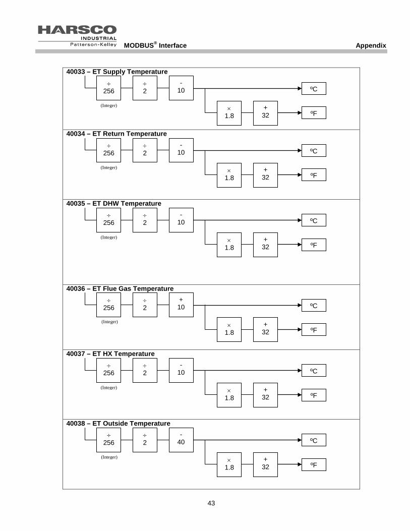
MODBUS® Interface Appendix
43
40033 – ET Supply Temperature 40034 – ET Return Temperature 40035 – ET DHW Temperature 40036 – ET Flue Gas Temperature 40037 – ET HX Temperature 40038 – ET Outside Temperature
÷ 256
÷ 2
+ 32 ºF
× 1.8
+ 10 ºC
(Integer)
÷ 256
÷ 2
+ 32 ºF
× 1.8
- 40 ºC
(Integer)
÷ 256
÷ 2
+ 32 ºF
× 1.8
- 10 ºC
(Integer)
÷ 256
÷ 2
+ 32 ºF
× 1.8
- 10 ºC
(Integer)
÷ 256
÷ 2
+ 32 ºF
× 1.8
- 10 ºC
(Integer)
÷ 256
÷ 2
+ 32 ºF
× 1.8
- 10 ºC
(Integer)

MODBUS® Interface Appendix
44
40039 – ET Sequence
• Convert decimal value to binary BIT 7 Bit 6 Bit 5 Bit 4 Bit 3 Bit 2 Bit 1 Bit 0
1 = CH Mode
1 = DHW Mode
1 = Frost Protection State State State State State
• Bit 0 thru Bit 4 provide the Boiler State at the time of the error
o (Example: 01101 = 13 = Post Pump CH)
• Bit 5 indicates if the boiler was operating in Frost Protection mode at the time of the error
• Bit 6 indicates if the boiler was operating in DHW mode at the time of the error
• Bit 7 indicates if the boiler was operating in CH mode at the time of the error
40040 – ET Month 40041 – ET Day 40042 – ET Year 40043 – ET Hours 40044 – ET Minutes
• Convert the decimal values to hexadecimal values to find December, 25th 2011:
o ET Month (Decimal 18 = Hexadecimal 12 = December)
o ET Day (Decimal 37 = Hexadecimal 25 = 25th)
o ET Year (Decimal 17 = Hexadecimal 11 = 2011)
40045 – ET Day Count High 40046 – ET Day Count Low 40047 – ET Run Hours
• Accumulated run hours at the time of the error.
÷ 256 #
(Integer)
÷ 256 #
÷ 256 #
(Integer)

MODBUS® Interface Appendix
45
ENVI® CONTROLS: WRITE-ONLY MODBUS® REGISTERS It is important to note that the ENVI
® controls require the user to write two values simultaneously to a single register.
For example, if the operator wants the CH Setpoint to be 140°F and the DHW Setpoint to be 180°F and the user follows the 40011 procedure below, the decimal value to be written is (35840 + 184 = 36024). Refer to the M-104 MODBUS Calculator.xls spreadsheet to help with these calculations. MODBUS® WRITE-ONLY REGISTER MAP 40011 – CH Setpoint & DHW Setpoint 40013 – Boiler Operation & High Outdoor Air Temperature 40015 – Minimum Outdoor Air Setpoint & Low Outdoor Air Temperature
CH Setpoint °F
+ 10
- 32
÷ 1.8
× 512
(Integer)
+
DHW Setpoint °F
+ 10
- 32
÷ 1.8
× 2
(Integer)
Min OA Setpoint °F
+ 10
- 32
÷ 1.8
× 512
(Integer)
+
+ 40
- 32
÷ 1.8
× 2
(Integer)
Low OA Temperature °F
× 256
+
High Outdoor Air Temperature °F
+ 40
- 32
÷ 1.8
× 2
(Integer)
Boiler Operation (0, 1, 2 or 3)

MODBUS® Interface Appendix
46
40017 – Maximum Outdoor Air Temperature & Outdoor Air Shutdown Temperature 40018 – Outdoor Air Shutdown Temperature & Night Setback
(Integer)
+ 10
- 32
÷ 1.8
× 512
(Integer)
+
+ 40
- 32
÷ 1.8
× 2
OA Shutdown Temperature °F
Max OA Temperature °F
(Integer)
+ 40
- 32
÷ 1.8
× 512
+
÷ 1.8
× 2
OA Shutdown Temperature °F
Night Setback °F
(Integer)

MODBUS® Interface Appendix
47