böning catalog ship automation - boening.com€¦ · 4 company profile devices, systems,...
TRANSCRIPT

CatalogShip Automation
Systems and Devices for Monitoring and Control Technology

2
CON
TEN
TS
ContentsDevices, Systems, Monitoring
and Control Systems for Ship Automation ������������������������� 4
Integrated Alarm, Monitoring,
and Control System ����������������������������������������������������������� 6
Configuration and Diagnostic Software ���������������������������� 8
Visualization Examples ������������������������������������������������������ 9
Visualizations for 8�8” Displays �����������������������������������������12
Displays and Panel Computers for Maritime Use ��������������14
Display Control Units ������������������������������������������������������� 23
Data Stations, Control and Switching Units ��������������������� 26
Remote Monitoring and Fault Detection ������������������������� 35
BIBS – Integrated Bridge System �������������������������������������� 42
Operation Panels ������������������������������������������������������������� 44
Engine Start/Stop Systems ����������������������������������������������� 50
Monitoring and Control Systems
for Navigation Lanterns ��������������������������������������������������� 54
CCTV Video Monitoring System �������������������������������������� 60
Trim Tabs Control System ������������������������������������������������ 70
Diesel Engine Monitoring
and Safety Systems �����������������������������������������������������������74
Engine Monitoring Systems ��������������������������������������������� 79
On-Duty / Engineer Call System ��������������������������������������� 80
Standby Pumps and Compressor Controls ����������������������� 82
Bow Thruster Control ������������������������������������������������������ 84
Device Index �������������������������������������������������������������������� 86
Contact Information �������������������������������������������������������� 87

4
COM
PAN
Y PR
OFI
LE
Devices, Systems, Monitoring and Control Systems for Ship Automation
Our company’s founding stone was laid in 1977 with
the establishment of the Engineering Firm Böning�
In 1996, it became the Engineering Firm Böning
GmbH, which was renamed to Böning Automations-
technologie GmbH & Co� KG in 2003� From the very
beginning, the development and manufacture of
electronic devices and systems for ship automation
was a major focal point of all company activities�
Originally rooted in commercial shipping, we have also
been successfully active in the area of super and mega
yachts since 1996� In the meantime, our devices and
systems, the majority of which we have developed
and manufactured ourselves by the way, are found
on more than 13,000 commercial ships and yachts�

5
COMPANY PROFILE
COM
PAN
Y PR
OFI
LE
By now, a staff of approximately 100, among them
about 20 engineers in the area of development alone,
are employed here in Ganderkesee in an area of nearly
4000 m² for office, production, and storage space�
One of our responses to the economic crisis beginning
in 2008 is our continued drive toward globalization�
In this context, we point to branch offices in Brazil,
Italy, and Croatia, as well as representatives and
distribution partners� This allows us to better meet
the demands for competent service and short routes,
especially by shipping companies and yacht owners�
One of our recipes for success is based on the close
cooperation with our customers, resulting in creation of
practice-oriented and reliable devices and systems� From
this positive synergy grows a steady expansion of our
competence� Here, we point out especially the integrated
alarm systems which affect practically all areas of ships�
Safety relevant devices and systems are generally
type approved according to Germanischer Lloyd
and other classification societies�
Our company is DIN EN ISO 9001:2008 certified�
6
INTE
GRA
TED
ALA
RM, M
ON
ITO
RIN
G A
ND
CO
NTR
OL
SYST
EM
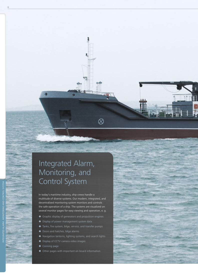
Integrated Alarm, Monitoring, and Control SystemIn today’s maritime industry, ship crews handle a
multitude of diverse systems� Our modern, integrated, and
decentralized monitoring system monitors and controls
the safe operation of a ship� The systems are visualized on
several monitor pages for easy viewing and operation, e� g�
® Graphic display of generators and propulsion engines
® Display of power management system data
® Tanks, fire system, bilge, service, and transfer pumps
® Doors and hatches, bilge alarms
® Navigation lanterns, lighting systems, and search lights
® Display of CCTV camera video images
® Conning page
® Other pages with important on-board information

7
INTE
GRA
TED
ALA
RM, M
ON
ITO
RIN
G A
ND
CO
NTR
OL
SYST
EM
INTEGRATED ALARM, MONITORING AND CONTROL SYSTEM

8
INTE
GRA
TED
ALA
RM, M
ON
ITO
RIN
G A
ND
CO
NTR
OL
SYST
EM
Configuration and Diagnostic Software
AHD-DeviceConfig is a software tool for the
uniform and complete system configuration of all
Böning alarm, monitoring, and control systems�
The configuration is generally based on a customer
generated, project specific measuring points list�
With our configuration tool AHD-DeviceConfig,
our devices and systems can be configured over
a network� Additionally, firmware updates can
be executed and diagnostic information can be
viewed� The tool AHD-MiniCAN is available
for further reaching diagnostics options�
With AHD-DisplayDesigner, individual
visualization pages can be created, configured, and
transferred to the devices over the network�

9
INTE
GRA
TED
ALA
RM, M
ON
ITO
RIN
G A
ND
CO
NTR
OL
SYST
EM
INTEGRATED ALARM, MONITORING AND CONTROL SYSTEM
Visualization ExamplesModern ships are equipped with numerous different
systems that must be monitored and controlled�
Our displays present the vessel’s data visually
and logically on various pages� The ship crew
simply navigates the pages to view the data� Just like in your car: The display provides information about the engine’s state, using customary display systems� The engine data are displayed on round instruments and in numeric presentation�
A menu page shows all available system pages with the option to launch the desired page directly�
On-board power grid monitoring, including generators and battery chargers�
The bar graph presentation makes for easier reading of important engine parameters, thus allowing for quick visual comparisons�
Like having the skipper himself in the ECR: Access to all engine data at a glance often saves a trip to the ECR�

10
INTE
GRA
TED
ALA
RM, M
ON
ITO
RIN
G A
ND
CO
NTR
OL
SYST
EM
Representation of the battery charge states�
Representation of a bilge system�
Overview of several important operational data�
Fuel, water, oil, and other resources are carried along in tanks most of the time – as well as waste water and sewage� Bar graphs display the tanks’ filling levels states� The pumps can also be controlled from this page�
Remote control for air conditioning systems, lights, and blinds on a single page, displayed in switchable deck views�
Navigation and signal lantern control and monitoring�

11
INTE
GRA
TED
ALA
RM, M
ON
ITO
RIN
G A
ND
CO
NTR
OL
SYST
EM
INTEGRATED ALARM, MONITORING AND CONTROL SYSTEM
A centralized lighting control and monitoring system is not only convenient but also efficient�
Page for visualizing the status of doors, hatches and ladders�
Grouping of all alarms on a separate page�
It is good to know what happens on board or in the close vicinity� Cameras in selected places monitor the corresponding areas� Comfortably controlled from the bridge, the display shows the desired images� Up to four fields can be viewed simultaneously on the display�
Conning page with navigational round instruments, such as air pressure, air temperature, humidity, COG, SOG, roll-pitch-yaw angle, and water depth�
All events falling into a certain time interval are displayed in a table� Thus, the crew has access to a continuous overview of the events�

12
INTE
GRA
TED
ALA
RM, M
ON
ITO
RIN
G A
ND
CO
NTR
OL
SYST
EM
Visualizations for 8�8” DisplaysThe following visualization examples have been designed
for the AHD 880 series displays� The graphics were created
with the AHD-DisplayDesigner software with which
customer specific display pages can be created�
Once the system is launched, the menu page with direct links to various pages in the system is displayed�
General engine status information, e�g� engine speed, oil pressure, and cooling water temperature are displayed on the engine page�
The ship’s lighting system can be controlled from this page� Brightness levels can be set seamlessly with slide controllers� Preconfigured lighting groups can be switched together�
Visualization and control of generators and power supply� Tank contents measuring for fuel, drinking water, grey water, and black water�

13
INTE
GRA
TED
ALA
RM, M
ON
ITO
RIN
G A
ND
CO
NTR
OL
SYST
EM
INTEGRATED ALARM, MONITORING AND CONTROL SYSTEM
For increased on-board safety, the lighting in predefined areas can be conveniently switched on or off�
Navigation lanterns must be monitored continuously� A visualization on a display showing lantern states, error indica-tion, and much more offers many advantages when compared to traditional displays� Combined with our navigation lantern monitoring system, an easy to use and type-approved system is at your disposal�
The visualization shows the states of the bilge pumps in the various ship areas�
At a single glance: all necessary information about position, cruising speed, and heading�
An alarm page provides a list of all incoming alarms and warnings, including measuring point designation, value, and alarm time�
Transferring fluids from one tank to another is easy and simple with a clearly organized visualization of the respective systems� Pump and valve control is designed based to the vessel’s requirements�
Language, time, and date, etc� are adjusted on the settings page�
Remote controlled cameras in selected ship locations contribute to increased safety on board� The CCTV system consists of several cameras whose images are shown on the display� Expansions, such as recording functions, are optionally available�

14
MA
RIN
E D
ISPL
AYS
AN
D C
OM
PUTE
RS
The displays’ main functions are identical throughout
the entire product line� The brightness is always
matched to the ambient light, ensuring glare-free
operation while cruising at night and optimum readability
during sunlight� The displays can be integrated flush
and watertight into consoles and switch boards�
Most displays include an integrated touch
screen and can be easily operated with
control panels (beginning on page 24)�
Dispensing with mechanically movable parts
ensures maintenance free hardware that is
impact resistant and completely noiseless�
Our panel PCs also provide the option of
showing the image data from external
imaging sources via external inputs�
Displays and Panel Computers for Maritime UseAll displays in our product line were designed
with the goal of providing the best possible
platform for graphic user interfaces�
Our displays appeal through design, intuitive opera-
tion, and individualized visualization options�
Data from external systems can be captured and
processed with ports that meet the requirements
of the modern maritime industry,�
The monitors of the 11-series (10”, 15”, 19”, 24”) are
especially suited as display devices for external sources�
On the other hand, the panel PCs of the 12-series
(15”, 19”, 24”) combine the same, excellent display
properties with an integrated, powerful PC system�

15
MA
RIN
E D
ISPL
AYS
AN
D C
OM
PUTE
RS
MARINE DISPLAYS AND COMPUTERS
AHD 1219 G / AHD 1215 G
LCD-Panel PC-System with Glass Front and Touch Screen
Integrated panel PC system with glass front, provides
a central visualization and operation platform for
alarm and monitoring systems� The large 19” and
15” screens provide sufficient room for presenting
complex correlations, even within the context of
extensive systems� High capacity, increased functio-
nality, and appealing design contribute to an increase
in operational safety and comfort on ship bridges�
The panel PC system was developed specifically for
maritime use� Dispensing with mechanically movable
parts and equipping the unit with a passive cooling
system secures error-free operation even under
extreme conditions� The integrated PC runs on a
self-contained XP Embedded® operating system� This
prevents any changes during normal operation and
thus, it runs with the highest degree of stability�
The excellent color graphics monitor with integrated
touchscreen operation facilitates coverage of any incurring
visualization and control tasks on board� High luminosities
ensure the best readability even during strong sunlight�
When cruising at night, automatic dimming with variable
minimum brightness ensures glare-free operation�
Frontside touch fields allow for direct acknowledge-
ment of active alarms, selection of the video source,
as well as a default-setting function� The remote
control units AHD DRM R (Control Unit for Color
Displays and Monitors with Rotary Push Drive) or
AHD DRM T (Control Unit for Color Displays and Monitors
with Trackball) provide additional control options�
Version with black glass front, suitable for bulk-
head or flush mounting� Alternatively, available
with white glass front� (item-no� 14060)
AHD 1219 G
Inputs
1 x DVI-D In, 1x VGA In,
1 x Video-In (BNC, PAL 50 Hz),
4 x Digital IN (optocoupler)
Outputs 5 x Digital OUT (relay output)
Interfaces6 x CAN (galvanically isolated),
1 x RS-232, 2 x LAN, 2 x USB 2�0
Power supply 24 V DC (+30% / -25%)
Current consumption 2�5 A @ 24 V DC
Dimensions (W x H x D) 454 mm x 384 mm x 107 mm
Degree of ProtectionIP 66 (front)
IP 20 (rear)
Weight approx� 12 kg
Processor1�3 GHz DualCore,
4 GB RAM, 4 GB Flash Disk
Display resolution SXGA 1280 x 1024 pixels (5:4)
Viewing angle Hor� 89/89°; Vert� 89/89°
Luminous intensity
approx� 1,000 cd/m²
Best readability at all ambient
light conditions
Display illuminationLED back light manually or
automatically controllable
Operation temperature
-25 °C … +55 °C
(-25 °C … +70 °C at interior
console temp� of max�+45°C)
Storage temperature-50 °C … +85 °C
(according to RMRS Part IV Section 3�10)
ApprovalsGL, LR, BV, DNV, ABS, RMRS,
RINA, CRS (in progress)
AHD 1215 G Deviations
Current consumption 2�1 A @ 24 V DC
Dimensions (W x H x D) 384 mm x 324 mm x 107 mm
Weight approx� 10 kg
Display resolution XGA 1024 x 768 pixels (4:3)
Viewing angle Hor� 70/40°; Vert� 70/70°
Luminous intensity approx� 1,600 cd/m²
Large image top left:
AHD 1219 G black (item-no� 14059)
Top:
AHD 1219 G white (item-no� 14060)
Top right:
AHD 1215 G black (item-no� 14058)
Right:
AHD 1215 G white (item-no� 14057)

16
MA
RIN
E D
ISPL
AYS
AN
D C
OM
PUTE
RS
AHD 1224 G item-no� 14086
24" Widescreen Panel PC with Glass front
AHD 1224 G differences compared to AHD 1219 G
Current consumption 2�5 A @ 24 V DC
Dimensions (W x H x D) 620 mm x 390 mm x 107 mm
Weight approx� 15 kg
Display resolution Full HD 1920 x 1080 pixels (16:9)
Viewing angle Hor� 89/89°; Vert� 89/89°
Luminous intensity
approx� 1,000 cd/m²
Best readability at all ambient
light conditions
Inputs
4 x optocoupler input)
(alarm acknowledgment,
special functions optional)
Outputs5 x relay output (switch contacts,
galvanically isolated)
Interfaces
6 x CAN (galvanically isolated),
1 x RS-232, 2 x LAN,
2 x USB 2�0, 1 x VGA out,
1 x DVI-D out, 1 x DVI-D in,
1 x video-in (BNC, PAL 50 Hz)
Power supply 24 V DC (+30% / -25%)
Current consumption 1�9 A @ 24 V DC
Dimensions (W x H x D) 400 mm x 320 mm x 112 mm
Degree of Protection IP 20
Weight approx� 10 kg
Processor
1�6 GHz DualCore,
4 GB RAM, 4 GB SSD Hard Disk,
Windows XP® Embedded
Supported standard
Display resolutions
SXGA 1280 x 1024 pixels (5:4)
XGA 1024 x 768 pixels (4:3)
Operation temperature -25 °C … +55 °C
Storage temperature -50 °C … +85 °C
Approvals GL
AHD 1200 item-no� 14486
PC System (Black box)
Blackbox computer system for console installation or flush
mounting with integrated, powerful PC system, can be
used for data management and visualization, as a platform
for alarm and monitoring systems or as a central control
system; innovative operation and visualization concept;
intuitive user interface; customer specific graphics can
be integrated; video functions: overlay of standard video
signals or switch to DVI input; suitable for controlling the
display series AHD 1115 (15”), AHD 1119 (19”), or external
displays with matching resolution�
® Robust design with passive cooling system
without mechanically movable parts
® Shock-resistant and silent
® Electronic unit in metallic housing
® All device connections plugable

17
MA
RIN
E D
ISPL
AYS
AN
D C
OM
PUTE
RS
MARINE DISPLAYS AND COMPUTERS
AHD 1219 F
Inputs
1 x DVI-D In, 1x VGA In,
1 x Video-In (BNC, PAL 50 Hz),
4 x Digital IN (optocoupler)
Outputs 5 x Digital OUT (relay output)
Interfaces6 x CAN (galvanically isolated),
1 x RS-232, 2 x LAN, 2 x USB 2�0
Power supply 24 V DC (+30% / -25%)
Current consumption 2�5 A @ 24 V DC
Dimensions (W x H x D) 454 mm x 384 mm x 107 mm
Degree of ProtectionIP 66 (front)
IP 20 (rear)
Weight approx� 12 kg
Processor1�3 GHz DualCore,
4 GB RAM, 4 GB Flash Disk
Display resolution SXGA 1280 x 1024 pixels (5:4)
Viewing angle Hor� 89/89°; Vert� 89/89°
Luminous intensity
approx� 1,000 cd/m²
Best readability at all ambient
light conditions
Display illuminationLED back light manually or
automatically controllable
Operation temperature
-25 °C … +55 °C
(-25 °C … +70 °C at interior
console temp� of max�+45°C)
Storage temperature-50 °C … +85 °C
(according to RMRS Part IV Section 3�10)
ApprovalsGL, LR, BV, DNV, ABS, RMRS,
RINA, CRS (in progress)
AHD 1215 F Deviations
Display with integrated touch surface
Current consumption 2�1 A @ 24 V DC
Dimensions (W x H x D) 384 mm x 324 mm x 107 mm
Weight approx� 10 kg
Display resolution XGA 1024 x 768 pixels (4:3)
Viewing angle Hor� 70/40°; Vert� 70/70°
Luminous intensity approx� 1,600 cd/m²
AHD 1219 F / AHD 1215 F
LCD-Panel PC-System with Foil Front
Integrated panel PC system with 19” and 15” monitor,
standard version with matt black front frame�
Configuration comparable to glass front variant
(item-no� 14060) automatic dimming, processes
various video signals (DVI-D, VGA or PAL 50 Hz)�
Large image top:
AHD 1219 F (item-no� 14067)
Left:
AHD 1215 F (item-no� 14066)

18
MA
RIN
E D
ISPL
AYS
AN
D C
OM
PUTE
RS
AHD 1119 G / AHD 1115 G
LCD Color Display with Glass Front and Touch Screen
Monitoring display with glass front, provides a central
visualization and operating platform for alarm and
monitoring systems� High capacity, increased functio-
nality, and appealing design contribute to the operating
safety and comfort on ship bridges� The excellent color
graphics monitor with touch operation allows coverage
of all incurring visualization and control tasks on board�
The display was built specifically for maritime use�
Dispensing with mechanically movable parts and the use
of a passive cooling system ensure error-free operation
even under extreme conditions� High luminosities ensure
the best readability even during strong sunlight� When
cruising at night, the automatic dimming with variable
minimum brightness ensures glare-free operation�
AHD 1119 G / AHD 1115 G can process visualization data
from various video sources, which are comfortably selected
with an integrated frontside button� All touch control
commands are available at the integrated USB interface
and can be evaluated with a system PC� The control units
AHD-DC (Control Unit for Color Displays), AHD-DRM R
(Control Unit for Color Displays and Monitors with Rotary
Push Drive), or AHD-DRM T (Control Unit for Color Displays
with Trackball) provide additional remote control options�
Version with black glass front, suitable
for bulkhead or flush mounting�
Alternatively, available with white glass front
� AHD 1119 G white (item-no� 14064)
� AHD 1115 G white (item-no� 14061)
AHD 1119 G
Inputs1 x DVI-D In, 1x VGA In,
1 x Video-In (BNC, PAL 50 Hz)
Interfaces
2 x CAN (galvanically isolated),
1 x RS-232, 2 x LAN,
2 x USB 2�0 (Touch out)
Power supply 24 V DC (+30% / -25%)
Current consumption 1�9 A @ 24 V DC
Dimensions (W x H x D) 454 mm x 384 mm x 92 mm
Degree of ProtectionIP 66 (front)
IP 20 (rear)
Weight approx� 11 kg
Display resolution SXGA 1280 x 1024 pixels (5:4)
Viewing angle Hor� 89/89°; Vert� 89/89°
Luminous intensity
approx� 1,000 cd/m²
Best readability at all ambient
light conditions
Display illuminationLED back light manually or
automatically controllable
Operation temperature
-25 °C … +55 °C
(-25 °C … +70 °C at interior
console temp� of max�+45°C)
Storage temperature-50 °C … +85 °C
(according to RMRS Part IV Section 3�10)
Approvals GL, MED compliant
AHD 1115 G Deviations
Current consumption 1�7 A @ 24 V DC
Dimensions (W x H x D) 384 mm x 324 mm x 92 mm
Weight approx� 10 kg
Display resolution XGA 1024 x 768 pixels (4:3)
Viewing angle Hor� 70/40°; Vert� 70/70°
Luminous intensity
approx� 1,600 cd/m²
Best readability at all ambient
light conditions
Large image top left:
AHD 1119 G black (item-no� 14063)
Top:
AHD 1119 G white (item-no� 14064)
Top right:
AHD 1115 G black (item-no� 14062)
Right:
AHD 1115 G white (item-no� 14061)

19
MA
RIN
E D
ISPL
AYS
AN
D C
OM
PUTE
RS
MARINE DISPLAYS AND COMPUTERS
AHD 1119 F / AHD 1115 F
LCD Color Display with Foil Front
Monitoring display, standard version
with matte black front frame�
Configuration nearly identical to glass
front variant (see item-no� 14063)�
AHD 1110 F item-no� 15288
LCD Color Display with Foil Front and Touch Screen
Compact monitoring display, standard
version with matte black front frame�
AHD 1119 F
Inputs1 x DVI-D In, 1x VGA In,
1 x Video-In (BNC, PAL 50 Hz)
Interfaces
2 x CAN (galvanically isolated),
1 x RS-232, 2 x LAN,
2 x USB 2�0 (Touch out)
Power supply 24 V DC (+30% / -25%)
Current consumption 1�9 A @ 24 V DC
Dimensions (W x H x D) 454 mm x 384 mm x 92 mm
Degree of ProtectionIP 66 (front)
IP 20 (rear)
Weight approx� 11 kg
Display resolution SXGA 1280 x 1024 pixels (5:4)
Viewing angle Hor� 89/89°; Vert� 89/89°
Luminous intensity
approx� 1,000 cd/m²
Best readability at all ambient
light conditions
Display illuminationLED back light manually or
automatically controllable
Operation temperature
-25 °C … +55 °C
(-25 °C … +70 °C at interior
console temp� of max�+45°C)
Storage temperature-50 °C … +85 °C
(according to RMRS Part IV Section 3�10)
Approvals GL, MED compliant
AHD 1115 F Deviations
Display with integrated touch surface
Current consumption 1�5 A @ 24 V DC
Dimensions (W x H x D) 384 mm x 324 mm x 92 mm
Weight approx� 9 kg
Display resolution XGA 1024 x 768 pixels (4:3)
Viewing angle Hor� 70/40°; Vert� 70/70°
Luminous intensity
approx� 1,600 cd/m²
Best readability at all ambient
light conditions
AHD 1110 F Deviations
Inputs1 x DVI-D In, 1x VGA In,
1 x Video-In (BNC, PAL 50 Hz)
Interfaces
2 x CAN (galvanically isolated),
1 x RS-232, 2 x LAN,
1 x USB 2�0 (Touch out)
Power supply 24 V DC (+30% / -25%)
Current consumption 2�0 A @ 24 V DC
Dimensions (W x H x D) 280 mm x 240 mm x 107 mm
Degree of ProtectionIP 66 (front)
IP 20 (rear)
Weight approx� 7 kg
Display resolution XGA 1024 x 768 pixels (4:3)
Viewing angle Hor� 89/89°; Vert� 89/89°
Luminous intensity
approx� 1,000 cd/m²
Best readability at all ambient
light conditions
Display illuminationLED back light manually or
automatically controllable
Operation temperature
-25 °C … +55 °C
(-25 °C … +70 °C at interior
console temp� of max�+45°C)
Storage temperature-50 °C … +80 °C
(according to RMRS Part IV Section 3�10)
Large image top:
AHD 1119 F (item-no� 14070)
Left:
AHD 1115 F (item-no� 14069)

20
MA
RIN
E D
ISPL
AYS
AN
D C
OM
PUTE
RS
Transflexive display technology with brilliant display,
wide viewing angle, and full sunlight readability;
luminosity 250 cd/m2 with automatic brightness
control; integrated input for processing image or
camera signals; serial port for capturing GPS data;
connection for remote control unit AHD 650 R; buzzer
and relay contact for external signal devices�
Alternatively, available with white glass front
� AHD 880 G white (item-no� 14370)
AHD 880 TC G (including AHD 880 TC and AHD 880 E)
Inputs1 x optocoupler input
(Alarm acknowledgment)
Outputs2 x relay output (Horn, alarm,
galvanically separated)
Interfaces
3 x CAN (galvanically isolated),
1 x RS-232 (GPS),
1 x Video-In (PAL 50 Hz),
1 x RC (AHD 650 R)
Power supply 24 V DC (+30% / -25%)
Current consumption 0�7 A @ 24 V DC
Dimensions (W x H x D) 270 mm x 130 mm x 79 mm
Degree of ProtectionIP 56 (front)
IP 20 (rear)
Weight approx� 2�2 kg
Display resolution 640 x 240 pixels (8:3)
Luminous intensity
approx� 250 cd/m² transflective,
Best readability at all ambient
light conditions
Operation temperature -30 °C … +70 °C
Storage temperature -40 °C … +85 °C
Approvals GL, LR (TC and E only)
AHD 880 G item-no� 14369
8�8" Transflective Display with Glass Front and Touch Screen
The color display series AHD 880 G combines high
performance and functionality in a compact design with
atrractive glass front� It was developed specifically for
maritime use� Dispensing with mechanically movable
parts and using a passive cooling system ensures
error-free operation even under extreme conditions�
This makes the device equally suitable for outdoor
use� Due to its compact design, it can be installed
at any location where ship data should be visua-
lized or alarmed (e� g� open or closed bridge, wing
control helms, engine room, mess, or cabins)�
The display can also be used as a central presentation
platform for alarm and monitoring systems� An integrated,
latest-generation touchscreen sensor guarantees
convenience and ease of operation� All stored functions
are configured according to the requirements� Every
control relevant aspect of the ship can be displayed
in a clearly organized manner on its own page� The
visualization of status messages, measured values, and
general alarm statuses is distributed across various graphic
or tabular pages� Device in aluminum die-cast housing;
suitable for installation in consoles or switchboards�

21
MA
RIN
E D
ISPL
AYS
AN
D C
OM
PUTE
RS
MARINE DISPLAYS AND COMPUTERS
AHD 880 TC item-no� 11413
8�8" Transflective Display with Foil Front and Touch Screen
Standard version with matte black front frame�
Configuration nearly identical to glass front
variant AHD 880 G (see item-no� 14369)�
AHD 880 E item-no� 13125
8�8" Engine Display with FoilFront and Touch Screen
The AHD 880 E touch screen engine color
display was developed as an engine display for
display and alarm presentation of attached
engine systems’ relevant operating data�
Communication occurs via CAN bus� Interfaces for various
data protocols (e� g� SAE J1939, Modbus, NMEA 0183,
NMEA 2000), with which the data of major engine
manufacturers (e� g� MAN, MTU, Caterpillar, Volvo-
Penta, Cummins) can be processed, are available�
Measured values are presented on various instrument
pages� Separate page areas are provided for displaying
status messages and alarm statuses� The integrated touch
screen sensor ensures convenience and ease of operation�
Alternatively, available with white glass front
� AHD 880 E white (item-no� 10549)
Visualization prepared for
� Dual engine system MAN CR – 1st gen�
Alternative versions:
� MAN CR – 2nd gen�
� MAN EDC
� CAT
� MTU
� Others on request

22
MA
RIN
E D
ISPL
AYS
AN
D C
OM
PUTE
RS
Inputs1 x optocoupler input
(Alarm acknowledgment)
Outputs2 x relay output (Alarm,
horn, galavanically separated)
Interfaces
2 x CAN (galvanically isolated),
1 x RS-232 (GPS)
1 x RC (AHD 650 R)
Power supply 24 V DC (+30% / -25%)
Current consumption 0�45 A @ 24 V DC
Dimensions (W x H x D) 210 mm x 130 mm x 95 mm
Degree of ProtectionIP 67 (front)
IP 67 (rear)
Weight approx� 1�5 kg
Display resolution 400 x 240 pixels (16:10)
Luminous intensity
200 cd/m² (reflective)
Best readability at all ambient
light conditions
Display illuminationLED back light, transflective,
automatically dimmed
Operation temperature -30 °C … +70°C
Storage temperature -50 °C … +85°C
Approvals GL, LR
The display serves as graphical or tabular presentaion
platform for alarm and monitoring systems with
custom-designed visualization pages� Current alarm
conditions are displayed on a separate page�
Devcie in aluminum housing, suitable for
console or switchboard installation�
Interfaces2 x CAN (galvanically isolated),
1 x RS-485 (GPS)
Power supply 24 V DC (+30% / -25%)
Current consumption 0�2 A @ 24 V DC
Dimensions (W x H x D) 130 mm x 90 mm x 30 mm
Degree of ProtectionIP 56 (front)
IP 20 (rear)
Weight approx� 0�5 kg
Display resolution480 x 272 pixels (horizontal),
272 x 480 pixels (vertical)
Viewing angle Hor� 65/65°; Vert� 50/60°
Luminous intensity 1,000 cd/m²
Display illuminationLED back light
automatically dimmed
Operation temperature -30 °C … +70 °C
Storage temperature -40 °C … +85 °C
AHD 651 item-no� 11202
6�5" Color Display with Foil Front
The display AHD 651 was specially designed for marine
applications, an according design ensures error-free
operation even in outdoor areas� A compact design
allows the installation wherever ship data need to be
visualized or alarmed (e� g� open or closed bridge,
wing control stand, engine room, mess, or cabins)�
Devcie in aluminum housing, suitable for
console or switchboard installation�
AHD 430 item-no� 15165
4�3" Colour display with Glass Front and Touch Screen
The display AHD 430 with integrated touch operation
was specially designed for marine applications�
A compact design allows the installation wher-
ever ship data need to be visualized or alarmed,
particularly in places with reduced installation
sopace, as for example cabins or in the mess�

2323
CON
TRO
L PA
NEL
S
CONTROL PANELS
Display Control Units AHD-DC R item-no� 15867
Control Unit with Rotary Push Drive for Displays
Control panel for operating Böning displays with and
without PC system, beginning with series AHD 11xx or
AHD 12xx; suitable for use with integrated bridges or
other multi-display systems� As a central command unit,
AHD-DC R can conveniently assign menu navigation
control to the desired display; up to 10 displays can be
managed� The device can be combined with AHD-DRM T�
Further description see AHD-DRM R (page 25)�
AHD-DC R
Interfaces 1 x CAN (Control CAN)
Power supply 24 V DC (+30% / -25%)
Current consumption 40 mA @ 24 V DC
Dimensions (W x H x D) 70 mm x 130 mm x 74 mm
Degree of ProtectionIP 65 (front)
IP 10 (rear)
Weight approx� 0�3 kg
Operation temperature -30 °C … +70 °C
Storage temperature -50 °C … +85 °C
24
CON
TRO
L PA
NEL
S
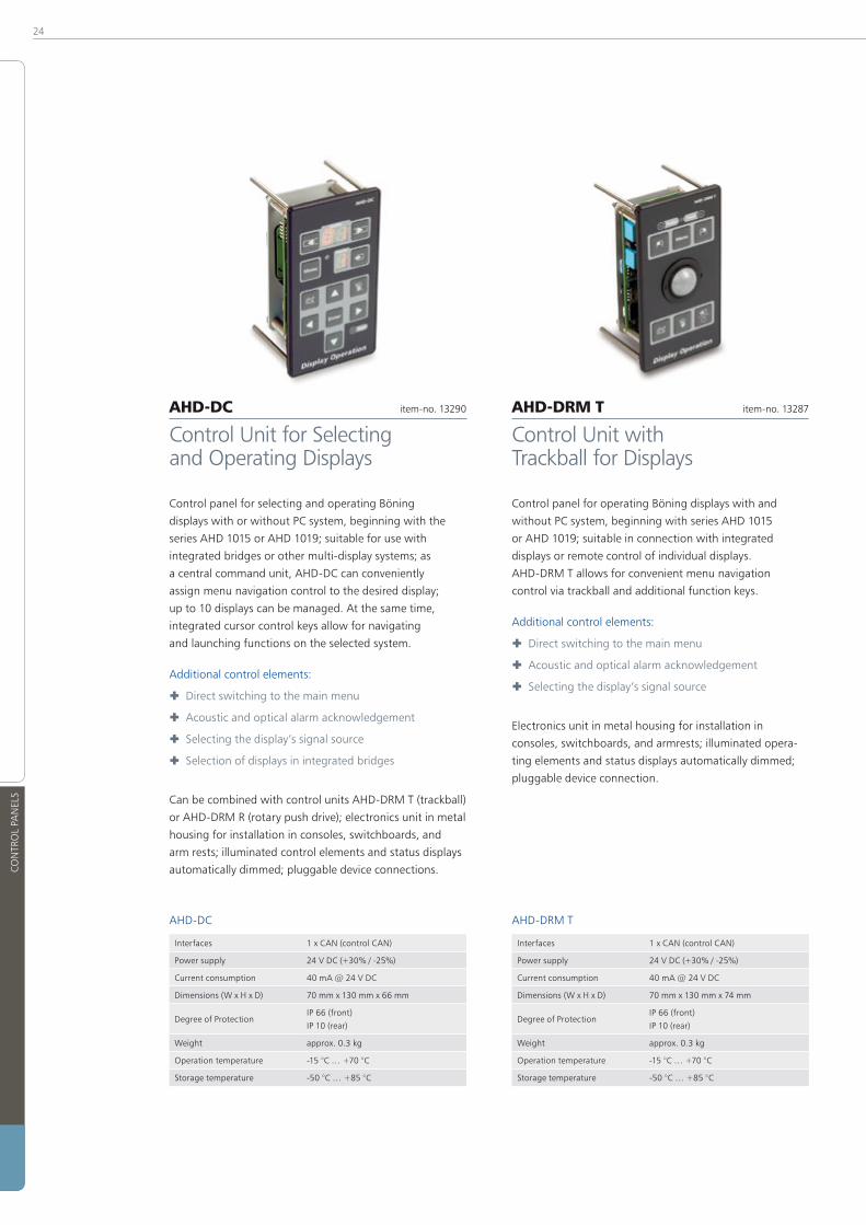
AHD-DC item-no� 13290
Control Unit for Selecting and Operating Displays
Control panel for selecting and operating Böning
displays with or without PC system, beginning with the
series AHD 1015 or AHD 1019; suitable for use with
integrated bridges or other multi-display systems; as
a central command unit, AHD-DC can conveniently
assign menu navigation control to the desired display;
up to 10 displays can be managed� At the same time,
integrated cursor control keys allow for navigating
and launching functions on the selected system�
Additional control elements:
® Direct switching to the main menu
® Acoustic and optical alarm acknowledgement
® Selecting the display’s signal source
® Selection of displays in integrated bridges
Can be combined with control units AHD-DRM T (trackball)
or AHD-DRM R (rotary push drive); electronics unit in metal
housing for installation in consoles, switchboards, and
arm rests; illuminated control elements and status displays
automatically dimmed; pluggable device connections�
AHD-DC
Interfaces 1 x CAN (control CAN)
Power supply 24 V DC (+30% / -25%)
Current consumption 40 mA @ 24 V DC
Dimensions (W x H x D) 70 mm x 130 mm x 66 mm
Degree of ProtectionIP 66 (front)
IP 10 (rear)
Weight approx� 0�3 kg
Operation temperature -15 °C … +70 °C
Storage temperature -50 °C … +85 °C
AHD-DRM T item-no� 13287
Control Unit with Trackball for Displays
Control panel for operating Böning displays with and
without PC system, beginning with series AHD 1015
or AHD 1019; suitable in connection with integrated
displays or remote control of individual displays�
AHD-DRM T allows for convenient menu navigation
control via trackball and additional function keys�
Additional control elements:
® Direct switching to the main menu
® Acoustic and optical alarm acknowledgement
® Selecting the display’s signal source
Electronics unit in metal housing for installation in
consoles, switchboards, and armrests; illuminated opera-
ting elements and status displays automatically dimmed;
pluggable device connection�
AHD-DRM T
Interfaces 1 x CAN (control CAN)
Power supply 24 V DC (+30% / -25%)
Current consumption 40 mA @ 24 V DC
Dimensions (W x H x D) 70 mm x 130 mm x 74 mm
Degree of ProtectionIP 66 (front)
IP 10 (rear)
Weight approx� 0�3 kg
Operation temperature -15 °C … +70 °C
Storage temperature -50 °C … +85 °C

25
CON
TRO
L PA
NEL
S
CONTROL PANELS
AHD-DRM R item-no� 13281
Control Unit with Rotary Push Drive for Displays
Control panel for operating Böning displays with and
without PC system, beginning with series AHD 1015 or
AHD 1019; suitable in connection with integrated displays
or remote control of individual displays� AHD-DRM R
allows for convenient menu navigation control via a
combined rotary push drive and additional function keys�
Additional control elements:
® Direct switching to the main menu
® Acoustic and optical alarm acknowledgement
® Selecting the display’s signal source
Electronics unit in metal housing for installation in
consoles, switchboards, and armrests; illuminated opera-
ting elements and status displays automatically dimmed;
pluggable device connection�
AHD-DRM R
Interfaces 1 x CAN (control CAN)
Power supply 24 V DC (+30% / -25%)
Current consumption 40 mA @ 24 V DC
Dimensions (W x H x D) 70 mm x 130 mm x 74 mm
Degree of ProtectionIP 66 (front)
IP 10 (rear)
Weight approx� 0�3 kg
Operation temperature -30 °C … +70 °C
Storage temperature -50 °C … +85 °C
AHD 650 R item-no� 10498
Remote Control Unit for 6�5" and 8�8" Displays
Remote control unit for 6�5” and 8�8” color
displays, series AHD 651 and AHD 880�
Compact unit for launching all display functions:
® Menu launching
® Switching pages
® and alarm acknowledgement
Electronics unit in metal housing for installation in
consoles, switchboards, and armrests; illuminated and
dimmed operating elements; pluggable device connection�
AHD 650 R
Interfaces1 x 8-Pin digital
(display remote connector)
Power supply 24 V DC (+30% / -25%)
Current consumption 10 mA @ 24 V DC
Dimensions (W x H x D) 40 mm x 130 mm x 41 mm
Degree of ProtectionIP 67 (front)
IP 55 (rear)
Weight approx� 0�2 kg
Operation temperature -30 °C … +70 °C
Storage temperature -50 °C … +85 °C
Approvals GL, LR

26
DA
TA S
TATI
ON
S, C
ON
TRO
LLER
S A
ND
SW
ITC
HIN
G U
NIT
S
Data Stations, Control and Switching Units
AHD-SAS 15 item-no� 11663
15 Channel Analog Data Capture
Data station with 15 input channels, suitable for capturing
current, power, and resistor sensors, changeover contacts,
thermo elements, (e� g� NiCrNi), pulse generators, and
other sensor types� The integrated processor system allows
for the autarkic processing and monitoring of analog
and binary signals� Here, pluggable input modules for
each channel allow for the highest degree of flexibility�
Direct alerting occurs via 4 potential free contacts, for
horn control and general alerting, among others�
Integrated interfaces for binary data stations of the
AHD-PS series capture up to 94 additional channels, if
necessary� In addition, a relay station AHD-R 101 with
15 changeover contacts can be directly controlled�
The standard version of AHD-SAS 15 is suitable
for carrier rail mounting (TS32/35), or as a special
version, for bulkhead installation (item-no� 10786)�
Inputs
15 x analog input,
sensor type modular pluggable:
4-20 mA, 0-5 V, 0-30 V, 0-45 V,
PT100, PT1000, NiCrNi,
frequency, switch etc�
3 x optocoupler input:
2 x serial (e�g� AHD-PS 15/30/47),
1 x alarm acknowledgment
(optical/acoustic)
Outputs
2 x optocoupler output serial
(e�g� for AHD-R 101)
4 x relay output (horn,
collective alarm 2 x configurable)
Interfaces2 x CAN (galvanically isolated),
1 x serial (RS-232)
Power supply 24 V DC (+30% / -25%)
Current consumption 520 mA @ 24 V DC
Dimensions (W x H x D) 210 mm x 125 mm x 84 mm
Degree of Protection IP 20
Weight approx� 0�7 kg
Operation temperature -30 °C … +70 °C
Storage temperature -50 °C … +85 °C
Approvals GL, LR, DNV, ABS

27
DA
TA S
TATI
ON
S, C
ON
TRO
LLER
S A
ND
SW
ITC
HIN
G U
NIT
S
DATA STATIONS, CONTROLLERS AND SWITCHING UNITS
AHD-PS 47 item-no� 10864
47 Channel Binary Data Capture
Binary data station for the decentralized capture of
47 sensors (contacts, transistor outputs, proximity
switches, etc�), serial data output to higher ranking
system components (AHD 882, AHD-SAS 15, or
AHD-DPU), inputs and outputs optically decoupled,
integrated status displays, 1 or 2 pin connection of
sensors possible, electronics unit in profile carrier
housing, suitable for carrier rail mounting (TS32/35)�
Inputs
47 x optocoupler input
(for changeover contacts,
octocoupler outputs,
1- or 2-pin connectible)
Outputs
3 x optocoupler output, serial:
dipolar, galvanically isolated,
open emitter (plus switched),
open collector (minus switched)
Power supply 24 V DC (+30% / -25%)
Current consumption 50 mA @ 24 V DC
Dimensions (W x H x D) 281 mm x 90 mm x 53 mm
Degree of Protection IP 10
Weight approx� 0�5 kg
Operation temperature -30 °C … +70 °C
Storage temperature -50 °C … +85 °C
Approvals GL, LR, DNV, CRS, ABS
AHD-PS 30 item-no� 10375
30 Channel Binary Data Capture
Similar to AHD-PS 47, but with 30 channels�
Inputs
30 x optocoupler input
(for changeover contacts,
octocoupler outputs,
1- or 2-pin connectible)
Current consumption 30 mA @ 24 V DC
Dimensions (W x H x D) 193 mm x 90 mm x 53 mm
Weight approx� 0�35 kg
AHD-PS 15 item-no� 10882
15 Channel Binary Data Capture
Similar to AHD-PS 47, but with 15 channels�
This device can be used as a parallel-serial converter
for reducing the cabling in spatially separate systems
(in conjunction with AHD-R 101)�
Inputs
15 x optocoupler input
(for changeover contacts,
octocoupler outputs,
1- or 2-pin connectible)
Current consumption 25 mA @ 24 V DC
Dimensions (W x H x D) 113 mm x 90 mm x 53 mm
Weight approx� 0�2 kg
28
DA
TA S
TATI
ON
S, C
ON
TRO
LLER
S A
ND
SW
ITC
HIN
G U
NIT
S
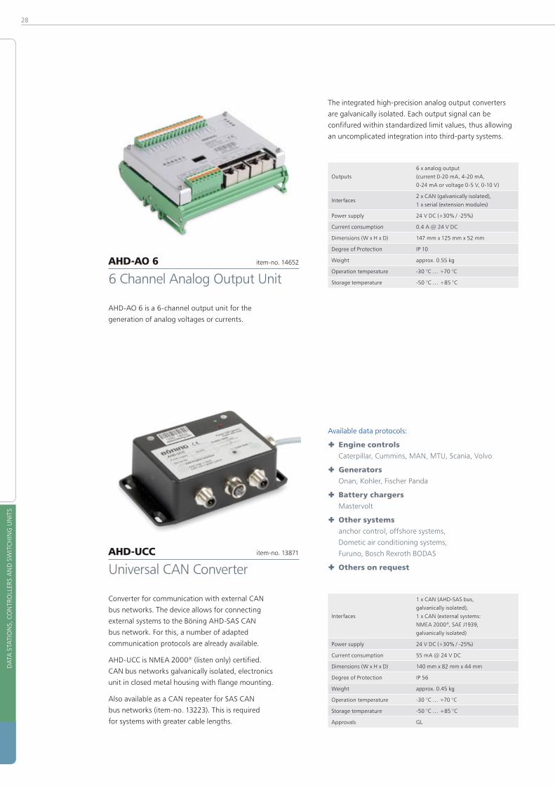
The integrated high-precision analog output converters
are galvanically isolated� Each output signal can be
confifured within standardized limit values, thus allowing
an uncomplicated integration into third-party systems�
Outputs
6 x analog output
(current 0-20 mA, 4-20 mA,
0-24 mA or voltage 0-5 V, 0-10 V)
Interfaces2 x CAN (galvanically isolated),
1 x serial (extension modules)
Power supply 24 V DC (+30% / -25%)
Current consumption 0�4 A @ 24 V DC
Dimensions (W x H x D) 147 mm x 125 mm x 52 mm
Degree of Protection IP 10
Weight approx� 0�55 kg
Operation temperature -30 °C … +70 °C
Storage temperature -50 °C … +85 °C
Available data protocols:
® Engine controls
Caterpillar, Cummins, MAN, MTU, Scania, Volvo
® Generators
Onan, Kohler, Fischer Panda
® Battery chargers
Mastervolt
® Other systems
anchor control, offshore systems,
Dometic air conditioning systems,
Furuno, Bosch Rexroth BODAS
® Others on request
Interfaces
1 x CAN (AHD-SAS bus,
galvanically isolated),
1 x CAN (external systems:
NMEA 2000®, SAE J1939,
galvanically isolated)
Power supply 24 V DC (+30% / -25%)
Current consumption 55 mA @ 24 V DC
Dimensions (W x H x D) 140 mm x 82 mm x 44 mm
Degree of Protection IP 56
Weight approx� 0�45 kg
Operation temperature -30 °C … +70 °C
Storage temperature -50 °C … +85 °C
Approvals GL
AHD-AO 6 item-no� 14652
6 Channel Analog Output Unit
AHD-AO 6 is a 6-channel output unit for the
generation of analog voltages or currents�
AHD-UCC item-no� 13871
Universal CAN Converter
Converter for communication with external CAN
bus networks� The device allows for connecting
external systems to the Böning AHD-SAS CAN
bus network� For this, a number of adapted
communication protocols are already available�
AHD-UCC is NMEA 2000® (listen only) certified�
CAN bus networks galvanically isolated, electronics
unit in closed metal housing with flange mounting�
Also available as a CAN repeater for SAS CAN
bus networks (item-no� 13223)� This is required
for systems with greater cable lengths�

29
DA
TA S
TATI
ON
S, C
ON
TRO
LLER
S A
ND
SW
ITC
HIN
G U
NIT
S
DATA STATIONS, CONTROL AND SWITCHING UNITS
An integrated logging function records all events� Thus,
any status messages or the watch standby status can be
logged� The last 16,000 can be viewed at any time�
Various ports (including LAN) support its inte-
gration into the ship’s existing infrastructure�
AHD-DPU 9 is NMEA 2000® certified�
Inputs
4 x optocoupler input
(alarm acknowledgment,
special function optional)
Outputs
5 x relay output
(galvanically isolated,
2 x contact 2-pin,
3 x contact 1-pin)
Combined in/out
28 x optocoupler channel
(bidirectional),
can be used as input or output,
for serial data exchange
or switch function
Interfaces
6 x CAN (galvanically isolated,
termination and
address switchable),
LAN (RL45, 10/100 Mbit),
2 x serial (RS-232/RS-485/RS-422),
1 serial (RS-232/485)
switchable, bus termination
switchable
Power supply 24 V DC (+30% / -25%)
Current consumption 170 mA @ 24 V DC
Dimensions (W x H x D) 188 mm x 126 mm x 63 mm
Degree of Protection IP 20
Weight approx� 0�7 kg
Operation temperature -30 °C … +70 °C
Storage temperature -50 °C … +85 °C
Approvals GL
AHD-DPU 9 item-no� 15129
Data Processing Unit
Powerful logic unit for integrated ship alarm,
monitoring, and control systems� It can capture and
process all data accruing in the board system� This
includes the evaluation of all integrated sensors
captured via analog or binary data stations�
Every measuring point is monitored under consi-
deration of various parameters and can be alerted,
if thresholds are exceeded� All data are available
in the Böning SAS bus and can be displayed with
matching Böning displays (e� g� AHD 1215)�
AHD-DPU 9 supports mathematic and
logical operations (SPS functions)�

30
DA
TA S
TATI
ON
S, C
ON
TRO
LLER
S A
ND
SW
ITC
HIN
G U
NIT
S
Alternate versions:
� AHD-R 101 (AHD 882 Hold/Classifiable) saves relay state after data loss
(item-no� 14753)
� AHD-R 101 (AHD 882 DoubleSerial/ Redundant) for redundant systems (item-no� 14757)
� AHD-R 101 (CustomConfig) customer specific configuration (item-no� 14757)
� AHD-R 101 (SAS-15 Hold/Classifiable) like item no� 14753, but for
AHD-SAS 15 (item-no� 15315)
� AHD-R 101 (SAS-15 NoHold) like item no� 14754, but for
AHD-SAS 15 (item-no� 15463)
Inputs2 x optocoupler input
(serial 1, serial 2)
Outputs
15 x relay output
(changeover contact,
galvanically isolated),
230 V AC, 3 A or 30 V DC,
2 A (channel 15 = error message)
Power supply 24 V DC (+30% / -25%)
Current consumption 320 mA @ 24 V DC
Dimensions (W x H x D) 147 mm x 112 mm 55 mm
Degree of Protection IP 10
Weight approx� 0�55 kg
Operation temperature -30 °C … +70 °C
Storage temperature -50 °C … +85 °C
Approvals GL, LR, DNV
AHD-R 101 item-no� 14754
15 Channel Relay Station
Relay output station with 15 changeover contacts,
adapted for the serial transmission of data stations or
central control units, such as AHD-DPU 9 or AHD 882 (for
controlling AHD-SAS 15, see item no� 15315 or 15463)�
® Control of pumps, engines, pilot lamps,
room lighting, or other actuators
® Transmission of status messages to external
systems (potential free changeover contacts)
® Use as a serial-parallel converter for reducing
the cabling in spatially separated systems
(in conjunction with AHD-PS 15)
® Integrated LEDs as status indicators

31
DA
TA S
TATI
ON
S, C
ON
TRO
LLER
S A
ND
SW
ITC
HIN
G U
NIT
S
DATA STATIONS, CONTROL AND SWITCHING UNITS
Versions with alternative ports:
� AHD-UIC with 1 x RS-485, 1 x RS-422
(item no� 13790);
� AHD-UIC with 2 x RS-422
(item no� 13800)
Versions with preconfigured protocols for:
® Main engines
(MAN, MTU, Volvo, ComAp, SymAp),
® Battery chargers
(Mastervolt, Victron Energy [DC], Deif [AC])
® Fire monitoring
(Kentech, Consillium)
® Lighting control (Cantalupi)
® Stabilizers (ABT, Sleipner, Trac),
® Generators (CAT)
® Miscellaneous (Maxwell)
Interfaces
2 x RS-485/RS-422 (isolated),
1 x CAN, 1 x RS-232,
data rates up to 38,400 baud
Power supply 24 V DC (+30% / -25%)
Current consumption 85 mA @ 24 V DC
Dimensions (W x H x D) 135 mm x 130 mm x 55 mm
Degree of Protection IP 20
Weight approx� 0�35 kg
Operation temperature -30 °C … +70 °C
Storage temperature -50 °C … +85 °C
Approvals GL, LR
AHD-UIC item-no� 11334
Serial CAN Protocol Converter
(Basic version, 2 x RS-485 without configuration)
Universal interface converter for communicating with
external ports such as RS-485/RS-422 or RS-232�
This device allows external systems to be connected
to the Böning AHD-SAS CAN bus network�
A number of adapted communication protocols
are already available for this� Other system specific
protocols can be configured on request�
® Reactionless capture and conversion
of analog and binary data
® Cyclical processing of up to
100 Modbus data packets
® Configurable data capture
® Redundant system available in combination
with two devices (master/slave)

32
DA
TA S
TATI
ON
S, C
ON
TRO
LLER
S A
ND
SW
ITC
HIN
G U
NIT
S
Each circuit breaker is equipped with integrated
emergency operation, allowing for the independent
addition or deletion of each user, even in case of error�
Tripping characteristic type B�
Alternative version:
� Tripping characteristic type C (item-no� 14708)
InputsCentral feed: 2-pin 125 A,
6 switch inputs (direct control)
Outputs
6 circuit breaker outputs,
16 A ea�
or 4 circuit breaker outputs,
16 A ea� and
1 circuit breaker output, 28 A
or 2 circuit breaker outputs,
28 A ea� and
2 circuit breaker outputs, 16 A ea�
Fuse
max� release current switchable
6�3, 10, 16 or 28 A (dual channel),
available with tripping
characteristics type B or C, current
monitoring starting at 50 mA,
release current configurable
InterfacesCAN bus (Böning bus),
NMEA 2000® on request
Power supply 24 V DC (+30% / -25%)
Current consumption 220 mA @ 24 V DC
Dimensions (W x H x D) 219 mm x 125 mm x 70 mm
Degree of Protection IP 20
Weight approx� 1�6 kg
Operation temperature -30 °C … +70 °C
Storage temperature -50 °C … +85 °C
Within an integrated bridge system, devices are mostly
operated with the control units AHD-DC, AHD-DC R,
AHD-DRM R, or AHD-DRM T� The commands thus issued
are sent to the Böning PCs via a common control bus
and via the AHD-CUC also to the external systems�
Thus, all participating PC systems can be conveniently
controlled via a common user interface� Depending
on the configuration, the command transfer can also
occur based on the selected video data source�
Interfaces
1 x CAN
(AHD-SAS, control CAN bus),
1 x USB 2�0
(supports Windows XP®,
Windows 7® support in preparation)
Power supply 24 V DC (+30% / -25%)
Current consumption 30 mA @ 24 V DC
Dimensions (W x H x D) 93 mm x 125 mm x 89 mm
Degree of Protection IP 20
Weight approx� 0�25 kg
Operation temperature -30 °C … +70 °C
Storage temperature -30 °C … +85 °C
AHD-RB 6 item-no� 14205
Electronic Circuit Breaker
Electronic remote controlled circuit breaker (ECB)
for securing up to six independent users�
All load circuits are switched in a dipolar manner� The
maximum connection load is 16 or 28 Amperes at
an on-board voltage of 24 V� The unit is controlled
remotely via the existing system bus or separate control
inputs which also allow “standalone” operation�
When used for lighting control, the outputs can
be regulated continuously (dimmer function)�
The tripping threshold can be set freely for each
channel� Short circuits and other error states are
detected and reported to the central alarm unit�
AHD-CUC item-no� 13291
CAN-USB Converter
CAN-USB control for transmitting mouse and
keyboard commands to external systems�
Normally, external PC systems whose visual data output
is meant to be integrated with the Böning system (e� g�
navigation systems) are connected via this device�

33
DA
TA S
TATI
ON
S, C
ON
TRO
LLER
S A
ND
SW
ITC
HIN
G U
NIT
S
DATA STATIONS, CONTROLLERS AND SWITCHING UNITS
The integrated logging function saves up to 10,000
events� These can be accessed with a service
computer via the integrated RS-232 port�
As a special function, a log printer can be controlled�
Inputs
18 x optocoupler input
(static or serial),
2 x alarm acknowledgment
(optical and acoustic)
Outputs
16 x transistor output
short-circuit proof,
static or serial (open-collector)
Interfaces
2 x CAN (galvanically isolated),
1 x serial (RS-232),
7 x relay outputs (5 x group alarm,
1 x collective alarm, 1 x horn relay)
Power supply 24 V DC (+30% / -25%)
Current consumption 125 mA @ 24 V DC
Dimensions (W x H x D) 216 mm x 125 mm x 71 mm
Degree of Protection IP 10
Weight approx� 0�6 kg
Operation temperature -30 °C … +70 °C
Storage temperature -50 °C … +85 °C
Approvals GL, LR, DNV
AHD 882 item-no� 10390
Central Unit
Up to 18 serial input channels gather information from
external data stations (e� g� AHD-PS 15, 30, or 47) or
alternative data sources� In addition to the binary infor-
mation, analog data from the SAS bus (CAN) can also be
processed� A total of 846 processing channels are possible�
16 output channels are available for transmitting
message data or control groups� These can control
e� g� binary alarm panels, such as AHD 406-2, or
relay units (e� g� AHD-R 101), directly and thus
trigger switch or control processes�
All processed data can be distributed or grouped
as desired with a powerful configuration tool�

34
REM
OTE
MO
NIT
ORI
NG
AN
D F
AU
LT D
ETEC
TIO
N
Desktop-PC | Notebook | Tablet | Smartphone
AHD 1219
CAN-Bus
CAN-Bus
BNC
AHD-DPU 9
AHD-VDCU
AHD-WNA
Ethernet-Switch
(Optional)

35
REM
OTE
MO
NIT
ORI
NG
AN
D F
AU
LT D
ETEC
TIO
N
REMOTE MONITORING AND FAULT DETECTION
Remote Monitoring and Fault Detection
AHD-WNA
Internet Access to Böning Systems
AHD-WNA allows for viewing the vessel’s current
data and sending commands to the ship system
from any location with Internet access�
Using an Ethernet port, AHD-WNA is integrated into the
ship’s bus system via a Panel PC AHD 1215 F, AHD 1215 G,
AHD 1219 F, AHD 1219 G, or Data Station AHD-DPU 9;
an additional port establishes the connection to the
operator provided Internet access (data rate 3G or higher)�
The user accesses AHD-WNA with a web browser, which
provides the ship’s data visualization and controls, known
from the ship’s Böning displays, via remote access� This
ensures the customary fast and secure operation�
To ensure the vessel’s safe operation, safety
relevant functions, such as starting and stop-
ping the engine, cannot be opened�
Access to AHD-WNA is password protected� AHD-WNA
secures data traffic with the user by means of the
known to be secure AES256 encryption protocol�
Already existing Böning systems can
be retrofitted with AHD-WNA�
Router
Home Network
Router

36
REM
OTE
MO
NIT
ORI
NG
AN
D F
AU
LT D
ETEC
TIO
N
AHD-WNL
Mobile iPad® Conectivity and Logging
AHD-WNL (Web and Log) integrates the iPad®, iPhone®,
iPod®, and other clients seamlessly into the ship’s Böning
monitoring and control system� The user can access the
ship’s data and – with the corresponding rights – controls
at any time in the WLAN board network� The visualization
on the clients matches the visualization on the ship’s
displays, thus ensuring familiar, safe operation�
AHD-WNL logs the Böning system’s data according to
configured channels and exports them in flexible file
formats� AHD-WNL consists of a PC with the AHD-WNL
server installed there� A 12xx-series panel PC or data
station AHD-DPU 9 connect AHD-WNL to the ship’s Böning
system� With it, all data can be visualized� The connection
to the ship’s WLAN is established via a user provided
WLAN router or an already installed WLAN on board�
User management data, visualization of supported devices,
and logging are stored on the AHD-WNL server� Configu-
ration and logging data can simply be accessed over a web
interface that is compatible with most common browsers�
In the user management, the extent of each user’s access
to the vessel’s data and controls is set up during delivery
and according to the customer’s wishes� Thus, e� g�
guests may be permitted to know the ship’s location and
cruising speed or switch the cabin lighting on or off�
Standard pages that can be matched to the individual
presentation on the ship displays with the most
important functions are available for the visualization
on clients� On request, pages matching the individual
presentation on the ship displays can be created� Existing
Böning systems can be retrofitted with AHD-WNL�
AHD-WNL can also be accessed from the Internet�
Only under certain conditions AHD-WNL is intended for
use in commercial shipping� Supported clients: iPad®,
generation 2 and later; iPhone®, generation 4 and later;
iPod® Touch, generation 4 and later; PCs and laptops
with Microsoft Windows®, Windows XP SP3 and later�
Supported clients
iPad®, generation 2 and later; iPhone®,
generation 4 and later; iPod® Touch,
generation 4 and later; PCs and
laptops with Microsoft Windows®,
Windows XP SP2 and later
Power supply 9 ��� 36 V DC
Power consumption 60 W
Battery supply Integrated, sufficient for 10 minutes
Degree of Protection IP 20
Operation temperature -40 °C … +70 °C
Storage temperature -40 °C … +80 °C
AHD 1219
CAN-BusBNC
Eth
ern
et
AHD-DPU 9
AHD-VDCUVideo-IP-Konverter
AHD-WNL
WLAN-Router

37
REM
OTE
MO
NIT
ORI
NG
AN
D F
AU
LT D
ETEC
TIO
N
REMOTE MONITORING AND FAULT DETECTION
AHD-IAMCS
Visualizing Software for AHD-WNL
In conjunction with AHD-WNL on the board WLAN,
AHD-IAMCS (Integrated Alarm, Monitoring and Control
system), available at the Apple App Store for free� It
allows access to the ship’s data and controls with the
clients iPad®, iPhone® and iPod®� The visualization,
matched to the presentation on the ship displays, ensures
operational safety, thus making AHD-IAMCS a fully valid
component of the Böning monitoring and control system�
The ship’s data are displayed and access to the controls is
enabled according to the user rights stored in AHD-WNL�
The ship specific configuration data for the graphic visuali-
zation are transferred by AHD-WNL to the clients one time
during logon� The ship’s data are continuously transferred
to the client, allowing real-time and safe control and
management everywhere and at any time on board�
Many standard pages are available for the most
common data and control functions, e� g� tanks, bilge
pump monitoring and control, and many more� At
the customer’s request, pages matched to the specific
presentation on the ship’s displays can be created�
For Apple iOS®, Version 5 and later
AHD-Charting
Graphical Presentation of AHD-WNL Logging Data
AHD-Charting complements the AHD-WNL installed on
board� AHD-WNL logs the data of ship system channels set
up during the system configuration, allowing their export
to Microsoft Excel® and viewing on the vessel’s displays�
AHD-Charting expands AHD-WNL’s functionality with the
easily comprehensible graphic presentation of the logged
data� AHD-Charting can be downloaded from AHD-WNL’s
administration pages and the manufacturer’s website�
AHD-Charting is suitable for PCs and laptops with
Microsoft Windows XP® or later� Apart from an Ethernet
cable, no other hardware is required� The logged data
are available in AHD-Charting after completing the
software’s simple installation procedure and establishing
the connection to AHD-WNL� No additional configuration
is required for AHD-WNL or the vessel’s Böning system�
In the graphic presentation, the user can view
individual values, move the displayed curve,
enlarge value ranges by zooming, and export
their data in Microsoft-Excel®’s xls-format�
For Windows® PCs with Windows XP® SP3 and newer�

38
REM
OTE
MO
NIT
ORI
NG
AN
D F
AU
LT D
ETEC
TIO
N
GSM-Kit
Alarm and Messaging Unit
The GSM-Kit (Alarm Messenger Unit) is an additional
alert system with quad band GSM modem and
suitable mobile telephone antenna� During an alarm,
the system sends a message to a previously entered
telephone number (e� g� the owner’s or captain’s
cell phone) with detailed alarm information�
It is connected to a monitor with integrated PC (such as
AHD 1219) in the Böning alarm system via a serial cable�
The message is sent via short messaging service (SMS)�
All commercially available cell phones are supported�
A special app for the cell phone is not necessary�
Before using the system, the user only needs to
enter the receiving party’s telephone number and
the SIM card’s PIN and then activate the system�
This ensures a maximum degree of on-board safety
when the ship is anchored in the harbor or only watch
keepers are on board (GSM reception required)�
A SIM card is not included and must
be provided by the customer�

39
INTE
GRA
TED
ALA
RM, M
ON
ITO
RIN
G A
ND
CO
NTR
OL
SYST
EM
INTEGRATED ALARM, MONITORING AND CONTROL SYSTEM
AHD-SW I item-no� 10873
Spill Warning Gauge
Warning device for acoustic and optical alerting
impending fuel spills during fueling� AHD-SW is an active
contribution to environmental protection� Fuel tank
spills are avoided by a clearly audible warning signal�
Continuous fuel level display in conjunction with
Böning ship alarm systems AHD-SAS 15�
AHD-SW I for monitoring a single tank:
® Integrated button for switching off
the acoustic signal
® Luminosity automatically adjusted
to ambient brightness
® Several warning gauges per tank
can be combined
® Weather resistant, robust design
for outdoor use
Alternate version for 2 tanks (stb and bb) available:
� AHD-SW II (item-no� 10874)
Inputs1 x optocoupler input
(Alarm acknowledgment)
Outputs 1 x relay output (Horn)
Interfaces3 x optocoupler input
(serial data AHD-SAS 15)
Power supply 24 V DC (+30% / -25%)
Current consumption 20 mA
Dimensions (∅ x T) 100 mm x 39 mm
Degree of ProtectionIP 67 (front)
IP 31 (rear)
Weight approx� 0�4 kg
Operation temperature -25 °C … +65 °C
Storage temperature -50 °C … +85 °C

40
INTE
GRA
TED
ALA
RM, M
ON
ITO
RIN
G A
ND
CO
NTR
OL
SYST
EM
AHD-S 201 item-no� on request
Hydrostatic Level Transmitter
The Hydrostatic Level Transmitter AHD-S 201 was
developed for capturing fuel levels in service and
product storage tanks and based on its Germanic
Lloyd certification, it is predestined for applications
in shipbuilding and offshore use� Its operating range
encompasses level readings in ballast tanks, tanks with
fuel and oils, service and waste water tanks, etc� as
well as a vessel’s position and draught measurement�
PE4000WE item-no� 12520
Inclination Angle Sensor
By means of inclination sensor PE 4000 WE, the trim or list
inclination of a ship can be recorded (one sensor required
per axis) in order to allow inclination depending content
calculation corrections e� g� tank content measurements�
The sensor is delivered in a robust aluminium housing in
two versions (with plug connector or cable connection)�
The AHD-S 201’s basis is a specifically optimized
capacitive-ceramic sensor element which distinguishes
itself through its high overload capacity and resistance
to chemicals� Its high temperature operating range (up
to 125 °C) and use in the areas with potentially explosive
atmospheres (optional) allow for the pressure readings for
a wide range of fluids under extreme operating conditions�
Standard version:
® Nominal pressures = 0…40 cm H2O or 0…200 cm H2O
® Precision = 0�25 % FSO (according to IEC 60770)
® Customer specific versions on request
Outputs 4 ��� 20 mA @ Ub=10 ��� 32 V DC
Power supply 24 V DC (+30% / -25%)
Current consumption 21 mA
Dimensions (∅ x L) 39�5 mm x 132�5 mm
Degree of Protection IP 68
Weight approx� 0�65 kg (without cable)
Operation temperature-25 °C ��� +125 °C
-25 °C ��� +80 °C (cable)
Storage temperature-40 °C ��� +125 °C
-40 °C ��� +80 °C (cable)
Approvals GL
® Further features of the sensor are:
® Oil-damped single-axis pendulum system
® Inductive measurement principle
® Angle max� +/- 45°
® Angle accuracy < +/- 0�5 %�
Outputs 4 ��� 20 mA
Power supply 18 ��� 33 V DC
Degree of Protection IP 65
Weight approx� 1�0 kg
Further available inclination angle sensor:
AHD-TCS INCL item-no� 11944
Inclination Angle Sensor for Trim Tabs Control System AHD-TCS
Further availbale: Description and
specifications see page 70�

41
INTE
GRA
TED
ALA
RM, M
ON
ITO
RIN
G A
ND
CO
NTR
OL
SYST
EM
INTEGRATED ALARM, MONITORING AND CONTROL SYSTEM
DeviceNet item-no� on request
CAN Terminal and CAN Bus Accessories
Accessory for CAN bus interconnection of Böning devices�
CAN terminal - CAN Bus Interface Module
It includes a CAN bus connection feedthrough socket over
a 6-pin terminal strip (2 x CAN-H / CAN-L / CAN-Shield)
and/or DeviceNet connectors (1 x male / 1 x female)�
In addition, a switchable terminating resistor is integrated�
The module housing is intended for rail mounting�
DeviceNet Drop Cable, cable endings with 5-pole plug connector (plug / socket)
® Length 0�3 m / 2 m / 10 m / 25 m / 55 m
® T-piece for DeviceNet modules, cable endings
with 5-pole plug connector (plug / socket)
® Terminating resistor provided with 5-pole
plug connector (plug / socket)
Accessory for serial connections (not illustrated)
� Serial data cable, l = 15�0 m, cable endings with
4-pole plug connector Lumberg M12 (socket / socket)
� Length: 15 m / 20 m / 25 m

42
INTE
GRA
TED
ALA
RM, M
ON
ITO
RIN
G A
ND
CO
NTR
OL
SYST
EM
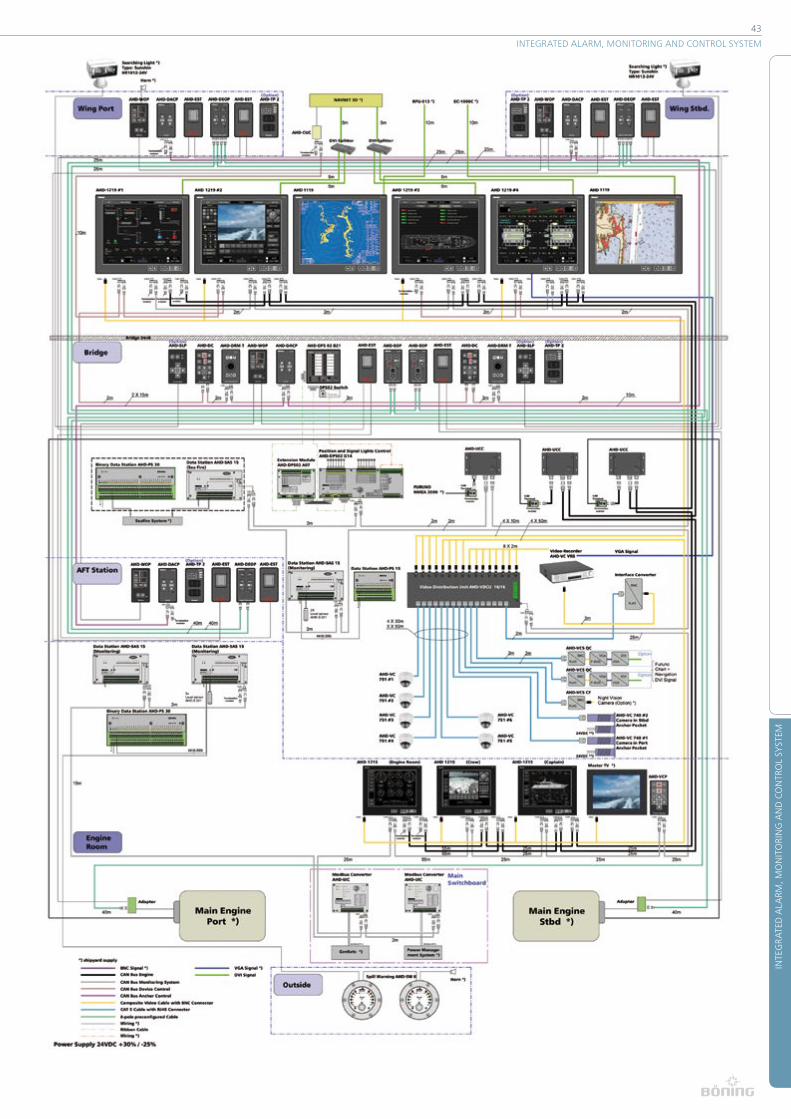
BIBS – Integrated Bridge System
The BIBS (Böning Integrated Bridge System) serves as
the central control and display platform, where all data
present in the system are processed and visualized�
For this purpose, 19” AHD 1219 color displays with integ-
rated panel PC (panel computer), controlled by an innova-
tive operating concept, are installed in the bridge console�
Over a control CAN bus, every AHD 1219 color display (up
to 8 displays) can be selected and operated centrally from
the Control Unit AHD-DC� Furthermore, each AHD-DC
unit is assigned a Control Unit AHD-DRM T, with which
the navigation of system menus and the operation of
control elements in the graphic visualization can be
comfortably executed via trackball� Moreover, these units
can also be integrated into e�g� the pilot seat’s armrest�
All connected system’s data are graphically rendered,
integrated into ship graphics and master plans, and
visualized individually on the color displays�
To meet the classification societies’ equipment regulations,
the BIBS Integrated Bridge System is completed with two
19” color monitors AHD 1119� These monitors have been
tested and approved for displaying radar and ECDIS sea
charts by classification societies and the Federal Maritime
and Hydrographic Agency (BSH)� One monitor is integrated
for each, radar and ECDIS sea charts� It is directly
controlled by the respective external system (e� g� Furuno)�
The following functions are displayed and controlled:
® Navigation with sea charts and radar
(over DVI port with connection to a Furuno control
system via CAN/USB Converter AHD-CUC)
® Data display for backboard and
starboard main engines (over a separate engine CAN bus for each engine)
® Connection to the Böning ship alarm system
® Tank gauge system
with continuous tank contents measuring
via hydrostatic level transmitters
® Door monitoring system
for all relevant doors, hatches, and flaps; in part,
with alerting based on the vessel’s cruising speed
® Integration of CCTV camera control (video signal via the displays’ video input)
® Display and control of
navigation and signal lanterns
® Visualization of generator data and power management system
by external manufacturers
® Monitoring of circuit breakers with remote controlled reactivation
® Connection to the fire alarm system
® Conning page with easy to view display of all relevant information
as well as depth sounding indicator and presentation
of the vessel’s roll and pitch movements�
® Visualization of anchor winch data
with chain counter and alarm function
® Control of pumps and valves
43
INTE
GRA
TED
ALA
RM, M
ON
ITO
RIN
G A
ND
CO
NTR
OL
SYST
EM
INTEGRATED ALARM, MONITORING AND CONTROL SYSTEM

44
OPE
RATI
ON
PA
NEL
S
Operation PanelsThe increase in on-board automation also leads
to an increase in data that must captured� On the
bridge, it is generally visualized by a multitude of
different instruments by diverse manufacturers�
The captain must constantly adjust to the manifold
operating concepts of these instruments�
In our view, harmonizing the vessel’s operation,
especially on the bridge, is an important task that
can contribute to operational safety and comfort�
This is why in recent years, we have developed nume-
rous control units with a unified design and under
consideration of the latest ergonomic aspects�
All devices feature automatic dimming as well
as a unified, glare-free design, allowing for
reliable operation when cruising at night�
Our team is happy to advise you on control units,
switch panels, panel PCs, or bridge modules�

45
OPE
RATI
ON
PA
NEL
S
OPERATION PANELS
AHD-WAOP item-no� 13146
Watch Alarm Panel (BNWAS)
The AHD-WAOP watch alarm panel “Bridge
Navigational Watch Alarm System” (BNWAS)
meets the requirements of IEC62616-1�
It ensures the bridge crew’s watch standby readi-
ness� All watch duty times can be changed after
entering a user code� The selected time elapses and
has to be acknowledged before running out�
If no acknowledgement is received, the following alarms are raised:
® First the display of the AHD-WAOP and
the mushroom button start blinking,
® Followed by switching on the internal
buzzer as well as relay output "Stage 1"
® Followed by switching on the relay output "Stage2"
® Followed by switching on the rely output "Stage 3"
AHD-WAOP K item-no� 13224
Watch Keeper Panel (Dead Man System)
Watch keeper panel for ships required to carry such equip-
ment, meets the requirements of a “Bridge Navigational
Watch Alarm System” (BNWAS) according to IEC62616-1,
and ensures the watch keeper’s watch standby readiness�
Equipped with a lit mushroom button for easy cyclical
activation� Here, intervals of a duration of up to 12
minutes can be set� If the mushroom button is pressed
and held for 5 seconds, an emergency alarm is raised�
All system settings such as e� g� time or password can
be altered with the system keys and are visualized
on the display� Up to 4 acknowledge-authorized
end devices can be directly connected for an easy
acknowledgement at different locations on the bridge
(freely enlargable with multiples)� If the external
devices are designed accordingly, simultaneous
blinking of internal and external buttons is possible�
Inputs6 x input, potential-free (4 x for ext�
acknowledgement, ext� start, ext� stop)
Outputs4 x relay output (buzzer, alarm,
general alarm, error)
Interfaces 1 x RS-485 (connection to VDR)
Power supply 24 V DC (+30% / -25%)
Current consumption 0�25 A @ 24 V DC
Dimensions (W x H x D) 70 mm x 130 mm x 107 mm
Degree of ProtectionIP 44 (front)
IP 20 (rear)
Weight approx� 0�4 kg
Operation temperature -15 °C … +70 °C
Storage temperature -50 °C … +85 °C
Approvals GL, LR, MCA (MED in preparation)
All watch duty times can be changed after entering a user
code� A 3-stage pre-alarm is raised prior to triggering the
general alarm� Equipped with a key switch� Removing the
key activates the system for the duration of the watch duty�
For this, time intervals of up to 30 minutes can be set�
Equipped with integrated display and operating keys
for specifying all system settings (such as e�g� time or
password), integrated emergency call function, inputs for
up to 4 acknowledge-authorized end devices, outputs
for horn, pre-alarm, general alarm, and system errors,
automatic dimming for all operating and lighting elements�
Technical specifications see AHD-WAOP (above)

46
OPE
RATI
ON
PA
NEL
S
AHD-WAOP S item-no� 14712
Signalling Device
Additional signalling device to the AHD-WAOP
for installation on the bridge�
Functions:
® Reset
® Emergency call
® Buzzer
® Blinking
® Dim function for glare-free operation�
AHD-WAOP S AP-A item-no� 15052
Aditional Device for Cabins
Additional devioce to the AHD-WAOP S for installation in
messes and cabins� With blinking and signalling function
as well as optical and acoustical alarm annunciator�
Available in two versions:
� Installation in consoles
� Wall installation
AHD-WAOP S AP-K item-no� 14716
Additional Device for Workspace
Additional device to the AHD-WAOP for instal-
lation at strategic ponts in the workspace�
Functions:
® Reset
® Optical (blinking)
and acoustical (buzzer) alarm
Available in two versions:
� Installation in consoles
� Wall installation
AHD-WAOP S MDA item-no� 15623
Motion Detector
With automatic reeset function in case of motion
detection, for installation on the bridge (not
approved by all classification societies)�

47
OPE
RATI
ON
PA
NEL
S
OPERATION PANELS
AHD-GAP F item-no� 14002
General Alarm Unit with Fire Alarm Function
AHD-GAP F is used to control the acoustic and optical
ship alarm devices in emergency situations� In addition
to manual signal activation, all required signals, such as
“Abandon Ship”, “General Alarm”, and “Fire Alarm” are
pre-programmed and can be accessed directly; signal
and pause intervals can be preselected in stages; external
inputs for triggering general or fire alarm as well as
pause control; key lock against unintended activation,
secure power supply via main and emergency feed;
Weather proof, robust design, suitable for use on brides
or outdoor use, automatic dimming of the operation and
display elements�
AHD-GAP F
Inputs3 x control input for fire alarm,
general alarm and signal pause
Outputs5 x relay output (system
error, 4 x signal control)
Power supply24 V DC (+30% / -25%)
2 inputs
Current consumption 0�1 A @ 24 V DC
Dimensions (W x H x D) 70 mm x 130 mm x 65 mm
Degree of ProtectionIP 66 (front)
IP 20 (rear)
Weight approx� 0�3 kg
Operation temperature -30 °C … +70 °C
Storage temperature -50 °C … +85 °C
Approvals GL, LR
AHD-TP 2 item-no� 12879
Operating Panel for Thrusters
The thruster panel AHD-TP 2 allows for comfortable
and individual control of two hydraulically and/or VFD
(electrically) operated ABT thrusters� Compact structure,
designed for installation in helms, panels, switch boards
or switch cabinets; water tight design for outdoor use;
suitable for use on bridges due to dimming of the indicator
lights; integrated monitoring with acoustic signal device;
Single-axis joystick with no-contacting hall operating
principle, version as 2-channel control with automatic
return in center position; alternatively, available
with friction hold function (upon request)�
Also available with digital joysticks: AHD-TP 2 D
AHD-TP 2
Inputs 3 x signal (error feedback)
Outputs2 x control voltage analog
0�5-5 V, 2 x signal (start, stop)
Power supply 24 V DC (+30% / -25%)
Current consumption 0�1 A @ 24 V DC
Dimensions (W x H x D) 70 mm x 130 mm x 65 mm
Degree of ProtectionIP 66 (front)
IP 20 (rear)
Weight approx� 0�3 kg
Operation temperature -30 °C … +70 °C
Storage temperature -50 °C … +85 °C

48
OPE
RATI
ON
PA
NEL
S
AHD-SLP item-no� 10691
Searchlight Control
Operating panel for controlling a searchlight in the uniform
design of the yacht device series� The functional scope
encompasses the searchlight’s orientation in any direction�
The positional change can be selected in 2 stages�
Button for switching the lamp on and off; additional
function key for setting the light signals manually; up to
4 control units can be networked in a parallel manner�
Compact module for installation in consoles or switch
cabinets; suitable for indoor and outdoor applica-
tions; suitable for use on bridges due to automatic
dimming of all operation and lighting elements;
standard version for controlling our searchlight
AHD-SL (Sanshin HR1012 with 12 V control inputs);
Alternatively, available with 24 V control outputs for cont-
rolling other searchlights: AHD-SLP 24 V (item-no� 14769)
AHD-SLP
Outputs1 x transistor, short-circuit proof
(lamp, vertical tilt, horizontal pan)
Interfaces1x optocoupler
(bus for additional operation units)
Power supply24 V DC (+30% / -25%)
2 inputs
Current consumption 30 mA @ 24 V DC
Dimensions (W x H x D) 70 mm x 130 mm x 66 mm
Degree of ProtectionIP 66 (front)
IP 20 (rear)
Weight approx� 0�15 kg
Operation temperature -30 °C … +70 °C
Storage temperature -50 °C … +85 °C
AHD-SL item-no� 10756
Searchlight Type HR1012, Remote Controllable
Searchlight HR1012 (Sanshin) for illumination during
nighttime maneuvering operations or as signal
devices; equipped with two powerful halogen lamps
(55 W each, with reflector inserts) and remote
controllable pan and tilt function; 360° horizontal
lamp positioning (endless rotation) and 26°; max�
reach 500 m at a luminosity of 160,000 cd;
Version in seawater resistant aluminum die-cast housing;
protection class IP 56 (front) for indoor and outdoor use
AHD-SL
Inputs3 x control input
(lamp, vertical tilt, horizontal pan)
Current consumption 5 A @ 24 V DC
Dimensions (W x H x D) 230 mm x 200 mm x 210 mm
Degree of Protection IP 56
Weight approx� 3�25 kg
Operation temperature -10 °C … +70 °C
Storage temperature -50 °C … +85 °C
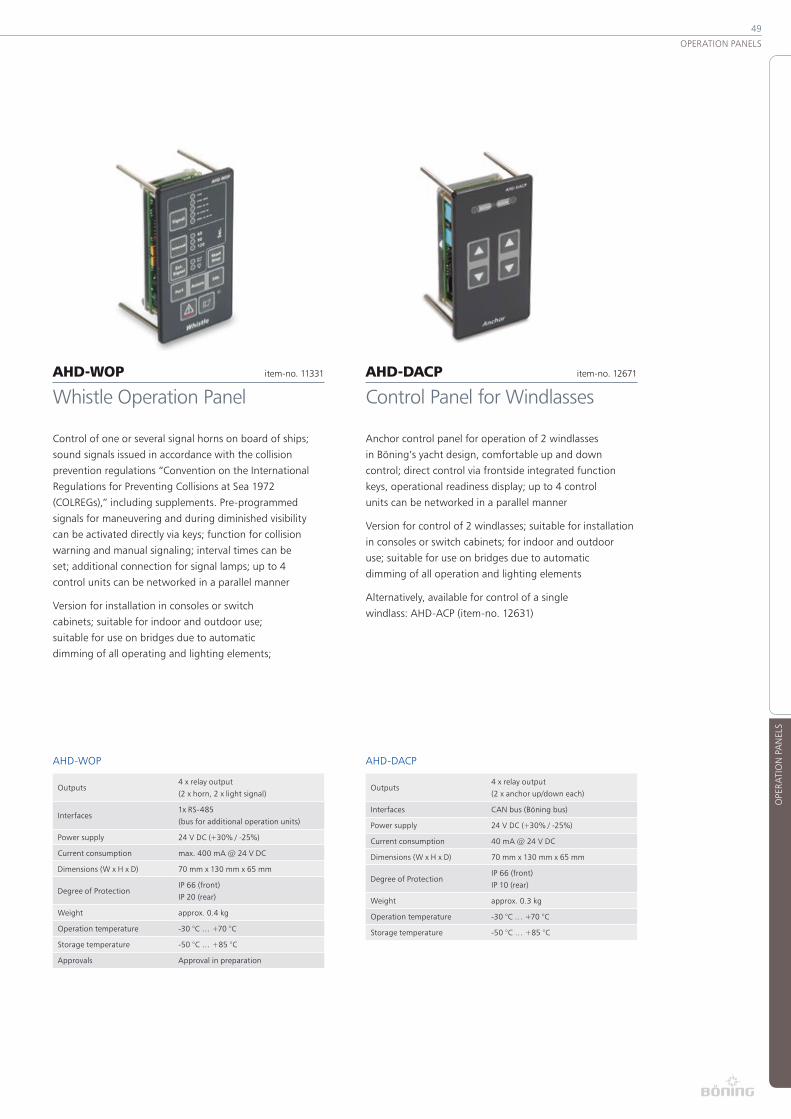
49
OPE
RATI
ON
PA
NEL
S
OPERATION PANELS
AHD-WOP item-no� 11331
Whistle Operation Panel
Control of one or several signal horns on board of ships;
sound signals issued in accordance with the collision
prevention regulations “Convention on the International
Regulations for Preventing Collisions at Sea 1972
(COLREGs),” including supplements� Pre-programmed
signals for maneuvering and during diminished visibility
can be activated directly via keys; function for collision
warning and manual signaling; interval times can be
set; additional connection for signal lamps; up to 4
control units can be networked in a parallel manner
Version for installation in consoles or switch
cabinets; suitable for indoor and outdoor use;
suitable for use on bridges due to automatic
dimming of all operating and lighting elements;
AHD-WOP
Outputs4 x relay output
(2 x horn, 2 x light signal)
Interfaces1x RS-485
(bus for additional operation units)
Power supply 24 V DC (+30% / -25%)
Current consumption max� 400 mA @ 24 V DC
Dimensions (W x H x D) 70 mm x 130 mm x 65 mm
Degree of ProtectionIP 66 (front)
IP 20 (rear)
Weight approx� 0�4 kg
Operation temperature -30 °C … +70 °C
Storage temperature -50 °C … +85 °C
Approvals Approval in preparation
AHD-DACP item-no� 12671
Control Panel for Windlasses
Anchor control panel for operation of 2 windlasses
in Böning’s yacht design, comfortable up and down
control; direct control via frontside integrated function
keys, operational readiness display; up to 4 control
units can be networked in a parallel manner
Version for control of 2 windlasses; suitable for installation
in consoles or switch cabinets; for indoor and outdoor
use; suitable for use on bridges due to automatic
dimming of all operation and lighting elements
Alternatively, available for control of a single
windlass: AHD-ACP (item-no� 12631)
AHD-DACP
Outputs4 x relay output
(2 x anchor up/down each)
Interfaces CAN bus (Böning bus)
Power supply 24 V DC (+30% / -25%)
Current consumption 40 mA @ 24 V DC
Dimensions (W x H x D) 70 mm x 130 mm x 65 mm
Degree of ProtectionIP 66 (front)
IP 10 (rear)
Weight approx� 0�3 kg
Operation temperature -30 °C … +70 °C
Storage temperature -50 °C … +85 °C

50
ENG
INE
STA
RT/S
TOP
SYST
EMS
Engine Start/Stop SystemsWith the engine operation panel AHD-EOP, maritime
diesel engines can be started and stopped conveniently
and safely� Instead of conventional ignition locks and
the associated high cabling effort, AHD-EOP uses
modern transponder technology, which contributes
to increased operational safety and also simplifies
cabling� The backboard and starboard engines are
activated and enabled for starting by inserting the
transponder key into the respective socket�
The dual engine operation panel AHD-DEOP is used
for starting and stopping two maritime propulsion
engines with comfort and ease� The device can be
installed in a separate location and works in combi-
nation with the matching key units AHD-EOP�
While the transponder key remains inserted, the
engine is operational and can be started with
any AHD-EOP or AHD-DEOP unit in the system�
This is signaled by an LED on all units�
The engine is started by pressing the start
button (AHD-EOP or AHD-DEOP)� The stop
button, in turn, stops the engine�
If the key is removed from the unit, the engine is stopped
immediately� All AHD-DEOP units can be cascaded,
resulting in easier installation of additional units�

51
ENG
INE
STA
RT/S
TOP
SYST
EMS
ENGINE START/STOP SYSTEMS
AHD-EOP item-no� 12030
Engine Operation Panel for One Ship Main Engine, Basic Module
Engine operation panel for convenient and safe starting
and stopping of one ship main engine� Release for
engine operation occurs via innovative transponder
technology, providing an increased degree of protection
against unauthorized operation; lit push buttons for
ignition, start and stop; integrated emergency stop
function and LED battery charge indicator; lit keyhole;
connection with M12 plug connection via EOP adapter
module (item no� 11823 or variants), can be cascaded
for several helms via separate input and output;
Compact design for installation in consoles, control
cabinets, and control panels; suitable for indoor and
outdoor applications; suitable for use on bridges
due to automatic dimming of all operation and light
elements; version with release for engine operation
via pluggable transponder key (not included in the
scope of delivery); on request, individual encoding
can be transferred to several transponder keys�
AHD-EOP
Combined
inputs / outputs
2 x M12 plug connector
(1 x input, 1 x output)
Power supply 24 V DC (+30% / -25%)
Current consumption 0�4 A @ 24 V DC
Dimensions (W x H x D) 70 mm x 130 mm x 66 mm
Degree of ProtectionIP 66 (front)
IP 65 (rear)
Weight approx� 0�5 kg
Operation temperature -30 °C … +65 °C
Storage temperature -50 °C … +85 °C
AHD-DEOP item-no� 11479
Dual Engine Operation Panel for Ship Main Engines, Expan-sion Module for AHD-EOP
Dual engine operation panel for safe starting and
stopping of two ship main engines, expansion module
for transponder-controlled system AHD-EOP; lit push
buttons for ignition, start, and stop; integrated emergency
stop function and LED battery charge indicator; connects
via M12 plug connections, can be cascaded for several
helms; via 2 separate inputs and outputs each;
Compact design for installation in consoles and
control panels; suitable for indoor and outdoor
applications; suitable for use on bridges due to
automatic dimming of all operation and light
elements; version without release for engine start
(this occurs externally via AHD-EOP or AHD-DEOP K)�
AHD-DEOP
Combined
inputs / outputs
4 x M12 plug connector
(2 x input, 2 x output)
Power supply 24 V DC (+30% / -25%)
Current consumption 0�4 A @ 24 V DC
Dimensions (W x H x D) 70 mm x 130 mm x 65 mm
Degree of ProtectionIP 66 (front)
IP 65 (rear)
Weight approx� 0�5 kg
Operation temperature -30 °C … +65 °C
Storage temperature -50 °C … +85 °C

52
ENG
INE
STA
RT/S
TOP
SYST
EMS
AHD-EOP K I item-no� 12214
Pair of Keys for AHD-EOP, Stainless Steel Version
Transponder keys for releasing and operating one
ship main engine via operation panel AHD-EOP�
® Patented design with paired keys, which can
be kept together with integrated magnets
® Individual encoding with AHD-EOP master
key, can be transferred to other key sets
® Version in stainless steel design housing
(K I) with “Böning” logo
Also available in buoyant plastic housing
� AHD-EOP K II (item-no� 12215)
Other versions with customer specific
logos available on request
AHD-EOP K I
Dimensions (W x H x D) 60 mm x 40 mm x 18 mm
Degree of Protection IP 67
Operation temperature -30 °C … +70 °C
Storage temperature -50 °C … +85 °C
AHD-EOP Adapter item-no� 11823
Transfer Unit for AHD-EOP
Transfer unit for simple adaptation of our
control panel AHD-EOP to the ship engine�
® Module with relay control outputs and terminal clamps
® Universal version for installation onto norm carrier
rail in control stands, consoles, or switch boxes
® Incl� M12 plug connector (EOP port)
and pluggable terminal strip
Special versions with individual adjustment of the control signals to the respective engine type for:
� MAN Vneu (item-no� 11823)
� MAN EDC (item-no� 12366)
� CAT (item-no� 12368)
AHD-EOP Adapter
Combined
inputs / outputs
1 x M12 plug connector
(1 x input)
Dimensions (W x H x D) 46 mm x 78 mm x 33 mm
Degree of Protection IP 10
Weight approx� 0�1 kg
Operation temperature -30 °C … +70 °C
Storage temperature -50 °C … +85 °C

53
ENG
INE
STA
RT/S
TOP
SYST
EMS
ENGINE START/STOP SYSTEMS
AHD-EOP EM item-no� 15496
Optional Emergency Operation Unit for AHD-EOP / AHD-DEOP
The additional safety device allows starting and stopping
the engine parallel to the regular helms, if e� g� the
transponder keys are missing� Furthermore, it can also
be used, if e� g� an unintentional start of the engines
must be prevented due to maintenance work�
Key switch positions:
® LOCAL (Operation only possible from emergency
unit, other operation units blocked)
® REMOTE (Operation from AHD-EOP / AHD-DEOP)
The engine can only be started and stopped from
this operation panel, if the key is in the LOCAL
position� In this key position, the oper-ation
panels AHD-EOP/AHD-DEOP are deactivated�
In the REMOTE position, the engines can
only be started and stopped from the opera-
tion panels AHD-EOP/AHD-DEOP�
Also available for MAN, CAT and MTU engines�
AHD-EOP EM
Combined
inputs / outputs
2 x M12 plug connector
(1 x input, 1 x output)
Power supply 24 V DC (+30% / -25%)
Current consumption 50 mA @ 24 V DC
Dimensions (W x H x D) 219�6 mm x 130 mm x 79�7 mm
Degree of Protection IP 65
Weight approx� 1�4 kg
Operation temperature -25 °C … +70 °C
Storage temperature -50 °C … +85 °C
AHD-EST item-no� 14359
Emergency Stop Control Unit
Emergency stop control unit in Böning’s
design for stopping diesel engines�
® Secured against unintentional triggering by cover flap
® Locking push button with integrated LED lighting
® Module can be cascaded,
wire break monitoring according to class possible
® Version with pluggable terminal strips
® Suitable for installation in consoles or switch panels
AHD-ORP item-no� 14220
Override-Panel
Override panel in Böning’s design for activating
the override operation for diesel engines�
Technically identical to AHD-EST (item-no� 14359)
AHD-EST /AHD-ORP
Inputs 1 x emergency stop input
Outputs 1 x emergency stop output
Power supply 24 V DC (+30% / -25%)
Current consumption 70 mA @ 24 V DC
Dimensions (W x H x D) 70 mm x 130 mm x 70 mm
Degree of ProtectionIP 66 (front)
IP 10 (rear)
Weight approx� 0�25 kg
Operation temperature -30 °C … +70 °C
Storage temperature -50 °C … +85 °C

54
MO
NIT
ORI
NG
AN
D C
ON
TRO
L SY
STEM
S FO
R N
AV
IGA
TIO
N L
AN
TERN
S
Monitoring and Control Systems for Navigation LanternsThe modular AHD-DPS 02 controls and monitors up to 42
navigation and signal lanterns on board vessels� Due to its
modular structure, the system can be matched to customer
specific requirements� It is comprised of one basic module
and up to 4 extension modules as well as a customer
specific operation panel� The system is available in different
versions for all customary voltages on board vessels,
and it can be used with conventional or LED lanterns�
The minimum configuration encompasses a basic
module for 14 lanterns and a standard operation
panel� By using additional basic modules, any number
of lanterns can be controlled and monitored�
The lanterns are controlled with an operation panel, which
provides one operation button and one LED status light
for each lamp circuit� Depending on the requirements, the
operation panels can be delivered in their standard size or
according to the customer’s wishes� Additional operation
options for touch screen or panel PC are also available�
The lamp current is provided either by the main feed or a
second, separate feed (emergency feed)� If one of these
power feeds fails, it can be manually switched over to
the other� Both currents are continuously monitored�
The internal electronics are automatically supplied by
one of the available power sources� If one lamp channel
is switched off, both switch contacts are disconnected
from the power supply with a relay� The lamp outputs are
short-circuit proof and maintenance free� The lanterns
can be controlled manually during electronics failure�
A collective alarm (closed) contact reports current
error conditions to a higher ranking alarm system�
The CAN bus or Modbus enables connection to ancillary
systems for convenient control and visualization�

55
MO
NIT
ORI
NG
AN
D C
ON
TRO
L SY
STEM
S FO
R N
AV
IGA
TIO
N L
AN
TERN
S
NAVIGATION LIGHTS MONITORING AND CONTROL SYSTEMS
AHD-DPS 02 G14 item-no� 13828
14 Channel Basic Module for Navigation and Signal Lights Control (24 V Bulb)
The basic module for controlling and monitoring
navigation and signal lamps has been constructed for 14
lamp circuits, which can be controlled and monitored
independently; lamp failures, short-circuits, or wire breaks
are alerted; in addition, operating time monitoring and
end-of-life warning (t < 2000 h) can be parametered
for each lamp circuit� The system includes a dual power
supply, which switches over to the emergency feed in
case of main feed failure� Both feeds are also monitored�
Additional features:
® Direct switching of the lamps is possible
even in case of electronics failure
® All switch channels are short-circuit proof,
automatic reset fuses enable maintenance
and exchange-free operation
® The system can be expanded to up to 42 lamp circuits
with the extension modules AHD-DPS 02 A07
® Optional communication modules AHD-DPS 02 GC
(RS-422, RS-485, CAN) available on request
Electronics unit for 24 V incandescent lamps
(bulbs) in carrier rail housing, suitable for
carrier rail mounting (TS32/35)�
Alternate versions for:
� 24 V LED lamps (item-no� 13831)
� 230 V incandescent bulbs (item-no� 14678)
� 230 V LED lamps (item-no� 14679)
� 115 V incandescent bulbs (item-no� 13830)
� 115 V LED lamps (item-no� 15113)
AHD-DPS 02 G14
Inputs1 x optocoupler input
(Alarm acknowledgment)
Outputs
14 x relay output
(2 poles, for lamps)
3 x relay contact status signals
(Common alarm, supply error,
lamp error)
Combined
inputs / outputs
1 x connection for operation unit
(ribbon cable),
1 x connection for max� 4 extension
modules (ribbon cable)
Interfaces
1 x CAN (galvanically isolated),
optional communication module
AHD-DPS 02 GC
for RS-232, RS-485 or CAN
Power supply 24 V DC (+30% / -25%)
Current consumption 420 mA @ 24 V DC
Dimensions (W x H x D) 324 mm x 126 mm x 76 mm
Degree of Protection IP 20
Weight approx� 1�05 kg
Operation temperature -30 °C … +70 °C
Storage temperature -50 °C … +85 °C
Approvals GL, LR, RMRS, CRS, BV

56
MO
NIT
ORI
NG
AN
D C
ON
TRO
L SY
STEM
S FO
R N
AV
IGA
TIO
N L
AN
TERN
S
AHD-DPS 02 BS item-no� 10945
Customer Specific Operation Panel
For controlling our navigation and signal lamp
monitoring system AHD-DPS 02 G14�
Identical technical qualities and options as standard
operating panel (see AHD-DPS 02 B14, item-no� 11414 or
variant)� Lamp control elements and labels are arranged
individually, according to tabular or graphic templates�
Depending on the application and number of lamp
channels to be controlled, various sizes are available�
Device for installation in consoles or switch boards�
Alternate versions:
� AHD-DPS 02 BS
with front frame 192 mm x 144 mm
(item-no� 11060)
� AHD-DPS 02 BS
with front frame 288 mm x 144 mm
(item-no� 11061)
AHD-DPS 02 BS
Outputs
1 x connection to basic module,
up to 4 connections to
extension modules
Power supply 24 V DC (+30% / -25%)
Current consumption 400/600/800 mA @ 24 V DC
Dimensions (W x H x D) 144/192 /288 mm x 144 mm x 64 mm
Degree of ProtectionIP 22 (front side with
protection cover IP 54)
Weight approx� 0�5 kg / 0�7 kg / 0�9 kg
Operation temperature -30 °C … +70 °C
Storage temperature -50 °C … +85 °C
Approvals GL, LR, RMRS, CRS, BV
AHD-DPS 02 B14 item-no� 11414
Operating Panel for Navigation and Signal Light Control
Operating panel for navigation and signal lamp monitoring
AHD-DPS 02 G14 for controlling 14 lamp circuits�
® Compact design for installation in consoles,
panels, and switch control boxes
® Individual ON/OFF operating keys for
14 navigation and signal lamps
® Integrated signal LEDs for displaying lamp status,
lamp fault, supply fault, and system failure
® Additional warning indicator for the lamps’
rest-of-life (2,000 hours remaining)
® All signal LEDs are automatically dimmed
® Integrated alarm buzzer and acknowledge
key with lamp test function
® Optional switch for releasing an existing remote control
(via Basic Module AHD-DPS 02 G14’s CAN port)
Device for console installation or flush mounting�
Alternate versions:
� AHD-DPS 02 B21 with 21 channels (item-no� 11481)
� AHD-DPS 02 B28 with 28 channels (item-no� 12521)
� AHD-DPS 02 B35 with 35 channels (item-no� 12522)
� AHD-DPS 02 B42 with 42 channels (item-no� 12382)
AHD-DPS 02 B14
Combined
inputs / outputs
1 x connection to basic
module (ribbon cable)
Power supply 24 V DC (+30% / -25%)
Current consumption 400 mA @ 24 V DC
Dimensions (W x H x D) 144 mm x 144 mm x 64 mm
Degree of ProtectionIP 22 (front side with
protection cover IP 54)
Weight approx� 0�5 kg
Operation temperature -30 °C … +70 °C
Storage temperature -50 °C … +85 °C
Approvals GL, LR, RMRS, CRS, BV

57
MO
NIT
ORI
NG
AN
D C
ON
TRO
L SY
STEM
S FO
R N
AV
IGA
TIO
N L
AN
TERN
S
NAVIGATION LIGHTS MONITORING AND CONTROL SYSTEMS
AHD-DPS 02 GC item-no� 12258
Communication Module
Electronics card for extending the basic module with
additional interfaces; with this, the existing lamp circuits
can be integrated into any external system� For ModBus
RTU, for insertion onto the circuit board of basic module�
Alternate versions:
� AHS-DPS 02 GC with combined
RS-485/CAN interface (item-no� 12256)
� AHD-DPS 02 GC with 4-pin
RS-422 interface (item-no� 11231)
Inputs Internal connection with basic module
Outputs Over terminal 42���46 (basic module)
Interfaces
a) 1 x CAN and 1 x RS-485,
b) 1 x RS-422,
c) 2 x RS-485 (Modbus RTU protocol)
Power supply 24 V DC (+30% / -25%)
Current consumption 20 mA @ 24 V DC
Dimensions (W x H x D) 90 mm x 20 mm x 20 mm
Weight approx� 0�02 kg
Operation temperature -30 °C … +70 °C
Storage temperature -50 °C … +85 °C
AHD-DPS 02 Selector Switch item-no� 8794
Selector Switch for Navigation and Signal Light Control System
Installation toggle switch for switching the supply voltage
of a control and monitoring system for navigation and
signal lamps� With this device, the lamp circuits are
generally supplied and a changeover between the main
and emergency feed is established� It can be connected
directly via basic module AHD-DPS 02 G14�
3 switching levels:
(0 = off, 1 = main feed, 2 = emergency feed)�
Inputs Main supply / Emergency supply
Outputs Lamp supply
Dimensions (W x H x D) 48 mm x 48 mm x 95 mm
Degree of Protection IP 65 (front)
Weight approx� 0�1 kg
Operation temperature -30 °C … +70 °C
Storage temperature -50 °C … +85 °C

58
MO
NIT
ORI
NG
AN
D C
ON
TRO
L SY
STEM
S FO
R N
AV
IGA
TIO
N L
AN
TERN
S
AHD-POS 10 item-no� 10019
Navigation Light Monitoring System for 10 Lamp Circuits
Device for monitoring the states of
10 navigation lamps on board a vessel�
® Mounted onto base plate for wall mounting in
consoles, switch panels, or switch boxes
® Input and output terminals for
connecting up to 10 lamp circuits
® Connected in the lamp circuit between
the on/off switch and the lamp�
® Lamp monitoring system with alarm
function during lamp failure
® Data transfer of status and alarm messages
to the ship alarm system via CAN bus,
including alarm acknowledgement
® LED indicator for power supply and power failure
Outputs 1 x relay contact for common alarm
Combined
inputs / outputs
10 lamp circuits with
1 x input and 1 x output
each (max� 40W)
Power supply 24 V DC (+30% / -25%)
Current consumption 150 mA @ 24 V DC
Dimensions (W x H x D) 215 mm x 120 mm x 55 mm
Degree of Protection IP 10
Weight approx� 0�6 kg
Operation temperature -30 °C … +70 °C
Storage temperature -50 °C … +85 °C
AHD-DPS 02 A07 item-no� 12337
7 Channel Extension Module (24 V bulb)
Extension module for 7 lamp circuits to expand an existing
basic module for monitoring and controlling navigation
and signal lamps� The extension module includes 7 chan-
nels� The technical qualities and options are identical to
those of the basic module (see AHD-DPS 02 G14, item no�
13828 or variant)� Every system can be expanded with up
to 4 extension modules to a maximum of 42 lamp circuits�
Electronics unit for 24 V incandescent lamps
(bulbs) in carrier rail housing, suitable for
carrier rail mounting (TS32/35)�
Alternate versions for:
� 24 V LED lamps (item-no� 12157)
� 230 V incandescent bulbs (item-no� 14674)
� 230 V LED lamps (item-no� 14675)
� 115 V incandescent bulbs (item-no� 11338)
� 115 V LED lamps (item-no� 15114)�
Outputs7 x relay output
(2 poles, for lamps)
Combined
inputs / outputs
1 x connection for operation unit
(ribbon cable),
1 x connection for max� 3 extension
modules (ribbon cable)
Power supply 24 V DC (+30% / -25%)
Current consumption 380 mA @ 24 V DC
Dimensions (W x H x D) 148 mm x 126 mm x 66 mm
Degree of Protection IP 20
Weight approx� 0�45 kg
Operation temperature -30 °C … +70 °C
Storage temperature -50 °C … +85 °C
Approvals GL, LR, RMRS, CRS, BV

59
NO
TES
NOTES

60
CCTV
VID
EO M
ON
ITO
RIN
G S
YSTE
M
CCTV Video Monitoring SystemVideo monitoring (CCTV = Closed Circuit Televi-
sion) has become a standard for increased safety
and comfort on board ships, e� g� by monitoring
public and private areas, unmanned engine rooms,
gangways, accesses, visual support of docking and
undocking maneuvers, as well as other areas�
The Video Monitoring System AHD-VCS was developed
for operating up to 16 video cameras separately, including
pan/tilt and zoom control� Here, the system components
can easily be integrated into a Böning ship alarm system,
because the same displays are used� Even the data
communication runs on the same CAN bus� There is no
need for special, separately installed camera monitors�
An unlimited number of control units can be connected�
The system’s main components are: Video Distribution
Control Unit AHD-VDCU (for 4, 8, or 16 cameras), Video
Control Panel AHD-VCP, and the touch screen color
displays AHD 1215/AHD 1219 or AHD 880 with individual,
separate control units� The Video Distribution Control Unit
AHD-VDCU processes and controls the camera signals and
forwards their video signals to the connected displays�
You can choose from various models for standard
and special applications� The robust cameras meet
the requirements of a maritime environment and
are protected against vandalism� As a rule, they
are controlled and powered by the Video Distribu-
tion and Control Unit AHD-VDCU� Models with a
higher current consumption or nonstandard power
supply are powered by a separate source�
The video monitoring system can be expanded with
an optional Video Quad Processor AHD-VCS Q 4-1,
by which four selected cameras can be viewed on a
single screen� Another available option is the Digital
Video Data Recorder AHD-VC VR8 with 8 loop through
inputs, 320 GB internal hard disk (data compression
MPEG-4), DVD-R/W, and several other functions�

61
CCTV
VID
EO M
ON
ITO
RIN
G S
YSTE
M
CCTV VIDEO MONITORING SYSTEM
AHD-VDCU 16/16 item-no� 11605
16 x 16 Video Distribution Control Unit Central Unit with 16 x Video-In and 16 x Video-Out
Video distribution control unit for the distribution and
control of video signals received from video systems (video
cameras�) The video signals may be transferred to displays,
television sets, video data recorders and other video
processing systems� AHD-VDCU 16/16 operates autono-
mously or integrated into an installed ship alarm system�
The unit is operated via CAN bus or RS-485 with a
separate video control unit or control elements on
the connected color displays' visualization pages�
Version for bulkhead mounting�
Other versions:
� AHD-VDCU 8/8
8 x Video-In and 8 x Video-Out
(item-no� 11417)
� AHD-VDCU 4/4
4 x Video-In and 4 x Video-Out
(item-no� 11758)
AHD-VDCU 4/4
Inputs
4 camera inputs with RJ45 sockets
for connection of video cameras
with one standard CAT5 network
cable for transmission of video
signals, camera control signals and
12 V DC camera power supply
Outputs
4 video outputs (BNC connectors)
for 75 Ohms coaxial cable (RG-59)
(transmission of video signals,
1 Vpp, 75 Ohms)
Interfaces 1 x CAN, 1 x RS-485
Power supply 24 V DC (+30% / -25%)
Current consumption
0�36 A @ 24 V DC
(plus max� 400 mA/camera when
supplied via camera input)
Dimensions (W x H x D) 330 mm x 160 mm x 42 mm
Degree of Protection IP 20
Weight approx� 1�2 kg
Operation temperature -30 °C … +70 °C
Storage temperature -50 °C … +85 °C
AHD-VCS Q4-1 item-no� 11824
Video Quad-Screen Processor Unit (Quadrant Divider)
Video quad-processor in surface mountable housing for
integration into consoles or switch panels� 4-channel
color quadrant divider for mixing 4 video input signals in a
single video output signal with quad-screen presentation�
® Preset for use in a video system with video
standard PAL 1024 x 624 pixels
® 4 loop-through channels (1 Vpp, 75 Ohm), each
with BNC connection for video input and output
® 1 live-image monitor (1 Vpp, 75 Ohm) with
BNC connection for quad, full screen, and
auto sequence presentation output�
AHD-VCS Q4-1
Inputs
4 loop through channels on input side
(1 Vpp, 75 Ohm), 1 VCR IN
video input (1 Vpp, 75 Ohm), 4 alarm
inputs (NO/NC contact, selectable)
Outputs
4 loop through channels
on output side (1 Vpp, 75 Ohm),
1 VCR OUT video output
(1 Vpp, 75 Ohm),
1 Live image monitor output
(1 Vpp, 75 Ohm)
1 relay output (NO/NC contact)
Interfaces 1 x RS-232
Power supply
12 V DC (+30% / -25%) or
24 V DC over AHD-VSC QC,
resp� (see page 66)
Current consumption max� 0�85 A @ 12 V DC
Dimensions (W x H x D) 216 mm x 45 mm x 214 mm
Degree of Protection IP 20
Weight approx� 2�5 kg
Operation temperature 0 °C … +50 °C
Storage temperature -10 °C … +85 °C

62
CCTV
VID
EO M
ON
ITO
RIN
G S
YSTE
M
AHD-VC VR8/16 item-no� 13472
Video Recorder
The digital video data recorder AHD-VC VR8 is used
for data storage of video signals from connected
cameras or other video signal sources�
The device is notable for its ease of use
and convenient range of features�
® Simultaneous processing of up to
8 video channels
® Video standards: SVGA; PAL/NTSC
® Auto recognition or menu selectable
Hard drives:
2 SATA solid hard drives, max� 2 TB, Compression: H�264
Inputs
Composite Video 1 Vss, 75 Ohm,
automatic termination;
PAL/NTSC,
Automatic recognition
Video: 8/16 BNC (loop through),
automatic termination
Audio: 4 RCA (Cinch)
Outputs
Monitor A – VGA RGB
Monitor B – VGA RGB
Audio: 2 RCA
Interfaces
1 x CAN Ethernet:
RJ45, 10/100/1000BaseT
according to IEEE802�3
Monitors: VGA D-Sub (2)
USB 2�0: at front and rear side
for mouse and USB storage devices
Power supply 100���240 V AC 50/60 Hz
Current consumption max� 1�8 A
Dimensions (W x H x D) 355 mm x 88 mm x 362 mm
Degree of Protection IP 20
Weight approx� 4�3 kg
Operation temperature 0 °C … +40 °C
Storage temperature -40 °C … +70 °C
AHD-VCP item-no� 11332
Video Control Panel
The video control panel AHD-VCP is used for
selecting and controlling the video cameras
connected to the video monitoring system�
The unit is connected to the CAN bus, communicating
with the video distribution control Unit AHD-VDCU�
All available function for controlling the camera can
easily and comfortably selected by keystrokes�
Interfaces 1 x CAN
Power supply 24 V DC (+30% / -25%)
Current consumption 40 mA @ 24 V DC
Dimensions (W x H x D) 70 mm x 130 mm x 46 mm
Degree of ProtectionIP 66 (front)
IP 10 (rear)
Weight approx� 0�3 kg
Operation temperature -30 °C … +55 °C
Storage temperature -50 °C … +85 °C

63
CCTV
VID
EO M
ON
ITO
RIN
G S
YSTE
M
CCTV VIDEO MONITORING SYSTEM
AHD-VC 731 item-no� 13696
FlexiDome Color Camera, Pan/Tilt Function, Manual
The FlexiDome camera AHD-VC 731 is a high-resolution
color camera, manual pan/tilt function and variofocus lens�
® 1/3” Interline Transfer CCD, 752 x 582 pixels (PAL)
® High resolution (color: 540 TV lines; B/W: 570 TV lines
® 360° endless rotation; 0° … 90° tilt, +/-90° azimuth
® Variofocus lens F1/2�6/2�6-6�0 mm (47° - 95° h)
® Light sensitivity < 0�7 lux with NightScene
function for increased sensitivity
® Elegant, vandalism proof aluminum die-cast housing
with PC dome hood for ceiling installation�
Power supply10�8 - 39 V DC /
12 ��� 28 V AC, 45 ��� 65 Hz
Current consumption0�17 A
(0�25 A with internal heating)
Dimensions (∅ x H) 158 mm x 85 mm
Degree of Protection IP 66
Weight approx� 0�74 kg
Operation temperature -20 °C … +45 °C
Storage temperature -40 °C … +70 °C
AHD-VC 753 item-no� 14554
Motor Dome Color Camera, Pan/Tilt Function, Remote Controlled
The motor dome camera AHD-VC 753 is a
high-resolution color camera with remote cont-
rolled pan, tilt, zoom, and focus function�
® 1/4“ Sony Super HAD CCD, 752 x 582 pixels (PAL)
® 10 x optical zoom with 10x digital zoom
® High resolution (color: 520 TV lines; B/W: 570 TV lines)
® Intelligent pan/tilt control
® 360° endless rotation; 0° … 180° tilt (auto flip mode)
® 0�05°/sec� … 360°/sec� pan/tilt speed
® Vector drive technology; switchable day/
night function (ICR blocking filter)
® Can be remote controlled via control
units or touch screen
® OSD menu (7 languages)
® Numerous monitoring functions: privacy
masking; password protected; elegant,
vandalism proof aluminum housing with
PC dome hood for ceiling mounting
Power supply 12 V DC
Current consumption 0�67 A (1 A with internal heating)
Dimensions (∅ x H) 165 mm x 162 mm
Degree of Protection IP 66
Weight approx� 1�85 kg
Operation temperature -10 °C … +50 °C
Storage temperature -10 °C … +60 °C

64
CCTV
VID
EO M
ON
ITO
RIN
G S
YSTE
M
AHD-VC 711 item-no� 13744
Bullet Miniature Color Camera, Pan/Tilt Function, Manual
Bullet miniature color camera, manual pan/tilt function�
The bullet miniature color camera AHD-VC 711 is a
high-resolution camera for monitoring still images�
® Vandalism proof aluminum die-cast housing�
® Adjustable socket for surface mounting
® 1/3” CCD sensor
® Resolution: color 700 TV lines
® Light sensitivity < 0�1 lux
® Lens 3�6 mm (69° h)
® Integrated preconfigured connection cable
Power supply 12 V DC
Current consumption 83 mA
Dimensions (∅ x H) approx� 23 mm x 91 mm
Degree of Protection IP 67
Weight approx� 0�07 kg
Operation temperature -10 °C … +50 °C
Storage temperature -10 °C … +60 °C
AHD-VC 720IR item-no� 12263
Infrared Dome Color Camera, Pan/Tilt Function, Manual
Infrared dome color camera, manual pan/tilt function�
The infrared dome color camera AHD-VC 720 is a
high-resolution camera for still image monitoring�
® 1/3“ Sony Super HAD CCD,
® Manually controlled variozoom lens 4�0-9�0 mm, DC,
® Min� light sensitivity 0�5/0�004 lux,
® Manually controlled 360° rotation,
® Manually controlled tilt 10° … 90°,
® IR-LED reflector with a range of up to 15 m
Power supply 12 V DC
Current consumption 0,5 A
Dimensions (∅ x H) 120 mm x 96 mm
Degree of Protection IP 66
Weight approx� 1�85 kg
Operation temperature -10 °C … +50 °C
Storage temperature -10 °C … +60 °C

65
CCTV
VID
EO M
ON
ITO
RIN
G S
YSTE
M
CCTV VIDEO MONITORING SYSTEM
AHD-VC 741 item-no� 13768
Bulbous Bow/Dolphin Camera
Plettac color camera FAC 940L, in a submer-
sible, special installation casing for bulbous bow
installation (installation kit item-no� 13390)�
® ½“ Interline Hyper HAD CCD chip
® 752 x 582 pixels (PAL)
® High resolution (color: 580 TV lines hor� CVBS)
® Lens F1�4/4�5 mm, (79° h), SCS
® Light sensitivity < 0�05 lux
® Bronze aluminum and 5083 aluminum casing
® Glass lens borosilicate glass
Power supply 10 V DC … 29 V DC
Current consumption 50 mA @ 12 V DC
Dimensions (∅ x H)70 mm x 61�5 mm camera
130 mm x 222 mm housing
Degree of ProtectionIP 68 (front)
IP 44 (rear) / 10 bar housing
Weight approx� 3 kg
Operation temperature -30 °C … +70 °C
Storage temperature -50 °C … +85 °C
AHD-VC 740 item-no� 12969
Anchor Pocket Camera with LED Spot Light
Color camera and additional LED spot light,
each in a submersible special installation casing
for installation in the anchor pocket�
Camera:
® 1/3” Sony CCD chip, 752 x 582 pixels (PAL)
® High resolution (color: 540 TV lines)
® Lens 4�0 – 9�0 mm; manually operated zoom
® Light sensitivity 0�1/0�0 lux
LED spot light:
® 7 single-LED 110 lumens
® 30000 hrs� operating life
® 7000 K color temperature, 3500 lumen light output
® Aluminum bronze and 770 aluminum casing
® Glass lens borosilicate glass
Power supply 12 V DC
Current consumption300 mA (camera),
1�6 A (LED spotlight)
Dimensions (∅ x H)82 mm x 325 mm camera
82 mm x 138�5 mm LED spotlight
Degree of ProtectionIP 68 (front)
IP 44 (rear) / 10 bar housing
Weightapprox� 1�5 kg camera
approx� 1 kg LED spotlight
Operation temperature -30 °C … +70 °C
Storage temperature -50 °C … +85 °C

66
CCTV
VID
EO M
ON
ITO
RIN
G S
YSTE
M
AHD-VSC CB item-no� 14551
Video Signal Converter for AHD-VC Cameras with BNC Plug
Same function as AHD-VSC C, BNC connection
Specifications: see AHD-VCS C (Item-no� 11720)
AHD-VSC CFV item-no� 13684
Video Signal Converter for FLIR Voyager
The video signal converter AHD-VSC CFV is used for
connecting a Voyager camera by FLIR Systems to
the video distribution central unit AHD-VDCU with
a CAT5 cable� The signal converter integrates video
signal transmission and camera control commands�
Specifications: see AHD-VCS C (item-no� 11720)
AHD-VSC CF item-no� 13574
Video Signal Converter for FLIR Navigator II
As AHD-VSC CFV (item-no� 13684),
but for FLIR Navigator II cameras�
Specifications: see AHD-VCS C (item-no� 11720)
AHD-VSC QC item-no� 11957
Video Signal Converter for Video Quad-Screen Processor Unit
The video signal converter AHD-VSC QC is used for
connecting the video quad-screen processor unit
AHD-VSC Q4-1 to the video distribution central unit
AHD-VDCU with a CAT5 cable and BNC plug�
Specifications: see AHD-VCS C (item-no� 11720)
AHD-VSC C item-no� 11720
Video Signal Converter for AHD-VC Cameras with Terminal Clamp Connections
The video signal converter AHD-VSC C is used for connec-
ting standard AHD-VSC cameras to the video distribution
control unit AHD-VDCU with a CAT5 cable� The connection
encompasses the transmission of video signals and control
commands as well as the cameras’ power supply�
® Conversion of the camera’s video output signal to a
differential signal for increased transmission quality�
® Transformation of the 24 V DC power supply
from the video central unit to the required
standard 12 V DC camera power supply
® Integration of the RS-485 data cable for
transmitting the camera control commands�
® Housing with preconfigured connection cable for
camera connection and RJ45-coupling for the CAT5
cable’s plug connection� Internal electronic circuits
encapsulated to increase the protection class�
AHD-VSC C
Power supply 24 V DC (+30% / -25%)
Current consumptionElectronics: 60 mA (24 V DC)
Output: 12 V / 1 A
Dimensions (∅ x L) 35 mm x 85 mm
Degree of Protection IP 20
Weight approx� 0�1 kg
Operation temperature -30 °C … +55 °C
Storage temperature -50 °C … +85 °C

67
CCTV
VID
EO M
ON
ITO
RIN
G S
YSTE
M
CCTV VIDEO MONITORING SYSTEM
® Image sensor focal plane,
vanadium oxide (Vox),
micro bolometer, uncooled
® 240 x 180 pixels (HM-224),
320 x 240 pixels (HM-324 XP+)
® Spectral range 7�5 … 13�5 µm
® Viewing angle 24° (h) x 18° (v), 12° (h)
x 9° (v) with 2 x extender lens
® Thermal sensitivity < 50 mK at f1�0 and + 25°C
® Frame rate 8�3 Hz PAL/7�5 Hz NTSC
® Internal LCD screen
® Image storage single frame, standard
JPEG (HM-324 XP+)
® Video storage 9 Hz, full frame, MPEG4,
(appr� 8 sec�/MB) (HM-324 XP+)
® Image polarity white-hot or black-hot, selectable
® SD card slot for 1 GB card, USB 2�0 (HM-324 XP+)
® Video output PAL or NTSC composite
video, RCA coupling
Power supply 4 x AA NiMH Akku (incl�)
Battery Service Life > 5 h
Dimensions (W x H x D)
240 mm x 85 mm x 60 mm
(HM-224)
265 mm x 85 mm x 75 mm
(HM-324 XP+)
Degree of Protection IP 67
Weightapprox� 0�66 kg (HM-224)
approx� 0�97 kg (HM-324 XP+)
Operation temperature0 °C … +50 °C (HM-224)
-20 °C … +60 °C (HM-324 XP+)
Storage temperature-20 °C ��� +70 °C (HM-224),
-40 °C ��� +75 °C (HM-324 XP+)
HM-Series, FLIR Systems item-no� on request
Portable Thermal Imaging Camera for Maritime Applications
Portable thermal imaging cameras for mari-
time applications (no integration into the
video control system AHD-VCS)�
HM-series thermal imaging cameras are portable and
impact resistant� They create a crisp image, even in the
darkest night, dramatically increasing your ability to
observe your environment� The HM-series can be used on
all types of vessels� Many yachts, merchant vessels, working
vessels, as well as police and government boats can
profit from the thermal imaging cameras’ performance�

68
CCTV
VID
EO M
ON
ITO
RIN
G S
YSTE
M
MU/MV-Series, FLIR Systems item-no� o� req�
Premium Multi-Sensor Systems for Maritime Applications
The FLIR MU-series is the technologically most advanced
thermal night vision system available to the maritime
industry today� It is a powerful, gyro stabilized multi-
sensor, long range, thermal night vision system�
FLIR MV-series provides a thermal imaging camera
equipped with an uncooled Vanadium Oxide (VOx)
detector producing thermal images of 640 x 480
pixels� It is the more affordable multi-sensor solu-
tion� The thermal imaging camera zooms in a
field of view between a 24�5° and a 4°�
® Stepless 360° pan, tilt +/- 90°
® Active gyro stabilization provides steady
images, even in rough seas
® Radar tracking
® Video tracking: the user can select a given target that
can be automatically tracked by the video tracker
® Picture-in Picture mode
® Digital detail enhancement (DDE) ensures
a crisp thermal image even in scenes with
extreme temperature dynamics
® Different versions available
Power supply12 V DC ��� 24 V DC (-10% / +30%)
(Supply directly connected to camera)
Current consumption 75/100 W nominal, max� 200 W
Dimensions (∅ x H) 510 mm x 454 mm
Degree of Protection IP 66
Weight approx� 27 kg
Operation temperature -30 °C … +55 °C
Storage temperature -40 °C … +70 °C
M-Series, FLIR Systems item-no� on request
Premium Multi-Sensor Systems for Maritime Applications
The M-series combines a thermal imaging camera with
a highly sensitive low light camera� It provides a crisp,
clear thermal image in complete darkness and light fog or
smoke� Integrated in a small, ultra compact gimbal, it is
suitable for even the most demanding applications at sea�
The FLIR M-series provides the optimal instruments for
navigation at night, on-board safety, man-over-board
situations, protection from piracy, and many other appli-
cations� The FLIR M-series sets the standard for maritime
thermal imaging systems by which all others are measured�
® Combined thermal imaging and high-sensitivity
low light camera with controllable pan/tilt head
® Stepless 360° pan, tilt +/- 90°
® Image sensor focal plane, vanadium oxide
(VOx) micro bolometer, uncooled
® 640 x 480 pixels (thermal image M-626L),
320 x 240 pixels (thermal image M-320L, M324XP)
® Spectral range 7�5 … 13�5 µm
® Viewing angle 26° (h) x 20° (v) with 35 mm lens
® Thermal sensitivity < 50 mK at f/1�0 and +25° C
® Low light camera (M-626L, M-320L)
½” Interline Transfer CCD
® Different versions available
Power supply12 V DC ��� 24 V DC (-10% / +30%)
(Supply directly connected to camera)
Current consumption 25 W nominal, max� 50 W
Dimensions (∅ x H) 178 mm x 279 mm
Degree of Protection IP 66
Weight approx� 4�1 kg
Operation temperature -25 °C … +55 °C
Storage temperature -40 °C … +85 °C

69
CCTV
VID
EO M
ON
ITO
RIN
G S
YSTE
M
CCTV VIDEO MONITORING SYSTEM
Voyager II, FLIR Systems item-no� 13464
Gyro Stabilized Multi-Sensor Thermal Imager for Night Applications
Gyro stabilized thermal imager with pan/tilt for maritime
night vision applications� Powerful multi-sensor night
vision system operating in the mid-range of the infrared
spectrum� It encompasses two thermal imaging cameras
and one high-sensitivity low light camera� Ideal for
navigation and environmental observation� Allows the
user to zoom in on very small or distant objects� It also
allows recognition of human sized objects at a distance
of over 2 km� Objects 2�3 m x 2�3 m in size that are
drifting on the water can practically be recognized even in
complete darkness, through smoke, light fog, and in the
most diverse weather conditions at a distance of 6 km�
Voyager II can be connected to a radar system in a
so-called “slew to crew” configuration� Voyager II can
identify and track radar targets, using the National
Marine Electronics Association (NMEA) 0183 protocol�
When activated and when an object has been recognized,
Voyager II automatically turns to the correct direction
and tracks the object, so that you can clearly recognize
what the blip on the radar screen really means�
Power supply24 V DC (-10% / + 30%) (Supply
directly connected to camera)
Current consumption50 W nominal, max� 130 W,
with heating max� 270W
Dimensions (∅ x H) 381 mm x 584 mm
Degree of Protection IP 66
Weight approx� 20�4 kg
Operation temperature -25 °C … +55 °C
Storage temperature -50 °C … +85 °C

70
TRIM
TA
BS C
ON
TRO
L SY
STEM
Trim Tabs Control SystemDeveloped and patented by Böning, the electrohy-
draulic trim tabs control system was designed for
use with fast yachts whose cruising behavior is
significantly affected by controlling the trim tabs�
The backboard or starboard trim tabs’ single or dual
action electrohydraulic cylinders are controlled with
the electronic directional valves of the hydraulic
aggregates AHD-TCS HYD� A particular characteristic
of the system is the dispensation of cabling, which
is often prone to error, on the vessel’s exterior�
Instead of customary hydraulic displacement transducers,
special flow meters converting the movement of the
hydraulic fluid into impulses are used� These impulses are
processed by the electronic control unit AHD-TCS A and
are used for the exact calculation of the trim tab positions�
Automatic trim tab retraction ensures that the cylinders’
pistons and gaskets are protected from fouling�
If the system is expanded with a GPS receiver
(directly at the electronic control unit AHD-TCS A),
the trim tabs can also be controlled in automatic
mode� For this purpose, the optimal trim tabs’
position at various cruising speeds is determined and
saved during the shipyard side commissioning�
The electronic control unit AHD-TCS A transmits all
data over a CAN bus� Thus, the trim tabs position
can be depicted graphically (visually) on a color
display (e� g� AHD 651 or AHD 880)� The display
can also be part of an existing ship alarm system�
It is accessed directly by the electronic control unit
AHD-TCS A via two analog outputs (0-10 V DC)�
The control unit, display, and optional control
instruments can be cascaded (e� g� for fly bridge)�
Control electronics failure is detected via CAN
bus and shown on the connected displays�

71
TRIM
TA
BS C
ON
TRO
L SY
STEM
TRIM TABS CONTROL SYSTEM
AHD-TCS A item-no� 10167
Electronic Control Unit for Trim Tabs Control System AHD-TCS
AHD-TCS A is the central control unit of the Trim
Tabs Control System AHD-TCS� It processes all sensor
data and transmits these data via CAN bus to a color
display (e� g� AHD 651 or AHD 880) for visualization�
A failure of the control electronics is captured via CAN
bus and indicated on a connected display� Even when
the control unit AHD-TCS A fails the trim tabs can be
controlled with the operation panel AHD-TCS OP A�
Three additional outputs are available for the
direct control of analog position indicators�
® Optional capture and evaluation of
the current inclination angle
® Electronics unit in profile carrier housing,
suitable for carrier rail mounting (TS32/32)
Recommended accessories:
� Operation panel AHD-TCS OP A (item-no� 10168)
� AHD-TCS INCL Inclination sensor for measuring
the inclination angle (item-no� 11944)
Inputs2 x flowmeter,
1 x operation unit
Outputs2 x hydraulic aggregates,
3 x gauges
Interfaces1 x CAN (galvanically isolated),
1x RS-232
Power supply 24 V DC (+30% / -25%)
Current consumption 0�15 A @ 24 V DC (electronics)
Dimensions (W x H x D) 215 mm x 120 mm x 48 mm
Degree of Protection IP 10
Weight approx� 0�7 kg
Operation temperature -30 °C … +70 °C
Storage temperature -50 °C … +85 °
AHD-TCS OP A item-no� 10168
Operating Panel for Trim Tabs Control System AHD-TCS
Enables manual or automatic operation of the
electrohydraulic Trim Tabs Control System AHD-TCS�
® Compact design for inside and outside operation
® Illuminated push buttons, automatic dimming of LEDs
® Connection to control unit AHD-TCS A with 8-pole cable
® Cascadable (e� g� for installation in fly bridge, bridge)
Inputs 1 x input (feedback)
Outputs 5 x output (key commands)
Power supply 24 V DC (+30% / -25%)
Current consumption 0�1 A @ 24 V DC
Dimensions (W x H x D) 70 mm x 130 mm x 94 mm
Degree of ProtectionIP 66 (front)
IP 10 (rear)
Weight approx� 0�25 kg
Operation temperature -30 °C … +70 °C
Storage temperature -50 °C … +85 °
AHD-TCS INCL item-no� 11944
Inclination Angle Sensor for Trim Tabs Control System AHD-TCS
In conjunction with operation panel AHD-TCS A, the
inclination angle sensor AHD-TCS INCL enables optimizing
the trim tabs positioning, depending on the heel while
cruising� Version with mounting flange�
Power supply 20 ��� 30 V DC
Ausgang 4 ��� 20 mA
Dimensions (W x H x D) 40 mm x 41 mm x 52 mm
Degree of Protection IP 67
Weight approx� 0�1 kg

72
TRIM
TA
BS C
ON
TRO
L SY
STEM
Draghetti Marine Division
Trim Tabs
� MD 350 300 mm x 310 mm (item no� 14232)
� MD 500 500 mm x 310 mm (item no� on request)
� MD 750 750 mm x 410 mm (item no� on request)
� MD 800 800 mm x 410 mm (item no� on request)
� MD 1000 1000 mm x 460 mm (item no� on request)
� MD 1800 1800 mm x 460 mm (item no� on request)
Draghetti Marine Division
Hydraulic Cylinders
Version MD 1632 (item no� 14230)
Type Double effect
Stroke 80 mm
Pressure 90 bar
Connections M12 x 1�5
Weight 3�85 kg
Force 6360 N
Version MD 2540 (item no� on request)
Type Double effect
Stroke 80 mm
Pressure 90 bar
Connections M12 x 1�5
Weight 5�705 kg
Force 11309 N
AHD-TCS HYD item-no� 10793
Hydraulic Aggregate for Trim Tabs Control System AHD-TCS
AHD-TCS HYD is a complete hydraulic aggregate
for hydraulic control of single or double-action
cylinders operating trim tabs� Each trim tab
requires a separate hydraulic aggregate�
® Mounting plate for installation close to the trim tabs
® Available in versions with hydraulic
aggregates for 1 or 2 trim tabs
® Hydraulic pump with terminal clamps
for 24 V DC power supply
® Hydraulic oil container min� 0�75 l
® Distribution block with flow meter, incl�
terminal clamps for 24 V DC
® Power supply and signal outputs (pulse left/right)
Not included in delivery: hydraulic cylinders
for the trim tabs, tubes for the hydraulic cylin-
ders and other installation material�
Inputs Aggregate (control up, down)
Outputs Flow (signal up, down)
Power supply 24 V DC (+30% / -25%)
Current consumption typ� 16 A @ 24 V DC
Dimensions (W x H x D) 240 mm x 351 mm x 200 mm
Degree of Protection IP 56
Weight approx� 11 kg
Operation temperature -25 °C … +70 °C
Storage temperature -30 °C … +85 °C

73
TRIM
TA
BS C
ON
TRO
L SY
STEM
TRIM TABS CONTROL SYSTEM
New Function for Böning Trim Tabs Control SystemAs of now, the innovative Trim Tabs Control System
ADH-TCS can also be ordered with an optional inclina-
tion sensor� While cruising, the ship’s electronics unit
automatically compensates for inclinations caused by
e� g� asymmetrical loads, cross winds, or sea currents�
The speed-dependent automatic control system
improves the yacht’s maneuverability and furthermore
achieves a fuel savings of up to 10 % at top speed�
Each optimal trim tab position is precisely
calculated by a patented process using flow
meters at the hydraulic pump� The system is
maintenance friendly and robust, since no sensors
are installed on the exterior of the vessel’s hull�
Thanks to a special cooperation with the Italian
hydraulics specialist Draghetti Marine, we can
assemble a complete system, tailored to the
customer’s individual requirements� In addition, our
partner has further improved his trim tabs� The new
generation’s curved design offers greater buoyancy
over conventional trim tabs of the same size�
The electronic control unit AHD-TCS A transmits all
data over a CAN bus� Thus, the trim tab position
can be shown graphically (visually) on a color
display (e� g� AHD 651 or AHD 880 TC)� The display
can be part of an existing ship alarm system�
The control unit, display, and optional control
instruments can be cascaded (e� g� for fly bridge)�
Control electronics failure is detected via the CAN
bus and shown on the connected displays�
AHD-TCS OP A
AHD 880 G
AHD-TCS A
AHD-TCS HYD

74
DIE
SEL
ENG
INE
MO
NIT
ORI
NG
AN
D S
AFE
TY S
YSTE
MS
Diesel Engine Monitoring and Safety SystemsWith the new AHD 514 system components, we
provide a compact monitoring system for ship main
engines and gensets� All required inputs and outputs
as well as the corresponding monitoring and control
functions are fully integrated� The system encompasses
a monitoring unit with start/stop function, a safety unit
with integrated emergency stop function, as well as
a display and control unit with a 5�7” color display�
The components’ design focuses on easy installation and
operation� For the most part, the system components
can be connected directly with terminal strips, leading
to a significant reduction in material and installation
costs� The system is approved by GL and other leading
classification societies� The PC based configuration
software, included in the delivery, makes it possible to
adjust all necessary parameters at various user levels�
AHD 514 A Start/Stop System with Combined Alarm System for Diesel Propulsion Engines
Compact unit in module housing for console, switch
panel, or control cabinet installation onto Profile Carrier
Rails TS32/35� The AHD 514 A includes numerous
inputs and outputs, whose functions are configurable
for the most part� Thus, all required sensors, including
engine speed and safety relevant (redundant) sensors
are captured and processed� Threshold violations are
alerted, and the engine is automatically stopped during
overspeed� Various operational states can be transmitted
via relay contacts� The diesel engine’s start and stop,
as well as alerting and presentation of all data, occurs
via the connected Display and Operation Unit AHD 514
OP� Alarms and events are logged internally and can be
retrieved at a later point� An optional remote control
unit allows for controlling the system remotely�
AHD 514 S Safety System with Combined Emergency Stop System for Diesel Propulsion Engines
Compact unit in module housing for console, switch
panel, or control cabinet installation onto Profile
Carrier Rails TS32/35� All safety functions required
by the classification societies, such as wire break
monitoring of the inputs and outputs, are integrated�
The emergency stop circuit includes a separate 24 V
DC feed, which operates independently of the other
safety functions� An initiated emergency stop is sent
directly to the emergency stop exit� During an alarm, the
safety relevant sensors activate the stop circuit� Alerts
are reported locally via integrated LEDs as well as on a
connected Display and Operation Unit AHD 514 OP�
AHD 514 OP Display and Operation Unit for AHD 514 Propulsion Diesel Monitoring System
Built-in device with 5�7” color display and keypad for
local installation in the diesel engine’s control cabinet
and/or as remote control unit in the bridge console
(optional)� All relevant operational data are visualized
on a bright, high resolution display (640 x 480 pixels,
500 cd/m²)� The presentation is distributed in a clearly
organized manner and across several pages� Current
alarms are indicated by activating an internal buzzer
and a red, flashing alert message� Built-in pushbuttons
provide start and stop, alarm quit, and reset functionality,
as well as the ability to navigate between pages�

75
DIE
SEL
ENG
INE
MO
NIT
ORI
NG
AN
D S
AFE
TY S
YSTE
MS
DIESEL ENGINE MONITORING AND SAFETY SYSTEMS
AHD 514 A item-no� 12972
Monitoring System for Diesel Engines: Alarm System with Combined Start/Stop System
The AHD 504/AHD 514 series diesel engine monitoring
system has been designed as a compact solution for
starting, stopping, and monitoring diesel engines on
board of ships or in onshore installations� Combined with
the Safety System AHD 514 S, it provides a complete
package solution for wide-ranging fields of application�
AHD 514 A is an engine start/stop system with combined
alarm system� The integrated processor system processes
and monitors up to 15 sensors for the capture of
currents and resistances, changeover contacts and
engine speeds� Control inputs and potential free relays
contacts round up the system to an compact reliable unit�
Electronics unit in profile carrier housing, suitable for
carrier rail mounting (TS32/35�) The overall system is
configured with an included software package, which
allows individual adjustments at several authorization
levels to various engine manufacturers' model series�
Inputs
15 x analog input
(sensor type = 4-20 mA, PT100,
PT1000, frequency or contact)
9 x optocoupler input:
1 x serial , 8 x control
Outputs
1 x analog
(4-20 mA / 1-5 V / 2-10 V),
2 x serial optocoupler output (for
example for AHD-R 101),
10 x switching output
(start, stop, horn, common alarm,
status and group alarms)
Interfaces2 x CAN (galvanically isolated),
1 x serial (RS-232)
Power supply 24 V DC (+30% / -25%)
Current consumption 210 mA @ 24 V DC
Dimensions (W x H x D) 238 mm x 140 mm x 77 mm
Degree of Protection IP 20
Weight approx� 0�7 kg
Operation temperature -30 °C … +70 °C
Storage temperature -50 °C … +85 °C
Approvals GL, DNV, LR, BV, ABS, RMRS, RINA, CRS
AHD 514 S item-no� 12973
Monitoring System for Diesel Engines: Safety System with Emergency Stop
AHD 514 S is a safety system for monitoring all safety
relevant (redundant) sensors and criteria according
to classification society guidelines� integrated
autonomous emergency stop system with separate
feed, functional even during failure of the remaining
alarm system� Processor system with autonomous
data processing and direct alerting via potential-free
contacts (horn activation and collective alarm)�
Inputs with wire break monitoring for capturing 5
safety relevant sensors, 2 emergency stop switches
as well as pulse generator (engine speed), 5 control
inputs (acknowledgement, reset, override, and other
functions), 4 universal relay outputs (system status
and alerting), 2 switching outputs (wire break moni-
tored) for engine safety stop and optional air flap� 1
analog output (4-20 mA, 1-5 V/2-10 V)� 10 frontside
LED indicators for direct, local fault indication�
Preconfigured standard version for shared operation
with alarm system AHD 504 A/AHD 514 A�
Alternatively available as preconfigured device for
standalone solutions (type: AHD 514 S1/item-no� 15431)�
additional customer specific solutions available on request�
Inputs
5 x binary inputs
(sensor type = contact)
5 x optocoupler inputs
(control)
Outputs
1 x analog
(4-20 mA / 1-5 V / 2-10 V),
1 x serial optocoupler output,
7 x switching output
(safety stop, emergency stop, horn,
common alarm, status)
Interfaces 1 x CAN (galvanically isolated)
Power supply 24 V DC (+30% / -25%)
Current consumption 110 mA @ 24 V DC
Dimensions (W x H x D) 148 mm x 140 mm x 77 mm
Degree of Protection IP 20
Weight approx� 0�5 kg
Operation temperature -30 °C … +70 °C
Storage temperature -50 °C … +85 °C
Approvals GL, DNV, LR, BV, ABS, RMRS, RINA, CRS

76
DIE
SEL
ENG
INE
MO
NIT
ORI
NG
AN
D S
AFE
TY S
YSTE
MS
AHD 504 A item-no� 14639
Monitoring System for Diesel Engines: Alarm System with Combined Start/Stop System
AHD 504 A is an engine start/stop system with combined
alarm system for monitoring all necessary sensors and
parameters� Integrated processor system with autarkic
data processing and direct alerting via potential free
contacts (horn activation and collective alerting)�
15 input channels for capturing power, current, and
resistance sensors, changeover contacts, thermocou-
ples (NiCrNi), and pulse generator (engine speed)
6 control inputs (start, stop, acknowledge, and other
functions), 3 universal relay outputs (system status and
alerting), control outlet for starter relay, 1 changeover
output (wire break monitored) for engine stop�
Optional Modbus module (RS-422/RS-485)
The included PC software package allows individual
adjustments to various engine manufacturers’
model series at several authorization levels�
Inputs
15 x Analog-input
(Sensor type = 4-20 mA, PT100,
PT1000, frequency or contact)
7 x optocoupler input:
1 x serial, 6 x control
Outputs
1 x serial optocoupler output
(for example for AHD-R 101),
6 x switching output (start, stop, horn,
common alarm and status alarms)
Interfaces2 x CAN (galvanically isolated),
1 x serial (RS-232)
Power supply 24 V DC (+30% / -25%)
Current consumption 210 mA @ 24 V DC
Dimensions (W x H x D) 166 mm x 128 mm x 55 mm
Degree of Protection IP 20
Weight approx� 0�5 kg
Operation temperature -30 °C … +70 °C
Storage temperature -50 °C … +85 °C
Approvals GL, DNV, LR, BV, ABS, RMRS, RINA, CRS
AHD 514 OP item-no� 12974
Monitoring System for Diesel Engines: Display and Operation Unit
AHD 514 OP is a 5�7” color display with inte-
grated operating keypad for conveniently
visualizing all relevant engine parameters�
® Tabular and graphical presentation
on several pages possible
® Clear presentation of all active
alarms on a separate page
® Integrated menu navigation for direct
changing of important basic settings
(e� g� date/time, language, unit system)
® Service functions on separate page
® Keys for engine start/stop, page changing,
acknowledgement, and reset
® Automatically dimmed background lighting
® Integrated buzzer
® Device in aluminum housing suitable for installation in
consoles, switch panels or the diesel engine’s control
cabinet
Interfaces 1 x CAN (galvanically isolated)
Power supply 24 V DC (+30% / -25%)
Current consumption 200 mA @ 24 V DC
Dimensions (W x H x D) 144 mm x 144 mm x 50 mm
Degree of ProtectionIP 56 (front)
IP 20 (rear)
Weight approx� 0�5 kg
Operation temperature-30 °C … +70 °C
(according to RMRS Part IV Section 3�10)
Storage temperature -50 °C … +80 °C
Approvals GL, DNV, LR, BV, ABS, RMRS, RINA, CRS

77
DIE
SEL
ENG
INE
MO
NIT
ORI
NG
AN
D S
AFE
TY S
YSTE
MS
DIESEL ENGINE MONITORING AND SAFETY SYSTEMS
AHD 504 NG item-no� 14377
Alarm System for Monitoring Generators
The module AHD 504 NG for measuring power grids
and generators is designed as an extension unit of the
AHD 504/AHD 514 series Böning monitoring system
and can be integrated into this system, if needed�
AHD 504 NG is an alarm system for monitoring the
voltages and frequencies of a 3-phase generator power
grid� The module captures the current and frequency of
the 3 alternating current phases separately and initiates an
alarm, if predefined thresholds are exceeded� Operational
data and alarm states are transmitted to a higher ranking
alarm system via CAN bus, where they are visualized�
PC software for system configuration included�
Interfaces 1 x CAN (galvanically isolated)
Power supply 24 V DC (+30% / -25%)
Current consumption 50 mA @ 24 V DC
Dimensions (W x H x D) 92 mm x 128 mm x 55 mm
Degree of Protection IP 20
Weight approx� 0�25 kg
Operation temperature -30 °C … +70 °C
Storage temperature -50 °C … +85 °C
Approvals GL, DNV, LR, BV, ABS, RMRS, RINA, CRS

78
DIE
SEL
ENG
INE
MO
NIT
ORI
NG
AN
D S
AFE
TY S
YSTE
MS
AHD 414 A item-no� 4097
Compact Alarm and Safety System
AHD 414 A alarm and safety system is a compact unit
for monitoring and displaying alarm and status criteria;
Individually configurable functions allow the adaptation to
various requirements (function as alarm or safety system,
override, alarm release, activate group relays, and others);
® 10 input channels with wire break monitoring
for capturing binary sensors
® 3 control inputs for acknowledgement
and alarm release
® Frontside operating keys for
acknowledgement and reset
® Frontside LED for optical alerting,
can be labeled with foil insert
® 4 switching outputs (positive)
® 3 switching outputs, potential free (collective alerting
and activation of acoustic signal generators)
® Switch board mounting device, suitable for installation
in consoles or switch boards
Inputs3 x optocoupler inputs
(control)
Outputs
1 x serial optocoupler output
(remote control),
7 x switching output (start, stop,
horn, common alarm, status)
Power supply 24 V DC (+30% / -25%)
Current consumption 200 mA @ 24 V DC
Dimensions (W x H x D) 144 mm x 144 mm x 53 mm
Degree of ProtectionIP 20
IP 54 (front with protection cover)
Weight approx� 0�5 kg
Operation temperature -25 °C … +55 °C
Storage temperature -30 °C … +85 °C
Approvals GL, DNV, LR, BV, ABS
AHD 414 item-no� 8765
Automatic Diesel Start/Stop Control (24 V DC)
The AHD 414 start/stop Diesel control is a compact unit,
designed for starting, stopping, and monitoring diesel
engines� Individually configurable functions allow the
adaptation to various requirements (solenoid or operating
solenoid, number of start attempts, pre-heating function,
and others)� Suitable for monitoring diesel aggregates,
emergency diesel or smaller propulsion engines�
® 4 input channels with wire break
monitoring for reading binary sensors
® 3 control inputs for start blocking,
remote start, remote stop
® Input for engine speed monitoring with safety stop
® Frontside operation keys for engine start,
engine stop, acknowledgement, and reset
® Frontside LED for optical alerting,
can be labeled with foil insert
® Switch panel mounted device, suitable for
installation in consoles and switch boards
or the diesel engine’s control cabinet�
Inputs3 x optocoupler inputs
(control)
Outputs
1 x serial optocoupler output
(remote control),
7 x switching output (start, stop,
horn, common alarm, status)
Power supply 24 V DC (+30% / -25%)
Current consumption 200 mA @ 24 V DC
Dimensions (W x H x D) 144 mm x 144 mm x 53 mm
Degree of ProtectionIP 20
IP 54 (front with protection cover)
Weight approx� 0�5 kg
Operation temperature -25 °C … +55 °C
Storage temperature -30 °C … +85 °C
Approvals GL, DNV, LR, BV, ABS

79
ENG
INE
MO
NIT
ORI
NG
SYS
TEM
S
ENGINE MONITORING SYSTEMS
Engine Monitoring SystemsModern engines are equipped with highly sophi-
sticated control electronics� The operating state is
continuously monitored by numerous sensors and
forwarded by powerful interfaces, such as CAN bus
(Controller Area Network) or Modbus� Here, every
manufacturer pursues his own philosophy�
We have set ourselves the task of presenting the engine
data clearly and well-organized to the operator�
To this end, we have developed special displays
that meet the requirements of the shipping
industry� The sunlight readable and water resistant
displays can also be used on open bridges�
In recent years, we have developed several converters
that can be adjusted to various engine protocols�
Today, we are in a position to analyze and further process
data from all major manufacturers, such as MAN, MTU,
CAT, Volvo Penta, Cummins, Yanmar, and others�
While many products only visualize an engine’s
basic data, the measured values shown on
a Böning display are very detailed�
For example, an alert message is displayed in plain
text, since here a quick reaction is often needed
to avoid further damages� We not only replace
the original manufacturer’s display, our visualiza-
tions also provide a heightened ease of use�
The engine monitoring system can operate inde-
pendently, but it can also be combined with other
Böning systems� Integrating the alarm system also
allows for other comfort functions, such as trip fuel
consumption and calculation of the remaining range�
We provide suitable solutions for ships with single engines
(e� g� sail boats) and the customary dual-engine ships as
well as vessels with three or four propulsion engines�
The hardware is approved by the leading
classification societies, so that safe operation
and longevity can be ensured�

80
ON
-DU
TY /
ENG
INEE
R C
ALL
SYS
TEM
On-Duty / Engineer Call System
The type approved components of the watch
standby and engineer call system are used on board
ships that are classified for use with permanently
or temporally unmanned engine rooms�
The system consists of:
� On-duty/engineer call panel AHD-PS 15 B
(installed in e� g� the engine control room ECR)
� Cabin duty alarm/engineer call panel AHD 406-2
(installed in the living and communal areas
(e� g� mess halls) of the duty personnel)
� Central data station AHD-DPU 9 (page 29)
Invalid states (e� g� alarms) and status messages are
assigned to alarm or indication groups and forwarded
to the cabin duty alarm/engineer call panels AHD 406-2
and if necessary, to the bridge panel or a bridge
display (e� g� AHD 1215) via the serial outputs�
The operational states “Engine Room Manned” or “Engine
Room Unmanned” are selected with the switches on the
front side of the on-duty/engineer call panel AHD-PS 15 B�
Once the engine room has been switched to unmanned,
the duty officer must also be selected� If this does not
occur within a time frame defined during configuration,
the engineer call is automatically initiated on the bridge
and all cabin duty alarm/engineer call panels� An automatic
engineer call is also initiated, if an initiated alarm is not
quit at the operation panel of the ship alarm and monito-
ring system within a certain time frame (configurable)�
Additionally, the engineer call can also be manually
initiated from the on-duty/engineer call panel
AHD-PS 15 B and a corresponding switch on the
bridge (via binary input on the AHD-PS 15 B unit)�
Alarms are reported visually with individual group
LEDs and the internal buzzer on the cabin duty alarm/
engineer call panels AHD 406-2� The horn relay is also
activated� The acoustic alarm can be quit separately on
each panel, but the optical alarm can only be quit from
the ship alarm and monitoring system’s control station� In
addition, each of the cabin duty alarm/engineer call panels
AHD 406-2 includes a separate 24 V DC power input
for manual engineer call and according to regulations,
one alarm input for optical and acoustic fire alerting�

81
ON
-DU
TY /
ENG
INEE
R C
ALL
SYS
TEM
ON-DUTY / ENGINEER CALL SYSTEM
AHD 406-2 item-no� 8728
Cabin Duty Alarm/Engineer Panel
The type approved components of the cabin
duty alarm and engineer call system are used
on board vessels that have been classified for
wholly or partially unmanned engine rooms�
The cabin and mess panel AHD 406-2 is used for
alerting alarm groups in the duty officers’ cabins or
in the mess� This function is provided only in conjun-
ction with a fully installed duty alarm system�
Data capture via serial input channel, alerting of 15 groups;
2 separate inputs for fire alarm and eng� call; frontside
operating key for acknowledgement and reset; frontside
LED for optical alerting, can be labeled with foil insert;
switching outputs for activating acoustic signal generators;
Switch panel mounted device, suitable for
installation in consoles or switch panels�
Inputs2 x optocoupler input
(engineer call, fire)
Outputs 1 x switching output (horn)
Interfaces1 x optocoupler input
(serial IN)
Power supply 24 V DC (+30% / -25%)
Current consumption 200 mA @ 24 V DC
Dimensions (W x H x D) 72 mm x 144 mm x 33�5 mm
Degree of ProtectionIP 20
IP 22 (front)
Weight approx� 0�5 kg
Operation temperature -25 °C … +70 °C
Storage temperature -30 °C … +85 °C
Approvals GL, DNV, LR, CRS
AHD-PS 15 B item-no� 10883
On Duty/Engineer Call Panel
The type approved components of the cabin
duty alarm and engineer call system are used
on board vessels that have been classified for
wholly or partially unmanned engine rooms�
The on-duty/engineer call panel AHD-PS 15 B is used
for the watch duty (on-duty officer or mess) during
unmanned engine room� This function is available only
in conjunction with a fully installed watch duty system�
Front plate equipped with up to 7 selector switches,
incl� LEDs for optical watch-duty indication, can be
labeled with foil insert, 1 separate input for add-on
functions; 3 x data output serial (optocoupler 2-pin, plus
and minus switching); switch panel mounted device,
suitable for installation in consoles or switch panels�
Inputs 8 x internal (duty selector switch)
Interfaces1 x optocoupler output
(serial out)
Power supply 24 V DC (+30% / -25%)
Current consumption 65 mA @ 24 V DC
Dimensions (W x H x D) 100 mm x 130 mm x 50 mm
Degree of Protection IP 20
Weight approx� 1�0 kg
Operation temperature -30 °C … +70 °C
Storage temperature -50 °C … +85 °C
Approvals GL
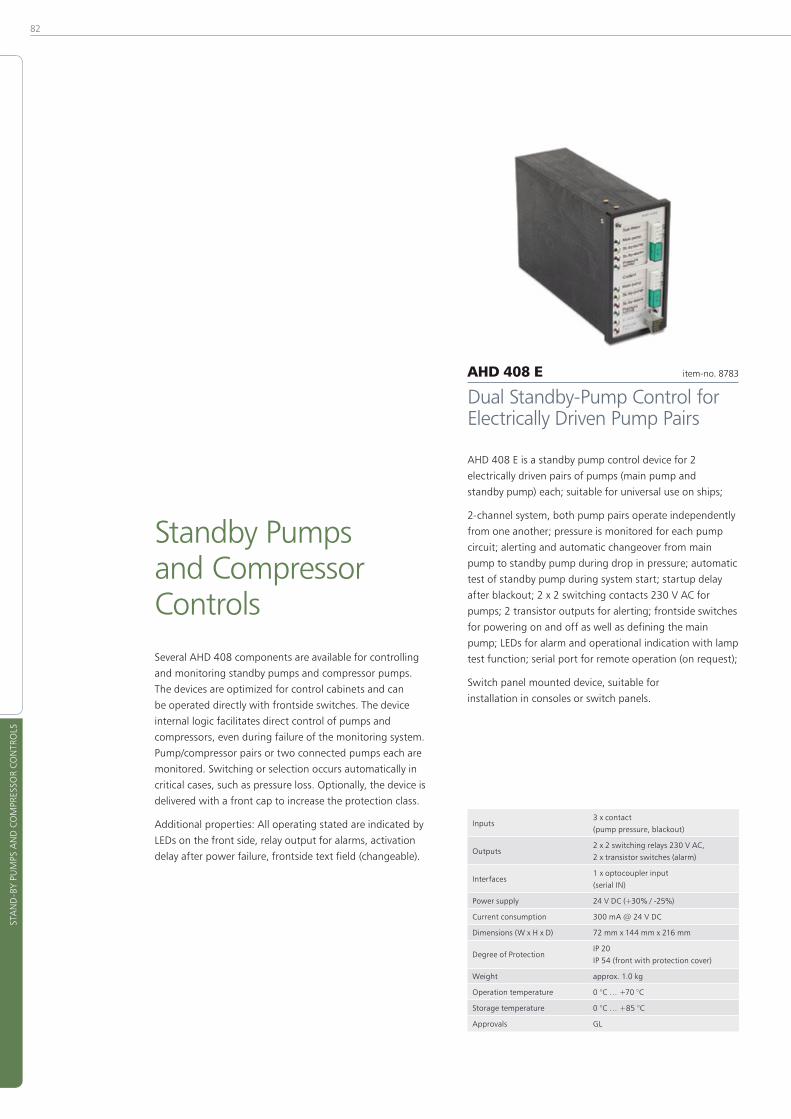
82
STA
ND
-BY
PUM
PS A
ND
CO
MPR
ESSO
R CO
NTR
OLS
Standby Pumps and Compressor ControlsSeveral AHD 408 components are available for controlling
and monitoring standby pumps and compressor pumps�
The devices are optimized for control cabinets and can
be operated directly with frontside switches� The device
internal logic facilitates direct control of pumps and
compressors, even during failure of the monitoring system�
Pump/compressor pairs or two connected pumps each are
monitored� Switching or selection occurs automatically in
critical cases, such as pressure loss� Optionally, the device is
delivered with a front cap to increase the protection class�
Additional properties: All operating stated are indicated by
LEDs on the front side, relay output for alarms, activation
delay after power failure, frontside text field (changeable)�
AHD 408 E item-no� 8783
Dual Standby-Pump Control for Electrically Driven Pump Pairs
AHD 408 E is a standby pump control device for 2
electrically driven pairs of pumps (main pump and
standby pump) each; suitable for universal use on ships;
2-channel system, both pump pairs operate independently
from one another; pressure is monitored for each pump
circuit; alerting and automatic changeover from main
pump to standby pump during drop in pressure; automatic
test of standby pump during system start; startup delay
after blackout; 2 x 2 switching contacts 230 V AC for
pumps; 2 transistor outputs for alerting; frontside switches
for powering on and off as well as defining the main
pump; LEDs for alarm and operational indication with lamp
test function; serial port for remote operation (on request);
Switch panel mounted device, suitable for
installation in consoles or switch panels�
Inputs3 x contact
(pump pressure, blackout)
Outputs2 x 2 switching relays 230 V AC,
2 x transistor switches (alarm)
Interfaces1 x optocoupler input
(serial IN)
Power supply 24 V DC (+30% / -25%)
Current consumption 300 mA @ 24 V DC
Dimensions (W x H x D) 72 mm x 144 mm x 216 mm
Degree of ProtectionIP 20
IP 54 (front with protection cover)
Weight approx� 1�0 kg
Operation temperature 0 °C … +70 °C
Storage temperature 0 °C … +85 °C
Approvals GL
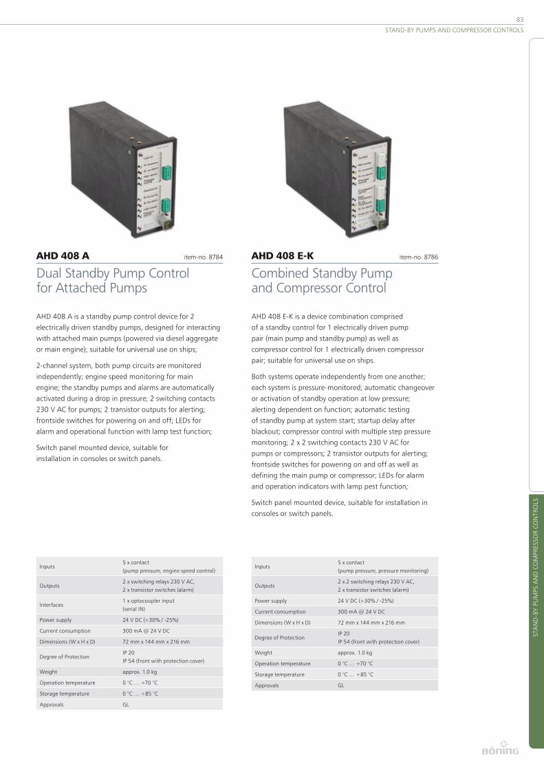
83
STA
ND
-BY
PUM
PS A
ND
CO
MPR
ESSO
R CO
NTR
OLS
STAND-BY PUMPS AND COMPRESSOR CONTROLS
AHD 408 A item-no� 8784
Dual Standby Pump Control for Attached Pumps
AHD 408 A is a standby pump control device for 2
electrically driven standby pumps, designed for interacting
with attached main pumps (powered via diesel aggregate
or main engine); suitable for universal use on ships;
2-channel system, both pump circuits are monitored
independently; engine speed monitoring for main
engine; the standby pumps and alarms are automatically
activated during a drop in pressure; 2 switching contacts
230 V AC for pumps; 2 transistor outputs for alerting;
frontside switches for powering on and off; LEDs for
alarm and operational function with lamp test function;
Switch panel mounted device, suitable for
installation in consoles or switch panels�
Inputs5 x contact
(pump pressure, engine speed control)
Outputs2 x switching relays 230 V AC,
2 x transistor switches (alarm)
Interfaces1 x optocoupler input
(serial IN)
Power supply 24 V DC (+30% / -25%)
Current consumption 300 mA @ 24 V DC
Dimensions (W x H x D) 72 mm x 144 mm x 216 mm
Degree of ProtectionIP 20
IP 54 (front with protection cover)
Weight approx� 1�0 kg
Operation temperature 0 °C … +70 °C
Storage temperature 0 °C … +85 °C
Approvals GL
AHD 408 E-K item-no� 8786
Combined Standby Pump and Compressor Control
AHD 408 E-K is a device combination comprised
of a standby control for 1 electrically driven pump
pair (main pump and standby pump) as well as
compressor control for 1 electrically driven compressor
pair; suitable for universal use on ships�
Both systems operate independently from one another;
each system is pressure-monitored; automatic changeover
or activation of standby operation at low pressure;
alerting dependent on function; automatic testing
of standby pump at system start; startup delay after
blackout; compressor control with multiple step pressure
monitoring; 2 x 2 switching contacts 230 V AC for
pumps or compressors; 2 transistor outputs for alerting;
frontside switches for powering on and off as well as
defining the main pump or compressor; LEDs for alarm
and operation indicators with lamp pest function;
Switch panel mounted device, suitable for installation in
consoles or switch panels�
Inputs5 x contact
(pump pressure, pressure monitoring)
Outputs2 x 2 switching relays 230 V AC,
2 x transistor switches (alarm)
Power supply 24 V DC (+30% / -25%)
Current consumption 300 mA @ 24 V DC
Dimensions (W x H x D) 72 mm x 144 mm x 216 mm
Degree of ProtectionIP 20
IP 54 (front with protection cover)
Weight approx� 1�0 kg
Operation temperature 0 °C … +70 °C
Storage temperature 0 °C … +85 °C
Approvals GL

84
BOW
TH
RUST
ER C
ON
TRO
L
Bow Thruster ControlThe components AHD 501 and AHD 502 allow
for full control and monitoring of a bow thruster
with 3-phase asynchronous motor (slip-ring rotor)
with a fixed propeller� In addition to reversing the
contactor in both directions, the power stages 70 %,
85 %, and 100 % can be selected directly, while the
auxiliary stages prevent excessive start voltages�
The central unit AHD 501 is installed in the drive section
or the control cabinet of the bow thruster� The unit
monitors all feedback messages, captures all current
and temperature sensors, and processes the commu-
nication with the control units AHD 502� All control
commands are captured by the central unit via a CAN
bus� All relevant measured data and feedback messages
are displayed on the helms; faults and critical states
are monitored� Depending on the malfunction or the
degree of overload, the system responds by reducing
the power or initiating a stop� Additional properties:
fan speed control, oil level monitoring, control current
monitoring, 2-stage capture of engine current, input for
direct locking of the 100 % stage, diagnostic USB port�
The control unit AHD 502 allows for convenient
monitoring and control of the bow thruster� Up to 3
identical units, which are generally installed on the
bridge and both wing control helms (Bb� and Stb�),
can be used� The control unit is optimized for flush
mounting� Each stage can be accessed directly from
the control buttons� Keys for controlling the displays,
quit, and emergency stop are also present�
The integrated 3�5” color display is dimmed automatically
and presents all important operating states, such as
current consumption, stage, and direction, in a clearly
viewable manner� Alarms are reported acoustically and
optically� In addition, there are potential free contacts for
general alarm and connection to an external whistle�
The control units communicate with one another and
the central control unit AHD 501 over separate CAN
networks� Here, all necessary terminating resistors
are already integrated� The cabling effort is signifi-
cantly reduced, compared to traditional systems�
Additional properties: integrated “Power Request”
button for power requests to the power management
system with feedback indicator, port for external
joystick, fault detection and service function for
system states, menu for setting the overcurrent
limits, RS-422 port for accessing a voyage data
recorder according to IEC-61162-1 (proprietary)�

85
BOW
TH
RUST
ER C
ON
TRO
L
BOW THRUSTER CONTROL
AHD 501 item-no� 12028
Electr� Bow Thruster Control – Central Unit
AHD 501 is a central bow thruster control unit for
electrically driven bow thrusters with a 3-phase
asynchronous motor (slip-ring rotor) and attached fixed
propeller� In conjunction with the display and control unit
AHD 502 (see item-no� 12369), this provides a complete
package solution which fully covers all requirements
pertaining to control and monitoring functions�
Direct control of direction, stage, and interstage
contactors including feedback monitoring; control of
the 3 main stages (70 %, 85 %, 100 %) and up to 6
intermediate stages per effective direction; automatic
fan control and monitoring; control of an engine brake;
monitoring of engine current, winding temperatures (in
the engine) and oil level; contactor (circuit breaker) control
voltage check; external locking of the 100 % stage; 13
high load switching outputs for direct contactor and
circuit breaker control; 16 binary and 4 analog inputs
for status feedback, control, and alerting; frontside
LEDs for fault status; CAN communication bus to
control and display units AHD 502; the overall system
is configured via an included software package;
Electronics unit in profile carrier housing, suitable
for carrier rail mounting (TS32/35), for installa-
tion in the bow thruster’s control cabinet�
Inputs16 x optocoupler inputs
(feedback, control, alarm)
Outputs13 x switching outputs
(control contactors)
Interfaces1 x CAN (galvanically isolated),
1 x USB
Power supply 24 V DC (+30% / -25%)
Current consumption 500 mA @ 24 V DC
Dimensions (W x H x D) 216 mm x 126 mm x 64 mm
Degree of Protection IP 20
Weight approx� 0�8 kg
Operation temperature -30 °C … +70 °C
Storage temperature -50 °C … +85 °C
Approvals GL, LR, BV
AHD 502 item-no� 12369
Electr� Bow Thruster Control – Control and Display Unit
AHD 502 is a compact display and control
unit for electrically driven bow thrusters
(control and display unit for AHD 501)�
AHD 502 allows convenient operation of the bow thruster�
Every power stage can be selected directly via command
keys; direction and engine current are continuously
displayed via the integrated 3�5” color display; further,
all available data can be retrieved on various display
pages; during an alarm, an optical and acoustic signal is
given� As a standard, up to 3 control units are installed
(bridge console, nock helms Bb and Stb)� Optionally, a
4th unit can also be installed (see item-no� 14667)�
Integrated emergency stop function; frontside LEDs
for fault status; 3 switching outputs for power
requirement, collective alarm, and horn; monitoring
of power requirement (input for feedback); can be
connected to external joystick (s� item-no� 14023); system
communication via 3x CAN bus, thus simple installation
and minimal cabling effort; integrated RS-422 port
(IEC-61162-1) for activating a data voyage recorder�
Service menu for displaying internal system states (fault
diagnosis), launch alarm memory and programming
functions; local configuration of current thresholds
and other important operational parameters can be
performed directly on the device; diagnosis port for
servicing and configuration via included PC software�
Inputs 1 x optocoupler (Power Ready)
Outputs4 x switching outputs (emergency stop,
Power-Request, common alarm, Horn)
Interfaces
3 x CAN (galvanically isolated),
1 x RS-422 (IEC-61162-1),
1 x serial
Power supply 24 V DC (+30% / -25%)
Current consumption 500 mA @ 24 V DC
Dimensions (W x H x D) 192 mm x 144 mm x 45 mm
Degree of ProtectionIP 56 (front)
IP 20 (rear)
Weight approx� 1�0 kg
Operation temperature -30 °C … +70 °C
Storage temperature -50 °C … +85 °C
Approvals GL, LR, BV

86
DEV
ICE
IND
EX
Device Index
AHD 406-2 ���������������������������������������������������������������������� 81
AHD 408 A ���������������������������������������������������������������������� 83
AHD 408 E ���������������������������������������������������������������������� 82
AHD 408 E-K ������������������������������������������������������������������� 83
AHD 414 A ���������������������������������������������������������������������� 78
AHD 414 �������������������������������������������������������������������������� 78
AHD 430 ������������������������������������������������������������������������� 22
AHD 501 ������������������������������������������������������������������������� 85
AHD 502 ������������������������������������������������������������������������� 85
AHD 504 A ���������������������������������������������������������������������� 76
AHD 504 NG ������������������������������������������������������������������� 77
AHD 514 A ���������������������������������������������������������������������� 75
AHD 514 OP �������������������������������������������������������������������� 76
AHD 514 S ����������������������������������������������������������������������� 75
AHD 650 R ���������������������������������������������������������������������� 25
AHD 651 ������������������������������������������������������������������������� 22
AHD 880 E ���������������������������������������������������������������������� 21
AHD 880 TC �������������������������������������������������������������������� 21
AHD 880 TC G ����������������������������������������������������������������� 20
AHD 882 ������������������������������������������������������������������������� 33
AHD 1110 F ����������������������������������������������������������������������19
AHD 1119 F / AHD 1115 F �������������������������������������������������19
AHD 1119 G / AHD 1115 G ������������������������������������������������18
AHD 1200 ������������������������������������������������������������������������16
AHD 1219 F / AHD 1215 F �������������������������������������������������17
AHD 1219 G / AHD 1215 G �����������������������������������������������15
AHD 1224 G ���������������������������������������������������������������������16
AHD-AMU ����������������������������������������������������������������������� 38
AHD-AO 6 ����������������������������������������������������������������������� 28
AHD-Charting ����������������������������������������������������������������� 37
AHD-CUC ������������������������������������������������������������������������ 32
AHD-DACP ���������������������������������������������������������������������� 48
AHD-DC �������������������������������������������������������������������������� 24
AHD-DC R ����������������������������������������������������������������������� 23
AHD-DEOP �����������������������������������������������������������������������51
AHD-DeviceConfig, AHD-DisplayDesigner ������������������������� 8
AHD-DPS 02 A07 ������������������������������������������������������������ 58
AHD-DPS 02 B14 ������������������������������������������������������������� 56
AHD-DPS 02 BS ��������������������������������������������������������������� 56
AHD-DPS 02 G14������������������������������������������������������������� 55
AHD-DPS 02 GC �������������������������������������������������������������� 57
AHD-DPS 02 Selector Switch ������������������������������������������� 57
AHD-DPU 9 ��������������������������������������������������������������������� 29
AHD-DRM R �������������������������������������������������������������������� 25
AHD-DRM T �������������������������������������������������������������������� 24
AHD-EOP Adapter ����������������������������������������������������������� 52
AHD-EOP ��������������������������������������������������������������������������51
AHD-EOP K I �������������������������������������������������������������������� 52
AHD-EST V2 �������������������������������������������������������������������� 53
AHD-GAP F ��������������������������������������������������������������������� 46
AHD-IAMCS �������������������������������������������������������������������� 37
AHD-ORP ������������������������������������������������������������������������ 53
AHD-POS 10 �������������������������������������������������������������������� 58
AHD-PS 15 ���������������������������������������������������������������������� 27
AHD-PS 15 B ������������������������������������������������������������������� 81
AHD-PS 30 ���������������������������������������������������������������������� 27
AHD-PS 47 ���������������������������������������������������������������������� 27
AHD-R 101 ���������������������������������������������������������������������� 30
AHD-RB 6 ������������������������������������������������������������������������ 32
AHD-S 201 ���������������������������������������������������������������������� 40
AHD-SAS 15 �������������������������������������������������������������������� 26
AHD-SL ���������������������������������������������������������������������������� 47
AHD-SLP �������������������������������������������������������������������������� 47
AHD-SW I ������������������������������������������������������������������������ 39
AHD-TCS A ���������������������������������������������������������������������� 71
AHD-TCS HYD ����������������������������������������������������������������� 72
AHD-TCS INCL ����������������������������������������������������������������� 71
AHD-TCS OP A ����������������������������������������������������������������� 71
AHD-TP 2 ������������������������������������������������������������������������ 46
AHD-UCC ������������������������������������������������������������������������ 28
AHD-UIC ������������������������������������������������������������������������� 31
AHD-VC 711 �������������������������������������������������������������������� 64
AHD-VC 720IR ����������������������������������������������������������������� 64
AHD-VC 731 �������������������������������������������������������������������� 63
AHD-VC 740 �������������������������������������������������������������������� 65
AHD-VC 741 �������������������������������������������������������������������� 65
AHD-VC 753 �������������������������������������������������������������������� 63
AHD-VCP ������������������������������������������������������������������������� 62
AHD-VCS Q4-1 ���������������������������������������������������������������� 61
AHD-VC VR8/16 �������������������������������������������������������������� 62
AHD-VDCU 16/16 ������������������������������������������������������������ 61
AHD-VSC C ���������������������������������������������������������������������� 66
AHD-VSC CB �������������������������������������������������������������������� 66
AHD-VSC CF �������������������������������������������������������������������� 66
AHD-VSC CFV ������������������������������������������������������������������ 66
AHD-VSC QC ������������������������������������������������������������������� 66
AHD-WAOP ��������������������������������������������������������������������� 45
AHD-WAOP K ������������������������������������������������������������������ 45
AHD-WNA ����������������������������������������������������������������������� 35
AHD-WNL ����������������������������������������������������������������������� 36
AHD-WOP ����������������������������������������������������������������������� 48
DeviceNet �������������������������������������������������������������������������41
Draghetti Marine Division Trim Tabs �������������������������������� 72
Draghetti Marine Division Hydraulic Cylinders ����������������� 72
HM-Series, FLIR Systems �������������������������������������������������� 67
M-Series, FLIR Systems ���������������������������������������������������� 68
MU/MV-Series, FLIR Systems ������������������������������������������� 68
PE4000WE ��������������������������������������������������������������������� 40
Voyager II, FLIR Systems �������������������������������������������������� 69
Texts and illustrations in this catalog are non-binding�
Changes may be made due to technical improvements�
©2014 Böning Automationstechnologie GmbH & Co� KG

87
CON
TAC
T IN
FORM
ATI
ON
CONTACT INFORMATION
Contact Information
Headquarter Böning Automationstechnologie GmbH & Co. KG Am Steenöver 4
27777 Ganderkesee
Germany
Phone: +49 4221 9475-0
Fax: +49 4221 9475-22
E-Mail: info@boening�com
Web: www�boening�com
ItaliaBöning Italia srl. Sales & Service Corso Genova, 191
16033 Lavagna, GE
Italy
Phone: +39 0185 177 0876
Fax: +39 0185 177 0876
E-Mail: italia@boening�com
Sales and Service Partners For a list of our partners please visit our website
www�boening�com
BrazilBöning Imp. e Com. de Equip. Náuticos Ltda. Rua Ulysses Pedroso de Oliveira Filho, 469
Valinhos-SP – CEP 13270-393
Brasil
Phone: +55 19 3849-5942
Fax: +55 19 3849-5942
E-Mail: luiz�barbarini@boening�com
Web: www�boening�com�br
CroatiaBöning d.o.o. Razvoj, proizvodnja i servisiranje elektroničke opreme
Prve Primorske čete 64A
HR-22211 Vodice
Croatia
Phone: +385 22 440693
E-Mail: marinko�vukancic@boening�com
Visit our website for detailed information on our
systems and products, latest news, exhibition dates
and much more:
www.boening.com
www.boening.com
V 1
�0 2
014
-05
ScM
i-100
4
Böning Automationstechnologie GmbH & Co. KG
Am Steenöver 4 27777 Ganderkesee Germany
Phone: +49 4221 9475 0 Fax: +49 4221 9475 22 E-Mail: info@boening�com