bodywork fitting guide - renault...
TRANSCRIPT

BODYWORK FITTING GUIDE
1/398 English edition
06/2007
Recommendation "free space to the rear of the cab for positioning the crane feet"
© RENAULT TRUCKS – 2007 1/37 14/10/2008
© RENAULT TRUCKS – 2007 2/37 14/10/2008
TABLE OF CONTENTS
1. Change in position of SCR "Selective Catalytic Reduction" silencer
- 1.1. Introduction 3/37 - 1.2. Reminder (refer to « Vehicle Servicing Handbook ») 4/37 - 1.3. Types of SCR silencer outlets 7/37 - 1.4. Replacement of SCR silencer 10/37 - 1.5. Change in position of SCR silencer 11/37 - 1.6. Modifications to tube before the SCR silencer 13/37 - 1.7. Heat shielding 20/37 - 1.8. Modifications to tube after the SCR silencer 22/37 - 1.9. Table of wiring harnesses 29/37
2. Change in position of air filter
- 2.1. Introduction 31/37 - 2.2. Generalities 31/37 - 2.3. Change in position of vertical air filter on wheelarch 33/37 - 2.4. Replacement of water drainage valve 37/37

1. Change in position of SCR "Selective Catalytic Reduction" silencer
1.1. Introduction Vehicles concerned:
- RENAULT PREMIUM (Distribution, Long Distance and Lander) Euro 4 DXi 11 - RENAULT KERAX Euro 4 DXi 11 - RENAULT MAGNUM Euro 4 DXi 13
Renault Trucks vehicles are marketed after the completion of confirmed technical designwork and validation trials, bearing in mind the different laws, regulations, standards…
The bodybuilder must comply with:
- Different European and/or destination countries' laws and regulations governing the driving and building of vehicles.
- Stipulations of the Highway Code and its various amendments and appendices.
- Different regulations and standards governing toad traffic in force in the destination countries.
Any modification not described in the present document or change in position of parts or elements making up the vehicle must be covered by a technical agreement issued by the Renault Trucks Products Application Department.
Note: For any further information, consult the Renault Trucks Product Applications Department.
Note: Parts to be used are available from the Renault Trucks Spare Parts Warehouse.
WARNING For the crane pre-arrangement and/or vehicles fitted with landing legs in conjunction with air suspension systems, it is recommended to use the suspension inhibition feature (refer to Bodywork Fitting Guide, "Electrics" chapter, "Supplementary features" section) in order to avoid the feedback of faults from the suspension management electronic control box (ECS).
Important: In this document, all dimensions are given in millimetres.
© RENAULT TRUCKS – 2007 3/37 14/10/2008

1.2. Reminder (refer to « Vehicle Servicing Handbook »)
G - “INFORMATION” warning light: indicating that a new message has appeared on the multi-function information display (L)
I - "SERVICE" warning light: Make your way to the nearest RENAULT TRUCKS service station N - Pollution control system fault warning pictogram
Note: For a description of the warning lights, see the «instrument panel» section below.
If the level is correct, warning pictogram (2) is displayed and bargraph (1) shows the AdBlue level. If the level is too low, warning light (AA) comes on. (refer to "Vehicle Servicing Handbook")
Note: If there is any AdBlue level sensor fault, bargraph (1) disappears.
© RENAULT TRUCKS – 2007 4/37 14/10/2008

If the vehicle is used with the AdBlue reservoir empty:
– Warning pictogram (N) flashes. – Warning light (G) comes on. – Warning pictogram (G79) - (1) and a related text (2) appear on the multi-function information display (L).
Engine pollution control is no longer assured, so an engine torque reduction phase will be applied the next time the vehicle is stationary.
Note: When warning pictogram (N) flashes, it means that the next time the engine is started, the fault will be
memorized and cannot be erased for 400 days. It can be consulted at any moment by the police. In the event of detection of insufficient pollution control by the system (NOx level above 7g/kWh):
– Warning pictogram (N) flashes. – Warning light (I) comes on. – Warning pictogram (G12) - (1) and a related text (2) appear on multi-function information display (L).
Make your way to a RENAULT TRUCKS service station.
Note: If engine pollution control is no longer assured, a 40% reduction in engine torque (25% for certain vehicles) will be applied the next time the vehicle is stationary. Make your way to a RENAULT TRUCKS service station.
Note: When warning pictogram (N) flashes, it means that the next time the engine is started, the fault will be memorized and cannot be erased for 400 days. It can be consulted at any moment by the police.
© RENAULT TRUCKS – 2007 5/37 14/10/2008

In the event of failure of the exhaust gases analysis sensor:
– Warning light (I) comes on and warning pictogram (N) is displayed. – Warning pictogram (G12) - (1), a related text (2) and a countdown (3) starting at 50 hours, appear on the multi-function information display (L).
Note: The countdown (3) indicates the time remaining before application of engine torque reduction.
Make your way to a RENAULT TRUCKS service station. Warning: The use of AdBlue is vital both for correct running of the vehicle and for compliance with the regulations in force. If you do not use AdBlue, it may be considered as an offence.
© RENAULT TRUCKS – 2007 6/37 14/10/2008
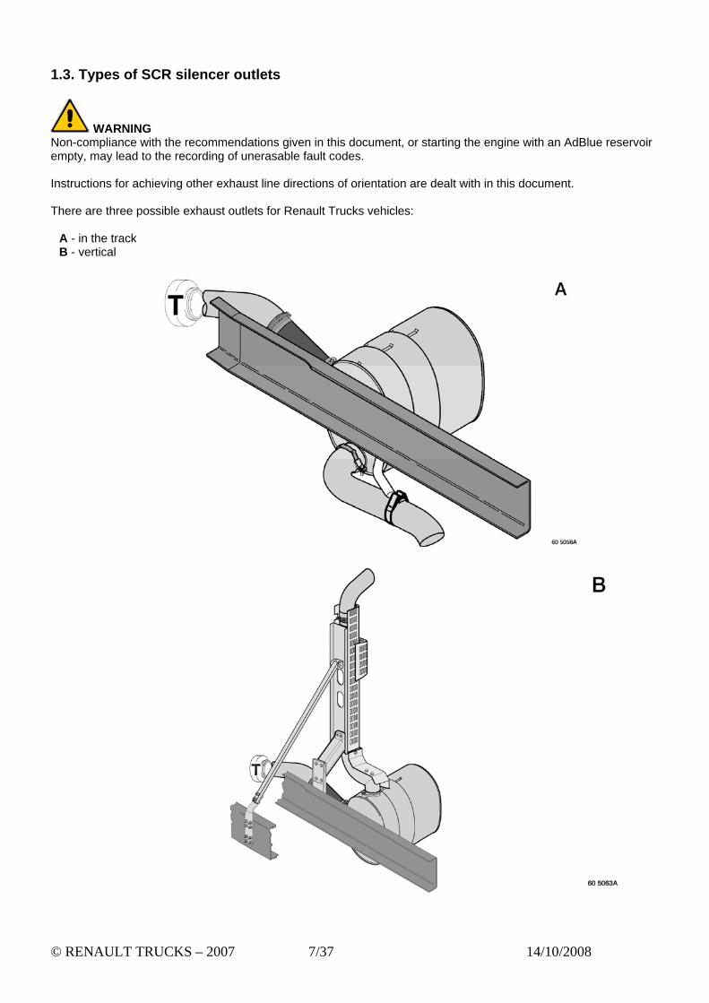
1.3. Types of SCR silencer outlets
WARNING Non-compliance with the recommendations given in this document, or starting the engine with an AdBlue reservoir empty, may lead to the recording of unerasable fault codes. Instructions for achieving other exhaust line directions of orientation are dealt with in this document.
There are three possible exhaust outlets for Renault Trucks vehicles:
A - in the track B - vertical
© RENAULT TRUCKS – 2007 7/37 14/10/2008

WARNING The position of an SCR silencer with exhaust outlet on the left cannot be changed. If your vehicle is equipped with this configuration, it is essential to install an outlet in the track.
C – on the left
© RENAULT TRUCKS – 2007 8/37 14/10/2008

Vehicles equipped with DXi 11 engine
(1) - horizontal outlet (RENAULT PREMIUM, RENAULT KERAX) (2) - vertical outlets:
(2a) - oblique outlet with day cab and global cab, except for 8x4 (2b) – straight outlet with sleeper cab, except for 8x4, day cab and global cab for 8x4
Vehicles equipped with DXi 13 engine
(1) - horizontal outlet (RENAULT MAGNUM)
Silencer weights:
- 71 kg for Euro 4 - 77 kg for Euro 5 incentive
WARNING The heavy weight of catalytic converters requires the use of lifting tackle. Depending on vehicle configuration and workshop tools, use appropriate lifting tackle (handling trolley, strap(s)…).
© RENAULT TRUCKS – 2007 9/37 14/10/2008

1.4. Replacement of SCR silencer If the SCR silencer is replaced, the new SCR silencer must be compatible with the vehicle’s engine and feature the same exhaust emissions level as the original SCR silencer (Euro 4 and Euro 5 incentive SCR "Selective Catalytic Reduction"). Heat shields and other parts must be fitted to the SCR silencer as on the original installation. The SCR silencer must always be supported by its original brackets:
A - SCR silencer bracket, front wing bracket and securing straps B - anchorage, bracket and securing straps
© RENAULT TRUCKS – 2007 10/37 14/10/2008

1.5. Change in position of SCR silencer
Reminder:
x – change in position towards the rear y – change in position towards the interior z – change in position of towards the bottom
WARNING Any person carrying out work is responsible for his own services in terms of warranty and liability, including damage caused by the work and/or equipment installed on the vehicle or on the basic product.
WARNING Any failure to observe these recommendations shall be considered as breach of the same rules and will relieve RENAULT TRUCKS from its responsibility in the event of any damage connected directly or indirectly with such non-observation.
The requirements below must be obeyed in sequence in order to comply with Euro 4 and Euro 5 incentive pollution control standards, for meeting the correct operating temperatures and not exceeding the maximum authorized exhaust line head loss.
Note: -The installations recommended in this manual are covered by engine type approvals.
- The maximum temperature is 450°C at the exhaust outlet. - Ensure that the exhaust outlet does not damage or adversely affect other on-vehicle components. - Do not modify existing wiring harnesses – replace if necessary (refer to "Wiring harnesses table").
For any further information on wiring and cabling, please contact the Renault Trucks Product Applications Department. Euro 4 vehicles The position of the SCR silencer can be moved to the rear of the sidemembers by a maximum of 2000 mm, measured from its initial position (outlet in the track (1) and vertical outlet (2)).
© RENAULT TRUCKS – 2007 11/37 14/10/2008

Euro 5 incentive vehicles The position of the SCR silencer can be moved to the rear of the sidemembers by a maximum of 2000 mm for the outlet in the track (1) and 1200 mm for the vertical outlet (2), measured from its initial position.
WARNING If the change in position of the SCR silencer is recommended along axis (x) only, do not modify the vertical orientation of the silencer, i.e. keep the same lines of drillings. If possible, keep the original SCR silencer brackets supplied with the vehicle.
WARNING If the change in position of the SCR silencer is recommended along the three axes (x, y, z), the modifications made to the SCR silencer bracket and its fastenings, together with the reliability of assembly, are the equipment manufacturer’s responsibility. This is also applicable if the change in position takes place along axis (x) involving modification to the SCR silencer brackets.
© RENAULT TRUCKS – 2007 12/37 14/10/2008

© RENAULT TRUCKS – 2007 13/37 14/10/2008
1.6. Modifications to tube before the SCR silencer Euro 4 vehicles
Change in position dimension (mm)
0 to 200 200 to 250 250 to 500 500 to 650 650 to 2000 2000*
8x4 axle spread
Change in position of SCR silencer along 3 axes (x, y, z), arrangement of turbocharger outlet and silencer inlet tubes
Technical impossibility
Addition of a second flexible pipe and intermediate tube (C)
Other axle
spreads
Change in position of SCR silencer along 3 axes (x, y, z), arrangement of turbocharger outlet and silencer inlet tubes
Change in position of SCR silencer with insertion of a fabricated interface tube (A) between the flexible pipe and the silencer Between 450 and 500 mm, possibility of installing a cranked tube (B)
Technical impossibility
Addition of a second flexible pipe and intermediate tube (C)
-
* just behind the second axle
Euro 5 incentive vehicles
Outlet in the track
Change in position dimension (mm)
0 to 200 200 to 250 250 to 500 500 to 650 650 to 2000 2000*
8x4 axle spread
Change in position of SCR silencer along 3 axes (x, y, z), arrangement of turbocharger outlet and silencer inlet tubes
Technical impossibility
Addition of a second flexible pipe and intermediate tube (C)
Other axle
spreads
Change in position of SCR silencer along 3 axes (x, y, z), arrangement of turbocharger outlet and silencer inlet tubes
Change in position of SCR silencer with insertion of a fabricated interface tube (A) between the flexible pipe and the silencer Between 450 and 500 mm, possibility of installing a cranked tube (B)
Technical impossibility
Addition of a second flexible pipe and intermediate tube (C)
-
* just behind the second axle

Vertical outlet
Change in position value (mm)
0 to 200 200 to 250 250 to 500 500 to 650 650 to 1200
8x4 axle spread
Change in position of SCR silencer along 3 axes (x, y, z), arrangement of turbocharger outlet and silencer inlet tubes Reminder: All the parts in the new assembly are the equipment manufacturer’s responsibility (reliability, proximity, gastight seal…).
Technical impossibility
Other axle
spreads
Change in position of SCR silencer along 3 axes (x, y, z), arrangement of turbocharger outlet and silencer inlet tubes Reminder: All the parts in the new assembly are the equipment manufacturer’s responsibility (reliability, proximity, gastight seal…).
Change in position of SCR silencer with insertion of a fabricated interface tube (A) between the flexible pipe and the silencer Between 450 and 500 mm, possibility of installing a cranked tube (B)
Technical impossibility
Addition of a second flexible pipe and intermediate tube (C)
© RENAULT TRUCKS – 2007 14/37 14/10/2008

WARNING
- It is essential to comply with the engine outlet / SCR silencer inlet alignment so that the flexible link-up pipe (1) is perfectly straight.
- For a change in position of 0 to 250 mm, it is necessary to modify the SCR silencer bracket as without modification, it cannot be repositioned because of the spring hanger, so it is necessary to fit an intermediate part between the bracket and the SCR silencer to ensure the changes in position along the x, y, z axes while complying with the ground clearance and the overall length of the vehicle.
- Since the tube or flexible pipe can pass through the wheelarch bracket, modification of the bracket must be avoided - if not, it is essential to reinforce the bracket.
RENAULT KERAX vehicle This vehicle is type approved as "Off-road" so when laden, it is essential to observe:
Z-axis - ground clearance 300 mm minimum Y-axis - 40 mm minimum change in position over overall vehicle length
Note: For any further information, consult the Renault Trucks Product Applications Department.
Change in position with a fabricated tube (A) between 250 and 500 mm
© RENAULT TRUCKS – 2007 15/37 14/10/2008

The fabricated tube must be in at least 5 sections.
Change in position of a cranked tube (B) between 450 and 500 mm
© RENAULT TRUCKS – 2007 16/37 14/10/2008

Change in position of intermediate tube and second flexible pipe (C) between 650 and 2000 mm
T – turbocharger outlet
To change the position of the SCR silencer (A), it is necessary to extend the exhaust pipe (D to E) by meeting the requirements below (see illustrations hereafter).
Tube characteristics Material Stainless steel, minimum quality meeting standard ISO 683/13 19861Ti Tube diameter 127 mm Tube thickness 2 mm
The following requirements must be met in order to form the bends on the tube between (D) and (E) before the SCR silencer (A).
Tube bending characteristics
Maximum number of bends 3 Total angle of curvature 190° Recommended radius (r) measured in centre of tube 170 mm Minimum radius (r) measured in centre of tube 140 mm
All the bends added to the tube must be tangential (gentle bends). The tubes must be assembled so as to ensure a gastight seal (clamps…) whether they be bent or fabricated.
© RENAULT TRUCKS – 2007 17/37 14/10/2008

The modified tube (D to E) must be correctly held by brackets (1) to avoid damaging the turbocharger outlet (T) and the SCR silencer outlet (A). These brackets, together with their reliability of assembly, are the equipment manufacturer’s responsibility.
For a modified tube up to 500 mm in length, provide one bracket (1) – beyond this, provide one bracket approximately every 400 mm.
The flexible pipe (B) originally fitted to the turbocharger outlet must remain in place. If the distance from the flexible pipe after the turbocharger outlet (D) to the outlet (F) of the SCR silencer (A) exceeds 500 mm, another flexible pipe (C), with the same characteristics as (B), must be added before the outlet of the SCR silencer (A).
WARNING Reminder: Any change in position of the SCR silencer (A) is forbidden between 500 and 650 mm.
T – turbocharger outlet
The flexible pipe (B and C) must be fitted straight (without bends) inside its nominal length.
Note: Parts to be used are available from the Renault Trucks Spare Parts Warehouse.
© RENAULT TRUCKS – 2007 18/37 14/10/2008
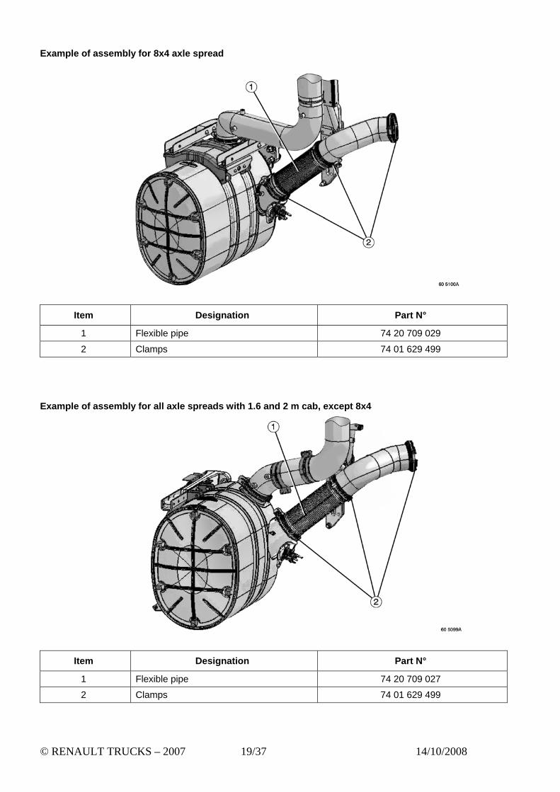
Example of assembly for 8x4 axle spread
Item Designation Part N°
1 Flexible pipe 74 20 709 029
2 Clamps 74 01 629 499
Example of assembly for all axle spreads with 1.6 and 2 m cab, except 8x4
Item Designation Part N°
1 Flexible pipe 74 20 709 027
2 Clamps 74 01 629 499
© RENAULT TRUCKS – 2007 19/37 14/10/2008

1.7. Heat shielding
The exhaust pipe (D to E) must be heat shielded (with the exclusion of flexible pipes B and C).
T – turbocharger outlet
The heat shielding must be non-inflammable, non-toxic and its characteristics must be greater than or equal to the values below:
Heat shielding conditions (minimum values) Operating temperature 700°C Density 130 kg/m Thickness 20 mm (2 x 10 mm layers) Guard plate (stainless steel) 0.2 mm approx.
Efficient, gastight heat shielding must be fastened correctly over the entire surface of the tube and at both ends in order to give maximum protection. The heat shielding also provides protection against dirt and mechanical wear.
Note: The heat shielding must not be compressed.
WARNING When changing the position of the SCR silencer, it is essential to protect the AdBlue temperature sensor and injector, as well as all components in the exhaust line that are sensitive to high temperatures (450°C), with heat shields. Heat shields and the reliability of their fastenings are the equipment manufacturer’s responsibility depending on the specific features of the vehicle concerned.
© RENAULT TRUCKS – 2007 20/37 14/10/2008

WARNING When changing the position of the SCR silencer (A) before the second axle, it is essential to keep the heat shield and be sure of leaving enough space to prevent any contact between the wheelarch (B) and the silencer (A).
WARNING When changing the position of the SCR silencer (A) behind the second axle, if the second flexible pipe (B) is located in proximity to the braking circuit (C), the suspension shock absorber bush (D) or any wiring harness, it is essential to protect the latter components by installing a heat shield (1). This heat shield can be identical to the heat shield (2) fitted to the flexible pipe, but under no circumstances should it be fitted to the flexible pipe.
© RENAULT TRUCKS – 2007 21/37 14/10/2008
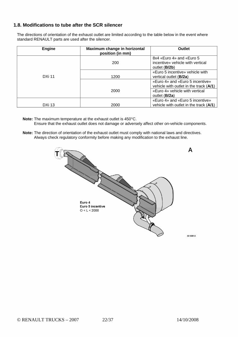
1.8. Modifications to tube after the SCR silencer
The directions of orientation of the exhaust outlet are limited according to the table below in the event where standard RENAULT parts are used after the silencer.
Engine Maximum change in horizontal
position (in mm) Outlet
200
8x4 «Euro 4» and «Euro 5 incentive» vehicle with vertical outlet (B/2b)
1200
«Euro 5 incentive» vehicle with vertical outlet (B/2a) «Euro 4» and «Euro 5 incentive» vehicle with outlet in the track (A/1)
DXi 11
2000 «Euro 4» vehicle with vertical outlet (B/2a)
DXi 13
2000
«Euro 4» and «Euro 5 incentive» vehicle with outlet in the track (A/1)
Note: The maximum temperature at the exhaust outlet is 450°C. Ensure that the exhaust outlet does not damage or adversely affect other on-vehicle components.
Note: The direction of orientation of the exhaust outlet must comply with national laws and directives.
Always check regulatory conformity before making any modification to the exhaust line.
© RENAULT TRUCKS – 2007 22/37 14/10/2008

Note: For any further information, consult contact the Renault Trucks Product Applications Department.
Note: Parts to be used are available from the Renault Trucks Spare Parts Warehouse.
WARNING Any change in position of the SCR silencer in the configuration (C) hereafter is strictly forbidden.
© RENAULT TRUCKS – 2007 23/37 14/10/2008

(1) - horizontal outlet (in the track) (2a) - oblique vertical outlet (2b) - straight vertical outlet
Standard Renault Trucks parts for outlets in the track (1) fulfil the maximum authorized exhaust line head loss criteria. Parts manufactured by the equipment manufacturer for vertical outlets (2a) and (2b) must fulfil the maximum authorized exhaust line head loss criteria.
In the event where such standard Renault Trucks parts are not used, the following conditions must be met:
Tube characteristics
Material Stainless steel, minimum quality meeting standard ISO 683/13 19861Ti Tube outside diameter 127 mm Tube thickness 2 mm
The following requirements must be met in order to form the bends on the tube after the SCR silencer (A).
Tube bending characteristics
Maximum number of bends 3 Total angle of curvature 190° Recommended radius (r) measured in centre of tube 170 mm Minimum radius (r) measured in centre of tube 140 mm
All the bends added to the tube must be tangential (gentle bends). The tubes must be assembled so as to ensure a gastight seal.
© RENAULT TRUCKS – 2007 24/37 14/10/2008

Note: Parts to be used are available from the Renault Trucks Spare Parts Warehouse. Example of assembly for 8x4 axle spread
Item Designation Part N°
1 Flexible pipe 74 20 442 246
2 Clamps 74 20 455 908
3 Clamp 74 01 629 499
© RENAULT TRUCKS – 2007 25/37 14/10/2008

Example of assembly for all axle spreads with 1.6 and 2 m cab, except 8x4
Item Designation Part N°
1 Flexible pipe 74 20 442 245
2 Clamps 74 20 455 908
3 Clamp 74 01 629 499
© RENAULT TRUCKS – 2007 26/37 14/10/2008

Example of assembly for all axle spreads with 2 m cab, except 8x4
Item Designation Part N°
1 Flexible pipe 74 20 442 245
2 Clamps 74 20 455 908
3 Clamp 74 01 629 499
© RENAULT TRUCKS – 2007 27/37 14/10/2008

Example of assembly for all axle spreads with 2.2 m cab, except 8x4
Item Designation Part N°
1 Flexible pipe 74 20 442 246
2 Clamps 74 20 455 908
3 Clamp 74 01 629 499
© RENAULT TRUCKS – 2007 28/37 14/10/2008

1.9. Table of wiring harnesses When you change the position of an SCR silencer, change the position of related sensors or, if necessary, it is possible to replace the original wiring harnesses with one of the two wiring harnesses below. (1) - 2-way DIN – Temperature sensor after catalytic converter (B98) (2) - 4-way BDK – CAN NOx sensor (B96)
Wiring harness (1)
Premium Long Distance DXi 11 Premium Distribution DXi 11 Premium Lander DXi 11 Kerax DXi 11 Magnum DXi 13
74 21 067 376
A – Exhaust and AdBlue reservoir:
- Silencer temperature sensor Before catalytic converter: Xa/X1 = 280 mm After catalytic converter: Xa/X2 = 700 mm
- NOx metering unit relay: Xa/X3 = 1060 mm - NOx reservoir heating relay: Xa/X4 = 1330 mm - NOx reservoir level and temperature sensor: Xa/X5 = 4280 mm
B – AdBlue pump:
- NDS gauging unit: Xb/X1 = 310 mm - NOx heater: Xb/X2 = 750 mm - NOx pump filter heater: Xb/X3 = 730 mm - AdBlue assembly interface: Xb/X4 = 3090 mm
© RENAULT TRUCKS – 2007 29/37 14/10/2008

Wiring harness (2)
Premium Long Distance DXi 11 Premium Distribution DXi 11 Premium Lander DXi 11 Kerax DXi 11 Magnum DXi 13
74 21 069 092
Note: These parts are available from the Renault Trucks Spare Parts Warehouse
C – Exhaust and AdBlue reservoir:
- Silencer temperature sensor Before catalytic converter: Xc/X1 = 280 mm
- AdBlue metering unit relay Xc/X2 = 1060 mm - NOx sensor: Xc/X3 = 1080mm - AdBlue reservoir heating relay: Xc/X4 = 1330 mm - AdBlue reservoir level and temperature sensor: Xc/X5 = 4280 mm
B – AdBlue pump:
- NDS gauging unit: Xb/X1 = 310 mm - AdBlue heater: Xb/X2 = 750 mm - AdBlue pump filter heater: Xb/X3 = 730 mm - AdBlue assembly interface: Xb/X4 = 3090 mm
© RENAULT TRUCKS – 2007 30/37 14/10/2008

2. Change in position of air filter
2.1. Introduction Vehicles concerned:
- RENAULT KERAX DXi 11 Euro 4 - RENAULT PREMIUM LANDER DXi 11 Euro 4
Equipped with a day cab. All wheelbases. Important: The filtration levels for which a change in position is possible are standard levels 1, 1+, 2
(refer to Bodywork Fitting Guide, "Assembly of equipment to chassis" chapter, "Assembly of specific equipment" section.
WARNING Any change in position of the reinforced version of the air filter (with a prefiltration system) is forbidden. 2.2. Generalities
© RENAULT TRUCKS – 2007 31/37 14/10/2008

1 – Rain cap (Part N° 0024558052), adaptation duct (Part N° 50 10 496 836), one clamp (Part N° 50 10 571 655)
and one clamp (Part N° 50 10 571 721) 2 – Two securing straps (Part N° 74 20 798 021 as standard) 3 – Filter outlet elbow (Part N° 50 10 626 057 as standard), one clamp (Part N° 50 10 571 656 as standard) and
one clamp (Part N° 50 10 571 655) 4 – Elbow to be manufactured locally as per recommendations below and one clamp (Part N° 50 10 571 655) 5 – Air filter bracket (Part N° 74 82 157 882) 6 – Air inlet bellows (Part N° 50 10 599 547 as standard)
© RENAULT TRUCKS – 2007 32/37 14/10/2008
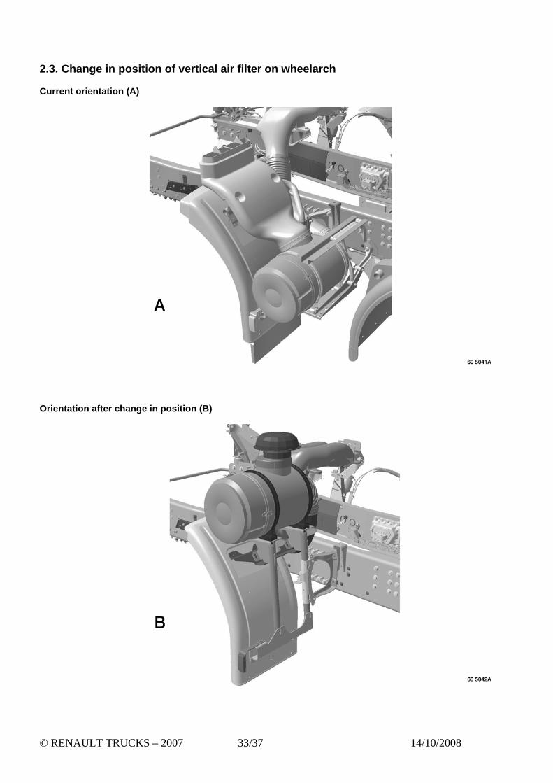
2.3. Change in position of vertical air filter on wheelarch Current orientation (A)
Orientation after change in position (B)
© RENAULT TRUCKS – 2007 33/37 14/10/2008

Longitudinal positioning of the air filter
© RENAULT TRUCKS – 2007 34/37 14/10/2008

4 – Elbow to be manufactured locally as per recommendations below Fabricated stainless steel tube, minimum quality meeting standard ISO 683/13 1986 1 TI. 150 mm outside diameter for connection with filter outlet elbow (3). 153 mm outside diameter for connection with air inlet bellows (6). 35 mm press fit.
Right-angles are forbidden. Keep a constant air channel inside diameter of approximately 150 0/-5 mm.
© RENAULT TRUCKS – 2007 35/37 14/10/2008

Remove the wheelarch bracket fitted as standard. Bracket fastenings (5)
S2 - Use 2 flanged bolts HM 14x40x150 class 10.9 (Part N° 50 03 002 073) and 2 flanged nuts DRH M14 class 10 (Part N° 50 03 033 009).
S4 - Use 2 flanged bolts HM 8x30x125 class 8.8 (Part N° 77 03 002 055). S1 & S3 - Use 2 flanged bolts HM 12x70x125 class 10.9 (Part N° 50 03 002 066) and 2 flanged nuts DRH M12
class 10 (Part N° 50 03 033 012). 8 -Use 2 flanged bolts HM 14x40x150 class 10.9 (Part N° 50 03 002 073) and 2 flanged nuts DRH M14
class 10 (Part N° 50 03 033 009). Tightening torque class III refer to Bodywork Fitting Guide, "Documentary unit introduction" chapter, "Fastening components" section. Air filter to bracket fastenings
Pivot the air filter (7) so that the air inlet allowing installation of the rain cap (1) is in a vertical position.
Fasten the straps (2). A – Apply a force of approximately 20 kg using a cable tie or a screw clamp in the direction of the arrows.
- The straps must be in contact with the air filter, and the filter must not rotate. Tighten the strap securing bolts.
Tighten to torque: 40 N/m +/- 20%
Install the assembly (1) (rain cap, adaptation duct and clamps). Tighten the clamps to torque: 7.5 N/m
Install the elbow (4). B – The equipment manufacturer must provide a fastening for the elbow tube (4) on the air filter bracket (5).
Tighten the clamps to torque: 7.5 N/m
WARNING For correct operation of the engine, it is essential to clean the inside of the elbow tube (4) to get rid of any residue.
© RENAULT TRUCKS – 2007 36/37 14/10/2008

2.4. Replacement of water drainage valve
Caution: The water drainage valve (1) is originally fitted to the bottom of the air filter, but its location has been modified subsequent to a change in position of the filter. Drill one 26 mm diameter hole in the bottom of the filter housing cover. Install a new water drainage valve (Part N° 50 10 315 991). If necessary, replace the old water drainage valve with a rubber plug.
© RENAULT TRUCKS – 2007 37/37 14/10/2008