bmw x-6 battery ride-on
TRANSCRIPT
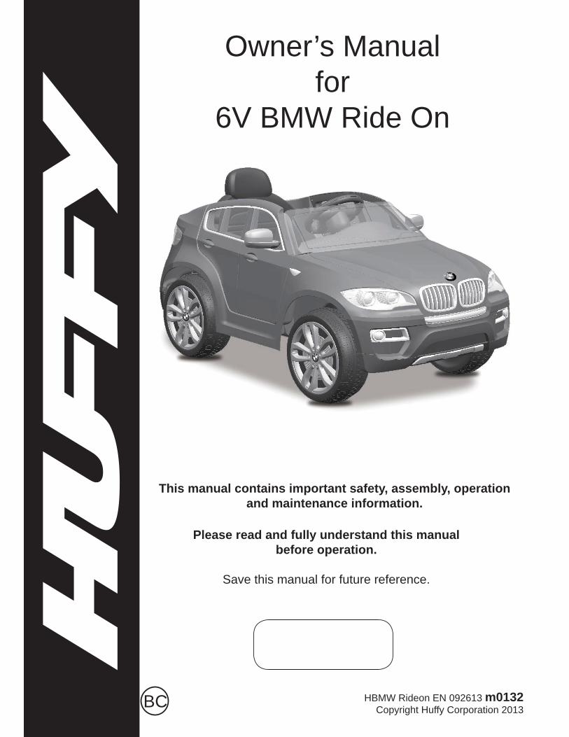
Owner’s Manual for
6V BMW Ride On
Please read and fully understand this manual before operation.
Save this manual for future reference.
This manual contains important safety, assembly, operation and maintenance information.
HBMW Rideon EN 092613 m0132Copyright Huffy Corporation 2013BC
2
Owner’s Manual Index
Safety• Warnings ...............................................................................................3-4• User Requirements ................................................................................ 5
Assembly• Parts Assembly View ............................................................................. 6• Parts Assembly List ............................................................................... 7• Drive Motor and Rear Wheel Installation ............................................... 8• Front Wheel Installation ......................................................................... 9• Steering Rod Installation ...................................................................... 10• Drive Battery Installation ....................................................................... 11• Motor Cover Installation ........................................................................ 12• Seat Installation .................................................................................... 13• Steering Wheel and Sound Effect Batteries ......................................... 14• Side Mirror Installation .......................................................................... 15
Operation• Operation and Features ........................................................................ 16
Maintenance and Service• General ................................................................................................. 17• Battery Re-charge Interval and Time .................................................... 17• Charging the Drive Battery ................................................................... 18• Battery Fuse ......................................................................................... 19• Battery Storage ..................................................................................... 19• Battery replacement and disposal ........................................................ 20
• Troubleshooting Guide .......................................................................21/22
Huffy Warranty• Huffy Corporation Limited Warranty ..................................................... 23
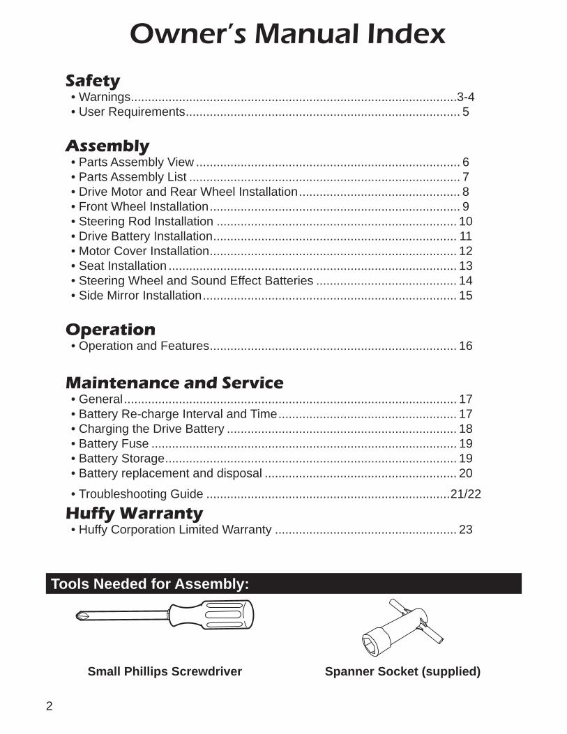
Tools Needed for Assembly:
Small Phillips Screwdriver Spanner Socket (supplied)
3
WARNINGThe user must follow all safety rules and guidelines below or serious injury or death may occur to the user.
• Always use common sense and safe practices when using the vehicle. This ve-hicle is unsuitable for children under 3 years. The user must be 3 to 5 years, and weigh no more than 65 lbs (30kgs).
• This product contains small parts that are for adult assembly only. Keep small children away when assembling. Remove and dispose of all protective material and poly bags before assembly. Be sure to remove all packaging materials and parts from underneath the vehicle body.
• Always use the vehicle in a safe, secure environment with continuous adult supervision.
• Body parts such as hands, legs, hair and clothing can get caught in moving parts. Never place a body part near a moving part or wear loose clothing while using the vehicle. Always wear shoes when using vehicle.
• Use on fl at, smooth paved surfaces only.• Using the vehicle on or near streets, motor vehicle, drop-offs such as: steps,
water (swimming pools), sloped surfaces, hills, wet areas, fl ammable vapors, in alleys, at night or in the dark could result in an accident.
• Do not use the vehicle in unsafe conditions such as snow, rain, loose dirt, mud sand or fi ne gravel. This may result in unexpected action such as tip over and skidding.
• This vehicle has no brakes. Motor friction will gradually stop the unit.• Do not use the vehicle in an unsafe manner. Examples include but are not limited
to:• Pulling the vehicle with another vehicle or similar device.• Allowing more than one rider.• Pushing the vehicle.• Traveling at an unsafe speed.
• There are additional hazards of using the vehicle in areas other than private grounds.
• Not to be used in traffi c.• The vehicle shall be used with caution since skill is required to avoid falls or colli-
sions.• Do not overload the vehicle.• Do not tow anything behind the vehicle.• Do not drive up steep slopes.• Do not drive into fi xed objects, which may cause the wheels to spin, causing the
motor to overheat.• Do not drive in very hot weather, components may overheat.• Do not allow water or other liquids to come in contact with the battery or other
electric components.• Do not tamper with the electrical system. Doing so may create a short, causing
the fuse to trip or other damage including fi re.• Child should always wear an approved helmet when using this product.
Safe
ty
4
Safe
ty WARNING - Charging the Drive Motor Battery
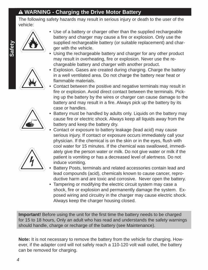
The following safety hazards may result in serious injury or death to the user of the vehicle:
• Use of a battery or charger other than the supplied rechargeable battery and charger may cause a fi re or explosion. Only use the supplied rechargeable battery (or suitable replacement) and char-ger with the vehicle.
• Using the rechargeable battery and charger for any other product may result in overheating, fi re or explosion. Never use the re-chargeable battery and charger with another product.
• Explosion. Gases are created during charging. Charge the battery in a well ventilated area. Do not charge the battery near heat or fl ammable materials.
• Contact between the positive and negative terminals may result in fi re or explosion. Avoid direct contact between the terminals. Pick-ing up the battery by the wires or charger can cause damage to the battery and may result in a fi re. Always pick up the battery by its case or handles.
• Battery must be handled by adults only. Liquids on the battery may cause fi re or electric shock. Always keep all liquids away from the battery and keep the battery dry.
• Contact or exposure to battery leakage (lead acid) may cause serious injury. If contact or exposure occurs immediately call your physician. If the chemical is on the skin or in the eyes, fl ush with cool water for 15 minutes. If the chemical was swallowed, immedi-ately give the person water or milk. Do not give water or milk if the patient is vomiting or has a decreased level of alertness. Do not induce vomiting.
• Battery Posts, terminals and related accessories contain lead and lead compounds (acid), chemicals known to cause cancer, repro-ductive harm and are toxic and corrosive. Never open the battery.
• Tampering or modifying the electric circuit system may case a shock, fi re or explosion and permanently damage the system. Ex-posed wiring and circuitry in the charger may cause electric shock. Always keep the charger housing closed.
Important! Before using the unit for the fi rst time the battery needs to be charged for 15 to 18 hours, Only an adult who has read and understands the safety warnings should handle, charge or recharge of the battery (see Maintenance).
Note: It is not necessary to remove the battery from the vehicle for charging. How-ever, if the adapter cord will not safely reach a 110-120 volt wall outlet, the battery can be removed for charging.
5
Safe
ty
User RequirementsThe suitable age range for a child using the vehicle is 3 to 5 years. The maximum weight of the child is 65 lbs (30 kg).Before using the vehicle the child must understand the controls and safety issues.They must also demonstrate the capability to handle the vehicle and operate its controls.It is the responsibility of the adult to educate the child, determine if they are fi t
to operate the vehicle, and supervise use.Here are basic safe riding rules you should read aloud to your child and anyone who may use the vehicle:
• An adult must always supervise a child that is using the vehicle.• Always sit in the seat when using the vehicle.• Keep your hands, hair and clothes away from moving parts. Always wear shoes
when using in the vehicle.• Do not use the vehicle on streets or near cars.• Children under three years old should not be allowed use the vehicle.• Only drive on level ground. Don’t go near water, drop-offs or up and down steep
slopes.• Don’t drive the vehicle in loose dirt, mud, sand or fi ne gravel. Using the vehicle
in loose dirt, mud, sand, or fi ne gravel may damage the electronics and gear box inside the vehicle.
Caution: Changes or modifi cations not expressly approved by the party responsible for compliance could void the user’s authority to operate the equipment.
NOTE: This equipment has been tested and found to comply with the limits for the Class B digital device, pursuant to Part 15 of the FCC Rules. These limits are de-signed to provide reasonable protection against harmful interference in a residential installation. This equipment generates uses and can radiate radio frequency energy and, if not installed and used in accordance with the instructions, may cause harmful interference to radio communications. However, there is no guarantee that interfer-ence will not occur in a particular installation. If this equipment does cause harmful interference to radio or television reception, which can be determined by turning the equipment off and on, the user is encouraged to try to correct the interference by one or more of the following measures:
• Reorient or relocate the receiving antenna.• Increase the separation between the equipment and receiver.• Connect the equipment into an outlet on a circuit different from that to which the
receiver is connected.• Consult the dealer or an experienced radio/TV technician for help.
Radio Frequency Information
6
Part
s Vi
ewParts View
1516
17
14
11
1815
1920
5
1
4
76
3
13
8
21
22
1210
9
15
18
12
11
15
16
2
15
1
16
LEFT
RIGHT
REAR AXLE STACK-UP
7
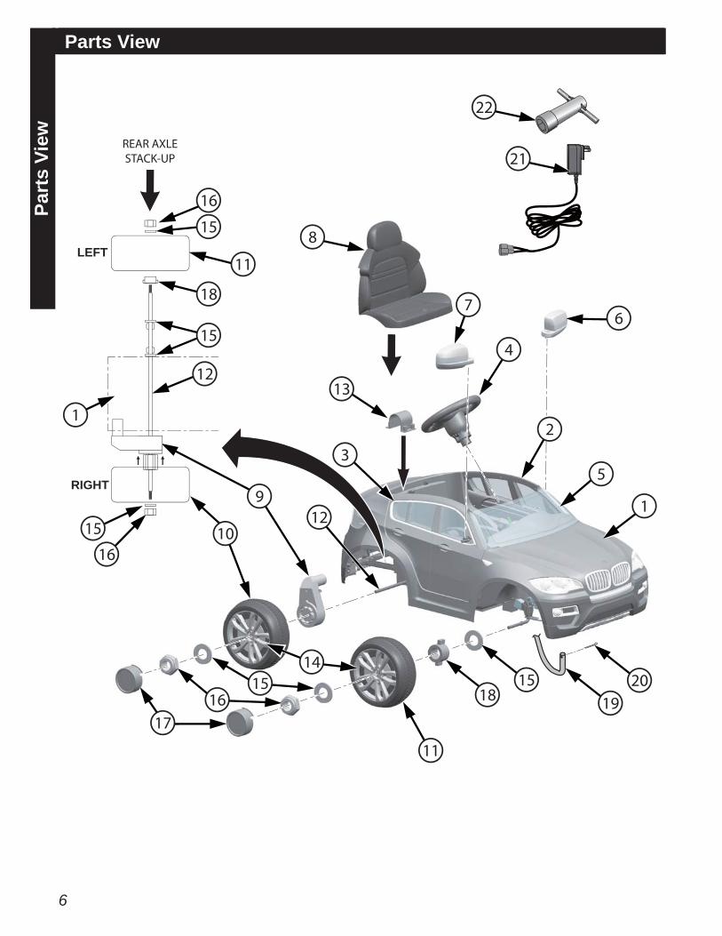
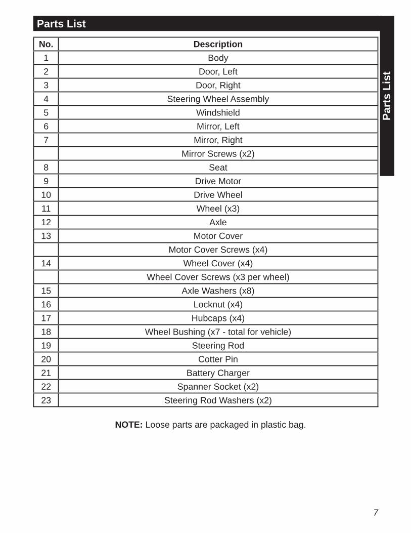
No. Description1 Body2 Door, Left3 Door, Right4 Steering Wheel Assembly5 Windshield6 Mirror, Left7 Mirror, Right
Mirror Screws (x2)8 Seat9 Drive Motor
10 Drive Wheel11 Wheel (x3)12 Axle13 Motor Cover
Motor Cover Screws (x4)14 Wheel Cover (x4)
Wheel Cover Screws (x3 per wheel)15 Axle Washers (x8)16 Locknut (x4)17 Hubcaps (x4)18 Wheel Bushing (x7 - total for vehicle)19 Steering Rod20 Cotter Pin21 Battery Charger22 Spanner Socket (x2)23 Steering Rod Washers (x2)
Part
s Li
st
Parts List
NOTE: Loose parts are packaged in plastic bag.
8
Installing the Drive Motor and Rear WheelsA
ssem
bly
Spanner
Rear axle
Spanner
Washer assembledalready
1716
1617
15
1118
10
15
9
15
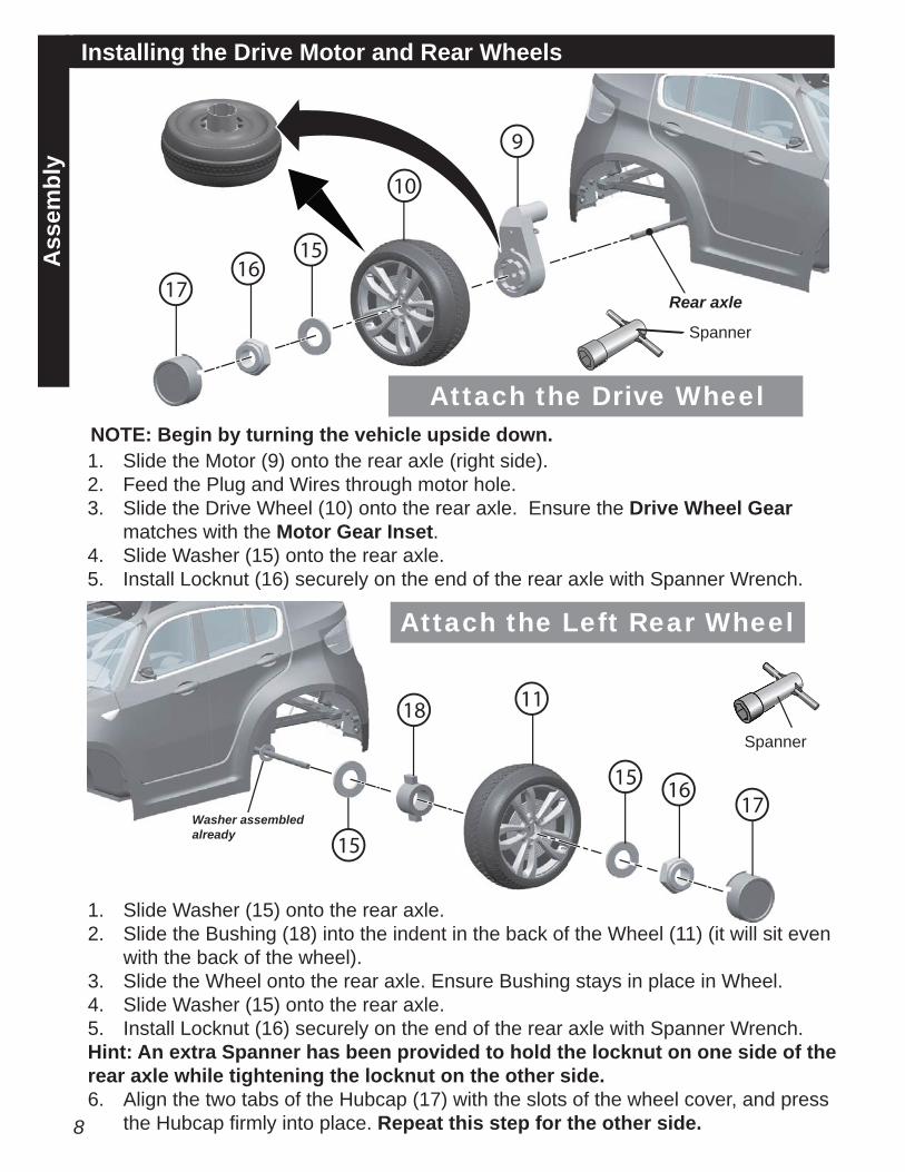
1. Slide the Motor (9) onto the rear axle (right side).2. Feed the Plug and Wires through motor hole.3. Slide the Drive Wheel (10) onto the rear axle. Ensure the Drive Wheel Gear
matches with the Motor Gear Inset.4. Slide Washer (15) onto the rear axle.5. Install Locknut (16) securely on the end of the rear axle with Spanner Wrench.
1. Slide Washer (15) onto the rear axle.2. Slide the Bushing (18) into the indent in the back of the Wheel (11) (it will sit even
with the back of the wheel).3. Slide the Wheel onto the rear axle. Ensure Bushing stays in place in Wheel.4. Slide Washer (15) onto the rear axle.5. Install Locknut (16) securely on the end of the rear axle with Spanner Wrench.Hint: An extra Spanner has been provided to hold the locknut on one side of the rear axle while tightening the locknut on the other side.6. Align the two tabs of the Hubcap (17) with the slots of the wheel cover, and press
the Hubcap fi rmly into place. Repeat this step for the other side.
Attach the Left Rear Wheel
Attach the Drive WheelNOTE: Begin by turning the vehicle upside down.
9
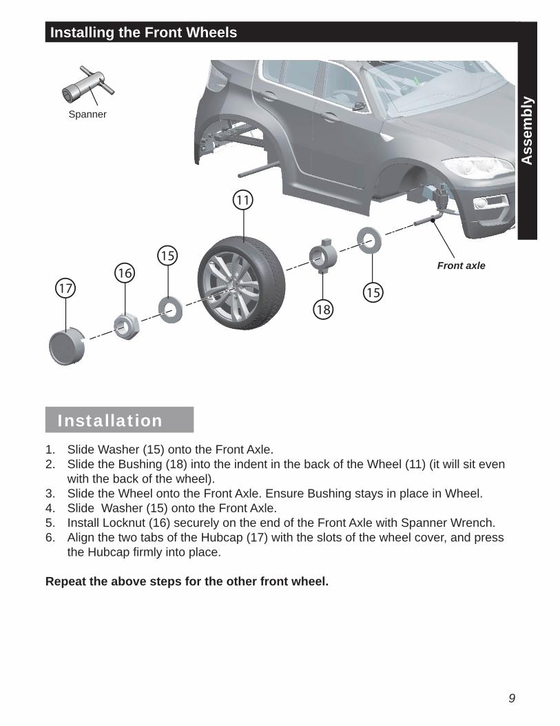
Installing the Front Wheels
Ass
embl
y
Spanner
Front axle16
17
15
11
1815
1. Slide Washer (15) onto the Front Axle.2. Slide the Bushing (18) into the indent in the back of the Wheel (11) (it will sit even
with the back of the wheel).3. Slide the Wheel onto the Front Axle. Ensure Bushing stays in place in Wheel.4. Slide Washer (15) onto the Front Axle.5. Install Locknut (16) securely on the end of the Front Axle with Spanner Wrench.6. Align the two tabs of the Hubcap (17) with the slots of the wheel cover, and press
the Hubcap fi rmly into place.
Repeat the above steps for the other front wheel.
Installation
10
Ass
embl
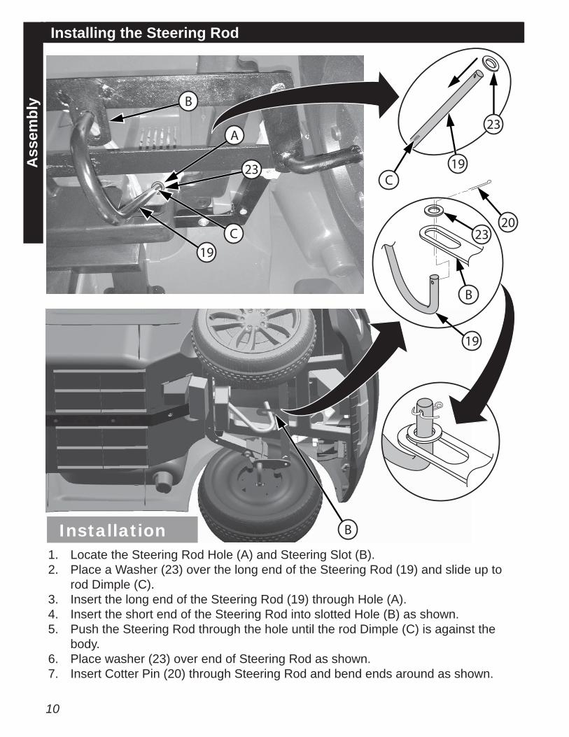
yInstalling the Steering Rod
B
B
19C
C19
B
A
23
23
23
19
20
1. Locate the Steering Rod Hole (A) and Steering Slot (B).2. Place a Washer (23) over the long end of the Steering Rod (19) and slide up to
rod Dimple (C).3. Insert the long end of the Steering Rod (19) through Hole (A).4. Insert the short end of the Steering Rod into slotted Hole (B) as shown.5. Push the Steering Rod through the hole until the rod Dimple (C) is against the
body.6. Place washer (23) over end of Steering Rod as shown.7. Insert Cotter Pin (20) through Steering Rod and bend ends around as shown.
Installation
11
Ass
embl
y
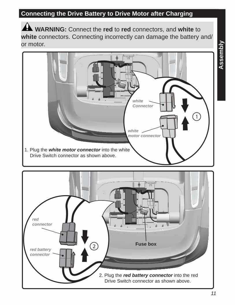
Connecting the Drive Battery to Drive Motor after Charging
Fuse box
whiteConnector
whitemotor connector
redconnector
red battery connector
1. Plug the white motor connector into the white Drive Switch connector as shown above.
2. Plug the red battery connector into the red Drive Switch connector as shown above.
2
1
WARNING: Connect the red to red connectors, and white to white connectors. Connecting incorrectly can damage the battery and/or motor.
12
Ass
embl
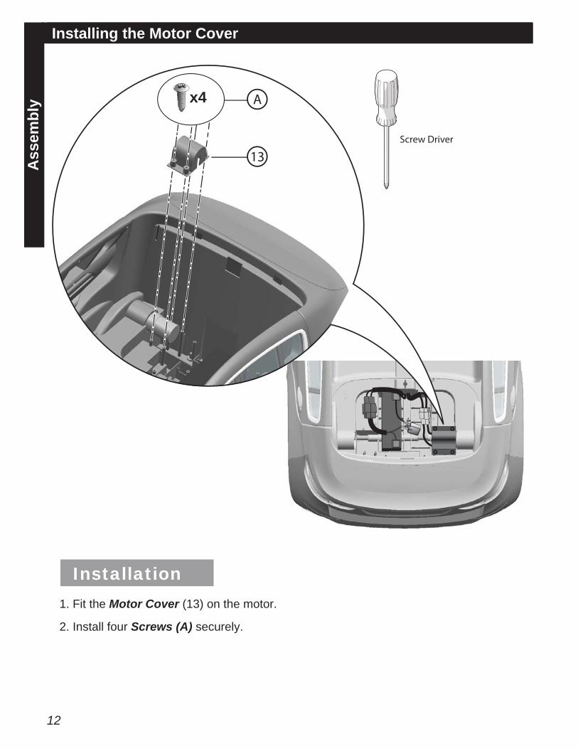
yInstalling the Motor Cover
1. Fit the Motor Cover (13) on the motor.
2. Install four Screws (A) securely.
Screw Driver
x4 A
13
Installation
13
Tabs
2
1 12
21
1
1
1
B
A
Lock
Ass
embl
y
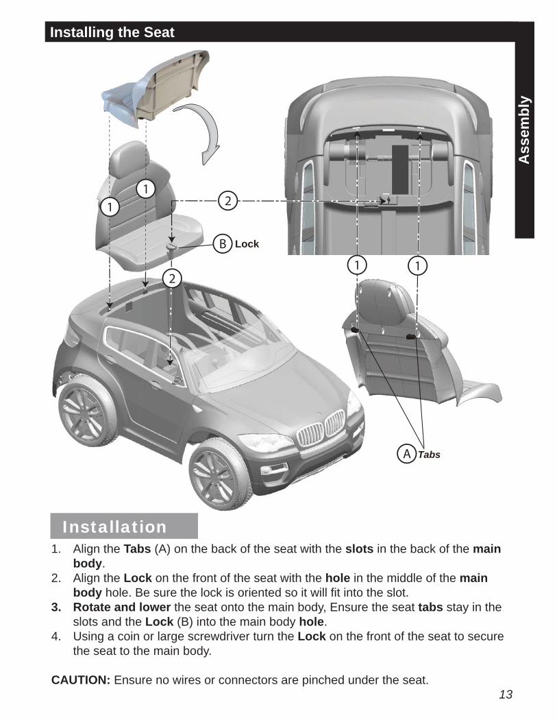
Installing the Seat
1. Align the Tabs (A) on the back of the seat with the slots in the back of the main body.
2. Align the Lock on the front of the seat with the hole in the middle of the main body hole. Be sure the lock is oriented so it will fi t into the slot.
3. Rotate and lower the seat onto the main body, Ensure the seat tabs stay in the slots and the Lock (B) into the main body hole.
4. Using a coin or large screwdriver turn the Lock on the front of the seat to secure the seat to the main body.
CAUTION: Ensure no wires or connectors are pinched under the seat.
Installation
14
Ass
embl
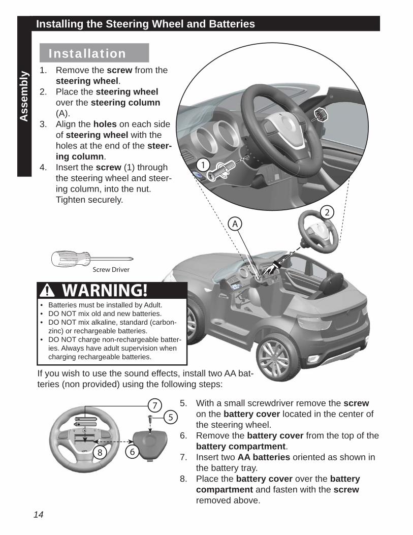
yInstalling the Steering Wheel and Batteries
4 3
13
1
8
7
6
A2
5
Screw Driver
1. Remove the screw from the steering wheel.
2. Place the steering wheel over the steering column (A).
3. Align the holes on each side of steering wheel with the holes at the end of the steer-ing column.
4. Insert the screw (1) through the steering wheel and steer-ing column, into the nut. Tighten securely.
If you wish to use the sound effects, install two AA bat-teries (non provided) using the following steps:
5. With a small screwdriver remove the screw on the battery cover located in the center of the steering wheel.
6. Remove the battery cover from the top of the battery compartment.
7. Insert two AA batteries oriented as shown in the battery tray.
8. Place the battery cover over the battery compartment and fasten with the screw removed above.
WARNING!• Batteries must be installed by Adult. • DO NOT mix old and new batteries.• DO NOT mix alkaline, standard (carbon-
zinc) or rechargeable batteries.• DO NOT charge non-rechargeable batter-
ies. Always have adult supervision when charging rechargeable batteries.
Installation
15
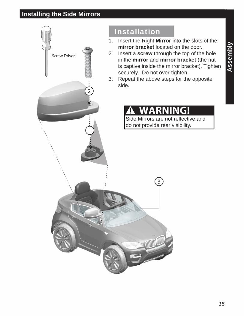
Installing the Side Mirrors
1
2
33
2
1
Screw Driver
1. Insert the Right Mirror into the slots of the mirror bracket located on the door.
2. Insert a screw through the top of the hole in the mirror and mirror bracket (the nut is captive inside the mirror bracket). Tighten securely. Do not over-tighten.
3. Repeat the above steps for the opposite side.
WARNING!Side Mirrors are not refl ective and do not provide rear visibility.
Installation
Ass
embl
y

16
Ope
ratio
nOperation and Features
Steering wheel2Sound buttons3
Shift lever4Power switch1
Foot pedal55
4
3
2
1
To Operate the vehicle:
1. Power Switch: Turns the vehicle on and off. Rock the switch to “ON” position to turn the vehicle on, - “OFF” position to turn it off. Leave OFF when not in use.
2. Steering wheel: Use to steer the vehicle in the direction you want to move.3. Sound Effects: Press the buttons on the sides of the steering wheel. Each button
will make a different sound.4. Shift Lever: Changes the direction the vehicle moves from forward to reverse.
• To move the car forward, shift the lever up.• To move the car backward, shift the lever down.• Shift the lever in the middle, the car will stop and not run.
CAUTION: To avoid damaging the motors and gears, DO NOT shift the lever when the car is moving.
5. Foot pedal: Applies power (speed) to the vehicle.• To move the car, press the pedal down.• To brake or slow down, release pressure from the pedal.
WARNING: Use on level ground ONLY. Motor friction will gradually stop the unit. Vehicle will roll down a steep incline, even when turned off.
17
Mai
nten
ance
The vehicle should be checked for damage, missing or badly worn parts before each use.
• Check the tightness of the fasteners before each use.• Check the tightness of the wheels:
• Note: If the drive wheel is not tight, it will not engage the gears and the vehicle will not run.
• Use a fl at head screwdriver to remove the hubcaps.• Ensure the axle is fully engaged in the lock nut.• Replace the hubcaps.
• Ensure the battery bracket is securely in place before use.• Store the vehicle indoors. Keep it away from sources of heat, such as stoves and
heaters.• Clean the vehicle with a soft, dry cloth. To restore shine to plastic parts, use a non-
wax furniture polish. Do not use automotive wax, abrasive cleaners or wash the vehicle with soap and water.
WARNING: Water will damage the motor, electrical system and battery.
Drive BatteryOnly an adult who has read and understands the safety warnings should handle, charge or recharge the battery. Failure to comply with all safety warnings may result in serious injury or death.
Maintenance
Re-charge Interval and TimeImportant!Check the drive battery and charger (supply cord, connector) for wear and damage before charging. Do not charge the battery if damage has occurred. Only replace with the same type 6V rechargeable battery and charger supplied by the manufacturer.
• Only use the rechargeable battery (or equivalent replacement) and charger sup-plied with your vehicle.
• Before fi rst use, charge battery 15 to 18 hours - never longer than 18 hours.• Once battery is depleted, recharge for 8 to 12 hours - never longer than 12 hours.• Do not short circuit the battery: Do NOT connect red and black wires together or
connect positive and negative terminals on the battery together.• When battery is fully charged, un-plug charger from the wall outlet and disconnect
from charger port.
The drive battery should be charged when depleted, or if not used regularly, once a month. Failure to charge the battery as directed will cause permanent damage to the battery and will void the warranty.
18
Mai
nten
ance
Charging the Drive Batteryg g y
Red connector
Red batteryConnector
ChargerConnector
Red batteryconnector
1
2
33
2
1
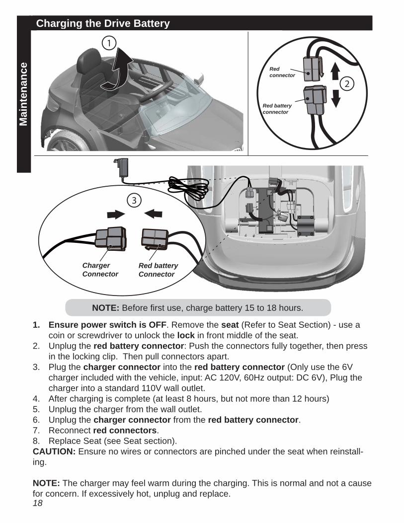
1. Ensure power switch is OFF. Remove the seat (Refer to Seat Section) - use a coin or screwdriver to unlock the lock in front middle of the seat.
2. Unplug the red battery connector: Push the connectors fully together, then press in the locking clip. Then pull connectors apart.
3. Plug the charger connector into the red battery connector (Only use the 6V charger included with the vehicle, input: AC 120V, 60Hz output: DC 6V), Plug the charger into a standard 110V wall outlet.
4. After charging is complete (at least 8 hours, but not more than 12 hours) 5. Unplug the charger from the wall outlet.6. Unplug the charger connector from the red battery connector.7. Reconnect red connectors.8. Replace Seat (see Seat section).CAUTION: Ensure no wires or connectors are pinched under the seat when reinstall-ing.
NOTE: The charger may feel warm during the charging. This is normal and not a cause for concern. If excessively hot, unplug and replace.
NOTE: Before fi rst use, charge battery 15 to 18 hours.
19
Mai
nten
ance
Battery storageDo not leave the battery connected in the vehicle for long period of times while not being used. This may drain the battery completely and cause permanent damage. Disconnect the battery connectors from the battery when the vehicle is not going to be used for a long period of time. Follow these guidelines if the battery is removed:
• Do not store battery in extreme hot or cold temperatures.• Do not place the battery on cement fl oors for extended periods. This will result in
battery discharge. Store the battery on a wood surface.• Wipe the battery clean with a dry cloth prior to storage. Wash cloth separate from
other clothes.
Battery FuseThe drive motor circuit features a thermal fuse that will automatically trip and cut all power to the vehicle if the motor, electric system or battery is overloaded. The fuse will reset and power will be restored after the unit is turned OFF for approximately fi ve minutes. If the thermal fuse trips repeatedly during normal use, the vehicle may need repair.
To avoid losing power, follow these guidelines:
• Do not overload the vehicle.• Do not tow anything behind the vehicle.• Do not drive up steep slopes.• Do not drive into fi xed objects, which may cause the wheels to spin, causing the
motor to overheat.• Do not drive in very hot weather, components may overheat.• Do not allow water or other liquids to come in contact with the battery or other
electric components.• Do not tamper with the electrical system. Doing so may create a short, causing
the fuse to trip.
20
Mai
nten
ance
Drive Battery Replacement and DisposalThe 6V battery will eventually lose the ability to hold a charge. Depending on the amount of use, and varying conditions, the battery should operate for one to three years. Follow these steps to replace and dispose the battery:
1. Remove the seat.2. Disconnect the battery connectors.3. Remove the metal battery bracket.4. Carefully lift the battery.
• Depending on the condition of the battery (i.e.: leakage) you may want to wear protective rubber gloves before removal.
• Do not lift the battery by its connectors or cables.5. Place the dead battery in a plastic bag.
Important! • The sealed lead-acid battery must be recycled or disposed of in an environmen-
tally sound manner.• Do not dispose of battery in a fi re. The battery may explode or leak acid.• Do not dispose of the battery in household trash. The incineration, land fi lling or
mixing of sealed lead-acid batteries with household trash is prohibited by law.• Return an exhausted battery to a federal or state approved lead-acid battery re-
cycler, such as a local seller of automotive batteries (check local battery disposal regulations).
NOTE: Replacement batteries are available at most battery supply stores. Document battery size and type (found on battery).
6. Install replacement battery and reconnect the connectors.7. Replace the metal battery bracket.8. Replace the seat.
21
Mai
nten
ance
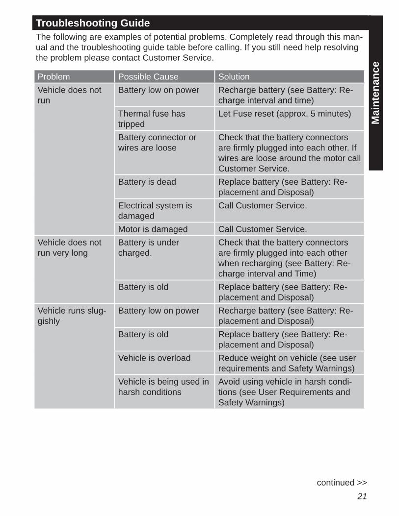
Troubleshooting GuideThe following are examples of potential problems. Completely read through this man-ual and the troubleshooting guide table before calling. If you still need help resolving the problem please contact Customer Service.
Problem Possible Cause SolutionVehicle does not run
Battery low on power Recharge battery (see Battery: Re-charge interval and time)
Thermal fuse has tripped
Let Fuse reset (approx. 5 minutes)
Battery connector or wires are loose
Check that the battery connectors are fi rmly plugged into each other. If wires are loose around the motor call Customer Service.
Battery is dead Replace battery (see Battery: Re-placement and Disposal)
Electrical system is damaged
Call Customer Service.
Motor is damaged Call Customer Service.Vehicle does not run very long
Battery is under charged.
Check that the battery connectors are fi rmly plugged into each other when recharging (see Battery: Re-charge interval and Time)
Battery is old Replace battery (see Battery: Re-placement and Disposal)
Vehicle runs slug-gishly
Battery low on power Recharge battery (see Battery: Re-placement and Disposal)
Battery is old Replace battery (see Battery: Re-placement and Disposal)
Vehicle is overload Reduce weight on vehicle (see user requirements and Safety Warnings)
Vehicle is being used in harsh conditions
Avoid using vehicle in harsh condi-tions (see User Requirements and Safety Warnings)
continued >>
22
Mai
nten
ance
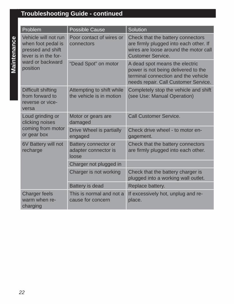
Troubleshooting Guide - continued
Problem Possible Cause SolutionVehicle will not run when foot pedal is pressed and shift lever is in the for-ward or backward position
Poor contact of wires or connectors
Check that the battery connectors are fi rmly plugged into each other. If wires are loose around the motor call Customer Service.
“Dead Spot” on motor A dead spot means the electric power is not being delivered to the terminal connection and the vehicle needs repair. Call Customer Service.
Diffi cult shifting from forward to reverse or vice-versa
Attempting to shift while the vehicle is in motion
Completely stop the vehicle and shift (see Use: Manual Operation)
Loud grinding or clicking noises coming from motor or gear box
Motor or gears are damaged
Call Customer Service.
Drive Wheel is partially engaged
Check drive wheel - to motor en-gagement.
6V Battery will not recharge
Battery connector or adapter connector is loose
Check that the battery connectors are fi rmly plugged into each other.
Charger not plugged inCharger is not working Check that the battery charger is
plugged into a working wall outlet.Battery is dead Replace battery.
Charger feels warm when re-charging
This is normal and not a cause for concern
If excessively hot, unplug and re-place.
23
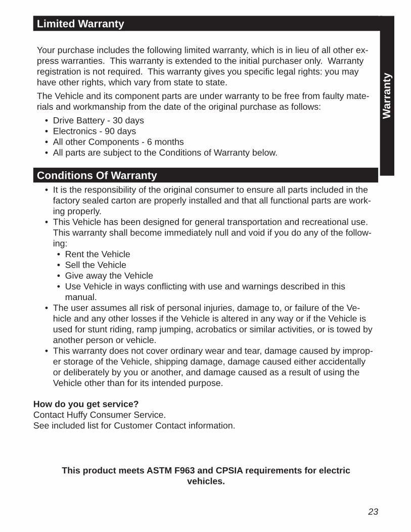
Limited Warranty
War
rant
y
Your purchase includes the following limited warranty, which is in lieu of all other ex-press warranties. This warranty is extended to the initial purchaser only. Warranty registration is not required. This warranty gives you specifi c legal rights: you may have other rights, which vary from state to state.The Vehicle and its component parts are under warranty to be free from faulty mate-rials and workmanship from the date of the original purchase as follows:
• Drive Battery - 30 days• Electronics - 90 days• All other Components - 6 months • All parts are subject to the Conditions of Warranty below.
Conditions Of Warranty• It is the responsibility of the original consumer to ensure all parts included in the
factory sealed carton are properly installed and that all functional parts are work-ing properly.
• This Vehicle has been designed for general transportation and recreational use. This warranty shall become immediately null and void if you do any of the follow-ing: • Rent the Vehicle• Sell the Vehicle• Give away the Vehicle• Use Vehicle in ways confl icting with use and warnings described in this
manual.• The user assumes all risk of personal injuries, damage to, or failure of the Ve-
hicle and any other losses if the Vehicle is altered in any way or if the Vehicle is used for stunt riding, ramp jumping, acrobatics or similar activities, or is towed by another person or vehicle.
• This warranty does not cover ordinary wear and tear, damage caused by improp-er storage of the Vehicle, shipping damage, damage caused either accidentally or deliberately by you or another, and damage caused as a result of using the Vehicle other than for its intended purpose.
How do you get service?Contact Huffy Consumer Service.See included list for Customer Contact information.
This product meets ASTM F963 and CPSIA requirements for electric vehicles.

H Helmet EN 100212 i0027
• Helmet should sit level on your head and low on your forehead• Adjust the strap sliders below the ear on both sides.• Buckle the chin strap. Adjust strap until it is snug.• No more than two fi ngers should fi t between the strap and your chin.• A proper fi tting helmet should be comfortable and not rock forward/back-
ward or side to side.• Always read the user manual that comes with your helmet to make sure it
is fi tted and attached properly to the wearer’s head according to the fi tting instructions described in the user manual.
CORRECT INCORRECT
Check www.Huffy.com for the current contact information
WARNING:ALWAYS WEAR YOUR
HELMET WHEN RIDING THIS PRODUCT!