blythe solar power project (09-afc-6) - · pdf fileimages are held approximately 18 inches...
TRANSCRIPT

BLYTHE SOLAR POWER PROJECT (09-AFC-6) CEC STAFF DATA REQUESTS 232 - 252
Technical Area: Visual Resources (AFC Section 5.15) Response Date: January 6, 2010
VIS-1
DR-VIS-232
Information Required:
Please establish a new KOP in the McCoy Mountains to the west of the Project site in the vicinity of coordinates - Latitude: 33° 39' 48.29" N, Longitude: 114° 48' 52.31" W, viewing to the east-northeast and provide a new KOP analysis and visual simulation (see Attachment DR-VIS 232 for perspective view guidance).
Response:
The KOP analysis and simulations are in progress and will be provided by January 13, 2010.
DR-VIS-233
Information Required:
Please establish a new KOP in the McCoy Mountains to the west of the Project site in the vicinity of coordinates - Latitude: 33° 39' 51.74" N, Longitude: 114° 49' 48.46" W, viewing to the east-northeast and provide a new KOP analysis and visual simulation (see Attachment DR-VIS-233 for perspective view guidance).
Response:
The KOP analysis and simulations are in progress and will be provided by January 13, 2010.
DR-VIS-234
Information Required:
In order to present simulations that more accurately capture the actual viewing experiences from the new McCoy Mountains KOPs, please present the existing view photographs and visual simulations as 11" x 17" images at a "life-size scale" when the images are held approximately 18 inches from the eye, so that the landscape and built features in the images match the actual scale of the features in the landscape (when the paper images are viewed at a distance of approximately 18 inches from the eye).
Response:
Visual simulations are in progress and will be provided by January 13, 2010.
DR-VIS-235
Information Required:
Please establish a new KOP on Black Creek Road, south of the Project site in the vicinity of coordinates - Latitude: 33° 38' 19.05" N, Longitude: 114° 45' 11.41" W, viewing to the
BLYTHE SOLAR POWER PROJECT (09-AFC-6) CEC STAFF DATA REQUESTS 232 - 252
Technical Area: Visual Resources (AFC Section 5.15) Response Date: January 6, 2010
VIS-2
north and provide a new KOP analysis and visual simulation (see DR-VIS-235 for perspective view guidance).
Response:
The KOP analysis and simulations are in progress and will be provided by January 13, 2010.
DR-VIS-236
Information Required:
In order to present a simulation that more accurately captures the actual viewing experience from the new Black Creek Road KOP, please present the existing view photograph and visual simulation as 11" x 17" images at a "life-size scale" when the images are held approximately 18 inches from the eye, so that the landscape and built features in the images match the actual scale of the features in the landscape (when the paper images are viewed at a distance of approximately 18 inches from the eye).
Response:
Visual simulations are in progress and will be provided by January 13, 2010.
DR-VIS-237
Information Required:
Please establish a new KOP on the four-wheel drive track, south of the Project site in the vicinity of coordinates - Latitude: 33° 38' 48.37" N, Longitude: 114° 46' 23.27" W, viewing to the north and provide a new KOP analysis and visual simulation (see DR-VIS-237 for perspective view guidance).
Response:
The KOP analysis and simulations are in progress and will be provided by January 13, 2010.
DR-VIS-238
Information Required:
In order to present a simulation that more accurately captures the actual viewing experience from the wind fence KOP, please present the existing view photograph and visual simulation as 11" x 17" images at a "life-size scale" when the image is held approximately 18 inches from the eye, so that the landscape and built features in the images match the actual scale of the features in the landscape (when the paper image is viewed at a distance of approximately 18 inches from the eye).

BLYTHE SOLAR POWER PROJECT (09-AFC-6) CEC STAFF DATA REQUESTS 232 - 252
Technical Area: Visual Resources (AFC Section 5.15) Response Date: January 6, 2010
VIS-3
Response:
Visual simulations are in progress and will be provided by January 13, 2010.
DR-VIS-239
Information Required:
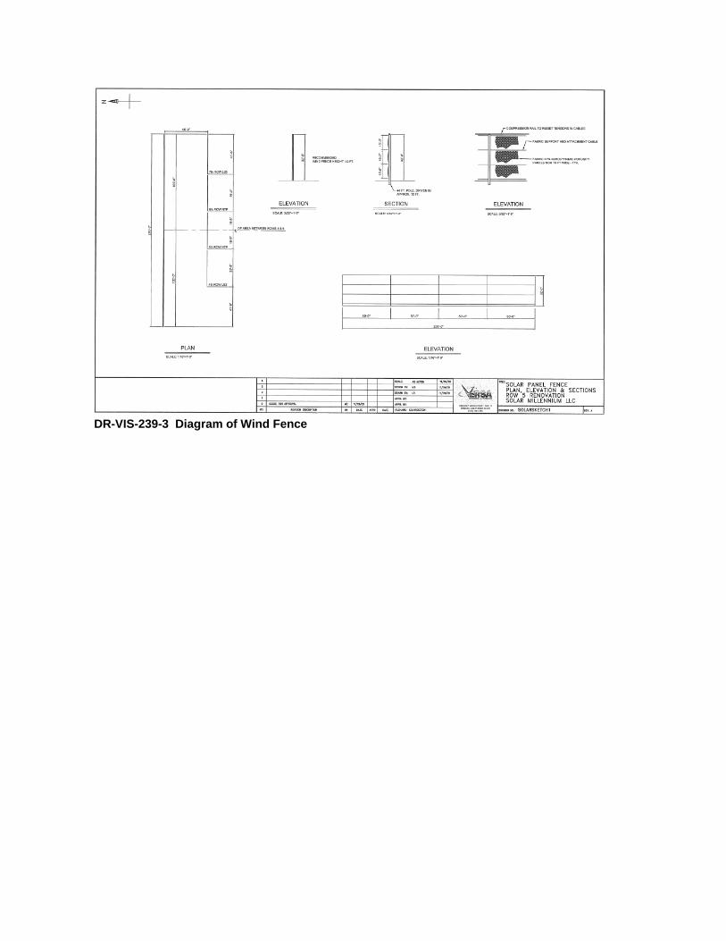
Please provide a detailed description and diagram of the wind fence including the fence color.
Response:
The wind fences will be installed to protect the solar arrays from high wind loads. The wind fences will be 30 feet tall and will be placed along the east and west boundaries of each solar field. The wind fences will be made of steel A-frames and a wire mesh, tan in color, much like that used to screen tennis courts. The wind load affects the wind fence in horizontal direction and the dead load only in vertical direction. The fence posts are spaced 4-meters apart, which is the span of the A-frames supporting the wire mesh. The wire mesh is fixed on horizontal steel ropes.
Figure DR-VIS-239-1 illustrates the framing of the wind fence prior to installation of the horizontal steel ropes and wire mesh. The photograph and diagram that follow (DR-VIS-239-2 and DR-VIS-239-3, respectively) further illustrate the look of the wind fence.
DR-VIS-240
Information Required:
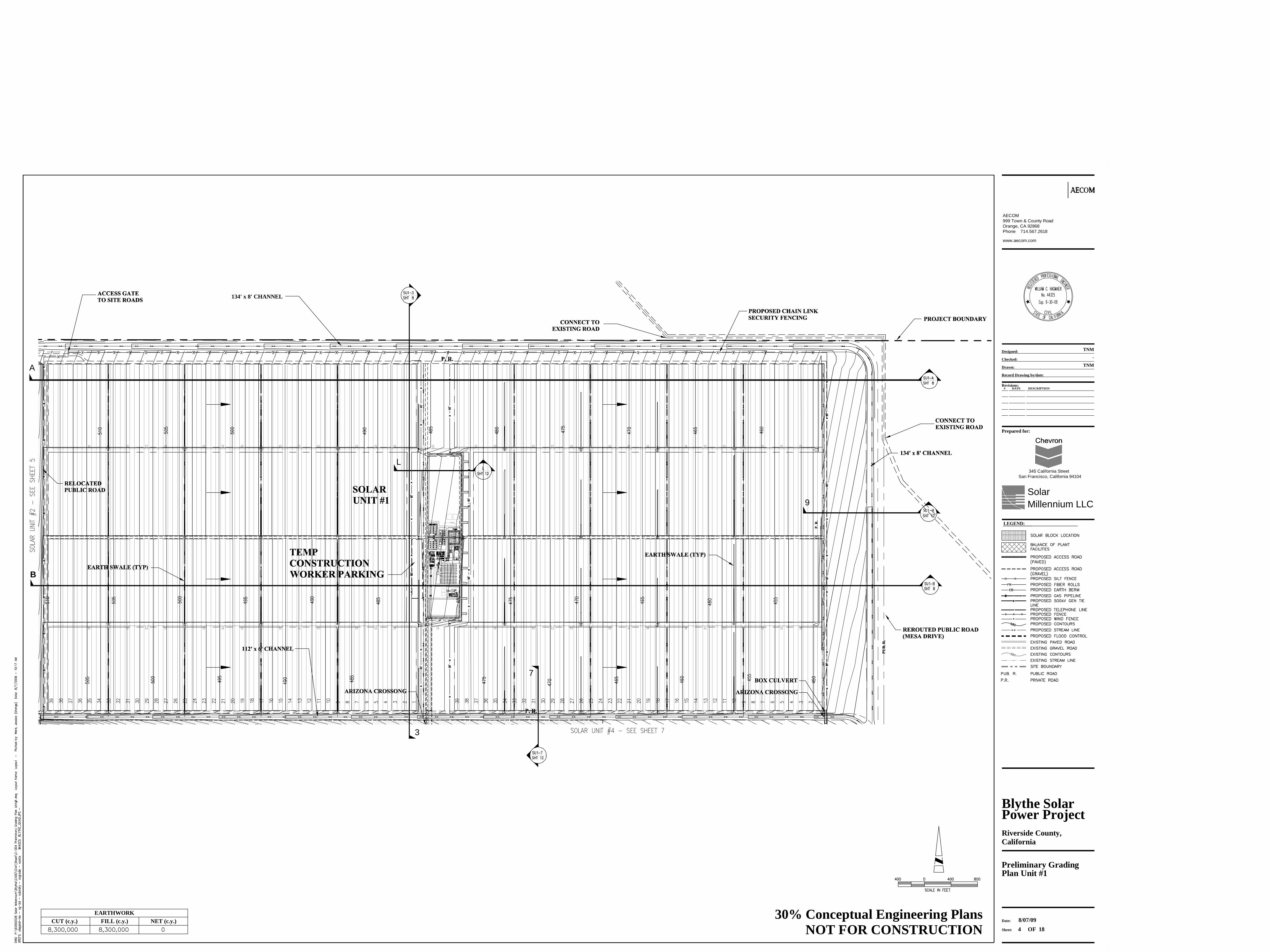
Please provide a site plan at a scale that clearly identifies the location of the various project components including the wind fences.
Response:
Please see Figure DR-VIS-240 for a site plan that identifies the location of the Project components for a representation of the location of the wind fences on the BSPP.
DR-VIS-241
Information Required:
Please identify which project components listed in Table 5.15-3 will have non-reflective surface treatments and neutral colors and please specify what those treatments and colors will be.

BLYTHE SOLAR POWER PROJECT (09-AFC-6) CEC STAFF DATA REQUESTS 232 - 252
Technical Area: Visual Resources (AFC Section 5.15) Response Date: January 6, 2010
VIS-4
Response:
Project components are painted either during the manufacturing process or in the field. Project components to be painted include:
Cooling towers (Bureau of Land Management [BLM] Standard Environmental Color: Covert Green 18-0617 TPX (RGB #7D745E) RGB: 125,116,94 – CMYK: 0,7,25,51);
Buildings and tanks within the power block (i.e., buildings and tanks – except piping and vessels) (BLM Standard Environmental Color: Covert Green 18-0617 TPX (RGB #7D745E) RGB: 125,116,94 – CMYK: 0,7,25,51);
Wind fences (black netting); and
Transmission monopoles (standard, non-specular grey).
Project components that cannot be painted include:
Electrical substation equipment (standard non-specular grey);
Transmission lattice structures (standard, nonspecular grey);
Piping and vessels within the power block (galvanized steel – grey);
Pedestals of parabolic troughs (galvanized steel - grey);
The backs of parabolic troughs (white); and
HTF insulation wrap (galvanized cladding - grey).
DR-VIS-242
Information Required:
Please provide a color pallet of the anticipated colors.
Response:
Cooling towers, buildings and tanks will be painted, as follows: BLM Standard Environmental Color: Covert Green 18-0617 TPX (RGB #7D745E) RGB: 125,116,94 – CMYK: 0,7,25,51
The backs of parabolic troughs will be white.
All other equipment will have standard manufacturer’s colors (specular and non-specular galvanized steel grey).
DR-VIS-243
Information Required:
In all new simulations requested above, please be sure to show facilities with the proposed surface treatments including appropriate color and texture.

BLYTHE SOLAR POWER PROJECT (09-AFC-6) CEC STAFF DATA REQUESTS 232 - 252
Technical Area: Visual Resources (AFC Section 5.15) Response Date: January 6, 2010
VIS-5
Response:
Facilities’ surface treatments will be shown in the simulations to be provided at completion of generation.
DR-VIS-244
Information Required:
Although the precise route of the transmission line is not yet known, please add the anticipated linear length of the transmission line, as presently shown, to Table 5.15-3.
Response:
The anticipated linear length of the transmission line as presently proposed is 32,365 feet from the Project central switchyard to the proposed Colorado River substation and this information has been added to Table 5.15-3 as requested.
Table Error! No text of specified style in document.-1 Equipment Dimensions
Legend / Name Dimensions (LxWxH)
(Feet)/Capacity Footprint
(square feet)
Switch Yard 13 x 92 1,200
Overflow Vessel And Expansion Vessel 124 x 154 19,000 Ea
Ullage Coolers And Vessel 79 x 20 1,000
Nitrogen System Incidental 800
Heat Transfer Fluid Heater 50 x 22 x 80 Stack 1,100
Steam Generators 90 x 10 x 24 Ea 900
Weather Station Building 68 x 68 x 24 (Two Level Bldg) 4,600
Parking 18 x 60 1,080
Balance Of Plant Electrical Building 67 x 67 x 24 (Two Level Bldg) 4,500
Reheaters 32 x 10 Ea 320
MCC Cooling Tower 33 x 40 x 32 High 1,320
Steam Turbine 111 x 50 x 40 High 5,500
Deaerator 125 x 57 7,100
Vacuum System 19 x 35 x 24 High 665
Compressed Air System 25 x 25 x 24 High 625
Generator Circuit Breaker 20 x 30 x 20 600
Warehouse 68 x 146 x 30 10,000
Chemical Injection Skid 46 x 47 x 24 2,000
BLYTHE SOLAR POWER PROJECT (09-AFC-6) CEC STAFF DATA REQUESTS 232 - 252
Technical Area: Visual Resources (AFC Section 5.15) Response Date: January 6, 2010
VIS-6
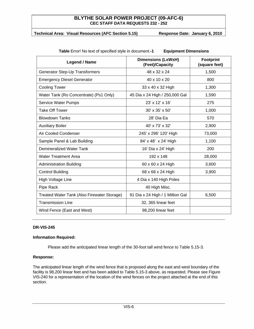
Table Error! No text of specified style in document.-1 Equipment Dimensions
Legend / Name Dimensions (LxWxH)
(Feet)/Capacity Footprint
(square feet)
Generator Step-Up Transformers 48 x 32 x 24 1,500
Emergency Diesel Generator 40 x 10 x 20 800
Cooling Tower 33 x 40 x 32 High 1,300
Water Tank (Ro Concentrate) (Ps1 Only) 45 Dia x 24 High / 250,000 Gal 1,590
Service Water Pumps 23' x 12' x 16' 275
Take Off Tower 30' x 35' x 50' 1,000
Blowdown Tanks 28' Dia Ea 570
Auxiliary Boiler 40' x 73' x 32' 2,900
Air Cooled Condenser 245' x 296' 120' High 73,000
Sample Panel & Lab Building 84' x 48' x 24' High 1,100
Demineralized Water Tank 16' Dia x 24' High 200
Water Treatment Area 192 x 148 28,000
Administration Building 60 x 60 x 24 High 3,600
Control Building 68 x 68 x 24 High 3,900
High Voltage Line 4 Dia x 140 High Poles
Pipe Rack 40 High Misc.
Treated Water Tank (Also Firewater Storage) 91 Dia x 24 High / 1 Million Gal 6,500
Transmission Line 32, 365 linear feet
Wind Fence (East and West) 98,200 linear feet
DR-VIS-245
Information Required:
Please add the anticipated linear length of the 30-foot tall wind fence to Table 5.15-3.
Response:
The anticipated linear length of the wind fence that is proposed along the east and west boundary of the facility is 98,200 linear feet and has been added to Table 5.15-3 above, as requested. Please see Figure VIS-240 for a representation of the location of the wind fences on the project attached at the end of this section.

BLYTHE SOLAR POWER PROJECT (09-AFC-6) CEC STAFF DATA REQUESTS 232 - 252
Technical Area: Visual Resources (AFC Section 5.15) Response Date: January 6, 2010
VIS-7
DR-VIS-246
Information Required:
Please identify the amount of time that lights are expected to be on at the plant site.
Response:
Security lighting in the BSPP power block and solar fields would operate during non-operating, non-sunlight hours. This ends up to be about 3,600 hours per year, with the following monthly profile.
January 373February 301March 310April 251May 253June 241July 255August 272September 281October 332November 343December 392
DR-VIS-247
Information Required:
Please provide close-up photographs of SCAs of the type proposed for the SM Palen Project. Please include photographs showing fronts, backs and mounting structures for the SCAs. If SCAs in the photographs differ in detail from those proposed under the SM Palen Project, please describe the differences.
Response:
Figures DR-VIS-247-1 and DR-VIS-247-2 are of the same type of SCAs to be installed on the California projects; therefore, there are no differences to describe.
DR-VIS-248
Information Required:
Please characterize the maximum potential brightness (luminance) of diffuse and spread reflection from mirrors in candela per square meter.

BLYTHE SOLAR POWER PROJECT (09-AFC-6) CEC STAFF DATA REQUESTS 232 - 252
Technical Area: Visual Resources (AFC Section 5.15) Response Date: January 6, 2010
VIS-8
Response:
The diffuse light and spread reflection coming off the parabolic mirrors from most visible angles during most hours of the day will simply reflect the global irradiation of the sky; clouds will also be visible in these reflections. This leads to a lower intensity of light with respect to the sun itself. The intensity of these reflections would be less than that of the instantaneous global diffuse radiation at the respective moment of measure. It can be foreseen that the diffuse reflections could vary from 200,000 candela per square meter in the morning and afternoon to as much as 700,000 depending on scattering due to cloud patterns. This would be in all cases less intense then staring it to the sky (not at the sun).
It is possible that the back reflected light or light not absorbed by both the envelope and steel annulus of Heat Collecting Element (HCE) can be seen in the reflection of the parabolic mirror at certain angles above the horizon, i.e. not viewable to someone on the ground. The intensity 11 feet or farther from the front of the vertex of the collector will be fully diverged direct (not diffuse) incidence luminance of the sun, but with a worst-case intensity approximately 20 percent less than the direct luminance of the sun; this would be similar to viewing a body of water from the sky.
DR-VIS-249
Information Required:
Please describe the hours in which the mirror surface of a trough could be visible to an off-site viewer on the ground, and the proportion of surface visible in the course of the day.
Response:
At the Blythe Power Plant, a 30-foot tall wind fence runs along the entire eastern and western perimeter of the plant. Consequently, anywhere along the eastern or western border, the wind fence will always block the view of the mirror surface for a person standing off site on the ground. However, a portion of the mirror surface is visible to an off-site viewer on the ground along the north or south perimeter. The distance from the collector to a person standing outside the perimeter fence is approximately 30 feet. The collector has an aperture of 22 feet and sits atop a 13-foot pylon. Depending on where a person is standing and the time of day, different quantities of mirror area are visible. During the start up until approximately 9:00 AM, the majority of the mirror surface is visible to viewers positioning themselves to see down the length of a row of collectors. As the collector continues to track the sun throughout the day, less and less of the mirror surface becomes visible. Between 11:00 AM to 1:00 PM, approximately only 20 percent (Note: The angle of the collector with respect to local time will change throughout the year, thus these are best estimations) of the mirror surface is visible. As the sun continues to the west, more of the mirror surface becomes visible.
DR-VIS-250
Information Required:
Please provide any available anecdotal information on glare effects of the Kramer Junction and existing SEGS projects, including photographs of off-site diffuse or spread glare, and images of the heated HCEs, as seen from public roads/viewpoints.

BLYTHE SOLAR POWER PROJECT (09-AFC-6) CEC STAFF DATA REQUESTS 232 - 252
Technical Area: Visual Resources (AFC Section 5.15) Response Date: January 6, 2010
VIS-9
Response:
Photo 1 shows glare that is a result of the spread reflection of the envelope of the HCE tube itself. In the Blythe project, a wind fence would be located on the east and west sides of the solar field effectively blocking this view of the collector. The view shown in Photo 2 is a viewing angle that would be possible at the Blythe project from public area, i.e. looking North or South down the rows of collectors through the security fence. Spread reflection can be seen from the HCE tubes and metal holders and other metal parts. The collector that is planned to be utilized in Blythe will be much taller with larger mirrors making it difficult to see most of the HCE during the time of the day shown here from this proximity. From a farther distance, more of the HCE would be visible, but as a viewer moves away from the collector, the intensity of any reflections would be diminished.
Photo 1: HCE Glare, view from area outside perimeter fence, looking east.
Photo 2: HCE Glare, view from area outside perimeter fence, looking northwest.

BLYTHE SOLAR POWER PROJECT (09-AFC-6) CEC STAFF DATA REQUESTS 232 - 252
Technical Area: Visual Resources (AFC Section 5.15) Response Date: January 6, 2010
VIS-10
DR-VIS-251
Information Required:
Please describe whether any portion of the HCEs would be visible to viewers on the ground, either on- or off-site. Please characterize the maximum potential brightness (luminance) of heated HCEs in candela per square meter.
Response:
As with the visibility of the mirror surface or front of the collector discussed in DR-VIS-249, the amount of the HCE tube that is visible to a viewer on the ground changes throughout the day as the collector tilts to follow the sun. The HCE tubes will be most visible during mornings and afternoon to a viewer looking down the length of a row of solar collectors, while during the hours approaching, at and directly after solar noon, only the ends of the tubes will be visible from the ground off or on site. The metal annulus of the HCE does not glow when heated, reflections off of and within the glass envelope surrounding it makes the HCE appear as such when tracking the sun. Most of the reflection off of the HCE is facing the mirror surface making it difficult for a viewer on the ground to see. It is possible for an on-site viewer to get close enough to the collector to experience the reflection at the end of the collector. At this proximity, one could theoretically be exposed to a maximum back reflectance of HCE envelope. This worst-case intensity could be 93 percent of the sun’s direct incidence radiation concentrated with respect to the HCE envelope (42 times) and not transmitted through the envelope (4 percent). During highest radiation levels around 1,200 watts per square meter, this leads to a back reflectance of 1,875 watts per square meter or 1.28 million candela per square meter. While this is deemed not eye damaging, maintenance workers and visitors to the site who plan to be in this proximity of the HCE will be required to where polarized sunglasses. Viewers standing outside the perimeter fence (at least 30 feet away) could only be exposed to a maximum of 1/10th of this luminance when uniform diffuse scatter is assumed at this distance.
DR-VIS-252
Information Required:
Please explain whether any portion of the directly reflected solar radiation could pass by the HCEs (the steel tube annulus) due to the total divergence factor of the reflectors. If so, how much? Is this amount sufficient to cause any potential retinal damage or flash blindness? Are there measures that would prevent such inadvertent off-site reflection (such as shielding of the HCEs, etc.)?
Response:
During morning and evening movement of the collector from the stow position to tracking position, it is possible that some amount of sunlight diverges from the collector focal point to a point farther in the distance. This could also occur in the event the drive pylon malfunctions, essentially freezing in place. Depending on the time of day and time of year and the distance from the face of the collector, the level of the divergence or the intensity of luminance can vary greatly. It has been calculated in previous

BLYTHE SOLAR POWER PROJECT (09-AFC-6) CEC STAFF DATA REQUESTS 232 - 252
Technical Area: Visual Resources (AFC Section 5.15) Response Date: January 6, 2010
VIS-11
submittals[1] that beam intensity reaches levels which pose a threat of retinal damage within distances of 100 feet of a collector facing east or west. At the Blythe project, a 30-foot wind fence will be erected along the east and west perimeter of the solar field. The wind fence effectively acts as large privacy fence blocking the view into the field.
1 San Joaquin Solar 1 & 2 – Application for Certification Volume 2, Appendix L, “Glint and Glare Study,” http://www.energy.ca.gov/sitingcases/sjsolar/documents/applicant/afc/AFC_volume_02/

Visual Resources Figures
Figure DR-VIS-239-1 Framing of the Wind Fence Prior to Installation of the Horizontal Steel Ropes
and Wire Mesh
Figure DR-VIS-239-2 DR-VIS-239-2 Close up of Wind Fence
Figure DR-VIS-239-3
DR-VIS-239-3 Diagram of Wind Fence
DR-VIS-240 Supporting Figures
Preliminary Site Plan (Location of Wind Fences) Preliminary Grading Plan Unit #1 Preliminary Grading Plan Unit #2 Preliminary Grading Plan Unit #3 Preliminary Grading Plan Unit #4
Typical Power Block
Figure DR-VIS-247-1
DR-VIS-247-1 Same SCA to be Installed (View from Front)
Figure DR-VIS-247-2 DR-VIS-247-2 Same SCA to be Installed (View from Below)

DR-VIS-239-1 Framing of the Wind Fence Prior to Installation of the Horizontal Steel Ropes and Wire Mesh
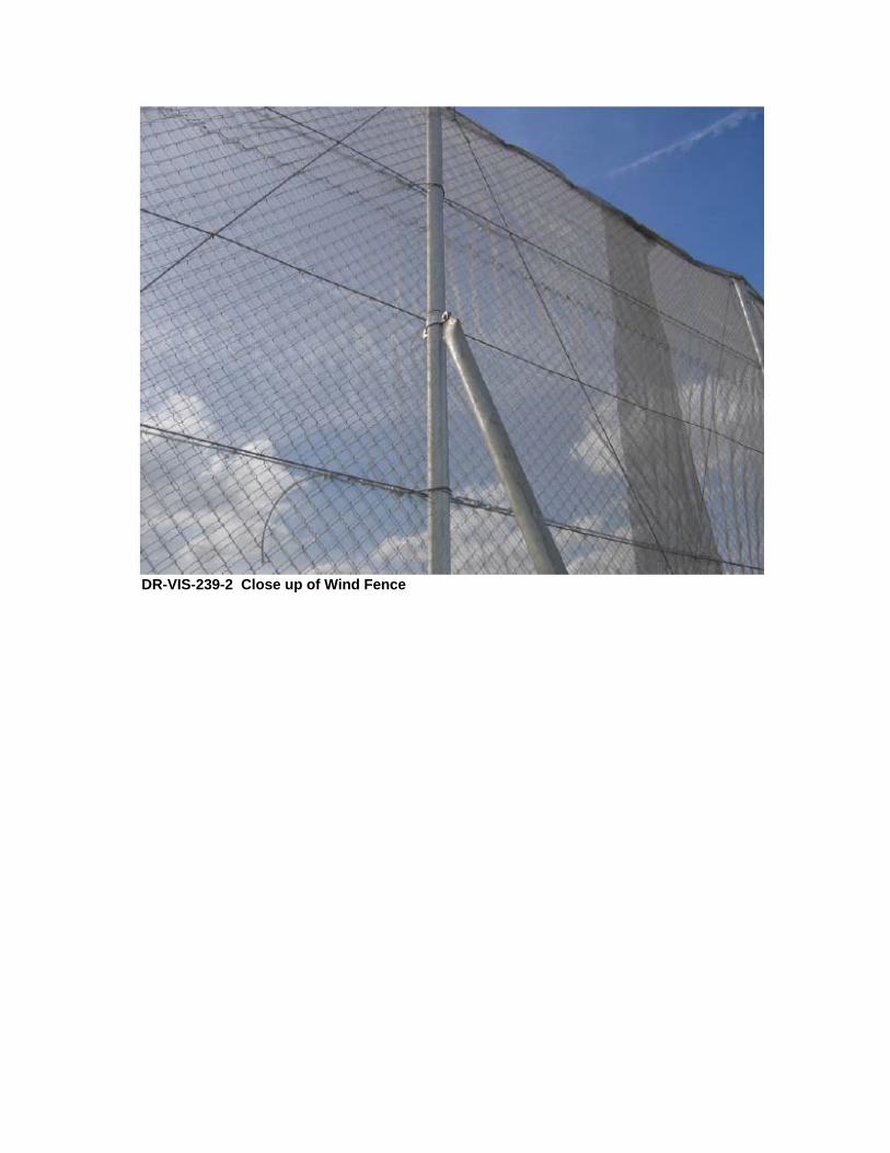
DR-VIS-239-2 Close up of Wind Fence
DR-VIS-239-3 Diagram of Wind Fence

DR-VIS-247-1 Same SCA to be Installed (View from Front)

DR-VIS-247-2 Same SCA to be Installed (View from Below)

DR-VIS-240
Supporting Figures
Preliminary Site Plan Preliminary Grading Plan Unit #1 Preliminary Grading Plan Unit #2 Preliminary Grading Plan Unit #3 Preliminary Grading Plan Unit #4
Typical Power Block

LEGEND:
134' x 8' CHANNEL
50
Blythe Solar
Riverside County,California
Preliminary GradingPlan Unit #1
4
TNM
-
TNM
Designed:
Checked:
Drawn:
Record Drawing by/date:
Revisions:# DATE DESCRIPTION
Prepared for:
Date:
Sheet:
AECOM
OF 188/07/09
999 Town & County RoadOrange, CA 92868Phone 714.567.2618
SolarMillennium LLC
www.aecom.com
345 California StreetSan Francisco, California 94104
30% Conceptual Engineering PlansNOT FOR CONSTRUCTION
Power Project
EARTHWORKCUT (c.y.) FILL (c.y.) NET (c.y.)
3
A
B
7
9
L

LEGEND:
134' x 8' CHANNEL
Blythe Solar
Riverside County,California
Preliminary GradingPlan Unit #2
5
TNM
-
TNM
Designed:
Checked:
Drawn:
Record Drawing by/date:
Revisions:# DATE DESCRIPTION
Prepared for:
Date:
Sheet:
AECOM
OF 188/07/09
999 Town & County RoadOrange, CA 92868Phone 714.567.2618
SolarMillennium LLC
www.aecom.com
345 California StreetSan Francisco, California 94104
30% Conceptual Engineering PlansNOT FOR CONSTRUCTION
Power Project
C
D
6
7
21
M
K
L

LEGEND:
178' x 8' CHANNEL
50
Blythe Solar
Riverside County,California
Preliminary GradingPlan Unit #3
6
TNM
-
TNM
Designed:
Checked:
Drawn:
Record Drawing by/date:
Revisions:# DATE DESCRIPTION
Prepared for:
Date:
Sheet:
AECOM
OF 188/07/09
999 Town & County RoadOrange, CA 92868Phone 714.567.2618
SolarMillennium LLC
www.aecom.com
345 California StreetSan Francisco, California 94104
30% Conceptual Engineering PlansNOT FOR CONSTRUCTION
Power Project
E
4
8
F
G
L
N

LEGEND:
50
Blythe Solar
Riverside County,California
Preliminary GradingPlan Unit #4
7
TNM
-
TNM
Designed:
Checked:
Drawn:
Record Drawing by/date:
Revisions:# DATE DESCRIPTION
Prepared for:
Date:
Sheet:
AECOM
OF 188/07/09
999 Town & County RoadOrange, CA 92868Phone 714.567.2618
SolarMillennium LLC
www.aecom.com
345 California StreetSan Francisco, California 94104
30% Conceptual Engineering PlansNOT FOR CONSTRUCTION
Power Project
5
H
I
J
L
O

# LEGEND / NAME DIMENSIONS (LxWxH) / CAPACITY FTPRINT (SF)
1 HTF MAIN PUMPS INCIDENTAL
2 HTF PUMPS SEAL OIL UNIT INCIDENTAL
3 SWITCH YARD 13' X 92' 1200SF
4 OVERFLOW VESSEL AND EXPANSION VESSEL 124' X 154' 19KSF EA
5 OVERFLOW RETURN PUMPS INCIDENTAL
6 ULLAGE COOLERS AND VESSEL 59' X 20' 1200SF
7 NITROGEN SYSTEM INCIDENTAL 800SF
8 HTF HEATER 50' X 22' X 80' STACK 1100SF
9 FREEZE PROTECTION PUMPS INCIDENTAL
10 STEAM GENERATORS 90' X 10' X 24' EA 900SF
11 VARIABLE FREQUENCY DRIVE SYSTEM INCIDENTAL
12 WEATHER STATION BUILDING 68' X 68' X 24' (TWO LEVEL BLDG) 4600SF
13 HTF PUMPS LUBE OIL UNIT INCIDENTAL
14 NOT USED
15 BALANCE OF PLANT ELECTRICAL BUILDING 67' X 67' X 24' (TWO LEVEL BLDG) 4500SF
16 REHEATERS 32' X 10' EA 320SF
17 EXCITATION TRANSFORMER NOT FOUND
18 WATER TREATMENT MCCS INCIDENTAL
19 MCC COOLING TOWER 33' X 40' X 32' HIGH 1320
20 STEAM TURBINE 111' X 50' X 40' HIGH 5500SF
21 GLAND CONDENSER INCIDENTAL
22 LUBE OIL CONSOLE INCIDENTAL
23 DEAERATOR 125' X 57' 7100SF
24 FEEDWATER PUMPS INCIDENTAL
25 CONDENSATE PUMPS INCIDENTAL
26 LP/HP PRE-HEATERS INCIDENTAL
27 VACUUM SYSTEM 19' X 35' X 24' HIGH 665
28 DIRTY WASTE WATER SUMP, OIL WATER SEPARATOR INCIDENTAL
29 FREE FOR USE
30 COMPRESSED AIR SYSTEM 25' X 25' X 24' HIGH 625 SF
31 GENERATOR CIRCUIT BREAKER 20' X 30' X 20' 600 SF
32 WAREHOUSE 68' X 146' X 30' 10K SF
33 CHEMICAL INJECTION SKID 46' X47' X 24' 2K SF
34 MAIN AUXILIARY TRANSFORMERS INCIDENTAL
35 GENERATOR STEP-UP TRANSFORMERS 48' X 32' X 24' 1,500 SF
36 EMERGENCY DIESEL GENERATOR 40' X 10' X 20' 400 SF
37 COOLING TOWER 33' X 40' X 32' HIGH 1,300 SF
38 FREE FOR USE
39 WATER TANK (RO CONCENTRATE) (BSP1 & 3 ONLY) 50' DIA X 24' HIGH / 300,000 GAL 1,600 SF
40 SERVICE WATER PUMPS 23' X 12' X 16' 275 SF
41 TAKE OFF TOWER 30' X 35' X 50' 1,000 SF
42 FIRE PROTECTION PUMPS INCIDENTAL
43 FREE FOR USE
44 BLOWDOWN TANKS 28' DIA EA 570 SF
45 TURBINE DRAINS TANK INCIDENTAL
46 CONDENSATE TANK INCIDENTAL
47 STG PACKAGED ELECTRONIC AND ELECTRICAL CONTROL COMPARTMENT INCIDENTAL
48 AUXILIARY BOILER 40' X 73' X 32' 2900 SF
49 AIR COOLED CONDENSER 245' X 296' 150' HIGH 73K SF
50 HTF PIPING CONNECTION TO SOLAR FIELD INCIDENTAL
51 SAMPLE PANEL & LAB BUILDING 84' X 48' X 24' HIGH 4,000 SF
52 DEMINERALIZED WATER TANK 16' DIA X 24' HIGH 200 SF
53 AUXILIARY COOLING WATER PUMPS INCIDENTAL
54 WATER TREATMENT AREA 192' X 148' 28K SF
55 ADMINISTRATION BUILDING 60' X 60' 24' HIGH 3,600 SF
56 CONTROL BUILDING 68' X 68' 24' HIGH 4,600 SF
57 HIGH VOLTAGE LINE 4' DIA 145' HIGH POLES
58 SUS TRANSFORMER & 480 V BUS INCIDENTAL
59 DEMINERALIZED WATER PUMPS INCIDENTAL
60 PIPE RACK 40' HIGH MISC.
61 TREATED WATER TANK (also FIREWATER STORAGE) 91' DIA X 24' HIGH / 1 MILLION GAL 6,500 SF
62 CHEMICAL FEED CANOPY NOT FOUND
63 NOT USED
64 NOT USED
65 NOT USED
66 NOT USED
70 NOT USED
71 NOT USED

DR-VIS-250
Letter regarding Parabolic Trough Mirror Design Letter regarding Parabolic Trough Mirror Array

850 Town Center Drive. 20th Floor
Costa Mesa, California 92628-1925
Tel: (714) 540-1235 Fax: (714) 755-8290
w . l w . c o m
FIRM IAFFILIATE OFFICES
Barcelona New Jersey
Brussels New Yoik
Chicago Northern Virginia
Frankfurt Orange County
Hamburg Paris
Hong Kong San Diego
October 9.2007 London San Francisco
Los Angeles Shanghai
Madrid Silicon Valley
Milan Singapore
Moscow Tokyo
Munich Washington. D.C.
File No. 039810-W01
VIA FEDEX DOCKET CALIFORNIA ENERGY COMMISSION Attn: Docket No. 07-AFC-1 1516 Ninth Street, MS-4 Sacramento, California 958 14-55 12
Re: Victorville 2 Hybrid Power Proiect: Docket No. 07-AFC-1
Dear Sirmadam:
Pursuant to California Code of Regulations, title 20, sections 1209, 1209.5, and 1210, enclosed herewith for filing please find a document entitled, "Parabolic Trough Mirror Design Prevents Escape of Reflected Incident Rays."
Please note that the enclosed submittal was filed today via electronic mail to your attention and to all parties on the CEC's current electronic proof of service list.
Paul E. Kihm Senior Paralegal
Enclosure
cc: CEC 07-AFC-1 Proof of Service List (wlencl. via e-mail) Michael J. Carroll, Esq. (wlencl.)

Parabolic Trough Mirror Design
Prevents Escape of Reflected Incident Rays
The design of W 2 ' s single axis solar collector essentially prevents the escape of incident rays that directly strike the surface of the mirror. This is accomplished by the fundamental physics of the parabolic reflector as shown at Figure A in EXHIBIT I (attached). All rays entering the parabolic reflector are concentrated at single point (the focal point), located % the distance of the arc's radius, shown as Fp in Figure A. A Parabolic Trough Mirror type solar array is engineered so as to place the Heat Collection Element (HCE) precisely at the Fp (see also Figure B, on the attached EXHIBIT I).
The solar array will track the East to West movement of the sun with an accuracy of 0.1 degrees. The concentrated area of the sun's reflected incident rays will be magnitudes smaller than the 70MM diameter of the HCE. The HCE positioned in this direct line of sight with the sun will block or absorb all entering direct incident or reflected incident rays. As a result, aircraft flying over the array will generally not be exposed to reflected incident rays of sunlight -- in other words, the sun itself (or any portions thereof) will not appear to pilots as a reflection in a mirror.
It is important to note that the HCE is encased in glass and will be a minor source of reflection as described below (this is generally what accounts for the "glittering" effect of parabolic trough solar arrays, often described as similar to flying over a body of water):
I) The HCE is designed to absorb and collect incident rays reflecting off the parabolic mirror but, of course, some incident rays will strike the HCE directly as it is located in front of the mirror. As a result, there will be some reflections from the glass coating the HCE; however, these reflections will be minor as the HCEs are designed to absorb sunlight, not reflect it.
2) The reflected incident rays of the sun will generally be directed to the lower portion of the HCE glass encasement by design and will produce a glow from the reflected scattered beams as they enter the collector. If an aircraft were positioned at exactly the right angle above the array, this "glow" phenomenon could be visible along the entire length of the collector element for an individual row of mirrors. However, there are no reflected incident rays of sunlight associated with this glow and the brilliancelintensity of the light is much less by comparison to reflected sunlight.
Based on practical experience and the Laws of physics, solar arrays using the parabolic trough mirror design do not produce significant glare or reflection that would pose a distraction to aviation. The fundamental reason for this conclusioncan be found in the design of the parabolic trough mirror. The focal point created by the parabolic mirror will not allow any concentrated rays to escape the solar field. As a result, descriptions by pilots over flying a solar thermal facility (SEGS) indicate that, with regard to reflective glare, the general appearance of the array from the air is similar to flying over a body of water (see for example, the attached e-mail from Peter Soderquist of SCLA describing a recent overflight of the existing SEGS plants).