blÜcher channel - esi.infocms.esi.info/media/documents/bluch_drainchannels_ml.pdf · founded in...
TRANSCRIPT

K E E P I N G U P T H E F L O W
S T A I N L E S S S T E E L D R A I N A G E S Y S T E M S
BLÜCHER® Channel

BLÜCHER® stainless steel drainage systems
Founded in Denmark in 1965, BLUCHER has developed into a leading manufacturer of stainless steel drainage systems including channels, drains, pipework, access covers and grease separators.
Today BLUCHER is an international company with around 300 employees and with subsiduaries and representatives worldwide.
For more information visit www.blucher.co.uk
CHANNEL

Channels for commercial and industrial applications
Contents
BLÜCHER channel .............................................2
Selecting a channel ........................................3
Channel range ....................................................4
Custom or standard channel ........................5
Channel range overview ................................5
Channel dimensions ........................................6
Channel grates ............................................... 13
Kitchen channel dimensions .................... 18
Kitchen channel grates ............................... 21
Lower parts and accessories ..................... 22
Channel options and extras ...................... 27
Technical details ............................................ 29
References ........................................................ 33
1
CHANNEL
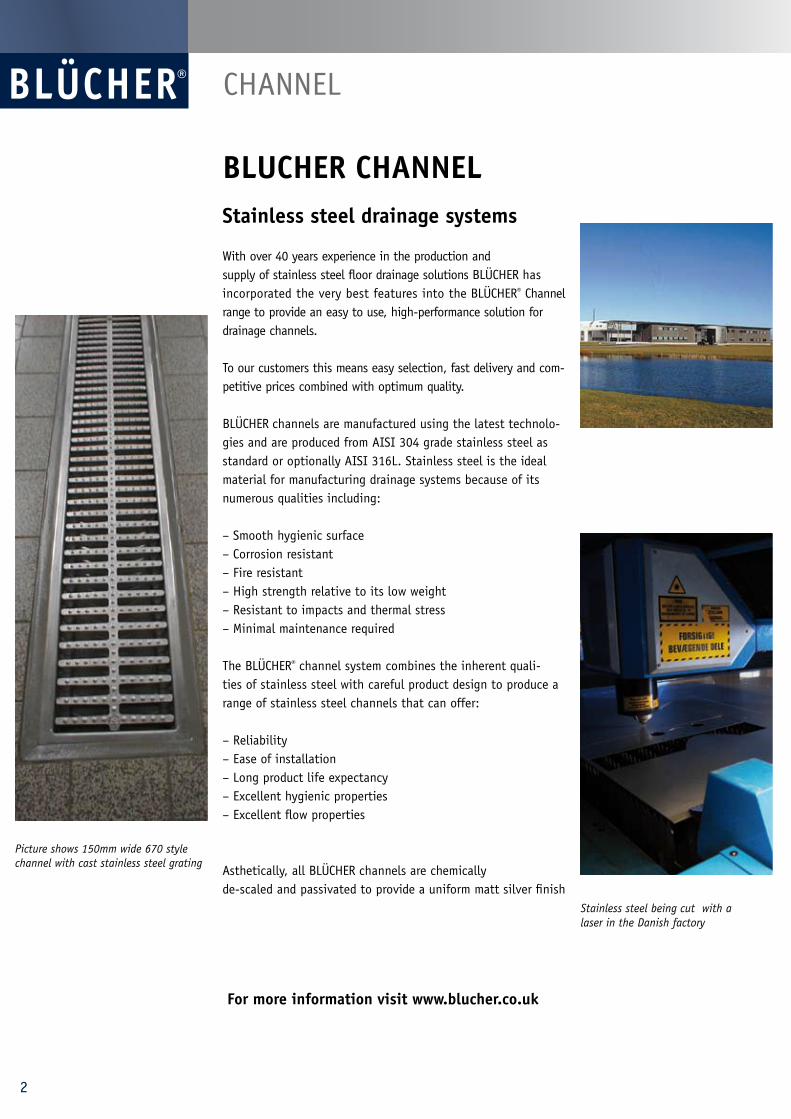
BLUCHER CHANNEL Stainless steel drainage systems
With over 40 years experience in the production and supply of stainless steel floor drainage solutions BLÜCHER has incorporated the very best features into the BLÜCHER® Channel range to provide an easy to use, high-performance solution for drainage channels.
To our customers this means easy selection, fast delivery and com-petitive prices combined with optimum quality.
BLÜCHER channels are manufactured using the latest technolo-gies and are produced from AISI 304 grade stainless steel as standard or optionally AISI 316L. Stainless steel is the ideal material for manufacturing drainage systems because of its numerous qualities including:
– Smooth hygienic surface – Corrosion resistant– Fire resistant– High strength relative to its low weight – Resistant to impacts and thermal stress– Minimal maintenance required
The BLÜCHER® channel system combines the inherent quali-ties of stainless steel with careful product design to produce a range of stainless steel channels that can offer:
– Reliability – Ease of installation – Long product life expectancy – Excellent hygienic properties – Excellent flow properties
Asthetically, all BLÜCHER channels are chemically de-scaled and passivated to provide a uniform matt silver finish
For more information visit www.blucher.co.uk
Picture shows 150mm wide 670 style channel with cast stainless steel grating
Stainless steel being cut with a laser in the Danish factory
2
Selecting a channel system:• Water load - continuous water flow - intermittent discharge - washdown
It is important to ensure that the lower part and trap arrangement has adequate flow capacity for the application.
• Waste products When chosing a grating consideration should be taken to ensu-
re that any solids in waste water can pass through the chosen grate.
• Loading This can influence the choice of channel width as well as deter mining the most appropriate grating for the application.
• Stainless steel grade AISI 304 (EN 1.4301) AISI 316L (EN1.4404)
• Floor covering Concrete/tiles/in-situ (e.g. epoxy resin) or flexible sheet (e.g.
vinyl).
• Membrane type Where required liquid or dry membrane application will determine the choice of lower part.
See also technical information on page 29.
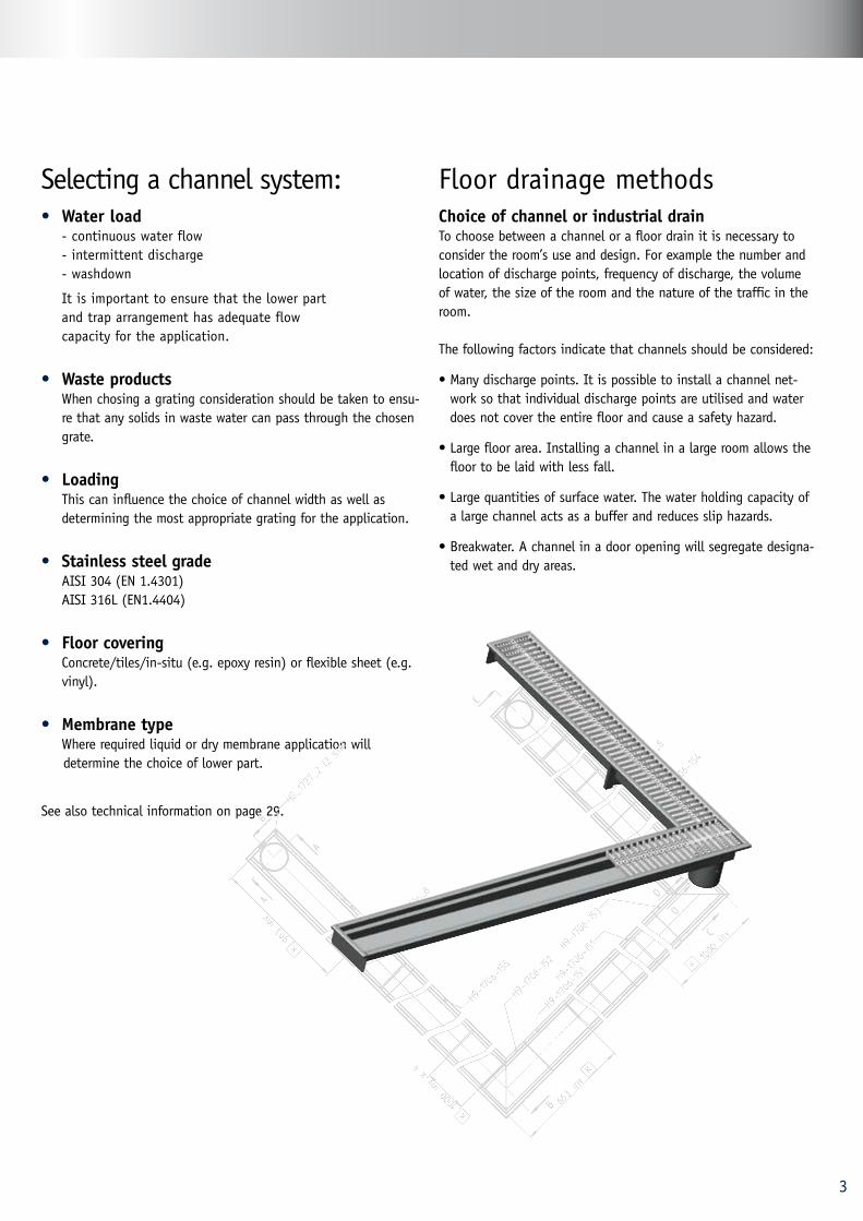
Floor drainage methodsChoice of channel or industrial drainTo choose between a channel or a floor drain it is necessary to consider the room’s use and design. For example the number and location of discharge points, frequency of discharge, the volume of water, the size of the room and the nature of the traffic in the room.
The following factors indicate that channels should be considered:
• Many discharge points. It is possible to install a channel net-work so that individual discharge points are utilised and water does not cover the entire floor and cause a safety hazard.
• Large floor area. Installing a channel in a large room allows the floor to be laid with less fall.
• Large quantities of surface water. The water holding capacity of a large channel acts as a buffer and reduces slip hazards.
• Breakwater. A channel in a door opening will segregate designa-ted wet and dry areas.
3
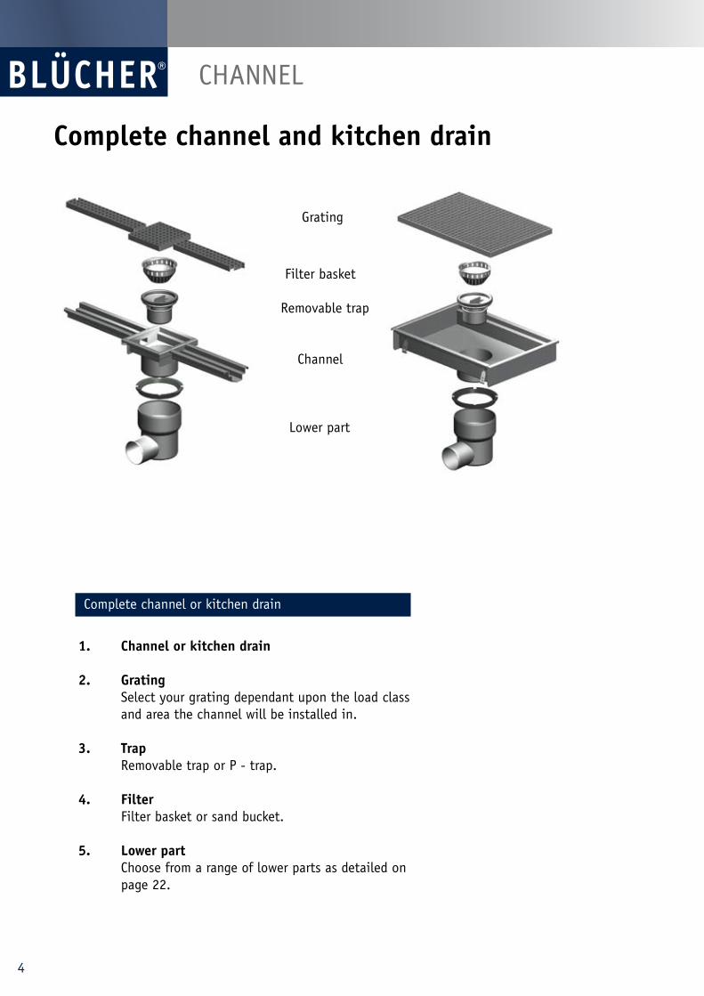
Complete channel and kitchen drain
Complete channel or kitchen drain
1. Channel or kitchen drain
2. Grating Select your grating dependant upon the load class and area the channel will be installed in.
3. Trap Removable trap or P - trap.
4. Filter Filter basket or sand bucket.
5. Lower part Choose from a range of lower parts as detailed on page 22.
Grating
Filter basket
Removable trap
Channel
Lower part
CHANNEL
4
Channel range overview
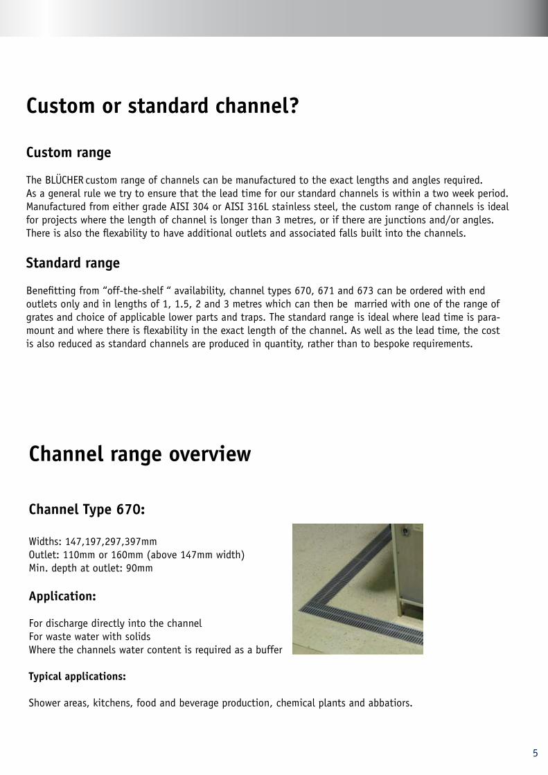
Channel Type 670:
Widths: 147,197,297,397mm Outlet: 110mm or 160mm (above 147mm width)Min. depth at outlet: 90mm
Application:
For discharge directly into the channel For waste water with solids Where the channels water content is required as a buffer
Typical applications:
Shower areas, kitchens, food and beverage production, chemical plants and abbatiors.
Custom or standard channel?
Custom range
The BLÜCHER custom range of channels can be manufactured to the exact lengths and angles required. As a general rule we try to ensure that the lead time for our standard channels is within a two week period. Manufactured from either grade AISI 304 or AISI 316L stainless steel, the custom range of channels is ideal for projects where the length of channel is longer than 3 metres, or if there are junctions and/or angles. There is also the flexability to have additional outlets and associated falls built into the channels.
Standard range
Benefitting from “off-the-shelf “ availability, channel types 670, 671 and 673 can be ordered with end outlets only and in lengths of 1, 1.5, 2 and 3 metres which can then be married with one of the range of grates and choice of applicable lower parts and traps. The standard range is ideal where lead time is para-mount and where there is flexability in the exact length of the channel. As well as the lead time, the cost is also reduced as standard channels are produced in quantity, rather than to bespoke requirements.
5
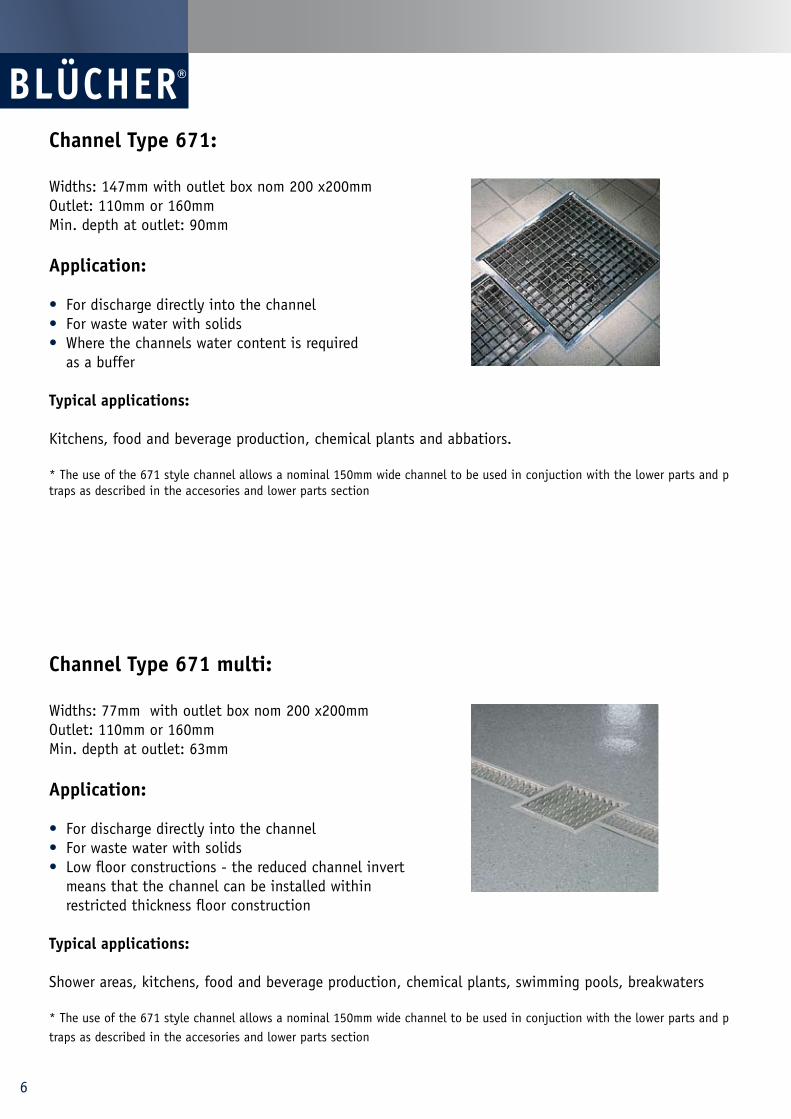
Channel Type 671 multi:
Widths: 77mm with outlet box nom 200 x200mmOutlet: 110mm or 160mm Min. depth at outlet: 63mm
Application:
• For discharge directly into the channel • For waste water with solids • Low floor constructions - the reduced channel invert means that the channel can be installed within restricted thickness floor construction
Typical applications:
Shower areas, kitchens, food and beverage production, chemical plants, swimming pools, breakwaters
* The use of the 671 style channel allows a nominal 150mm wide channel to be used in conjuction with the lower parts and p traps as described in the accesories and lower parts section
Channel Type 671:
Widths: 147mm with outlet box nom 200 x200mmOutlet: 110mm or 160mm Min. depth at outlet: 90mm
Application:
• For discharge directly into the channel • For waste water with solids • Where the channels water content is required as a buffer
Typical applications:
Kitchens, food and beverage production, chemical plants and abbatiors.
* The use of the 671 style channel allows a nominal 150mm wide channel to be used in conjuction with the lower parts and p traps as described in the accesories and lower parts section
6
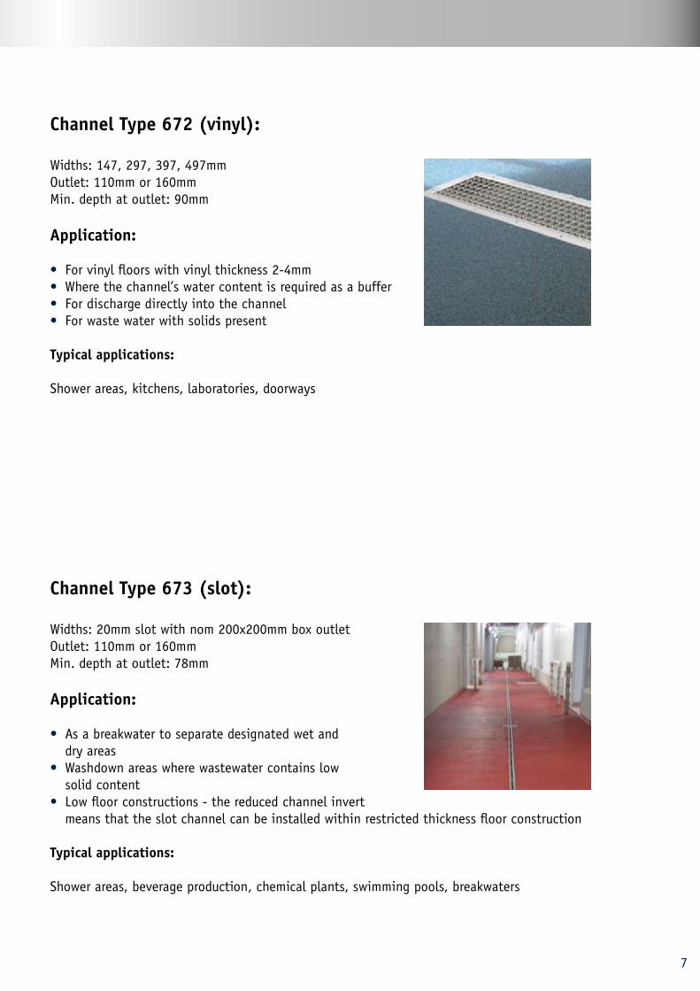
Channel Type 672 (vinyl):
Widths: 147, 297, 397, 497mmOutlet: 110mm or 160mm Min. depth at outlet: 90mm
Application:
• For vinyl floors with vinyl thickness 2-4mm• Where the channel’s water content is required as a buffer • For discharge directly into the channel • For waste water with solids present
Typical applications:
Shower areas, kitchens, laboratories, doorways
Channel Type 673 (slot):
Widths: 20mm slot with nom 200x200mm box outlet Outlet: 110mm or 160mm Min. depth at outlet: 78mm
Application:
• As a breakwater to separate designated wet and dry areas• Washdown areas where wastewater contains low solid content• Low floor constructions - the reduced channel invert means that the slot channel can be installed within restricted thickness floor construction
Typical applications:
Shower areas, beverage production, chemical plants, swimming pools, breakwaters
7
8
Channel dimensions
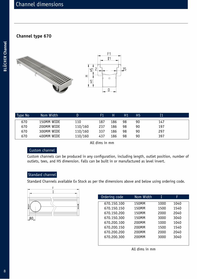
Type No Nom Width D F1 H H1 H5 I1
670 150MM WIDE 110 187 186 98 90 147 670 200MM WIDE 110/160 237 186 98 90 197 670 300MM WIDE 110/160 337 186 98 90 297 670 400MM WIDE 110/160 437 186 98 90 397
Channel type 670
Ordering code Nom Width I F
670.150.100 150MM 1000 1040 670.150.150 150MM 1500 1540 670.150.200 150MM 2000 2040 670.150.300 150MM 3000 3040 670.200.100 200MM 1000 1040 670.200.150 200MM 1500 1540 670.200.200 200MM 2000 2040 670.200.300 200MM 3000 3040
80
Custom channels can be produced in any configuration, including length, outlet position, number of outlets, tees, and H5 dimension. Falls can be built in or manufactured as level invert.
Standard Channels available Ex Stock as per the dimensions above and below using ordering code.
Custom channel
I
I
All dims in mm
All dims in mm
Standard channel
9
Channel dimensions
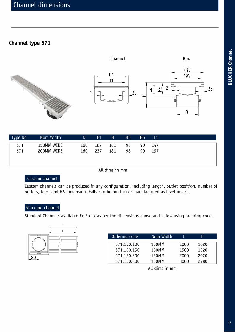
Type No Nom Width D F1 H H5 H6 I1
671 150MM WIDE 160 187 181 98 90 147 671 200MM WIDE 160 237 181 98 90 197
Channel type 671
Ordering code Nom Width I F
671.150.100 150MM 1000 1020 671.150.150 150MM 1500 1520 671.150.200 150MM 2000 2020 671.150.300 150MM 3000 2980
80
Custom channels can be produced in any configuration, including length, outlet position, number of outlets, tees, and H6 dimension. Falls can be built in or manufactured as level invert.
Standard channel
Standard Channels available Ex Stock as per the dimensions above and below using ordering code.
I
I
Channel Box
All dims in mm
All dims in mm
Custom channel
Standard channel
10
Channel dimensions
Type No Nom Width D F1 H H5 H6 I1
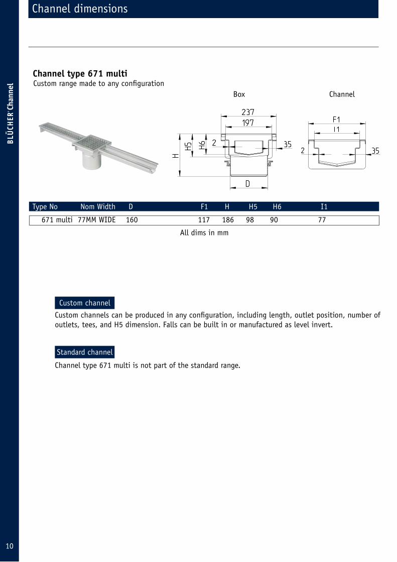
671 multi 77MM WIDE 160 117 186 98 90 77
Channel type 671 multi
Custom channels can be produced in any configuration, including length, outlet position, number of outlets, tees, and H5 dimension. Falls can be built in or manufactured as level invert.
Channel type 671 multi is not part of the standard range.
Custom range made to any configuration
All dims in mm
Box Channel
Custom channel
Standard channel
11
Channel dimensions
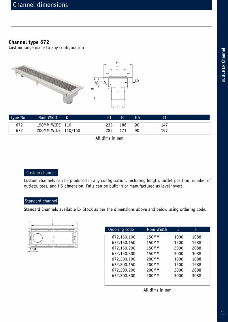
Type No Nom Width D F1 H H5 I1
672 150MM WIDE 110 235 186 90 147 672 200MM WIDE 110/160 285 171 90 197
Channel type 672
Ordering code Nom Width I F
672.150.100 150MM 1000 1088 672.150.150 150MM 1500 1588 672.150.200 150MM 2000 2088 672.150.300 150MM 3000 3088 672.200.100 200MM 1000 1088 672.200.150 200MM 1500 1588 672.200.200 200MM 2000 2088 672.200.300 200MM 3000 3088
Custom channels can be produced in any configuration, including length, outlet position, number of outlets, tees, and H5 dimension. Falls can be built in or manufactured as level invert.
Standard Channels available Ex Stock as per the dimensions above and below using ordering code.
I
I
115
Custom range made to any configuration
All dims in mm
All dims in mm
Custom channel
Standard channel

12
Channel dimensions
Type No Nom Width D H H5 H6
673 150MM WIDE 160 166 85 78
Channel type 673
Ordering code F Grate codes
673.000.300 3217 Mesh .22 673.000.400 4237 Ladder .25 673.000.500 5237 Cast .60 673.000.600 6197 673.000.700 7241
Custom channels can be produced in any configuration, including length, outlet position, number of outlets, tees, and H5 dimension. Falls can be built in or manufactured as level invert.
Standard Channels available Ex Stock as per the dimensions above and below using ordering code.
All dims in mm
All dims in mm
Box Channel
To add a grate to your order simply suffix the appropriate grate code to the channel ordering code.For example 673.000.030.22
Custom range made to any configuration
Custom channel
Standard channel
13
Channel grates
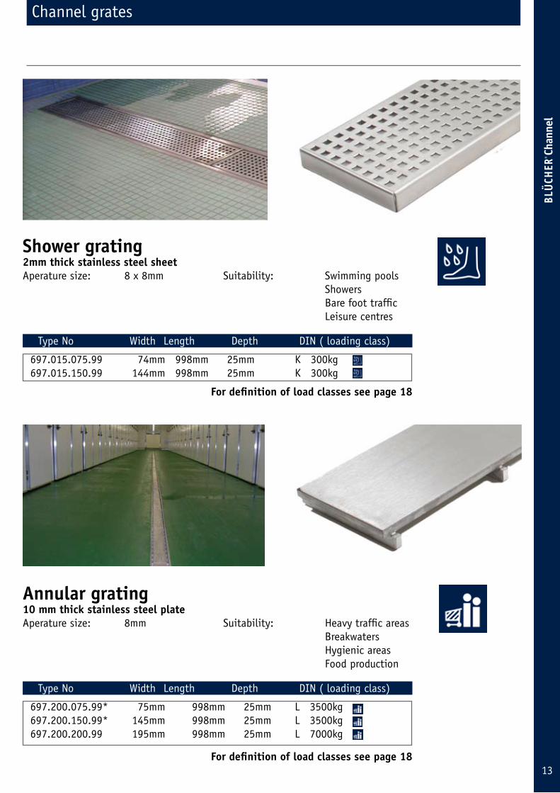
Shower grating2mm thick stainless steel sheetAperature size: 8 x 8mm Suitability: Swimming pools
Showers Bare foot traffic Leisure centres
Type No Width Length Depth DIN ( loading class)
697.015.075.99 74mm 998mm 25mm K 300kg 697.015.150.99 144mm 998mm 25mm K 300kg
For definition of load classes see page 18
Annular grating10 mm thick stainless steel plate Aperature size: 8mm Suitability: Heavy traffic areas
Breakwaters Hygienic areas Food production
Type No Width Length Depth DIN ( loading class)
697.200.075.99* 75mm 998mm 25mm L 3500kg 697.200.150.99* 145mm 998mm 25mm L 3500kg 697.200.200.99 195mm 998mm 25mm L 7000kg
For definition of load classes see page 18
14
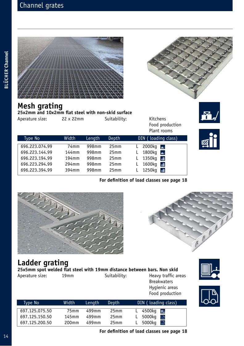
Mesh gratingAperature size: 22 x 22mm Suitability: Kitchens
Food production Plant rooms
Type No Width Length Depth DIN ( loading class)
696.223.074.99 74mm 998mm 25mm L 2000kg 696.223.144.99 144mm 998mm 25mm L 1800kg 696.223.194.99 194mm 998mm 25mm L 1350kg 696.223.294.99 294mm 998mm 25mm L 1600kg 696.223.394.99 394mm 998mm 25mm L 1250kg
For definition of load classes see page 18
Ladder gratingAperature size: 19mm Suitability: Heavy traffic areas
Breakwaters Hygienic areas Food production
Type No Width Length Depth DIN ( loading class)
697.125.075.50 75mm 499mm 25mm L 4500kg 697.125.150.50 145mm 499mm 25mm L 5000kg 697.125.200.50 200mm 499mm 25mm L 5000kg
For definition of load classes see page 18
25x2mm and 10x2mm flat steel with non-skid surface
25x5mm spot welded flat steel with 19mm distance between bars. Non skid
Channel grates
15
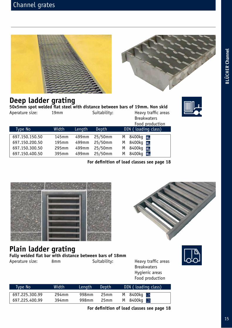
Deep ladder grating50x5mm spot welded flat steel with distance between bars of 19mm. Non skidAperature size: 19mm Suitability: Heavy traffic areas
Breakwaters Food production
Type No Width Length Depth DIN ( loading class)
697.150.150.50 145mm 499mm 25/50mm M 8400kg 697.150.200.50 195mm 499mm 25/50mm M 8400kg 697.150.300.50 295mm 499mm 25/50mm M 8400kg 697.150.400.50 395mm 499mm 25/50mm M 8400kg
For definition of load classes see page 18
Plain ladder gratingAperature size: 8mm Suitability: Heavy traffic areas
Breakwaters Hygienic areas Food production
Type No Width Length Depth DIN ( loading class)
697.225.300.99 294mm 998mm 25mm M 8400kg 697.225.400.99 394mm 998mm 25mm M 8400kg
For definition of load classes see page 18
Fully welded flat bar with distance between bars of 18mm
Channel grates

16
Channel grates
Box section grating25x25x2mm stainless steel box sectionAperature size: 25mm Suitability: Heavy loading
Hygeinic areas
Type No Width Length Depth DIN ( loading class)
697.225.200.99 194mm 998mm 25mm Heavy duty loading Contact Technical Dept 01937 838 000
For definition of load classes see page 18
Wedgewire gratingSuitability: Public areas Showers Swimming pools fire channels
Type No Width Length Depth DIN ( loading class)
697.630.150.99 144mm 998mm 25mm 697.630.200.99 194mm 998mm 25mm
For definition of load classes see page 18
Pedestrian duty Contact technical dept 01937 838 000
V bars nom 5x3mm on nom 13x3mm support bars

17
Channel grates
Type No Width Length Depth DIN ( loading class)
697.250.075.50 75mm 499mm 25mm M 8400kg 697.250.150.50 145mm 499mm 25mm L 6000kg 697.250.200.50 195mm 499mm 25mm M 8400kg
The gratings load class can be specified under various standards and and testing methods. The following are relevant to BLUCHER’s specification of load classes:
DIN 19 599: Gullies and manhole tops for use in buildings.
The grating is tested with a piston , the size of wqhich depends on the grating width (defined as the largest free opening in the outlet/ channel). The free opening is the diameter of the largest circle which can exist between grating supports. As the grating is subjected to various pisto nsizes, it is not always possible to compare the various widths (e.g. a grating with a width of 300mm can be in a higher load class than a grating with a width of 200mm).
The maximum permitted deflection similarly depends on the free opening and is set at 2/500 of the area of the free opening to a maximum of 2mm.
The specified loading in kg for each grating corresponds to the max. loading under the DIN standard.
Description of loading classes:
K (K300) The grating is loaded with 2/3 of 300kg (200kg) five times, with the pressure maintained for 5 min. on the final occasion. The deflection is then measured. Finally the grating is loaded with 300kg. There is no deflection standard on this occasion but the grating must not break and should still be removable.
L (L1500) The grating is loaded with 2/3 of 1500kg (1000kg) five times, with the pressure maintained for 5 min. on the final occasion. The deflection is then measured. Finally the grating is loaded with 1500kg. There is no deflection standard on this occasion, but the grating must not break and should still be removable.
M (M12500) The grating is loaded with 2/3 of 12500kg (8333kg) five times, with the pressure maintained for 5 min. on the final occasion. The deflection is then measured. Finally the grating is loaded with 12500kg. There is no deflection standard on this occasion but the grating must not break and should still be removable.
Description of load classes
Cast stainless gratingnon slip cast grate. ditance between bars of 16-19mmAperature size: 19mm Suitability: Heavy traffic areas
Breakwaters Food production
Barefoot area Pallet trucks Fork lift trucks
Pedestrian traffic Delivery vans / trucks
18
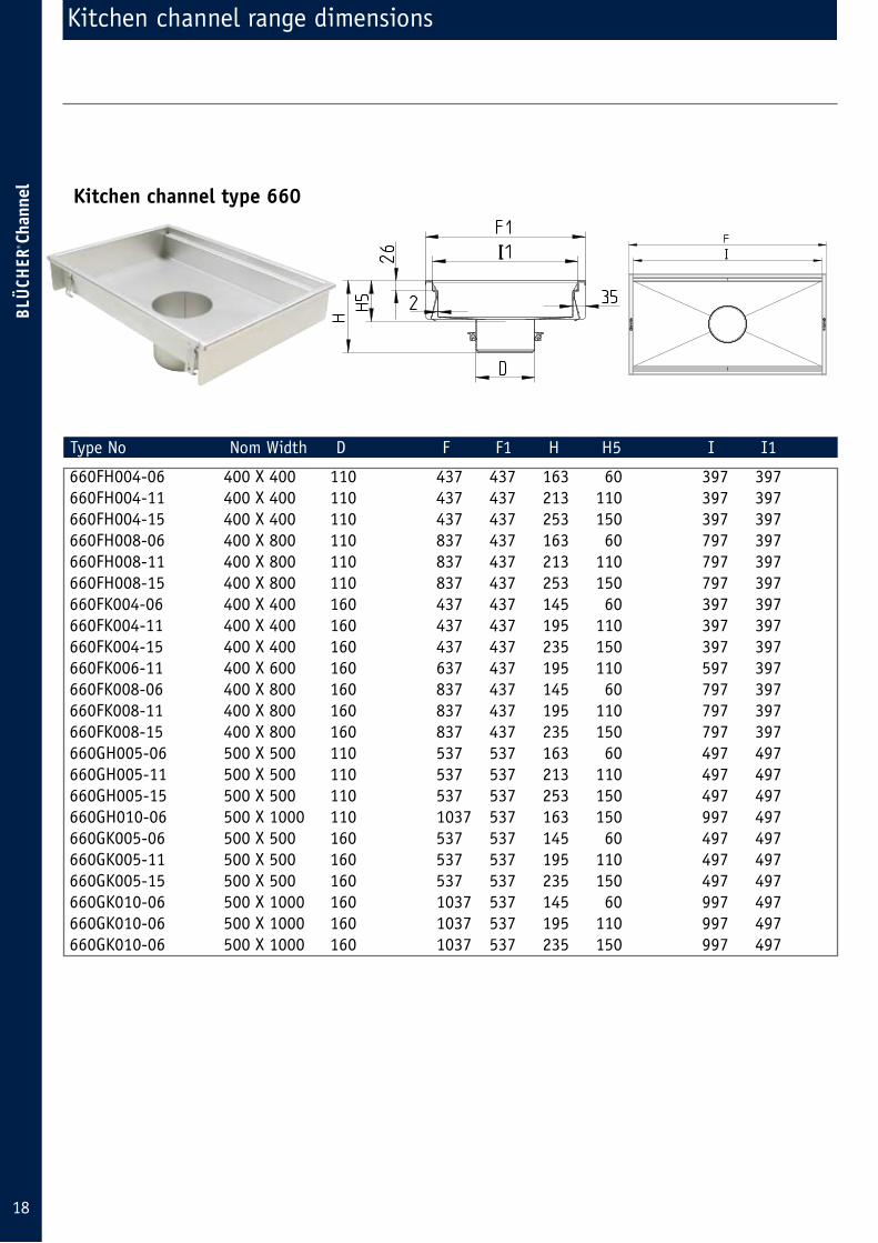
Kitchen channel range dimensions
Type No Nom Width D F F1 H H5 I I1
660FH004-06 400 X 400 110 437 437 163 60 397 397 660FH004-11 400 X 400 110 437 437 213 110 397 397 660FH004-15 400 X 400 110 437 437 253 150 397 397 660FH008-06 400 X 800 110 837 437 163 60 797 397 660FH008-11 400 X 800 110 837 437 213 110 797 397 660FH008-15 400 X 800 110 837 437 253 150 797 397 660FK004-06 400 X 400 160 437 437 145 60 397 397 660FK004-11 400 X 400 160 437 437 195 110 397 397 660FK004-15 400 X 400 160 437 437 235 150 397 397 660FK006-11 400 X 600 160 637 437 195 110 597 397 660FK008-06 400 X 800 160 837 437 145 60 797 397 660FK008-11 400 X 800 160 837 437 195 110 797 397 660FK008-15 400 X 800 160 837 437 235 150 797 397 660GH005-06 500 X 500 110 537 537 163 60 497 497 660GH005-11 500 X 500 110 537 537 213 110 497 497 660GH005-15 500 X 500 110 537 537 253 150 497 497 660GH010-06 500 X 1000 110 1037 537 163 150 997 497 660GK005-06 500 X 500 160 537 537 145 60 497 497 660GK005-11 500 X 500 160 537 537 195 110 497 497 660GK005-15 500 X 500 160 537 537 235 150 497 497 660GK010-06 500 X 1000 160 1037 537 145 60 997 497 660GK010-06 500 X 1000 160 1037 537 195 110 997 497 660GK010-06 500 X 1000 160 1037 537 235 150 997 497
Kitchen channel type 660
I I
19
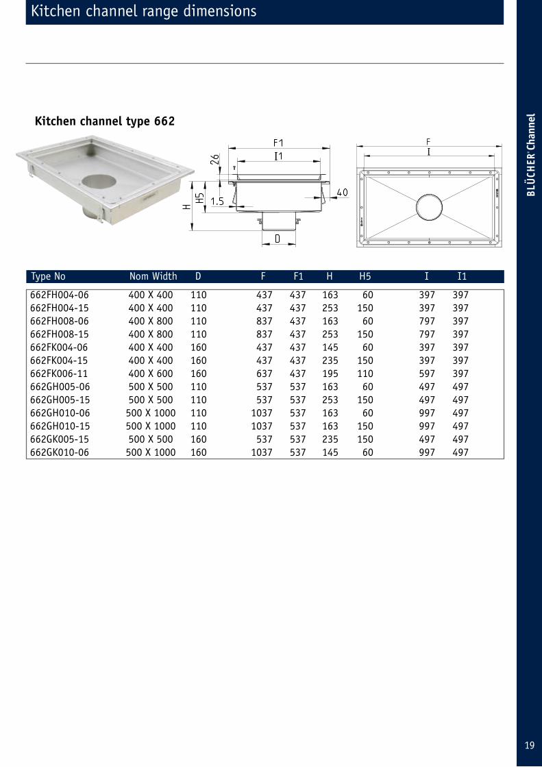
Kitchen channel range dimensions
Kitchen channel type 662
662FH004-06 400 X 400 110 437 437 163 60 397 397 662FH004-15 400 X 400 110 437 437 253 150 397 397 662FH008-06 400 X 800 110 837 437 163 60 797 397 662FH008-15 400 X 800 110 837 437 253 150 797 397 662FK004-06 400 X 400 160 437 437 145 60 397 397 662FK004-15 400 X 400 160 437 437 235 150 397 397 662FK006-11 400 X 600 160 637 437 195 110 597 397 662GH005-06 500 X 500 110 537 537 163 60 497 497 662GH005-15 500 X 500 110 537 537 253 150 497 497 662GH010-06 500 X 1000 110 1037 537 163 60 997 497 662GH010-15 500 X 1000 110 1037 537 163 150 997 497 662GK005-15 500 X 500 160 537 537 235 150 497 497 662GK010-06 500 X 1000 160 1037 537 145 60 997 497
Type No Nom Width D F F1 H H5 I I1
II
20
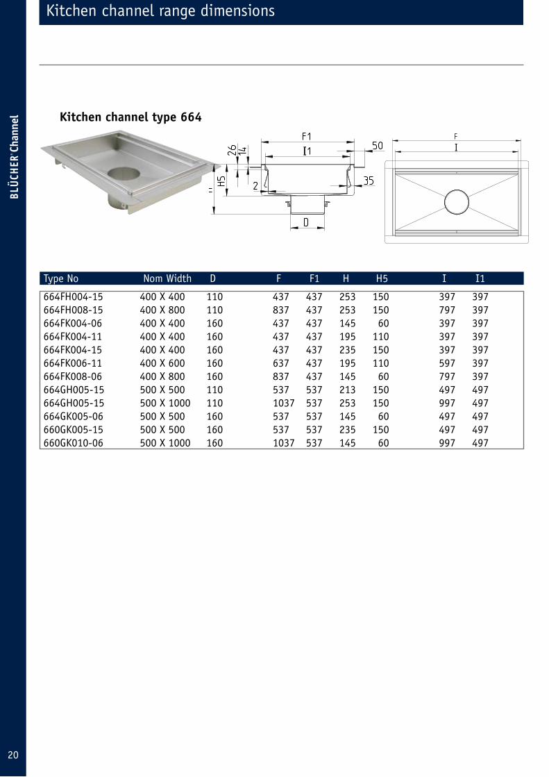
Kitchen channel type 664
664FH004-15 400 X 400 110 437 437 253 150 397 397 664FH008-15 400 X 800 110 837 437 253 150 797 397 664FK004-06 400 X 400 160 437 437 145 60 397 397 664FK004-11 400 X 400 160 437 437 195 110 397 397 664FK004-15 400 X 400 160 437 437 235 150 397 397 664FK006-11 400 X 600 160 637 437 195 110 597 397 664FK008-06 400 X 800 160 837 437 145 60 797 397 664GH005-15 500 X 500 110 537 537 213 150 497 497 664GH005-15 500 X 1000 110 1037 537 253 150 997 497 664GK005-06 500 X 500 160 537 537 145 60 497 497 660GK005-15 500 X 500 160 537 537 235 150 497 497 660GK010-06 500 X 1000 160 1037 537 145 60 997 497
Type No Nom Width D F F1 H H5 I I1
Kitchen channel range dimensions
I I

21
25x2mm and 10x2mm flat steel with non-skid surface
Kitchen channel grates
Mesh grating
Aperature size: 22 x 22mm
Type No Width Length Depth
696.223.394.395 394mm 394mm 25mm 696.223.494.495 494mm 494mm 25mm
Ladder grating
Aperature size: 19mm
Type No Width Length Depth
697.124.400.395 392mm 395mm 25mm 697.125.500.495 492mm 495mm 25mm
25x5mm spot welded flat steel with 19mm distance between bars. Non skid
22
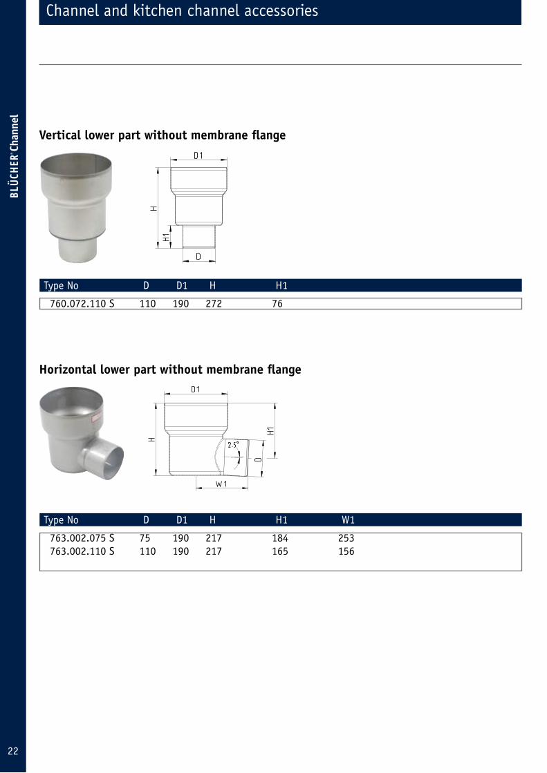
Channel and kitchen channel accessories
Type No D D1 H H1
760.072.110 S 110 190 272 76
Vertical lower part without membrane flange
Type No D D1 H H1 W1
763.002.075 S 75 190 217 184 253 763.002.110 S 110 190 217 165 156
Horizontal lower part without membrane flange

23
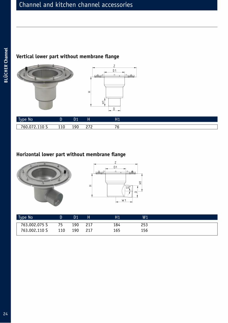
Channel and kitchen channel accessories
Type No D D1 H H1 Z
774.072.075 S 75 190 261 65 409 774.072.110 S 110 190 272 76 409
Vertical lower part with paint on membrane flange
Type No D D1 H H1 W1 Z
769.002.075 S 75 190 217 184 253 409 763.002.110 S 110 190 217 165 156 409
Horizontal lower part with paint on membrane flange
24
Channel and kitchen channel accessories
Type No D D1 H H1
760.072.110 S 110 190 272 76
Vertical lower part without membrane flange
Type No D D1 H H1 W1
763.002.075 S 75 190 217 184 253 763.002.110 S 110 190 217 165 156
Horizontal lower part without membrane flange
25
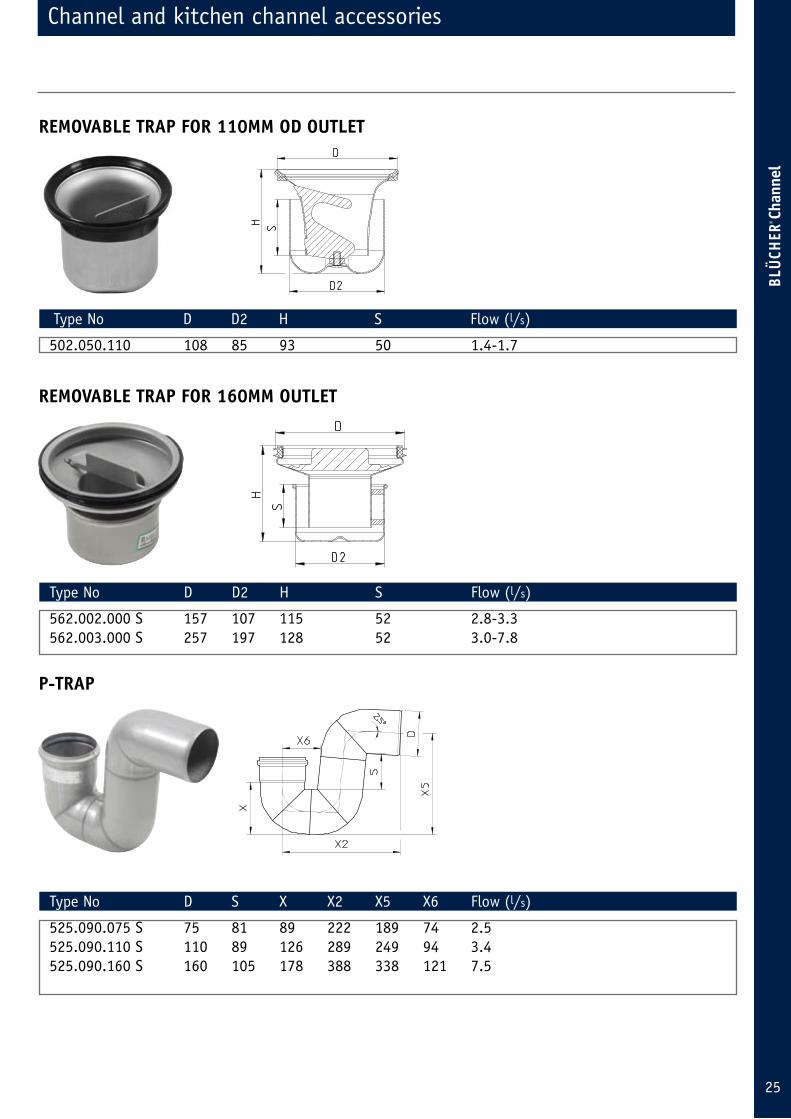
Type No D D2 H S Flow (l/s)
502.050.110 108 85 93 50 1.4-1.7
REMOVABLE TRAP FOR 110MM OD OUTLET
Type No D D2 H S Flow (l/s)
562.002.000 S 157 107 115 52 2.8-3.3 562.003.000 S 257 197 128 52 3.0-7.8
REMOVABLE TRAP FOR 160MM OUTLET
Type No D S X X2 X5 X6 Flow (l/s)
525.090.075 S 75 81 89 222 189 74 2.5 525.090.110 S 110 89 126 289 249 94 3.4 525.090.160 S 160 105 178 388 338 121 7.5
P-TRAP
Channel and kitchen channel accessories
26
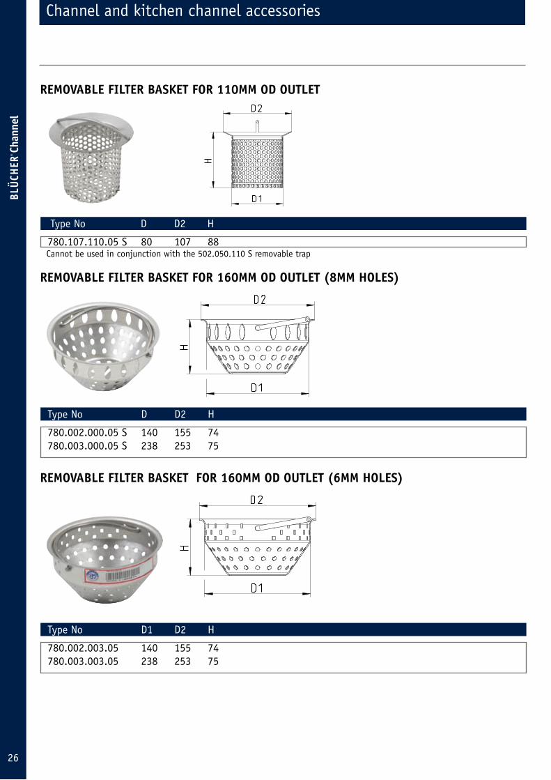
Channel and kitchen channel accessories
Type No D D2 H
780.107.110.05 S 80 107 88
REMOVABLE FILTER BASKET FOR 110MM OD OUTLET
Type No D D2 H
780.002.000.05 S 140 155 74 780.003.000.05 S 238 253 75
REMOVABLE FILTER BASKET FOR 160MM OD OUTLET (8MM HOLES)
Type No D1 D2 H
780.002.003.05 140 155 74 780.003.003.05 238 253 75
REMOVABLE FILTER BASKET FOR 160MM OD OUTLET (6MM HOLES)
Cannot be used in conjunction with the 502.050.110 S removable trap
27
Channel and kitchen channel options and extras
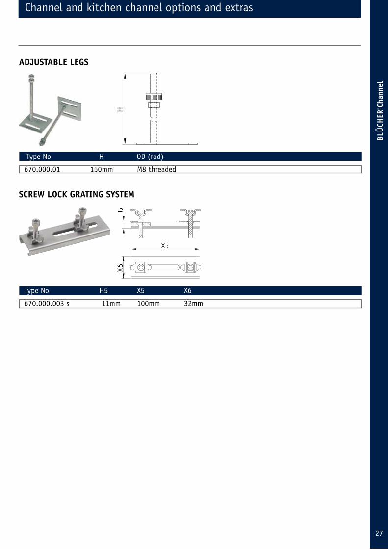
Type No H OD (rod)
670.000.01 150mm M8 threaded
ADJUSTABLE LEGS
Type No H5 X5 X6
670.000.003 s 11mm 100mm 32mm
SCREW LOCK GRATING SYSTEM
28
Channel and kitchen channel options and extras
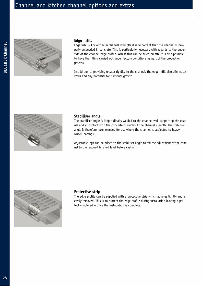
Edge infill Edge infill – For optimum channel strength it is important that the channel is pro-perly embedded in concrete. This is particularly necessary with regards to the under-side of the channel edge profile. Whilst this can be filled on site it is also possible to have the filling carried out under factory conditions as part of the production process.
In addition to providing greater rigidity to the channel, the edge infill also eliminates voids and any potential for bacterial growth.
Stabiliser angleThe stabiliser angle is longitudinally welded to the channel wall supporting the chan-nel and in contact with the concrete throughout the channel’s length. The stabiliser angle is therefore recommended for use where the channel is subjected to heavy wheel loadings.
Adjustable legs can be added to the stabiliser angle to aid the adjustment of the chan-nel to the required finished level before casting.
Protective stripThe edge profile can be supplied with a protective strip which adheres lightly and is easily removed. This is to protect the edge profile during installation leaving a per-fect visible edge once the installation is complete.
CHANNEL
AA
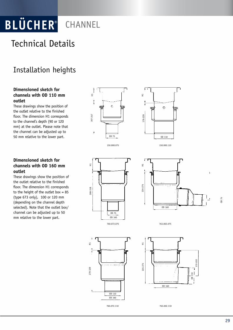
Dimensioned sketch for channels with OD 110 mm outletThese drawings show the position of the outlet relative to the finished floor. The dimension H1 corresponds to the channel’s depth (90 or 120 mm) at the outlet. Please note that the channel can be ad justed up to 50 mm relative to the lower part.
Dimensioned sketch for channels with OD 160 mm outletThese drawings show the position of the outlet relative to the finished floor. The dimension H1 corresponds to the height of the outlet box = 85 (type 673 only), 100 or 120 mm (depending on the channel depth selected). Note that the outlet box/channel can be adjusted up to 50 mm relative to the lower part. OD 160
760.072.075
OD 75
H1
268-
318
OD 160
760.072.110
OD 110
H1
279-
329
OD 1
10
763.002.110
OD 160
H1
172-
222
224-
274
OD 160
763.002.075
H1
224-
274
OD 7
5
H1
H1
197-
247
176-
226
OD 75 OD 110
Installation heights
150.000.075 150.000.110
Technical Details
29
CHANNEL
Cross-bars
Anchor tang
Material quality • Unless otherwise stated, the standard chan-
nel range is made in AISI 304 (EN 1.4301). On request, the channels and most of the gratings and accessories can be supplied in AISI 316L (EN 1.4404) as an option.
• All channels are chemically pickled and passi-vated to provide a clean hygienic surface finish.
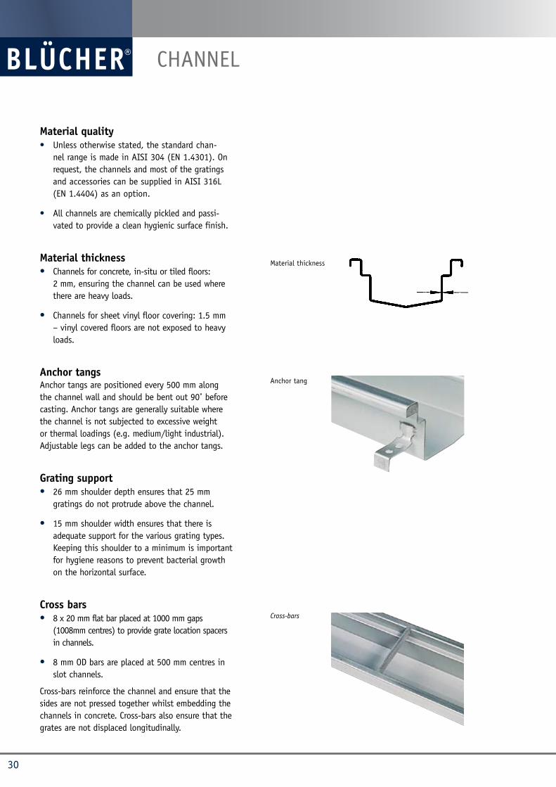
Material thickness • Channels for concrete, in-situ or tiled floors:
2 mm, ensuring the channel can be used where there are heavy loads.
• Channels for sheet vinyl floor covering: 1.5 mm – vinyl covered floors are not expo sed to heavy loads.
Anchor tangs Anchor tangs are positioned every 500 mm along the channel wall and should be bent out 90˚ before casting. Anchor tangs are generally suitable where the channel is not subjected to excessive weight or thermal loadings (e.g. medium/light industrial). Adjustable legs can be added to the anchor tangs.
Grating support• 26 mm shoulder depth ensures that 25 mm
gratings do not protrude above the channel.
• 15 mm shoulder width ensures that there is adequate support for the various grating types. Keeping this shoulder to a minimum is important for hygiene reasons to pre vent bac terial growth on the horizontal sur face.
Cross bars• 8 x 20 mm flat bar placed at 1000 mm gaps
(1008mm centres) to provide grate location spacers in channels.
• 8 mm OD bars are placed at 500 mm centres in slot channels.
Cross-bars reinforce the channel and ensure that the sides are not pressed together whilst embedding the channels in con crete. Cross-bars also ensure that the grates are not displaced longitudinally.
Material thickness
30
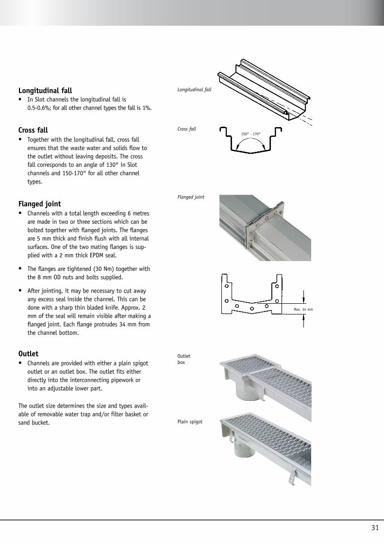
Longitudinal fall• In Slot channels the longi tudinal fall is
0.5-0.6%; for all other channel types the fall is 1%.
Cross fall • Together with the longitudinal fall, cross fall
ensures that the waste water and solids flow to the outlet without leaving deposits. The cross fall corresponds to an angle of 130° in Slot channels and 150-170° for all other channel types.
Flanged joint • Channels with a total length exceeding 6 metres
are made in two or three sections which can be bolted together with flanged joints. The flanges are 5 mm thick and finish flush with all internal surfaces. One of the two mating flanges is sup-plied with a 2 mm thick EPDM seal.
• The flanges are tightened (30 Nm) together with the 8 mm OD nuts and bolts supplied.
• After jointing, it may be necessary to cut away any excess seal inside the channel. This can be done with a sharp thin bladed knife. Approx. 2 mm of the seal will remain visible after making a flanged joint. Each flange protrudes 34 mm from the channel bottom.
Outlet• Channels are provided with either a plain spigot
outlet or an outlet box. The outlet fits either directly into the interconnecting pipework or into an adjustable lower part.
The outlet size determines the size and types avail-able of removable water trap and/or filter basket or sand bucket.
Cross fall150° - 170°
Flanged joint
Longitudinal fall
Plain spigot
Outlet box
Max. 34 mm
31

Room length = L
Room width = B
Channel length = CL
CHANNEL
Calculation of channel lengthWhere there are no special circumstances to be taken into account, the diagrams below can be used as a guide for establishing the correct location and design of channels so that a constant fall is achieved to the drainage channel
As most floors with channels are laid to falls, account must be taken at the planning stage to ensure the fall (A) does not exceed 1-2% (depending on floor type).
B B/2 B/2
B
CL =
L-B
CL =
L-B
CL =
L-B
L
A AA
32
BLÜCHER® channels have proven their functionality and reliability in all kinds of application areas throughout the past four decades. Among the numerous users of BLÜCHER® channels are:
References
33
CS G
rafis
k . 2
000.
06.0
9
2503
2
Co
pyrig
ht b
y BL
ÜCHER
blücher UK lTD · Station road · Tadcaster · lS24 9SG · Tel. 01937 838 000 · Fax 01937 832 454 · [email protected] · www.blucher.co.uk
blücher employs over 300 staff who, through commitment
and know how have developed a range of high quality stainless
steel drainage systems which are sold throughout the world.
For more information on you local supplier log on to
www.blucher.com