bloemsmond solar 4: battery energy storage
TRANSCRIPT

Bloemsmond Solar 4: Battery Energy Storage
DESCRIPTION AND LAYOUT REQUIREMENTS
Prepared for:
Cape Environmental Assessment Practitioners (Pty) Ltd
Date: 7 July 2020
Contact Person:
Dave Peinke Bloemsmond Solar 4 (Pty) Ltd 101, Block A, West Quay Building 7 West Quay Road, Cape Town, 8000 Mobile: + 27 (0) 84 401 9015 Landline: + 27 (21) 418 2596 Email: [email protected]

Bloemsmond Solar 4 (Pty) Ltd ii
DOCUMENT HISTORY
REVISION HISTORY
Revision No Revision Date Author
Draft 7 July 2020 Michael Johnson
Final 7 July 2020 Michael Johnson
APPROVAL FOR RELEASE
Name Title Signed David Peinke Director
DISTRIBUTION
Name Designation Company Dale Holder EAP Cape EAPrac
COPYRIGHT INFORMATION
This document contains intellectual property and proprietary information that is protected by copyright in favour of the author. The document may therefore not be reproduced, used or distributed to any third party without the prior written consent
of the author. This document is subject to all confidentiality, copyright and trade secrets, rules intellectual property law and practices of South Africa.

Bloemsmond Solar 4 (Pty) Ltd iii
TABLE OF CONTENTS
DOCUMENT HISTORY ....................................................................................................... ii
TABLE OF CONTENTS ....................................................................................................... iii
LIST OF FIGURES .............................................................................................................. iv
LIST OF TABLES................................................................................................................ iv
ACCRONYMS AND ABBREVIATIONS .................................................................................. v
1. INTRODUCTION ......................................................................................................... 1
2. UNDERSTANDING THE SOUTH AFRICAN LEGISLATION ................................................ 2
3. OVERVIEW OF THE ENERGY STORAGE FACILITY .......................................................... 3
3.1 TECHNOLOGY ............................................................................................................ 3
3.2 SIZE OF THE BATTERY .............................................................................................. 3
3.3 LOCATION AND SIZE OF THE BATTERY STORAGE AREA ...................................... 4 3.4 GENERAL COMPONENTS ......................................................................................... 5
3.4.1 Battery module/container dimensions ................................................................. 8
3.4.2 Foundation ................................................................................................................ 8
3.4.3 Perimeter Fence........................................................................................................ 8
4. INSTALLATION......................................................................................................... 9 4.1 SEQUENCE ................................................................................................................. 9
4.2 INDICATIVE COSTS .................................................................................................. 10 4.3 INDICATIVE EMPLOYMENT FIGURES ................................................................... 10
5. MAINTENANCE ...................................................................................................... 10
6. DECOMMISSIONING AND DISPOSAL PROCEDURES ............................................ 11
7. SAFETY AND ENVIRONMENT ................................................................................ 11
7.1 GENERAL CARE DURING CONSTRUCTION AND OPERATION ............................ 11
7.2 HIGH VOLTAGE HAZARD RISKS ............................................................................. 11
7.3 OPERATING TEMPERATURE RANGES ................................................................... 12
7.4 THERMAL MANAGEMENT SYSTEMS .................................................................... 12
7.5 RISK OF ELECTROLYTE LEAKAGE ........................................................................... 12
8. CONCLUSION .......................................................................................................... 12
9. LIST OF REFERENCES ................................................................................................ 13
Bloemsmond Solar 4 (Pty) Ltd iv
LIST OF FIGURES
Figure 1: Tesla's Megapack Li-ion Battery (Modular System). ............................................................ 3 Figure 2: The 100 MW/129 MWh Li-ion battery coupled with the Hornsdale wind farm in Australia. ............................................................................................................................................................ 5 Figure 3: Typical Battery System Components. .................................................................................. 6 Figure 4: Typical flow diagram of PV plant with battery storage ....................................................... 6 Figure 5: Pivot Power's proposed 50MW lithium-ion battery in Kemsley, Kent. ............................... 7 Figure 6: A & B) Single Megapack. C) Conceptual design of Megapack BESS containing 160 Megapacks. ......................................................................................................................................... 7 Figure 7: Installation of the 100 MW/129 MWh Li-ion battery at the Hornsdale wind farm............. 9
LIST OF TABLES
Table 1: Battery Sizes. ......................................................................................................................... 4 Table 2: Battery Storage Area. ............................................................................................................ 4

Bloemsmond Solar 4 (Pty) Ltd v
ACCRONYMS AND ABBREVIATIONS
AC Alternating Current
BESS Battery Energy Storage System
CAPEX Capital Expenditure
DC Direct Current
DEA Department of Environmental Affairs
DoE Department of Energy
EIA Environmental Impact Assessment
EOL End of Life
EPC Engineering, Procurement and Construction
HVAC Heating, Ventilating, and Air Conditioning
IPP Independent Power Producer
IRP Integrated Resource Plan
Li Lithium
Li-ion Lithium Ion
LFP Lithium Ion Phosphate
KW Kilowatt
kWh Kilowatt Hour
MW Megawatt
MWh Megawatt Hour
NaS Sodium Sulphur
NCM Lithium Nickel Manganese Cobalt Oxide
NERSA National Energy Regulator of South Africa
O&M Operations & Maintenance
OEM Original Equipment Manufacturer
OPEX Operating Expenditure
PV Photovoltaic(s)
REIPPPP Renewable Energy Independent Power Producer Procurement Programme

Bloemsmond Solar 4 (Pty) Ltd 1
1. INTRODUCTION
South Africa has recognised the need to expand electricity generation capacity within the country.
This is based on national policy and informed by ongoing planning undertaken by the Department
of Energy (DoE) and the National Energy Regulator of South Africa (NERSA).
In recent years, recurring large-scale power cuts (i.e. load shedding) have highlighted the need to
improve reliability and resilience of electricity supply.
The Integrated Resource Plan (IRP 2019) sets the direction for the energy sector, with a shift away
from coal, increased adoption of renewables and gas, and an end to the expansion of nuclear
power. The IRP calls for some 6 000MW of new solar PV capacity and 14 400MW of new wind power
capacity to be commissioned by 2030, as current coal generation capacity will be reduced (by over
80%) by 2050.
One of the main challenges faced by Eskom is managing and balancing electricity demand and
supply. While renewable sources can now achieve lower costs than fossil fuels, photovoltaic (PV)
arrays and wind turbines both have variable electricity production, since they rely on energy inputs
that cannot be controlled (i.e. sunshine and wind). For this reason, fossil fuels currently still have a
key role in the energy sector as they can provide electricity on demand and when consumption
reaches its peak.
However, cost reductions of energy storage technologies and the wider deployment of battery
(particularly lithium-ion) installations globally, have now stimulated interest in combining
renewable energy generation with energy storage to provide dispatchable energy (i.e. energy on
demand) and reliable capacity.
For example, the production peak of PV facilities occurs around noon, whereas electricity demand
normally peaks for about two hours in the morning and two hours in the evening (i.e. when the
population is at home and using electrical appliances). By incorporating energy storage
technologies into renewable energy facilities, the supply of electricity can be controlled by
absorbing/storing during generation peaks and supplying power during demand peaks.

Bloemsmond Solar 4 (Pty) Ltd 2
2. UNDERSTANDING THE SOUTH AFRICAN LEGISLATION
In March 2020, the Department of Environmental Affairs (DEA) clarified the applicability of listed
activities, under the EIA regulations (as amended), which relate to the development and operation
of facilities or infrastructure, for the storage, or storage and handling of a dangerous good, where
such storage occurs in containers in volumes that may meet or exceed the thresholds specified
under the Listing Notices 1, 2 & 3.
As per the DEA’s response, installations, facilities or infrastructure related to the development and
operation (or expansion and operation) of battery energy storage will not trigger any of these listed
activities. Batteries are not regarded as facilities or infrastructure for the storage or storage and
handling of a dangerous good, considering that its inherent purpose or objective is not to store, or
store and handle a dangerous good. Furthermore, a battery is not deemed to be a “container”.
Although a battery will not trigger these listed activities, the following should be noted:
• There may be instances where the battery is not fully assembled and the electrolyte (or
substance making up the electrolyte) intended for the battery, may be stored in a container
on site prior to filling. In these instances, these activities would be applicable as the purpose
would be the storage of that substance (if indeed a dangerous good), and not the storage
of energy.
• Battery storage facilities have the potential to trigger other listed or specified activities. It
is therefore important to consider all other listed and/ or specified activities in the context
of the development and relevant scenario. All listed or specified activities that will be
triggered by the development must be identified, described and assessed in the EIA.
In the case of this application, while other listed activities are triggered, no electrolyte nor
dangerous good will be stored in a container on site in volumes that may meet or exceed the
thresholds specified in EIA regulations. Therefore, activities relating to the storage and handling of
a dangerous good, where such storage occurs in containers, will not be triggered.

Bloemsmond Solar 4 (Pty) Ltd 3
3. OVERVIEW OF THE ENERGY STORAGE FACILITY
3.1 TECHNOLOGY
Unlike conventional energy storage facilities, such as pumped hydro, battery storage has the
advantage of being flexible in terms of site location and sizing. Therefore, they can be incorporated
into, and placed in close proximity, to a wind or solar facility. They also have the advantage of being
easily scaled and designed to meet specific demands.
Different battery storage technologies, such as lithium-ion (Li-ion), zinc hybrid cathode, sodium ion,
flow (e.g. zinc iron or zinc bromine), sodium sulphur (NaS), zinc air and lead acid batteries, can be
used for grid applications. Compared to other battery options, Li-ion batteries are highly efficient,
have a high energy density and are lightweight. As a result of the declining costs, Li-ion technology
now accounts for more than 90% of battery storage additions globally (IRENA, 2019).
Therefore, in line with the above, we propose that Lithium Battery Technologies, such as Lithium
Iron Phosphate (LFP) or Lithium Nickel Manganese Cobalt oxides (NCM), be considered as the
preferred technology.
Figure 1: Tesla's Megapack Li-ion Battery (Modular System).
3.2 SIZE OF THE BATTERY
Our design aims to provide up to five hours of stored energy per day during the demand peaks. The size of the battery will depend on the net output (MWAC) of the PV facility. For example, assuming a 100 MWAC PV plant grid limitation, we could export up to 500 MWh (100MWAC x 5 hours) per day. Hence a 500 MWh battery would be required.
Bloemsmond Solar 4 (Pty) Ltd 4
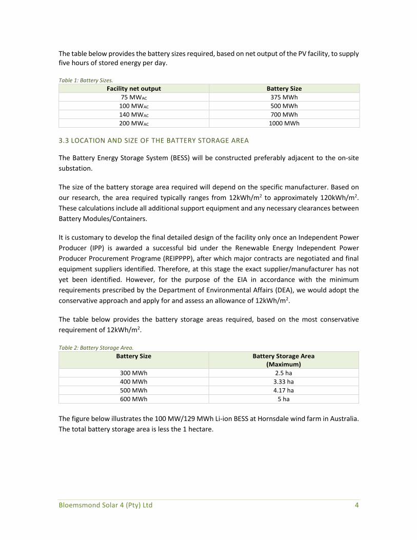
The table below provides the battery sizes required, based on net output of the PV facility, to supply five hours of stored energy per day. Table 1: Battery Sizes.
Facility net output Battery Size
75 MWAC 375 MWh
100 MWAC 500 MWh
140 MWAC 700 MWh
200 MWAC 1000 MWh
3.3 LOCATION AND SIZE OF THE BATTERY STORAGE AREA
The Battery Energy Storage System (BESS) will be constructed preferably adjacent to the on-site
substation.
The size of the battery storage area required will depend on the specific manufacturer. Based on
our research, the area required typically ranges from 12kWh/m2 to approximately 120kWh/m2.
These calculations include all additional support equipment and any necessary clearances between
Battery Modules/Containers.
It is customary to develop the final detailed design of the facility only once an Independent Power
Producer (IPP) is awarded a successful bid under the Renewable Energy Independent Power
Producer Procurement Programe (REIPPPP), after which major contracts are negotiated and final
equipment suppliers identified. Therefore, at this stage the exact supplier/manufacturer has not
yet been identified. However, for the purpose of the EIA in accordance with the minimum
requirements prescribed by the Department of Environmental Affairs (DEA), we would adopt the
conservative approach and apply for and assess an allowance of 12kWh/m2.
The table below provides the battery storage areas required, based on the most conservative
requirement of 12kWh/m2.
Table 2: Battery Storage Area.
Battery Size Battery Storage Area (Maximum)
300 MWh 2.5 ha
400 MWh 3.33 ha
500 MWh 4.17 ha
600 MWh 5 ha
The figure below illustrates the 100 MW/129 MWh Li-ion BESS at Hornsdale wind farm in Australia.
The total battery storage area is less the 1 hectare.

Bloemsmond Solar 4 (Pty) Ltd 5
Figure 2: The 100 MW/129 MWh Li-ion battery coupled with the Hornsdale wind farm in Australia.
3.4 GENERAL COMPONENTS
The exact design will depend on the manufacturer, however traditional utility-scale Li-ion battery
storage facilities include the following main components:
1. Battery cells → modules → packs → racking system (DC).
2. Storage container (HVAC system, thermal management, monitors and controls, fire
suppression, switchgear, and energy management system).
3. Power conversion system (bidirectional inverter to convert AC to DC for battery charging
and DC to AC for discharging).
4. Transformer (to step up 480-V inverter output to 12–66 kV).
Figure 3 illustrates the components that generally make up the primary battery system, Figure 4 is
a typical flow diagram of a PV plant with battery storage and Figure 5 is a conceptual example of a
typical BESS.

Bloemsmond Solar 4 (Pty) Ltd 6
Figure 3: Typical Battery System Components.
Figure 4: Typical flow diagram of PV plant with battery storage

Bloemsmond Solar 4 (Pty) Ltd 7
Figure 5: Pivot Power's proposed 50MW lithium-ion battery in Kemsley, Kent.
In the case of Tesla’s new Megapack Modular System (Figure 6), each Megapack arrives from the
factory fully-assembled and pre-tested in one containerised/modular enclosure—including battery
modules, bi-directional inverters, a thermal management system, an AC main breaker and controls.
No assembly is required on site which significantly reduces complexity and ensures an easy
installation and connection process. These compact modules also increase the energy density of
the battery, reducing the amount of space required (Tesla, 2020). Figure 6 C) is a conceptual design
of a 160 Tesla Megapack BESS. By way of comparison, a 500 MWh BESS (see Table 2 above) would
require in the order of 240 Megapacks.
Figure 6: A & B) Single Megapack. C) Conceptual design of Megapack BESS containing 160 Megapacks.

Bloemsmond Solar 4 (Pty) Ltd 8
3.4.1 Battery module/container dimensions
Based on our research each manufacturer has slightly different individual battery container/module
dimensions, however they all typically fall within the following ranges:
Length: 6m – 12m
Width: 1.5m – 2.5m
Height: maximum of 3m
3.4.2 Foundation
It is likely that the batteries will require a solid foundation/ plinths, such as a concrete pad, grade
beams or a structural steel deck. These will need to be strong enough to support the equipment
and large enough to account for any necessary equipment clearances.
The final foundation design will be undertaken by a relevant qualified civil or structural engineer.
The design will be in accordance with local building standards.
3.4.3 Perimeter Fence
A perimeter fence of approximately 2.1m high will be installed around the BESS. Only authorised
persons will be allowed to enter the BESS.

Bloemsmond Solar 4 (Pty) Ltd 9
4. INSTALLATION
4.1 SEQUENCE
The installation process typically includes the following activities:
1. Site clearing;
2. Site preparation (laying foundations etc.);
3. Delivery (transported to site on a flatbed trailer);
4. Unloading (with the use of cranes and the necessary rigging equipment);
5. Anchoring Containers/ Modules;
6. Wire and cable connections;
7. Commissioning and miscellaneous fine tuning; and
8. Electrical inspection and testing.
It is important to note that this is an iterative process, as can be seen in Figure 7.
Figure 7: Installation of the 100 MW/129 MWh Li-ion battery at the Hornsdale wind farm.

Bloemsmond Solar 4 (Pty) Ltd 10
4.2 INDICATIVE COSTS
The indicative cost of a battery storage system is expected to range between ZAR 5,680 and
ZAR 9,480 per kWh, inclusive of the battery modules/ containers, inverters, controllers, battery
management system, cabling, delivery, warranties and commissioning supervision. For a 400 to
500 MWh BESS, this equates to a range of between ZAR 2.27 billion and ZAR 4.74 billion capital
expenditure (CAPEX), over and above the cost of the conventional solar PV facility.
The indicative installation cost of a battery storage system is expected to range between ZAR 840
and ZAR 2,520 per kWh. For a 400 to 500 MWh BESS, this equates to a range of between ZAR 336
million and ZAR 1.26 billion for the installation, over and above the cost of the conventional solar
PV facility and cost of the battery storage system.
The indicative operating expenditure (OPEX) of the battery storage system is expected to range
between 2 and 3% of CAPEX per annum, therefore between ZAR 45 million and ZAR 142 million per
annum for a 400 to 500 MWh system.
4.3 INDICATIVE EMPLOYMENT FIGURES
It is estimated that the construction of the battery storage system will require a maximum of 50
personnel including the proprietary equipment supplier’s installation and supervisory team. This is
over and above the total Engineering, Procurement and Construction (EPC) workforce required to
construct the solar PV facility. Furthermore, it is expected that a maximum of 5 personnel will be
required to operate and maintain the battery storage system, over and above the Operations &
Maintenance (O&M) workforce required for the solar PV facility.
5. MAINTENANCE
Any maintenance, service or repairs required to be carried out on the proprietary battery storage
equipment will be conducted by the supplier’s personal or their authorised agent. This includes any
preventative maintenance that is identified to be carried out on the plant.
Any necessary maintenance equipment and spares will be kept in the renewable energy facility
general maintenance building and/or storage area. No hazardous or dangerous goods will be stored
in a container on site in volumes that may meet or exceed the thresholds specified in EIA
regulations.
It should be noted that it is highly unlikely that battery modules will be stored on site for strategic
spares purposes. Most Lithium Battery Technologies have a recommended depth of discharge of
80%, meaning that the life of the battery will significantly increase if the depth of each discharge is
limited to 80% of the rated capacity. It is therefore detrimental for battery cells to be stored for
long periods on site, as they may discharge below their recommended limit (potentially down to
100% depth of discharge) and potentially become unusable. It is therefore very likely that battery
modules will be shipped to site on a needs-be basis during operation of the plant.

Bloemsmond Solar 4 (Pty) Ltd 11
6. DECOMMISSIONING AND DISPOSAL PROCEDURES
Lithium battery products contain several recyclable materials (e.g. nickel, cobalt, copper,
aluminium, steel, and lithium), and the majority of proprietary suppliers advocate recycling of their
products. When a battery module reaches its end of life (EOL) or needs to be replaced for a specific
technical reason, it will be returned to the supplier’s facility for disassembly and further processing.
Decommissioning and disposal of batteries will always be in accordance with South African
Regulations. In some cases, batteries will be disposed of without returning to the supplier. In this
instance, local recycling processors may be used adhering to appropriate methods for disposal and
recycling, and where required, under surveillance from the original equipment manufacturer
(OEM).
It must be noted that the specific Lithium Battery Technologies under consideration do not contain
heavy metals such as lead, cadmium, or mercury, which therefore facilitates the safe use and
disposal of these technologies.
Our research shows that the majority of OEMs operate a formal battery recycling plan as they strive
to retrieve all batteries out in the field that have reached EOL for purposes of recycling. These plans
are constantly evolving as OEMs work to further improve their methods of recycling their products.
7. SAFETY AND ENVIRONMENT
7.1 GENERAL CARE DURING CONSTRUCTION AND OPERATION
Batteries are energy storage devices, whether single cell batteries or a collection of battery packs
which assembled with other systems, make up a high-capacity containerised battery solution. As
with most battery products, care should be taken not to short circuit, puncture, crush, immerse,
force discharge or expose to temperatures outside of the recommended safe operating
temperature range of the Lithium Battery Technology. Standard measures will need to be
implemented to ensure the safe installation and operation of battery modules, as well as to prevent
unauthorised entry into the battery storage area during construction and operation.
7.2 HIGH VOLTAGE HAZARD RISKS
A battery storage system poses standard high voltage hazard risks that need to be managed during
construction and operation. A significant high voltage and electrocution risk will exist if the various
equipment enclosures and/or safety circuits are compromised or damaged. A battery pack contains
a substantial electrical charge and can lead to injury or death if mishandled. If a component in the
battery module has been significantly visibly damaged or its enclosure compromised, then it is
recommended to follow appropriate high-voltage preventative measures until the danger has been
assessed by a suitably qualified person.

Bloemsmond Solar 4 (Pty) Ltd 12
7.3 OPERATING TEMPERATURE RANGES
The various Lithium Battery Technologies are designed to operate within recommended safe
operating temperature ranges. The final supplier selection will therefore need to consider site
climatic conditions to ensure the health of the unit. Prolonged exposure to temperatures outside
of the safe operating range can drive battery cells into thermal runaway and result in a fire.
7.4 THERMAL MANAGEMENT SYSTEMS
Lithium Battery Technologies include sealed thermal management systems which contain coolants
and/or refrigerants. Mechanical damage of the sealed thermal management system may result in
leakage of the coolant. Considering that the battery modules are containerised solutions, it is highly
probable that any spillage will occur only within the confines of the enclosure, and therefore pose
a negligible risk of contamination to the environment.
7.5 RISK OF ELECTROLYTE LEAKAGE
There is a very low risk associated with leaked electrolyte from battery cells. This may vary
depending on the specific Lithium Battery Technology. In the case of a Li-ion cell, the electrolyte is
largely absorbed in the electrodes within individual sealed cells. There is therefore little free liquid
electrolyte, and hence a negligible risk of spillage. Should this occur, it would be within the confines
of the enclosure. It is assumed that this would be the case for most Lithium Battery Technologies.
8. CONCLUSION
Renewable energy can currently achieve lower costs than fossil fuels. By incorporating energy
storage technologies into renewable energy facilities, electricity can be stored during generation
peaks and supplied during demand peaks.
Lower costs coupled with improved efficiencies, high energy density, lightweight design and low
environmental risks, make Lithium Battery Technologies the preferred alternative.

Bloemsmond Solar 4 (Pty) Ltd 13
9. LIST OF REFERENCES
Aurecon (2018), Hornsdale Power Reserve - Year 1 Technical and Market Impact Case Study.
Available at: https://www.aurecongroup.com/markets/energy/hornsdale-power-reserve-impact-
study. (Accessed: 30 May 2020).
IRENA (2019), Innovation landscape brief: Utility-scale batteries, International Renewable
Energy Agency, Abu Dhabi.
PV Magazine (2019), Hornsdale Power Reserve appears set for expansion, viewed 30 May
2020, < https://www.pv-magazine-australia.com/2019/11/15/hornsdale-power-reserve-appears-
set-for-expansion/>.
Tesla (2020), Massive Energy Storage Megapack, viewed 30 May 2020, <
https://www.tesla.com/megapack>.
The Tesla Team (2019), Introducing Megapack: Utility-Scale Energy Storage, viewed 29 May
2020, <https://www.tesla.com/blog/introducing-megapack-utility-scale-energy-storage>.
Wärtsilä Corporation (2020), Pivot Power, an EDF Renewables company, places order with Wärtsilä
for 100 MW of energy storage in UK, viewed 29 May 2020,
<https://www.wartsila.com/media/news/25-02-2020-pivot-power-an-edf-renewables-company-
places-order-with-wartsila-for-100-mw-of-energy-storage-in-uk-2648771>.