blender 3d printing essentials - packt publishing ... · blender 3d printing essentials . gordon...
TRANSCRIPT

Blender 3D Printing Essentials
Gordon Fisher
Chapter No. 4 "Making Strong, Light Objects with the
Solidify Modifier"

In this package, you will find: A Biography of the author of the book
A preview chapter from the book, Chapter NO.4 "Making Strong, Light Objects with the Solidify Modifier"
A synopsis of the book’s content
Information on where to buy this book
About the Author Gordon Fisher, as a teenager, studied drafting and built plastic model cars. He got his start in 3D computer modeling back when one would have to create a 3D engineering drawing with a pencil and then input the information into a computer, vertex-by-vertex.
He led a three-person crew in building 3D models of 80 aircraft for the U.S. Army Visual Aircraft Recognition program. He also built an accurate model of the 17th and 18th holes of the Pebble Beach golf course for Callaway Golf's golf simulator. He's currently working with the Open Luna Foundation to create models, X3D and 3D printed, of their parts of their proposed lunar base.
He is the Creative Director at Point Happy Interactive. He has been using Blender professionally since 2002 and has given classes on using Blender and using Python with Blender at Python conferences in Texas and Arkansas. His work has been displayed at the National Air and Space Museum. He is also the author of the book Blender 3D Basics, published by Packt Publishing.
For More Information: www.packtpub.com/blender-3d-printing-essentials/book

I would like to thank all the people who helped me write this book, especially Subho Gupta, the Commissioning Editor, and Amey Sawant, the Project Coordinator. I'd also like to thank Bart Veldhuisen of Blender Nation and Shapeways and Gary Fudge of mCor Technologies for taking the time to answer all my questions, and all the people who have devoted so many hours to developing better and less expensive 3D printers.
For More Information: www.packtpub.com/blender-3d-printing-essentials/book

Blender 3D Printing Essentials You know that 3D printing is hot. You wouldn't have bought this book if you didn't. What I hope you will get from this book is an introduction to building a model in Blender so it will make a good object in a 3D printer.
This is fairly simple. Mostly, you need to know what information the 3D printer needs to make an object, what considerations you need to make when designing your object, and which techniques you can use to achieve your goals.
I have tried to avoid being printer-specific. 3D printing is in the phase where new printers are appearing every day. At some point, there will be a shakeout where the best printer makers prevail, but it's too early to guess which companies those will be. But among all kinds of printers, there are basic rules that will work with any printer, and you will learn how to tailor your objects for particular printers.
While I have worked to ensure that you could do each step demonstrated, I assume that you have a general knowledge of operating Blender, such as one would get from my book Blender 3D Basics, also available on the Packt website.
Let's get started!
What This Book Covers Chapter 1, Designing Objects for 3D Printing, gives you a glimpse into the general issues affecting 3D printing and background on what is going on, so you understand why you may have to do things differently to make an object in Blender for 3D printing than you do for animation or the game engine.
Chapter 2, Measuring and Texturing Techniques for 3D Printing, explains how to prepare a file to be used in 3D printing. We will cover using the Ruler/Protractor tool to measure objects and some methods used in texturing the model.
Chapter 3, Making a Blender Model that's Ready to Print, explains how to make models that are watertight, manifold, and will print well.
Chapter 4, Making Strong, Light Objects with the Solidify Modifier, explains how to make an object strong and light using the Solidify modifier and how to clean up the model. You will also learn about doing precision modeling, dealing with overhangs, and finally you will learn how to export the completed file.
Appendix, contains links to good background material on 3D printing, 3D printing services, hobbyist-level 3D printers, industrial-level 3D printers, and Blender objects available on the web.
For More Information: www.packtpub.com/blender-3d-printing-essentials/book

Making Strong, Light Objects with the Solidify Modifi er
You have started building an object for 3D printing. You were introduced to the 3D Print Toolbox and the Mesh Analysis panel. You learned how to make objects watertight and manifold and fi x any problems with the polygons. Now, it's time to complete the object by making it strong and light using the Solidify modifi er and cleaning up the model. You will also learn about doing precision modeling, dealing with overhangs, and fi nally you will learn how to export the completed fi le.
We'll be covering the following topics in this chapter:
• Optimizing wall thickness• Making an object hollow using the Solidify command• Precision modeling—fi tting two objects together• Dealing with overhangs and support• Exporting to STL and X3D
Optimizing wall thicknessObjects made with 3D printing are all subject to gravity. Failure to take this into consideration will result in objects that break or droop. We already worked a little with that in remodeling the sword, but it's time to take a more in-depth look.
The fi rst thing to do is to fi nd out the minimum wall thickness specifi cations for the material you will be printing in. You can fi nd this information on the Web. It differs for each material. For the dragon, which will be printed in gypsum/sandstone, the minimum thickness is 2 mm for a supported wall and 3 mm for a freestanding wall.
For More Information: www.packtpub.com/blender-3d-printing-essentials/book

Making Strong, Light Objects with the Solidify Modifi er
[ 68 ]
Using Solidify for proper wall thicknessNow it's time to work with the dragon again. It's big, and so we need to do what we can to decrease its volume and reduce the cost. To do that, we will use a modifi er called Solidify. What Solidify does is make a second wall parallel to the original wall, but at an offset. It does a good job, especially on simple objects. But our dragon is pretty complex, with thick and thin parts. So, we are going to have to clean up the model after fi nishing the Solidify operation.
In these following steps, we will investigate the Solidify modifi er, apply it, and separate the inner wall we have just created from the original outer wall:
1. Open up the dragon fi le you were working on in the last chapter. Press Tab to get into Object mode. Select Layer 1 and the dragon.
2. Rotate the view so you can see the front and side of the dragon and center the dragon within the view so you can see it well. In the Blender Properties panel, select the Modifi ers button in the header.
3. Check the eye button for the Solidify modifi er. Suddenly, the dragon looks like it got attacked by a delirious cubist sculptor.
4. Whatever that is, it must be wrong. Open the Solidify modifi er subpanel and check Thickness:. Is it set to 2 mm? Hmmm, that can't be the problem then. Let's fi gure this out.
5. Scroll up in the 3D View window and scroll the Properties panel up until you can see what the Scale: of the dragon is. 10; there's the problem. The modifi er is getting scaled as well as the object, so it's really giving the Solidify command a thickness of 20 mm, and not 2 mm. It's good that this was caught now. When you export a model for 3D printing, its scale must be at 1, 1, 1 or you will have problems getting the printer to print it at the proper size.
6. So, press Ctrl + A or select Object in the 3D View header and navigate to Apply | Scale in the pop-up menus.
7. Now the size of the dragon is the same, but the scaling is 1, 1, 1 and the dragon looks better.
8. Rotate your view of the dragon counter-clockwise and you can see that it has a thickness inside.
9. We need two separate shells, not a solid object. One shell will become the inner surface. The other will become the outer surface. When they are fi nished and joined back together, they will defi ne a solid shape with walls about 2 mm thick, but it is hollow in the center, like a ceramic vase. So look at the Solidify modifi er panel and look at the bottom. Uncheck the Fill Rim checkbox. Now there are two separate surfaces.
For More Information: www.packtpub.com/blender-3d-printing-essentials/book

Chapter 4
[ 69 ]
10. Press the Apply button in the Solidify modifi er panel.11. We need to work on the inner shell, so switch to Edit Mode. Then choose
Mesh from the header of the 3D View window and navigate to Vertices | Separate | By Loose Parts from the pop-up menus.
12. Return to Object Mode. Press Z to change to wireframe shading in the 3D View.
13. Select the inner shell.
Analyzing and modifying the inner shellNow, we must plan what to do to the inner shell of the dragon to prepare it for use as the inner wall of the dragon's body:
• The wing is like an unsupported wall and is pretty large. So, it should be removed from the inner shell to give the greatest strength to the wing of the outer shell.
• The rear foot will be a supporting structure, so it should be strong. It will be removed from the inner shell and the calf is scaled down to strengthen it.
• The front paw is a very large unsupported structure. For the best strength, it will be removed from the inner shell.
• The head has problems; the nose pokes backwards through the outer shell. The horns need all the thickness they can get for strength, so the inner horns must go. The neck, because it will have to support so much weight, must be made thicker.
• The tail needs some rebuilding.
So, let's get started in fi xing up the inner shell. We need to prepare the shell so we can see what we are doing better by giving it a different material than we used for the outer shell:
1. Just to be sure that nothing gets missed, press the Z key to return to solid shading.
2. In the Properties panel, choose the Materials button and open the Materials panel.
3. Click on the minus button to the right-hand side of where it says Dragon Skin to delete that material.
4. Press the New button below that to make a new texture. Name it Dragon Guts and set the Diffuse color as R = 0.224, G = 0.58, and B = 0.00. It is the color selected for the dragon's body in the second chapter. Then, set the Specular Intensity to 0.
For More Information: www.packtpub.com/blender-3d-printing-essentials/book

Making Strong, Light Objects with the Solidify Modifi er
[ 70 ]
5. Now rotate the view and you can see the inner shell and the outer shell. The inner shell is green, but there are a few places where they intersect and you can see the grey of the outer shell. We will have to fi x this.
6. Select the outer shell of the dragon and press M to move it to layer 12.7. Make only layer 1 visible. Press Z to return to wireframe mode. Press 3
on the numpad to get the side view.
The fi rst thing to do to the inner shell of the dragon is to remove the foot and narrow down the calf so the foot can be a load bearing structure as given in the following steps:
1. Select the inner shell of the dragon. Go into Edit Mode and choose Vertex Select. Deselect all the vertices and press Shift + RMB to select all the vertices of the top of the foot as seen in the following screenshot:
2. Press X to delete them. Select Vertices from the pop-up menu.3. Select any vertex on the foot. Press L, which selects linked vertices,
to select all the other vertices on the foot. Press X to delete them.4. Rotate your view so you are looking up at the stump.5. Press Alt + RMB and select the four vertices at the bottom of the stump.
Press F to make a face on it.6. Press Alt + RMB and select the edge loop above the stump. Set the pivot
point to Median Point, press S, and make the calf of the leg narrower.
Next, the inner paw needs to be removed entirely so that the paw will be as strong as possible since it is entirely unsupported. This is illustrated as follows:
1. Pan up to the paw.
For More Information: www.packtpub.com/blender-3d-printing-essentials/book

Chapter 4
[ 71 ]
2. Select the edge loop, one loop from the body, as seen in the following screenshot:
3. Press X to delete the vertices and eliminate the paw as you eliminated the foot.4. Select the edges of the hole where the arm used to be by selecting an edge of
the hole by pressing Alt + RMB.5. Press E Enter and then S 0 Enter. Then press W and choose Remove Doubles
from the pop-up menu. This extrudes a face, scales it to zero, and removes the extra vertices. It's a handy generic way of cleaning up areas of an inner shell.
Now, the wing must be removed from the inner shell. This is similar to removing the paw. This is illustrated as follows:
1. Rotate your view so you can see the wing from the side, as shown in the following screenshot:
For More Information: www.packtpub.com/blender-3d-printing-essentials/book

Making Strong, Light Objects with the Solidify Modifi er
[ 72 ]
2. By pressing Alt + RMB, select the edge loop at the dragon's elbow as seen in the preceding screenshot.
3. Eliminate the wing as you eliminated the foot and paw.4. Next, select the fi ve vertices as shown in the following screenshot and
delete them:
5. Next, by pressing Alt + RMB, select the edges on the perimeter of the hole you have created as seen in the following screenshot:
6. Press E Enter and then S 0 Enter. Then press W and choose Remove Doubles from the pop-up menu.
For More Information: www.packtpub.com/blender-3d-printing-essentials/book

Chapter 4
[ 73 ]
Next, it's time to work on the dragon's head. I mentioned that the nose was a problem, so it will have to be removed. This is illustrated as follows:
1. Press 3 on the numpad and pan the view so you can see the dragon's head.2. Delete the dragon's horns and fi ll the holes.3. Press Ctrl + 3 on the numpad to get the Left Ortho view. Deselect all faces.4. Move the cursor just above and to the left of the nose. Press K and move the
knife tool down with the mouse while holding down the LMB. This shows where the cuts to the faces of the snout will be, as seen on the left-hand side of the following screenshot. Let go of the LMB and then click on the LMB again. Then press Enter to complete the cut.
5. Deselect all vertices and then press B and use the border select to choose all of the vertices to the right of the ones you just cut. Delete them as seen on the right-hand side of the preceding screenshot.
6. Rotate the view so you can see the other side of the dragon's head. Fill in the holes in its upper and lower snout. Make a polygon to cap the end of its snout as seen in the preceding screenshot.
For More Information: www.packtpub.com/blender-3d-printing-essentials/book

Making Strong, Light Objects with the Solidify Modifi er
[ 74 ]
7. Go into Object Mode. Display layers 1 and 12. Set the Viewport Shading to Solid. Inspect the head.
8. There seems to be two places where the inner shell appears through the outer shell as seen in the following screenshot:
9. This shouldn't be. Press Z to get wireframe shading. Rotate your view around the dragon's head. See if you can see what the problem is.
10. I can't see any problem.11. The two shells don't appear to confl ict. Open the Modifi ers panel in the
Properties panel. Darken the eye in the Subsurface modifi er subpanel.12. Select the outer shell and do the same.13. Press Z to get solid shading. Inspect the dragon again. It looks good.
So, there shouldn't be a problem after everything is done.14. Select Layer 1 to display only the inner shell of the dragon once more.
Select the inner shell. Press Z to get wireframe shading and in the Properties panel, click on the eye in the Subsurface subpanel to turn the Subsurface modifi er off.
15. To support the head, the walls of the neck should be extra thick. Set the pivot point to Median Point. Return to Edit Mode.
For More Information: www.packtpub.com/blender-3d-printing-essentials/book

Chapter 4
[ 75 ]
16. Press Alt + RMB and select the fi rst edge loop in the neck, as shown in the following screenshot. Press S 0.6 Enter. This scales the neck to 6/10ths of its former size:
17. Repeat this for the other two edge loops in the neck.
The tail needs a little work. The geometry needs to be smoothed out a bit. Look at the left-hand side of the following screenshot and you will see that there seems to be a valley in the tail instead of it being nicely rounded. The right-hand side of the following screenshot shows a couple of vertices on the very tip of the tail that need to be moved to the left so that they are the same side of the x axis as the rest of the model.
For More Information: www.packtpub.com/blender-3d-printing-essentials/book

Making Strong, Light Objects with the Solidify Modifi er
[ 76 ]
1. Press Ctrl + 1 on the numpad to get the back view. Zoom into the tail.2. For each of the four vertices highlighted in the left of the preceding
screenshot, select it and move it up a little to make a decent curve as shown on the right-hand side of the screenshot.
3. Select the two vertices at the end of the tail, highlighted on the right-hand side of the preceding screenshot, and move them so they are both to the left of center.
4. The second vertex from the right on the bottom of the dragon is a little low. Move it up in line with the others.
5. Press Home and rotate the view so you can see the open side of the dragon.6. Select all the edges on the open side of the dragon with Alt + RMB.7. Press Shift + S and choose Cursor to Center. Set the pivot point to
3D Cursor. Press S X 0 Enter. Now that edge is snapped to the center in the x axis.
8. Now it's time to do a fi nal check on the inner and outer shells of the dragon.9. Switch to Object Mode. Make both Layer 1 and Layer 12 visible. Make the
Subsurface modifi er of both shells visible. Press Z to switch to solid shading.10. Inspect the dragon and make sure that the inner shell does not penetrate the
outer shell. Notice the gap between the shells in the neck area. It's thicker so the neck will be stronger, but there is plenty of room in the inner neck so any excess material inside the head can be shaken out.
11. Press Z to enter wireframe mode, select the inner shell and note the differences between the two models. You've done well.
12. As a precaution, to ensure that the mirror operation will work perfectly on the outer shell of the dragon, select the outer shell of the dragon, go into Edit Mode, and then choose Edge Select. Press Alt + RMB and select the center perimeter of the shell as you did for the inner shell.
13. Press Shift + S and choose Cursor to Center. Set the pivot point to 3D Cursor. Press S X 0 Enter. Return to Object Mode. Save the fi le.
For More Information: www.packtpub.com/blender-3d-printing-essentials/book

Chapter 4
[ 77 ]
Now it's time to put things together. This is illustrated as follows:
1. Select the dragon's inner shell. Open the modifi cations panel of the Properties panel. Make the Mirror modifi er visible. Apply the Mirror modifi er.
2. Make the Subsurface modifi er visible. Apply the Subsurface modifi er.3. Select the dragon's outer shell. Repeat what you did to the inner shell.4. Inspect the two shells.5. Use the Print 3D Toolbox to double check that the shells are solid
and manifold.6. Make sure that Layer 1, Layer 12, and Layer 20 are turned on. Press F12
to render the dragon. It should look just like it did in Chapter 2, Measuring and Texturing Techniques for 3D Printing.
7. Save the fi le to a unique name.
Making the dragon usefulYour dragon is beautiful. Now it is time to make it useful and stick a pencil cup in its back:
1. Press the Esc key to return to the 3D View in the largest window. Display only Layer 1.
2. Select the dragon's inner shell. Go into Edit Mode. In the Mesh Display subpanel, click on the display face normals as lines button. A normal shows you which direction a polygon is facing. Make sure that all the normals are facing outward and that the blue lines used to represent them extend past the inner shell. If they are not, select all the edges and use the Recalculate button in the Tool Shelf. If the normals are not facing outward, the next step will not work right.
3. Return to Object Mode. Open up the Boolean modifi er subpanel. Booleans are very powerful modifi ers. They allow you to control the shape of one object with another object. Here, we are going to use the Boolean modifi er to put a complex depression into the back of the dragon. If you want an in-depth explanation of Boolean operations, check Chapter 8, Making the Sloop of Blender 3D Basics.
For More Information: www.packtpub.com/blender-3d-printing-essentials/book

Making Strong, Light Objects with the Solidify Modifi er
[ 78 ]
4. For the Object, select Pen Cup Boolean Inner Shell. Choose Intersect as the Operation:. Click on the eye button so you can see the Boolean operation. It should look like the following screenshot:
5. Go to Layer 12. Select the dragon's outer shell. Once again, make sure that the normals are facing outwards.
6. Return to Object Mode. Open up the Boolean modifi er subpanel. Choose Pen Cup Boolean Outer Shell as the Object. Choose Intersect as the Operation:. Click on the eye so you can see the Boolean operation.
7. If they both look good, apply the Boolean modifi er to the outer shell. Then go to Layer 1 and apply the Boolean to the inner shell.
8. Press the Tab key to go to Edit Mode. In the Tool Shelf, select Normals: Flip Direction. This will be the inner section of the body, so the normals must point towards the inside instead of the outside as they usually do.
9. Save the fi le so you have a version for a material extrusion printer.
For More Information: www.packtpub.com/blender-3d-printing-essentials/book

Chapter 4
[ 79 ]
Cutting holes for removing extra printing materialIf you are using a printer that uses a powder or liquid for material, you will need to cut holes out of the bottom so that the extra material can be removed. This is not necessary if you are using material extrusion printing like most hobbyist printers:
1. Return to Object Mode. Press Ctrl + 7 on the numpad. Display layer 12. Select the outer shell. Set the Shading to Solid. Go to Edit Mode. Turn off the Normals: display. Display the faces.
2. The printing specifi cation allows us one hole, two holes, or four holes. They are thinking of round holes. In the interest of time, we will make rectangular ones. But remember that stress-wise, round holes are much stronger.
To make round holes, what you do is create a cylinder of the diameter of the holes you want. Line it up where the hole should be; make sure it does not extend up into the pencil cup but does extend below the dragon. Duplicate it, move the duplicate across the x axis, and join the cylinders into a single object.Select the outer shell, make a Boolean modifier, and choose the cylinders as the Boolean object. Use a difference operation, apply it, and then in the dragon, delete the vertices at the top of where the cylinder is inside the dragon. Repeat these steps with the inner shell, but delete the vertices at the bottom of where the cylinder meets the dragon. Then, you connect the holes in a similar manner to the way we connect the rectangular holes.This is what I did for the sample dragon shown at the end of the chapter.
3. For four holes, each hole should be 10 mm in diameter. Use the Ruler /Protractor to measure the width of the central polygons.
For More Information: www.packtpub.com/blender-3d-printing-essentials/book

Making Strong, Light Objects with the Solidify Modifi er
[ 80 ]
4. It turns out that each polygon is about 5 mm on a side. So, to be roughly equal to four 10 mm holes, we need to delete 16 polygons as seen in the following screenshot:
5. Select the faces and delete them.6. Return to Object Mode. Display both Layer 1 and Layer 12. Select the
inner shell and go to Edit Mode.7. Delete the faces in the inner shell that correspond to the holes in the
outer shell.8. Go to Object Mode, press Shift, and select the outer shell as well
as the inner shell.9. Press Ctrl + J to join them. Then press Tab to return to Edit Mode.10. Choose Select Edges. Press Alt + RMB and choose the edges that surround
one hole of the inner shell. Press Shift + Alt + RMB and select the edges that surround that hole of the outer shell as well.
11. From the 3D View header, choose Mesh and then navigate to Edges | Bridge Edge Loops from the pop-up menus. Repeat this with the other hole.
12. Check that the object is solid and manifold. Save your fi le.13. Get into Object Mode. Turn on layers 12 and 20 to display your dragon and
make the camera and lamp active. Do a test render to ensure that all your maps are in place.
Congratulations! Your dragon is done.
For More Information: www.packtpub.com/blender-3d-printing-essentials/book

Chapter 4
[ 81 ]
Precision modeling—fi tting two objects togetherAs a bonus, a tower shaped pencil/pen cup has been provided in layer 6. It can be any material you prefer. But before you go and print it up, you want to make sure it will fi t into the dragons back. The clearance specifi cation for the material that the dragon is made from is 0.9 mm as seen in the following screenshot. This means that there should be a gap of at least 0.9 mm between the dragon and the tower if you want to be sure that they won't bind:
1. Get into wireframe mode. Use your measuring tools to check this. The easiest way in this case would be to just measure the outer width of the pencil cup at its bottom, and the inner width of the cavity in the dragon's back. Make sure that the width of the cavity is at least 1.8 mm (0.18 cm) larger than the width of the pencil cup. If they need to be modifi ed, scale the pencil cup in X or Y as needed.
2. You can scale it in X or Y, then note the scale in the 3D View Properties panel, and scale the pencil cup to the same percentage in the other dimension.
3. Remember what you learned with the scaling of the dragon at the beginning of this chapter. Be sure to apply the scale to the object once it is the proper size. Other materials have different clearance specifi cations, and painting parts and other fi nishing techniques can also affect the clearance. Keep those factors in mind when sizing the tower. Save the fi le to a unique name.
For More Information: www.packtpub.com/blender-3d-printing-essentials/book
Making Strong, Light Objects with the Solidify Modifi er
[ 82 ]
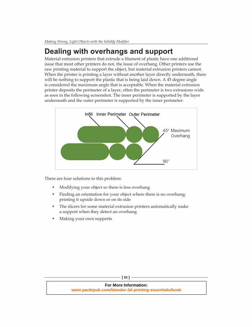
Dealing with overhangs and supportMaterial extrusion printers that extrude a fi lament of plastic have one additional issue that most other printers do not, the issue of overhang. Other printers use the raw printing material to support the object, but material extrusion printers cannot. When the printer is printing a layer without another layer directly underneath, there will be nothing to support the plastic that is being laid down. A 45 degree angle is considered the maximum angle that is acceptable. When the material extrusion printer deposits the perimeter of a layer, often the perimeter is two extrusions wide as seen in the following screenshot. The inner perimeter is supported by the layer underneath and the outer perimeter is supported by the inner perimeter:
There are four solutions to this problem:
• Modifying your object so there is less overhang• Finding an orientation for your object where there is no overhang;
printing it upside down or on its side• The slicers for some material extrusion printers automatically make
a support when they detect an overhang• Making your own supports
For More Information: www.packtpub.com/blender-3d-printing-essentials/book

Chapter 4
[ 83 ]
If the printer automatically makes supportsIf you are using a material extrusion printer that automatically generates supports, here's how to fi nish your object:
1. Open the fi le you saved for a material extrusion printer. Go into Object Mode.
2. Select the inner shell then select the outer shell. Press Ctrl + J to join them.3. Save the fi le to a unique name. You are ready to print.
Making supports for your modelIf you have no other choice, then you must make supports for your model. This is not an exact science and you need to know what the printer you are using can do to span a gap between supports. Your dragon does not need holes in its bottom to shake out extra powder if you are using a material extrusion printer. Nor do material extrusion printers support textures; everything will be the same color:
1. Open the fi le you saved for a material extrusion printer. Go into Object Mode. Select the outer shell.
2. Change to Solid View. Go into Edit Mode. Deselect all of the edges. Turn off the Normals: display. Rotate the view so you can see the bottom of the dragon. Check the Mesh Analysis checkbox in the 3D View properties panel. Set the Type: to Overhang. Set limit the selection to visible. The dragon will look similar to the following screenshot:
For More Information: www.packtpub.com/blender-3d-printing-essentials/book

Making Strong, Light Objects with the Solidify Modifi er
[ 84 ]
If you were making a support for the dragon, the Mesh Analysis would look like the preceding screenshot. The colored areas have all been fl agged for needing support. The tail, bottom, and feet will all be on the printer bed, so they don't need to be supported. The belly, paws, and head do need support:
1. To build a support, fi rst go into Face Select mode. Select a polygon that has been colored red by the Mesh Analysis, say under the dragon's chin. Press I to inset the face and then scale it down to about the smallest size you think the printer can print, as seen on the left-hand side of the following screenshot. This is to make the support easy to break off after you have printed it and minimize the sanding you will need to do.
2. Select the polygon in the center of the inset. Extrude it a little.3. Set the pivot point to Median Point. Scale up the face to a size that you think
can support the weight.4. Extrude it again as seen on the right-hand side of the following screenshot.
Press Shift + S and choose Cursor to Center. Set the pivot point to 3D Cursor. Press S Z 0 Enter to make your support fl at on the bottom and extend down to the printing bed.
5. Now you have a support that goes all the way to the printing bed, as seen in the following screenshot. Make as many as you need to hold up the unsupported part of the object.
6. Go into Object Mode. Select Layer 1 as well as Layer 12. Select the inner shell as well as the outer shell. Press Ctrl + J to join them.
For More Information: www.packtpub.com/blender-3d-printing-essentials/book

Chapter 4
[ 85 ]
7. Save your fi le.
Exporting your 3D objectThere are two kinds of fi les for exporting Blender objects to be printed in 3D; STL fi les and X3D fi les. A few 3D printer companies offer plugins that export Blender fi les to their website as well. STL fi les do not carry any color information. Your color comes from the color material that is chosen as I mentioned in Chapter 1, Designing Objects for 3D Printing. The pencil cup is an example of this. No material was ever specifi ed. It takes its red color from the plastic chosen for printing. X3D fi les are really interactive 3D fi le formats; they carry color information and 3D printing bureaus accept them for printing.
When I am getting ready to export an STL or X3D fi le for 3D printing, I like to put the object(s) to be printed into their own layer of the Blender fi le, usually Layer 1.
For More Information: www.packtpub.com/blender-3d-printing-essentials/book

Making Strong, Light Objects with the Solidify Modifi er
[ 86 ]
Getting the orientation rightYou've used Blender enough to be familiar with Blender's Z-Up axes as shown on the left-hand side of the following diagram:
Many 3D printers use a Y-Up orientation as seen on the right-hand side of the preceding diagram. If the printer you are using is Y-Up orientation, you want to rotate your object 90 degrees in X before exporting it so it will be oriented correctly for printing. To be sure of how they orient their geometry, consult the printing service.
An easy way to orient is to fi rst select the object. Then, set the 3D cursor to center. Set the pivot point to 3D cursor. Press R X 90 Enter to rotate it.
Making an STL fi leSTL fi les do not have any color or texture information. They make all the polygons into triangles so you are guaranteed to have no distorted faces. The best way to double-check your STL fi le is to import your STL fi le back into Blender and see what you have. The STL export process will only export objects that are in a visible layer and selected. Unselected objects in a visible layer will not be exported, nor will anything in a hidden layer.
For More Information: www.packtpub.com/blender-3d-printing-essentials/book

Chapter 4
[ 87 ]
Making STL fi les is easy:
1. Select the object(s) that you want to print and make sure they are visible. The STL export process will only export objects that are in a visible layer and selected. Unselected objects in a visible layer will not be exported, nor will anything in a hidden layer.
2. Select File at the top of the Blender window. Choose Export and STL from the drop-down menus.
3. Select a name for the STL fi le then click on the Export STL button in the upper-right of the window.
4. Follow the uploading directions on your printer's website.
Making an X3D fi le with a textureX3D fi les do have color and texture information. The X3D exporter does not triangulate your polygons. All objects in visible layers will be exported. For X3D fi les, the printing bureau will want a ZIP fi le with both your object fi le and the graphics fi le you using for your texture. Blender does not combine the fi les and zip them up when it exports the fi le. You will have to do it. As stated in Chapter 2, Measuring and Texturing Techniques for 3D Printing, it is best to put the graphic fi le in the same folder as the Blender fi le. X3D fi les can be proofed either by importing them back in Blender or by using an X3D viewer available on the Internet:
1. Choose which layers are visible. Select File at the top of the Blender window.2. Choose Export and X3D Extensible from the drop-down menus.3. Select a name for the X3D fi le then click on the Export X3D button in
the upper-right of the window.4. Then put the .x3d and texture fi les into a zip fi le.5. Follow the uploading directions on the bureau's website.
For More Information: www.packtpub.com/blender-3d-printing-essentials/book

Making Strong, Light Objects with the Solidify Modifi er
[ 88 ]
Summary
As seen in the preceding screenshot, this is what the dragon looks like when it returns from the printer. I customized it a little by coloring the eyes and giving them Anime style double highlights, but leaving the horns green, and I wanted to make the wings look as they are semi-transparent by showing the blood veins.
In this chapter, you discovered how to use the Solidify modifi er to create a solid shell for the object and you learned proper building techniques to make a model strong, light, and precise. You learned how to make sure two objects will fi t together correctly. You discovered how to deal with overhanging polygons, and how to output the fi le in STL and X3D formats. Congratulations and have fun doing 3D printing.
For More Information: www.packtpub.com/blender-3d-printing-essentials/book

Where to buy this book You can buy Blender 3D Printing Essentials from the Packt Publishing website: http://www.packtpub.com/blender-3d-printing-essentials/book. Free shipping to the US, UK, Europe and selected Asian countries. For more information, please read our shipping policy.
Alternatively, you can buy the book from Amazon, BN.com, Computer Manuals and most internet book retailers.
www.PacktPub.com
For More Information: www.packtpub.com/blender-3d-printing-essentials/book