biodiesel test plan - dtic · biodiesel (fatty-acid methyl ester (fame)), hydrogenation-derived...
TRANSCRIPT

Biodiesel Test Plan
Distribution Statement A: Approved for Public Release; distribution is unlimited. July 2014
Report No. CG-D-07-14 (Appendix C)

Biodiesel Test Plan
ii
UNCLAS//Public | CG-926 R&DC | G. W. Johnson, et al.Public | July 2014
N O T I C E
This document is disseminated under the sponsorship of the Department of Homeland Security in the interest of information exchange. The United States Government assumes no liability for its contents or use thereof.
The United States Government does not endorse products or manufacturers. Trade or manufacturers’ names appear herein solely because they are considered essential to the object of this report.
This report does not constitute a standard, specification, or regulation.
Rich Hansen Surface Branch Chief United States Coast Guard Research & Development Center 1 Chelsea Street New London, CT 06320

Biodiesel Test Plan
iii
UNCLAS//Public | CG-926 R&DC | G. W. Johnson, et al.Public | July 2014
Technical Report Documentation Page1. Report No.
CG-D-07-14 (Appendix C) 2. Government Accession Number
3. Recipient’s Catalog No.
4. Title and Subtitle
Biodiesel Test Plan 5. Report Date
July 2014 6. Performing Organization Code
Project No. 4103 7. Author(s)
Gregory W. Johnson, Mark Wiggins, William Remley, Alion Michael Coleman, USCG RDC
8. Performing Organization Report No.
RDC UDI No. 1252
9. Performing Organization Name and Address
U.S. Coast Guard Research and Development Center 1 Chelsea Street, Suite 400 New London, CT 06320
SAIC 23 Clara Drive, Suite 206 Mystic, CT 06355-1959 Alion Science & Technology 1 Chelsea St., Suite 200 New London, CT 06320
10. Work Unit No. (TRAIS)
11. Contract or Grant No.
Contract HSCG32-10-D-R00021/ Task Order HSCG32-11-J-30018 Deliverable No. 3
12. Sponsoring Organization Name and Address
U.S. Department of Homeland Security Commandant (CG-731) United States Coast Guard 2100 Second St. SW Washington, DC 20593-0001
13. Type of Report & Period Covered
Final 14. Sponsoring Agency Code
Commandant (CG-731) U.S. Coast Guard Headquarters Washington, DC 20593-0001
15. Supplementary Notes
The R&D Center's technical point of contact is Michael P. Coleman, 860 271-2708, email: [email protected].
16. Abstract (MAXIMUM 200 WORDS)
This test plan was developed to demonstrate the feasibility of using an alternative fuel in USCG diesel-powered boats. A blend of 100% biodiesel (B100) was selected as the test fuel and a USCG 49’ Buoy Utility Stern Loading (BUSL) boat with Cummins main diesel engines and generator was chosen as the demonstration boat. Testing consists of four phases: materials, bench, field, and operational testing. Materials testing will ensure all components in the engine and fuel system are compatible with B100. Bench testing will ensure the engines operate satisfactorily on B100. Field testing will ensure there are no problems with using B100 on the USCG boat prior to operational testing. Operational testing will ensure there are no problems with using B100 on the test boat over an extended period that encompasses typical operational and environmental factors including cold weather operations. This test plan describes the procedures for the field and operational testing. Prior to commencing field testing, the BUSL engines and fuel systems will be modified in accordance with a Time Compliance Technical Order (TCTO) to ensure compatibility with B100.
17. Key Words 18. Distribution Statement
Biodiesel, CRADA, alternative fuel, Cummins, emissions, BUSL, fatty acid methyl ester (FAME), field test, operational test
Distribution Statement A: Approved for Public Release; distribution is unlimited.
19. Security Class (This Report)
UNCLAS//Public 20. Security Class (This Page)
UNCLAS//Public 21. No of Pages
70 22. Price

Biodiesel Test Plan
iv
UNCLAS//Public | CG-926 R&DC | G. W. Johnson, et al.Public | July 2014
(This page intentionally left blank.)
Biodiesel Test Plan
v
UNCLAS//Public | CG-926 R&DC | G. W. Johnson, et al.Public | July 2014
EXECUTIVE SUMMARY
The Federal Government is placing an emphasis on environmentally friendly and sustainable energy solutions through national initiatives and Federal Government actions. The two main drivers of the use of alternative fuels are 1) the Energy Independence and Security Act (EISA) of 2007 that has a goal of increasing United States (U.S.) energy security by developing renewable fuel production and by improving vehicle fuel economy, and 2) the DHS Strategic Sustainability Performance Plan of June 2011, with a 25 percent greenhouse gas (GHG) reduction goal for the U.S. Coast Guard (CG). Alternative fuels as replacements for the diesel fuel and gasoline in its boat fleet provide the CG with a means to comply with these mandates to reduce the fuel carbon footprint and increase energy independence. The CG Research & Development Center (RDC) contracted with Science Applications International Corporation (SAIC) and Alion Science and Technology (Alion) to develop test plans to demonstrate the feasibility of using alternative fuels in certain CG boats.
A 2010 RDC study (Remley, 2010) identified the most promising alternative fuels for a demonstration as biodiesel (fatty-acid methyl ester (FAME)), hydrogenation-derived renewable diesel (HDRD), and natural gas for the diesel boats; and biobutanol and natural gas for the gasoline-powered boats. The CG selected biodiesel (FAME) as the fuel of choice for the diesel boat demonstration and tasked SAIC and Alion to develop this Biodiesel Test Plan to demonstrate the feasibility of using 100 percent biodiesel fuel (B100) on a CG 49’ diesel-powered Buoy Utility Stern Loading (BUSL) boat. B the BUSL has both Cummins main diesel engines (MDEs) and a Cummins generator, the RDC signed a Cooperative Research and Development Agreement (CRADA) with Cummins for them to provide technical assistance during the testing.
BUSLs are predominantly assigned to CG Aids to Navigation Team (ANT) locations. Alion and SAIC developed this test plan from information gained from site surveys to several ANT locations, inspections of the BUSL engines and fuel systems, interviews with ANT personnel, discussions with a potential biodiesel fuel supplier, a materials audit of the BUSL fuel system, and recommendations from Cummins. The test plan incorporates lessons learned from testing conducted by the U.S. Army Corps of Engineers (USACE), National Oceanographic and Atmospheric Administration’s (NOAA’s) Lake Michigan Field Station (LMFS), and the Washington State Ferries, using B100 and other biodiesel blends in their diesel-propelled floating units.
The RDC selected ANT Long Island Sound (LIS) as the host unit for the testing, in part because they have two BUSLs, making it easier to dedicate one to B100 use. In addition, they are located in the Northeast United States, and are expected to experience some colder weather that will help to capture the full range of environmental conditions over the test period.
This plan contains four testing phases: materials, bench, field, and operational.
Materials testing is conducted to determine the compatibility of the boat and engine fuel system fuel-wetted parts with B100. Alion conducted an audit of fuel system materials/components using the BUSL fuel system diagram and parts list/bill of materials in lieu of actual materials testing because the compatibility of biodiesel with fuel system materials (metallic and non-metallic) is well documented (Donahue, 2012; Leitch et al., 2011a; Leitch et al., 2011b; Nayyar, 2010; NOAA-GLERL, n.d.; Opdal, December 2007). The audit concluded that some fuel system components should be replaced with alternative components that are compatible with B100. The engine original

Biodiesel Test Plan
vi
UNCLAS//Public | CG-926 R&DC | G. W. Johnson, et al.Public | July 2014
equipment manufacturer (OEM), Cummins, performed a similar audit of fuel-wetted engine components and provided its recommendations to the RDC.
Bench testing is typically conducted on a diesel engine in a stationary test cell environment where engine operating parameters, such as fuel consumption, performance, and emissions, are monitored under controlled conditions. Because biodiesel is in current use and its performance is well documented, no bench testing will be required for the BUSL engines.
Field testing is conducted under simulated mission operating conditions, with test personnel monitoring and recording engine and boat performance data to develop baseline data and to diagnose and correct problems before operational testing begins. The RDC will conduct field testing at ANT LIS in summer 2012 using simulated mission operating conditions, with test personnel monitoring and recording engine and boat performance data.
Operational testing will be conducted at ANT LIS over a 12-month period to determine the feasibility of using B100 in CG boats. Ideally, operational testing will begin immediately following field testing, provided no safety concerns or major issues are discovered.
The BUSL engines and fuel system will be prepared and modified to ensure compatibility with the B100 test fuel. The required preparation and modifications will be directed in a Time Compliance Technical Order (TCTO). A draft TCTO is included in this plan and reflects information available at the time of submission. Once materials testing identifies all compatibility issues, the RDC will update the TCTO as needed and submit it for approval. All required modifications will be accomplished prior to the start of field and operational testing with B100.
In addition to the TCTO changes, Alion and SAIC recommend that ANT LIS obtain a waiver of the 95 percent onboard fuel requirement. A waiver will avoid the need to have fuel delivered at the completion of each mission to top off the tanks; instead the fuel could be delivered when the fuel level drops to a lower level, for example 60 percent. This would still leave sufficient fuel to accomplish normal missions, but would reduce the fuel delivery charges by reducing the number of fuel deliveries.

Biodiesel Test Plan
vii
UNCLAS//Public | CG-926 R&DC | G. W. Johnson, et al.Public | July 2014
TABLE OF CONTENTS
EXECUTIVE SUMMARY .......................................................................................................................... V
LIST OF FIGURES ..................................................................................................................................... IX
LIST OF TABLES ....................................................................................................................................... IX
LIST OF ACRONYMS ................................................................................................................................ X
1 INTRODUCTION .................................................................................................................................. 1
2 OVERVIEW OF TESTING .................................................................................................................. 2
2.1 Materials Testing ............................................................................................................................... 2 2.2 Bench Testing ................................................................................................................................... 2 2.3 Field Testing ..................................................................................................................................... 2 2.4 Operational Testing ........................................................................................................................... 2
3 ENGINE INSPECTION/EMISSION TESTING................................................................................. 3
3.1 Test Fuel ............................................................................................................................................ 3 3.2 Engine and Fuel System Inspection .................................................................................................. 6
3.2.1 BUSL Engine Inspection ............................................................................................................ 6 3.2.2 BUSL Fuel System Inspection .................................................................................................... 6
3.3 Emissions Testing ............................................................................................................................. 6 3.4 Lube Oil Testing ............................................................................................................................... 7 3.5 Power and Fuel Consumption ........................................................................................................... 7
4 FIELD/OPERATIONAL TESTING SITE .......................................................................................... 7
4.1 Site Details ........................................................................................................................................ 7 4.2 Fuel Delivery and Storage ................................................................................................................. 9
4.2.1 Fuel Temperature ........................................................................................................................ 9 4.2.2 Delivery and Testing ................................................................................................................. 10
4.3 Boat Modifications and Preparations .............................................................................................. 10
5 TRAINING ............................................................................................................................................ 11
6 DATA COLLECTION PLAN ............................................................................................................. 11
7 TEST PROCEDURES ......................................................................................................................... 15
7.1 Materials Testing ............................................................................................................................. 15 7.2 Bench Testing ................................................................................................................................. 16 7.3 Field Testing ................................................................................................................................... 16
7.3.1 Field Testing Schedule .............................................................................................................. 16 7.3.2 Standard Tests ........................................................................................................................... 17 7.3.3 Pretest Activities ....................................................................................................................... 19 7.3.4 Post-Test Activities ................................................................................................................... 19 7.3.5 Fuel Swaps during Field Testing .............................................................................................. 19 7.3.6 Tank Cleaning Procedure .......................................................................................................... 20

Biodiesel Test Plan
viii
UNCLAS//Public | CG-926 R&DC | G. W. Johnson, et al.Public | July 2014
TABLE OF CONTENTS (Continued)
7.4 Operational Testing ......................................................................................................................... 20 7.4.1 Timeline .................................................................................................................................... 21 7.4.2 ANT LIS Responsibilities ......................................................................................................... 21 7.4.3 Fueling Operations .................................................................................................................... 22 7.4.4 Emergency Fuel Swap Procedures ............................................................................................ 22 7.4.5 Frequent Inspection During Operational Testing ..................................................................... 22 7.4.6 Monthly Visits by RDC ............................................................................................................ 23 7.4.7 Test Conclusion ........................................................................................................................ 23
8 DATA ANALYSIS PLAN .................................................................................................................... 23
8.1 Field and Operational Testing ......................................................................................................... 23
9 SAFETY/FIRE ISSUES ....................................................................................................................... 24
10 REFERENCES ..................................................................................................................................... 25
APPENDIX A BIODIESEL TCTO ....................................................................................................... A-1
APPENDIX B 49’ BUSL CHARACTERISTICS ................................................................................ B-1
APPENDIX C POINTS OF CONTACTS ............................................................................................ C-1
APPENDIX D WATER AND AIR TEMPERATURES FOR NEW HAVEN, CT........................... D-1
APPENDIX E FUEL OPTIONS COST BENEFIT ANALYSIS (CBA) ........................................... E-1
APPENDIX F BUSL FUEL SYSTEM MATERIALS LIST AND ENGINE PARTS LIST ............ F-1
APPENDIX G FIELD TESTING DATA SHEETS ............................................................................. G-1
APPENDIX H SAMPLE OPERATIONAL TESTING DATA SHEET ............................................ H-1

Biodiesel Test Plan
ix
UNCLAS//Public | CG-926 R&DC | G. W. Johnson, et al.Public | July 2014
LIST OF FIGURES
Figure 1. B100 testing timeline. ...................................................................................................................... 4 Figure 2. Biodiesel ASTM specification. ....................................................................................................... 5 Figure 3. Sector LIS. ....................................................................................................................................... 8 Figure 4. 49’ BUSL at Sector LIS. ................................................................................................................. 8 Figure 5. Potential location for B100 fuel storage. ......................................................................................... 9 Figure 6. Data acquisition system for the BUSL. ......................................................................................... 12 Figure 7. Data available from NOAA PORTS (http://tidesandcurrents.noaa.gov/ports). ..................... 13 Figure 8. Data available from NDBC (http://www.ndbc.noaa.gov/). ....................................................... 14
LIST OF TABLES
Table 1. Average biodiesel emissions compared to conventional diesel according to EPA. ......................... 6 Table 2. B100 monitored parameters. ........................................................................................................... 12 Table 3. Field testing schedule (for each phase). .......................................................................................... 17 Table A-1. Recommended changes to BUSL CG49410 to support B100 testing. ..................................... A-2 Table A-2. Cost details for each TCTO item. ............................................................................................. A-4 Table D-1. Average monthly water temperature for Station NWHC3 – 8465705, New Haven, CT. ........ D-1 Table D-2. Air temperatures for New Haven, CT. ..................................................................................... D-1 Table E-1. ANT LIS BUSL (49411) fueling history (Nov 4, 2010 - Nov 4, 2011). ................................... E-1 Table F-1. BUSL fuel system materials list and engine parts list. ............................................................... F-1 Table H-1. Sample operational testing data sheet. ...................................................................................... H-1
Biodiesel Test Plan
x
UNCLAS//Public | CG-926 R&DC | G. W. Johnson, et al.Public | July 2014
(This page intentionally left blank.)

Biodiesel Test Plan
xi
UNCLAS//Public | CG-926 R&DC | G. W. Johnson, et al.Public | July 2014
LIST OF ACRONYMS
ANT Aids to Navigation Team ASTM American Society for Testing and Materials B100 100% biodiesel B20 20% biodiesel blend BUSL Buoy Utility Stern Loading CARB California Air Resource Board CBA Cost Benefit Analysis CFR Code of Federal Regulations CG Coast Guard CO Carbon monoxide COG Course over ground CRADA Cooperative Research and Development Agreement DHS Department of Homeland Security EISA Energy Independence and Security Act EPA Environmental Protection Agency FAME Fatty acid methyl ester GAR Green-Amber-Red GHG Greenhouse gas GPS Global Positioning System HAZMAT Hazardous material HC Hydrocarbon HDRD Hydrogenation-derived renewable diesel Hz Hertz IAW In accordance with kW Kilowatt LIS Long Island Sound LMFS Lake Michigan Field Station LOA Length overall MDE Main diesel engine MPC Maintenance Procedure Card MSDS Material Safety Data Sheet NBB National Biodiesel Board NDBC National Data Buoy Center NM Nautical miles NMEA National Marine Electronics Association NOAA National Oceanographic and Atmospheric Agency NOx Mono-nitrogen oxides (NO and NO2) OD Outside diameter OEM Original equipment manufacturer PM Particulate matter PPE Personal protective equipment psi Pounds per square inch

Biodiesel Test Plan
xii
UNCLAS//Public | CG-926 R&DC | G. W. Johnson, et al.Public | July 2014
LIST OF ACRONYMS (Continued)
R&D Research & Development RDC Research & Development Center RPM Revolutions per minute SAIC Science Applications International Corporation SFLC Surface Forces Logistics Center SOG Speed over ground SOP Standard Operating Procedures SOx Sulfur oxide TCTO Time Compliance Technical Order U.S. United States USACE U.S. Army Corps of Engineers USCG United States Coast Guard

Biodiesel Test Plan
1
UNCLAS//Public | CG-926 R&DC | G. W. Johnson, et al.Public | July 2014
1 INTRODUCTION
The Federal Government is placing an emphasis on environmentally friendly and sustainable energy solutions for national initiatives and Federal Government operations. Executive Order 13514 (2009) requires Federal agencies to quantify, manage, and reduce greenhouse gas (GHG) emissions. The Energy Independence and Security Act (EISA) of 2007 (Energy Public Law 110 - 140, 2007) aims to increase United States (U.S.) energy security by developing renewable fuel production and improving vehicle fuel economy. EISA requires Federal agencies to reduce facility energy intensity by 30 percent by 2015, relative to 2005 levels. Section 142 of EISA requires Federal agencies to achieve at least a 20 percent reduction in petroleum consumption and a 10 percent increase in alternative fuel consumption by 2015, from the 2005 baseline. For the U.S. Coast Guard (CG), the Department of Homeland Security (DHS) Strategy sets a reduction target for Scope 1 and 2 GHG emissions of 25 percent relative to the 2008 baseline by 2020 (DHS Strategic Sustainability Performance Plan, 2011).
The CG, as a protector of the marine environment, intends to be in the forefront of these initiatives by evaluating and adapting solutions that serve to reduce its carbon footprint. One way of complying with the legislative mandates is through the use of alternative fuels as substitutes for currently used gasoline and diesel fuels. Carbon dioxide captured by growing the feedstocks for the alternative fuels reduces overall GHG emissions compared with using similar petroleum-based fuels. A 2010 Research & Development Center (RDC) study (Remley et al., 2010) identified the most promising alternative fuels for a demonstration as biodiesel (fatty-acid methyl ester (FAME)), hydrogenation-derived renewable diesel (HDRD), and natural gas for the diesel boats; and biobutanol and natural gas for the gasoline-powered boats. The RDC contracted with Science Applications International Corporation (SAIC) and Alion Science and Technology (Alion) to develop test plans to demonstrate the feasibility of using alternative fuels in certain CG boats based in part on the recommendations of that report.
The potential benefits of using biodiesel have been demonstrated through testing conducted by the National Oceanographic and Atmospheric Administration’s (NOAA’s) Lake Michigan Field Station (LMFS), and include:
Lower engine exhaust emissions Reduced impact of spilled fuel: biodiesel biodegrades at roughly the same rate as sugar (dextrose)
and more than 3 times more quickly than diesel Renewable energy source Improved health and safety: non-offensive odor, no carcinogens, higher flash point Improved engine performance: biodiesel is a cleaner fuel with a higher cetane number than
conventional diesel fuel, and with higher lubricity properties Reduced system maintenance: biodiesel’s higher lubricity causes less injector and fuel pump wear
The RDC selected a 100 percent biodiesel (B100) fuel for the diesel boat demonstration, and the 49’ Buoy Utility Stern Loading (BUSL) as the platform to be used for this demonstration. The BUSL has two Cummins main diesel engines (MDEs) and a Cummins generator. The RDC has entered into a Cooperative Research and Development Agreement (CRADA) with Cummins to provide technical assistance on their engines. This test plan describes the phased testing that the RDC will carry out to evaluate the suitability of B100 for CG use.

Biodiesel Test Plan
2
UNCLAS//Public | CG-926 R&DC | G. W. Johnson, et al.Public | July 2014
2 OVERVIEW OF TESTING
2.1 Materials Testing
Alion and SAIC developed this test plan from information gained from site survey visits to possible CG testing locations, surveys of candidate boats, discussions with CG personnel, contact with potential fuel suppliers, a materials audit of the boat fuel system, and contact with Cummins, the engine original equipment manufacturer (OEM). It reflects lessons learned through testing conducted by the U.S. Army Corps of Engineers (USACE) (Leitch et al., 2011b), NOAA’s LMFS (n.d.), and the Washington State Ferries (2009) using B100 in their vessels. This test plan details the testing of biodiesel fuel in a 49’ BUSL, and discusses four phases: materials testing, bench testing, field testing, and operational testing.
Materials testing will resolve the compatibility of the boat and engine fuel system fuel-wetted parts with B100. An audit of fuel system materials/components using the BUSL fuel system diagram and parts list/bill of materials was conducted in lieu of actual materials testing because the compatibility of biodiesel with fuel system materials (metallic and non-metallic) is well documented (Donahue, 2010; Fleetguard®, Inc., 2009); Leitch et al., 2011b; Materials Compatibility, (n.d.). The results of this audit identified some parts to be replaced with B100-compatible components. The engine OEM, Cummins, performed a similar audit and provided their recommendations to the RDC. The materials testing section (Section 7.1) discusses the results of the materials audit.
Bench testing would normally be conducted to confirm that diesel engines will run on B100 in a laboratory environment. Bench testing will not be conducted for the BUSL engines because biodiesel is in current use, and its performance is well documented as noted above.
Field testing will be conducted to develop baseline data and diagnose and correct problems before operational testing begins. Field testing will be conducted under simulated mission operating conditions, with test personnel monitoring and recording engine and boat performance data. Field testing will also include crew training with regards to safety considerations and maintenance changes; i.e., different fuel filters or hazardous material (HAZMAT) spill procedures. Field testing will take approximately 1 month beginning in summer 2012, and is discussed in Section 7.3.
Operational testing will be conducted over a 12-month period to determine the feasibility of using B100 in CG boats. BUSLs are predominantly assigned to CG Aids to Navigation Team (ANT) locations, and the BUSL (CG 49010) used for this testing is located at ANT Long Island Sound (LIS). As ANT LIS has two BUSLs assigned, the test boat will operate in a similar manner to the non-test boat, following standard routines as much as possible. Details of operational testing are provided in Section 7.4.
2.2 Bench Testing
2.3 Field Testing
2.4 Operational Testing

Biodiesel Test Plan
3
UNCLAS//Public | CG-926 R&DC | G. W. Johnson, et al.Public | July 2014
The field and operational testing will commence after boat alterations and fuel tank cleaning have been accomplished. The Gantt chart in Figure 1 details the proposed testing schedule that is summarized below:
Field testing: 1 month commencing July 2012 - Phase 1: Testing on diesel fuel to develop baseline data (3-4 days) - Empty and clean tanks; refuel with biodiesel (2 weeks) - Phase 2: Testing on biodiesel to develop comparison data (3-4 days) - Phase 3: Second round of biodiesel testing after 2-3 week static period (3-4 days)
Operational testing commencing September 2012 - Phase 1: Complete seasonal operational testing using B100; September 2012 - May 2013 - Phase 2: Switch to diesel; June 2013 - Phase 3: Switch to B100; July 2013 - Phase 4: Switch to diesel; August 2012
3 ENGINE INSPECTION/EMISSION TESTING
3.1 Test Fuel
A 100 percent biodiesel fuel (B100) will be tested. Biodiesel (FAME) is a petroleum-based diesel fuel replacement or additive made from various feedstocks, such as vegetable oils or waste cooking oil. This non-toxic replacement is most often made from soybean oil through a process called transesterfication, whereby it is mixed with methanol to produce both soy esters and glycerin. Separated from the glycerin, this methyl soyate is considered soy-based biodiesel. Biodiesel is almost a direct replacement for petroleum-based diesel fuel (petrodiesel) with only a minimal loss in horsepower. It can be used in diesel engines with minimal or no engine and/or fuel storage/system modifications. Biodiesel has demonstrated reductions in hydrocarbon (HC), carbon monoxide (CO), sulfur oxide (SOx), and particulate matter (PM) emissions. Biodiesel may biodegrade at a rate as high as 98 percent in 28 days.
Only B100 that meets the American Society for Testing and Materials (ASTM) D6751 Specification (see Figure 2) will be used for testing. The “cloud point” for diesel fuel is the temperature at which the fuel begins to become viscous and difficult to move through fuel lines, filters, injectors, and other engine parts. The cloud point for B100 is determined, in part, by the type of feedstock used in production. In order to ensure satisfactory cold weather operation, only B100 with a cloud point of 32 °F or lower will be used. Biodiesels made from soy or canola feedstocks have cloud points of 32 °F and 26 °F, respectively, and are the preferred options for this testing.

Biodiesel Test Plan
4
UNCLAS//Public | CG-926 R&DC | G. W. Johnson, et al. Public | July 2014
Figure 1. B100 testing timeline.
Biodiesel Test Draft TCTOs complete Test Plans Finalized Install Data Acquisition System BUSL TCTO Approved
Field Testing lnbrief with Command BUSL inspected, ready to go
Field Test Phase 1: baseline BUSL mods implemented BUSL tanks cl.eaned l oad B100
Field Test Phase 2: B100 test 1 Field Test Phase 3: B100 test 2 Evaluate Field Tests ROC Field Test Report- Draft
ROC Field Test Report - Final
Operational Testing Field Tests Passes - Start OperationaJ Test Complete seasonal test of 6 100 Strip tank refuel with diesel Run on diesel fuel Strip tank, refuel with 61 00 Run on 6100 Strip tar1k refuel with diesel Run on diesel fuel Final check on BUSL ROC Operational Test Report - Draft ROC Operational Test Report- Final
Monthly Visits
Monthly Visits 1
Monthly Visits 2
Monthly Visits 3
Monthly Visits 4
Monthly Visits 5
Monthly Visits 6
Monthly Visits 7
Monthly Visits 8
Monthly Visits 9
Monthly Visits 10
Monthly Visits 11
Biobutanol Test
0 days Tue 1131112 Tue 1131/12 0 days Wed 4/4112 Wed 4/4/12 2 wks Fri 6/1112 Thu 6/14/12
0 days Mon 7/16112 Mon 7/16/12
90 daysMon 7/16112Sat 11/17/12 1 day Mon 7/16112 Mon 7116112 1 day Tue 7117112 Tue 7/17/12
5 days Wed 7/18f12 Tue 7124112 2 wks Wed 7125112 Tue Bn/12
5 days Wed 7125112 Tue 7131112 0 days Tue Bfil12 Tue Bn/12 5 days Wed 8/8112 Tue 8/14/12 5 days Wed 9/5112 Tue 9/11112 5 days Wed 9/12112 Tue 9/18112 0 days Thu 10/18f12 Thu 10/18112 Odays Sat 11/17112 Sat11117/12
312 days Tue 9/18112-hu 11128113 Odays Tue 9/18112 Tue 9/18/12
9 emons Tue 9/18/12 Sat 6115113 5days Mon 6/17113 Fri 6121113
1 emon Fri 6121113 Sun 7121/13 5days Mon 7122/13 Fri 7126113
1 emon Fri 7126113 Sun 8125113 5days Mon 8126113 Fri 8/30/13
1 emon Fri 6130f13 Sun 9129/13 Odays Sun 9129113 Sun 9129/13 0 days Sun 9129113 Sun 9129113 0 days Thu 11128113 Thu 11128113
215 days Fri 10/12/12 Fri 819113
0 days F ri 10/12/12 Fri 10/ 12/12
0 days Fri 11/9/12 Fri 11/9/12
0 days Fri 12/14/12 Fri 12/14/12
0 days Fri 1/11/13 Fri 1/11/13
0 days Fr12/8/B Fr12/8/B
o days Fri 3/8/13 Fri 3/8/13
0 days Fri4/12/13 Fri 4/12/13
0 days FriS/10/13 Fri 5/ 10/13
0 days Fri 6/14/13 Fri 6/14/13
0 days Fri 7/12/13 Fri 7/12/13
0 days FriS/9/13 Fri 8/9/13
556 days? Tue 1/31112 Tue 815114
~ Acquisition Directorate Researm & Development Center
AltFuels U!sl1ng 1imehne v2
uarte Nov
• 1/Jl
• 4/4
•
~ 0 0 0 <> 0 0 0 0 0 0 0 • 10/ 12
• 11/ 9
+ U / 14
+1/ll • 2/8
• 3/ 8
+ 4/ U
• 5/10
• 6/ 14
• 7/12
• 8/ 9

Biodiesel Test Plan
5
UNCLAS//Public | CG-926 R&DC | G. W. Johnson, et al.Public | July 2014
Figure 2. Biodiesel ASTM specification.
SPECIFICATION FOR BIODIESEL (B 1 00)- ASTM 06751-09
Nov. 2C08
Biodiesel is defined as the mono alkyl este rs of long chain fatty acids derived from vegeta b le oils or animal fats, for use in compression-ignition (diesel) engines. This specification is For pure (100%) biodiesel prior to use or blending with diese l fuel. #
Property ASTM Method Limits Units
Calcium & Magnesium , combined EN 14538
Flash Point (closed cup) 0 93
Alcohol Control (One of the following must be met)
1. Methanol Content
2. Flash Point
Water & Sediment
Kinematic Viscosity, 40 C
Sulfated Ash Sulfur S 15 Grade S 500 Grade
Copper Strip Corrosion
Cetane
Cloud Point
Carbon Residue 100% sample
Acid Number
Free Glycerin
Total Glycerin
Phosphorus Content
Di sti II ali on, T90 A ET
Sodium/Potassium, combined
Oxidation Stability Cold Soak Filtration
For use in temperatures below -12 C
EN1411 0
093
0 2709
D 445
D 874
0 5453 0 5453
D 130
D 613
0 2500
D 4530*
0 664
0 6584
0 6584
D 4951
D 1160
EN 14538
EN 14112 Annex to 06751 Annex to 06751
5maximum
93minimum
0.2maximum
130 minimum
0.05 maximum
1.9-6.0
0.02 maximum
0.0015 max. (15) 0.05 max. (500)
No. 3 maximum
47minimum
report
0.05 maximum
0.50 maximum
0.020 maximum
0.240 maximum
0.001 maximum
360 maximum
5maximum
3minimum 360maximum 200maximum
BOLD = BQ-9000 Critical Specification Testing Once Production Process Under Control * The carbon residue shall be run on the l CO% sample.
ppm (ug/g)
degrees C
%mass
Degrees C
% vol.
%mass
% mass(ppm) % mass(ppm)
degrees C
%mass
mg KOH/g
%mass
%mass
%mass
degrees C
ppm
hours seconds seconds
# A considerable amo unt of experience exists in the US with a 20% blend of biodiesel with 80% d iesel fuel (B20). Although biodiesel (Bl CO) can be used. blends of over 20% biodiesel with diesel fuel should be evaluated on a case-by-case basis until further experience is available.
~ Acquisition Directorate ~ Researm &: Development Center

Biodiesel Test Plan
6
UNCLAS//Public | CG-926 R&DC | G. W. Johnson, et al.Public | July 2014
3.2 Engine and Fuel System Inspection
3.2.1 BUSL Engine Inspection
Prior to field testing, ANT LIS engineers will inspect and document the condition of engine fuel injectors, fuel pumps, and exhaust valves. The RDC and ANT LIS will discuss the results of the inspection and decide whether to replace any parts. Subject to Cummins and RDC agreement, Cummins will replace the fuel injectors. After the first phase of the field testing (diesel baseline), the components that are not compatible with B100 will be replaced as indicated in the Time Compliance Technical Order (TCTO) (Appendix A).
3.2.2 BUSL Fuel System Inspection
Prior to field testing, ANT LIS engineers will inspect the entire fuel system (fuel lines, valves, hoses, seals, tank connections, and filters) for leaks and satisfactory condition. Components that are not in satisfactory condition will be replaced. After the first phase of the field testing (diesel baseline), the components that are not compatible with B100 will be replaced as indicated in the TCTO (Appendix A). In accordance with recommendations made by USACE (Leitch et al., 2011b), ANT LIS and the RDC test team will visually inspect the engines and fuel system once a month for leaks, seeps, and seal decomposition or degradation.
3.3 Emissions Testing
The Environmental Protection Agency (EPA) (U.S. Environmental Protection Agency, 2002), USACE (Leitch et al., 2011b), and NOAA (Donahue, 2010) have conducted emissions testing with biodiesel, documenting decreased SOx, HC, CO, and PM; while nitrogen oxide (NOx) emissions have increased for the same horsepower. Table 1 compares average biodiesel and petrodiesel emissions as determined by the EPA, using a 20 percent biodiesel blend (B20) to compare with B100.
Table 1. Average biodiesel emissions compared to conventional diesel according to EPA.
Emission Type1 B100 B20
Total Unburned HCs -67% -20% CO -48% -12% PM -47% -12% NOx +10% +2% to -2% 1SOx emissions are essentially eliminated with pure biodiesel. The exhaust emissions of SOx and sulfates (major components of acid rain) from biodiesel are essentially eliminated compared to diesel.
On the BUSL, emissions will first be tested using petrodiesel to establish a baseline for comparison with B100. The RDC will determine the scope of emissions testing, with a goal of measuring NOx, HC, CO, and potentially PM, and following an accepted protocol, such as ISO 8178, EPA Code of Federal Regulations (CFR) 40, or California Air Resource Board (CARB). Preliminary testing may be conducted using a portable emission analyzer measuring only gaseous emissions (omitting the PM measurement) similar to the testing by the USACE (Leitch et al., 2011b).

Biodiesel Test Plan
7
UNCLAS//Public | CG-926 R&DC | G. W. Johnson, et al.Public | July 2014
3.4 Lube Oil Testing
The National Biodiesel Board (NBB) notes (National Biodiesel Board, 2007):
Engine Oil Dilution: Blends higher than B20 may cause a larger amount of unburned fuel to make its way past the piston rings and into the oil pan. This is due to the slightly higher viscosity and the slightly higher density of biodiesel vs. petro diesel. High levels of biodiesel present in the engine oil may polymerize over time and cause serious engine oil sludge problems. Engine oil change intervals may need to be shortened significantly if using high blends of biodiesel. The viscosity and density of B20 and lower blends are very similar to that of the pure petrodiesel, and this phenomenon has not been problematic with blends of B20 or lower so no changes in engine oil intervals are needed with B20 or lower.
The USACE experienced oil sludge problems on one of their boats in engines that were high in usage hours (15,000+) and were due to be overhauled. The biodiesel worked its way into the lube oil, resulting in sludge accumulation. This was initially detected when the engines became hard to start. Because the BUSL engines are lower in usage hours, this problem is not expected during the operational testing. To be cautious, however, the boat engineer will monitor the engine oil on a daily basis when the boat is operating in accordance with Maintenance Procedure Card (MPC) MPC-C-5536. The engineering officer will inform the RDC test team immediately if any lube oil sludge is discovered.
3.5 Power and Fuel Consumption
The USACE report (Leitch et al., 2011b) highlighted the importance of measuring fuel consumption accurately; however, the BUSL does not have any existing fuel flow instrumentation. The RDC will contract a marine technician to install FloScan™ (http://www.FloScan.com/) fuel flow meters on the supply and return fuel lines of the starboard MDE. These are the same devices used by the USACE for their B100 testing. A marine technician will also install a torque monitor to measure shaft horsepower, torque, and revolutions per minute (RPM). Currently, the plan is for Hillhouse Industrial & Marine, based in New Hampshire, to install the torque monitor system.
4 FIELD/OPERATIONAL TESTING SITE
4.1 Site Details
The RDC has selected ANT LIS, located near the mouth of the Quinnipiac River in East Haven, CT (see Figure 3) as the site for field and operational testing. With two BUSLs at ANT LIS, one BUSL will be tested with B100, leaving the other BUSL to run petrodiesel. The second BUSL will not be instrumented as part of the testing, but still will provide a constant baseline for comparison through observations and empirical evidence. The operational and physical characteristics of the 49’ BUSL (see Figure 4) are provided in Appendix B. The RDC has briefed command personnel at ANT and Sector LIS during site visits concerning the objectives, procedures, and timing of the testing. Points of contact for LIS are listed in Appendix C.

Biodiesel Test Plan
8
UNCLAS//Public | CG-926 R&DC | G. W. Johnson, et al.Public | July 2014
Figure 3. Sector LIS.
Figure 4. 49’ BUSL at Sector LIS.
This test plan requires no site modifications at ANT LIS. Figure 5 indicates a potential location for a temporary B100 fuel tank if needed; however, storing the fuel at ANT LIS is not anticipated during testing. A portable tank can be rented if on-site fuel storage is needed, and electrical power would be required to heat the tank during winter months. Section 4.2 addresses fuel logistics, including temperature concerns.

Biodiesel Test Plan
9
UNCLAS//Public | CG-926 R&DC | G. W. Johnson, et al.Public | July 2014
Figure 5. Potential location for B100 fuel storage.
4.2 Fuel Delivery and Storage
The BUSLs located at ANT LIS always refuel on-site. A search for B100 fuel suppliers near ANT LIS identified Biodiesel One Ltd™ located in Southington, CT, about 30 miles from the unit. Biodiesel One uses recycled/waste canola and soy cooking oils, and in January 2012 provided an estimated price for B100 of approximately $3.00/gallon.
4.2.1 Fuel Temperature
With a cloud point ranging from the high 30s to low 20s °F for biodiesel fuel, cold conditions can have adverse effects. At and below the cloud point, the fuel begins to become viscous, and difficult to move through fuel lines, filters, injectors, and other engine parts. Field and operational testing will require B100 with a cloud point of no greater than 32 °F, which typically can be produced from recycled soy or canola-based waste oil. The cloud point of B100 from Biodiesel One varies slightly, but is consistently at or near 32 °F (COMDTINST M16114.22A, 2006). By using virgin soy or canola oils, Biodiesel One could produce a more consistent B100 fuel with a more predictable cloud point; however, the price for such fuel would be about $9.00/gallon due to the higher feedstock cost.
To minimize the effect of low temperature on the fuel, the biodiesel will not be stored on-site. Instead, Biodiesel One will deliver the fuel directly to the BUSL as needed. Existing policy calls for the BUSL to be kept at 95 percent fuel load, which requires refueling after almost every trip. Under this policy, the cost of direct delivery is close to that of setting up an on-site storage facility. If the policy were changed to allow the fuel load to drop as low as 60 percent prior to refueling (which would require a local waiver), the number of fuel deliveries and the overall cost would be considerably lower than the on-site storage option (see Appendix E). A review of past fuel usage showed that the BUSL never used more than 47 percent of tank capacity and typically used much less. Also, because the BUSL trips are planned in advance, the tanks could be filled for a planned long trip, even if not yet down to 60 percent capacity.

Biodiesel Test Plan
10
UNCLAS//Public | CG-926 R&DC | G. W. Johnson, et al.Public | July 2014
Once onboard the BUSL, the B100 is expected to remain above the cloud point. Average water and monthly air temperatures near New Haven are provided in Appendix D. Although the local average daily low air temperatures from December through March are less than 32 ºF, the average water temperature remains above 36 ºF, and much of the BUSL fuel tank surface is exposed to the water. The remaining sides of the tanks are exposed to the ambient temperature in the engine room, which is kept well above the cloud point. In addition, when the engines are operating, heated fuel from the engine is returned to the bottom of the tank (because the fuel is also used as a lubricant, additional fuel is circulated; only about 30 percent is burned, and the rest is returned to the tank). In addition to tracking the flow rate, the FloScan device will measure the fuel temperature as it passes through. This will allow the test team to monitor the fuel temperature during the BUSL winter operations to verify that the fuel remains above the cloud point. External tank heaters will be required if the B100 goes below its cloud point and affects fuel delivery to the engine.
4.2.2 Delivery and Testing
ANT LIS will call Biodiesel One for fuel delivery upon reaching the appropriate fuel level. Biodiesel One has stated that they can deliver within 24 hours. The fuel contract with Biodiesel One will specify that all B100 comply with the ASTM D6751-09 specification with a cloud point of 32 °F or lower, and all fuel deliveries will be accompanied by a certificate of analysis showing compliance. Biodiesel One uses the University of Connecticut for their fuel testing and, in addition, the RDC will require independent fuel testing. The unit will draw a fuel sample at the time of each delivery to examine for clarity (water content) and confirm completion of the independent laboratory analysis. The fuel will be pumped from the delivery truck into the BUSL through a 20 micron or smaller filter to remove any particulates that may be present (this is in accordance with the recommendations of USACE (Leitch et al., 2011b).
4.3 Boat Modifications and Preparations
Based on the materials audit of the boat’s fuel system, and recommendations from earlier tests by the USACE, NOAA, and Washington State Ferries, some modifications and preparations are recommended for the test boat prior to testing. The required actions will be indicated in the approved TCTO, a draft of which is provided in Appendix A. All changes required by the TCTO must be accomplished prior to the start of B100 use; i.e., after the diesel baseline tests are completed. In addition, the modifications will be reversed after testing to return the BUSL to its original configuration. The RDC will determine how the modifications will be accomplished; either by the unit, a commercial contractor arranged by the RDC, or a combination of the two. In addition, the RDC may recommend to Surface Forces Logistics Center (SFLC) not to reverse some of the material compatibility changes, if new information indicates the installed test materials are also compatible with petrodiesel. Cummins has reviewed the BUSL engines (H. Khandelwal, personal communication, 7 December 2011) and does not recommend any major engine adjustments to burn B100, such as an engine teardown or a change in the injector timing. Section 7.1 provides details concerning changes required for materials compatibility with B100.

Biodiesel Test Plan
11
UNCLAS//Public | CG-926 R&DC | G. W. Johnson, et al.Public | July 2014
5 TRAINING
The RDC test team will provide training prior to field testing and operational testing to prepare ANT personnel to use biodiesel on a day-to-day basis. Training will include the following topics (provided in a separate PowerPoint document (Johnson et al., 3/7/2012)).
Project background Project goals; specifically for the biodiesel testing Overview of biodiesel fuel: how it is made, advantages, disadvantages, and the Material Safety Data
Sheet (MSDS) Differences between diesel fuel and biodiesel fuel including the effects of temperature Safety and health-related issues, including regulations concerning exposure to biodiesel, handling,
and emergency procedures such as firefighting Changes in maintenance procedures Changes in Federal and state regulations with respect to spill reporting, etc. Changes in fuel logistics; i.e., biodiesel quality control, fuel quality (Clarity Test), and
ASTM D6751-09 certification Use and monitoring of data acquisition system
6 DATA COLLECTION PLAN
During field and operational testing, dozens of engine and boat parameters will be recorded to document the performance of the Cummins engines using B100. This data will also provide diagnostic information in the event of any failures or performance degradations. The same data will be recorded for both field testing (baseline and B100) and operational testing.
The RDC test team will install an automated data acquisition system (planned for June 2012) prior to the start of the field testing. This system is shown in Figure 6 and is a network of sensors connected to a computer using a National Marine Electronics Association (NMEA) 2000 bus. The SeaPC data acquisition computer will be wired into the 24 volt breaker panel. The data acquisition system encompasses two functional areas: boat dynamics, which consists of data about the boat motion and environment, and engine dynamics, which consists of engine-related parameters. Both areas of data are shown in Table 2.

Biodiesel Test Plan
12
UNCLAS//Public | CG-926 R&DC | G. W. Johnson, et al.Public | July 2014
Figure 6. Data acquisition system for the BUSL.
Table 2. B100 monitored parameters.
Subsystem Parameter Source of Data
Boat Dynamics
BUSL Position WX Station Speed over Ground WX Station Course over Ground WX Station Air Temperature WX Station Wind Speed WX Station Atmospheric Pressure WX Station Humidity WX Station Heading, Pitch, Roll WX Station
Engine Dynamics
Fuel Flow (feed and return) FloScan Fuel Temperature FloScan Shaft RPM, torque, and horsepower ShaftMaster Engine RPM Engine pickup Engine Hours Calculated Engine Temp New sensor Oil Pressure Manual log

Biodiesel Test Plan
13
UNCLAS//Public | CG-926 R&DC | G. W. Johnson, et al.Public | July 2014
The boat dynamics sensor is a PB200 Weather Station that is an integrated collection of sensors. This will be installed on the top of the cabin and wired into the 12 volt panel for power. It provides environmental data (temperature, wind speed, etc.) as well as Global Positioning System (GPS) position, course, speed, and boat roll and pitch. Additional weather and wave data (sea conditions) will be obtained during operational testing from online sources reporting observations from the NOAA PORTS system and the National Data Buoy Center (NDBC) system. Figure 7 and Figure 8 show some of the reporting locations for these two systems in the region where testing will be conducted. The test team will download relevant data from the NOAA websites on a monthly basis and organize it for post-test analysis.
Figure 7. Data available from NOAA PORTS (http://tidesandcurrents.noaa.gov/ports).

Biodiesel Test Plan
14
UNCLAS//Public | CG-926 R&DC | G. W. Johnson, et al.Public | July 2014
Figure 8. Data available from NDBC (http://www.ndbc.noaa.gov/).
The Cummins engine is not computer-controlled, and therefore there is no existing data source to tap into to digitally monitor engine parameters. Instead, engine data will be sent to the SeaPC via sensors installed specifically for the testing. The existing analog FWMurphy instrumentation will not be removed or modified in order to reduce the number of changes made and to retain existing safety features (e.g., the temperature gauge serves also as a safety engine overheating cut-off switch). The RDC will install an additional temperature sensor in the valve cover, which will be connected to the data acquisition system using a Nolan RS-11 NMEA converter. This NMEA converter will also be used to connect the existing tachometer pickup to the data acquisition system.
The RDC will contract a marine technician to install a FloScan fuel monitor system on the starboard MDE. The FloScan output will be converted into NMEA 2000 and input to the SeaPC. The FloScan system consists of two fuel flow meters: one to measure the fuel flow to the engine and one to measure the fuel flow of the return line. The difference between the rates reflects the actual fuel used. The engine hours will be calculated by adding the hours that the tachometer pickup is activated. These calculations will be made during post-test analysis of the data. In addition, the boat engineer will record oil pressure and other standard engine parameters (for all three diesel engines) during the normal engineering rounds.
A commercial contractor will also be hired to install a ShaftMaster 1000 torque monitoring system (starboard shaft only), which will provide shaft RPM, torque, and horsepower. The ShaftMaster system will be integrated into the rest of the data acquisition system using either a serial or Ethernet connection.

Biodiesel Test Plan
15
UNCLAS//Public | CG-926 R&DC | G. W. Johnson, et al.Public | July 2014
Each sensor providing data (engine, weather station, etc.) has different data transmission intervals; some can be controlled while others cannot. The data collection software will be configured to record all data at the intervals that it is received; nominally at 1-second intervals.
The weather station and the data collection computer will each have their own breakers, and energizing these breakers will be part of the boat checks performed by the crew before lighting off the engines. After the breaker is energized, the SeaPC will begin to record data automatically. During the testing, the boat crew will verify that the system is running and report any discrepancies to the RDC test team. The test team will install a touchscreen that will interface with the SeaPC computer in a convenient location for the boat crew to confirm visually that the system is working. The test team will provide pre-test training that will cover the basic operation of the data acquisition system, including how to power it up, how to verify proper operation, and basic troubleshooting. During the monthly unit visits, the test team will collect all data recorded and, if possible, get underway on the BUSL to perform a “check ride” to verify proper operation of the data acquisition system.
7 TEST PROCEDURES
7.1 Materials Testing
In lieu of materials testing, Alion audited the fuel system components and materials for compatibility with the B100 test fuel. Appendix E of the Biodiesel Handling and Use Guide (Connery, 2010) lists metallic and non-metallic materials compatibility with biodiesel. The components in the BUSL fuel system that will be exposed to the B100 (fuel-wetted components) were identified using the BUSL fuel system arrangement drawing and materials list (Barry, 1997) and the BUSL fuel tank cleaning specification (USCG SFLC, 2011). Alion contacted equipment manufacturers for the components that did not have the materials listed to determine suitability for biodiesel use. The audit concluded that the following parts/components are not recommended for B100.
Aeroquip FC 234 flexible fuel hoses (#3 and #51 in Materials List) RACOR 75 duplex fuel filters and 4-way valve (#56 and #57 in Materials List) O-ring in the face seal of the 3/4” outside diameter (OD), weld-type union (#8 in Materials List) Fuel tank hole gaskets made of rubber and cork
Cummins reviewed the fuel-wetted components of the MDE and generator on the BUSL. The fuel pump components and the fuel injectors in the engines (Bosch MW on the C8.3 main engines, and Bosch P7100 on the B3.9 generator engine) have no identified issues with B100, and the fuel supply tubes currently in use are also acceptable. Required changes are limited to the replacement of some washers and gaskets, and a hose. The following parts need to be changed out.
Eight steel rubber-coated sealing washers (5 on the C8.3 Engine and 3 on the B3.9 engine) A zinc-plated banjo connector on the C8.3 engine A flexible ¼” hose on the B3.9 engine
Appendix F provides a complete list of materials/parts/components for the BUSL fuel system, including the list of parts Cummins identified for change out. Cummins will provide replacements for the parts they recommend for change out.

Biodiesel Test Plan
16
UNCLAS//Public | CG-926 R&DC | G. W. Johnson, et al.Public | July 2014
7.2 Bench Testing
The performance of biodiesel in marine use is well documented (Donahue, 2012; Leitch et al., 2011a; Leitch et al., 2011b; Nayyar, 2010; NOAA-GLERL, n.d.; Opdal, December 2007), as B100 and other blends of biodiesel have been tested in marine diesel engines, and are currently being used in some marine diesel engines. Bench testing will not be conducted as part of this project.
7.3 Field Testing
The goals for field testing are:
1. Establish baseline parameters for diesel fuel. 2. Ensure B100 compatibility and functionality in BUSL boat and engine parts. 3. Confirm B100 suitability for operational testing. 4. Compare performance of B100 with baseline diesel fuel performance.
NOTE: At NO TIME will these test procedures or instructions override standard safety practices and
official procedures as defined in COMDTINST M16114.22A, 49’ Buoy Utility Stern Loading BUSL Operator’s Handbook (COMDTINST M16114.22A, 2006), MPCs, specific unit Standard Operating Procedures (SOP), or any CG, Federal, or state laws and regulations. If any test team or unit member believes that part of the test procedure violates any of the above, it is imperative that the member immediately voices his concern to the test team and to the senior engineer present.
7.3.1 Field Testing Schedule
Field-testing is planned for the summer of 2012 and will consist of three phases. Phase 1 will test the BUSL with standard diesel fuel (petrodiesel) to develop baseline data; i.e., performance data using diesel to compare with performance data using B100. Phases 2 and 3 will use B100. Each phase is expected to take 3-4 days.
Phase 1 is scheduled for July 2012 following a Command in-brief. After Phase 1 is completed, ANT personnel will empty the fuel tanks of all diesel fuel (as much as feasible) and a contractor will clean the tanks as per Section 7.3.6. During this time period, ANT personnel or a contractor, as determined by the RDC, will make the TCTO modifications for B100 compatibility. The tanks will be refilled with B100 after they are cleaned. A 2-week period has been allocated to accomplish the tank cleaning and TCTO modifications.
Phase II is planned for August 2012. A 2-3 week period is inserted between Phases 2 and 3 to allow time for the fuel to sit in the tank and to review the data as needed. Phase 3 testing is planned for September 2012.
A set of eight standard tests is defined in Section 7.3.2. These eight tests will be performed for each of the three test phases, with one exception; Test 2 is not required for Phase 1 testing. A sample schedule showing the sequencing and timing of the eight tests is shown in Table 3.

Biodiesel Test Plan
17
UNCLAS//Public | CG-926 R&DC | G. W. Johnson, et al.Public | July 2014
Table 3. Field testing schedule (for each phase).
Time Day 1 Day 2 Day 3 Day 4
0800 In-brief Pre-test checklist Pre-test checklist
WX Make-up
Day
0900 Pre-test checklist Test 3: Slow Speed
(2 hours)
Test 7: Cruise Maneuvers(1 hour)
1000 Test 1: Idle Test
(30 minutes) then inspect
Test 8: Max Speed (2 hours)
1100 Test 4: Slow Speed Maneuvers
(1 hour) 1200 Lunch Lunch Lunch 1300
Test 2: Idle Test (4 hours)
then inspect (not required for Phase 1)
Test 5: Cruise Speed (2 hours)
Outbrief 1400
1500 Test 6: Cruise Maneuvers
(1 hour)
1600
7.3.2 Standard Tests
The eight standards tests to be used for field testing are described below. Data collection worksheets for the tests are included in Appendix G.
7.3.2.1 Test 1: Idle Testing (30 minutes)
After the engines are started, allow them to reach normal operating temperature. Note the time of engine startup and the time that the engines reach operating temperature. Idle the engines for 30 minutes after reaching operating temperature. During this time, the boat engineer will closely observe all fuel system components, looking for leaks, smells, smoke, or any other indication out of the ordinary. Any observations from other personnel present will be reported to the test team and the boat engineer. The boat engineer will make a safety determination concerning any observations and, if an anomaly poses a threat to the crew or to the engine, immediately secure the engines. If the anomaly does not pose imminent danger, the test may continue. After 30 minutes of normal idling, secure the engines.
The boat engineer and the test team will inspect the engines and fuel systems for leaks, recording any abnormalities. If the boat engineer is comfortable with the results of the 30-minute idle test, testing will proceed to Test 2.
7.3.2.2 Test 2: Idle Testing (4 hours)
Note that this test is not required for Phase 1. After the engines are started, allow them to reach normal operating temperature. Note the time of engine startup and the time that the engines reach operating temperature. Idle the engines for 4 hours after reaching operating temperature. During this period, the boat engineer will closely observe all fuel system components, looking for leaks, smells, smoke, or any other indication out of the ordinary. During this test, the test team recommends rotating the boat engineers every 30 to 45 minutes. Any observations from other personnel present will be reported to the test team and the boat engineer. The boat engineer will make a safety determination concerning any observations and, if the anomaly poses a threat to the crew or to the engine, immediately secure the engines. If an anomaly does not pose imminent danger, the test may continue. After the 4 hours of normal idling, secure the engines.

Biodiesel Test Plan
18
UNCLAS//Public | CG-926 R&DC | G. W. Johnson, et al.Public | July 2014
The boat engineer and the test team will inspect the engines and fuel systems for leaks, recording any abnormalities. If the boat engineer is comfortable with the results of the 4-hour idle test, testing will proceed to Test 3. Fuel filters will be checked and replaced if necessary after this test.
7.3.2.3 Test 3: Slow Speed Cruising No Maneuvers (2 hours)
Get underway and proceed to open water where the BUSL can follow a relatively straight course for 2 hours (a slow turn to return home halfway through can be included). Report any abnormalities or safety concerns to the boat engineer and the test team. Record all observations and pay particular attention to the fuel flow, with an emphasis on the consistency and trend in fuel flow. Monitor all other readings and ensure the data collection equipment is running continuously.
7.3.2.4 Test 4: Slow Speed Low Impact Maneuvers (1 hour)
This test is designed to slowly move the biodiesel fuel in the tanks and to ensure that the fuel delivery system on the BUSL can tolerate moderate stress. While underway at slow speed, make large “S” turns to gently rock the BUSL back and forth a maximum of 10 degrees to port and starboard. Perform these large “S” turns for 1 hour. Report any abnormalities or safety concerns to the boat engineer and the test team. Record all observations and pay particular attention to the fuel flow, more importantly its stability and trend. Monitor all other readings and ensure the data collection equipment is running continuously.
7.3.2.5 Test 5: Cruising Speed No Maneuvers (2 hours)
The goal of this test is to make observations and collect data at normal operating speeds. Get underway and proceed to open water where the BUSL can follow a relatively straight course for 2 hours. Bring the BUSL up to its normal cruising speed (approximately 7 knots) and attempt to stay on a constant heading for 2 hours (a slow turn to return home halfway through can be included). Report any abnormalities or safety concerns to the boat engineer and the test team. Record all observations and pay particular attention to the fuel flow, more importantly if fuel flow if inconsistent or decreasing. Monitor all other readings and ensure the data collection equipment is running continuously.
7.3.2.6 Test 6: Cruising Speed Low Impact Maneuvers (1 hour)
This test is designed to move the biodiesel fuel in the tanks and to ensure that the fuel delivery system on the BUSL tolerates moderate stress. While underway at cruising speed, begin to make large “S” turns to gently rock the BUSL back and forth a maximum of 10 degrees to port and starboard. Perform these large “S” turns for 1 hour. Report any abnormalities or safety concerns to the boat engineer and the test team. Record all observations and pay particular attention to the fuel flow, in particular if the fuel flow is inconsistent or decreasing. Monitor all other readings and ensure the data collection equipment is running continuously. Continue this test for 1 hour.
7.3.2.7 Test 7: Cruising Speed Medium Impact Maneuvers (1 hour)
This test is designed to move the biodiesel fuel in the tanks and to ensure that the fuel delivery system on the BUSL can handle a higher level of stress. While underway at cruising speed, begin to make small “S” turns to rock the BUSL back and forth a maximum of 10-20 degrees port and starboard. Perform these small “S” turns for 1 hour. Report any abnormalities or safety concerns to the boat engineer and the test team. Record all observations and pay particular attention to the fuel flow, more importantly if the fuel flow is inconsistent or decreasing. Monitor all other readings and ensure the data collection equipment is running continuously. Continue this test for 1 hour.
Biodiesel Test Plan
19
UNCLAS//Public | CG-926 R&DC | G. W. Johnson, et al.Public | July 2014
7.3.2.8 Test 8: Maximum Speed No Maneuvers Full Power Trial (2 hours)
The goal of this test is to monitor operations while the engine is at its maximum operating speed. Conduct a 2-hour full power trial in accordance with Appendix F of the 49’ Buoy Utility Stern Loading (BUSL) Operator’s Handbook (COMDTINST M16114.22A, July 2006). Appendix G contains the Full Power Trial procedures from the above handbook. Report any abnormalities or safety concerns to the boat engineer and the test team. Record all observations and pay particular attention to fuel flow, more importantly whether the fuel flow is inconsistent or decreasing. Monitor all other readings and ensure the data collection equipment is running continuously.
7.3.3 Pretest Activities
To ensure every test begins with the same baseline, the following tasks will be accomplished prior to all tests in this plan.
1. Boat checks performed by the crew (as per BUSL Handbook/LIS SOP). 2. Normal engine checks performed by the crew (as per BUSL Handbook/LIS SOP). 3. Ensure test data sheet (Appendix G) is filled out and ready for entries including date and time. 4. Ensure data acquisition system has started automatically and is running (no errors on the display)
and logging data. Note: Pre-test training will include operation of the data acquisition system. 5. Record any non-data information; i.e., weather observations, crew personnel list, fuel level, and
miscellaneous information. 6. Ensure RDC observers are in place. 7. Start engines.
7.3.4 Post-Test Activities
The following will be performed by the RDC test team after each test.
1. De-energize the data acquisition system. 2. Ensure that the test form is filled out completely; record observers’ comments if applicable. 3. Confirm test data has been successfully collected (confirm manual observations are captured, and
there are no contrary indications from the data acquisition system). The following checklist will be performed following the last test for the day.
1. Shut down engines. 2. De-energize the data acquisition system. 3. Copy test data onto flash drive. 4. Confirm test data has been successfully copied. 5. Secure all equipment for the night. 6. Ensure that the test form is filled out completely; record observers’ comments if applicable.
7.3.5 Fuel Swaps during Field Testing
Because Phase 1 uses diesel and Phase 2 uses B100, the goal is to empty the tanks as much as possible between the two phases. Because a full tank of diesel will not be needed for the Phase 1 testing, it would be best if the ANT started the field testing with less than a full tank of diesel. At the conclusion of Phase 1, the diesel remaining in the tanks must be pumped out, and returned to the diesel fuel storage tank or transferred to another boat. Any refueling in Phases 2 and 3 will use B100.

Biodiesel Test Plan
20
UNCLAS//Public | CG-926 R&DC | G. W. Johnson, et al.Public | July 2014
7.3.6 Tank Cleaning Procedure
A contractor will clean and strip the tanks after the diesel fuel is removed, and the company involved will have adequate experience in complying with state and Federal laws and guidelines, and will be supervised by the test team and the ANT LIS Engineering Officer.
The following tank cleaning procedure used by the Washington State Ferries (2009) in preparation for their biodiesel testing is recommended. This is provided as a reference only; the contractor will clean the tank in accordance with applicable state and EPA regulations.
Open, empty, and ventilate the tanks. Ensure all fuel suction, fill, sounding, and vent lines are completely drained back to the tank. Visually inspect fuel suction, fill, sounding, and vent lines (if possible) for contamination. Secure all valves to and from the tank and tag out. Have a marine chemist certify tanks as safe for entry and establish the level of personal protective
equipment (PPE) required for safe entry. Have personnel take photographs of tank conditions prior to cleaning. Perform gross removal of
scale and sediments using hand tools if necessary (tile scrapers, flatnose shovels, etc.). If not too dirty, use high pressure hot water to wash all tank surfaces at 3,000 pounds per square inch
(psi) using a hand wand. Pump or vacuum-wash water to a certified storage tank (i.e., vacuum truck) for eventual manifesting and disposal. Collect and remove any additional scale and sediments dislodged in the pressure washing process.
If large quantities of sediment, scale, or slime are found in the tanks, perform a preliminary wash with Zep® Industrial Purple Cleaner and Degreaser, followed by multiple hot water washes.
Squeegee excess water from internal surfaces and remove from tank by pump or vacuum. Wipe all surfaces down with lint-free rags wetted with B100. Have personnel take photographs of tank conditions after cleaning. After final inspection for cleanliness and photo documentation, close tank, install new access hole
gasket (B100-compatible), and prepare to receive fuel.
7.4 Operational Testing
The goal of operational testing is to ensure that B100 can be used successfully as a replacement fuel in an operational setting and to capture any operational and functional differences using B100 as fuel. During the 12-month operational testing, the ANT LIS crews will go about their daily and weekly routine on the test BUSL. Although operational testing is not intended to study and/or resolve the logistics issues associated with obtaining and handling B100, special provisions are needed to supply the fuel required, and are described in Section 7.4.3.
Data collection during the 12 months of operational testing will be accomplished automatically by the data acquisition system and manually via collection of engineer log sheets and test data sheets (Appendix H). The general intent of the operational testing is to follow normal BUSL operations as much as possible. There are, however, some maintenance and fueling procedures specific to the testing, and these are described in Section 7.4.2.

Biodiesel Test Plan
21
UNCLAS//Public | CG-926 R&DC | G. W. Johnson, et al.Public | July 2014
7.4.1 Timeline
The 12-month operational testing period is planned to begin approximately September 2012, immediately following field testing, and will consist of four phases. The data acquisition system installed for field testing will remain installed and functional throughout operational testing.
Phase 1: Starts immediately after field testing is complete, assuming that field testing is successful. Begin daily operations and continue for 9 months using B100 to get a full range of operations and environmental conditions.
Phase 2: Switch back to diesel. This fuel swap is done as a complete fuel swap, so towards the end of Phase 1, the BUSL should be operated so as to end the phase with as little B100 as possible in the tanks.
Pump out the remaining B100 back into the fuel delivery truck. Again, this will not totally empty the fuel tanks, but the goal is to remove as much as possible.
Refill the tanks with standard diesel. Continue normal operations for the month using diesel.
Phase 3: Switch back to B100. This fuel swap is done as a 50-50 swap, so the BUSL should be operated so as to end Phase 2 with about half a tank of diesel remaining.
Reduce fuel level in the tanks to approximately 50 percent full, transferring fuel to another boat as needed.
Fill the tanks with B100. Continue normal operations for the month using B100.
Phase 4: Switch back to diesel. This fuel swap is done as a 50-50 swap so the BUSL should be operated so as to end Phase 3 with about half a tank of B100 remaining.
Reduce fuel level in the tanks to approximately 50 percent full. If needed, Biodiesel One will accept the excess B100 above the 50 percent level, retrieving it in a fuel delivery truck.
Fill the tanks with diesel. Continue normal operations for the month using diesel. Optional final emissions test, to be decided by the RDC. Conclusion of operational testing.
7.4.2 ANT LIS Responsibilities
During the operational testing phase, ANT LIS personnel are to operate within normal operating/training parameters as much as possible, manage fueling operations and fuel swaps, and maintain a heightened vigilance while operating the BUSL to detect any issues that may affect the testing or cause potential harm to the boat or crew. Additional details on these general areas are provided below. Operational commitments and daily and underway routine take precedence over the testing; however, there are some basic test requirements that the boat crews, boat engineers, and Engineering Officer are required to fulfill. These include:
Conduct a visual inspection of the entire fuel system for leaks prior to any underway trips.

Biodiesel Test Plan
22
UNCLAS//Public | CG-926 R&DC | G. W. Johnson, et al.Public | July 2014
Ensure data acquisition system is operating. If the computer is not running, ensure power is connected and try rebooting. If this does not resolve the problem, notify the test team.
Replace filters as necessary (keep all used fuel filters, noting the date and time). Record all maintenance such as fuel filter changes. Immediately contact the RDC and test team leader to report any incidents that may related to the
test; e.g., fuel filter failures, fuel leaks, or engine malfunctions. Fill out operational testing data sheets required by the test plan (Appendix H). Provide copies of all completed operational testing data sheets to RDC representatives during
monthly visits.
7.4.3 Fueling Operations
Fueling procedures will be different for the test BUSL than for the diesel-fueled BUSL at ANT LIS. B100 fuel will be delivered to ANT LIS by tank truck, and pumped through a filter from the truck to the BUSL tanks. The fuel will be delivered with a fuel compliance certificate that will be received by ANT LIS and provided to the RDC. ANT LIS will take a fuel sample, which will be sent to a lab for testing. The RDC will establish a contract and associated procedures for fuel sample testing prior to the start of operational testing.
At the beginning of operational testing, several fueling evolutions may be needed to refine the procedure; issues such as exact placement of the fuel truck, path of the fuel hose, and time allotted will be adjusted as necessary. The Engineering Officer will have final authority with regards to the fueling procedure.
7.4.4 Emergency Fuel Swap Procedures
During the 9-month B100 test, the goal is to use only B100 and every effort must be made to refuel with B100. However, in the event that B100 is not available and operational necessity dictates that the BUSL needs to be refueled, it can be refueled with regular diesel. If this occurs, the minimum amount of diesel possible should be added to the tank. This emergency change of fuel should be noted in the operational testing data sheets (Appendix H) with the exact amount of diesel added, and the RDC should be notified as soon as possible.
7.4.5 Frequent Inspection During Operational Testing
All crew members must be aware that they are operating a B100 test boat, so that there is a heightened sense of vigilance to any potential anomalies and to ensure that procedures specific to the testing are followed. The RDC will provide ample visual reminders such as placards and stickers to be placed on the test BUSL to clearly indicate that it is using B100 as a fuel. These indicators alone, however, should not be relied on to ensure crews are aware.
The boat crew and boat engineer will remain vigilant while underway, monitoring the engines and fuel systems as much as reasonably possible. Any anomalies observed must be noted and any safety concerns must be reported to the Engineering Officer. While underway, any observations that may be safety-related must be immediately brought to the attention of the Coxswain. Even if the anomaly does not appear to be related to the use of the B100, the anomaly will be reported to the RDC and the test team. There may be instances when anomalies appear to be unrelated but ultimately could be attributed to the use of B100 as an alternative fuel.

Biodiesel Test Plan
23
UNCLAS//Public | CG-926 R&DC | G. W. Johnson, et al.Public | July 2014
7.4.6 Monthly Visits by RDC
A test team member will visit ANT LIS during the first week of every month. The purpose of this visit is to ensure all test procedures are being followed, to retrieve data, and to provide an opportunity for the ANT personnel to report any information not recorded via instrumentation. Included in the monthly visit will be a short meeting with the boat crew and engineers to capture any observations during the past month. The test team will document maintenance issues, leaks, or any other noteworthy incidents. Incidents occurring with any regularity are of particular interest to the team (e.g., if the engineers are changing filters with greater frequency than expected). During this visit, the team member will:
Retrieve boat and engine data from the SeaPC and ShaftMaster systems. Ensure all instrumentation is working properly. Repair or replace non-functioning test equipment. Perform a visual inspection of the engine space and fuel system. Talk to boat crew and engineers; record opinions and observations. Retrieve any filters replaced or parts failed. Retrieve copies of all certificates of analysis of delivered B100. Retrieve copies of all completed operational testing data sheets.
Upon return from the monthly visit, the test team member will compile the data, add the data to the master data record, and submit a written report with the results of the visit to the RDC.
7.4.7 Test Conclusion
At the conclusion of operational testing, the test team and ANT LIS will inspect the BUSL to ensure there is no damage to the engines or fuel systems. Cummins will replace the fuel injectors and take them back to the factory for inspection. The test team will remove all test equipment, including the installed data acquisition system. As discussed in Section 4.3, the RDC may recommend to SFLC not to reverse some of the material compatibility changes if new information indicates the installed test materials are also compatible with petrodiesel.
In addition, the test team will hold a wrap-up meeting at ANT LIS. The Engineering Officer and personnel who operated the boat on a routine basis will meet with the test team to review any incidences or anomalies not reported to the test team previously. The wrap-up meeting will also be an opportunity for any final comments or observations to be conveyed to the test team.
8 DATA ANALYSIS PLAN
8.1 Field and Operational Testing
Engine and emissions data collected in the first phase of field testing (diesel operations) will provide a baseline of performance to compare subsequent data. During field and operational testing, engine and fuel consumption data along with course over ground/speed over ground (COG/SOG) information will be used to assess performance while using B100 as compared to performance using diesel. The boat dynamics and weather data will provide a context that can be examined to better understand any trends or anomalies seen in the performance data. In addition, the GPS time-tagging of the data will assist in pinpointing the exact time and location of any performance anomalies. The test team will review testing data at least monthly to detect any performance changes. The review will consist of analyzing the engine and fuel consumption data along with the COG/SOG information and comparing the results back to the baseline data.
Biodiesel Test Plan
24
UNCLAS//Public | CG-926 R&DC | G. W. Johnson, et al.Public | July 2014
9 SAFETY/FIRE ISSUES
Biodiesel poses a lower health and safety hazard than petroleum diesel. All standard USCG and ANT LIS safety and fire precautions will remain in effect. The safety and environmental aspects of biodiesel are:
Toxicity: pure biodiesel is non-toxic. Non-offensive odor No carcinogens Explosive: biodiesel, while still dangerous, is far less volatile and, therefore, safer to store, handle,
and use than petrodiesel. Flash Point: The flash point of B100 is approximately 300 °F, compared to 120-170 °F for
petrodiesel. Biodiesel is biodegradable. Handling procedures are as per the MSDS.

Biodiesel Test Plan
25
UNCLAS//Public | CG-926 R&DC | G. W. Johnson, et al.Public | July 2014
10 REFERENCES
Barry, C. (5/16/97). DWG 49A BUSL 541 001, Rev A, 4 sheets. USCG Yard, Baltimore. COMDTINST M16114.22A. (July 2006). 49’ buoy utility stern loading (BUSL) operator’s handbook. Connery, B. D. (2010). Appendix E. In Biodiesel Handling and Use Guide (4 ed., p. 48). New York: Nova
Science Publishers. DHS. (June 2011). DHS Strategic Sustainability Performance Plan. Donahue, D. (2010), B100 in marine applications. NOAA-LMFS Presentation. Donahue. D. (10-11 January 2012). The Benefits and Challenges of Bio-fuels and Bio-lubricants in Marine
Applications. NOAA-GLERL. Greening the Research Fleet Workshop, Durham, NC. Energy Independence and Security Act (EISA) of 2007. (2007). Energy Public Law 110–140. Exec. Order No. 13514. (2009). Federal Leadership in Environmental, Energy, and Economic Performance. Fleetguard, Inc. (2009). Biodiesel Material Compatibility. Rev 4 bulletin. Johnson, G. W., Wiggins, M., & Remley, W (3/7/2012). Training for biodiesel testing on BUSL (Draft).
USCG Research & Development Center, New London, CT. UDI TBD. Leitch, R., Welp, T. & Donahue, D. (June 5-8, 2011a). In search of sustainability – Evaluation of biodiesel
fuel for potential use in CORPS floating plant. Proceedings of the Western Dredging Association (WEDA XXXI) Technical Conference and Texas A&M University (TAMU 42) Dredging Seminar, Nashville, TN.
Leitch, R. (USACE), Welp, T. & Tubman, T. (U.S. Army Engineer Research and Development Center), Donahue, D. (NOAA). (12 September 2011b). Feasibility analysis of using biodiesel fuel on U.S. Army Corps of Engineers floating plant (Draft). U.S. Army Corps of Engineers Headquarters, Washington D.C., U.S. Army Engineer Research and Development Center, Vicksburg, MS, NOAA, Lake Michigan Field Station, Muskegon, MI.
Materials Compatibility. (n.d.). National Biodiesel Board. Retrieved from http://www.biodiesel.org/docs/ffs-performace_usage/materials-compatibility.pdf?sfvrsn=4 January 2011.
National Biodiesel Board. (Nov 2007). Guidance on blends above B20. Retrieved from www.biodiesel.org/pdf_files/Biodiesel_Blends_Above%20_20_Final.pdf.
Nayyar, P. (April 2010). The use of biodiesel fuels in the U.S. marine industry. PRIME, Inc., under Maritime Administration Contract No. DTMA1D05007/TO090000055.
NOAA-GLERL. (n.d.). B100 in marine applications. PowerPoint presentation. Opdal, O.A. (December 2007). Biofuels in ships: A project report and feasibility study into the use of
biofuels in the Norwegian domestic fleet. Zero, Oslo, Norway. Remley, W., Nastase, N., Pembrooke, P., Sprague, M., Turner, A.C., & Gynther, J. (17 December 2010)
Final report on alternative fuel options for Coast Guard vessels. USCG Research & Development Center, New London, CT. Final, RDC UDI #1116.
U.S. Environmental Protection Agency. (October 2002). A comprehensive analysis of biodiesel impacts on exhaust emissions (EPA420-P-02-001). Draft Technical Report. Retrieved from http://www.epa.gov/otaq/models/analysis/biodsl/p02001.pdf.
USCG SFLC. (3 December 2011. Tanks (MP fuel service), clean. 12300_MP_FUEL_SERV_0310_FL; REC_12311_FLT_49’ BUSL (ALL) (0310).
Washington State Ferries. (April 30, 2009). Biodiesel Research & Demonstration Project, Final report. Washington State University, University of Idaho, The Glosten Associates, Inc., and Imperium Renewables, Inc.

Biodiesel Test Plan
26
UNCLAS//Public | CG-926 R&DC | G. W. Johnson, et al.Public | July 2014
(This page intentionally left blank.)

Biodiesel Test Plan
A-1
UNCLAS//Public | CG-926 R&DC | G. W. Johnson, et al.Public | July 2014
APPENDIX A BIODIESEL TCTO
Draft BUSL Time Compliance Technical Order (TCTO): Data for Input to TCTO Phase 1 Form (Section 1)
Contract No. HSCG32‐10‐D‐R00021
Task Order HSCG32‐11‐J‐300018, Deliverable 2 Project 4103 – Operational Testing of Alternative Fuels
27 January 2012
1. Case File #: [leave blank]
2. TCTO #: [leave blank]
3. Type: BUSL
4. Title: Modification for Alternative Fuel Testing (Biodiesel) on CG49410
5. Submitted by: Coast Guard Research and Development Center
6. Submission Date: [leave blank]
7. Desired Installation Date: 1 August 2012
8. Requirement/Description: See Table 1, which lists changes recommended to CG49410 prior to
commencement of biodiesel (B100) testing. Table 2 provides cost details for each item.

Biodiesel Test Plan
A-2
UNCLAS//Public | CG-926 R&DC | G. W. Johnson, et al. Public | July 2014
Table A-1. Recommended changes to BUSL CG49410 to support B100 testing.
Task Description Rec. May be needed Comments
1 Fuel Tanks a Thoroughly clean BUSL fuel tanks
before loading the B100 fuel. X Cleaning the fuel tanks will help prevent fuel filter clogging, possible damage to engine fuel
pump and fuel injectors, and contamination of the B100 fuel. Will reduce initial fuel filter replacement requirements.
2 Fuel System Modifications a Replace Aeroquip FC‐234 fuel line
flex hoses with B100‐compatible hoses.
X Replace with Aeroquip 2807 hose (Coast Guard approved Teflon inner tube hose).
b Change out RACOR 75‐500 MAX dual filter assemblies.
X Install dual RACOR 777R heated filter assemblies and 3‐way valve. These use the engine coolant and 24 VDC to heat the filter assembly and fuel. They also have biodiesel compatible filter elements.
c Replace Buna‐N O‐ring in the CPV union fitting H849‐12, 3/4" OD, weld type, O‐ring face seal (Item #8 Fuel System Materials List).
X The O‐ring inside the H849‐12 is an AS568‐019 size, replace with Viton O‐Ring. Can be purchased from CPV Manufacturing, Inc. (Philadelphia. PA) for replacement O‐rings. POC: Charles Horter, Sales Manager; E‐mail: [email protected]
d Replace BUSL fuel tank access hole gaskets with B100‐compatible gaskets.
X Replace with Viton gasket. Can be procured from McMaster‐Carr. Refer to order number #58055. POC: Marcia in sales.
e Install Arctic Fox™ fuel line heaters model I‐909BT‐B100 between fuel tanks and filter assembly.
X For enhanced cold weather operation. Heat exchanger assures fuel from tank is heated to correct temperature before entering engine and cools returning fuel so there is no precipitation in the fuel tank from the warm fuel mixing with the colder fuel. Water temperatures at LIS indicate 37 °F in January and February. Cummins recommends cloud point 10 °F below lowest ambient temperature at which fuel is expected to operate. Fuel is expected to have a cloud point of 32 °F so may not be a problem. If fuel tanks and fuel line are heated to above 42 °F, then we are OK.
3 Instrumentation a Install fuel flow meters for fuel
consumption comparison between the baseline diesel fuel and the B100 and for tracking B100 performance.
X FloScan model N2TD‐6BB‐2K and all associated parts will be installed by FloScan.

Biodiesel Test Plan
A-3
UNCLAS//Public | CG-926 R&DC | G. W. Johnson, et al. Public | July 2014
Table A-1. Recommended changes to BUSL CG49410 to support B100 testing (cont.).
Task Description Rec. May be needed Comments
b Install shaft torque instrumentation for recording shaft horsepower for comparison between baseline diesel fuel and B100.
X ShaftMaster 1000 Data collection unit and all associated parts to be installed by Industrial Hillhouse Marine Inc. Sanbornton, NH. POC: Rodney Hillhouse, 603‐566‐4330.
c Replace analog FWMurphy™ sending units with FWMurphy ES‐2T sending units. Install FWMurphy PV750 Engine Display/Monitoring System.
X Connect FWMurphy PV750 to data collection computer in nav box to record engine data to monitor BUSL performance on the B100 fuel and for comparison with the baseline diesel fuel.
d Install nav box in compatible location.
X Nav box will have a weather station with integrated GPS L1 receiver, power supply/converter, and inertia measurement unit and data collection computer inside a SKB NEMA 4 enclosure.
4 Engine Modifications a Change out existing paper type
medium (Fram style model number P‐4102A) elements in the engine fuel filters. (Also Cummins #3903640)
X Replace with Cim‐Tek® Biodiesel Bio‐Tek Hydroglass Filter CIM800BHG02‐70037. Can be procured from www.jmesales.com. POC: Russel.
b Replace seals and gaskets on the Cummins engines; i.e., head gasket, etc.
X A detailed look is being taken at the materials for the seals and gaskets used on the engine regarding their compatibility with B100 use. A detailed list of the bill of materials for each engine has been formulated. Cummins now needs to contact the respective suppliers of each of these components to assess their compatibility. Note: Bill Remley will address this issue to Cummins.
5 Miscellaneous a Provide extra fuel oil filters. X They are needed for anticipated increased use from the cleaning action of the B100 fuel.
b Restore BUSL to pre‐demonstration configuration.
X If the BUSL is not going to remain in B100 service, restore it to original configuration.

Biodiesel Test Plan
A-4
UNCLAS//Public | CG-926 R&DC | G. W. Johnson, et al. Public | July 2014
Table A-4. Cost details for each TCTO item.
TCTO Line # Item/Service Suggested
Manufacturer
Suggested Part
Number Qty Cost
Each Sub‐Total
Install. Cost
Total Cost Notes
1a Tank cleaning/ stripping
CTR Tank Cleaning/Repair
N/A 1 $1,200 $1,200 N/A $1,200 Will give full estimate once committed
2a B100 fuel lines‐flexible (size 06)
Aeroquip 2807 Teflon Lined
1 lot $1,423 $1,423 $0 $1,423 CG‐approved and includes end fittings. Lot = (2) 7 ft, (1) 6 ft, (5) 4 ft, and (1) 1.5 ft length. Installation to be done by Ship’s Force.
2a B100 fuel lines‐flexible (size 12)
Aeroquip 2807 Teflon Lined
1 lot $748 $748 $0 $748 CG‐approved and includes end fittings. Lot = (1) 4 ft and (1) 10 ft length. Installation to be done by Ship’s Force.
2b Heated filter assemblies
RAYCOR 777R 7 $600 $4,200 $0 $4,200 Unit should be able to install these.
2c B100 compatible O‐rings
CPV Manufacturing Inc.
AS568‐019 size
2 $25 $50 $0 $50 $50 = Min order from CPV Manufacturing; O‐rings ~$1.00 or $2.00 if ordered from supplier. Installation to be done by Ship’s Force.
2d B100 compatible gaskets (fuel tank access hole)
McMaster Carr Order # 58055
2 $567 $1,134 $0 $1,134 Quote from McMaster Carr; Viton gasket: 26.5" (OD) 20.5"(ID), 3/16" thick. Thirty (30) bolt holes evenly spaced: 1/8” thick = $254.11/gasket. Installation to be done by Ship’s Force.
2e Inline fuel heaters
Arctic Fox I‐909BT‐B100
4 $600 $2,400 $1,500 $3,900 One spare miscellaneous installation parts estimated.
3a Fuel monitoring system
FloScan N2TD‐6BB‐2K
1 $5,953 $5,953 $0 $5,953 2 MDE, 1 Genset; installation to be done by Ship’s Force.
3b Shaft power/torque instrumentation
HillHouse ShaftMaster
Custom build
1 $7,500 $7,500 Included $7,500 $10K if system stays after test.
3c Engine data display/recorder
FWMurphy PV750 3 $520 $1,560 $1,600 $3,160 Installation to be done by local dealer; estimated at 2 days

Biodiesel Test Plan
A-5
UNCLAS//Public | CG-926 R&DC | G. W. Johnson, et al. Public | July 2014
Table A-5. Cost details for each TCTO item (cont.).
TCTO Line # Item/Service Suggested
Manufacturer
Suggested Part
Number Qty Cost
Each Sub‐Total
Install. Cost
Total Cost Notes
3d Nav box SDK, Moxa, Mountain Weather Station
1 $4,300 $4,300 $0 $4,300 Install to be done by test team; estimated 4 hrs.
4a B100 compatible secondary fuel filters
Cim‐Tek CIM800BHG02‐70037
30 $40 $1,200 $0 $1,200 Quantity may change after field test.
4b Cummins Engines gaskets, seals, O‐rings
Cummins suppliers
TBD 3 $500 $1,500 $0 $1,500 This is best guess. Cummins to supply better cost estimate. Installation to be done by Ship’s Force.
5a Replacement filters
RAYCOR 6732 30 $20 $600 $0 $600 Estimated quantity; may change after field test.
N/A Spill Kit ENPAC 1362‐YE 2 $400 $800 N/A $800 Same company that TRACEN uses. This is the 65 gal response kit.
$37,668 Total Estimate for BUSL

Biodiesel Test Plan
A-6
UNCLAS//Public | CG-926 R&DC | G. W. Johnson, et al.Public | July 2014
(This page intentionally left blank.)

Biodiesel Test Plan
B-1
UNCLAS//Public | CG-926 R&DC | G. W. Johnson, et al.Public | July 2014
APPENDIX B 49’ BUSL CHARACTERISTICS
Operational Characteristics Physical Characteristics
Range 400 NM1 @ 10 knots LOA2 49’-2 ¼” Max Speed 10.5 knots @ 2300 RPM Beam (Maximum) 16’-10” Cruise Speed 7 knots Draft (Full Load) 5’-4” Bollard Pull 11,000 pounds, Aft
8,300 pounds, Bow Propulsion Two, Cummins, 6CTA8.3 M1
(305 horsepower each) Max Range 400 NM @ 10 knots Generator 20 kW3, Single Phase, 60 Hz4,
120 volts alternating current @ 1800 RPM
Fuel Consumption 100 gallons/trip 600 gallons/month
Generator Engine Cummings ONAN 4B3.9 21 kW
1nautical miles 2Length overall 3kilowatt 4Hertz
Fuel Tank Capacity 783 gallons @ 95% Number of Fuel Tanks 2 Crew Four Crew, Three Spare/Passenger Deckhouse Aluminum Hull A-36 Steel

Biodiesel Test Plan
B-2
UNCLAS//Public | CG-926 R&DC | G. W. Johnson, et al.Public | July 2014
(This page intentionally left blank.)

Biodiesel Test Plan
C-1
UNCLAS//Public | CG-926 R&DC | G. W. Johnson, et al.Public | July 2014
APPENDIX C POINTS OF CONTACTS
Organization/Name Email Office Phone Cell Phone
ANT New Haven MKCS Michael Dickerson [email protected] 203-468-4523 203-418-5341 BMCS Kathleen McSweeney [email protected] 203-468-4510 203-627-1384 MKC Marshall Glickman [email protected] 203-468-4511 203-627-4560 MK1 Brian Smith [email protected] 203-468-4516 203-627-4503 EM3 Stephen Newberry [email protected] 203-468-4595 503-475-5634 BioDiesel One Karl Radune [email protected] 860-628-0891 860-628-0891 Cummins Engines Harsh Khandelwal [email protected] 812-377-1918 RDC Mike Coleman [email protected] 860-271-2708 860-287-1958 LT Brent Fike [email protected] 860-271-2891 401-741-4498 Rich Hansen [email protected] 860-271-2866 860-908-0938 Chris Turner [email protected] 860-271-2623 401-225-7702 SAIC Rick Barone [email protected] 617-223-5782 617-774-9913 Steve Ricard [email protected] 860-572-2308 Bob Young [email protected] 860-572-2307 860-912-3944 Alion Dr. Gregory Johnson [email protected] 860-326-3440 860-608-4669 Bill Remley [email protected] 904-375-2744 412-849-5132 Mark Wiggins [email protected] 860-326-3449 860-303-4537

Biodiesel Test Plan
C-2
UNCLAS//Public | CG-926 R&DC | G. W. Johnson, et al.Public | July 2014
(This page intentionally left blank.)

Biodiesel Test Plan
D-1
UNCLAS//Public | CG-926 R&DC | G. W. Johnson, et al. Public | July 2014
APPENDIX D WATER AND AIR TEMPERATURES FOR NEW HAVEN, CT
Table D-1. Average monthly water temperature for Station NWHC3 – 8465705, New Haven, CT.
Location
Temp (°F)
Jan Feb MarApr1-15
Apr16-30
May1-15
May16-31
Jun1-15
Jun16-30
Jul 1-15
Jul 16-31
Aug1-15
Aug16-31
Sep1-15
Sep16-30
Oct1-15
Oct 16-31
Nov Dec
Station NWHC3 – 8465705, New Haven, CT
37 37 40 47 51 54 59 62 66 68 72 72 71 70 67 62 57 52 42
Table D-2. Air temperatures for New Haven, CT.
Month Average Daily
High (°F)
Average Daily Low
(°F)
Daily Mean (°F)
Record High(°F)
Record Low(°F)
Jan 37 23 30 68 -7 Feb 40 25 33 67 -5 Mar 47 31 39 84 4 Apr 58 41 50 91 18 May 68 51 60 97 31 Jun 77 61 69 97 41 Jul 82 66 74 103 49 Aug 81 66 74 100 44 Sep 74 58 66 99 36 Oct 63 47 55 89 26 Nov 53 38 46 78 16 Dec 42 28 35 76 -4

Biodiesel Test Plan
D-2
UNCLAS//Public | CG-926 R&DC | G. W. Johnson, et al.Public | July 2014
(This page intentionally left blank.)

Biodiesel Test Plan
E-1
UNCLAS//Public | CG-926 R&DC | G. W. Johnson, et al. Public | July 2014
APPENDIX E FUEL OPTIONS COST BENEFIT ANALYSIS (CBA)
NOTE: The cost of renting a portable 500-gallon fuel storage tank is approximately $200/month. The tank would have a pump and hose for dispensing the fuel. This does not include the cost of a blanket heater or electricity for the B100 storage tank that would be needed for cold-weather operations. Tesco Resources of Waterbury CT rents tanks, and estimated approximately $150 monthly to heat a 500-gallon tank (double walled or with containment). They recommended that a heat rope, which could be purchased from the local hardware store, as adequate for this size tank. The portable tank will meet the applicable Sector requirements, and the truck used for the periodic fueling will be certified to conduct fueling over water. The cost of delivering fuel to the test boat on a periodic basis is $200 to $225 per delivery, regardless of the volume delivered.
Table E-1. ANT LIS BUSL (49411) fueling history (Nov 4, 2010 - Nov 4, 2011).
(From ALMIS Fueling History provided by ANT LIS)
Delivery #
Date Fuel
Loaded (Gallons)
Monthly Total
Estimated Annual Costs
Case 1 = No storage tank at LIS - JIT Fueling 1 8-Nov-10 700 Number of fuel deliveries for year 25 2 17-Nov-
10 100 Fuel Delivery Cost ($200-$225 regardless of Volume) $200 $225
3 30-Nov-10
250 Estimated Annual Cost $5,000 $5,625
Nov-10 1050 Dec-Jan 0 0 Boat in Dry
Dock Case 2 = 500 Gallon Storage Tank at LIS
4 18-Feb 240 Tank Rental Cost ($200/month) $200 $2,400 5 24-Feb 200 Gallons per delivery 450 Feb 440 Gallons used for year 5,453 6 2-Mar 110 Number of fuel deliveries for year @ 450
Gallons/delivery 12
7 4-Mar 200 Cost of Fuel Deliveries $2,424 $2,727 Mar 310 Tank Heating Blanket $700 $700 Apr 0 Used other
BUSL ? Estimated Annual Cost $5,524 $5,827
8 12-May 100 9 19-May 300

Biodiesel Test Plan
E-2
UNCLAS//Public | CG-926 R&DC | G. W. Johnson, et al. Public | July 2014
Table E-1. ANT LIS BUSL (49411) fueling history (Nov 4, 2010 - Nov 4, 2011) (cont.).
(From ALMIS Fueling History provided by ANT LIS)
Delivery #
Date Fuel
Loaded (Gallons)
Monthly Total
Estimated Annual Costs
10 26-May 350 May 750 Note:
1. Fuel delivery costs and tank rental costs from Biodiesel One, LTD.
11 2-Jun 300 2. Two deliveries less than 100 gallons = Red 12 7-Jun 160 3. Case 2 is sensitive to tank size and delivery size. 13 9-Jun 80 The bigger the tank the less deliveries making case 2 less costly. 14 27-Jun 152 4. Does not include fuel costs. Jun 692 5. Case 2 Does not include any modifications to LIS Sector facilities.
15 14-Jul 150 6. Case 1 deliveries can be reduced if the smaller delivers (Less than 100 Gallons) are deferred. Jul 150 7. Case 1 deliveries can be reduced if the 95% full requirement can be waived.
16 8-Aug 215 17 10-Aug 280 percentage tank
cap (gal)
fuel at (gal)
Requires (gals) 18 25-Aug 65 Recommend to:
Aug 560 only fuel when below 60% 783 469.8 313.2 19 1-Sep 150 this would have given only about 14 refuels 20 2-Sep 135 21 15-Sep 283 22 30-Sep 370 Case 3 = No storage tank at LIS - JIT Fueling Sept 938 Number of fuel deliveries for year 14
23 12-Oct 223 Fuel Delivery Cost ($200-$225 regardless of Volume) $200 $225 24 27-Oct 240 Estimated Annual Cost $2,800 $3,150 Oct 463
25 4-Nov-11 100 Nov-11 100 Total 5,453 5,453 Red = Not Recommended Yellow = May be some effect Green = Satisfactory

Biodiesel Test Plan
F-1
UNCLAS//Public | CG-926 R&DC | G. W. Johnson, et al. Public | July 2014
APPENDIX F BUSL FUEL SYSTEM MATERIALS LIST AND ENGINE PARTS LIST
Table F-1. BUSL fuel system materials list and engine parts list.
Item Description Material Material Required Mfr Stock No Qty B100 Compatibility Comments
Fuel pump - Engine Mounted Cummins Secondary filter - Engine Mounted Standard COTS Fram filter
- 10 micron Need to change out
spin on filter. Cim-Tek CIM800BHG02-70037 replacement filters are B100 compatible
Fuel tanks STEEL STEEL A-36 2 Fuel Tank Man Hole Gasket Cork/Rubber Cork/Rubber 2 McMaster Carr - Viton
gasket - 26.5" (OD) 20.5"(ID), 3/16 " Thick. 30 Bolt Holes evenly spaced - 1/8' Thick gasket installation to be done by ships force during tank cleaning.
1 Tubing, 3/4” OD x 0.065” wall ALLOY 316 STN STEEL 20 2 Tubing, 1/2” OD x 0.065” wall ALLOY 316 STN STEEL 60 3 Hose, elastomer tube, wire braid
reinforcement, fire resistant cover AEROQUIP FC 234-06 4720-01-244-3576 45 Will degrade over
time. Aeroquip recommends GH-100 hose for B100 use or Teflon inner tube.
4 Valve, ball, firesafe, 3/4” tube size, socket weld ends, complete with chain pull type lever actuator for vertical installation and panel mounting kit on valve bottom
ALLOY 316 STN STEEL WHITEY VALVE SS-F63TSW12-CLV WITH MOUNT KIT MS-PMK-S63
2 Teflon Packing - OK
5 Valve, ball, 3/4” tube size, socket weld ends, red vinyl handle
ALLOY 316 STN STEEL WHITEY VALVE SS-63TSW12T-RD
2 Teflon Packing - OK
6 Tee, socket weld, 3/4” OD tube size
ALLOY 316 STN STEEL CAJON SS-12-TSW-3 2

Biodiesel Test Plan
F-2
UNCLAS//Public | CG-926 R&DC | G. W. Johnson, et al. Public | July 2014
Table F-1. BUSL fuel system materials list and engine parts list (cont.).
Item Description Material Material Required Mfr Stock No Qty B100 Compatibility Comments
7 ELL, 90°, socket weld, 3/4” OD tube
ALLOY 316 STN STEEL CAJON SS-12-TSW-9 1
8 Union, 3/4” OD, weld type, O-ring face seal
ALLOY 316 STN STEEL CPV H849-12 2 Ship's force to install O rings made of Viton
9 Socket weld tube union, 3/4” OD tube size
ALLOY 316 STN STEEL CAJON SS-12-TSW-6 2
10 Valve, ball, 1/2” tube size, socket weld ends, red vinyl handle
ALLOY 316 STN STEEL WHITEY VALVE SS-63TSW8T-RD
7 Teflon Packing - OK
11 Socket weld adapter, 3/4” OD male x 1/2” OD female
ALLOY 316 STN STEEL CAJON SS-12-MTW-A-8TSW
2
12 Valve, lift check, 1/2” OD tube size, socket weld ends
ALLOY 316 STN STEEL NUPRO SS-58SW8T 3 All Metal. No gaskets.
13 Tee, socket weld, 1/2” OD tube size
ALLOY 316 STN STEEL CAJON SS-8-TSW-3 4
14 ELL, 90°, socket weld, 1/2” OD tube
ALLOY 316 STN STEEL CAJON SS-8-TSW-9 4730-01-019-4675 5
15 Socket weld tube union, 1/2” OD tube size
ALLOY 316 STN STEEL CAJON SS-8-TSW-6 4
16 Union 1/2” OD weld type, O-ring face seal
ALLOY 316 STN STEEL CPV H849-8 6
17 Adapter, 3/8” MPT x 9/16” - `8 37” JIC flare
ALLOY 316 STN STEEL CAJON SS-8-TSW-7-6 6
18 Reusable fitting for - 6 hose, 9/16” - 18 37' JIC swivel
ALLOY 316 STN STEEL AEROQUIP 259-2021-6-6 4730-00-511-7989 6 See Item #3
19 Reusable fitting for - 6 hose, 9/16” - 18 37' JIC swivel
ALLOY 316 STN STEEL AEROQUIP 259-4411-6 4730-01-283-4944 16 See Item #3
20 adapter, 3/8” SEA O-ring (3/4” - 16 thread) x 9/16” - 18 37' JIC flare
ALLOY 316 STN STEEL AEROQUIP 259-202702-8-6
4730-00-051-5209 6 See Item #3
21 Ball joint, 1/4-28 threaded end connection, quick release type, for use with morse push/pull cable
STEEL MORSE CONTROLS # 31126
2 NA (Not fuel-wetted)
22 Adapter, 1/4” MPT x 9/16” - 18 37” JIC flare
ALLOY 316 STN STEEL AEROQUIP 259-2021-4-6 4730-00-836-7807 4
23 Hose, clamp, screw type, 7/16” to 25/32” range
300 SERIES STN STEEL DIXON HAS6 4730-00-908-3195 4
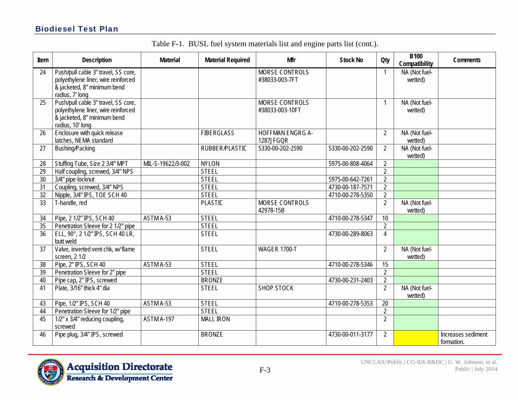
Biodiesel Test Plan
F-3
UNCLAS//Public | CG-926 R&DC | G. W. Johnson, et al. Public | July 2014
Table F-1. BUSL fuel system materials list and engine parts list (cont.).
Item Description Material Material Required Mfr Stock No Qty B100 Compatibility Comments
24 Push/pull cable 3” travel, SS core, polyethylene liner, wire reinforced & jacketed, 8” minimum bend radius, 7' long
MORSE CONTROLS #38033-003-7FT
1 NA (Not fuel-wetted)
25 Push/pull cable 3” travel, SS core, polyethylene liner, wire reinforced & jacketed, 8” minimum bend radius, 10' long
MORSE CONTROLS #38033-003-10FT
1 NA (Not fuel-wetted)
26 Enclosure with quick release latches, NEMA standard
FIBERGLASS HOFFMAN ENGRG A-1287JFGQR
2 NA (Not fuel-wetted)
27 Bushing/Packing RUBBER/PLASTIC 5330-00-202-2590 5330-00-202-2590 2 NA (Not fuel-wetted)
28 Stuffing Tube, Size 2 3/4” MPT MIL-S-19622/3-002 NYLON 5975-00-808-4064 2 29 Half coupling, screwed, 3/4” NPS STEEL 2 30 3/4” pipe locknut STEEL 5975-00-642-7261 2 31 Coupling, screwed, 3/4” NPS STEEL 4730-00-187-7571 2 32 Nipple, 3/4” IPS, TOE SCH 40 STEEL 4710-00-278-5350 2 33 T-handle, red PLASTIC MORSE CONTROLS
42978-15B 2 NA (Not fuel-
wetted)
34 Pipe, 2 1/2” IPS, SCH 40 ASTM A-53 STEEL 4710-00-278-5347 10 35 Penetration Sleeve for 2 1/2” pipe STEEL 2 36 ELL, 90°, 2 1/2” IPS, SCH 40 LR,
butt weld STEEL 4730-00-289-8063 4
37 Valve, inverted vent chk, w/ flame screen, 2 1/2
STEEL WAGER 1700-T 2 NA (Not fuel-wetted)
38 Pipe, 2” IPS, SCH 40 ASTM A-53 STEEL 4710-00-278-5346 15 39 Penetration Sleeve for 2” pipe STEEL 2 40 Pipe cap, 2” IPS, screwed BRONZE 4730-00-231-2403 2 41 Plate, 3/16” thick 4” dia STEEL SHOP STOCK 2 NA (Not fuel-
wetted)
43 Pipe, 1/2” IPS, SCH 40 ASTM A-53 STEEL 4710-00-278-5353 20 44 Penetration Sleeve for 1/2” pipe STEEL 2 45 1/2” x 3/4” reducing coupling,
screwed ASTM A-197 MALL IRON 2
46 Pipe plug, 3/4” IPS, screwed BRONZE 4730-00-011-3177 2 Increases sediment formation.

Biodiesel Test Plan
F-4
UNCLAS//Public | CG-926 R&DC | G. W. Johnson, et al. Public | July 2014
Table F-1. BUSL fuel system materials list and engine parts list (cont.).
Item Description Material Material Required Mfr Stock No Qty B100 Compatibility Comments
47 Nipple, 3/4” IPS, short, TBE, STD WT
STEEL 4730-00-196-2058 2
48 Union, 3/4” NPT, threaded ASTM A-197 MALL IRON 4730-00-189-2617 1 49 FO hand stripping pump BLACKMER 2910-01-134-6590 1 Blackmer indicates it
is Ok with Biodiesel. 50 ELL, 90°, STREET 3/4” NPT ASTM A-197 MALL IRON 1 51 Hose , similar to item 3 AEROQUIP FC 234-12 4720-01-280-2307 14 52 Hose end fitting for -12 hose,
3/4/MPT STEEL AEROQUIP 412-12-12S 4730-00-374-6947 2 NA Part of FLOCS
53 ELL, 45°, 1/2” IPS socket weld STEEL 4730-01-014-2671 2 Part of Tank Stripping System
54 1/4 - 20 bolt, 1/2” long, hex head STEEL 5305-00-068-0500 8 NA (Not fuel-wetted)
55 12 gage sheet metal, 48” x 96” STEEL 1 NA (Not fuel-wetted)
56 Main eng FO filter separator with 4 Way Valve
RACOR #75/500MAX 2 Entire assy will be replaced by Racor777R heated filter assy. B100 filter element will be Snap Green Technology filters, part number 6732
57 GENSET engine FO filter separator with 4-way valve
RACOR #75/500MAX 1 Entire assy will be replaced by Racor777R heated filter assy. B100 filter element will be Snap Green Technology filters, part number 6732
58 Flocs pump AEROQUIP FLOC #15/PT#FF9315-01
1 NA Pump for changing LO
59 Flat Bar 1” wide x 3/16” Thick Mil-S-20166 STEEL NA (Not fuel-wetted)
60 Wire Rope, 7 x 7 Strand, 1/16' Diameter
Alloy 304 STN STL NA (Not fuel-wetted)

Biodiesel Test Plan
F-5
UNCLAS//Public | CG-926 R&DC | G. W. Johnson, et al. Public | July 2014
Table F-1. BUSL fuel system materials list and engine parts list (cont.).
Item Description Material Material Required Mfr Stock No Qty B100 Compatibility Comments
61 Compression Sleeve for 1/16” wire rope, swaging sleeve
STN STL 4030-01-088-2952 20 NA (Not fuel-wetted)
62 Machine Screw, 6-32 x 3/8 long, pan head
Alloy 304 STN STL 5305-00-054-6652 10 NA (Not fuel-wetted)
63 Pipe, 3/4”, SCH 40 ASTM A-53 STEEL 4710-00-278-5350 2 64 Bushing/Packing Rubber/Plastic 5330-00-202-
2589 2 Not found on
drawings. Could be similar to 27.
65 Screw, Banjo Connector-Injection pump supply
Zink-plated steel Cummins will provide B100 compatible replacement
ID’d by Cummins 3918002 2 1/propulsion engine
66 Washer, sealing-Injection pump supply
Rubber coated steel Cummins will provide B100 compatible replacement
ID’d by Cummins 3918190 2 1/propulsion engine
67 Washer, sealing-Fuel plumbing Rubber coated steel Cummins will provide B100 compatible replacement
ID’d by Cummins 3918188 3
1/propulsion engine, 1/generator engine-Total 3
68 Washer, sealing-Fuel plumbing Rubber coated steel Cummins will provide B100 compatible replacement
ID’d by Cummins 3918192 5 2/propulsion engine, 1/generator engine-Total 5
69 Washer, sealing-Fuel inlet tube Rubber coated steel Cummins will provide B100 compatible replacement
ID’d by Cummins 3918192 3 1/propulsion engine, 1 per/generator engine-Total 3

Biodiesel Test Plan
F-6
UNCLAS//Public | CG-926 R&DC | G. W. Johnson, et al. Public | July 2014
Table F-1. BUSL fuel system materials list and engine parts list (cont.).
Item Description Material Material Required Mfr Stock No Qty B100 Compatibility Comments
70 Hose, flexible material ¼” rubber tube, single wire reinforcement, black polyester braided cover
Cummins will provide B100 compatible replacement
ID’d by Cummins 3923081 1 1/generator engine
Notes Material list from DWG 49A BUSL
541-001, Rev A, 4 Sheets
Compatibility Red = Not Recommended Yellow = May be some effect Green = Satisfactory Based on Appendix E of Biodiesel Handling and Use Guide (NERL, 2009)

Biodiesel Test Plan
G-1
UNCLAS//Public | CG-926 R&DC | G. W. Johnson, et al.Public | July 2014
APPENDIX G FIELD TESTING DATA SHEETS
Test 1: Idle test (30 min) Idle Testing ‐‐ Test 1‐‐ 30 minute idle test Date: Task Time
Completed Notes
1 Pretest check List:
a Boat checks performed by the crew
b Normal engine checks IAW LIS SOP performed by the crew
c Ensure test data sheet is filled out and ready for entries including date and time
d Start all data recorders
e Record any non‐data information; i.e., weather observations, crew personnel list, fuel level and miscellaneous information
f Green‐Amber‐Red (GAR) by Coxswain
g Ensure observers are in place is part of test plan
h Observe all safety requirements inside engine rooms; i.e., double hearing protection, eye protection, etc.
i Start engines
2 Test Procedure DOES NOT reflect emissions testing! TBD by RDC
a Idle until engines are at operating temp
b Let engines idle for 30 minutes
c Note any abnormalities*
3 Post‐test checklist a Shutdown engines
b Stop data recording
c Secure test observers if they were used
d Copy test data onto laptop
e Confirm test data has been successfully copied
f Backup test data onto external hard drive
g Secure power to test equipment
h Secure all of equipment for the night
*Any observation that is deemed abnormal by the observer should be reported to the test personnel and senior engineer immediately

Biodiesel Test Plan
G-2
UNCLAS//Public | CG-926 R&DC | G. W. Johnson, et al.Public | July 2014
Test 2: Idle test (4 hr) Idle Testing ‐‐ Test 2‐‐ Four hour idle test Date: Task Time
Completed Notes
1 Pretest check List:
a Boat checks performed by the crew
b Normal engine checks IAW LIS SOP performed by the crew
c Ensure test data sheet is filled out and ready for entries including date and time
d Start all data recorders
e Record any non‐data information; i.e., weather observations, crew personnel list, fuel level and miscellaneous information
f Green‐Amber‐Red (GAR) by Coxswain
g Ensure observers are in place is part of test plan
h Observe all safety requirements inside engine rooms; i.e., double hearing protection, eye protection, etc.
i Start engines
2 Test Procedure DOES NOT reflect emissions testing! TBD by RDC
a Idle until engines are at operating temp
b Let engines idle for 4 hours
c Note any abnormalities*
3 Post‐test checklist a Shutdown engines
b Stop data recording
c Secure test observers if they were used
d Copy test data onto laptop
e Confirm test data has been successfully copied
f Backup test data onto external hard drive
g Secure power to test equipment
h Secure all of equipment for the night
*Any observation that is deemed abnormal by the observer should be reported to the test personnel and senior engineer immediately

Biodiesel Test Plan
G-3
UNCLAS//Public | CG-926 R&DC | G. W. Johnson, et al.Public | July 2014
Test 3: Slow Speed Cruising-No Maneuvers (2 hrs) Slow Speed Cruising‐No Maneuvers Date: Task Time
Completed Notes
1 Pretest check List:
a Boat checks performed by the crew
b Normal engine checks IAW LIS SOP performed by the crew
c Ensure test data sheet is filled out and ready for entries including date and time
d Start all data recorders
e Record any non‐data information; i.e., weather observations, crew personnel list, fuel level and miscellaneous information
f Green‐Amber‐Red (GAR) by Coxswain
g Ensure observers are in place is part of test plan
h Observe all safety requirements inside engine rooms; i.e., double hearing protection, eye protection, etc.
i Start engines
2 Test Procedure a Idle until engines are at operating temp
b Get underway, mill about smartly for 1 hour Slow speed, course and direction coxswain's discretion
c Tie up
3 Post‐test checklist a Shutdown engines
b Stop data recording
c Secure test observers if they were used
d Copy test data onto laptop
e Confirm test data has been successfully copied
f Backup test data onto external hard drive
g Secure power to test equipment
h Secure all of equipment for the night
*Any observation that is deemed abnormal by the observer should be reported to the test personnel and senior engineer immediately.

Biodiesel Test Plan
G-4
UNCLAS//Public | CG-926 R&DC | G. W. Johnson, et al.Public | July 2014
Test 4: Slow Speed-Low Impact Maneuvers (1 hr) Slow Speed‐Low Impact Maneuvers Date: Task Time
Completed Notes
1 Pretest check List:
a Boat checks performed by the crew
b Normal engine checks IAW LIS SOP performed by the crew
c Ensure test data sheet is filled out and ready for entries including date and time
d Start all data recorders
e Record any non‐data information; i.e., weather observations, crew personnel list, fuel level and miscellaneous information
f Green‐Amber‐Red (GAR) by Coxswain
g Ensure observers are in place is part of test plan
h Observe all safety requirements inside engine rooms; i.e., double hearing protection, eye protection, etc.
i Start engines
2 Test Procedure a Idle until engines are at operating temp
b Get underway, slow S turns; approximately 10 rolls
Slow speed, course and direction Coxswain’s discretion
c Tie up
3 Post‐test checklist a Shutdown engines
b Stop data recording
c Secure test observers if they were used
d Copy test data onto laptop
e Confirm test data has been successfully copied
f Backup test data onto external hard drive
g Secure power to test equipment
h Secure all of equipment for the night
*Any observation that is deemed abnormal by the observer should be reported to the test personnel and senior engineer immediately

Biodiesel Test Plan
G-5
UNCLAS//Public | CG-926 R&DC | G. W. Johnson, et al.Public | July 2014
Test 5: Cruising Speed-No Maneuvers (2 hrs) Cruising Speed‐No Maneuvers Date: (defined by the BUSL handbook as 7 knots) Task Time
Completed Notes
1 Pretest check List:
a Boat checks performed by the crew
b Normal engine checks IAW LIS SOP performed by the crew
c Ensure test data sheet is filled out and ready for entries including date and time
d Start all data recorders
e Record any non‐data information; i.e., weather observations, crew personnel list, fuel level and miscellaneous information
f Green‐Amber‐Red (GAR) by Coxswain
g Ensure observers are in place is part of test plan
h Observe all safety requirements inside engine rooms; i.e., double hearing protection, eye protection, etc.
i Start engines
2 Test Procedure a Idle until engines are at operating temp
b Get underway, mill about smartly for 2 hours at ~ 7 knots
Cruising speed, course and direction Coxswain’s discretion
c Tie up
3 Post‐test checklist a Shutdown engines
b Stop data recording
c Secure test observers if they were used
d Copy test data onto laptop
e Confirm test data has been successfully copied
f Backup test data onto external hard drive
g Secure power to test equipment
h Secure all of equipment for the night
*Any observation that is deemed abnormal by the observer should be reported to the test personnel and senior engineer immediately

Biodiesel Test Plan
G-6
UNCLAS//Public | CG-926 R&DC | G. W. Johnson, et al.Public | July 2014
Test 6: Cruising Speed-Low Impact Maneuvers (1 hr) Cruising Speed‐Low Impact Maneuvers Date: (defined by the BUSL handbook as 7 knots) Task Time
Completed Notes
1 Pretest check List:
a Boat checks performed by the crew
b Normal engine checks IAW LIS SOP performed by the crew
c Ensure test data sheet is filled out and ready for entries including date and time
d Start all data recorders
e Record any non‐data information; i.e., weather observations, crew personnel list, fuel level and miscellaneous information
f Green‐Amber‐Red (GAR) by Coxswain
g Ensure observers are in place is part of test plan
h Observe all safety requirements inside engine rooms; i.e., double hearing protection, eye protection, etc.
i Start engines
2 Test Procedure a Idle until engines are at operating temp
b Get underway, S turns for 2 hours, 6‐8° rolls hours at ~ 7 knots
Cruising speed, course and direction Coxswain’s discretion. This should be a round at 9 knots
c Tie up
3 Post‐test checklist a Shutdown engines
b Stop data recording
c Secure test observers if they were used
d Copy test data onto laptop
e Confirm test data has been successfully copied
f Backup test data onto external hard drive
g Secure power to test equipment
h Secure all of equipment for the night
*Any observation that is deemed abnormal by the observer should be reported to the test personnel and senior engineer immediately

Biodiesel Test Plan
G-7
UNCLAS//Public | CG-926 R&DC | G. W. Johnson, et al.Public | July 2014
Test 7: Cruising Speed Medium Impact Maneuvers (1 hr) Cruising Speed Medium Impact Maneuvers Date: (defined by the BUSL handbook as 7 knots) Task Time
Completed Notes
1 Pretest check List:
a Boat checks performed by the crew
b Normal engine checks IAW LIS SOP performed by the crew
c Ensure test data sheet is filled out and ready for entries including date and time
d Start all data recorders
e Record any non‐data information; i.e., weather observations, crew personnel list, fuel level and miscellaneous information
f Green‐Amber‐Red (GAR) by Coxswain
g Ensure observers are in place is part of test plan
h Observe all safety requirements inside engine rooms; i.e., double hearing protection, eye protection, etc.
i Start engines
2 Test Procedure a Idle until engines are at operating temp
b Get underway, S turns for 2 hours, 8‐12° rolls hours at ~ 7 knots
Cruising speed, course and direction Coxswain’s discretion. This should be a round at 9 knots
c Tie up
3 Post‐test checklist a Shutdown engines
b Stop data recording
c Secure test observers if they were used
d Copy test data onto laptop
e Confirm test data has been successfully copied
f Backup test data onto external hard drive
g Secure power to test equipment
h Secure all of equipment for the night
*Any observation that is deemed abnormal by the observer should be reported to the test personnel and senior engineer immediately

Biodiesel Test Plan
G-8
UNCLAS//Public | CG-926 R&DC | G. W. Johnson, et al.Public | July 2014
Test 8: Full Power Trial (2 hrs) Full power Trial Date: Task Time
Completed Notes
1 Pretest check List:
a Boat checks performed by the crew
b Normal engine checks IAW LIS SOP performed by the crew
c Ensure test data sheet is filled out and ready for entries including date and time
d Start all data recorders
e Record any non‐data information; i.e., weather observations, crew personnel list, fuel level and miscellaneous information
f Green‐Amber‐Red (GAR) by Coxswain
g Ensure observers are in place is part of test plan
Observers not needed for this test
h Observe all safety requirements inside engine rooms; i.e., double hearing protection, eye protection, etc.
i Start engines
2 Test Procedure a Idle until engines are at operating temp
b IAW BUSL handbook Procedure on next 2 pages
c Tie up
3 Post‐test checklist a Shutdown engines
b Stop data recording
c Secure test observers if they were used
d Copy test data onto laptop
e Confirm test data has been successfully copied
f Backup test data onto external hard drive
g Secure power to test equipment
h Secure all of equipment for the night
*Any observation that is deemed abnormal by the observer should be reported to the test personnel and senior engineer immediately
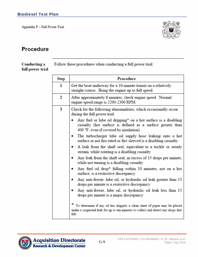
Biodiesel Test Plan
G-9
UNCLAS//Public | CG-926 R&DC | G. W. Johnson, et al.Public | July 2014
Appendix F - Full Power Trial
Procedure
Conducting a full power h ·ial
Follow these procedures when conducting a full power trial:
Step Pro~edw·e
I Get the boat unden"aY for a 10-mi.nute transit on a relatively straight cm.lfS·e. Bring the ·engine up to fuU speed.
2 After approximately 8 minutes. check engine speed. Nonnal engine speed range is 2200-2300 RPM.
3 Check for the foUm.ving abnonnalities. which occasionally occur dming the fuU power trial:
• Any fuel or lube oil dripping* on a hot surface is a disabling casualty (hot surface ts defined as a surface greater than 400 °F, even if covered by insulation)
• The ttlfbocharger lube oil. supply hose leaking onto a hot surface or not fire rated or fire sleeved is a disabling casualty
• A leak from the shaft seal, equivalent to a trickle or st.eady st:reru.n, \\ihde rotating is a disabling casualty
• Any leak from the sha£t seat in excess of 15 drops per minut.e. \:~.rhile not turning is a disabling casualty
• Any fuel oil di op* falling within 1 0 minutes. not on a hot surface, is a restrictive discrepancy
• Any anti-freeze, lube oil, or hydraulic oil leak greater than 15 drops per minut.e is a restrictiv·e discrepancy
• Any anti-freeze, lube oil. or hydraulic oil leak less than 15 drops per minut.e is a major discrepancy
* To detenlline if any oil has dripped., a clean sheet of paper may be plac:e:d unde:· a suspected leak for up to ten minutes to collect and deted any drops that falJ.
Acquisition Directorate Research & Development Center

Biodiesel Test Plan
G-10
UNCLAS//Public | CG-926 R&DC | G. W. Johnson, et al.Public | July 2014
Cat.egodes
Oil Pr,essure (PSI)
Water Temperature (of )
Reduction Ge.ar Pressure (PSI)
Engine Speed (RPM)
Appendix F- FuJl Power Trial
Step P1·oc·edm·e-
.4 Check all gauge-s on dl.e console and record the readings_ Refer to
the foUowing chart for allowable ranges and results:
I Disabling I Restrictive I Majior I Normal I Major I Restrictiv·e I Disabling
<30 30~70
<140
<280
155-18!5 >205
300~320 >35()
<2100 2200-2300 >2350
5 Return to tl1e- mooring. Secure both engines and che-ck all fuel fit6ngs.
• lw.y fuel oil leak .is a restrictive discr,e-pancy
Acquisition Directorate Research & Development Center

Biodiesel Test Plan
H-1
UNCLAS//Public | CG-926 R&DC | G. W. Johnson, et al.Public | July 2014
APPENDIX H SAMPLE OPERATIONAL TESTING DATA SHEET
Table H-1. Sample operational testing data sheet.
Date Fuel #
Gal Event
Description of Event-Notes-Observations
Name Signature
Examples
11-May-12 X 326 Sample collected MK1 Joe Blow
11-May-12 X Sample sent to lab; tracking number XL12929447563
MK1 Joe Blow
18-May-12 X Filters changed; old filters saved in storage
FN Jim Bean
23-May-12 X 247 Fuel truck broke, had to use buckets to fill tank
MK3 Ben Hur
30-May-12 X Engines were over heating, inspection of the coolant hoses showed a mouse inside blocking the coolant, it was determined the mouse crawled in during B100 fueling, anti-mouse filters installed on fuel hose
MK2 Bean Counter
3-Jun-12 X 325 Sample collected MK1 Joe Blow
3-Jun-12 X Sample sent to lab; tracking number XL1288540275
MK1 Joe Blow
10-Jun-12 X Fuel line heater leaking, test team leader contacted. Test team tech arrived, inspected heater, determined that the hose was loose, FN Wrench tightened clamp
FN Rusty Wrench

Biodiesel Test Plan
H-2
UNCLAS//Public | CG-926 R&DC | G. W. Johnson, et al.Public | July 2014
(This page intentionally left blank.)