bill palmteer book chapter
TRANSCRIPT

Introduction
Additive manufacturing (AM) also known as 3D printing has been around for
over 30 years and is now taking center stage in the medical manufacturing field.
Initially computing power hindered the technology but over the years various
3D printing technologies have emerged providing the ability to make complex
moving/interlocking products out of a wide range of material(s). These new
AM processes and materials, when used in the correct application are slowly
displacing a percentage of the more traditional subtractive processes like CNC,
machining and casting. Wide ranging applications for AM technologies exist in
the medical industry for customer specific surgical tools, soft prosthetics and
structural replacements for bone/joints each requiring unique material
properties. The first 510K was issued by the FDA in 2012 for an implantable
product and has cleared the way for this technology but the newcomers will still
need to validate the new processes/materials will meet biocompatibility,
sterilization, safety and efficacy standards.
Prosthetics
Implants
Custom Tools
Bill Palmteer 5/4/15

The Emergence of 3D Printing in Biomedical Applications 2
3D Printing Methods and Materials
Since the inception of 3D printing various forms of additive manufacturing have arisen here we
will only cover FDM/FFF (Fusion Deposition Modeling, Fusion Filament Fabrication), PLS
(Polymer Laser Sinter), DMS (Direct Metal Sinter) and lastly CLIP (Continuous Liquid Interface
Production Technology). Reviewing these 3 technologies will provide an adequate overview of
the potential medical products that can be manufactured, associated material and capital costs, and
time to market.
Imaging Requirements (Hardware/Software)
In order to make a 3D solid object using additive manufacturing processes you first need to acquire
a scan of the object you want to replicate or create a 3D computer model. The computer model
can be created using one of the many 3D rendering software’s such as Solid works, Google Sketch,
Pro-E or Rhinoceros. If the actual object
already exists that you want to replicate then it
can be scanned into the computer by using
various scanners on the market. For medical
applications, CT, MRI and even ultrasound
scans are capable of producing the data that is
needed. For dental applications one such
scanner is called iTero and is shown in Fig 1.
This is the latest technology being used in the
dental office replacing the need for
castings/impressions which are time
consuming and composed of distasteful
materials. Like most scanners, the iTero scanner digitally captures the structure of the teeth and
gums by projecting 100,000 points of laser light and capturing the reflective energy on a photo
sensor transmitting the data back to the computer. The data can then be used to 3D print accurate
crowns, veneers, Invisalign and other dental appliances (Itero, 2014).
At this point, in some customization to the file might be needed. In some cases to maximize
throughput rather than printing one part at a time the user may wish to make multiple copies of an
object or several different objects at a time. The space available for printing is based on the 3D
printer and its print base. Also, one may choose to add a spruce or support structures that can be
removed after the printing.
Fig 1: iTero Dental Scanner

The Emergence of 3D Printing in Biomedical Applications 3
Once a 3D computer model is completed the file needs to be manipulated into the industry standard
exchange format for additive
manufacturing is the STL
(STereo Lithography or
Standard Triangulation
Language) file. Basically, it is a
file that replaces the original
surface of solid, surface or
scanned model with a mesh of
triangulated surface segments.
Almost all of today's CAD
systems are capable of
producing a .STL file. Within
the software you can control the
variables that control the mesh
size. If you create a finer mesh
you will a larger .STL file but
you will end up with a better 3D
print. However, increasing the
resolution excessively may not
improve the quality of the
produced part and could cause
delays in processing because of
the larger size.
The next step is to convert the
*.STL file to G Code which the
3D printer understands. The G
Code establishes the “slicing” or
sectioning CAD design into
layers. The preprocessing
software calculates section and
slices the part design into many
layers, ranging from 0.005
inches (0.127 mm) to 0.013
inches (0.3302 mm) in height.
Using the sectioning data, the
software then generates “tool
paths” or building instructions, which will drive the type of 3D printer. We will touch briefly
again on additional capabilities of software under PLS/DLS (Hiemenz, 2014)
Fig. 2: Hardware/software flow chart, created by author

The Emergence of 3D Printing in Biomedical Applications 4
Fused Deposition Modeling
Depending on the type of equipment used most thermoplastic resins can be printed using FDM.
The most common thermoplastics are ABS (Acrylonitrile Butadiene) which is used to make Lego’s
and PLA (Polylactic Acid) which can be plant based and recyclable. Equipment manufacturers
like Makerbot replicator 2, shown in Fig. 3.1 specify the thermoplastic filament be supplied on a
reel with a specified filament diameter between 1.75-3mm thick(Hiemenz, 2014). One reel holds
about 2.2 lbs. of material enough to produce approximately 400 chess pieces. The filament (Fig.
3.1) is loaded into the equipment and then a gear pulls the filament to the print head and then
through the extruder nozzle (Fig. 3.2). Depending on the filament material the nozzle temperature
is between 215-230 oC. The nozzle orifice comes in diameters between .4mm-1mm. A smaller
orifice size equates to finer detail but slower build speeds while the larger sizes will produce faster
builds and thicker wall widths. In some equipment there might be two print heads so that you can
print two different colors and materials at the same time. The nozzle then extrudes the heated
plastic onto the printing surface commonly referred to the print bed (Fig. 3.3). For ABS and some
other plastics the print bed needs to be heated to optimize cooling rate and reduce shrinkage. The
print bed may also contain support structures that might be needed to support the 3d object. In
some cases this is also printed and is shown in Fig. 3.5 (Makerbot, 2014)
Fig 3: Makerbot & Stratasys FDM Process (graphics modified by author)

The Emergence of 3D Printing in Biomedical Applications 5
As sequential layers (Fig. 3.4-5) are added the print bed moves down. The secret to FDM’s
technology is the movement of the print bed, print head, and material flow rate are all constantly
changing in concert. The print head is suspended on the gantry system which is composed of two
metal bars that run left to right and two
more metal bars connected front to
back. This allows the print head to
move in four directions altogether.
The print head accelerates and
decelerates as it travels across the print
bed and as the head speed changes, the
drive wheels adjust the material flow
rate. The result produces each layer
composed of a flat ribbon of material
that measures from 0.008 inch to 0.038
inch wide (0.20 mm to 0.97 mm) and
as fine as 0.005 inch high (0.13 mm).
On the highest-performance FDM
machines, part accuracy can reach as high as 0.003 inch (0.08 mm), which rivals injection molding.
However, as you can see in Figure 4 a rather rough, stepped surface is produced (He, 2014))
While different printers have different build volumes the build volume for the Makerbot is 28.5 x
15.3 x 15.5cm. While the enclosure limits the overall print area it also has some benefits. First, it
is safety mechanism preventing probing hands from getting near the moving gantry and hot
extruder. Secondly, melting plastic can lead to unwanted and possibly toxic odors so it helps to
retain the fumes so they can be properly vented to an outside environment. Thirdly, it limits any
drafts that could enter the build area depositing any airborne particle in the thermoplastic.
PLS (Polymer Laser Sinter) and DLS (Direct Laser Sinter)
PLS and DLS both use the same method to manufacture
AM components. One major difference between laser
sinter and FDM is the use of a laser and the raw materials
come in powder form. In order to fuse or sinter high
performance polymers and metals like HP3 PEK, PEEK,
PEKK, and Titanium you need a high temperature laser.
Shown in Fig. 5 is one machine used to perform AM at
high temperatures, EOSINT P800 made by EOS.
The basic process begins with loading the material of choice
into the powder bed. In order to produce a final product
with uniform high density, consistent surface quality and Fig. 5: EOSINT 800 P
Fig 4: Rough surface created by FDM (He, 2014)

The Emergence of 3D Printing in Biomedical Applications 6
accuracy the particle size distribution has to
be tightly controlled. Fig. 6 depicts the
optimum particle distribution size roughly
centered on 63 micron (Berretta, 2014).
Without adhering to the particle distribution
curve various negative side effects like poor
flow, agglomeration and undesired sintering
can occur. Incorrect particle size can cause
difficulty removing the unsintered powder
from the finished product and fogging of the
optical elements inside the system. As
depicted in Fig 7 the powder is then spread
across evenly across the build platform by a
leveling roller. A 50 W CO2 laser beam is
then focused through optical lenses and
redirected downward to the appropriate coordinates by an x-y scanning mirror. As the laser hits
the powder it fuses it together. As the process is repeated the powder bed is raised and the build
platform is lowered to allow
the roller to push more
powder over the previously
sintered layer. While the
layer thickness capability is
dependent on the powder
material and equipment type
being used typical thickness
that can be achieved is .12mm
(.005 in). Typical part
accuracy can reach +/- 0.25
mm but can be improved with
post processing. Due to the
high sintering temperatures
required (< 385 oC) and to
limit the material from
oxidizing the entire process
takes place in a sealed chamber filled with an inert gas such as
Nitrogen or Argon gas. Unlike FDM no support structures are
required and parts can be built on top of each other as the
unsintered material will help support the sintered structures
during processing. The effective build volume of the EOSINT
P800 is 700mm x 380mm x 560mm (27.6 x 15 x 22.05 in).
Once the product is completed they are removed from the build
chamber and now they need to be cleaned. The process of
removing the unsintered powder can be simple or highly
complex and is based on the product structure and end use
application. Shown in Fig 8 is the most basic process of
blowing a compressed gas of nitrogen or air on the finished
Fig. 6: Peek particle size distribution
Fig. 7: EOSINT 800 P Build Area (graphic modified by author)
Fig 8: Compressed Air Clean
The Emergence of 3D Printing in Biomedical Applications 7
product. A more complex process that might be used for medical products containing porous
structures and/or hollow cavities can consist of multi-step blowing, rinse and ultrasonic cleaning
process (EOS Alphaform, 2015).
One of the drawbacks of laser sintering systems is the ability to switch materials quickly. While
the costly raw powder can be reused after sieving the material has to be removed entirely before
introducing a different raw material.
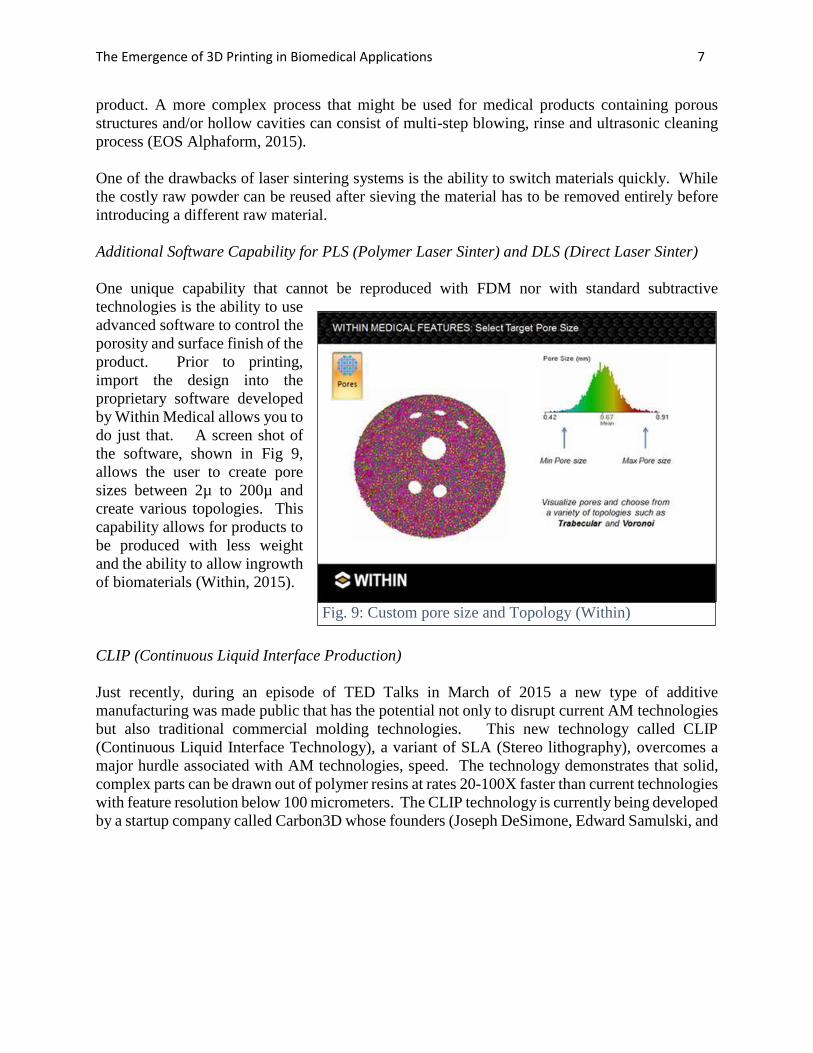
Additional Software Capability for PLS (Polymer Laser Sinter) and DLS (Direct Laser Sinter)
One unique capability that cannot be reproduced with FDM nor with standard subtractive
technologies is the ability to use
advanced software to control the
porosity and surface finish of the
product. Prior to printing,
import the design into the
proprietary software developed
by Within Medical allows you to
do just that. A screen shot of
the software, shown in Fig 9,
allows the user to create pore
sizes between 2µ to 200µ and
create various topologies. This
capability allows for products to
be produced with less weight
and the ability to allow ingrowth
of biomaterials (Within, 2015).
CLIP (Continuous Liquid Interface Production)
Just recently, during an episode of TED Talks in March of 2015 a new type of additive
manufacturing was made public that has the potential not only to disrupt current AM technologies
but also traditional commercial molding technologies. This new technology called CLIP
(Continuous Liquid Interface Technology), a variant of SLA (Stereo lithography), overcomes a
major hurdle associated with AM technologies, speed. The technology demonstrates that solid,
complex parts can be drawn out of polymer resins at rates 20-100X faster than current technologies
with feature resolution below 100 micrometers. The CLIP technology is currently being developed
by a startup company called Carbon3D whose founders (Joseph DeSimone, Edward Samulski, and
Fig. 9: Custom pore size and Topology (Within)

The Emergence of 3D Printing in Biomedical Applications 8
Ermoshkialled) tailored the innovative process by which it works. Shown in Fig. 10 is the simple
underlying architecture for the basis of the CLIP technique. The objects are built above a vat of
room temperature liquid UV curable resin (DeSimone, 2015).
The basic principle to the technology is maintaining a “Dead Zone”, a thin uncured liquid layer
between the oxygen permeable window and the cured part surface. UV light triggers photo
polymerization and oxygen
inhibits it. By carefully balancing
the interaction of light and
oxygen, CLIP continuously
grows objects from a pool of
resin. The object being built is
anchored to a platform which is
slowly raised out of the resin.
Beneath the build platform, are
adjustable optics and a high
power UV light source
continually altering its image by a
Digital Light Processing (DLP)
imaging unit. DLP imaging has
been a mainstream technology in
TV sets for many years now. The image is then projected through a thin membrane with the same
properties as contact lenses. In this case the material is amorphous fluoropolymer, Teflon AF 2400
which has excellent oxygen permeability, UV transparent and chemically inert. The object is
constructed as light from the projector hardens the layers of resin and as the platform rises upwards
produces suction
forces that constantly
renew reactive liquid
resin. Compared to
other additive
technologies the
projector draws entire
layers at once (hence
the speed). Figure 11
shows a comparison
at 130X between
CLIP technology
versus other 3D
printed process. Clearly, the latter does not exhibit the same “stepped” surface nor does it suffer
a deficit of mechanical properties in-between cured layers like that of FDM/PLS/DLS technologies
(Tumbleston, 2015).
Fig. 10: CLIP Setup
Fig. 11: 130x Electron microscope surface finish image.
100 Micron
The Emergence of 3D Printing in Biomedical Applications 9
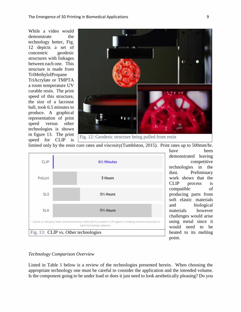
While a video would
demonstrate the
technology better, Fig.
12 depicts a set of
concentric geodesic
structures with linkages
between each one. This
structure is made from
TriMethylolPropane
TriAcrylate or TMPTA
a room temperature UV
curable resin. The print
speed of this structure,
the size of a lacrosse
ball, took 6.5 minutes to
produce. A graphical
representation of print
speed versus other
technologies is shown
in figure 13. The print
speed for CLIP is
limited only by the resin cure rates and viscosity(Tumblston, 2015). Print rates up to 500mm/hr.
have been
demonstrated leaving
competitive
technologies in the
dust. Preliminary
work shows that the
CLIP process is
compatible of
producing parts from
soft elastic materials
and biological
materials however
challenges would arise
using metal since it
would need to be
heated to its melting
point.
Technology Comparison Overview
Listed in Table 1 below is a review of the technologies presented herein. When choosing the
appropriate technology one must be careful to consider the application and the intended volume.
Is the component going to be under load or does it just need to look aesthetically pleasing? Do you
Fig. 13: CLIP vs. Other technologies
Fig. 12: Geodesic structure being pulled from resin

The Emergence of 3D Printing in Biomedical Applications 10
need to manufacture just one or thousands? Does the material need to be biocompatible or hold up
to sterilization requirements? These are just some of the questions one should ask themselves.
Material Properties
Table 2 indicates some of the important properties of a select few of the readily available materials
that can be used in additive printing. Also, while not every variant is biocompatible within each
class each major category does have a version that is biocompatible. PLA and ABS are the most
economically priced materials while Titanium is the upper echelon of materials. Compared to
ABS, PLA demonstrates much less part warping and curling and, for this reason, can be
successfully printed without a heated build plate. Details such as sharp corners and edges print
well with PLA and generally retain a glossier look and feel.
While PLA is the easiest to print it does not have retain the mechanical properties to be used for
structural or mechanically functionality but is quite suitable for molds. ABS, PEEK and of course
Titanium can all be used in demanding mechanical and high temperature applications. Two unique
properties of ABS is its solubility in Acetone which allows one to readily smooth the surface or
weld components together, also ABS does not have a true melting point since it is amorphous.
FDM
• Capital: $1-50K
• Material: $$
• Speed: Medium
• Strength: Med.
• Finish: Rough
• Resolution: Low
• May require support structures
• Poor Z-axis strength
• Easily create complex shapes
PLS/DLS
• Capital: $.2-1.5M
• Material: $$$
• Speed: Slow
• Strength: High
• Finish: Rough
• Resolution: High
• Can customize porosity
• Create moving & interlocked geometries
• High temp. applications above 180 OC
CLIP
• Capital: <$5000
• Material: $
• Speed: Fast
• Strength: High
• Finish: Smooth
• Resolution: High
• New Technology risk
Molding &
Machining
• Capital: $1.5M
• Material: $
• Speed: Fast
• Strength: High
• Finish: Smooth
• Resolution: High
• Requires cutting oils or mold release agents
• Requires mold draft angles
Table 1: AM Technology Review (created by author)

The Emergence of 3D Printing in Biomedical Applications 11
MATERIALS
PROPERTIES PLA ABS PEEK Titanium (Ti6AlV4)
Glass Transition Temp. (oC) 60-65 105 157 n/a
Melt Temp. (oC) 150-160 n/a 372 899
Young's Mod. (GPa) 3.5 1.7-2.8 4.25 110
Tensile Strength (MPa) 50 33-110 90 1150
Hardness 77-81 R 110 85 45.9 C
Biocompatibility Yes Yes Yes Yes
Cost $/kg 48 48 70 250-400
One of the major differences in PLS/DLS vs. traditional injection/compression molding
technologies is the variation in mechanical/dimensional
properties of the part based on part orientation and
location within the build platform. A study
demonstrating these differences was conducted using the
EOSINT 800P and EOS HP3 PEK material (Ghita,
2014). HP3 PEK is a recent formulation developed by
EOS specifically for PLS and has a higher melting point
then traditional PEEK. The study conducted destructive
tensile testing of a 162 industry standard (ISO 527-2-1A)
dog bone shaped test coupons laser sintered at various
locations/directions on the test bed. The shape and
orientation of the dog bone coupons can be seen in Figure
14. X (Ghita, 2014). The resultant Ultimate Tensile
Strength (UTS) based on print direction is shown plotted
against traditional Injection Molding (IM) in Fig. 15 (Ghita, 2014). Furthermore, Fig. 16 (Ghita,
2014) depicts the percent shrinkage map
based on Z-direction of the build samples
that occurred in the build chamber of the
P800. The plot indicates the maximum
shrinkage occurs towards the center of the
chamber where the light colors are with the
least shrinkage occurring around the edges
where the darker colors are. You will
notice that top right of the plot does not
indicate any color as test coupons were not
built in this quadrant. During this
evaluation it is expected the build chamber
to have symmetry in terms of thermal
gradients and that 3 quadrants would be adequately predict the build chamber profile. During
Fig. 15: Tensile strength direction dependent Plot
Fig 14: Test Coupon Distribution
Table 2: Common AM Material Properties (created by author)

The Emergence of 3D Printing in Biomedical Applications 12
cooling, polymer shrinkage
occurs in both injection
molding and additive
manufacturing and can be
countered by predictive
software modeling and
increasing the geometry size
before manufacturing.
Shrinkage can only be
corrected only if it is
predictably consist across the
build platform and lot/batch
processed. The findings of the
paper demonstrate while there
is some improvements to be
made with respect to materials
and methods that overall High Temperature Laser Sintering can rival the expected quality of
traditional manufacturing means (Ghita, 2014).
Slowly, over the past ten years new AM
materials for medical applications are
displacing traditional materials such as
titanium, stainless steel and ceramics in a
variety of components spinal fusion, hip
replacement, craniofacial and dental implants.
Oxford Performance Materials (OPM), a
company based in Oxford, Connecticut has
been working on a new version of a polyketone
for medical applications they are calling PEKK,
or PolyEtherKetoneKetone. OPM states that
“PEKK has a density and stiffness similar to
bone, is lighter than traditional implant
materials such as titanium and stainless steel,
and is chemically inert.” Unlike the aforementioned metals, PEKK is radiolucent, meaning it does
not interfere with diagnostic imaging equipment. According to OPM, other advantages are said to
be a lower coefficient of thermal expansion and superior dimensional stability (Hanson, 2013).
Some of PEKK’s properties are shown in Table 3 (OXPEKK®-IG datasheet, Author 2015).
The importance of utilizing biocompatible materials that contain biomimic constituents like
stiffness and porosity can have an active effect on the attachment, size, migration, proliferation
and function of both endogenous and exogenous cells (Atala, 2014). OPM has successfully shown
biocompatibility testing for 52-weeks per ISO 10993 for OXPEKK®-IG. Perhaps its most
exciting attribute is bone’s affinity to the material. “PEKK as a molecule is unique,” says DeFelice,
President and CEO of OPM (EOS OPM, 2014) “Based on research studies, it is osteoconductive,
Fig. 16: EOSINT 800P shrinkage map of HP3 PEK
Table 3: PEKK Properties (created by author)

The Emergence of 3D Printing in Biomedical Applications 13
meaning bone cells will grow onto it, unlike some the other materials. Without this beneficial
property it is likely that the surrounding tissue will pull away overtime and you will have to rely
on screws to hold it in place. Depicted in Figure 17 is a before and after SEM micrograph taken
3000X resolution of PEKK material deposited with human osteoblast plated at 50,000 cells/cc.
After 10 days of incubation it is apparent that the focal adhesions (FA) are responsible for cell
attachments and are instrumental in translating cell phenotype. The ability of PEKK to reduce
motility demonstrates a value inherent to the material that accentuates osteoblast transduction and
appears to retain cell performance (Ganey, 2011). However, all these new materials will have to
demonstrate their ability to be sterilized and meet the majority of Biocompatibility testing per ISO
10993-1 shown in Table 4. (ISO 10993-1, 2009 ed.)
Fig. 17: PeKK Osteoconductive testing (modified by author)
After Before
Table 4: Biocompatibility Test Matrix (modified by author)

The Emergence of 3D Printing in Biomedical Applications 14
Cranial Implants
Estimates are that 300-500 U.S. patients are in need
of skull bone replacements every month (Felix,
2013). The most common need for cranial implants
are caused by severe trauma to the head from
falling, motorcycle accidents but are also caused by
infection, tumors and rare bone ailments that cause
the skull to grow too thick. The need to remedy the
situation is dire to combat the effects of pressure on
the brain caused by hematoma (Figure 18), which
left untreated decreases blood flow and oxygen to
the brain causing dizziness, nausea, blurred vision,
headache, and left untreated memory loss and
cognitive thinking.
To better comprehend the impact 3D printed implants will have in the 21st century we need to
understand the pitfalls traditional methods of cranial implant manufacturing/installation encounter.
Cranial defects have traditionally been repaired with metal plates or bone cement. During the
mixing and hardening of the bone cement (polymethyl-methacrylate) in the operating theatre it
produces toxic gases. Furthermore, the disadvantage of the conventional method is a perfect fit
Fig. 18: Representation of a hematoma

The Emergence of 3D Printing in Biomedical Applications 15
and curvature can be
difficult to obtain in large
reconstructions, especially
when the defect involves the
craniofacial junction
(Sundseth, 2013). Even with
recent material advances like
Medpor, depicted in Fig. 19
user met needs are still
missing. While Medpor, a
porous polyethylene
material is touted to have
excellent biomaterial
attributes, with a structure
that allows rapid fibro-
vascular growth and
incorporation of the patient’s
own tissue, it does not come
in “one size fits” but rather
20 different sizes! The
author has taken the liberty
to highlight in blue the so
called “Features and
Benefits” of the material, but
with the onset of 3D printing
makes them detriments. The
Medpor literature suggests
that while in the operating
room, with your skull open,
the surgeon will be cutting,
bending and forming the
material to try and
reconstruct the complex
curvature of the skull. Not
only does this process
consume expensive
operating room time but
leaves the patient’s brain
exposed to debris from
cutting Medpor, air borne
pathogens and increased risk
of contamination of the implant due to handling. All of the aforementioned factors can exacerbate
the foreign immune response.
MEDPOR Cranial The MEDPOR Cranial / Neurosurgical portfolio contains more than 20 different implant size and shape options for use in a wide variety of surgical procedures. Many are available with or without embedded titanium mesh for additional cranioplasty solutions. Features & Benefits
Proven material has a long history of use for cranial repair
Interconnected, omni-directional pore structure allows for native tissue in-growth for enhanced biocompatibility
MEDPOR Implants may be contoured with a scalpel, burr, or scissors in the sterile field to fit the individual needs of each patient.
TITAN Implants may be cut with surgical scissors. MEDPOR TITAN™ Implants have titanium mesh
embedded within the porous structure of the MEDPOR biomaterial. This may minimize sharp edges normally associated with cutting titanium mesh implants.
MEDPOR TITAN™ Sheet implants substantially hold their shape when bent, due to the titanium mesh embedded within the porous structure of the MEDPOR biomaterial.
Fig. 19: Courtesy of Stryker (Modified by Author)

The Emergence of 3D Printing in Biomedical Applications 16
Just over 2 years ago, in Feb. of 2013
the FDA approved the first 510(k)
clearance for the use of a 3D printed
cranial implant to Oxford Performance
Materials (OPM), (Hanson, 2013). The
OsteoFab Patient Specific Cranial
Device (OPSCD) was PLS
manufactured out of their proprietary
formulation of PEKK, which they call
OXPEKK. OPM began to formulate the
AM version of PEKK back in 2006.
Within two weeks of the announcement
the OPSCD was implanted in a patient
who underwent a 3D CT-reconstruction
of a 6 inch cranial defect caused by
acute subdural hematoma similar to the
one depicted in Fig. 20(Felix, 2013). The engineers at OPM then use the scan to construct the
cranial implant shown in Fig 21. Once the design is reviewed by the surgeon the implant is printed,
cleaned, and then undergoes rigorous mechanical and analytical testing. OPM employs a light
scanner to run 100% line of site metrology to confirm dimensional accuracy. It is then sterilized
and shipped to the hospital all in less 2 weeks (EOS OPM, 2014).
Shortly thereafter, in May 2014 Alphaform AG and Novax DMA designed, constructed and
successfully implanted a 95% porous Titanium cranial implant in a patient in Argentina (EOS
Alphaform, 2015). Although they chose a safe, reliable biocompatible material, they would have
to contend with how to integrate biological
function with heat dissipation. With any
medical device or procedure one should always
identify what the patients’ needs are. In this
case, one of them would be the ability to
withstand periods of time in the sun without the
chance of conducting unwanted heat through
the metal to the cerebral tissue. In order to
facilitate implant fixation and optimize heat
flow it is important to have tissue and fluid
permeability within the implant. After all, the
brain is continually bathed in 100-160 ml of
Cerebrospinal Fluid (CSF). Since only a
porous structure would produce the required
characteristics the engineers at Alphaform
utilized the Within software to create a lattice-structured implant with integrated screw-in fixings.
The fine geometry of the implant is shown in Fig. 22. The dimensions of the pores themselves are
approximately 1mm and amazingly the cell-links are approx. 0.2mm thick. Although this implant
only took a few hours to be laser sintered, the fact it has numerous small hollow spaces meant
Fig. 20: CT scan of 6 inch cranial defect
Fig. 21: PEKK laser sintered implant

The Emergence of 3D Printing in Biomedical Applications 17
developing a complex cleaning process to remove all of the unsintered material that is left behind.
It took Alphaform 6 months
to develop a multi-step
process of abrasive and
mechanical cleaning,
rinsing, and ultrasound in
order to arrive at the
medically required level of
purity. Christoph Erhardt,
Director of Additive
Manufacturing at Alphaform
AG. “We are proud of this
implant, not only because of
the precise realization of the
form, but above all because
we were able to optimize the
cleaning processes.”
Overall, it took 3 weeks to deliver the product to the hospital, only 2.5 days to design and print it,
one week for transportation, and the remaining time logistics (EOS Alphaform, 2015).
Hip Implant Applications
A titanium trabecular cup is another example of a complex small implant structure that can be
designed and built with a
customized, optimized
structure and surface texture
quickly and cost-effectively
with additive manufacturing.
Shown in figure 23 is an
acetabular cup that is the part
of a hip implant. It is adhered
to the pelvis, providing a
solid fixation for the ball of
the joint replacement to sit in.
For implant stability
traditional implant designs
used bone cement and
multiple screw fixations, however superior mechanical strength can be achieved by inducing
osseointegration. The trabecular lattice featured in the software is designed to encourage this. A
wide distribution of pore sizes is thought to encourage a more secure fit, with larger pores favorable
for stress transfer and smaller pores beneficial for initial fixation. A stable initial fixation of an
implant secures the implant and allows for bony ingrowth (Within, 2014).
Fig. 22: Titanium Cranial Implant (modified by author)
Fig. 23: Titanium acetabular cup, improved porosity

The Emergence of 3D Printing in Biomedical Applications 18
External Prosthesis
It is an unfortunate fact of life that various forms of cancer, fire, frost bite, and warfare all
contribute to a medical need to replace soft tissue with prostheses for the nose, ears and eyes.
While this is a perfect application for low volume, personalized replacements the technology to
3D print soft flexible materials such as silicone has not advanced enough to be suitable for medical
prosthetics. In recent years it has been shown that AM manufactured prostheses are still quite
costly to produce and exhibit poor mechanical properties and untested biological responses (Bibb,
2012). However, the cost and time to completely fabricate and install a new customized prosthesis
can still be significantly reduced today. He, demonstrates that in Fig. 24 that rather than employing
AM manufacturing processes directly to produce the prosthesis but rather using it to produce a
casting mold for which liquid medical grade silicone can be poured/cured into. Using this process
one can reduce the current 5-7 hospital visits over 5-10 week period at the cost of $4,000
(prosthesis only) to only one or two visits to hospital with a cost of $30.00 for the prosthesis. The
process would start as previously described for the FDM process where by a scan is produced of
the needed part. Hu, however, does not discuss how this could be done if the feature is not
available for scanning. For example, if someone needed a new nose how would they scan it?
However, if it was an ear, and they had another one it could be scanned, and a mirror image could
then be replicated. Once the scan is completed and rendered he used a low cost bench top FDM
printer such as RepRap or Fab@home to print the mold out of ABS. The benefit of using ABS is
the ability to refine the surface from rough to smooth by using Acetone. Acetone is heated above
its boiling point of 56.5oC to 80oC creating acetone vapor that fairly uniformly and slowing
Fig. 24: Low cost fabrication method for ear prostheses

The Emergence of 3D Printing in Biomedical Applications 19
dissolves the ABS. Since it is done in an enclosed chamber once the vapor pressure is reached,
the acetone will no
longer evaporate.
This setup is
demonstrated in
figure 25 (He, 2013).
Several tests were
performed to
determine the length
of time the ABS
needed to be exposed
to the acetone vapor
in order to receive
uniform and
acceptable roughness.
According to Figure
26, roughly 12
minutes indicates that
the ridges in the
material was
successfully removed
but at roughly 15
minutes the ABS
begins to deteriorate.
After having determined the best polish time a 2-component resin of medical grade silicone was
mixed to a 1:1 ratio by weight. The mixture was then stirred for 2 minutes. Prior to casting it is
important to put into a vacuum chamber to remove any bubbles. Any bubbles left in the material
before casting could leave to internal defects/voids. Depending on the material being cast and the
mold it is fairly common to spray a mold release agent prior to pouring. After the silicone has
been fully cured the perfectly replicated ear can is removed from the mold and shown in Figure
27.
Fig. 25: Vaporized Acetone on ABS
Fig. 26: Roughness vs. Polish time for ABS Fig. 27: Silicone ear cast from ABS mold
The Emergence of 3D Printing in Biomedical Applications 20
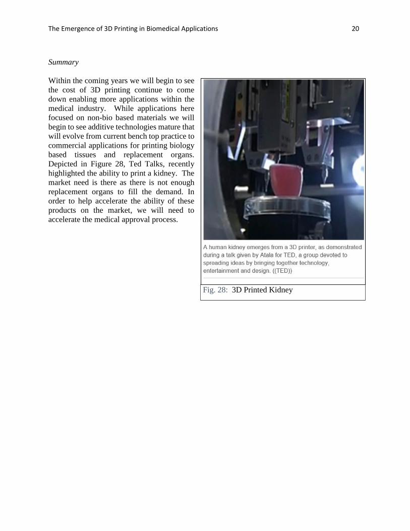
Summary
Within the coming years we will begin to see
the cost of 3D printing continue to come
down enabling more applications within the
medical industry. While applications here
focused on non-bio based materials we will
begin to see additive technologies mature that
will evolve from current bench top practice to
commercial applications for printing biology
based tissues and replacement organs.
Depicted in Figure 28, Ted Talks, recently
highlighted the ability to print a kidney. The
market need is there as there is not enough
replacement organs to fill the demand. In
order to help accelerate the ability of these
products on the market, we will need to
accelerate the medical approval process.
Fig. 28: 3D Printed Kidney

The Emergence of 3D Printing in Biomedical Applications 21
References:
Atala, A. 2011. 3D Printed Kidney, Ted Talks, March
Atala, A; Murphy S., 2014 “3D Bioprinting of Tissues and Organs”, Nature biotechnology, Vol.
32, number 8, pgs. 773-785, August.
Berretta, S., Ghita, O., Evans, K.E., 2014, “Morphology of polymeric powders in Laser Sintering
(LS), From Polyamide to new PEEK powders”, European Polymer Journal, Volume 59,
October, Pages 218-229
DeSimone, J., 2014 “What if 3D printing was a 100X faster”. Ted Talks,
http://www.ted.com/talks/joe_desimone_what_if_3d_printing_was_25x_faster
Eggbeer, D., Bibb, R., Evans, P. & Ji, L. Evaluation of direct and indirect additive manufacture
of maxillofacial prostheses. P. I. Mech. Eng. H. 226, 718-728 (2012).
EOS and OPM case study, 2014. July. http://www.eos.info/case_studies/customized_3D-
printed_polymeric_cranial_implants
EOS and Alphaform case study, 2015, Jan. http://www.eos.info/case_studies/cranial-implants-
produced-with-additive-manufacturing
Felix, 2013. “3D-Printed Polymer Skull Implant Used For First Time in US”. Science World
Report. http://www.scienceworldreport.com/articles/5441/20130307/3d-printed-polymer-skull-
implant-used-first-time.htm
Ganey, T., 2011. “Cell proliferation and vitality determination of osteoblasts on different
materials and surface characteristics; Interpretation of laboratory data”, Confidential OPM
Report- March.
Ghita, O., E. James, R. Davies, S. Berretta, et al., 2014 “High Temperature Laser Sintering (HT-
LS): An investigation into mechanical properties and shrinkage characteristics of Poly (Ether
Ketone) (PEK) structures”, Materials & Design, Volume 61, September, Pages 124-132
Hahn, B.D., Park, D. S., Choi, J. J., et al, 2013. “Osteoconductive hydroxyapatite coated PEEK
for spinal fusion surgery”. Applied Surface Science. Volume 283. 1. October, Pages 6-11
Hanson, K., 2013. “First 510(k) Clearance for Customized 3D-Printed Polymeric Cranial
Implants”, Medical Design Technology, November.
He, Y., Xue, G. & Fu, J. 2014. “Fabrication of low cost soft tissue prostheses with a desktop 3D
printer”. Nature. Science Rep. 4. 6973. DOI:10.1038/srep06973.

The Emergence of 3D Printing in Biomedical Applications 22
References continued
Hiemenz, J. 2014, “3D Printing with FDM, How it Works” white paper Stratasys Inc.
http://www.stratasys.com/~/media/main/files/white%20papers/ssys-wp-3dp-howitworks-09-
11.aspx
Itero. 2014, website http://www.itero.com/download/M20240RevA_122012.pdf
Leaversuch, R., 2001 “Demand Surge Tightens PEEK Supply”. Plastics Technology. July.
Makerbot website, 2014. http://www.makerbot.com/uses/for-professionals
Stryker website, 2014, http://www.stryker.com/en-
us/products/Craniomaxillofacial/MEDPOR/MEDPORCranialNeurosurgicalImplants/index.htm#
Sundseth, J., & Berg-Johnsen, J., 2013. Prefabricated Patient-Matched Cranial Implants for
Reconstruction of Large Skull Defects. Journal of Central Nervous System Disease, 5, 19–24
Tumbleston, J., et al., 2015 “Continuous liquid interface production of 3D objects”. Science 347.
1349.
Within Technology, 2014 “Osseointegration by Design”