bike, scooter, and chopper projects for the evil...
TRANSCRIPT

Section 5
Electric Power
207Copyright © 2008 by The McGraw-Hill Companies, Inc. Click here for terms of use.

Project
11:
Sparky
Minibike
Project 11: Sparky Minibike
The goal of this project is to arm you with the necessary
information and skills to create your own fun electric
vehicle (EV) from scratch. There are many inexpensive
electric scooters and pocket bikes available, but let me
assure you that the acceleration, hill climbing ability, top
speed and overall durability of these units cannot match
the quality of a home-built unit such as Sparky.
Of course, these traits are dependent on your choice of
drive motor, batteries and overall gear ratios, but even
with a small investment in time and money, you will be
able to build a one of a kind EV that can climb hills with
ease, operate for well over an hour on a single battery
charge, accelerate with enthusiasm, and be able to
take on most terrain without falling apart. Unlike
petrol-burning mini bikes, the electric motor and
transmission system used in Sparky are so quiet that the
only sound made by the unit is the sound of the wheels
hitting the pavement, even at full speed. This silent
operation allows the unit to be ridden practically
anywhere without polluting the area with noise. Your
neighbors and the general public will likely not be
annoyed with this type of quiet EV.
Unlike many of our do-it-yourself plans, this project
does not require a rigid set of materials and
measurements, since the goal is to build the electric
vehicle to your standards using the parts you have
available. Sure, you could build an exact replica of
Sparky by following the instructions, but with the great
availability of various small electric motors, batteries and
wheels, why limit yourself to a single design? You may
want to build a smaller EV for youngsters to ride at
camp, convert an old gas mini bike to electric for hunting
or trail riding, or go all the way and build a fully street
legal motorcycle—this is all possible by choosing the
appropriate parts. When I built Sparky, my goal was to
pack as much power, range, and ruggedness as I could
into the smallest possible size, and with a top speed of
approximately 31 mph (50 km/h), streetbike-like
acceleration, and a full hour run time on a charge. To add
icing to the cake, I accessorized Sparky to resemble a
pint-sized Harley fat boy, complete with tree-trunk front
forks, large fenders, and an old-school-style seat.
Electric motors have nothing in common with their
gas-powered counterparts, even though they both may be
rated in horsepower (HP) and rotations per minute
(RPM). At only 2.5 HP, the coffee-can-sized motor used
on Sparky will generally outperform a 5 HP gas engine
(commonly used on go-carts), especially during
acceleration. Motor controllers are another alien
technology, especially if you have worked on
gas-powered vehicles before, but don’t worry, it will all
be explained in this section, which is why the best way to
approach this plan is by reading the entire text all the
way through in order to understand the technologies
used, and to see why I choose the parts used to build
Sparky. Once you understand the core technologies and
components needed, you can build a small electric mini
bike just like Sparky, or create your very own custom
electric monster from scratch.
The batteries like the ones shown in Figure 11-1 are
probably the most important component in any electric
vehicle, large or small. If your batteries cannot deliver
Figure 11-1 Two 12-volt GEL batteries
208Copyright © 2008 by The McGraw-Hill Companies, Inc. Click here for terms of use.

Project
11:
Sparky
Minibike
the needed amperage, then it really does not matter how
powerful your drive motor is. One should not compare
battery size to gas tank capacity on a gas-powered
vehicle, since a teaspoon of fuel will run a gas-powered
engine at full power, even if for a limited amount of time,
whereas a tiny battery will simply fail to turn an electric
motor at all. Batteries are rated in voltage and amp hours,
and these two variables will determine how fast your
motor will turn, how much horsepower it will deliver
(more on this later), and for how long. OK, get out your
pocket protector; things are going to enter the “nerd
zone” for a while!
Although the “fuel” for an electric motor is a function
of the amperage and voltage of a battery, there is no way
of comparing this to a simple tank of gas. If I had to
guess, then I would estimate that amperage is the
quantity of fuel per hour delivered to a gas engine, and
the voltage is the octane, or burn quality, of the gas. The
more amperage a battery can deliver, the more torque the
motor shaft will deliver, and the more voltage this
amperage is delivered with, the faster the motor shaft
will spin. Although this is an oversimplified explanation,
it does hold true for many of the small electric DC
motors you will have to choose from when sourcing parts
for your mini bike. Before you can choose a motor, or the
appropriate batteries, you should know the basic facts
and formulas dealing with amps, watts, volts, and
horsepower.
Watts
Most small, electric, direct current (DC) motors are rated
in watts, and wattage is derived by multiplying voltage
by amperage (volts × amps). So, if a motor claims that it
will deliver 900 watts at 36 volts, then you know it will
take 25 amps from your battery pack (900 watts divided
by 36 volts). This simple formula works, as long as you
know any two pieces of the watts, volts and amps puzzle.
Remember that 250-watt light bulb in your garage? Sure,
just divide 250 watts by 120 volts, and you will then
know that your light bulb needs just over 2 amps to
operate. The wattage ratings of a DC motor is the most
important of all ratings, and this value will determine the
size and type of battery and motor controller needed, as
well as the overall performance of the vehicle. The motor
I used on Sparky is rated at 2000 watts continuous.
Horsepower
This rating isn’t really very useful in the electric motor
world, since an electric motor’s horsepower is rated at
zero RPM under load, whereas a gas engine’s
horsepower is rated at its maximum RPM under no load.
What this means is that an electric motor rated at the
same horsepower as a gas engine will put the gas engine
to shame when it comes to acceleration and torque.
To make things even more confusing, gas-powered
engines are rated at their peak horsepower, while electric
motors are rated at their continuous rated horsepower.
The peak horsepower of an electric motor is usually
8 or 10 times its continuous rating, so this makes an
electric motor of an equal horsepower seem all the more
powerful. If you really want to rate your motor in
horsepower, or find one that is rated in this way, then you
can convert by using the ratio of 1 horsepower equals
approximately 746 watts. To compare this to a gas
engine, I like to assume that a 1-horsepower electric
motor will feel like a 3-horsepower gas engine. The
motor used on Sparky is 2000 watts, so this works out at
2.68 horsepower (2000 watts/746), which should seem
like a gas engine of approximately 8 horsepower.
Amperage ratings
Battery amperage may be stated in various ways
depending on the intended use for that particular battery.
You will see things like CCA (cold cranking amps),
MCA (marine cranking amps), RC (reserve capacity),
and AH (amp hours). It is the last rating, AH (amp
hours), that we are really interested in because this is the
maximum energy that can be delivered from the battery
every hour. By knowing the power rating of the motor,
we can figure out the minimum run time for your vehicle
before it needs a recharge. I say minimum run time
because your motor will not always need maximum
amperage, and if you are not climbing large hills, or
driving like a stunt person all of the time, you may only
be using a small percentage of the motor’s rated current.
Using a few of the above formulas on Sparky’s
2000-watt motor, I can determine that it will draw a
maximum of 83.33 amps at its rated 24 volts (2000 watts
24 volts), and since my battery pack can deliver 32 amp
209

Project
11:
Sparky
Minibike
hours, I would expect a run time of only .38 hours, or
about 20 minutes (32 AH/83.33 amps). This assumes that
I am forcing the motor to work at its full rated capacity at
all times, and this is never the case; in reality, I typically
get 1.5 hours or more between charges, even when
spinning up dirt and pulling wheelies. A realistic measure
of run time between charges will be something you will
have to find out from actual use, as it will certainly vary.
Voltage
Each battery has a rated voltage, with 12 volts being the
most common for batteries typically needed for small
electric vehicles. Since most small electric motors run at
voltages between 24 and 48 volts, you will have to
connect two or more batteries in series to achieve the
required voltage rating for the battery pack. A series
connection means that the positive terminal of battery #1
connects to the negative terminal of battery #2, and
power is taken from the free terminal of each battery
(one positive, and one negative). In series, a battery
cannot deliver any more amp hours than the rated
capacity of a single battery, but it does double the
wattage available because it also doubles the voltage. My
two batteries shown in Figure 11-1 are rated at 12 volts,
and 32 amp hours each, so in series they deliver 32 amp
hours at 24 volts, or 768 watts (24 volts × 32 amps).
A single battery would only deliver 384 watts (12 volts ×32 amps). If wired in parallel (not recommended), the
batteries would double their amp hours to 64, but the
voltage would remain at 12 volts, so they would again
deliver 768 watts (12 volts × 64 amps). Parallel wiring
of batteries should never be done, since one battery may
try to charge the other if they are not equal, which could
result in damage, heat, or fire. To sum this up, you will
need to connect as many 12-volt batteries in series as
necessary, in order to achieve the desired voltage, but
your overall amp hour capacity will be the same as one
single battery can deliver.
Battery type
Not all 12-volt batteries are the same, and this fact is
largely reflected in the price. Typical car batteries are not
well-suited for electric vehicle use, even though their
price may be inviting. A car battery is made to deliver an
enormous amount of power in a very short time and then
become fully charged shortly after. As many of us know,
a car battery will be destroyed if run completely down
more than a few times in a row, which is why it will not
be a very good candidate for our purpose. Car batteries
are also very messy, require some fluid maintenance, and
do not like vibration or uneven mounting. A much better
choice for your battery needs is the non-spillable, sealed,
GEL deep cycle battery. These batteries have no
removable tops since they contain no liquid (it is in a
gelled state)—they can be mounted in every orientation
except upside down, they can withstand moderate
vibration, and they can be depleted completely many
times without damage. These batteries are commonly
rated as marine or wheelchair-use batteries, and the
smaller units may be rated for security or battery backup
use. They are more expensive than conventional car
batteries, but will outlast them many times over,
especially in our electric vehicle. Multiple batteries
should always be the same type, and approximately the
same age, especially when charging them together as a
24 or higher voltage pack.
Charger
The best way to charge your batteries is together as a
single pack, so if your battery pack voltage is 24 volts,
you will need a 24-volt charger. These are readily
available, and often you can find older ones at
secondhand stores, or from shops that repair or sell
wheelchair parts. A common 12-volt charger used for a
car battery will also work, but you will either have to
charge one battery at a time (very slow), or purchase two
chargers and run them both, one on each battery.
Whichever you choose, the charger should be fully
automatic, shutting off when the battery is at peak
capacity in order to avoid damage from overcharging.
Only the worst chargers available will not have a current
meter or automatic shutoff, and these should be avoided.
Also, make sure that the charger you have is rated for the
type of battery you are using, such as wet lead acid, or
sealed gel.
I hope that wasn’t too much nerd jargon in such a
small space! It really does help to know what to expect
from batteries and motors before you start searching for
210

Project
11:
Sparky
Minibike
parts, and the above information is the basic lingo you
will have to know when searching the numerous sources
for motors and batteries for your vehicle. I still
recommend that you read this entire plan before sourcing
any parts, as there are more tips and facts further ahead
that will help you beat the pitfalls of part sourcing, and
avoid many common mistakes while hunting for parts.
As the build progresses, each major component will be
described in more detail. Hey, buddy, put that furnace
motor down and read the rest! It wouldn’t work for this
project anyhow, trust me.
Once you have read through the entire plan, and
started from the beginning, you will probably have
chosen a motor and the appropriate batteries to achieve
the desired acceleration and run time for your mini bike.
The batteries make up the bulk of the weight and size, so
we will start by building a strong cage or battery box to
hold them together as a single unit. A battery box can be
easily removed from the rest of the frame for charging,
transporting the mini bike, and allowing you to have
multiple packs for continuous non-stop fun. A nice
battery box can be made by forming a base, like the one
shown in Figure 11-2, from some 1-inch, 1/16-inch-thick
angle iron. You will want to cut the pieces, as shown in
Figure 11-2, so that the battery sits into the base of the
box, but not too tight that it becomes stuck. The inside
measurement of the box should be at least 1/8-inch larger
than the battery.
The four pieces of angle iron that make up the battery
box base are shown in Figure 11-3, tack welded together
at the corners. The angle iron could have also been
formed by cutting the ends at 45 degrees, but I find this
way to be a bit more tolerant of small errors that could
make the box too small for the batteries to slide in
easily. With only the corners tack welded together, it
Figure 11-2 The base for the battery box
Figure 11-3 Welding the battery box base pieces
is easy to force the box into a square by tapping it with a
hammer.
Before you completely weld the battery box base
together, test fit one of your batteries to make sure that it
is snug, but is not wedged in too tight. As shown in
Figure 11-4, my 32-amp-hour GEL battery drops right
into the base with approximately 1/8-inch clearance
between the battery edges and the angle iron. Once
tested, you can weld the outside corner and underside of
all joints to complete the base of the battery box. Do not
weld the inside joints, or your battery may not fit. For
reference, my battery measures 7.75 by 6.5 inches, and is
6 inches tall to the top of the terminals.
As stated earlier, my battery pack will be made from
two series-connected, 32-amp-hour, deep-cycle,
Figure 11-4 Testing the battery fit
211

Project
11:
Sparky
Minibike
GEL-type batteries at 12 volts each. The resulting battery
pack will be able to deliver 32 amps at 24 volts for one
hour, or any ratio of 32:1 up to the battery’s maximum
discharge ability, for example, 64 amps for 30 minutes,
or 16 amps for two hours. The current draw from the
motor during typical riding will vary quite a bit, with
acceleration from a dead stop requiring the most current,
and cruising on the flats without any headwind requiring
very little current. Your ultimate acceleration will depend
on your battery pack’s maximum current discharge, and
the maximum current that will flow through your motor
controller if you decide to use one.
On a small electric vehicle like Sparky, the maximum
discharge of most deep cycle batteries will be more than
enough for powerful acceleration, bordering on the
wheelie zone, but don’t expect to throw on a huge
amp-hungry motor and a pair of tiny batteries and have
them deliver 900 amps in one minute just because they
can deliver 15 amps in one hour—there is a limit. If you
really want to know what the maximum discharge
capacity for your battery is, then you will probably have
to spend some time digging around on the
manufacturer’s website.
The sides of the battery box are made from the same
1-inch angle iron as the base, and are welded at each
corner to continue the box upward along the corners of
both batteries, as shown in Figure 11-5. The top of the
box should be at least half an inch higher than the top of
the battery terminal to protect the terminals from the rest
of the frame. I made these four side pieces 14 inches in
length for my battery pack. The four side pieces are first
tack welded in place, so that you can do another test fit
with the batteries before welding the outside of the joints.
There should be a bit of wood or rigid foam between the
two batteries, so that the top battery is not resting directly
on top of the lower battery’s terminal, as excessive
vibration may damage the top battery. Do not attempt to
make any welds with the batteries installed or they
will melt!
The top of the battery box is made by welding flat bar
of the same thickness as the angle iron across the top, as
shown in Figure 11-6, so that it completes the box.
Flat bar is needed since angle iron would make it
impossible to install the batteries due to the lip it creates.
If you do not have any scrap bits of flat bar to use, you
can cut the angle iron along the edge with a grinder disc
to make two pieces of flat bar from it. Again, it’s a good
Figure 11-5 Installing the battery box sides
Figure 11-6 Finishing the battery box
idea to tack weld and test fit before committing any
welds, just in case you need to make a few adjustments.
Once everything is looking good, make the final welds
and clean up the joints with a sanding disc, as shown in
Figure 11-6, to complete the battery box.
Once you have the battery box completed and have
chosen a drive motor (or at least know the measurements
212

Project
11:
Sparky
Minibike
of the drive motor), you can begin working on the frame.
My goal was to build the smallest frame possible around
my battery pack, drive motor and motor controller
without an inch to spare. I thought it would be fun to
have a cute-looking “mini hog” that would look as
though it was a kids’ toy, but have more than enough
power to leave any department store scooter or pocket
bike whimpering in the dust during a race.
My original electric mini bike had a frame made of
square tubing, but this time I wanted a little more style,
so I decided to go with a nice curved “spine” over the top
that would define the general proportions of the rest of
the frame. To achieve this without a pipe bender, I
bought two 1.5-inch thin walled electrical conduit (EMT)
elbows from a hardware store. In Figure 11-7, I marked
the area of each elbow that I planned to cut, in order to
weld them together to form the appropriate sized spine
for my frame. If for some reason you cannot find EMT
where you live, then any 1/16-inch walled mild steel
tubing (even square) would work. You could even
butcher a mountain bike frame for the large tubing used
in the frame.
Feel free to experiment with your own frame designs.
As long as you build the frame around your key
components in such a way that everything fits together,
and so that your belt or chain will have adequate
clearance, your imagination can run wild. As you read
on, you will see why I chose the size and style of
materials I did, but you could use the same techniques to
create a variation of Sparky, a full-size motorcycle, a
chopper, or even a four-wheel go-cart if you wanted to.
Since I was going to build the frame spine over the
main components, then build the rest of the frame around
Figure 11-7 A pair of 1.5-inch conduit elbows
this configuration, I only tack welded the two elbows
together at this point, just in case I decided to cut them
shorter. As shown in Figure 11-8, there would be plenty
of length for the battery box, drive motor and rear wheel
under this smooth-flowing spine. It’s always easier to cut
the excess away after you have a plan, rather than being
stuck with a piece that’s too short.
Figure 11-9 shows visually how I attack a frame when
I have no plan, but do have most of the components.
Since the battery box would require the most space, and
dictate the overall height of the frame, it was important to
finish it first so that the other components could be
placed around it. My goal was to pack as much “stuff”
into the smallest area possible, so it was very important
to lay out the frame like this, just in case something
unexpected came up. The space between the battery box
and the rear wheel is the amount of space the motor will
occupy, and although my motor was still on order from
the supplier at the time, I had detailed drawings, and
knew the exact size and shape. With the motor installed
directly between the rear wheel and the battery box, there
would be just enough room above the motor for either a
large motor controller, or an automotive solenoid,
depending on which way you plan to control the current
Figure 11-8 Elbows tack welded together
Figure 11-9 Visualizing the frame layout
213

Project
11:
Sparky
Minibike
(more on this later). This curved spine was a perfect fit
because it placed the rider low over the rear wheel, and
then made a nice flowing curve over the battery box, so
that the final mini bike would be very strong yet stylish.
Even though I was satisfied with the main spine,
I decided to leave it uncut for now. You just never know
how things are going to progress when you tackle a
project like this without a rigid plan, and sometimes the
best ideas present themselves randomly as your build
progresses. This ability to build a custom project, just
like an artist paints a picture from scratch, is the very
skill that will set you apart from those that can only build
from a strict set of plans dictating every single cut and
exact parts. Trust your instincts, and don’t be afraid to try
new things!
The main spine is the kingpin tube for the entire frame,
and all the other tubing simply flows around the main
components, basically holding the guts in place like a
ribcage. The two diagonal tubes shown in Figure 11-10
are called the “down tubes,” and they will connect to the
front of the main spine just behind the head tube, and run
at an angle to the bottom sides of the battery box. If you
look at most motorcycle frames, you will see a very
similar geometry to many frames, but the gas engine is
where the battery box in our vehicle will be. These tubes
do not have to be nearly as strong as the main spine since
they are mainly there to “hang” the battery box, so I
made them out of two lengths of ¾-inch thin walled
electrical conduit. Again, if you have no source for EMT,
then any thin walled mild steel tubing will do the trick,
and a perfect candidate would be the tubing used for the
seat tube in a bicycle frame.
The lengths of both tubes will depend on the height of
your battery box, the goal being an inch or so longer than
the diagonal distance across the top and bottom, as
shown in Figure 11-10. For the record, I cut my two
tubes at 16 inches each to clear my battery box and allow
a bit of space to work with. Both tubes will be fish
mouthed to form a joint with the other frame tubes at a
later time, so a little bit of length will be lost.
The down tubes will connect to the bottom tubes,
which will travel under the battery box and continue to
the rear of the frame, where they will hold the rear wheel
bearing mounting plates. For this reason, the bottom
tubes are made from slightly heavier tubing than the
down tubes, but do not need to be as large as the main
spine tube. As shown in Figure 11-11, I cut two lengths
Figure 11-10 These will be the down tubes
Figure 11-11 Preparing the down tubes and bottom tubes
of 1-inch thin walled electrical conduit to be used as the
bottom tubes, and then I made the appropriate fish-mouth
cuts in the down tubes to form a proper joint for
welding.
The bottom tubes need to be long enough to make the
distance from the front edge of the down tubes, under the
battery box and drive motor, and then past the area where
you plan to mount the rear wheel bearings. It’s best to
read ahead again before you choose a length to cut these
tubes, and when you do have an idea as to how long they
need to be, add at least 6 inches extra just in case (you
can always chop it off later). By the time you get to
Figure 11-16, the function and length of the bottom tubes
will be clear. My bottom tubes were cut to a length of
20 inches.
Nothing screams out homemade more than an
unpainted frame or a frame with open-ended tubing.
Open-ended tubing is sharp, prone to filling with dirt or
water, and not as strong as capped tubing. It is really easy
214

Project
11:
Sparky
Minibike
to plug the end of a round tube by simply welding an
appropriate sized washer over the end. As shown in
Figure 11-12, I tack welded a pair of washers over each
end of the bottom tubes. It is much easier to get this done
ahead of time, since you can work with the tubing on
your bench as a single unit. Once welded to the frame, it
will be difficult to get your grinder into position. Get
’er done!
The tubing caps are welded all the way around then
ground down, as shown in Figure 11-13. The completed
product looks very professional, and will resist filling
with debris when you ride, and will not be a source of
danger if for some reason the frame ever came in contact
with somebody. You could also fill the washer holes if
you like, but I decided to leave them as they are, just in
case I want to add a few accessories, such as reflectors or
lights to the frame.
Figure 11-12 Plugging up open tubing ends
Figure 11-13 Washers welded and ground
As stated earlier, the bottom tubes will connect to the
base of the down tubes and travel under the battery box
to the rear of the frame, so they need to be welded, as
shown in Figure 11-14. I chose an angle of 90 degrees so
that the down tubes run directly along the front of the
battery box up to the main spine tube. This allows the
most compact configuration possible, placing the front
wheel very close to the front of the battery box. On many
motorcycle frames, the down tubes travel from the base
of the engine towards the head tube at a slight angle, and
the front wheel has several inches of clearance between
the motor and frame due to the rake of the front forks.
More front fork rake generally means a more stable bike
at higher speeds, but my goal for design was size, and I
did not plan to hit the highways or break any speed
records, so minimal rake would be fine. Again, feel free
to experiment with your own design, and look at other
mini bike and motorcycle frames for ideas. Wouldn’t a
chopper be cool? You know it!
Once the down tubes and bottom tubes are welded
completely around and ground clean, they will be
installed, as shown in Figure 11-15, so that the bottom
tubes continue to the rear of the frame, and the down
tubes travel along the front of the battery box at a
diagonal angle to meet just under the main spine tube.
You may want to clamp the down tubes to the bottom of
the battery box, just so they stay in place while you test
fit the rear wheel and make the other tubes for welding.
You may also want to grind the tops of the down tubes to
form a good joint for welding with the main spine tube,
Figure 11-14 Joining the down tubes and bottom tubes at
90 degrees
215

Project
11:
Sparky
Minibike
Figure 11-15 Laying out the frame tubing
but don’t do this until you visually lay out the rest of the
frame, as will be shown next.
The next weld you make will pretty much dictate the
final shape of the frame, position of the rear wheel and
maximum motor size that you can install into the frame.
As shown in Figure 11-16, it’s important to visually
check your layout before making any final welds, just in
case your drawing or rough plan is not as accurate as you
might have thought. There are some potential problems
that may not be obvious in a drawing. Will the rear wheel
slide out of the frame? Will the inflated tire rub on the
Figure 11-16 Installing one of the truss tubes
bottom tubes with pressure applied? Can the battery box
slide out of the frame easily? Once the rear bearings are
installed, will the rear tire clear the back of the main
spine tube? As you can see, the only way to feel
confident about committing to a final frame design is to
try to answer all of these questions visually.
You should try to set up the mini bike using as many of
the main components as you can, such as the rear wheel,
axle, bearings, and motor before welding the top of the
down tubes to the main spine tube. Don’t forget about
fender, sprocket or pulley clearances, and brake drum
arms if your wheel has one.
Figure 11-17 shows the clearance above the battery
box and main spine tube after tack welding the frame
parts together, based on the visual layout in Figure 11-16.
I ended up with a quarter inch just above the top of the
battery box, which would be plenty of room to allow the
quick removal of the pack for charging or swapping.
Make a few good tack welds between the down tubes and
the spine tube to hold it in place and allow for any
alignment fine tuning. Alignment should be checked from
directly above the frame as well to make sure that both
bottom tubes are parallel to each other, and that the spine
tube runs right down the middle of the bottom tubes.
At this stage, it is easy enough to manipulate the frame to
get it back into alignment, but if it is too far out, you are
better off breaking the tack welds and redoing them. The
best welders are not those who get things perfect on the
first try, but those who fix all their mistakes.
To add a bit of style to the little frame, and make good
use of the mountain bicycle frame to be used for the head
tube, I decided to recycle the fork legs for the last part of
the frame, which I will refer to as the “rear tubes” from
now on. The rear tubes will complete the frame by
Figure 11-17 Tack welding the frame together
216

Project
11:
Sparky
Minibike
fastening the rear of the bottom tubes to the rear of the
main spine tube and allowing a place for the bearing
mounting plates to connect, if your design calls for them.
Although you could have simply used a few lengths of
1-inch or 3/4 EMT for this part of the frame, the fork legs
offer a nice tapered and flowing look to the overall
design that perfectly complements the curve of the main
spine. Remember that building a custom is an art, not a
rigid set of rules!
When cutting fork legs, try to get as close to the stem
as possible without cutting into the stem, because we will
later use that stem to create the triple-tree fork. You can
also cut off the fork dropouts as close to the end as
possible, and add them to your ever growing pile of parts
for some other project. Figure 11-18 shows the legs cut
away from the stem with minimal waste. I make all my
cuts with a 3/32 cut-off grinder disc, but you could also
do this with a hacksaw if you are worried about slicing
into the stem.
As shown in Figure 11-19, the fork legs will form the
rear tubes by completing the main frame. There is no
Figure 11-18 A de-limbed mountain bike front fork
Figure 11-19 Positioning the rear tubes
magic measurement dictating where on the main spine
tube the fork legs should be placed, but it is important
that when welded to the bottom tubes, the axle will end
up in the correct position to allow for adequate clearance
between the motor and rear tire. I have built enough
custom designs from drawings and sketches to know that
you can never fully trust your two-dimensional drawings
for accuracy, especially when working with such a
compact design. The only way to be certain that all the
components will live together in harmony is to lay out
the frame visually again. It is a bit annoying to get out all
the parts and prop them all up again, but this sure beats
the disappointment that you will feel when your only
option is to cut fully welded tubing later (my first-hand
experience).
As shown in Figure 11-19, I decided to place the fork
legs (rear tubes) up as far as length would allow along
the main spine tube, so that it would look like the legs
were flowing directly from the top curve of the frame.
There is adequate clearance between the tire rubber and
the tubing, and enough room for my belt drive to be
installed on the axle without rubbing on any of the
tubing. Things are very close, but by visual inspection, I
expected to have no problems with this design.
Even though the mock layout seemed perfect, I only
tack welded the rear tubes in place, as shown in
Figure 11-20. The tack welds are strong enough to handle
the frame without fear of misalignment, but allow for
easy adjustment or removal if something unexpected
Figure 11-20 Tack welding the frame tubing
217

Project
11:
Sparky
Minibike
happens. At this point, I cut some of the excess rear spine
tubing away, but left all the bottom tube length extending
past the rear axle area, as I thought it would look cool in
the final design, almost like a pseudo exhaust pipe. My
goal was a small yet powerful mini bike that would
resemble a Harley, so this was a bonus.
Figure 11-21 shows the head tube and fork stem taken
from the unfortunate mountain bicycle that I mercilessly
butchered for parts. The length of the head tube is not
important, but it is important that the fork stem and head
tube form a matching pair. If you have taken both parts
from the same bicycle, then you have no worries, but if
not, install the bearing cups and all the hardware to
ensure that the fork stem isn’t too short. In Figure 11-21,
I already ground off excess tubing from both the head
tube and the fork stem. The little ring just above the fork
stem (bearing race) has been tapped off with a hammer in
order to avoid damage when grinding.
There are numerous ways to create the forks for your
electric mini bike. You could simply use a set of bicycle
forks as they are, as long as the front wheel will fit.
You could bend a few tubes and weld them back onto the
fork stem to create a wider bicycle-type set of forks, or
even install an actual motorcycle front fork. I decided to
go with the conventional triple-tree-type fork that you
see on almost all motorcycles and even some hardcore
mountain bikes. A triple-tree fork is very strong, looks
like it means business, and is really not all that hard to
make, requiring only the fork stem you already have and
a few plates cut from some scrap 1/8 sheet metal.
As shown in Figure 11-22, the tree plates are drawn
out on the plate using your fork leg material and the fork
stem as a guide. There is no need to give you a drawing,
since the exact size of the plate is based on the width that
the fork legs need to be so that they are positioned on
Figure 11-21 Fork stem and compatible head tube
Figure 11-22 Cutting the triple-tree plates
each side of the front wheel with adequate clearance.
Determine the height of the plate so that the distance
between the center of the fork stem circle is one inch
from the center of the fork leg circles, as shown in
Figure 11-23. There is a quarter inch of material left
around the fork stem hole, since it will be drilled out of
the plate.
The triple-tree plates are cut using either a jigsaw or
zip disc, but before you start cutting, read ahead so you
can see why the plates are made this way.
The top-tree plate is cut in a certain way so that it will
be placed over each fork leg, while the bottom tree plate
is cut so that it can be welded directly to the inside of the
fork legs. The top plate also needs to slide over the fork
stem at the threaded area, so the hole needs to be cut out.
Because I used the same 1.5-inch EMT for the main
Figure 11-23 Triple-tree and top-tree plates cut from sheet
metal
218

Project
11:
Sparky
Minibike
spine, this is how I cut and ground both plates. With a
front wheel width of approximately 4 inches, and a fork
leg width of 1.5 inches, my top plate had an overall
dimension of 7.5 inches in width and 3 inches in height.
You may want to use thinner tubing for the front forks,
and may have a completely different size and style of
front wheel in mind, so your tree plates may be a lot
different to mine. Again, the best way to test your
dimensions before cutting is by visually laying out the
wheel and fork legs to see what type of distance you need
between the front fork legs. Shoot for at least a quarter
inch of clearance between the edge of the front tire and
the fork tubing. This way, you can add fenders later.
If you do not have a hole saw of the correct size for the
fork stem hole, drill a series of small holes around the
inside of the traced area, and then tap the hole out with a
hammer. In Figure 11-24, I punched several points along
the inside of the line to drill them out with a 1/8-inch
drill bit.
This crude hole cutting method works well when you
aren’t in the mood to spend the day driving around
looking for the perfect hole saw, which will usually wear
out after three uses anyhow. Once the area is drilled,
punch out the center, as shown in Figure 11-25, and then
file off the teeth with a round file. Building a custom can
be a lot of work, but like most artistic projects, if it was
too easy, then everyone would be doing it. All this
tedious work will eventually pay off.
Figure 11-26 shows how the triple-tree plates will be
connected to the fork stem. The top plate is held in place
by the fork stem hardware, and the bottom plate is
welded directly to the base of the fork stem where you
removed the original fork legs. If viewed from the top,
both plates would be in perfect alignment, since the
center of the fork stem passes through them at the same
Figure 11-24 Cutting the fork stem hole from the top-tree
plate
Figure 11-25 Hole ready for filing
Figure 11-26 Tack welded triple tree
point. As you can see, if the top plate covers the top of
the fork legs, then the fork legs continue to the bottom
plate, cradled by the cut-out area so that all three tubes
(fork legs and fork stem) remain parallel to each other.
Test the position of the bottom tree plate by placing
both fork legs in position to check parallel alignment.
Once you have the bottom plate in the correct position,
tack weld it in place, as shown in Figure 11-26.
Once you have the bottom plate tack welded in
position, and have checked the alignment of all three
tubes, weld the entire joint, as shown in Figure 11-27.
There may be a small amount of distortion to the bottom
plate from the welding heat, but this will not present a
problem, since the distortion will be the same on both
sides, and have almost no effect on the alignment of the
forks.
I decided to use the same 1.5-inch thin walled
electrical conduit tubing as used for the top spine tube
219

Project
11:
Sparky
Minibike
Figure 11-27 Bottom tree plate welded in place
when making my front forks, in order to get the thick “fat
boy” look in my final design. On a mini bike of this size,
1-inch conduit would have been strong enough, but the
difference in weight between the two sizes of tubing was
miniscule. Rather than trying to calculate the exact
length for the fork tubes at this point, I simply cut them
longer than they would need to be by placing the frame
on blocks to estimate ground clearance, and measuring
from the top of the front spine tube where the head tube
would be installed. Although my final fork length was
17.5 inches, I gave myself plenty of room to work with
and cut the two tubes, as shown in Figure 11-28, to 24
inches long each.
Since the front fork tubes need to be held in place by
the top-tree plate, we will need to figure out a way to
achieve this, while still allowing the assembly to come
apart for removal. Weld a pair of nuts to a pair of washers
that will be welded to the top of the fork tubes. As shown
in Figure 11-29, a pair of half-inch nuts and bolts and
some 1.5-inch washers will do the trick. The washers do
not have to be exactly 1.5 inches in diameter, just
something close enough so that you can weld them to the
top of the fork tubes, or directly inside them. If you are
Figure 11-28 Fork leg tubing
Figure 11-29 Half-inch bolts and 1.5-inch washers
using other fork tubing, then choose appropriate width
washers.
The first step is to weld the nuts to the washers so that
the bolts can be placed into the nuts through the washer
holes. A good way to make sure the nut is in the correct
position is to hold it in place by the bolt while you are
welding it. The final product will look like Figure 11-30.
The washers will now be welded to the top of the fork
tubing, as shown in Figure 11-31, so that the nuts are
inside the tubes (right in Figure 11-31). Weld the joint all
the way around and then grind the area clean, so that it
looks presentable and creates a flush top surface to mate
with the triple-tree top plate (left in Figure 11-31).
The fork tubes will be held in place by the top-tree
plate, as shown in Figure 11-32. Not much to say here: if
all went well, the bolts will thread right in. If the bolt
seizes, remove it and look at the nut threads for any
welding spatter that may have found its way inside and
remove it with a pick.
Figure 11-30 Weld the nuts to the washers
220
Project
11:
Sparky
Minibike
Figure 11-31 Welding the washers to the top of the fork tubing
Figure 11-32 Test fitting the fork tubes
Now install all the fork hardware and let the lower tree
plate cradle the fork legs, as shown in Figure 11-33. Both
fork legs and the head tube should be in perfect alignment
with each other, once the lower plate is fit snuggly
against the fork tubing. You can now weld the lower tree
plate in place while the fork hardware is holding
everything in place. A light bead on the underside of the
plate is all that is necessary for strength, and you should
avoid welding the top of the joint to reduce the chance of
warping the fork leg tubing. If you are worried about
Figure 11-33 Setting up the fork set for welding
warping the fork legs, tack weld a bit of plate or scrap
tubing across the ends before you weld; this also helps
hold the assembly together prior to welding.
Now that your triple-tree assembly is completed, the
head tube needs to be welded to the front of the main
spine tube. Head tube angle can have a large effect on the
overall steering characteristics of a two wheeler, so some
thought should be put into this cut. The more angles you
have, the more stable the bike will feel at higher speeds,
but the less responsive the steering will be to small
adjustments of the handlebars. With very minimal head
angle, the steering will react instantly to any small
changes in the handlebars, so high-speed riding may feel
“twitchy,” and take some getting used to. I let the front
wheel diameter dictate my head tube angle by leaving as
little space between the tire and frame as possible. My
resulting head tube angle is fairly steep, as you can see in
the final design photos, and this resulted in a fairly stable
ride that felt a little “nervous” at high speed for the first
few rides. Overall, I am happy with the steering
characteristics.
If you want to choose a head tube angle that will offer
a great ride at all speeds, simply look at the head tube
angle of a typical bicycle, and shoot for that. Extend an
imaginary line from the head tube to the ground, and use
the angle between the ground and that formed by the
head tube as your guide. For reference, this angle would
typically be between 65–70 degrees on a bicycle, and on
my Sparky it is 80 degrees.
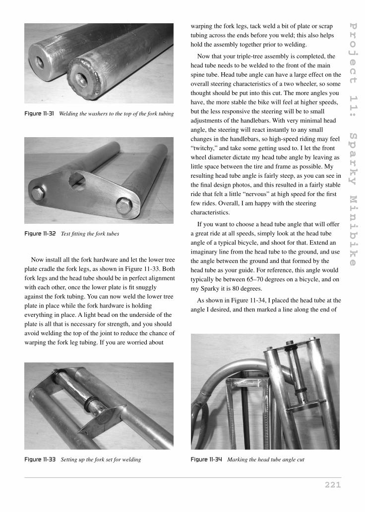
As shown in Figure 11-34, I placed the head tube at the
angle I desired, and then marked a line along the end of
Figure 11-34 Marking the head tube angle cut
221

Project
11:
Sparky
Minibike
the top spine tube showing the angle that I needed to cut
with my grinder disc.
Once you cut the spine tube at the correct head tube
angle, you will need to cut the fish mouth in order to
make a correct joint for welding. As shown in
Figure 11-35, the same amount of material should be
ground from both the top and bottom of the joint in order
to maintain the proper head tube angle. You should place
the triple-tree fork assembly into the joint often as you
grind, to make sure that you are maintaining the proper
head tube angle.
Once the end of the spine tube has been ground to
mate perfectly with the head tube, install the head tube
and tack weld it in place only at the top of the joint, as
shown in Figure 11-36. Ensure that the head tube angle
ends up being what you planned for, as well as the
alignment as viewed from the front of the frame. The
head tube and fork legs should look perfectly aligned
Figure 11-35 Head tube joint ground
Figure 11-36 Tack welding the head tube in place
with the center line of the frame, or perpendicular to
the ground. With only a single tack weld at the top of
the joint, manipulation will be easy if alignment is
visually off.
Although it is hard to tell from Figure 11-37 due to
lens distortion, my fork legs and head tube are perfectly
aligned as viewed from the front of the frame. When you
are satisfied with both the alignment of the head tube
with the rest of the frame and your head tube angle, add
two heavy tack welds on both sides of the lower part of
the joint and then recheck the works. At this point, you
will still be able to give the head tube an “attitude
adjustment” with a rubber mallet if need be.
Continue to weld the head tube to the main spine tube
by completing the top and bottom areas of the joint first,
in order to minimize side-to-side distortion due to
Figure 11-37 Checking head tube alignment
222

Project
11:
Sparky
Minibike
welding heat. Figure 11-38 shows the head tube welded
solid at both the top and bottom of the joint.
In Figure 11-39, I completed the welding around the
entire joint of the head tube, and also installed two
gussets made from some quarter-inch steel rod. The
gussets were not absolutely necessary, but my head tube
was quite long, and I do like to punish all my rides, so it
didn’t hurt to add this extra strength to the frame. Gussets
can be made from virtually any scrap you have lying
around, and can greatly enhance the durability and
stiffness of a frame.
Your choices for mini bike wheels are unlimited, with
hundreds of sizes and types to choose from. I built Sparky
from what I had lying around the shop, and the wheel
Figure 11-38 Weld the sides of the joint last
Figure 11-39 Head tube welded and gussets installed
shown in Figure 11-40 is a 10-inch diameter, 4-inch wide
scooter wheel taken from a dead shopping scooter (the
type you see in malls and on sidewalks). This wheel
represents the most unfriendly wheel possible for use on
a project like this, because it has no bearings, no sprocket
or pulley mount, and no way to install a brake drum.
I choose this route to demonstrate that practically any
parts can be hacked to fit. A much better wheel choice
can be found by typing “scooter parts” or “mini bike
parts” in an Internet search engine. Let’s talk a bit about
wheels before you start dismembering Granny’s scooter!
Wheel diameter
You could use wheels of just about any size for a
home-brew mini bike, ranging from those as small as
skate blade wheels right up to full size motorcycle
wheels, but to get the correct gear ratio, choose carefully
to keep complexity and cost to a minimum. Before you
settle on a wheel diameter, you should know your
motor’s full RPM and the desired maximum speed you
would like to reach.
To calculate how fast a mini bike will travel, you first
need to know how far your vehicle will travel when its
drive wheel makes one full rotation. I work this out using
the imperial measurement system to keep things simple.
To calculate this value (which is the circumference of a
circle), multiply the total diameter of the drive wheel by
PI (3.1415). So, for Sparky’s total wheel diameter of
10 inches, I would multiply 10 × 3.1415 to get 31.415.
This means that Sparky would travel approximately
30 inches if the drive wheel were to make one full
revolution. Since my goal for top speed was about
Figure 11-40 Rear wheel, axle, and bearings
223

Project
11:
Sparky
Minibike
30 miles per hour, I could now calculate how many
maximum revolutions per minute my drive wheel would
need to make in order to reach that speed. Since there are
63,360 inches in one mile, a distance of 30 miles would
be 1,900,800 inches in total. We know that Sparky’s
wheel would travel 31.415 inches every revolution, so
we just divide 1,900,800 by 31.415 and get 60,506,
which is how many wheel revolutions there are in the
30-mile total distance. Now divide that number by
60 minutes (60,506/60) and you get the answer in
rotations per minute (RPM), which would work out to
1,008 RPM. So to travel at 30 miles in one hour,
Sparky’s rear drive wheel must turn around
approximately 1,000 times every hour.
The simplified formula for calculating the drive wheel
maximum RPM if you know the wheel diameter (WD)
in inches, and the desired top speed (TS) in miles per
hour, would be 63,360 × TS / (3.1415 × WD) / 60.
Gear ratio
The above formula assumes that the motor is able to
directly turn the wheel at the desired RPM (1,008 RPM
in my case), but this is almost never a reality since most
small DC motors run at 3,000 RPM or more. If I connect
the 10-inch diameter wheel directly to the motor at 3,000
RPM, we could calculate the theoretical top speed by
using the following formula: 10 (wheel diameter
in inches) × 3.14 (PI) × 3,000 (RPM) / 63,360 (inches
per mile) × 60 (minutes per hour) = 89.2 miles per hour!
Much too fast for my liking, and probably not possible
due to wind resistance and friction losses anyhow. Your
only option is to reduce the ratio of motor shaft RPM to
wheel RPM, using some type of reduction system like a
belt or pulley.
Gear reduction is calculated using basic division
mathematics. If you have a gear reduction of 1:3, then
you divide the motor’s top RPM by 3, so the resulting
RPM of a motor at 3,000 RPM would be 1,000 RPM
through a 1:3 gear reduction system. What do you know,
that is just the thing I would need to give Sparky a top
speed of 30 miles per hour, assuming a 10-inch drive
wheel and a 3,000 RPM top motor speed!
To calculate the actual gear ratio in your transmission
system, you will need to divide the diameter of the drive
wheel pulley, gear, or sprocket by the diameter of the
drive motor pulley, gear, or sprocket. If you had a drive
motor pulley of 2 inches, and a wheel pulley of 6 inches,
you would have a gear ratio of 1:3, since 6 / 2 = 3. Once
you know how to calculate your gear ratio, multiply it by
the calculated top speed that would have been produced
by your drive motor and wheel if there were no gears,
pulleys or chains in the transmission, and then divide it
by the gear ratio. So that ridiculous top speed of
89.2 miles per hour would be reduced to 29.7 miles per
hour using a 1:3 ratio (89.2 / 3), which is very close to
the desired 30 miles per hour top speed I wanted in the
first place.
The pulley shown in Figure 11-40 is 6 inches in
diameter, so I had to find a 2-inch diameter motor pulley
to complete my 1:3 gear reduction. I will discuss the
choice of belt or chain drive later on.
Because my wheels did not include any bearings or
drive mounting hardware, I was left to install axle
bearings and figure out my own method of fastening the
drive pulley to the axle. I decided to use a keyed shaft to
connect the rear wheel and drive pulley together, and
connect this directly to the frame using the flange mount
bearings shown in Figure 11-41. I chose this system
because it would be easy to implement, and the bearings
are easy to find at any yard and garden equipment repair
center. The bearings shown here can also be found in
dryers and furnace blowers. The inner diameter of the
rear wheel was 3/4 inch, so the bearings, pulley, and axle
are also this diameter. The plates shown in Figure 11-41
are cut from the same steel used to make the triple-tree
plates. I simply traced an area a quarter larger around the
bearings to create a nice-looking mounting plate with no
Figure 11-41 Making the bearing mounting plates
224

Project
11:
Sparky
Minibike
sharp edges. To make both plates identical, they were
held together in the vice and ground at the same time.
If your wheels already have bearings and a sprocket or
pulley installed (this is far more common), then your
only task will be to fasten the axle to the frame, and you
can bypass the bearing plate steps that follow, moving
directly to Figure 11-47, where you will see an axle
mounting system for wheels with included bearings.
Trace the bolt holes directly through the bearing holes
and punch, as shown in Figure 11-42. Since the plan is to
install both bearings on the inside of the mounting plates,
there is no need to cut a hole through the mounting plates
for the axle shaft. This design worked very well and kept
the final bike looking neat and clean.
Once both bearing mounting plates are drilled, as
shown in Figure 11-43, they will be ready for mounting
on the rear of the frame. It is important that both plates
be the same shape when the bolt holes are aligned, so
check this by placing them together and then grind them
if necessary.
Figure 11-42 Finding the hole centers
Figure 11-43 Both bearing plates ready for mounting
The bearing mounting plates are positioned on the
frame so that the bearings are facing inwards and that the
bearing faces do not extend past the bottom tubes, as
shown in Figure 11-44. Basically, the bearing plates will
end up directly in the center of the 1-inch EMT tubing
that makes up the two bottom tubes. The axle is cut to
this exact length and the ends are slightly rounded, so
there will be no friction between the ends of the axle and
bearing mounting plates if they were to become
unsecured for some reason. The bolt heads are rounded
and placed on the outside of the frame to further reduce
any sharp edges that may come into contact with the
rider.
Once the axle has been cut to the proper length, you
can install your rear wheel for alignment testing purposes
and then tack weld the bearing plates directly to the
bottom tubes and rear tubes, as shown in Figure 11-45.
I used the wheel to visually check the alignment as
viewed from the top of the frame and from the rear. Since
both bearing mounting plates have been cut to the exact
same size, the wheel should automatically be in perfect
alignment, but it doesn’t hurt to check, just in case the
frame has become distorted from welding. Any slight
axle misalignment can be fixed by minor adjustments in
the position of either bearing mounting plate.
As shown in Figure 11-46, once you are satisfied with
the axle alignment, the bearing mounting plates can be
completely welded to the frame on both sides of the joint.
It is a good idea to complete the welding while the
bearings are held securely to the plates and with the axle
(without the wheel) installed. This will help reduce any
Figure 11-44 Positioning the bearing mounting plates on
the frame
225

Project
11:
Sparky
Minibike
Figure 11-45 Tack welding the bearing mounting plates to
the frame
Figure 11-46 Bearing mounting plates installed
welding distortion since the plates will be held in the
correct place by the axle. Once welded, install the rear
wheel and recheck the alignment.
Since my front wheel already had a bearing installed,
it was much easier to mount by simply placing a bolt
through two “dropouts” welded directly to the forks. This
mounting system works for any wheel with an included
bearing, and would work perfectly for a rear-drive wheel
with sprocket and drum brake as well. As shown in
Figure 11-47, the key components that make up this
mounting system are a bolt with the same shank diameter
as the wheel bearings, two dropouts made from bits of cut
Figure 11-47 Front wheel mounting parts
3/32 flat bar or plate, and a locknut. You will also need
some type of spacer to keep the wheel from rubbing the
frame or fork tubing. This is covered later in this project.
The best place to weld the axle mounting dropouts is
directly in the center of whatever tube they will connect
to—the front fork tubing, in this case. As shown in
Figure 11-48, the bolt is placed through the dropouts and
the front wheel with some temporary spacers used to get
the wheel aligned between the tubing properly. Use
whatever you can find for a spacer right now since you
will be replacing it once you know the correct size. Large
nuts (shown in Figure 11-48), washers, or tubing cut-offs
all work perfectly.
Front wheel alignment is tested the same way as the
rear wheel, from the top and from the front. There should
be equal distance between the tire and fork tubing, and
depending on how the bearings or wheel hub are made,
the spacers on each side of the axle may not be the same.
In Figure 11-49, my front wheel is perfectly aligned, but
the spacers are almost a half inch different. Your wheel
may also have a drum brake, so make sure that all the
Figure 11-48 Front axle installed with a temporary spacer
226

Project
11:
Sparky
Minibike
Figure 11-49 Checking front wheel alignment
brake hardware is installed when you figure out the
alignment. You can now tack weld the dropouts in place
while held by the front axle.
Once tack welded and aligned, the front fork dropouts
can be fully welded to the fork tubing on both sides, as
shown in Figure 11-50. On a side note, you may want to
make your own custom springer front fork, and all that
would take is to hinge the dropouts and add a spring over
the top. I did not bother with suspension, since the seat
Figure 11-50 Fork dropouts welded in place
padding and the pneumatic tires I used seemed to make
the ride smooth enough.
Now that you have figured out the correct size for the
spacers using washers or nuts, you can cut the real axle
spacers from these measurements. As shown in
Figure 11-51, a few small pieces of tubing are cut to slide
snugly over the axle bolt. The spacers do not have to be
an exact fit over the bolt, but they should not be too loose
or they will flop all over the place. If you have no luck in
finding the correct size tubing to create the spacers, you
could use the nuts and washers, but these are quite heavy
and may rattle.
Congratulations—you should now have a rolling
chassis, something like the one shown in Figure 11-52,
ready to take whatever guts you plan to throw into it.
Notice the great styling of the flowing frame and those
extra chunky front fork legs. The little frame looks
indestructible and gives off an old-school, fat-boy look.
Of course, you can radically alter the attitude of any
motorcycle by simply accessorizing and creating custom
fairings later, but we’re not there just yet.
Figure 11-51 Cutting the correct axle spacers
Figure 11-52 We have a rolling frame!
227

Project
11:
Sparky
Minibike
Handlebars are truly a personal choice, and since we
based our steering system on bicycle parts, the standard
bicycle gooseneck and handlebar can be installed, so
your choices are endless. I planned to do some hard
riding, so I went with a strong mountain bike handlebar,
as shown in Figure 11-53, with the ends of the handlebars
cut to a width of 18 inches. I knew the fat-boy look would
have been more pronounced with a long chrome set of
ape hangers, but because of the extreme acceleration and
trail riding I like to do, I doubt they would have held up.
The next step is to get that power plant installed into
the frame so you can start burning the rubber off your
tires! This is another stage of the build that has no strict
set of rules or common standards to follow, so before you
cut the two short tubes shown in Figure 11-54, let me
Figure 11-53 Handlebars installed
Figure 11-54 Motor mounting tubes
explain a few basic rules to follow when mounting your
motor.
The motor will probably have several places where a
bolt can be installed for mounting, but it is crucial that
your main mounting system holds the motor by its face
(the end with the drive shaft). The motor face will have at
least two large, threaded bolt holes, and may have more
than four, so you should try to use as many as you can
when planning a mounting scheme. The mounting holes
in the side of the motor are only needed to stop the motor
from banging around if the front plate flexes due to
vibration or extreme torque, and you should never
attempt to hold a motor in position by the bolt holes in the
sides of the can exclusively, or it will be damaged. The
top face is designed to take most of the stress that will be
placed on the motor, as well as hold the main motor shaft
bearings in place; therefore, it is made from a thick
machined plate of steel or aluminum and will become the
main mounting face. The motor housing can is nothing
more than a rolled piece of sheet metal, and may not even
be welded at the seams, so it will offer very little strength,
and putting stress on it may cause the permanent magnets
to become unglued, or warp the entire motor. If you want
to visualize the stress placed on a drive motor, imagine
trying to bend the motor shaft in the direction of the drive
wheel, as this is essentially what will happen as the
energy is transferred from the shaft to the chain or belt.
Knowing this, you will soon see that these two small
3/4 inch conduit tubes, shown in Figure 11-54, will be
welded between the bottom tubes just below my motor to
allow the installation of a solid mounting plate to hold
the motor by its face.
In my design, there is just enough room between the
battery box and the rear tire to cram the motor in place,
Figure 11-55 Motor mounting plates installed
228

Project
11:
Sparky
Minibike
so the two motor mounting tubes are installed directly
below the motor so that the mounting plate legs can
connect to them. Read ahead to see how and why this is
done. Your motor will likely have a very similar
mounting system, and this will work for you as well.
Figure 11-55 shows the two tubes cut and ground to fit
snugly between the bottom tubes just ahead of the rear
wheel.
Figure 11-56 shows the motor mounting tubes welded
in place. I tested the motor using the mounting plate
shown in the next few steps while the rear wheel was
installed in the frame, so there was no doubt that these
two tubes were in the correct place.
The mounting plate that will hold the motor in place
by its face is made from a few bits of 1-inch wide, 3/32
flat bar cut so that they form a face to insert the four
mounting bolts and extend to the mounting tubes
installed in the last few steps (Figure 11-57). The exact
size and length of these plates will depend on your motor
face size and drilling, so work directly from it. An easy
Figure 11-56 Motor mounting tubes welded in place
Figure 11-57 Parts for the motor mounting plate
way to get a drilling template for your motor is by laying
a piece of paper over the motor’s face, then rubbing your
greasy, dirty, mechanics’ fingers over the holes to reveal
an exact pattern. You can now punch the plate to drill the
appropriate holes.
Figure 11-58 shows the completed and drilled motor
mounting plate and the four bolts that will secure the
power plant to the plate. If your bolts holes are not
drilled exactly, do not try to force the bolts into the motor
face as you may strip the aluminum threads. Instead, just
drill the offending hole using the next largest size drill bit
you have.
The motor mounting plates are shown welded into
position in Figure 11-59. There is no magic here—just
make sure that the welds are strong and that the motor is
Figure 11-58 The completed motor mounting plate
Figure 11-59 We now have the power!
229
Project
11:
Sparky
Minibike
aligned so the shaft is perpendicular to the bottom tubes.
If your motor shaft is misaligned, you may derail the
drive chain, or cause the drive belt to prematurely wear
out. The center of the motor shaft should also be placed
so it is at the center of the drive belt or sprocket on the
rear axle. This worked out perfectly in my design,
because the motor heat sink sat just over the edge of the
bottom tube, out in the open so that air would flow into
the fins while riding, much like an air-cooled gas engine.
If you have a large motor and a heavy throttle hand,
cooling can become very important if you plan to ride for
extended periods of time. My original Sparky version
had a very small motor taken from a granny trike, and
would get seriously hot after 15 minutes of riding, or if
there was any wind or hill to deal with.
Figure 11-60 shows the motor, wheels and battery box
all nestled together in the frame without any room to
spare, exactly as I planned. This photo gives you a better
view of the resulting heat sink overhang, which will
really help keep the motor cool for just about any length
and style of riding. Of course, the battery box can only
slide out from the right side of the bike now, but
that’s OK.
Although the motor mounting plate holds the motor
very securely in place by the face so that it can take any
amount of torque delivered to the shaft, this does not take
into account the vibration the motor may encounter as
the vehicle bounces over rough terrain. I like to strap the
Figure 11-60 The battery box test fit
motor body to the frame using a hose clamp, just to be
safe. If you can’t find a hose clamp long enough to make
it around the motor and mounting tubes, then join two or
more of them together, as I have done in Figure 11-61.
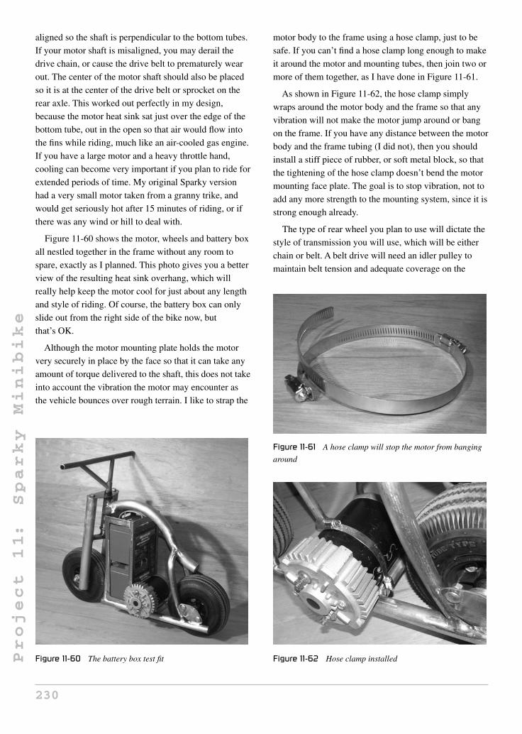
As shown in Figure 11-62, the hose clamp simply
wraps around the motor body and the frame so that any
vibration will not make the motor jump around or bang
on the frame. If you have any distance between the motor
body and the frame tubing (I did not), then you should
install a stiff piece of rubber, or soft metal block, so that
the tightening of the hose clamp doesn’t bend the motor
mounting face plate. The goal is to stop vibration, not to
add any more strength to the mounting system, since it is
strong enough already.
The type of rear wheel you plan to use will dictate the
style of transmission you will use, which will be either
chain or belt. A belt drive will need an idler pulley to
maintain belt tension and adequate coverage on the
Figure 11-61 A hose clamp will stop the motor from banging
around
Figure 11-62 Hose clamp installed
230

Project
11:
Sparky
Minibike
motor side pulley. A chain drive may or may not need an
idler sprocket, depending on your ability to either move
the rear wheel back and forth, or simply find the correct
length chain. Before you choose a transmission type, if
you haven’t done so already, let me explain the pros and
cons of both chain and belt drive transmissions.
Chain drive
Chain drive is by far the most common method of
transmission for motorcycles and scooters, which is why
90 percent of the small wheels you can purchase will
have a sprocket mounting flange or a sprocket already
installed. Chain drive is considered more efficient than
belt drive for the most part, and as long as your chain is
not extremely loose, you will probably not need an idler
sprocket to pick up the slack. You could even file the
motor mounting plate holes into more of a slot shape, so
that the motor can be moved back and forth about half an
inch to deal with the chain tension. Moving the motor or
the rear wheel is a very common way to adjust chain
tension, as you know from single-speed bicycles.
The main disadvantage of a chain drive is that it is very
dirty and extremely noisy. You will realize just how
noisy a chain drive can be if you listen to a store bought
electric scooter or pocket bike drive past you. The motor
is probably 99 percent silent, but that ratchety grinding
racket will make the vehicle sound almost as loud as a
similar sized gas-powered unit. It almost seems like a
disappointment to place a loud grinding transmission on
such a clean running, neighborhood friendly vehicle that
could be almost 100 percent silent, but the choice is
ultimately up to you.
Belt drive
As you can probably tell by now, I personally favor the
belt drive solution because it is absolutely silent, doesn’t
spit grease all over the place, needs no adjustment, and
can utilize parts found in an old washing machine or
dryer. It is said that belt drive is not as efficient as chain,
but to be honest, I have tried them both on the same
vehicle on more than one occasion, and noticed
absolutely no difference in top speed or overall range, so I
disagree based on my own personal experiences. Another
advantage of a belt drive is that it will take some of the
shock away from the motor if it is made to accelerate at a
dangerous rate, which is what could happen if you decide
to not use a motor controller and simply go for the
inexpensive contactor throttle. With a chain drive, there
is no slip, so you’d better hold on to your lug nuts if you
have a simple contactor and a powerful motor, because
you will accelerate with as much energy as your batteries
can deliver to the motor. With the motor I used, this
would result in a runaway motorcycle and a sore butt in a
real hurry. With a belt drive, there is some slip under
extreme load, and this slip is fully adjustable by adjusting
an idler pulley, so you can tailor the transmission for the
type of power and motor controller you plan to use.
In my design, I have a fairly tight belt for limited slip due
to the smooth ramping curve of my motor controller.
I can certainly do wheelies and burnouts if I like, but this
is by choice, not when I least expect it.
As shown in Figure 11-63, a belt or chain tensioner is
simply a flat pulley or sprocket attached to a rod that is
pressed into the belt or chain by a spring. The parts were
salvaged from a dead washing machine, but these flat
idler pulleys can be found at most hardware stores and
appliance repair shops. The idler pulley rides in the flat
side of the belt, so it does not have a typical V-groove on
its surface.
The idler pulley or sprocket (if necessary) will be
mounted to the motor mounting plate using a simple bolt,
as shown in Figure 11-64. Read ahead a few steps and
you will see how these parts come together in order to
form the idler system. Again, if you are using a chain,
you may not need an idler system, since you could simply
slot out the motor mounting holes to allow some degree
of chain adjustability. To make slots of the holes, just drill
Figure 11-63 Belt tensioner parts
231

Project
11:
Sparky
Minibike
Figure 11-64 Idler pulley mounting bolt
the same size holes directly beside the original holes, and
then use a small file to create the slot between them.
Figure 11-65 shows the idler pulley arm and pulley
mounting bolt which is made by cutting the head off a
bolt that will fit through the bearing of the idler pulley,
and then welding it to a small bit of flat bar or angle iron.
The size and position of this idler system depends on
your motor, mounting plate, and belt.
The idler pulley is fastened to the bolt installed in the
last step so that it looks like Figure 11-66. The pulley
should spin freely on its roller bearings, yet be securely
fastened to the arm so that it doesn’t rub on the arm.
The idler arm will be fastened to the bolt that is
welded to the motor mounting plate. By using a sleeve, it
can be positioned up or down, pushing the idler pulley
into the underside of the belt. As shown in Figure 11-67,
a small piece of tubing or a spacer that fits around the
bolt is welded to the other end of the idler arm. This is a
Figure 11-65 Idler pulley arm and pulley mounting bolt
Figure 11-66 Idler pulley installed
Figure 11-67 Idler arm mounting sleeve
similar idea to that used for the front wheel mounting
bolt and spacers.
As shown in Figure 11-68, the idler arm is free to pivot
around the bolt on the motor mounting plate, so that the
idler pulley can move up or down into the underside of
the drive belt. This will allow more of the belt to ride in
the small motor-mounted pulley, creating great friction
and less slip. The amount of controlled slip will be
determined by how hard the idler pulley is pushed up
into the belt.
Figure 11-68 Idler arm in position
232

Project
11:
Sparky
Minibike
To figure out what size of belt you will need, push the
idler pulley up about halfway, then run a measuring tape
around the outside lip of both pulleys, as shown in
Figure 11-69. This measurement will be close enough to
purchase the correct length belt, which will probably be
rounded to the nearest half inch. Notice the ratio of motor
pulley to wheel pulley (1:3). The 2-inch motor pulley and
6-inch wheel pulley gives us that magic 1:3 ratio for an
estimated top speed of 30 miles per hour and loads of
acceleration. If these were sprockets, they would be
about the same diameter, but would be rated in numbers
of teeth, rather than dimensions. A sprocket ratio of 15
teeth on the motor to 45 teeth on the wheel would be
about right.
The perfect length drive belt will enter and exit the
motor pulley at about the same angle, as shown in
Figure 11-70. This arrangement puts plenty of belt
around that small motor pulley, greatly increasing the
friction. If the system had no idler pulley, and the same
belt tension, there would be a large amount of slip due to
the fact that only a small percentage of the motor pulley
would have any belt in the groove. All we need now is a
spring to hold that idler in place.
Here is where you can do a little magic to tailor the
amount of maximum acceleration your transmission can
deliver. If you have a well-behaved motor controller with
a sensible acceleration ramp, then this idler spring can be
stretched out so that the pulley is quite tight against the
belt (it is difficult to push the idler pulley down by hand).
This spring is taken from an old mattress box spring, and
is quite difficult to pull apart by hand, although I can
Figure 11-69 Measuring the belt size
Figure 11-70 Test fitting the drive belt
muscle it in place with a pair of pliers. As you can see in
Figure 11-71, the spring is held under tension by a nut
welded to the fork leg so that the spring is pushing the
idler pulley into the drive belt. If you want to play around
with limited slip, then you could install a small plate with
multiple spring mounting holes, or simply use different
sized springs. Many washing machines, dryers and
furnaces use a system just like this, so keep that in mind
as you scavenge for parts.
Besides the connection from the batteries to the motor,
the rest of the bike is simple bits and pieces designed to
hold the accessories such as seat, lights, fenders, etc. Feel
free to go crazy on customization and additions here;
there is certainly no strict set of rules and guidelines
when it comes to these parts. Figure 11-72 shows the few
bits of 1/8-inch scrap flat bar I planned to use to create a
sturdy seat mounting platform just over the rear wheel.
I wanted a big phat seat placed directly over the rear
wheel as low as possible, so that the rider would sit low
and comfortable on the little hog with just enough knee
Figure 11-71 Idler tension spring
233

Project
11:
Sparky
Minibike
Figure 11-72 Seat mounting plates
room for the handlebars. Because of the well-behaved
motor controller I planned to install, combined with the
front heavy weight added by the batteries, the rider’s
weight would be near the rear of the bike, with minimal
risk of an unplanned wheelie. As shown in Figure 11-73,
I cut a bit more from the tail of the main spine tube and
installed the seat mounting plates, so that my large seat
would be securely held in place by four large
woodscrews.
I decided to install all the little stuff before wiring up
the motor controller, so the temptation to drive the
unfinished, unpainted mini bike would not get me this
time. I made fender mounting plates for the front and rear
and a headlight mounting tab from various bits of scrap
steel and flat bar. Shown in Figure 11-74 are the front
fender mounting plate and the headlight tab.
Fender style can really lend a lot to the overall
appearance and attitude of your project, so feel free to
use your imagination here. A very stylish and strong
fender can be made by cutting the sides and top from
some thin (1/32) sheet metal using a jigsaw, as shown in
Figure 11-73 Seat mounting plates installed
Figure 11-74 Let there be light
Figure 11-75. I simply traced a pot lid that was slightly
larger than the wheels to create the fender sides, then
gave them a little flair at the ends to look like those big
Harley fenders. These fenders will cover quite a bit of the
wheel, and will be strong enough to jump up and down
on if sitting on the ground.
There are no fancy tools or mystical black arts used in
my garage, buddy, just hard work, basic tools, and a lot
of junk! To form the nice round fenders, I just tack weld
the side pieces to the top strip, and bend the top strip
around the side pieces as I tack weld about every inch or
so, as shown in Figure 11-76. The resulting fender is
perfectly round, as if rolled by an expensive tool that I
don’t ever plan to own.
The resulting fender shown in Figure 11-77 is what
you get by rolling the top strip along the end pieces as
you tack weld. As you can imagine, fenders, fairings, and
many other shapes can be made using this simple yet
highly effective system.
Figure 11-75 Cutting the fender pieces
234

Project
11:
Sparky
Minibike
Figure 11-76 Roll and weld
Figure 11-77 Tack welded fender
Once tack welded together, the entire outside joint can
be welded and ground smooth in very little time to reveal
the perfectly smooth fender, as shown in the foreground
of Figure 11-78. After welding the entire joint, I rough
grind the welds with a coarse disc, and then take a
sanding disc to clean up the weld until it looks like it was
professionally made. Do not weld the inside of the fender
joint, or you will warp the fender, pulling the sides
together.
I had some 2-inch thick rigid packing foam in my
garage, so I thought it would make a perfect seat material
to give the seat a real phat look. As shown in
Figure 11-79, I first cut the 3/4 plywood to form the seat
base, and then traced the area on the foam to rough cut it
with a razor knife. This seat is about the same size and
shape as a granny trike seat, but feel free to build to suit
your style.
Figure 11-78 Weld and grind the edges
Figure 11-79 Phat seat requires phat foam
Figure 11-80 Foam trimmed and glued to the wood
Once I glued the seat foam to the base, I took the
grinder and traced around the edge of the wood to make
the foam follow the exact perimeter of the seat base. As
shown in Figure 11-80, the foam is exactly the same
shape as the seat, so it is now ready to be covered.
235

Project
11:
Sparky
Minibike
Figure 11-81 Upholstery work is an art
Figure 11-81 shows my “poor man’s” method for
upholstering a seat. I simply take the ultra high-quality
“pleather” and stretch it as hard as I can around the seat,
using as many staples as possible to hold it in place. If
you can muscle the material with enough force, you will
get almost all of those wrinkles to flatten out, reducing
the “Christmas present” look in your seat. A sewing
machine and proper seaming would be a much better
alternative, but I am afraid the Atomic Zombie garage
has no such equipment!
How many staples are enough? The real question is,
how many do you have? I stretch that material until my
face turns red, and then blast as many staples as I can
into the material to hold it in place. It is pretty amazing
how much you can force that material to conform to the
seat, even a seat with so many curves, like the one shown
in Figure 11-82. When you think you have enough
staples, add more.
Figure 11-82 I keep the staple company in business
Considering the crudeness of my upholstering
methods used, the seat shown in Figure 11-83 actually
looks pretty good! Once the material was stretched and
stapled, I tapped in some copper thumb tacks with a
hammer to give the seat a more authentic look. There are
only a few wrinkles near the base of the seat, but I
actually think they add to the look.
You now have a place to sit, but your feet need a place
to rest, so the foot pegs are next on the list of things to
do. The perfect foot pegs can be taken from a freestyle
BMX bike—these are light yet strong aluminum tubes
that bolt onto the rear axles so riders can stand on them
and pull stunts. To fasten them to our frame, simply weld
a bolt onto the front of the bottom tube and place the
pegs into the bolt. As shown in Figure 11-84, I used a 3/8
bolt and then drilled out the foot pegs to fit over this bolt.
Figure 11-83 Completed hog-style seat
Figure 11-84 Foot peg mounting bolts
236

Project
11:
Sparky
Minibike
Locknuts were then used. These foot pegs can be found
as accessories anywhere that sells bicycles and parts.
As shown in Figure 11-85, the foot pegs should be
installed onto the frame on a slight upwards angle, so that
they do not strike the ground when your mini bike leans
into the corners. Twenty-five degrees should be more
than enough angle to allow the mini bike to lean into
corners. Because the bike only has a few inches of
ground clearance, the foot pegs also work as a kickstand
if you simply let the bike rest on them.
The battery box was made to be easy to swap out or
remove for charging, so it is held to the frame using this
tab and nut system, as shown in Figure 11-86. A small bit
of flat bar, or even a washer with one side ground flat, is
welded to the battery box near the top and at the bottom,
so all you have to do is remove two bolts to pull the
battery pack out. The easiest way to get the nut in the
correct place over the hole is to install the bolt to the nut,
Figure 11-85 Foot pegs are installed to allow the bike to lean
in turns
Figure 11-86 Battery box mounting tab
and then tack weld it to the frame so it ends up in the
correct position.
Figure 11-87 shows the bolt holding the battery box
securely in place. There is another nut and tab just like
this one at the bottom of the battery pack so that it does
not rattle around under heavy vibration.
This is the last time during this project that I will
ramble on for more than a paragraph, since it is almost
time to paint and ride, but since it is time to install some
type of motor controller, like the one shown in
Figure 11-88, a little bit more information needs to be
given.
Simple contactor
The simplest and least expensive method of transferring
power from your battery pack to the motor is through a
simple switch called a “contactor,” which often looks
Figure 11-87 Battery box bolted onto the frame
Figure 11-88 The motor speed controller
237
Project
11:
Sparky
Minibike
like a large doorbell that will be mounted on the
handlebars so that you can press it with your thumb. This
is nothing more than a large-current-capable switch that
completes a circuit so that 100 percent of the available
horsepower is delivered instantly to the rear wheel.
Obviously, a powerful motor and large battery pack will
cause jerky, wheelie-prone take-offs, but this can be
reduced by using a drive belt with a bit less tension, or by
kicking off with one foot so that the bike is rolling a little
bit before the motor is engaged. To vary your speed,
simply toggle the contactor switch as needed. If you
would like to see the many available styles of contactors,
just do an Internet search for “ev contactor.” You will
need to choose a contactor that can handle your drive
motor’s “stall current,” or the battery pack’s maximum
discharge capacity, since this is the current that will flow
through the switch as your motor is asked to accelerate at
full capacity from a dead stop.
I have also made contactors from brass bolts, and by
installing cables into the solenoid plungers of automotive
starter solenoids, but unless you are certain of what you
are doing, this approach is not recommended because
you could create a contactor that may become stuck in
the on position. For the record, Sparky version 1 had a
simple contactor made by inserting a brass bolt through
the handle of a plastic brake lever, so that the bolt would
contact the metal handlebars closing the circuit. This
system did work quite well, but was prone to heating up
and always threw a huge spark when starting from a dead
stop, hence the name Sparky!
Motor speed controller
A motor controller is a far better approach for delivering
the battery current to the motor, because you will have
full control over the acceleration, top speed, and
sometime braking. Motor speed controllers send a
pulse-width modulated signal, varying in duty cycle from
zero to 100 percent to the motor at a high rate of
frequency, so that the motor acts as if you are varying the
current. If you had a simple contactor, you could pulse it
on and off to try to control your speed. However, the
motor speed controller has an onboard computer that
does this hundreds of times per second, so the speed
control is ultimately smooth. A throttle that has either a
lever or conventional twist grip is installed on the
handlebars, and the speed control is so fine that you can
make the wheel just barely turn, or rip up the ground
with rocket-like acceleration if your motor is capable of
doing so. A motor speed controller will also limit the
current to the motor, so you will not burn it out if you try
to push it too hard, and the acceleration will follow some
type of ramp, so an accidental wheelie will not occur if
you open that throttle too far from a dead stop.
The downside of a real motor speed controller is of
course the price. I highly recommend that you give this
option some real consideration, as it will make your
riding experience so much more enjoyable, and allow
you to keep your machine under complete control,
especially in a crowded area where you need precise
control of your vehicle. You can also limit the top speed
for younger riders, and lock the mini bike when not in
use, by adding a key switch if it is not already part of the
controller kit. Choosing a controller is much like
choosing a simple contactor; you must choose a
controller that will handle the rated capacity of your
motor at the chosen voltage. Most motor speed
controllers do have current limiting, so choosing a lower
current controller than required will usually only result in
poor performance, but there is a limit, and if your
controller is too “wimpy,” it will burn out on hills or even
when you ride against the wind for too long.
My motor controller is an Alltrax golf cart unit rated
for 275 amps continuous, and 400 amps peak for 30
seconds. What this means is that when I am starting
from a dead stop, the motor will get 400 amps if my
battery pack can deliver it (unlikely), and then the
controller will be happy delivering 275 amps to the
motor all day or until the batteries give it up. This
controller is actually overpowered for my motor and
batteries, but I know that there is virtually nothing I can
do to blow the controller, and it will climb hills, spin dirt,
and outperform most store-bought scooters all day
without even getting warm.
When you do a search for “ev parts,” or “motor
speed controllers,” you will find a lot of great
information, and there are many different products
available to choose from. Like all parts, try to find a
reputable company, and ask them for advice when
choosing a controller. You really want to avoid an
underrated controller for your motor, and if your budget
allows, purchase the next step up just to be safe. I plan to
build many different electric vehicles with this motor and
238

Project
11:
Sparky
Minibike
controller, so I am confident it will hold up to whatever
abuse I throw at it.
Regenerative braking
For typical riding, most of my braking comes from the
resistance that the controller puts across the motors
terminals when I release the throttle. What is happening
is that the motor is no longer receiving current; it is being
forced to generate it, which puts a load on the motor,
effectively slowing it down. If your controller has
full-blown regenerative braking (regen), then you will
not only get a large amount of smooth, throttle-controlled
braking ability, but your batteries will get a little bit of
charging as the controller pumps current from the motor
back to the batteries. In a large vehicle, this can
significantly increase the run time, but in a vehicle like
Sparky, this is just an added bonus, especially on a
design like mine with no built-in wheel brakes.
Obviously, if your controller has no regen, then you’d
better have at least one decent wheel brake for safety.
Depending on the level of regen your controller has,
wheel brakes may not even be necessary, although a bad
controller failure could also deplete all your braking
ability. A simple motor pulley brake will be presented
later as well, just in case you are limited by the wheels
and the motor speed controller.
I decided to complete the frame by capping off the
extra tubing left over when I cut the bottom tubes rather
than cutting them off. I inserted a pair of chrome lug nuts
into the ends of the tubes and welded them in place, as
shown in Figure 11-89. After painting, I brushed off the
paint at the tips of the lug nuts with some steel wool.
These small details make a huge difference, if you plan
to sit in one place long enough to show off your custom
creation. Take this opportunity to check over all the
welds, and clean up any rough spots and holes.
Apply a good metal primer after cleaning up the parts
with some fine sandpaper. I know it’s torture to wait for
primer and paint to dry, but if you follow the instructions
and do it right, then a simple spray-can job can look just
as good as a professional job. I normally prime the parts
then let them sit for a day, and then do the spray painting.
The spray paint should be left for a few days to cure
before you assemble the bike, although I will admit that
sometimes my impatience gets the best of me. Fresh
Figure 11-89 Capping the tubing ends with chrome lug nuts
paint is easy to scratch and chip for at least a week after it
dries, so be careful. Figure 11-90 shows the freshly
primed parts taunting me to work faster.
Figure 11-91 shows a fresh-looking, bright orange
Sparky assembled again after the paint has cured for a
week (I seriously did wait a week). The simple orange
with black accents actually turned out quite well, and the
little mini bike was starting to resemble a little hog as
planned.
Figure 11-92 shows Sparky with all the major
components installed, waiting to have the wiring done.
Take your time and solder all wires using the proper
clips, following the wiring diagram that came with your
motor controller. Do not get lazy and leave out the
recommended fuses and safety switches just in case you
have a crossed wire, or the only smoke show you will be
Figure 11-90 Frame parts primed
239

Project
11:
Sparky
Minibike
Figure 11-91 Shiny and new!
Figure 11-92 Waiting for a wiring job
creating is one where all the Metal Oxide Silicon Field
Effect Transistors (MOSFETs) in your controller
explode. There is no standard wiring diagram I can show
you since each motor controller and contactor will have
its own wiring map, but I can tell you that you have a
50 percent chance of hooking up your motor in reverse!
Most of these small DC motors, mine included, have no
polarity and rotation shown on the terminals, so you may
end up hitting that throttle and going in reverse. This will
not cause any damage, but your first attempt at spinning
the drive wheel should be done on blocks before your
first test ride.
Most of the wheels available for small scooters and
mini bikes will have some type of brake already built
into the wheel in the form of drum brakes or band
brakes. It is a matter of installing a bicycle brake lever as
shown in the manufacturer’s instructions, in order to
have brakes on one or both wheels. My wheels did not
offer any simple method of adding a brake, but since my
motor controller had a decent level of braking by simply
letting off the throttle, I did not bother trying to install
any other brakes. If I had a simple contactor rather than a
motor controller, I would certainly need some type of
brake, so I devised the system shown in Figure 11-93, in
case you have brakeless wheels and a simple contactor.
The brake is just a bicycle pull brake with the pads
turned sideways so that they grab hold of the aluminum
drive pulley when I engage the brake lever. It may not
look like much, but remember that the gear ratio between
the motor pulley and the wheel pulley is 1:3, so this
brake is effectively grabbing a wheel of 6 inches in
diameter. Using only this brake to stop, I can bring the
mini bike to a dead stop from full speed in a distance of
about 20 feet, which is not too bad.
If you take a sharp knife and cut the brake pads to
conform more to the pulley body, then the braking
power will be increased even more. Some production
scooters and pocket bikes use the same system as this for
brakes.
After looking at so many photos of this mini bike
being built, you may have forgotten how small Sparky
really is! Figure 11-94 brings this into perspective,
showing how little real estate he really occupies. Many
onlookers chuckle as I unload Sparky from the back of
Figure 11-93 A sneaky brake, in case you find it necessary
240

Project
11:
Sparky
Minibike
Figure 11-94 Yo, look at my bad-ass hog!
the truck, but their smirks usually turn to slack jaws as I
vanish out of sight at speeds normally accomplished by
street motorcycles. It’s also fun to creep up on a person
from behind, and then zip past them since Sparky is
virtually silent. The only sounds you usually hear are the
sounds that the tires make on the ground and my evil
laugh. I can actually sneak up on those Canadian geese
shown in the background, but let me assure you, just
because you can do something does not make it a good
idea! Some people (and geese) don’t always appreciate
your stealthy electric vehicle!
With the way Sparky is styled, it almost looks like
Figure 11-95 has been manipulated somehow to make
me look like a giant. It’s hard to believe that Sparky can
keep up to city traffic, run for well over an hour and
completely out-accelerate store-bought scooters or
pocket bikes, even the gas ones. Trust me, this little dude
has attitude and power!
Figure 11-95 Look, that dude is 15-feet tall!
The nice thing about a motor controller, as compared
to a simple contactor, is that younger riders can enjoy the
ride as well. Your motor controller can even be strictly
controlled by placing a ring on the handlebars that would
prevent the throttle lever from engaging to the maximum.
If you know a bit about electronics, you could also add a
series resistor between the throttle and the motor
controller to limit the top speed, by reducing the ability
of the throttle’s variable resistor to reach the maximum
resistance. If you have only a simple contactor, the belt
idler spring could be relaxed a bit to limit the overall
acceleration, although the mini bike would still
eventually reach top speed. Figure 11-96 shows one of
our test pilots, Brittany, putting Sparky through its paces
over three hours one afternoon.
It doesn’t take very long before you get up the
courage to want to push Sparky to the limit! With all
that power available, you can shoot up any hill, blast
Figure 11-96 Sparky is well behaved
Figure 11-97 Silent, fast, and fun
241

Project
12:
LongRanger
Scooter
Figure 11-98 Still going strong after hours of vigorous riding
up the dirt, pull wheelies, and even give a buddy a
ride, although sitting on the frame tubing sure does
hurt!
With all that vigorous riding, Sparky may wear you
out before the batteries need a recharge, but when the
time comes to plug in, you can expect to be back on the
trails within 4 to 6 hours, depending on the size of your
battery pack and speed of your charger. If you can’t get
enough, just have two battery packs so you can cycle
them for non-stop fun. Oh, and when you finish your
custom electric mini bike, do remember to send us a
photo for our gallery, as we love to see what other garage
hackers are building!
Project 12: LongRanger Scooter
The LongRanger fills a gap between the
electric-motor-assisted mountain bicycle and the fully
street-legal electric motorcycle or scooter, allowing you
to commute great distances at speeds typical of a standard
human-powered bicycle. Because the LongRanger looks
and feels much like a standard mountain bike, it will
happily live on bike paths and trails normally off-limits
to larger motorized vehicles. The LongRanger can be
made to travel well over 62 miles (100 kilometers) on a
single charge, and will do so at speeds that only a top
athlete could keep up for any real distance. Oh, and it
does all this without making any pollution or noise
whatsoever! Because the LongRanger is built around the
battery pack and the type of hub motor you choose, you
can build the base vehicle to suit your needs, altering the
top speed, acceleration, weight or range.
It’s a good idea to read over the entire plan once before
hacking up any bikes or heading to the scrapyard on a
search for parts. By reading ahead, you will see why a
certain part was chosen, and get some ideas on how to
modify the design to suit your needs. With even a slight
change in a few of the main frame tubes, you could make
a completely different looking chopper, even though the
core design has been followed. Don’t be afraid to try new
things, and remember that hard work is what makes this
hobby successful, not spending money on
mass-produced products. Long live the real custom!
Regardless of the size and number of batteries you
plan to install, you will need a front wheel, suspension
fork, and matching head tube from a sturdy mountain
bike. To ensure that all the parts fit together properly, it is
recommend that you salvage these parts from the same
bike, preferably one in decent condition. I actually
purchased a brand new mountain bike on sale at the
hardware store, and then stripped all of the parts off,
leaving what you see in Figure 12-1.
Often, you can purchase a decent quality,
full-suspension mountain bike on sale for a hundred
bucks, which is not bad considering you end up with a
new aluminum front wheel, tire, suspension system,
frame, and one rear shock. I know, the quality of an
242Copyright © 2008 by The McGraw-Hill Companies, Inc. Click here for terms of use.

Project
12:
LongRanger
Scooter
Figure 12-1 Choosing a front wheel and suspension fork
inexpensive department store bike is nowhere near that
of a high-end mountain bike purchased from a quality
dealer, but at least all the parts are new, and the frame is
made of steel, so it can be welded. I ended up using the
rear of the bike to make a tadpole trike called the
StreetFox, so a hundred bucks was actually a great deal.
Regardless of where you acquire the parts, you will
need what is shown in Figure 12-1—a front wheel and
suspension fork, a matching head tube with at least a
small portion of the frame tubing still intact, two similar
rear shocks, and the front brake hardware. Don’t worry
about the rear triangle of the frame, as it will not be
needed.
As you can see in Figure 12-2, the entire front of the
mountain bike will be used, which is why it is optimal to
work with parts that fit properly together and are in good
working order. Stand up the frame with the front tire
fully inflated so that the head tube is at the angle it was
when the bike was complete, or at an angle typical of a
standard bicycle, which is usually somewhere between
Figure 12-2 Using a guide bar to make a straight cut
72 and 74 degrees. If your donor frame does not include
rear hardware or a rear wheel, like my frame shown in
Figure 12-2, you will have to figure out a way to stand up
the frame so that the head tube is at the correct angle,
since the cutting line is derived this way. As you can see
in Figure 12-2, I have placed the rear of the frame on a
plastic bucket and a bit of scrap wood, so that the head
tube is at roughly the same angle it would have been if
the entire bike were still together.
Head tube angle is measured by extending an
imaginary line to the ground and then taking the angle of
this line with that of the horizontal ground. Rather than
messing around this way, simply roll a functional bicycle
up next to your supported frame and match up the angles
as closely as you can. A few degrees either way is not
going to make a huge difference in the completed
vehicle. The angle of my head tube, as shown in
Figure 12-2, was determined by placing another
mountain bike alongside the donor frame for reference,
as I propped up the rear of the frame. My head tube angle
is approximately 73 degrees.
Also shown in Figure 12-2 is a length of flat bar placed
vertically, 4 inches back from the edge of the front tire.
This flat bar is used as a guide to mark a line on the top
tube and down tube for cutting. Since the battery box will
be a perfectly square box riding parallel to the ground,
the frame cut lines are to be marked so they are 90
degrees to the ground. To do this, either have a helper use
a 90-degree square to check the angle of your guide bar
with the ground, or use a level to check this angle as you
hold the guide bar against the frame.
Figure 12-3 shows the frame tubing marked for cutting
after ensuring that the guide bar was placed 4 inches
behind the edge of the front tire, and at 90 degrees to the
ground so it was perfectly vertical. A black marker is
used to mark the line, which needs to be the same on
both sides of the frame.
Once the cut lines have been clearly marked on both
frame tubes, use a hacksaw or cut-off wheel in your
grinder to cut away the front of the frame from the rest of
the frame. I use a cut-off disc (zip disc) for all my metal
cutting because it’s much faster and more accurate than a
hacksaw, but do be careful when hacking up
bicycle frames. On the first cut through a complete frame
tube, the frame may start to collapse on the grinder disc if
under tension, so keep this in mind as you complete any
cuts, holding on to the grinder with both hands. To avoid
243

Project
12:
LongRanger
Scooter
Figure 12-3 Marking the frame for cutting
this, the last half inch of the cut can be made with a
hacksaw to avoid any disc snagging that might occur.
Figure 12-4 shows the front of the frame, including a
head tube and a few inches of top tube and down tube.
To aid welding and avoid filling the garage with horrific,
burning paint fumes, the paint was removed around the
joint ahead of time using some sandpaper. A sanding
disc (flap disc) is also an easy way to remove paint
easily.
Although we will discuss the hub motor, controller and
batteries in greater detail later, you will need to know the
dimensions of the batteries you plan to install on your
version of the LongRanger, in order to continue building
the frame. If you have not decided on a brand or type of
hub motor and batteries yet, then read ahead so you can
see how these components will affect the range, weight,
and speed of your final design. The obvious goal of the
LongRanger is of course long range, so batteries much
larger than those considered typical of an
Figure 12-4 The front of the frame has been cut
electric-assisted bicycle will be used. As you will soon
see, the frame is actually built around the batteries, since
they are the key element in the entire design.
Figure 12-5 shows the huge size difference between
the standard, hub motor kit batteries and the ones I plan
to install in the LongRanger. The small batteries are rated
at 7 amp hours each, and the larger ones are rated at 32
amp hours each, so the expected range of the larger
batteries is about four and a half times more. The small
batteries measure 6" by 2.5" by 4", and the large ones
measure 7.75" by 5" by 7". Let’s discuss battery size
versus expected range.
There are many types of battery chemistries, and each
has certain advantages depending on the intended use.
Let me make this choice very simple—you should only
use sealed lead acid (GEL) batteries for this project.
Unlike a typical automotive lead acid battery, a sealed or
GEL battery does not have free-flowing liquid, nor does
it need maintenance such as “topping up” the fluids, so
there is no chance of spilling any corrosive liquid on
your vehicle or yourself. Sealed batteries are often
labeled as wheelchair or recreational batteries, and the
obvious sign that they are sealed is the lack of any type
of filling or maintenance valve on the top of the battery.
Sealed batteries may cost a little more than the
equivalent size wet-cell battery, but the extra cost is
worth it in terms of safety and overall battery quality.
The real question is: how far do you want to travel on
a single battery charge? Sure, you could go to the battery
store and tell them to give you three of the largest GEL
batteries they have, but do you really need to commute
half way across the country? Also, the larger batteries
can get very large and heavy, so you may be very
Figure 12-5 Comparing battery sizes
244

Project
12:
LongRanger
Scooter
uncomfortable straddling a 12-inch-wide battery box.
The batteries shown in Figure 12-5 have never needed a
recharge, even after two days of lengthy riding, so as a
guide, 32-amp-hour batteries will be more than enough
for any single journey you may want to undertake. There
are many sizes of GEL batteries in the smaller (under 40
amp hours) range, so your best bet is to look at the
estimated range of your hub motor kit with its current
batteries and work from there. If the original
10-amp-hour battery pack claims 25 miles (approx. 40
kilometers), then it is a safe guess that a 30-amp-hour
battery pack should deliver 120 kilometers of range. Of
course, I would divide any manufacturer’s range claim
by 1.5, as they have been known to exaggerate!
OK, let’s sum up all this battery talk. Only purchase
GEL batteries, and make sure all of them are the same
size and age. A battery larger than 35 amp hours is
probably too large, and anything less than 20 amp hours
might be too small. Use your original battery’s capacity
and range as a guide, but take manufacturers’ claims with
a grain of salt!
Figure 12-6 shows a stack of three GEL batteries
separated by blocks of wood so that the connecting
terminals do not rub on the underside of the battery
above. This battery pack will deliver 36 volts at 32 amp
Figure 12-6 The mighty 36-volt stack
hours. Voltage is the sum of all batteries in series, so
3 × 12 volts equals 36 volts. Amp hour rating is the same
rating as a single battery in a series connected pack, so
since each of these batteries is 32 amp hours, that is the
overall amp-hour rating of the pack. Why three batteries?
Simple—because the original pack was three batteries
and I did not want to overpower the hub motor, or have
to search for a different voltage charger. If you add an
extra battery to create a 48-volt pack, your hub motor
may have no problem with the higher voltage, and it will
actually run a bit faster, although you will now have to
source a 48-volt battery charger, and make room for one
extra battery. Unlike a higher amp-hour rating, with more
voltage, range will not increase.
Unless you know what you are doing with batteries,
controllers and chargers, the best bet is to simply
increase the amp-hour rating of your batteries, and use
the same number of batteries and charger that came with
the original kit. My charger is only rated for a 1-amp
charging rate, which is very small, but it takes care of the
32-amp-hour pack overnight if I do not run it down too
far. The typical 36-volt charger is between 2 and 4 amps,
so you will be fine.
As shown in Figure 12-6, you must stack up your
batteries in such a way that the connection terminals do
not rub on the underside of the above battery. Some small
pieces of 2 × 4 wood seem to do the job perfectly. Solid
rubber hockey pucks may also be a good choice if you
have access to them.
Once you have your batteries stacked up and insulated
from each other, you can begin making the battery pack
rails by using the actual stack of batteries as a guide. As
shown in Figure 12-7, four lengths of 1/16-inch thick,
1-inch-wide angle iron have been cut and strapped to the
battery pack using an elastic cord. These four lengths of
angle iron will form the side rails of the battery pack, and
should reach from the base of the lower battery to 1 inch
above the top of the upper battery terminal.
Be careful when handling the metal bars around the
batteries, especially if the battery terminals are not
insulated with a plastic cover. Dropping the metal across
the battery terminal will not only cause an extremely
loud and startling spark, it could damage the battery or
cause a nasty burn. You can safely come in contact with
the terminals because the voltage is much too low to
deliver a shock, but there is certainly enough amperage
there to weld steel!
245

Project
12:
LongRanger
Scooter Figure 12-7 Battery pack side rails
You should place a few strips of cardboard or thick
paper between the angle iron and the batteries for extra
clearance, so the batteries are not extremely tight, and
this way they can be replaced easily.
The battery pack base is also made by cutting four
pieces of the same angle iron in order to form a box, as
shown in Figure 12-8. Although I test fit the base on the
top of the pack, the measurements will be the same since
the rails are the same all the way along the battery pack.
The two longer pieces will overlap, as shown in
Figure 12-8, and this is not a problem since the ends will
all be cut at 45 degrees to form a square.
Figure 12-8 Cutting the battery pack base
To make a perfectly square base of the angle iron, each
corner needs to be cut at 45 degrees, as shown in
Figure 12-9. Mark the ends using a black marker and a
45-degree square by drawing a line from the end corner
where the two sides of the angle iron meet. A hacksaw or
zip disc is then used to cut off the corners.
Figure 12-10 shows the battery pack base tack welded
together for a test fit over the side rails. Make sure the
base is square and can slide over the four side rails
without forcing them to squeeze the side of the battery.
The idea is to make a pack that holds the batteries
snuggly, but not so much that you can’t slide them in and
out of the rails if they need to be removed for whatever
reason. If the base seems to be square and fits the rails
correctly, weld all four joints on the outside of the box
(the side showing in Figure 12-10). The inside of the box
is not welded because it would create a raised spot under
the batteries, adding stress to the underside of the
lower battery, which must carry the weight of all three
batteries.
The side rails drop in to the base, as shown in
Figure 12-11, and should allow the battery to slide right
in with minimal friction. Remove the batteries when tack
welding the corner of the joint to avoid burning the thin
Figure 12-9 Making the square battery pack base
Figure 12-10 Tack welded battery pack base
246

Project
12:
LongRanger
Scooter
Figure 12-11 Installing the side rails
plastic casing of the battery. At this point, only tack weld
the side rails in place; this way, the entire box can be
squared up once the top has been added.
The top of the battery box is made from 1-inch flat bar,
or by cutting a length of angle iron into two pieces by
cutting it along the bend. Since the batteries need some
way in and out of the battery pack, angle iron could not
be used to make the top of the box as it would seal the
opening. The top four bars shown in Figure 12-12 are cut
so they form a box of exactly the same dimensions as the
box on the base of the battery pack. Only tack weld the
bars in a few places so you can square up the entire
battery pack by forcing it into shape. This is a good time
to test fit a battery to make sure it slides into the pack
without much resistance.
Figure 12-12 Adding the top bars
Once you have your battery pack tack welded together
and squared up, you can finish welding all the outer
joints to complete the pack. The completed battery pack
is shown in Figure 12-13, with all the outer joints fully
welded to give great strength to the box. None of the
inside joints are welded because this would make it
difficult to insert the batteries, and is not necessary for
strength. You’d better test fit all three batteries one last
time to ensure that heat distortion did not pull the box out
of square.
The LongRanger is a battery box with wheels! On a
regular diamond frame bicycle, there is little possibility
of carrying 60 pounds of large batteries on the frame
without dangerously overloading the frame or upsetting
the balance. On the LongRanger, carrying the batteries
is the purpose of the frame, so the most important part of
the frame is a battery box holder. This part of the frame is
called the center frame, and it is simply a square frame
around the battery pack made of 1.5-inch steel tuning
with a wall thickness of 1/16 inch. The four pieces are
shown in Figure 12-14.
This tubing can be ordered from any steel supplier, and
is very easy to cut and weld. Steel suppliers like to rate
tubing wall thickness using a gauge number, so 1/16 wall
tubing will be called 16-gauge tubing, and although there
is a slight difference between the two, your best bet is to
tell them you want a length of 1.5-inch square tubing
with a wall thickness as close to .0625 of an inch (1/16)
as you can get. If you are a heavy rider (over 300
pounds), then you should ask for the next size after that,
which will most likely be 14-gauge tubing, or .078-inch
wall tubing.
Figure 12-13 Battery pack welding completed
247

Project
12:
LongRanger
Scooter
Figure 12-14 Tubing for the center frame
How much tubing you will need is completely
dependent on the perimeter of your newly created battery
pack. Simply measure the perimeter of the battery pack
around its longest dimension and then add a few inches
to spare when you source your tubing. The rear
swingarm will also be made from the same tubing, so add
3 feet to the battery box perimeter and you will easily
have more than enough tubing.
To make a perimeter frame around the battery pack,
you need to create a frame out of the 1.5-inch tubing that
will have the same inside perimeter as the outside of the
battery pack. Add a quarter inch to the perimeter of the
center frame, so the battery pack can have a little room to
slide in and out of the main frame. With this design, you
can have more than one battery pack for quick change if
you do not want to wait overnight to charge the pack.
This design also makes it very easy to remove the entire
battery pack for use on another vehicle or for
maintenance if needed. Figure 12-15 shows the four
lengths of 1.5-inch square tubing cut at 45-degree angles,
Figure 12-15 Cutting the center frame tubes
so that the resulting frame has an inside dimension
approximately a quarter inch larger than that of the
battery pack. The battery pack can drop right into the
center frame.
Using a 90-degree square, set up the center frame on a
flat surface and then tack weld the four corners together,
as shown in Figure 12-16. With a tack weld on each
corner, recheck the alignment with the square and adjust
if necessary. The frame will be easy to manipulate into
shape with only a single tack weld at each corner.
When you are satisfied with the alignment, check one last
time by dropping the battery pack into the frame, and
then add a few more tack welds around the frame to keep
it from moving.
When you have checked the center frame alignment
using a 90-degree square and you are certain that the
battery pack will fit inside, fully weld each outer corner
joint, and then check the alignment one last time. The
final welding is done on each side of the 45-degree angle
joints to complete the center frame welding, as shown in
Figure 12-17.
Welding the inside joint of the center frame should be
done using the smallest weld bead you can possibly
make, in order to avoid warping the frame or creating a
high spot that will interfere with the installation of the
battery pack. Figure 12-18 shows the small weld bead
Figure 12-16 Squaring up the center frame
Figure 12-17 Center frame welding completed
248
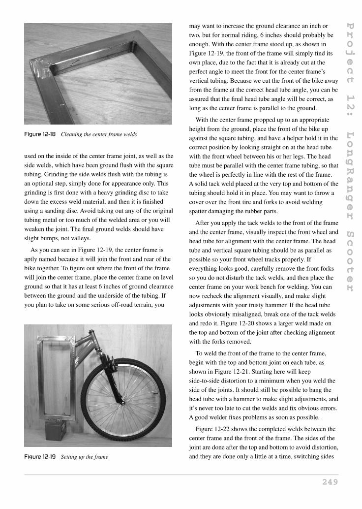
Project
12:
LongRanger
Scooter
Figure 12-18 Cleaning the center frame welds
used on the inside of the center frame joint, as well as the
side welds, which have been ground flush with the square
tubing. Grinding the side welds flush with the tubing is
an optional step, simply done for appearance only. This
grinding is first done with a heavy grinding disc to take
down the excess weld material, and then it is finished
using a sanding disc. Avoid taking out any of the original
tubing metal or too much of the welded area or you will
weaken the joint. The final ground welds should have
slight bumps, not valleys.
As you can see in Figure 12-19, the center frame is
aptly named because it will join the front and rear of the
bike together. To figure out where the front of the frame
will join the center frame, place the center frame on level
ground so that it has at least 6 inches of ground clearance
between the ground and the underside of the tubing. If
you plan to take on some serious off-road terrain, you
Figure 12-19 Setting up the frame
may want to increase the ground clearance an inch or
two, but for normal riding, 6 inches should probably be
enough. With the center frame stood up, as shown in
Figure 12-19, the front of the frame will simply find its
own place, due to the fact that it is already cut at the
perfect angle to meet the front for the center frame’s
vertical tubing. Because we cut the front of the bike away
from the frame at the correct head tube angle, you can be
assured that the final head tube angle will be correct, as
long as the center frame is parallel to the ground.
With the center frame propped up to an appropriate
height from the ground, place the front of the bike up
against the square tubing, and have a helper hold it in the
correct position by looking straight on at the head tube
with the front wheel between his or her legs. The head
tube must be parallel with the center frame tubing, so that
the wheel is perfectly in line with the rest of the frame.
A solid tack weld placed at the very top and bottom of the
tubing should hold it in place. You may want to throw a
cover over the front tire and forks to avoid welding
spatter damaging the rubber parts.
After you apply the tack welds to the front of the frame
and the center frame, visually inspect the front wheel and
head tube for alignment with the center frame. The head
tube and vertical square tubing should be as parallel as
possible so your front wheel tracks properly. If
everything looks good, carefully remove the front forks
so you do not disturb the tack welds, and then place the
center frame on your work bench for welding. You can
now recheck the alignment visually, and make slight
adjustments with your trusty hammer. If the head tube
looks obviously misaligned, break one of the tack welds
and redo it. Figure 12-20 shows a larger weld made on
the top and bottom of the joint after checking alignment
with the forks removed.
To weld the front of the frame to the center frame,
begin with the top and bottom joint on each tube, as
shown in Figure 12-21. Starting here will keep
side-to-side distortion to a minimum when you weld the
side of the joints. It should still be possible to bang the
head tube with a hammer to make slight adjustments, and
it’s never too late to cut the welds and fix obvious errors.
A good welder fixes problems as soon as possible.
Figure 12-22 shows the completed welds between the
center frame and the front of the frame. The sides of the
joint are done after the top and bottom to avoid distortion,
and they are done only a little at a time, switching sides
249

Project
12:
LongRanger
Scooter
Figure 12-20 Head tube welded to the center frame
Figure 12-21 Weld the top and bottom first
after an inch-long weld. The head tube should remain in
good alignment using this welding technique, and this
can be checked by reinserting the front forks and wheel
for a final visual inspection. This weld should only be
cleaned by removing spatter or bumps, but do not grind
the weld metal or it may weaken the joint.
Until a few years ago, the most common way to add
clean motive power to a small vehicle, such as a moped,
Figure 12-22 Front frame completely welded
scooter, or bicycle, was to drop in a chain, belt, or
friction-driven electric motor. This system was OK, but
due to the minimal availability of quality small motors,
often the resulting drive system was inefficient, noisy,
and lacked proper speed control. You could spend a
larger amount of money to get a quality motor speed
controller, a more efficient motor, and larger batteries,
but by the time you add all these costs together, the final
price tag could easily be $1,500 or more, and the motor
may be a little on the large side for a bicycle-type project.
There have been numerous, inexpensive, electric add-on
kits for bicycles popping up on the market, but often they
are inefficient and cheaply made, with barely enough
power to get you over a slight hill or moving into a
headwind, and range is often a serious problem. Enter the
hub motor!
What type of hub motor should you purchase?
Obviously, there are hundreds of them on the market now
with prices varying from approximately $200 to over
$1,000. Like all products, you usually get what you pay
for, but there are several factors that will influence the
price of a hub motor kit, such as internal construction,
output power, rim quality, and the type of batteries and
charger that come with the unit. My hub motor, shown in
Figure 12-23, is a 450-watt brushless unit built into a
20-inch wheel. It comes with the twist throttle, controller,
charger, wiring, and the batteries shown in Figure 12-5.
The price on my hub motor kit is approximately $500,
and is considered to be a higher quality unit due to the
brushless construction. A brushless hub motor has no
wear parts, and will never require maintenance, whereas
a brushed motor will require changing the internal
brushes about once a year if well used. Brushless motors
250

Project
12:
LongRanger
Scooter
Figure 12-23 A complete hub motor kit
are also more efficient, so if you can afford the extra cost,
choose a brushless design.
As for motor power, there will be plenty of data on the
manufacturer’s website regarding speed and range.
Again, range is usually inflated, but often top speed is
rated very accurately. Due to top speed regulations,
almost all hub motors will top out around 22 mph (35
km/h), which is dependent on the rim size. A smaller rim
will slightly reduce your top speed, but will increase your
hill climbing ability. For this reason, my LongRanger has
been fitted with a 20-inch rim to allow better hill
climbing power and off-road use. My top speed peaks at
around 17 mph (28 km/h). The wattage rating of the hub
motor is what will determine the amount of hill climbing
power and acceleration you can expect, with 450 watts
being at the lower end of the scale and 1000 watts at the
upper end of the scale. My 450-watt motor can climb a
fairly steep hill, and take on any headwind, but I also
have the added torque due to the smaller 20-inch wheel.
As a general guide, shoot for a 450–550-watt motor for a
20-inch wheel, and a 600–750-watt motor for a 26-inch
wheel. If you really want serious acceleration and hill
flattening power, a motor of 750 watts or more will be
extreme, although at the cost of reduced range.
My recommendation is to try a bicycle fitted with a
hub motor kit, and see how it runs without any pedaling
input. You can really tailor the power characteristic of the
LongRanger from “running all day long at bicycle
speeds” to “taking off like a rocket and pulling wheelies,”
depending on your motor choice. And as always, a deal
that looks too good to be true almost always is. Avoid the
junk and you will have a quality electric vehicle.
The rear wheel on the LongRanger is actually a front
hub motor, since there are no sprockets on the bike. The
rear wheel will be placed behind the center frame at the
same 4-inch distance from the rear tube as the front wheel
is away from the front tube. It does not matter if you have
a 20-inch or 26-inch rear wheel, as the same clearance is
needed. Figure 12-24 shows the placement of the rear
wheel as the bike is positioned level to the ground.
The rear suspension swingarm is made from the same
1.5-inch square tubing as the center frame, which is why
I stated that you should have a few feet extra. The two
longer tubes are cut to a length appropriate for the chosen
rear wheel and tire size, and the small tube is cut to a
standard front hub length. The three tubes are shown cut
in Figure 12-25, based on the drawing in the next figure.
If you are using a front hub motor (one without a
sprocket), then it will fit on a standard front bicycle fork,
Figure 12-24 Positioning the rear wheel
Figure 12-25 Cutting the swingarm tubing
251

Project
12:
LongRanger
Scooter
which has dropouts placed 4 inches apart. For this
reason, the smaller swingarm tube that joins the two
longer tubes is cut to a length of 7 inches using 45-degree
cuts at each end, so its inner width is 4 inches, as shown
in Figure 12-26. The two longer tubes are cut to a length
that is equal to the distance from the axle of the wheel to
the edge of the tire, plus 1.5 inches for the width of the
smaller tube and 1.5 inches for tire clearance. For this
reason, you need to have the tire you plan to use installed
on the rim and fully inflated when you make these
measurements. The length of my two longer swingarm
tubes (for my 20-inch wheel) was 11.5 inches, but I
recommend that you get this measurement based on your
rim and tire. If you are planning on using a massive rear
tire, such as a 16-inch motorcycle tire mounted to a
20-inch bicycle rim (yes, this works), then the swingarm
may need to be wider than the standard 7 inches.
With the measurements derived from Figure 12-26, the
three swingarm tubes are cut, as shown in Figure 12-27.
Figure 12-26 Swingarm clearance
Figure 12-27 Tack welding the swingarm tubes
The small tube has a 45-degree cut at both ends, and the
longer tubes have a 45-degree cut at only one end. Place
the three tubes on a flat surface and use a bit of scrap
steel to keep the open ends in place as you tack weld the
assembly together. As shown in Figure 12-27, the 4-inch
inside width is held by the smaller swingarm tube and the
bit of scrap angle iron welded across the open end. Once
tack welded, pick up the swingarm and visually inspect it
for alignment. Both legs should be perfectly parallel to
each other, and the ends should be square.
With the swingarm tack welded and checked for
alignment, you can complete the welding by starting with
the outer corner welds and then the top and bottom
welds. The inside of the joint welding is done last, and
with a small bead to minimize the inward pulling of the
swingarm legs from head distortion. Clean up any
welding spatter or cold spots, but do not grind the welds
flush on any joint of the swingarm as it needs to remain
as strong as possible. The completed swingarm is shown
in Figure 12-28 after completing the welding around the
entire joint. When the welding is complete, you can grind
off the tack welds holding the scrap tube at the open end
of the swingarm, and don’t be alarmed if the legs pop
inward about a quarter inch, as this is to be expected due
to the shrinkage caused by the inner welds.
The rear dropouts which hold the rear wheel to the
swingarm are made from two pieces of 3/16-inch thick
angle iron cut to 1.5 inches in length. At 1.5 inches, the
dropouts will have plenty of room to carry the wheel axle
and will cover up the open ends of the swingarm tubing.
Figure 12-29 shows the 1.5-inch wide angle iron marked
for cutting. Since you will need two more 1.5-inch long
Figure 12-28 Finishing the swingarm welds
252

Project
12:
LongRanger
Scooter
Figure 12-29 Cutting the rear dropouts
pieces of angle iron later to make the swingarm mounts,
cut four identical pieces now from the same length of
angle iron.
To find the center of the angle iron, draw an X across
the corners, as shown in Figure 12-30, then use a center
punch to mark the hole, which will be in the center. The
two pieces in Figure 12-30 will be used to form the
dropouts, but you can mark the other two pieces the same
way, as they will also need to have a hole drilled into the
center of one side.
Drill a hole through the dropouts where you marked
the center point (see Figure 12-31). Start with a small
drill bit and work your way up to a hole that is about 1/16
of an inch larger than the diameter of the axle on your
hub motor. The axle size of various hub motors may vary,
so it is best to measure it directly or by checking the axle
fit in the hole, as you progressively drill it out with a
slightly larger drill bit. My hub motor axle fits nicely into
a half-inch hole. Also shown in Figure 12-31 is a marker
Figure 12-30 Finding the center
Figure 12-31 Drilling the axle holes
line transferred from the edge of each hole to the end of
the face, which will be cut using a hacksaw or zip disc to
form the dropout slots.
The lines shown in Figure 12-32 are cut out to make
the dropout slots, as shown in Figure 12-32. Now your
rear wheel axle can slide onto the dropouts, just like the
rear wheel on a standard bicycle or motorcycle. Try to
make the slots as uniform as possible, and no wider than
the original hole. A hacksaw or zip disc can be used to
cut the slots slightly inside the line, and a flat file can be
used to perfect them.
The two dropouts are mounted to the swingarm, as
shown in Figure 12-33. Here I have tack welded them to
the outer edge of the swingarm tubing so I could test fit
the wheel, making sure it sits straight in the swingarm
tubing. If your swingarm was put together perfectly
straight, then the dropouts will also be perfectly aligned
by lining them up squarely with the ends of the tubing.
Figure 12-34 shows a perfectly aligned rear wheel as
viewed down the length of the swingarm. If you are
Figure 12-32 Completed dropouts
253

Project
12:
LongRanger
Scooter
Figure 12-33 Mounting the dropouts to the swingarm
Figure 12-34 Checking alignment
careful, you can place a cloth over the hub motor and
make a few more tack welds to the dropouts once you are
happy with the wheel alignment, using the axle as a
guide to hold them in place. Once you have several tack
welds on the aligned dropouts, remove the wheel for final
welding.
The dropouts are welded all the way around the open
joint, as shown in Figure 12-35, which also caps off the
open end of the swingarm tubing. This is another weld
that should only be cleaned up slightly in order to
maintain full strength. When the welding is complete,
recheck the wheel alignment, which can be fine tuned if
necessary by slightly adjusting the axle as you tighten up
the axle nuts.
The rear swingarm will be allowed to pivot against the
lower part of the center frame so it can act as a
suspension system, held in place by a pair of common
mountain bike spring shocks. For the smoothest
Figure 12-35 Completely welded dropouts
suspension, a tube that can carry a pair of brass bushings
(pictured in Figure 12-36 on the right) and a
half-inch-diameter bolt should be used. You could get
away without the brass bushing and just use the bolt, but
there would be a bit more friction and possibly some
squeaking as the suspension moved up and down due to
the metal on metal grinding. It is always good practice to
insert brass or plastic bushing in any moving part
pivoting on a bolt or rod. The tube shown in Figure 12-36
(on the right) is 1.5 inches wide, just like the frame
tubing, and has a center diameter that will accept the
brass bushings, which have a center diameter of half an
inch for the bolt. The two pieces of 1.5-inch angle iron,
also shown in Figure 12-36, are the same as the ones
used to make the rear swingarm dropouts, and have been
center marked for drilling the half-inch bolt hole.
The tube that carries the swingarm pivot bolt and brass
bushing will be installed at the lower rear of the center
frame, as shown in Figure 12-37. To keep the pivot tube
lined up with the underside of the frame, both the frame
and tube are placed on a flat surface; another square tube,
in my case. Tack weld the pivot tube in place while it is
Figure 12-36 Swingarm pivot hardware
254

Project
12:
LongRanger
Scooter
Figure 12-37 Mounting the pivot tube
resting on the flat surface, but do this with the bushings
removed or they will be damaged by the heat. Most brass
bushings have been impregnated with oil, so overheating
will cause the oil to burn out of the brass.
The pivot tube is to be welded all the way around its
perimeter, as shown in Figure 12-38. Start with the side
welds, making sure the tube is level with the underside of
the frame by using the flat surface as an alignment guide.
The weld along the top and bottom is completed last.
When the part has cooled, you can tap in the brass
bushings, as shown in Figure 12-38.
Because we are using a flat surface as an alignment
guide, it is very easy to get the swingarm and mounting
brackets installed by placing everything on the flat
surface for tack welding, as shown in Figure 12-39. The
two angle iron brackets are bolted onto the pivot tube,
and then the swingarm is pressed up against their face so
it is in the center of the frame. From here, you can place a
few tack welds on the swingarm tubing and brackets,
Figure 12-38 Pivot tube welded in place
Figure 12-39 Connecting the swingarm
holding them in place. To get the swingarm centered
on the frame, make sure the distance between the ends
of the brackets and swingarm tubes is equal, or make the
center of the swingarm and pivot tube an alignment
guide.
Once you have a few good tack welds holding the
swingarm to the frame by the brackets and pivot tube,
move the assembly around so you can visually inspect it
for alignment. Placing the rear wheel back in the
dropouts is a good quality-control check, as it lets you
see the alignment between the rear center frame tube and
the wheel. The rear wheel should be perfectly in line with
all the other vertical tubing. When you are happy with
the alignment, complete the welding around the three
outer edges of the bracket, as shown in Figure 12-40. The
inside weld is not done because it is not necessary and
may cause the plates to collapse together, making it
impossible to slide over the bushings.
Figure 12-40 Swingarm brackets welded
255

Project
12:
LongRanger
Scooter
You are very close to having a rolling chassis! At this
point, the rear wheel will pivot freely, allowing the bike
to drop to the ground, so you will need your ground
clearance prop one last time to hold up the frame, as
shown in Figure 12-41. The goal is to determine where to
mount the two rear suspension spring shocks, so that the
rear swingarm has the most effective travel while
keeping the center frame level to the ground. Both tires
should be fully inflated, and all front fork hardware
should be completely installed, so you have an accurate
idea of how the bike should be standing when at
rest.
I recommend that you use two adult-sized mountain
bicycle coil shocks to create the suspension on the
LongRanger. This system works well with my 60 pounds
of batteries and riders weighing up to 200 pounds. If you
weigh more than that, or have installed some monster
batteries, you may want to use heavier spring shocks,
like the ones found on small minibikes or mopeds. These
shocks can be purchased at many go-cart or recreational
shops, and will have a bit more travel and compression
strength than those found on a mountain bike. If you
think you may need larger spring shocks, tell the parts
counter clerk that you are looking for two identical rear
spring shocks that would be good for a small- to
medium-sized off-road minibike.
Regardless of the suspension spring type you choose,
the simple tabs shown in Figure 12-42 will probably be
the easiest way to connect the springs to the swingarm
tubing. These tabs are made from 3/16-inch-thick,
1-inch-wide flat bar, cut to a length of 1.5 inches. The
holes in the tabs are drilled to match those on your
suspension springs, and the ends are then rounded off to
remove any dangerous sharp edges.
Figure 12-41 Getting ready to install the rear shocks
Figure 12-42 Shock mounting tabs
When you have the two mounting tabs cut and drilled,
bolt one of them onto the base of one of your suspension
springs, and then do a test fitting, as shown in
Figure 12-43. The tabs should be mounted between the
tire and the inside of the swingarm, where the space has
been left between the tire and tubing. When the spring is
held in place, there should be no interference between
any part of the spring and the tire or frame tubing. Avoid
mounting the tabs any closer to the end of the swingarm
(towards the frame), or you will reduce the effectiveness
of the suspension springs by adding mechanical
advantage to the swingarm, which is acting like a lever.
Basically, the closer the tabs are to the pivot point, the
less effective the springs will become. If you are using
non-bicycle suspension springs, some testing may be in
order before finalizing the welds.
Figure 12-44 shows the suspension spring tabs tack
welded to the swingarm just ahead of the edge of the
small tube. The two springs have been tested to fit
Figure 12-43 Determining the shock position
256

Project
12:
LongRanger
Scooter
Figure 12-44 Suspension tabs tack welded to the swingarm
without any rubbing on the frame or tire, so the tabs can
be completely welded in place now. If you are not sure
how your springs will perform, leave the tack welds for
now and move along until your springs are installed so
you can sit on the frame for testing. The suspension
should only compress a slight bit when you sit on the
bike, not bottom out to the max. You might have noticed
that mountain bike springs are somewhat
adjustable—tightening the top nut clockwise to compress
the spring will add more starting tension to the shock.
When the two shock mounting tabs are welded to the
swingarm, you can bolt the shocks in place and use them
as a guide to mark the area on the frame where the top
mounting bolts will need to be welded. Figure 12-45
shows the perfect place on the frame where my two
mountain bike shocks need to be mounted for maximum
travel. When choosing bolts for the shocks, use
high-grade, new bolts with fine threads and locknuts.
Figure 12-46 shows the two rear suspension springs
ready for action after welding the top bolts to the frame.
Figure 12-45 Marking the shock mounting bolts
Figure 12-46 Suspension completed
The two shocks have been adjusted by turning the top
nuts down against the springs, until the swingarm only
dropped slightly as I stood on the frame where the
batteries will normally be living. If your swingarm flops
to the ground easily under your weight, then you may
have bad springs, or really need to crank down those
adjusting nuts. If you are not sure how the shocks will
perform, wait until your pre-painting test ride to give
them an actual performance test. You can always find
better shocks and remount the tabs and bolts with little
effort.
Now that your LongRanger is rolling around the
garage on two wheels, it’s just a matter of bolting all the
parts on so you can whiz around the streets all day on a
single battery charge. OK, there is a bit more work to be
done, but the rest of the job will seem easy. The battery
pack is designed to drop into the center frame, making it
easy to remove for swapping out, or making the bike
lighter for easy transportation. To secure the battery pack
into the main frame, a few tabs cut from some thin 1-inch
flat bar are made, like the ones shown in Figure 12-47.
These tabs are approximately 1.5 inches long and have
quarter-inch bolt holes drilled through them. The actual
size of these tabs is not highly critical, as you will
soon see.
The battery pack mounting tabs are welded to the top
and bottom of the battery pack in such a way that they
hold the battery pack into the frame, centered along the
1.5-inch square tubing. Shown in Figure 12-48 is one of
the top mounting tabs welded to the flat bar that creates
the top of the battery pack box. To figure out where to
weld these tabs, have a helper hold the battery pack in the
center frame, then mark the position of the tabs as you
257

Project
12:
LongRanger
Scooter
Figure 12-47 Battery box mounting hardware
Figure 12-48 Installing the battery pack tabs
hold them against the frame. All tabs are installed on one
side of the frame so you can slide out the battery pack;
which side is your choice.
Figure 12-49 shows the battery pack installed by
fastening the four tabs to the frame using machine
screws. The screw holes are determined after the tabs are
Figure 12-49 The top battery pack tabs
welded to the battery pack by making a mark through the
holes in the tabs with a black marker. Center punch and
drill the appropriate sized holes in the square tubing for
whatever screws you plan to use.
Your electric bike is almost completed. Figure 12-50
shows the rolling chassis with removable battery pack
installed in the frame. The next step will give you a place
to sit on the bike.
Seating is usually a personal touch, and often builders
will opt for a ready-to-install seat. A perfect ready to
mount seat would be one from an old moped or a small
off-road motocross bike. You could even use some of the
frame parts and the seat from the original suspension
mountain bike you used for parts, but since I have no
love of “wedgie” style bicycle seats, I normally make
my own seats from scratch. Another thing to think about
is how high, or how far back, you want the seat, so
before you start cutting any tubing, read ahead a bit to
see if you like how my seat was made. Because of the
strong square tube center frame and ample seating room
above the rear wheel, you have total freedom to make
your own type of seating. Figure 12-51 shows a few bits
of ¾-inch electrical conduit that I have dug from my
scrap bucket and welded together to form a pair of seat
rails.
As a general rule, I never leave open tubing, so the
ends of the 3/4 round tubes have been capped off by
welding a pair of washers around the ends of the tubes
(Figure 12-52). Capped tubing looks so much more
professional once painted.
I wanted my seat a bit on the low side so riders of all
ages could reach the ground on my LongRanger. The seat
Figure 12-50 Battery pack fully installed
258

Project
12:
LongRanger
Scooter
Figure 12-51 Creating a seat frame
Figure 12-52 Capping the ends of the tubes
rails are curved so that the final seat height would be a
few inches lower than the top of the center frame tube. If
you are not sure how high to make your seat, check to
see how high you would have the seat on a regular bike.
Again, if you decided to use an actual bicycle seat, you
could incorporate the frame’s seat tube and clamp to
create a fully adjustable seat, just like a regular bike.
Figure 12-53 shows the curved seat mounting rails I plan
to use, which will hold my home-brew plywood and
foam seat in the bike.
The curved seat mounting rails are welded to the back
of the center frame tube, as shown in Figure 12-54, so the
seat will be several inches lower than the top of the
frame. Once the top part of the seat rails is welded to the
frame, a pair of support tubes (one shown in
Figure 12-54) is added for strength. These support tubes
are made from some scrap half-inch round tube, the same
tubing used on the seat stays of a typical bicycle frame.
Figure 12-55 shows the completed seat mounting
hardware after adding the two small support tubes which
give the system great strength. Always triangulate small
tubing for strength, or it will not hold up to any real
Figure 12-53 A motocross-style seat mount
Figure 12-54 Seat support tube
Figure 12-55 Completed seat mounting hardware
weight. This also applies if you chopped up a bicycle
frame to use the original seat post hardware to create a
fully adjustable seat. Have a look way back at
Figure 12-1, and you can see how easy it would be to
259

Project
12:
LongRanger
Scooter
Figure 12-56 Foot peg hardware
simply cut up the seat mounting hardware from the
original frame and weld it right to your new frame.
The large gusset on the original frame would become
your triangulation.
Now that your butt has a place to call home, you need
to find a place for your feet to rest, since they won’t be
doing any work on this vehicle! A simple foot peg system
can be made from a pair of aluminum BMX “trick pegs”
and a few half-inch bolts. The BMX foot peg holes need
to be drilled or filled out for the half-inch bolts, and the
bolts should be quality high-grade to avoid bending if
you plan to take your LongRanger over some rough
off-road terrain. Although I did not create the
LongRanger for off-road use, it can certainly take some
abuse, but if off-road and trail riding are your ultimate
goals, then BMX foot pegs may not be suitable. BMX
pegs are fixed to the frame, so if you are blasting down a
narrow trail with stumps all over the place, you may end
up catching a peg on an obstacle, which could damage
the bike or your body. If you plan to take it to the “back
woods” often, then consider a pair of folding pegs, like
the type on an off-road minibike or motocross bike.
These can be purchased at many recreational sports
stores or bike part dealers.
I found the most comfortable place to rest my feet was
the center of the frame, as shown in Figure 12-57. This is
another personal preference that has much room for
alteration, so you may want to finish your seat and
simply sit on the bike to find your optimal foot peg
position. When you do weld the foot peg mounting bolts
to the frame, keep in mind that the battery pack box
needs to slide in and out of the frame, and that your foot
pegs might need an extra nut or two to make them a bit
Figure 12-57 Foot peg mounting bolts
wider to account for the width of the batteries.
Figure 12-57 shows the foot peg mounting bolts welded
to the frame, as well as a single nut used to space the
pegs out a bit wider.
Because we used a fully functional front end to make
the LongRanger, front brakes are already accounted for
and will operate just like they did on the original
mountain bike. However, rear brakes are not included
unless your hub motor has regenerative braking, which is
not all that common, so you will have to add them. Since
the LongRanger can weigh 80 pounds by itself, it is
highly recommended that you have brakes on both
wheels for safety. A very easy way to add rear brakes is
by cutting the brake studs from an old bicycle frame, or
by removing the entire front brake assembly from a
suspension mountain bike fork, to transplant onto the
rear swingarm. Figure 12-58 shows a typical mountain
bike front suspension fork, which includes a plate that
holds all the front brake hardware. This entire plate will
be removed to keep the brake hardware intact.
Because the entire brake assembly was cut from the
mountain bike suspension fork, it can simply be installed
Figure 12-58 Salvaging brakes for the swingarm
260

Project
12:
LongRanger
Scooter
on the underside of the rear swingarm in one piece. To
align the brake, squeeze the lever onto the rear wheel and
tack weld the assembly directly to the swingarm tubing.
This method also works if you are installing individual
brake studs cut from the rear of a bicycle frame.
Side-pull brakes taken from very cheap bicycles should
be avoided because they offer minimal braking force,
and this LongRanger design is a fairly heavy vehicle.
As shown in Figure 12-60, a solid bead of weld on
each side of the brake assembly will secure it to the
underside of the rear swingarm. Now your LongRanger
has two quality brakes that will allow it to stop as good
as any good quality bicycle. Tape is placed over the
brake mounting studs while welding to avoid damage.
Congratulations, as you can now get out your paint
mask to finish your new electric vehicle! Figure 12-61
shows my frame after a good coat of primer has been
applied, using my usual technique of hanging the frame
outdoors on a clothesline while I paint it using typical
primer in spray cans. Spray cans will never yield a paint
Figure 12-59 Mounting the rear brakes
Figure 12-60 Rear brake assembly installed
Figure 12-61 Priming the frame
job as good as a factory job, but if you take your time and
follow the recommended application instructions, you
can achieve a very good paint job for only a few dollars.
All fresh coats of paint or primer should be left to cure
for at least a day before you handle the parts or try to
reassemble the bike. Yes, I know this is a painful process
that can try your patience—garage hackers are often
guilty of wet paint assembly!
After a day of doing nothing, the freshly painted frame
is ready for reassembly. I had already test ridden the
LongRanger before primer was applied, so I knew it was
just a matter of bolting all the parts on properly and
getting the cables and wires installed. As a rule, I do not
keep used brake cables unless I know their history, so the
front cable would obviously be fine, and the rear brake
cable was replaced. Figure 12-62 shows the freshly
Figure 12-62 The painted frame
261

Project
12:
LongRanger
Scooter
painted LongRanger, looking like a cross between a
mountain bike and a small 1970s Japanese motorcycle.
I chose tall BMX handlebars for my bike, but use
whatever style feels most comfortable to you, of
course.
I did not have a motocross seat in my vast parts
collection, so rather than coughing up fifty bucks for a
new one, I decided to fashion my own crude seat from
some scrap wood, a bit of foam, and some vinyl material.
Figure 12-63 shows a few pieces of plywood cut to
conform to the seat rails, and held together with a strip of
1-inch flat bar and a few small woodscrews.
To create a nice soft seat, I glued down some medium
stiffness, 2-inch-thick foam, as shown in Figure 12-64.
Seat padding should not be made from extremely soft
foam, like the stuff found in couch cushions, or it will not
be very effective. Decent seat foam can be found at many
material outlets, or it can be salvaged from furniture
packing.
Figure 12-63 Making a simple seat base
Figure 12-64 Padding the seat
Figure 12-65 shows my “poor man’s” method for
upholstering a seat. I simply take the ultra high-quality
“pleather” and stretch it as hard as I can around the seat,
using as many staples as possible to hold it in place.
A sewing machine and proper seaming would be a much
better alternative.
The completed seat is shown in Figure 12-66, after
stretching and stapling the material around the foam and
wooden base. The reflector at the rear of the seat keeps
me safe at night and also hides the ugly seam in the
material. The seat is held to the curved tubing by four
woodscrews fastened from the underside of the seat. It’s
quite comfortable!
Brakes should not be overlooked on this vehicle as it is
heavy and capable of some decent speeds. Shown in
Figure 12-67 is the rear swingarm brake getting a new
cable and proper adjustment. Brake pads should be very
close to the rims when idle, but not rubbing so that any
amount of lever movement will result in braking force.
Figure 12-65 A simple upholstery job
Figure 12-66 Completed seat
262

Project
12:
LongRanger
Scooter
Figure 12-67 Setting up the brakes
Do not be tempted to take your first test run without
brakes on this vehicle.
Cables and wires require a bit of planning and some
creative thinking. Tie wraps are good for holding down
cables, but do not force any brake cables into tight bends
or your brakes may fail to release properly, or have
excessive friction due to the extra friction induced into
the tightly bent cables. The handlebars should also be
able to turn their full range without creating any tension
on the cables, so keep this in mind when wrapping up all
these wires and cables. Figure 12-68 shows the brake
cables neatly tied in such a way that they work perfectly
from any steering angle.
You should also check to see which way your hub
motor is going to spin when you engage the throttle
before you tie down all those wires. My motor had no
indication of rotation, so once I knew which way it
needed to turn, I marked it right on the motor shell. The
Figure 12-68 The art of cable wrapping
motor controller box, fuses and all other included kit
hardware should be installed according to your kit
instructions. If you have extra wire, simply wrap it up and
neatly tuck it under the seat out of the way. Make sure
that the wiring has no exposed conductors, and that no
wire or cable is rubbing on any moving part of the bike,
such as the wheels or swingarm. Figure 12-69 shows the
ready-to-run LongRanger, all wired and cabled up. I also
included a front and rear fender to keep water from
spraying around, and it gave the bike a more serious look.
If you installed your hub motor kit properly, you
should get a “green light” when you turn on the ignition
key or switch. You should take your first ride with fully
charged batteries and head around the block a few times
in your neighborhood, so you can make sure your brakes
are in good working order before hitting any heavy traffic
areas. Depending on the type of hub motor you have, you
may be able to twist the throttle and get moving from a
dead stop, or you may have to give a kick off the foot
pegs to get rolling first. My hub motor requires a rolling
speed of 2.5 mph (4 km/h) before it will engage, which
may seem annoying at first, but actually makes the bike
much safer when parked. Because the motor does not
engage from a standstill, kids can’t do any harm if they
come up and unexpectedly crank the throttle as they yell,
“Cool bike!”
I always like to put my machines through their paces,
sometimes riding in ways that would void the warranty
of lesser machines. Figure 12-71 shows the tail end of a
jump-style landing as I took the LongRanger on various
tests along trails at the campsite. I often encountered
Figure 12-69 Adding the motor controller
263

Project
12:
LongRanger
Scooter
Figure 12-70 Let’s ride!
Figure 12-71 Does this void the warranty?
people riding those department store electric scooters and
I passed them as if they were standing still, especially if
they attempted to climb any hill. The LongRanger is
practically silent while operating, as if powered by the
wind alone. The fact that the LongRanger operates as
quiet as a whisper makes it perfect for camp or quiet
neighborhoods, where those horrifically loud,
gas-powered scooters are seriously annoying.
Even the small electric kick scooters seemed to
make an incredible amount of noise compared to the
LongRanger.
After climbing some pretty steep hills without any
trouble or drag at all, I really wanted to see what the limit
was, so I found a rope and a willing test pilot with a kick
scooter to add some extra drag to my ride (Figure 12-72).
Pulling the scooter and pilot was no problem for the
LongRanger, even up a moderate hill, which was
extremely impressive considering that a department store
electric scooter with a motor rated at 500 watts would
choke on lesser hills. Having a quality-made and highly
Figure 12-72 Adding a trailer?
Figure 12-73 Running on solar energy
efficient hub motor really made a difference, and I could
tow the scooter up all hills that I tried, except for a very
steep hill that even some gas-powered vehicles have
issues climbing. A 750-watt hub motor would have
probably snapped the tow rope, or caused me to pull a
wheelie up the hill.
I think the LongRanger is a perfect way to commute
long distances without making any pollution, noise or
environmental impacts. You might not need a license or
insurance to ride a small electric bicycle like this in many
parts of the world. In communities where there are no
existing electric bicycle laws, you should be able to
blend right in with typical bicycle traffic. By adding a
solar charger to your system, you could have a
maintenance-free form of transportation that will cost
you just pennies to run, and you can ride proud knowing
that you built it yourself. I hope you enjoy riding your
new electric vehicle, and urge others to build their own
version of this non-polluting alternative transportation.
Leave the gas-powered vehicles at home!
264

Project
13:
Silent
Speedster
Project 13: Silent Speedster
The Silent Speedster is a fast and sporty scooter that
operates without emitting noise or carbon pollution. For
only a few pennies, you can zip along on roads, bike
paths, and off-road trails, often making the trip in less
time than it would take in a motorized vehicle, since you
can avoid gridlock or bumper-to-bumper traffic jams.
The Silent Speedster is perfect for the road, as well as the
trail, and it allows you to enjoy nature without disturbing
the silence. Many inexpensive electric scooters have
chain-driven drive wheels or gear reduction motors, so
they make quite a bit of noise, or suffer from inefficient
power transfer, but the Silent Speedster features a quiet
and efficient hub motor design. The Silent Speedster
looks much like a typical bicycle, and includes all the
standard safety equipment, so you will be able to live
happily on the public roadways and bike trails without
disturbing the peace. Here is your chance to make a
difference, and leave the gas guzzler parked in the
driveway whenever you can.
The Silent Speedster can be built to travel well over
30 miles (50 kilometers) on a single charge, and will do
so at speeds equal to or greater than the posted city limit.
Because the Silent Speedster is built around the battery
pack and the type of hub motor you choose, you can
build the base vehicle to suit your needs, altering the top
speed, acceleration, weight or range.
It’s a good idea to read over the entire plan completely
before hacking up any bikes, or heading to the scrapyard
on a search for parts. By reading ahead, you will see why
a certain part was chosen, and get some ideas on how to
modify the design to suit your needs. Maybe you want to
build a two-seater version of the Speedster, or create a
grocery carrying box. With a little input from your own
drawing board, you could easily modify this project to
suit your own needs.
What type of hub motor should you purchase?
Obviously, there are hundreds of them on the market now
with prices varying from approximately $200 to over
$1,000. Like all products, you usually get what you pay
for, but there are several factors that will influence the
price of a hub motor kit, such as internal construction,
output power, rim quality, and the type of batteries and
charger that come with the unit. My hub motor kit shown
in Figure 13-1 is a 450-watt brushless unit built into a
20-inch wheel. It comes with the twist throttle, controller,
charger, wiring, and the three batteries shown in
Figure 13-1 (smaller pack). The price on my hub motor
kit is approximately $500, and is considered to be a
higher quality unit due to the brushless construction.
A brushless hub motor has no wear parts, and doesn’t
require maintenance, whereas a brushed motor will
require changing the internal brushes about once a
year if well used. Brushless motors are also more
efficient, so if you can afford the extra cost, choose a
brushless design.
Figure 13-1 Choosing a hub motor kit for your vehicle
265Copyright © 2008 by The McGraw-Hill Companies, Inc. Click here for terms of use.

Project
13:
Silent
Speedster
As for motor power, there will be plenty of data on the
manufacturer’s website regarding speed and range.
Again, range is usually inflated, but often top speed is
rated very accurately. Due to top speed regulations, most
hub motors will top out at around 22 mph (35 km/h),
which is dependent on the rim size and the number of
batteries in series. A smaller rim will slightly reduce your
top speed, but will increase your hill climbing ability. For
this reason, my Silent Speedster has been fitted with a
20-inch rim to allow better hill climbing power and
off-road use. To get an extra speed boost, I added another
battery to the pack to increase my voltage from 36 volts
up to 48 volts, adding 25 percent to my top speed. My
top speed now peaks at around 28 mph (45 km/h). The
wattage rating of the hub motor will determine the
amount of hill climbing power and acceleration you can
expect, with 450 watts being at the lower end of the scale
and 1,000 watts at the upper end of the scale. My
450-watt motor can climb a fairly steep hill, and take on
most headwinds with ease, but I also added torque due to
the smaller 20-inch wheel. As a general guide, shoot for a
450 to 550-watt motor for a 20-inch wheel, and a 600 to
750-watt motor for a 26-inch wheel. If you really want
serious acceleration and hill flattening power, a motor of
750 watts or more will be extreme, giving you a top
speed beyond the city speed limit with an extra battery,
although at the cost of reduced range.
Check with the manufacturer of the hub motor
controller concerning how much voltage it can handle.
Typically, the kit will come standard with three 12-volt
batteries, giving an overall voltage of 36 volts. This is
how the top speed is determined. My controller had no
problems with an extra battery and gave me a nice speed
boost at 48 volts. There are many controllers that will
allow you to run up to 72 volts or more, and this type of
performance will be approaching that of a small
motorcycle, with top speeds of 43 mph (73 km/h), and
tire spinning acceleration. At 40 mph, you may not go
unnoticed on the city streets, so check your local laws
regarding electric scooters.
My recommendation is to try a bicycle fitted with a
hub motor kit, and see how it runs without any pedaling
input. If you plan to add the extra battery, then expect at
least 20 percent more top speed, with a noticeable
difference in acceleration. You can really tailor the power
characteristic of the Silent Speedster from “running all
day long at bicycle speeds” to “taking off like a rocket
and pulling wheelies,” depending on your motor and
battery choice. And as always, a deal that looks too good
to be true almost always is. Avoid the junk and you will
have a quality electric vehicle.
Since the plan is to add at least one extra battery to the
pack, a 20-inch wheel is your best bet, as top speed will
certainly be fine due to the increase given by the extra
battery. A 20-inch wheel also gives you the added benefit
of higher torque for speedy acceleration and good hill
flattening power. A 26-inch wheel will also work, but you
may find that the scooter reaches speeds that are a little
too fast for comfort using an extra battery and the
tradeoff will be hill climbing ability and overall range.
Most sellers of hub motor kits have the option of 20- inch
or 26-inch wheels, so I recommend a 20-inch wheel for
this project. You will also need a matching front wheel,
as shown in Figure 13-2.
Choose a good quality tire with a heavy sidewall,
minimal tread, and a PSI rating of at least 75. A knobby
tire is only useful on rugged terrain, and heavy tread on
mainly smooth surfaces will only rob you of power,
reducing your overall range. The wheel should also have
at least 36 spokes and an aluminum rim so that your
brakes work properly. Chrome rims are very low quality,
and should never be used on anything except for
choppers and show bikes, as the rim will not allow pad
brakes to grip properly.
If you are following the plan details, then you will
need a solid 20-inch BMX frame to butcher for parts.
Figure 13-3 shows an old steel BMX frame that was
pulled from the city dump for use on this project. You
will need the complete rear triangle, front forks, head
tube, seat post, and handlebars, so make sure these parts
are not damaged. Since we will be hacking up the frame
and welding new tubing to it, an all-steel construction is
Figure 13-2 Finding a matching front wheel and tire
266

Project
13:
Silent
Speedster
Figure 13-3 The “donor” frame
important, so avoid aluminum and chromoly frames, as
these will require special welding equipment and skills to
work with. Often, you can purchase a perfect donor
BMX bike from the department store for under $200, and
it will have everything you need, including two good
tires and the front wheel, so consider this as you price out
parts you do not have in your junk pile.
Take the donor bicycle completely apart, clean out any
grease and loose dirt from the bearings and cups, and
then check all the parts for excessive wear or damage.
You will not need the top tube or down tube from the
BMX frame, so do not worry if it is damaged. The front
forks and rear triangle should be in good shape, and
cantilever brake studs on either the rear triangle or front
forks will be beneficial since they are more efficient than
caliper-style brakes. Figure 13-4 shows my donor bike
taken completely apart for inspection. Also notice the
cantilever brake studs on the rear of the frame,
something that can really help stop a fast moving vehicle
that carries a 20-pound hub motor and 30 pounds of
batteries.
Your first cuts will be made at the bottom bracket and
down tube joint, and at the top tube and seat tube joint, as
shown in Figure 13-5. Your goal is to liberate the rear
triangle in one piece from the rest of the frame. Notice
my BMX donor frame had an odd top tube that extended
past the seat tube, which is why it was cut along the top
of the seat tube rather than at the top tube. Either way,
you should end up with a complete rear triangle with the
seat tube cut just above the point where the seat stays are
welded.
Figure 13-4 Taking everything apart for inspection
Figure 13-5 Cutting away the rear triangle
If you are using a cut-off disc in your grinder to make
the cuts, then beware when cutting either the top tube or
down tube, as the frame will tend to collapse on your
disc as you get through the last bit of metal, which could
cause your grinder to stall, or run out of your hand. If you
have no way to secure the frame while cutting, then leave
a sliver of metal during each cut rather than going all the
way through the tubing, and you can simply bend the rear
triangle back and forth to release it after the cuts are
made. If using a hacksaw, don’t worry about it and
simply hack away!
Once you have the rear triangle cut from the rest of the
frame, grind off any excess material left over from the
cutting process so the new tubing will form a good joint
for welding. Be careful not to take off too much material
that you make the tubing thinner, especially around the
seat tube. A little lumpiness at the cut area is not a
problem, and will be hidden once the new tubing is
installed. I usually start with a coarse grinding disc to
remove most of the metal, and then finish up with a zip
disc or even a sanding disc to avoid digging into the good
tubing. Figure 13-6 shows the rear triangle after cleaning
up the cut area in front of the bottom bracket. Your rear
triangle may also need cleaning up around the seat tube if
267

Project
13:
Silent
Speedster
Figure 13-6 The cut and cleaned rear triangle
the top tube was originally welded directly to the
seat tube.
You will also need to cut the head tube from the
original bicycle frame, as shown in Figure 13-7, leaving
as little stumpage as you can to reduce the amount of
grinding necessary. The length of the head tube is not
critical, and this will vary from frame to frame,
depending on the size of frame used. Some head tubes
also have varying inside diameters, so make sure you
have a set of compatible bearing cups, as well as the
20-inch front forks that fit your particular head tube. The
easiest way to ensure the front forks and all head tube
hardware are compatible is to take them from the same
donor bicycle like I did; this way, you are not stuck with
incompatible parts.
Clean up your head tube by grinding away any excess
tubing material and paint, being careful not to dig into
the tubing walls. You don’t have to remove all the paint,
but it is best to keep the area to be welded as clean as
possible, since this will aid in the welding process and
keep the horrible stink of burning paint fumes to a
minimum. The two holes in the head tube can also be
Figure 13-7 Cutting away the head tube
welded over at this point, although it may not be
necessary as the frame tubing will probably cover at least
one of them later on. Figure 13-8 shows the fully ground
head tube ready to begin a new life.
Although we will discuss the hub motor, controller,
and batteries in greater detail later, you will need to know
the dimensions of the batteries you plan to install in your
version of the Silent Speedster, in order to continue
building the frame. If you have not decided on a brand or
type of hub motor and batteries yet, then read ahead so
you can see how these components will affect the range,
weight, and speed of your final design. The goal of the
Silent Speedster is a good mix of range and top speed, so
the batteries that originally came with the hub motor kit
will be replaced with larger batteries for extended range,
and one extra battery will be added for a little more top
speed. As you will soon see, the frame is actually built
around the batteries, since they are the key element in the
entire design.
Figure 13-9 shows the large size difference between
the standard hub motor kit batteries and the ones I plan to
install in the Silent Speedster. The small batteries are
rated at 7 amp hours each, and the larger ones are rated at
12 amp hours each, so the expected range of the larger
batteries is about two times more than the original pack.
The small batteries measure 6" by 2.5" by 4", and the
new ones measure 6" by 3.75" by 4". Let’s discuss
battery size versus expected range.
There are many types of battery chemistries, and each
has certain advantages depending on the intended use.
Let me make this choice very simple—you should only
use sealed lead acid (GEL) batteries for this project.
Unlike a typical automotive lead acid battery, a sealed or
GEL battery does not have free-flowing liquid, nor does
Figure 13-8 Cleaning up the head tube
268

Project
13:
Silent
Speedster
Figure 13-9 Choosing your battery pack
it need maintenance such as “topping up” the fluids, so
there is no chance of spilling any corrosive liquid on
your vehicle or yourself. GEL batteries can also be
installed in any orientation, unlike wet batteries which
must always sit straight up. The ability to mount a GEL
battery in any orientation gives you a lot more room to
arrange the pack to fit your needs. Sealed batteries are
often labeled as wheelchair or recreational batteries, and
the obvious sign that they are sealed is the lack of any
type of filling or maintenance valve on the top of the
battery. Sealed batteries may cost a little more than the
equivalent size, wet-cell battery, but the extra cost is
worth it in terms of safety and overall battery quality.
The batteries shown in Figure 13-9 have given my
Silent Speedster a range of about 30 miles (50 km), and
this is more than enough for a fun day of riding. There
are many sizes of GEL batteries in the smaller (under
12-amp-hour) range, so your best bet is to look at the
estimated range of your hub motor kit with its current
batteries and work from there. If the original 6-amp-hour
battery pack claims 15 miles (24 km), then it is a safe
guess that a 12-amp-hour battery pack should deliver
30 miles (50 km) of range. Of course, I would divide any
manufacturer’s range claim by 1.5, as they have been
known to exaggerate!
As stated earlier in this chapter, only purchase GEL
batteries, and make sure that all of them are the same size
and age. A battery larger than 20 amp hours is probably
too large for this project, and anything less than 10 amp
hours might be too small. Adding more batteries in series
increases your top speed, but overall range is the product
of the amp-hour rating of a single battery. If you want to
go faster, add more volts, and if you want to go further,
add more amps! Use your original battery’s capacity and
range as a guide, but take manufacturers’ claims with a
grain of salt!
We will start building this vehicle by creating the
battery pack box before cutting any tubing for the frame,
since the frame is actually built around the battery box.
As shown in Figure 13-10, place your three or more
batteries side by side, and then measure the entire length
of the pack. The overall length of my battery pack is
15.5 inches, and the width is 6 inches. These
measurements will be used to create the angle iron battery
box base. Round up to the nearest quarter inch to be safe,
as a slightly larger battery box is a lot better than one that
will not fit your batteries. Now is also a good time to tape
up the battery terminals to avoid an accidental short
while you are working around the batteries.
The battery box is made from some 1-inch angle iron
with a thickness of 1/16 inch. To make a perfectly square
base of the angle iron, each corner needs to be cut at 45
degrees, as shown in Figure 13-11. Mark the ends using a
black marker and a 45-degree square, by drawing a line
from the end corner where the two sides of the angle iron
meet. A hacksaw or zip disc is then used to cut off the
corners. Remember that the inside dimensions of the
battery box base need to be slightly larger than the size of
the battery pack as measured in the last step, or the
batteries will not fit into the frame. Test the box by
Figure 13-10 Tack welded battery pack base
Figure 13-11 Cutting the battery box base pieces
269

Project
13:
Silent
Speedster
setting up the angle iron pieces around the battery pack
to make sure they are not too small.
Start by welding the battery box base corners, as
shown in Figure 13-12, so you can easily square up the
base if necessary. With all four corners tack welded
together, you can test fit your batteries one last time.
Use a 90-degree square to ensure that the battery box
base is perfectly rectangular and then place it on a flat
surface for welding. Add a small tack weld on each
45-degree joint to secure the frame for one last battery
test fitting. Figure 13-13 shows the battery box frame
ready for tack welding as it sits on a flat surface.
Once you have the battery frame tack welded around
the corners and on each 45-degree joint, drop in the
batteries one last time before you complete the joints.
You should have a little space between the inside walls of
the frame and the batteries, but not so much that they will
move around. If your batteries do not seem to fit into the
frame, then you need to cut a few tack welds and try
again. Figure 13-14 shows the batteries snuggly fitting
into their new home.
To complete the welding of the battery box base, start
by welding the 45-degree joints on the underside of the
frame, as shown in Figure 13-15, and then finish by
Figure 13-12 Welding the box corners first
Figure 13-13 Battery pack base tack welded
Figure 13-14 Test fitting the batteries in the frame
Figure 13-15 Battery box base completely welded
welding the outer corners. Do not weld the inside of the
joints where the batteries need to fit, or you may find that
they will no longer fit properly into the frame.
The batteries will be secured to the battery box frame
by a “seatbelt” made from a length of 1-inch flat bar with
a 1/16-inch thickness. This battery strap will keep the
batteries from bouncing around or falling out of the
frame if the scooter is overturned or laid down for
transporting. The length of the strap is the same as the
distance around the loaded battery pack from one side to
the other, as will be shown in the next few steps.
Figure 13-16 shows the battery strap cut to the length
needed to hold my batteries into the base frame.
Unless you are a wizard with making deadly accurate
measurements and bending flat bar, a slotted hole will
probably be the best idea to ensure that the battery strap
holds the batteries down snugly. The first quarter-inch
hole is drilled in the battery strap so that it will meet the
side of the battery box half way up the angle iron, and
Figure 13-16 Squaring up the center frame
270

Project
13:
Silent
Speedster
then a line is extended past the edge of each hole to the
bottom of the strap, as shown in Figure 13-17. The slot
can then be cut away by tracing along the line with your
grinder disc or by sawing it out with a hacksaw. The
battery strap will now have a half inch of adjustment to
help ensure that it holds the batteries firmly to the base
frame.
The battery strap is bent to fit around the battery
pack so that the slotted hole ends up on each side of the
pack, as shown in Figure 13-18. The strap does not
need to be perfect now, since the slotted hole will allow
you to adjust the tension of the strap around the battery
pack, ensuring that the batteries cannot move or
vibrate. The thin flat bar is easily bent by placing the
area to be bent in a vice and then working it with a
hammer.
The slotted hole should end up on the angle iron
frame, as shown in Figure 13-19. A nut will then be
welded to the angle iron frame so the strap can be
secured and adjusted by installing a bolt on each side.
With your batteries installed in the frame, place the bent
strap in place and then mark the center of the slotted hole
so you know where to weld the nut.
Figure 13-17 Making the slotted hole
Figure 13-18 Bending the strap to fit the battery pack
Figure 13-19 Placement of the slotted hole
Figure 13-20 shows how the 1/4 bolt holds the battery
strap in place. The 1/4 nut is welded directly to the angle
iron frame under the slotted hole, and then the bolt is
installed to hold it in place. You will likely need to cut
the bolt down to the correct length, as a standard bolt will
be too long, so this is another job for your cut-off disc.
The two main tubes that make up the Silent Speedster
frame are called the “front boom tube” and the “rear
boom tube.” The rear boom tube will carry the batteries
and join directly to the bottom bracket of the rear
triangle, and the front boom tube will join the head tube
to the rear boom tube. Both boom tubes are made from
1.5-inch mild steel square tubing with a 1/16-inch wall
thickness. This tubing can be ordered from any steel
supplier and is very easy to cut and weld. Steel suppliers
like to rate tubing wall thickness using a gauge number,
so 1/16 wall tubing will be called 16-gauge tubing, and
although there is a slight difference between the two,
your best bet is to tell them you want a length of 1.5-inch
square tubing with a wall thickness as close to .0625 of
Figure 13-20 Battery strap secured to the frame
271

Project
13:
Silent
Speedster
an inch (1/16) as you can get. Round tubing should be
avoided for this project, as it will be difficult to mount
the battery box properly and cut the required angles.
Figure 13-21 shows the two boom tubes after cutting.
The short tube is the rear boom tube and the longer one is
the front boom tube. The length of the rear boom tube is
based on the overall length of your battery box as
measured from end to end (with battery strap included),
and the front boom is initially cut to a length of
24 inches, and will be shortened later based on your head
tube and front fork position. If you are using 26-inch
wheels instead of 20-inch wheels, then make the initial
front boom at least 4 inches longer. The next drawing
shows how each tube will be cut.
Figure 13-22 shows how each of the two main boom
tubes needs to be cut. The rear boom tube (shorter tube)
runs parallel to the ground, and carries the battery box, so
it is cut to a length of the battery box as measured from
the top. The front boom tube (longer tube) is cut to an
initial length of 24 inches just to be safe, and will be cut
down later when fitting the head tube. If you are using
26-inch wheels instead of 20-inch wheels, then make the
front boom length 28 inches to compensate. One end of
each tube is cut to an angle of 32 degrees, so the resulting
angle between the tubes will be 116 degrees when they
are welded together. The calculation used is
(90 – 32) × 2.
Figure 13-21 Cutting the two frame boom tubes
Figure 13-22 Front and rear boom tube lengths
The two boom tubes will be welded together at the
ends with the 32-degree angle cut, so that the resulting
boom will create a 116-degree angle between the two
tubes. If you cut the two ends to 32 degrees, the angle
between the two tubes will be very close to 116 degrees
when you check it after tack welding the two tubes
together, as shown in Figure 13-23. A few degrees off
will not have much effect on the final design, but do try
to get it as close as you can, and make the tack weld with
the tubes lying on a flat surface so they are perfectly in
line. Two tack welds on each corner of the joint, as
shown in Figure 13-23, will secure the tubing for a final
angle check before you finish the welding.
Once you have the two boom tubes tack welded
together and the angle is close to 116 degrees between
them, you can complete the welding by starting with the
top and bottom of the joint, as shown in Figure 13-24.
This order of welding helps prevent side-to-side
distortion of the tubing from welding heat, which could
make the boom twisted. If you were to start welding on
the side of the joint, the two tubes would not be perfectly
in line, and could be out enough to show a visible flaw in
our final design. A good welder always thinks ahead, and
tries to work around heat distortion as much as possible.
Figure 13-23 Tack welding the boom tubes
Figure 13-24 Welding the boom tubes together
272

Project
13:
Silent
Speedster
The sides of the boom joint can be completed once the
top and bottom of the joint have been fully welded. Use
the same size of bead on each side so distortion is not
prominent on either side. Figure 13-25 shows the entire
boom joint fully welded and inspected for pinholes.
If you trust your welding, then you can go ahead and
clean up the joint flush with the tubing wall, as shown in
Figure 13-26. Avoid taking out too much metal or you
will weaken the joint. A small hill over the weld is much
better than a valley, and this process will not weaken the
joint if the welding was done properly. A poor weld may
not have proper penetration, so grinding the area flush
may actually weaken the joint. If you see holes or flux in
the joint after grinding the weld metal flush with the
tubing, then your welds may have been done too cold.
The welds shown in Figure 13-26 have been ground
clean using a sanding disc (flap disc) and an angle
grinder.
The head tube will be welded to the end of the front
boom (the longer tube), and the rear boom (shorter tube)
will be welded to the bottom bracket on the original
BMX rear triangle. To mate properly with the bottom
Figure 13-25 Side boom joint completed
Figure 13-26 Cleaning up the boom welds
bracket, the tubing must have a round fish-mouth cut
made in it, roughly the same diameter as the bottom
bracket shell. As shown in Figure 13-27, a round object
with the same diameter as the bottom bracket is used as a
guide to trace out a line to be cut from the rear boom
tube. Keep in mind that the cuts are made on the sides of
the rear boom tube, not the top and bottom where the
cuts for the head tube will be made.
The joint between the rear boom and the bottom
bracket should look like the one shown in Figure 13-28.
Keeping the gap to a minimum facilitates the welding
process and reduces warping as the weld metal cools.
Once you have the fish-mouth cut made in the end of
the rear boom, it is time to join the rear triangle to the
boom. The ground clearance needs to be set so that there
are 4 inches between the underside of the boom and the
ground. Install a wheel into the rear triangle and mock up
the frame, as shown in Figure 13-29. This is done so that
you know at what angle the rear triangle needs to be
welded to achieve the 4-inch ground clearance. This
process must be done with one of your wheels and a fully
inflated tire, in order to make sure that the final angle is
Figure 13-27 Making a cut for the bottom bracket
Figure 13-28 Checking the bottom bracket joint
273

Project
13:
Silent
Speedster
Figure 13-29 Setting the ground clearance
the same as this one. Normally, I do not like to weld a
frame in place like this, but it does make the process a lot
easier to simply drop a tack weld onto the bottom bracket
and boom joint right where it sits. Make sure the boom
tubing is in line with the rear wheel and rear triangle
before you make your first tack weld, and then recheck
this alignment.
The large tack weld shown in Figure 13-30 was done
as the frame was standing in place, as shown in the
previous photo. By making a large tack weld, you can
carefully handle the frame once the rear wheel is
removed, which will make it much easier to visually
inspect the boom and rear triangle for alignment from
several different angles. It should be possible to force the
rear triangle side to side a little bit if necessary, in order
to make it perfectly in line with the boom tubing.
If you are satisfied that the boom tubing and rear
triangle are in line, then you can add another large tack
weld on the underside of the bottom bracket and rear
boom joint to hold the two pieces together for one last
visual alignment check. When you are sure that things
are aligned, complete the weld on the underside of the
bottom bracket, as shown in Figure 13-31. Try to make
Figure 13-30 Boom and bottom bracket tack welded
Figure 13-31 Welding the lower boom joint
one continuous weld across the joint to minimize any
side-to-side distortion.
The top of the bottom bracket and boom joint can be
done once the underside has been completed. The sides
of the joint are done last, and should be done in the same
manner to ensure that one side does not flex any further
than the other. If you think the alignment of the rear
triangle and boom is off on one side, then weld the joint
on the same side you wish to pull the alignment. It is a
welders’ trick to use heat distortion to one’s advantage.
Figure 13-32 shows the completed bottom bracket and
rear boom joint, welded all the way around.
The frame may feel extremely sturdy after you
complete the welding between the bottom bracket and
the rear boom, but it is not strong enough to be used as it
is. The square tubing boom could easily support up to
250 pounds like it is, but the bottom bracket shell would
have to endure more stress than it could handle, and
would simply fold up over the first hard bump. For this
reason, the addition of a smaller top tube will give the
frame incredible strength, as well as offer protection and
support for the top of your battery pack. This top tube is
Figure 13-32 Boom and bottom bracket welding completed
274

Project
13:
Silent
Speedster
just a length of thin walled (1/16) 1-inch square or round
tubing that joins the top of the seat tube to the front
boom, as shown in Figure 13-33. The length of this tube
is completely dependent on the distance from one tube to
the other, so just measure across the distance and cut a
tube a few inches longer so you can work backwards. The
top tube runs perfectly parallel to the rear boom tube.
Figure 13-34 shows how the top tube will meet the
seat tube using another fish-mouth cut to keep gap
spacing to a minimum. This is why I recommended that
you start with a top tube a little longer than necessary, as
it is easy to grind a little bit out of the joint at a time and
work backwards until the tube fits perfectly. It is all too
easy to make a tube a quarter inch too short, which will
be a nightmare to weld in place due to the massive gap in
the joint.
The top tube runs parallel to the rear boom, so
whatever height is needed at the seat tube end should be
transferred along the entire length of the top tube right up
to the joint at the front boom. Once you have the
fish-mouth cut at the seat tube end of the top tube, you
can tack weld it in place or hold it there, while you mark
the point where the top tube needs to connect with the
front boom. I made a mark for the center of the top tube,
as shown in Figure 13-35.
Figure 13-33 Installing the top tube
Figure 13-34 Top tube and seat tube joint
Figure 13-35 Keeping the top tube parallel to the rear boom
Once you have the front boom mark made, weld the
top tube in place, as shown in Figure 13-36, and your
frame will be extremely solid and able to support a great
deal of weight. Although frame flex is not much of a
worry now, it is always good practice to start welding the
two sides of a joint that will cause the least amount of
flex. For this joint, it is the top and bottom again, just as
it was for the rest of the frame tubing.
Although I ended up welding a seat post directly to the
top of the seat tube, it still made sense to cap off the open
end of the tubing, as it no longer has a clamp and will not
need to have a seat post inserted into it ever again. You
have tons of room to create your own seating system for
the Silent Speedster, and you may not even use the seat
tube as a support, so capping off the open end is a good
idea to make the final product look a lot more
professional. A simple method of capping off an open
tube is to weld in a washer and then fill in its hole.
A little work with a sanding disc does wonders for the
once-open seat tube, as shown in Figure 13-38. Now dirt
and moisture can’t enter the bottom bracket if you decide
not to use the seat post mounting system shown later in
the plan.
Figure 13-36 Welding the top tube to the front boom
275

Project
13:
Silent
Speedster
Figure 13-37 Capping the top of the seat tube
Figure 13-38 Seat tube cap completed
Once you join the head tube to the rest of the frame,
you will be able to drop in your batteries and hit the
streets! OK, there is a bit more work to do, but once the
head tube is installed, you will have a rolling chassis, and
that is a significant milestone in any vehicle build. The
head tube needs to be installed so that the angle formed
between it and the ground is approximately 70 degrees, as
described in the following drawing. Note that 70 degrees
is a good head tube angle for a vehicle of this speed and
wheelbase, but if you know what you are doing, then you
may want to alter this angle slightly for a more relaxed,
or more responsive, ride. You will need to mock up the
frame one last time, keeping that 4-inch ground clearance
and making sure the rear boom is parallel to the ground,
as shown in Figure 13-39. The front wheel and head tube
are then held in place at 70 degrees so you can draw a
line on the top of the front boom for cutting. You should
leave 2 inches of clearance between the edge of the front
tire and the front boom for fender placement.
Shown in Figure 13-40 is the imaginary line that
extends through the head tube and makes the 70-degree
angle with the ground. The line may not extend through
the front forks as they probably have some rake, so just
Figure 13-39 Setting the 70-degree head tube angle
Figure 13-40 70-degree head tube angle
remember that it is the head tube angle that counts. To set
up this angle, I tape a long, straight stick to an adjustable
square and then place it on the ground once it is set at 70
degrees. The long stick will help you set the proper head
tube angle.
If you can’t seem to get your front wheel to stay in
place at the required 70-degree angle, then have a helper
trace the cut line as you hold the head tube against the
side of the front boom, as shown in Figure 13-41.
Remember that the fish-mouth cut will take up about half
Figure 13-41 Marking the line to cut the boom
276

Project
13:
Silent
Speedster
an inch, so add this to your cut line or simply trace the
line about a half inch past the head tube as it is held in
place. Your goal is to mount the head tube at 70 degrees,
and end up with 2 inches of clearance between the front
boom and the front tire.
The fish-mouth cut on the end of the front boom is
made just like the one for the bottom bracket earlier,
using a similar diameter tube or object as a guide when
tracing the line. A half-inch deep cut should be all that is
needed to cradle the head tube into the 1.5-inch square
tubing for a perfect fitting joint. Figure 13-42 shows the
boom tube after grinding out the half-inch deep head
tube fish-mouth cuts on the top and bottom of the
tubing.
After making the fish-mouth cuts, prop up the frame
again and drop in the head tube to make sure it is close to
the 70-degree angle. A degree in either direction will not
make a huge difference, but try to get it as close as
possible, grinding a little bit out at a time until the angle
is very close. Figure 13-43 shows the perfectly snug joint
Figure 13-42 Cutting the head tube fish-mouth
Figure 13-43 Checking the head tube angle
between the head tube and the top of the front boom, as
the head tube rests at the desired 70-degree angle.
When you have the head tube joint up to par, make a
single tack weld on the top of the joint, as
shown in Figure 13-44. I did this with the frame set up on
the ground, so I could examine the head tube alignment
from all angles, ensuring that the head tube is in line with
the rest of the frame. The head tube should be parallel
with the seat tube and rear wheel. You can work the head
tube side to side a slight bit if it is necessary, and then
add another tack weld on the bottom of the joint to hold it
securely in place. Due to the fish-mouth cut, the
70-degree angle should already be good, but it doesn’t
hurt to check it one last time.
With a good tack weld on the top and bottom of the
head tube joint, the frame can now support itself as long
as you do not put any weight on it. This is your last
chance to check the head tube for alignment visually, and
make the needed adjustments by tapping it or forcing it
by hand. Look at your frame from all angles, making
sure both wheels are parallel when the front wheel is
pointing straight ahead. If everything looks good,
carefully remove the front forks and rear wheel so you
can complete the frame welding on your workbench.
As you have probably guessed, start by welding the top
and bottom of the head tube joint and then move on to
complete both sides. I like to drop in an old pair of head
tube cups, as shown in Figure 13-46, so that you keep the
head tube as round as possible, as the heat from welding
tries to distort it. Avoid any grinding of this weld, as it is
very strength-critical and should be as strong as possible.
Now you have a rolling frame that supports weight
without any problem, so drop in a set of handlebars and
you can safely handle the bike and sit on the frame.
Figure 13-44 Tack welding the head tube in place
277

Project
13:
Silent
Speedster
Figure 13-45 Head tube alignment final check
Figure 13-46 Completing the head tube welding
There are so many seating options that can make this
scooter into a multitude of different vehicles, each with a
different look and feel. You could go for the stand-up
scooter look and simply bolt on a pair of BMX foot pegs
to the side of the frame, or how about a sideboard-style
plank? For the sit-down scooter, you could add a nice
fishing boat seat, or make your own seat system,
complete with shock absorber and luggage compartment.
I decided to use the simplest bicycle-style seating
method, since it recycled some of the leftover bicycle
parts, and would cost almost nothing.
No matter what type of seat you choose, you have to
decide where your butt is going to live on the scooter by
trial and error. I found that the bucket placed near the rear
of the frame shown in Figure 13-47 was just perfect for
my size and sitting style, so I used that as a guide. When
choosing a sitting placement, keep in mind that the foot
pegs will be placed 6 inches from the ground, and that
you should be able to reach the handlebars without
stretching. Other than that, feel free to use your
imagination and make any kind of seat you like.
Because of the angle of the rear triangle, I knew that a
seat post would never be able to function the way it used
to, so the top of the seat tube was capped off. Of course,
Figure 13-47 Where shall I sit?
this doesn’t mean you can’t weld a seat post to the top of
the seat tube at whatever angle is necessary, and that is
exactly what I intended to do. I found a really ugly 1970s
exercise bike seat, a few seat stays from an old bicycle
frame, and the original seat post that came with the donor
BMX bike. The fat seat will be replaced with a nicer one,
and the curve in the BMX seat post was perfect for
placing that seat exactly where I wanted it, as per the
bucket test earlier.
The two support tubes made out of the old seat stays
are absolutely necessary in order to make your seat post
rigid, especially when it is placed at such a laidback
angle. A gusset would have also worked, but I wanted to
use up some of the scrap frame tubing I had lying in a
pile in the corner of the garage. When you are making
your seat mounts, be aware of your rear brake hardware,
making sure you are not placing any part in the way of
the correct operation of the rear brakes. Figure 13-49
shows how I made a very basic yet functional
bicycle-style seat mount for my Silent Speedster.
Now that you can sit and steer your scooter, it’s time to
add the muscle: the battery pack. Because of the simple
Figure 13-48 Recycling some old bicycle parts
278

Project
13:
Silent
Speedster
Figure 13-49 Installing the seat post
square tube frame, the battery pack can sit right on top of
the rear boom, and only needs four small tabs to secure it
in place. This system lets you have more than one battery
pack for a quick change if you plan on riding your
scooter non-stop, and do not want to wait overnight for
the battery pack to recharge. The battery box tabs are
shown in Figure 13-50, and are made from some scrap
1-inch flat bar cut into four 1-inch long segments with a
hole drilled in the center. Read ahead a bit to see how this
simple battery mounting system works.
The two lower battery pack tabs are welded to the
underside of the battery box frame, as shown in
Figure 13-51. The tabs are offset from the center of the
battery box frame so the battery pack ends up centered in
the frame when installed. Since the tabs press up against
nuts that have been welded to the side of the rear boom
tubing, take this into account when figuring out how far
to offset the battery pack tabs. The offset from center will
be 3/4 of an inch plus the thickness of the nut. Three
quarters of an inch is half the width of the 1.5-inch frame
tubing.
Figure 13-50 Installing the battery pack tabs
Figure 13-51 Lower battery pack tabs installed
Figure 13-52 shows how the tabs hold the battery pack
to the rear frame boom. Under each tab is a nut welded to
the frame, just like it was done earlier when you made
the battery box strap. Now that the lower battery tabs are
installed and the battery pack is held in place, you can
figure out the placement of the upper battery tabs.
The upper battery box mounting tabs work just like the
lower tabs, but another small length of flat bar will come
down from the top tube to place the nut in the correct
position. As shown in Figure 13-53, a marker is used to
Figure 13-52 Battery tab nuts and bolts in place
Figure 13-53 Installing the upper battery box tabs
279

Project
13:
Silent
Speedster
mark the point where the nut needs to be welded to the
flat bar that will hold it in place. Also, keep in mind that
the battery pack needs to slide out of one side of the
frame, so all nuts should face the same side of the frame.
Figure 13-54 shows the upper battery mounting tabs
installed and securely holding the battery pack in place.
Now the entire battery pack can be removed by taking
out the four bolts that hold it in place.
The rear of the upper battery tabs is shown in
Figure 13-55. The other side is the side that the battery
pack slides out of.
Foot pegs can be placed practically anywhere on the
scooter that you like, but as a rule, try to keep them
between 5 and 6 inches off the ground, so you can hit the
corners at full speed without having a foot peg strike the
ground. If you plan to do a lot of off-road riding, then
consider foldable pegs, as these are much safer when
obstacles such as trees and stumps may be thrown in the
mix. A very simple foot peg system using commonly
available bicycle parts can be made using some BMX
stunt pegs, a 4-inch length of 1/16 wall tubing, and a
high-grade bolt with a diameter of half an inch. These
Figure 13-54 Battery pack securely mounted
Figure 13-55 Upper battery tabs rear view
Figure 13-56 Foot peg hardware
parts are shown in Figure 13-56. Drill the 1/2 hole in the
BMX foot pegs, as they are pre-drilled and threaded for
bike axles.
Figure 13-57 shows how the foot peg hardware comes
together, using the long bolt to press both foot pegs
against the 3/3-inch tube that will then be welded onto the
scooter frame. A decent grade bolt is a must, as a soft
steel bolt could bend if you put too much weight on a
single peg.
Where you choose to install the foot pegs is up to you,
but don’t place them lower than 5 inches from the
ground, or you may not be able to navigate corners
without slowing down. At 6 inches from the ground, you
will be able to lean your scooter much farther than you
will ever have the nerve to do, unless motorcycle racing
is your hobby. I mounted the foot peg tube on the inside
of the front boom, as shown in Figure 13-58. Because the
front boom is at an angle, there is no interference with
the battery pack, and my feet end up in a nice relaxed
position, while still maintaining a 6-inch foot peg to
ground clearance.
The tube that holds the foot pegs and bolt is welded
directly to the frame, as shown in Figure 13-59.
In addition to making sure you do not place the pegs
lower than 5 inches to the ground, the only other thing
you need to do is ensure that the foot pegs are level, or
Figure 13-57 Foot peg hardware setup
280

Project
13:
Silent
Speedster
Figure 13-58 Foot pegs installed onto the frame
Figure 13-59 Foot peg mounting tube welded to the frame
perpendicular to the frame. Also, never choose the
battery box as a foot peg mounting place.
The last thing you need to do before painting the frame
is to cover up the unused open bottom bracket. This step
is actually optional, but honestly, after all that work, why
not finish the job, and cover that open hole which
obviously looks out of place? By covering the open
bottom bracket shell, you hide the last trace of that
home-built look, and cover up any places that moisture
or critters might want to take up residence. Any scrap
sheet metal can be used to cover the holes, and I simply
rough cut them out with the cut-off wheel from some
scrap sheet metal, as shown in Figure 13-60.
Once the two thin metal discs are cut out, they are tack
welded to the bottom bracket shell, as shown in
Figure 13-61.
Weld the two bottom bracket caps all the way around,
as shown in Figure 13-62. Due to the thin sheet metal
used, the welder can be turned down a great deal. At first,
the weld looks ugly and rough, but that will soon be fixed.
Figure 13-60 Making some bottom bracket caps
Figure 13-61 Capping off the open bottom bracket
Figure 13-62 Welding the caps in place
After a little work with the sanding disc, the bottom
bracket caps look perfect, hiding the last telltale sign that
the scooter frame might be home built. It’s the little
details that get noticed the most, especially by fellow
builders.
My hub motor kit came with a motor controller that
straps to the frame. I added the two small tabs, shown in
Figure 13-64, to keep the controller from wandering
around over time due to bumps and vibration. Thinking
ahead to small details like headlight mounting, fenders,
281

Project
13:
Silent
Speedster
Figure 13-63 Grinding the caps clean
Figure 13-64 Motor controller mounting tabs
and small accessories helps avoid the need to touch up
paint when you realize it later.
Waiting for paint and primer to dry is a boring
experience, but don’t lose patience and try to get your
trike on the road before the paint or primer has cured.
Often, primer needs a full day to dry, and paint will not
be ready for handling for at least two days. If you read
deep into the application directions, you might even see
that proper paint curing time is a week or more, so the
paint will be easily scratched if you are not careful. I
always use department store spray cans, and usually the
results are very good if I can avoid the urge to assemble a
wet-paint frame. Figure 13-65 shows the frame freshly
primed with the smaller parts painted and curing.
Paint also has a curing time that should be considered.
Often, you can handle the frame carefully after a day or
two of drying, but the paint will chip and scratch easily
until the curing period has passed, which is often more
than a month! I have been guilty of assembling a project
with tacky paint, but I do try not to rough handle any part
until at least a week has passed. Figure 13-66 shows the
Figure 13-65 Primed and curing
results of a few days of hard yet fun work in the garage: a
freshly painted scooter chassis ready for wiring and
cabling. Notice the ugly retro seat has been replaced by a
modern gel seat.
Take your time with the electrical system, minding
your positives and negatives. Always use proper
terminals, and always solder every connection. Crimp-on
connectors are for clowns! Seriously, crimped connectors
are failure prone and induce losses or electrical sparks
into your system as they work loose over time. Your
battery pack should have a connector that can be easily
unplugged for your charger, and all wiring should be the
proper gauge. If you are not certain what size of wire to
use, then look at the original wiring that came with your
hub motor kit, and use larger wire than that. A fuse
between your battery pack and the connector is also a
good idea, in case you short the connector or fry the
controller. If you have no idea whatsoever on how to
wire four batteries in series, then ask a friend—it’s no big
deal, and we all have to start someplace. Figure 13-67
shows my series wired battery pack using soldered
Figure 13-66 The basic rolling chassis painted
282

Project
13:
Silent
Speedster
Figure 13-67 Neatly wiring the electrical parts
spade connectors and an automotive connector
plug.
The right-hand side of your handlebars will probably
be quite busy, including a throttle, brake lever, and a
warning bell to get slow pokes out of your way.
Figure 13-68 shows my right-hand control cluster, with
all the goodies in close proximity. In my area, the law
requires a horn on all electric bicycles, and although I
was tempted to add a large car horn, I decided to be nice
to my battery pack and install a silly bell instead. “Ding!”
Look out, high speed scooter coming your way!
The rear brakes are of the higher quality cantilever
style, as shown in Figure 13-69. These brakes squeeze
directly against the rim for efficient grip unlike the
standard pull brakes, which work more like pliers. No
matter which brake system you have, always use new
cables, and make sure you test them intensively before
hitting the street. An electric vehicle like the Silent
Speedster is a lot heavier than a bicycle, and can outrun
Figure 13-68 Throttle, brake, and bell
Figure 13-69 Rear brake detail
many cyclists, so you certainly want good brakes. Never
force a cable into a tight bend, and make sure no cable
rubs on any moving part, especially when you turn the
front wheel from side to side.
My front brake is a side-pull, caliper-style brake
(Figure 13-70), which does work, but not nearly as good
as the type used on the rear of the scooter. Each brake
lever has an adjustment screw, and it should be screwed
all the way in when you initially set up the brakes. If the
brakes don’t grab hard enough, slowly turn the lever
adjustment screw counterclockwise to stiffen up the
brakes. A tiny bit of brake rubbing is OK, as long as you
can spin the wheel freely.
Figure 13-71 shows the Silent Speedster ready for
action. I have added a headlight, flashing rear light, and
will also be adding two fenders and a rear view mirror.
I will probably also make a simply battery box cover, but
for now, I enjoy showing off the internals when I get
Figure 13-70 Front brake detail
283

Project
13:
Silent
Speedster
Figure 13-71 Ready to ride!
talking with fellow builders and electric vehicle
enthusiasts, so the batteries are going to remain in full
view for the time being. Accessories really change the
look of a scooter, so get down to your bike shop and see
what you can find. If you are good with composite
construction, the addition of a fairing would really put
your scooter over the top.
I am really happy with the way the Silent Speedster
has turned out. The finished product in Figure 13-72
shows nice clean lines and solid construction. Oh, and I
must thank “TheKid007,” a fellow Atomic Zombie Krew
member and builder, for coming up with the name Silent
Speedster. I was so busy in the garage that I did not even
have time to think up a good name.
Considering how fast the scooter takes off, and the fact
that I can almost keep up with city traffic, it is truly
Figure 13-72 The Silent Speedster calling for a pilot
amazing that the machine makes no pollution or noise
whatsoever. Only the sound made by the tires hitting the
road can be heard, and the motor will happily run for
hours without generating any noticeable heat. The
handling characteristics are amazing, and I felt
completely at home in the thick of traffic, with a clear
view of the road ahead. Just before Figure 13-73 was
taken, a deer was standing only a few feet from the
parked Silent Speedster, and did not even notice when I
rode up. You can really enjoy the silence of the outdoors
without any noise pollution on an electric vehicle.
I took the Silent Speedster up to a few large hills and
was totally impressed at the hill flattening power
delivered by the hub motor. I already knew this hub
motor could tackle large hills, but the added battery
really gave it a nice boost, and there was almost no
noticeable speed loss on a very large railroad overpass
that I went up and down several times. When I made it to
the top of the hill shown in Figure 13-74, I was still
managing top speed, even against the very strong wind
that day. On the way down a steep hill, the hub motor
acts like a governor, only allowing a gliding speed of a
few percent more then the top speed of the motor, so you
rarely have to brake on long steep hills.
Cornering is a real blast on the Silent Speedster
because of the liberal foot peg to road clearance. You can
hit the corners at full speed, as long as the road is clear
and you have the nerve to lean that far over. I was racing
in a small clean parking lot at full speed for quite a while,
and had a very good lean going into the corners at high
speed. The turning circle is also very good, so U-turns in
the middle of the street only take up one lane. In
Figure 13-73 Sneaking up on nature
284

Project
13:
Silent
Speedster
Figure 13-74 Hill climbing is no problem
Figure 13-75 Speeding along on battery power
Figure 13-75, I am turning around at the top of an
overpass for yet another run up and down the hill to test
the ability of the hub motor.
Figure 13-76 Nothing but open road ahead!
I think the Silent Speedster is a perfect way to
commute distances without making any pollution, noise
or environmental impacts. You probably do not need a
license or insurance to ride a small electric bicycle like
this in many parts of the world, and in communities
where there are no existing electric bicycle laws, you
should be able to blend right in with typical
bicycle traffic. By adding a solar charger to your system,
you could have a maintenance-free form of transportation
that will cost you just pennies to run, and you can ride
proud knowing that you built it yourself. I hope you
enjoy riding your new electric vehicle, and urge others to
build their own version of this non-polluting alternative
transportation. Leave the gas-powered vehicles at home
and let the mighty electron move you!
285

Project
14:
Kids’
Electric
Trike
Project 14: Kids’ Electric Trike
Here is a fun, little, electric trike for the “young ’uns”
that can be built in a single evening from a pair of
children’s bicycles, a few bits of scrap tubing, and an old
stand-up electric scooter. Actually, this project is so
simple that you can make it out of practically any
battery-powered DC motor and any scrap bicycle parts
you may have lying around the shop. Since speed is
certainly not the goal here, even an old cordless drill will
make a fine power source for this vehicle, allowing your
kids to run around the yard for as long as the batteries
hold out. You can purchase one of those small, plastic,
electric kids’ cars at just about any toy store, but the
all-plastic construction and low-wattage motor may not
keep up with the kids’ demanding driving habits. If your
yard or park is not perfectly smooth and hill free, the
department store vehicle may wear out in a hurry, or
simply fail to traverse the terrain. By using a pair of kids’
bikes for the wheels and forks, this electric trike becomes
a high-quality vehicle, capable of driving on gravel, up
hills, through the mud, and even on the grass.
Since kids’ bikes come in many sizes, with wheels
measuring 10 inches, 12 inches, 14 inches, and 16 inches,
you should not have any problem scrounging up the parts
for this project by visiting the local dump or hitting the
yard sales around the neighborhood. The parts are really
not all that critical, but you will want the two front
wheels and two front forks to match, at least for size and
shape, since they will be placed side by side on the trike.
Figure 14-1 shows the basic parts that will be needed
in order to put the kids’ trike together. You will need
Figure 14-1 The basic parts needed for the trike
three bicycle wheels (two of which should match), three
front forks (two of which should match), one head tube
and bearing set to match one of the front forks, and some
type of DC motor that can power one of the wheels. I
chose an old stand-up electric scooter motor as the power
source because it could be placed against one of the trike
wheels to make the vehicle move, thus requiring no
transmission, gears or chains. These little stand-up
scooters are also plentiful at yard sales and scrap piles,
since it is often the frame that bends before the motor
fails. As shown in Figure 14-2, the entire rear end of the
electric scooter is cut from the frame, leaving only the
motor and the small drive wheel.
Figure 14-2 also shows what will become the front of
the trike: a front fork and matching head tube with all of
the included bearing hardware. This head tube actually
came from the electric scooter, and it just happened to fit
the kids’ bicycle fork perfectly. With all the bearing
Figure 14-2 The front fork and head tube
286Copyright © 2008 by The McGraw-Hill Companies, Inc. Click here for terms of use.

Project
14:
Kids’
Electric
Trike
hardware installed, the fork will spin freely and without
friction, which is a sure sign that all the hardware is
properly matched. If you take your front forks and head
tube from the same bicycle, then you will be certain that
all hardware matches.
To make the kids’ trike, you need two wheels and forks
for the rear and one front fork, wheel and head tube. For
this reason, the two rear wheels and forks should match,
and the front wheel can be whatever size you want. On
my trike, I decided to use three matching wheels since
they were easy to locate, and a front fork that was slightly
larger than the two at the rear. You will also notice that
all the wheels are actually front wheels, since there is no
drive chain needed. You could use a rear wheel if you
cannot locate three front wheels, but a little force will be
needed in order to widen the fork legs to take the axle.
Most cheap stand-up electric scooters have a 100 to
300-watt motor connected to a small rubber wheel, like
the wheel you would find on a road skate (Figure 14-4).
These motors will typically move the scooter at a speed
of 15 to 20 miles per hour when using a good 24-volt
power source. For use on a kids’ trike, I decided to use
only one large 12-volt battery, reducing the top speed to
about 10 miles per hour, but extending the run time by
many hours. Since the motor already turns the small
rubber drive wheel, all you need to do is let it rub against
one of the trike wheels, and you will have a transmission
system. Whatever speed the scooter would be capable of
will be the top speed of your trike, since there is no gear
reduction. As long as the scooter drive wheel is turning
the bicycle wheel by contact at the edge of each wheel,
there is a 1:1 gear ratio, so wheel size makes absolutely
no difference to the final speed of the vehicle.
Figure 14-3 Front and rear trike wheels
Figure 14-4 Scooter motor and drive wheel
Cut the stem from each of the rear forks just above the
crown, as shown in Figure 14-5. The cut area will be the
point at which you will attach your new frame tubing, as
this is the strongest area of the fork. If for some reason
your forks are not exactly the same, try to cut each stem
so that the distance from the axle to the cut area will
match on both forks.
Since I am building this kids’ trike from parts I had
lying around the garage, I simply placed the two rear
forks on the ground, and found a pair of 1-inch-diameter
square tubes that would create a triangular frame, as
shown in Figure 14-6. I think the square tubing came
from an old table I hacked up, but since the trike is only
going to hold the weight of a child, you don’t need to use
heavy tubing. As for the size of the frame, simply have
your young pilot sit on a chair, and make some basic
measurements of how much room they will need in order
to sit comfortably between three wheels. I went for a
wheelbase about the same as the original bicycle, and a
Figure 14-5 Cutting the stem from the two rear forks
287

Project
14:
Kids’
Electric
Trike
Figure 14-6 Laying out the basic frame
width of about the same as the wheelbase, creating an
equilateral triangle footprint.
The basic triangular frame needs three tubes to hold it
together, one at the rear to join the two rear forks, and
two more tubes at the front to form a triangle between the
fork crown area and the head tube. Shown in Figure 14-7
is the tube that will join together the two rear forks,
creating the frame to whatever width you like. The
fish-mouth cut will make welding a breeze, and the tube
should be placed about half an inch from the end of the
fork leg tube so there is room to make a weld.
With the parts sitting on a flat surface, tack weld the
rear frame tube to the two rear forks, as shown in
Figure 14-8, so that the fork legs are at 90 degrees to the
rear frame tube. Because both forks are sitting on the
same flat surface, vertical wheel alignment will be
perfect, and as long as you get both forks running
parallel, horizontal wheel alignment will also be perfect.
If the two rear wheels are badly out of alignment, there
will be scrubbing on the road, which will decrease
Figure 14-7 Joining the two rear forks together
Figure 14-8 Welding the rear frame tube to the forks
battery run time, so try to get the wheels running as true
as possible.
Once you have completely welded the rear frame tube,
join the two rear forks tighter so that you can continue
the frame layout, adding the two front frame tubes that
will form the triangle, as shown in Figure 14-9. The two
front frame tubes will determine the wheelbase (length)
of your trike, which should be fairly close to the original
bicycle wheelbase, so that your pilot can reach the
handlebars comfortably. Also shown in Figure 14-9 is the
front head tube, which should be set at an angle to match
the angle at which it was installed on the original
bicycle frame. The joint between the head tube and the
two front frame tubes needs to be ground out to conform
to the head tube, but it is fine to simply rough cut the
tubes for now, as you will want to install the wheels in
order to figure out the correct head tube angle.
If you welded the head tube at 90 degrees to the front
frame tubing, then there is a good chance that you will
have the correct head tube angle, as can be seen in
Figure 14-10. To make sure, I installed all three wheels to
ensure that the head tube angle was almost the same as it
was on the original bicycle before hacking it to bits.
Since this is a slow-moving kids’ trike, head tube angle is
not a real concern, so just make your best guess. If it
looks right, then, dude, it probably is right! Now you can
Figure 14-9 Continuing the frame layout
288

Project
14:
Kids’
Electric
Trike
Figure 14-10 Figuring out the correct head tube angle.
finish all the frame welding to secure the main frame
triangle to the head tube and rear forks.
The biggest complaint when it comes to kids and their
electric vehicles is how fast the battery goes dead. On the
original stand-up scooter, you could barely go around the
block once before the battery was weak enough to slow
down the scooter. By using a much larger battery and
half the voltage, the new trike will run almost all day on
a single charge, and allow the vehicle to get up hills that
would normally exceed the smaller battery packs’
immediate discharge capacity. Sure, the large battery is
quite heavy, but that simply adds stability to the trike, so
it won’t tip over as three kids try to stand on it as they
roll over the curb. Another very important thing to note
about the battery shown in Figure 14-11 is that it is a Gel
Figure 14-11 A large, 32-amp-hour, 12-volt battery
cell, or non-spillable battery, which is a must for a kids’
vehicle, which could see all kinds of abuse you never
even thought of. Unlike a typical lead acid battery, this
battery will not leak any dangerous chemicals, so don’t
use any other type of battery.
The battery will live between the two rear forks, as
shown in Figure 14-12, supported by a few bits of flat bar
which have been welded to a base made of angle iron.
The battery box base should place the battery at least
4 inches from the ground, so it doesn’t bang on small
objects which may roll under the trike as your kids drive
it through hostile territory.
The drive motor can live just about anywhere on the
trike, on any one of the three wheels, but it stays neatly
out of sight when placed under one of the rear forks, as
shown in Figure 14-13. Use whatever means is necessary
in order to place the scooter’s drive wheel up against the
Figure 14-12 A simple angle iron battery box
Figure 14-13 Installing the motor
289

Project
14:
Kids’
Electric
Trike
trike’s wheel, so that there is a decent amount of friction
between the two wheels. Inflate the tire to the proper
pressure before you do this, and try to keep both the drive
wheel and trike wheel in line, so that useless friction is
avoided. There should be enough friction between the
two wheels that it takes a bit of force to make them slip,
but not so much that they are difficult to turn by hand.
The little scooter motor is not all that powerful, so a little
slipping off the start is better than so much friction that
your motor overheats and burns out. A nice smooth tire,
or at least minimal tread at the point of contact, is also a
good thing.
Figure 14-14 shows the drive motor and all three
wheels installed on the basic trike frame. If I hold up the
drive wheel and drop the motor wires across the battery,
the drive wheel hums along, and seems to power the trike
with a reasonable amount of force when it is on the
ground. Take note of which way the wheel turns
according to wire polarity, so you don’t end up with a
backwards moving vehicle after finalizing the wiring.
Yes, the scooter wheel must turn in the opposite direction
of the trike’s rear wheel, or counterclockwise, to move
forward.
A very simple footrest can be made with a piece of
bent tubing, or a pair of conduit elbows welded together,
as shown in Figure 14-15. Again, I try to use up whatever
bits of scrap tubing are lying around the garage, so feel
free to experiment with whatever footrest designs you
think will work.
The seat will be placed over the battery, helping
protect the wiring, and keeping meddling hands out of
the electrical bits. Using some 3/3 tubing, or whatever
scraps you have in the junk pile, make a basic seat frame,
like the one shown in Figure 14-16, that can be welded to
Figure 14-14 Drive motor installed
Figure 14-15 A place to rest those lazy feet
Figure 14-16 Making a seat frame
the frame, allowing the seat to cover the battery yet also
allowing for the removal of the battery. An old kitchen
chair with metal legs is a good source of metal for the
seat frame as well as the seat cushion.
There is nothing critical about the seat frame, other
than allowing a comfortable sitting position and easy
removal of the battery for charging or swapping. The
simple seat frame shown in Figure 14-17 allows the
battery to drop into the battery box from the front of the
trike once the seat cover has been removed.
Once you finish up all the welds and paint your trike,
your young pilot will be able to hit the trails on a
long-running, environmentally friendly vehicle. Of
course, you have to do a bit of electrical wiring first in
order to transfer electrical power from the battery to the
motor, but since it is a simple matter of adding a switch
between the two, there is no need for a circuit diagram. If
your scooter came with a throttle switch like mine did,
then simply install the electrical system exactly the way
290

Project
14:
Kids’
Electric
Trike
Figure 14-17 Installing the seat frame
it was on the scooter. If you have no throttle switch, then
find a contact switch that can handle your motor’s power
(10 to 30 amps typically), and you are ready to roll. I also
added a front pull brake to the completed trike shown in
Figure 14-18, although it was probably not really
necessary due to the limited top speed, and the fact that it
stops moving within a few feet once the throttle is off.
The completed kids’ electric trike runs for many fun
hours on a single battery charge, and can take the abuse
that a young pilot can inflict without any problems. Top
speed is limited to a kid-safe level due to the lower
voltage, and even if the trike stalls, the motor will not
burn out because there is a limited amount of slip in the
friction drive. Figure 14-19 shows the brave test pilot,
Dylan Lange, putting the trike through its paces. Oh, and
yes, the trike can also move a fully grown kid around, as
I have found out!
Figure 14-18 Ready to ride!
Figure 14-19 Rollin’, rollin’, rollin’
291

This page intentionally left blank

Conclusion
Well, there you have it, folks! We took a pile of recycled
bicycle parts, some scrap tubing, a few basic tools, and
carved out an entire fleet of unique and functional
vehicles. This hobby is something that anyone can enjoy
without spending a lot of money or needing an
engineering degree. If you can imagine a new kind of
human-powered or electric vehicle, then chances are you
will be able to build it with a little effort. Builders like
you have picked up that welding torch and made bicycles
that fly, float, and even reach speeds beyond the posted
highway limits. Once you get the basic skills and get past
that first build, you will be hooked forever, always
modifying or improving your cool inventions. Inventing
mechanical devices is an art much like painting.
Your workbench is the canvas, the welder is the brush,
and that pile of junk in the corner of your garage is a
wonderful palette of paint. Don’t be afraid to set your
imagination free and alter the designs presented here to
suit your own needs. Mix and match projects, change
dimensions, or simply use the plan as a general guide to
build something altogether different—a little
improvization is what makes a true garage hacker shine.
Thanks for your support, and we hope to see your
work displayed in our forum and online gallery. If you
would like to connect with other fellow garage hackers to
share ideas, discuss your own projects, or seek help on
some of the vehicles presented here, then log on to
www.atomiczombie.com and say Hi.
Well, we’re off to the garage now where half a dozen
unfinished mechanical monsters are waiting for me to
help them come alive. There will be sparks, smoke,
grinding, hammering, and a lot of sweat, but eventually
that garage door will creak open once again, and who
knows what might roll out this time!
Cheers and happy building!
Brad and Kat
The AtomicZombie Krew
293Copyright © 2008 by The McGraw-Hill Companies, Inc. Click here for terms of use.

This page intentionally left blank

Index
Aangle grinder, 11–13, 16–17, 156, 273angle grinder discs, 11, 243–44Atomic Zombie web site, 20, 97–98, 113axle
alignment, 32, 109–10, 225characteristics, 176construction, 21–22crank, 7hub, 32, 63, 107mounting, 177–78, 226, 110, 112–13, 115rear, 5–6, 29, 44, 106, 108, 110, 133, 135, 151, 176–77, 197,
218, 230, 236spacers, 227
Bbackrest, 45, 49, 90–91, 94, 151–52, 164, 165, 168ball joints, 83–85, 121–22, 130–31, 151battery
charger for, 210, 245, 264discharge capacity, 212, 238, 289GEL, 210, 244, 268–69, 289rating, 209, 245, 269types, 210
battery box, 210–11, 244–45, 246–47, 269–70, 289bearing
alignment, 31bolts, 31, 141cup, 11orientation, 36, 188pillow block, 27, 30–31, 108–10, 134, 142–43race, 9, 34, 64, 121–22, 172, 182, 187, 218repacking, 198replacement, 182
bearing mounting plates, 214, 217, 224–26bicycle
discarded, 1, 11electric (see Kid’s Electric Trike; LongRanger Scooter;
Sparky Minibike)exercise, 53frame (see frame)front components, 2–3 (see also brake: levers; gooseneck;
shifters)kid’s, 25, 42, 57, 60, 146, 175, 189, 286–88load carrying, 3, 98, 179mountain, 2–3, 12, 34, 44, 57, 62, 126–28, 218,
242–43, 262rear components, 3–5recumbent (see StreetFox Tadpole Trike)trailer pulling, 98, 141, 179, 264upper-body-powered, 175
bicycle shops, 25boom tube
bottom bracket, 150front, 271–72main, 73, 75, 101–2, 272rear, 271–73, 275steering, 160–61
bottom bracketalignment, 188adjustable, 62, 85, 87–88, 125, 127, 149–50disassembly, 11, 124–25hardware, 11installation, 40, 85–86, 125–27, 186–88, 204, 273recycling, 39sizes, 124three-piece, 39, 187
brakearm, 4, 5, 81–82, 171, 172, 194caliper, 4, 80–81, 92, 171, 283cantilever, 3–4, 267, 283coaster, 42, 43, 55–56, 171–72, 175–76, 194, 206
(see also hub: coaster brake)design, 3disk, 100, 108, 139–43levers, 2, 92–93, 96, 140, 238 240, 283pull, 240, 261, 283, 291regenerative, 239, 260studs, 4, 5, 12, 261, 267support arms, 80–83
Ccable routing, 95, 145cable splitter, 92cantilever brakes, 3–4, 267, 283chain
basic design, 4drive side, 189, 191guard, 56, 153, 196–97,joining, 135, 193oiling, 196removal, 5–6return side, 189, 193rings, 4routing, 88, 132, 136, 150stays, 4–5, 12, 157–60tensioner, 5, 191–93, 204–5, 231 (see also chain
idler pulley)chain idler pulley, 88–89, 91–92, 132–33, 150, 190,
204, 231chain tool, 44–45, 89, 169chipping hammer, 13, 121chrome, 19, 46, 239, 266
295Copyright © 2008 by The McGraw-Hill Companies, Inc. Click here for terms of use.

Index
connecting rods, 83, 130contactor switch, 237–38control arms, 41, 82–84, 121–22, 129–30, 151control rod, 83–84, 130–31crank arm, 4, 6–8, 39, 43, 116, 119, 131, 165, 187,
189, 198crank set, 4, 7, 39, 124, 186–87, 189crash pad bar, 59
DDeltaWolf Racing Trike, 21
axle alignment for, 109–10brakes, 100, 139–41center of gravity in, 100chain, 132, 135–36completed, 144–45drive wheel, 100frame, 99, 101, 117gooseneck, 127handlebars, 128–29headrest, 137head tube, 119–20hub flanges, 107–8, 111–12neck rest, 137–38painting, 141–42seat fabrication, 141seat tube, 100–2spoke installation, 113–16steering system, 120–24, 130–31
derailleuradjustment, 96front, 4, 125–26mounting peg, 1356rear, 5–6, 136, 191–92tube, 86, 126
down tubebasic design, 3, 12, 40fabrication, 53, 147–48, 214–16, 267extension, 53
drill bits, 20–21, 24dropouts
front, 3, 66, 107, 177, 191, 219, 229, 253
Eelbow guards, 138–39electric motor
amperage ratings, 209batteries for (see battery)hub, 250–51, 263, 265, 268minimum run time for, 209–10mounting, 229–30voltage, 210watts, 209
electric motor speed controller, 208, 233, 237–39, 241, 250,263, 281
exercise bike, 53eye protection, 13
Ffenders, 56, 169–70, 208, 216, 234–35, 283foot pegs and foot rests, 196, 200–1, 203–4, 236–37, 260, 263,
280–81, 290fork
angle, 38, 164 (see also head tube: angle)bearings, 2, 9, 11, 129, 173, 182crowns, 64–65front (see front fork)rake, 38, 215rear forks, 287–89widening, 158
fork stembasic design, 2, 201gooseneck and, 2, 8, 127, 131, 185head tube and, 34, 53, 63, 77, 117, 157, 182, 218,installation, 35–36, 41, 54–55, 64, 67–68, 82–83, 121–23,
201, 218–19frame
alignment, 109, 161, 166–67, 248fabrication, 29–34, 41, 58–59, 99, 101, 117, 213–23, 157–63,
164–65, 178–81, 185, 247–50, 288–89jig, 77mono boom, 62rise, 33single-speed, 51–52suspension (see suspension)See also specific frame components
freehub, 100, 114, 132–36, 143front arm tubes, 72–76front control arms, 41front fork
alignment, 36, 38, 119basic design, 2–3, 286control arm, 129fabrication and installation, 35, 37, 42, 55, 129, 179, 217,
220, 226–27rake, 215removal, 9, 34, 146, 249, 277sizes, 3, 35, 117, 182, 268, 286springer, 36, 227tree plates, 219–20triple-tree, 3, 41, 55, 218–19widening, 158
front wheelalignment, 226–27, 249axle, 53–54basic design, 3brakes, 80, 92, 194 (see also brake)choice, 51, 219, 243, 287installation, 3, 72, 74, 80, 84, 160–61, 183, 215, 226,removal, 5–6, 194suspension for, 37, 242–43 (see also suspension)
fuses, 239, 263, 282
Ggear ratio, 98, 124, 223–25, 240, 287gear reduction, 224, 265
296

Index
Gladiator Choppercar rims for, 16–19, 24completed, 16, 49–51frame, 29–34, 41handlebars, 46hub flanges, 19–20painting, 47parts for, 16pillow block bearings in, 27, 31seating, 48–49suspension, 36–38, 47wheel building for, 24–26
gooseneckbasic design, 2, 89bolt, 8, 173, 186, 188clamp, 8, 90, 127extension tube, 128, 185–86, 188fabrication, 90, 127–28, 152, 185–86forkstem and, 2handlebars and, 7, 120, 131, 152sizes, 2, 9stem, 9, 41, 89–90, 128, 152, 186,
grindercutoff wheel for, 17disks for, 31, 170, 243–44technique, 244, 267
gussetframe, 181–82, 223suspension, 2under seat, 105–6
Hhandcycles. See bicycle: upper-body-powered; UCan2
HandCyclehand drill, 16–17, 20, 33, 66, 107–8, 177, 180handgrips, 8, 129, 198handlebar(s)
basic design, 2, 36clamp, 7, 128fabrication, 33, 46, 60, 90–91, 128–29, 152handgrips, 198mounting, 36, 45–46, 54, 57, 75, 90, 121, 127–29, 173, 228
headrest, 45, 64, 91, 137, 143head tube
alignment, 77, 120, 147, 184, 222, 277–28angle, 35, 74, 76–77, 119, 122–23, 184, 221, 243,
276–78, 289basic design, 2choppers and, 39cups, 9–10, 121, 277cutting, 34, 157steering, 120–23welding, 38–39, 76, 147, 165, 202, 223, 250, 273, 288
helmet, 13, 137–38, 199hole saw, 219horsepower, 208–9, 238hub
axles, 24, 62–63, 106, 113, 144coaster brake, 42, 43, 55–56, 171–72, 175–76, 194, 206
flange, 19–23, 107–8, 110–13, 139front, 3, 35, 37, 73, 183, 251remote coaster, 42–44spoke holes in, 3, 20–24, 107–8, 116wheelchair, 175
hub motor, 242, 244–45, 250–51, 253–54, 260, 263–66, 268–69,281–82, 284–85
Iidler pulley. See chain idler pulley
KKid’s Electric Trike
batteries for, 289battery box, 289brakes, 291completed, 291footrest, 290frame, 288–89head tube, 288–89scooter motor for, 287, 289seat, 290–91wheels for, 287
Kyoto Cruiser, 21
Llights, 55, 283Little Warrior Trike
completed, 153frame, 146–49handlebars, 152seat, 151–52steering, 151
load carrying, 3, 98, 179LongRanger Scooter
battery box, 246–47brakes, 260–61completed, 242, 264footpegs, 260frame, 247–50head tube, 243, 250hub motor for, 250–51, 263painting, 261seating, 258–59, 262suspension, 251–57wiring, 263
MMarauder, 124, 129, 137, 142metal oxide silicon field effect transistors
(MOSFETTs), 240motor speed controller, 208, 233, 237–39, 241, 250,
263, 281
297

Index
Nneck rest, 45, 137–38, 141
OOld Skool Attitude
brakes, 55completed, 51, 56forks for, 53–55paint, 55–56seating, 55
OverKill chopper, 17, 28–29, 33
Ppaint
“Gypsy chrome”, 55–56primer, 24, 47, 95, 141, 198, 239, 261, 282spray, 47, 141, 198, 239, 261, 282
pedals, 4, 67, 116, 159, 165, 185, 204pillow block bearings, 27, 30–31, 108–10, 134,
142–43projects. See DeltaWolf Racing Trike; Gladiator Chopper;
Kid’s Electric Trike; LittleWarrior Trike; LongRangerScooter; Old Skool Attitude; Silent Speedster; SkyStyleTallbike; Sparky Minibike; SpinCycle Stunt Trike;StreetFox Tadpole Trike; UCan2 HandCycle;WhipperSnapper
Rrear axle. See axle: rearrear dropout, 3–5, 12, 44, 135, 150, 157, 169,
252–53,rear freewheel, 5rear suspension, 10–11, 62, 70, 251, 256–57rear triangle, 4, 5, 10, 62, 70–72, 266–68, 271,
273–74, 278rear wheel
alignment, 5, 31–32, 101, 109, 150, 178–79, 225,253, 288
braking, 43–44, 55, 139, 206building, 46coaster hub and, 43, 56, 206
recumbent bicycle. See StreetFox TadpoleTrike
rim(s)aluminum, 2, 26, 113, 266bicycle, 47brakes and, 5, 82, 92, 96, 266, 283building, 47, 115car, 16–19, 26freestyle, 25, 175–76measurement, 23painting, 17, 24, 47spokes (see spoke(s))
Ssafety switch, 239seat
angle, 70–71fabrication, 93–94, 168–69, 171, 236, 258–59, 262location, 45–46, 89mounting, 89, 91, 141, 167–69, 233–34, 259–60,
290–91removal, 9upholstery, 93–94, 171, 236, 262
seat belt, 194seat post, 9, 279seat stays, 4–5, 12, 149, 195, 259, 267, 278seat tube
alignment, 52, 59basic design, 3, 40, 70clamp, 9, 12fabrication, 70–71, 100–102, 125, 151–52, 202installation, 71–72, 195, 202–3
shifters, 2, 95, 101–2, 129, 188Shimano-style freehub, 114, 133shock absorbers, 4, 242–43, 254–57, 278Silent Speedster, 265–85
batteries for, 268–69battery box, 269–70brakes, 283completed, 265, 284–85foot pegs, 280–81frame, 271–78ground clearance, 274head tube, 273, 276–78hub motor for, 265, 268, 281painting, 282range, 265seat, 275–76, 279speed, 266tires for, 266
SkyStyle Tallbikecompleted, 206footpegs, 201, 203–4headtube, 202mounting, 205–6planning, 200seat tube, 203
Sparky Minibikebatteries for, 211battery box, 211–12belt drive, 231–33brakes, 239–40chain drive for, 231completed, 241–42fenders, 234–35footpegs, 236–37frame, 213–23gear ratio, 224–25handlebars, 228head tube, 221motor speed controller for, 237, 241painting, 239
298

Index
seat, 234–36top speed, 208, 223
SpinCycle Stunt Trikebrakes, 171completed, 172–74fender, 169frame, 157–63, 164–65head tube, 165–66history, 156maneuvers with, 173–74seat, 167, 171steering, 159T-bar, 167
spoke(s)holes, 3, 20–24, 107–8, 116installation, 25–26, 113–14nipples, 24–29, 113numbers, 3, 23tightening, 27–28, 13, 1142
springs, 4, 10–11, 62, 70–72, 79–80, 256–57sprocket, 43–45, 158, 189, 204, 226, 231, 233,steering
Ackermann, 82–84, 151boom, 159–61center point, 67, 75control arms, 41, 82–85, 121–23, 125,
129–31, 151tadpole trikes and, 65–67, 75, 82–85testing, 84–85
StreetFox Tadpole Trike, 2, 62–97,axle mounting, 65–69backrest, 91braking, 80–81, 92chain, 88completed, 62, 95, 97forks, 63–65handlebars, 89head tube, 74, 76–78painting, 95pivot tube, 70seating, 70–72, 89, 93steering, 65–66, 75, 82–85suspension, 80
suspensiongussett, 3mounting, 80rear, 10–11, 62, 70, 251, 256–67shock absorbers, 4, 242–43, 254–57, 278spring, 4, 10–11, 62, 70–72, 79–80, 256–57springer fork, 36–37, 50swingarm, 69–70, 248, 251–57, 260–61, 263
Ttallbikes. See SkyStyle Tallbiketire
balloon, 56, 174, 227choice, 26, 28, 80, 116, 172, 176–77, 262, 290clearance, 81, 159, 164, 170, 216–17, 221,
252, 277
front, 5, 38, 81, 159, 164–65, 172, 173, 176, 183, 219,243, 249, 276–77
inflation, 29, 38, 68, 71, 116, 177, 183, 243, 266,252, 256
inner tube, 28–29installation, 28–29rear, 216–17, 228, 252scrub, 31, 67, 83–85, 99, 109width, 17, 23
tool(s)angle grinder, 11–13, 16–17, 180chain, 44–45, 89, 169chipping hammer, 13, 121drill bits, 20–21, 24eye protection, 13hand drill, 16–17hole saw, 219welder, 2, 12–13, 17, 33, 156, 180, 293welding helmet, 13
top tube, 3, 12, 52, 146–48, 208, 243–44, 267–68, 274–75, 279trailer pulling, 98, 141, 179, 264transmission, 42–44, 88, 100, 133, 136–37, 143, 195, 208, 224,
230–33, 287. See also individual componentstrike
advantages and disadvantages, 98elbow room, 99layout options, 98See also DeltaWolf Racing Trike; Kid’s Electric Trike; Little
Warrior Trike; StreetFox Tadpole Trike; UCan2 HandCycletruing stand, 27, 113, 142truss tubes, 102–3, 216
tubingbending, 33capping, 36, 46–47, 81, 87, 104–5, 199, 214–15, 239,
258–59, 275, 281electrical conduit (EMT), 29, 46, 159, 163, 213–14,
217–18, 225fish-mouth cut style, 30, 69, 75, 77–78, 118, 123, 148–49,
214, 273,276–77, 288gauge, 69, 98, 130, 156square, 35, 45, 69–70, 72, 80, 89, 98, 101, 103–5, 117, 156,
162–63, 177–81, 247–49, 271, 274, 287
UUCan2 HandCycle, 175–99
brake, 193–94completed, 199footrest, 196frame, 178–81, 185head tube, 182painting, 198–99seat, 195–96tires for, 176–77
upholstery, 93–94, 171, 236, 262
VV-belt idler pulley, 88, 92, 150, 190, 204
299

Index
Wwelder, 2, 12–13, 17, 33, 156, 180, 293welding helmet, 13welding technique, 39, 182–83, 268, 273wheel
alignment, 32, 179, 226–27, 254, 288basic design, 3building, 24–29, 113–16, 142, 146cambered, 175caster, 156, 161–63, 166–67, 170, 174front (see front wheel)rear (see rear wheel)
rims (see rim(s))rotation rate, 224shopping cart, 156, 162size, 3, 63, 287spokes (see spoke(s))tire choice for (see tire: choice)
wheelie(s), 56–57, 200, 202, 210, 212, 231, 234, 238, 242,251, 264, 266
wheel truing stand, 113WhipperSnapper
completed, 57, 60frame, 58–59handlebars, 60painting, 59
300