biber - 2004 - supercrit airfoil desgn future hale
TRANSCRIPT
JOURNAL OF AIRCRAFT
Vol. 41, No. 1, January–February 2004
Supercritical Airfoil Design for Future High-AltitudeLong-Endurance Concepts
Kasim Biber¤
Istanbul Technical University, 34870 Istanbul, Turkeyand
Carl P. Tilmann†
U.S. Air Force Research Laboratory, Wright–Patterson Air Force Base, Ohio 45433-7542
The design and analysis is presented of a new laminar � ow airfoil for a future high-altitude long-enduranceaircraft that has an operational condition at supercritical speeds. The XFOIL and MSES computational codeswere used to design, modify, and analyze the airfoil. The airfoil has enough thickness and performance to meetthe requirements set for one of the U.S. Air Force Research Laboratory’s SensorCraft concepts: a joined-wingcon� guration with a diamond shape in planform and front views. This SensorCraft concept’s geometry andoperational altitudes and speeds were used to determine the airfoil design conditions. The airfoil has a drag bucketover a large range of lift coef� cients. Boundary-layer transition location is at about 60% chord upper surfaceand 70% chord lower surface and is characterized by a laminar separation bubble, which decreases in size withincreasing angle of attack. Sensitivity studies were carried out to investigate the effects of Reynolds number andMachnumber, alongwith boundary-layertransitionparameters.Furtherexperimentalwork needs to be performedto validate the design.
Nomenclaturea = freestream speed of soundCD = airfoil section drag coef� cientCL = airfoil section lift coef� cientCM = airfoil section moment coef� cientCP = pressure coef� cient, .p ¡ p1/= 1
2 ½V 2
c = chordM = freestream Mach number, V=aMD = drag divergence Mach numberMR = reduced Mach number, M
pCL
Ncr = critical ampli� cation ratioRe = chord Reynolds number, ½V c=¹ReR = reduced Reynolds number, Re
pCL
S = wing areaV = freestream speedxtr = transition location® = angle of attack¹ = freestream viscosity½ = freestream density
Introduction
T HE U.S. Air ForceResearchLaboratory(AFRL) hasbeen iden-tifying feasible vehicle concepts and aerodynamic technology
development requirements for a new class of high-altitude long-endurance (HALE) concept vehicles known as SensorCraft. Sen-sorCraft is conceived as an unmanned air vehicle system perform-ing command, control, detection, identi� cation, tracking, relay, andtargeting functions for very long durations at extended ranges.1;2
It is the airbreather component of a fully integrated intelligence,
Presented as Paper 2003-1095 at the 41st Aerospace Sciences Meetingand Exhibit, Reno, NV, 6 January 2003; received 6 March 2003; revisionreceived 10 June 2003; accepted for publication 11 June 2003. Copyrightc° 2003 by Kasim Biber and Carl P. Tilmann. Published by the AmericanInstitute of Aeronautics and Astronautics, Inc., with permission. Copies ofthis paper may be made for personal or internal use, on condition that thecopier pay the $10.00 per-copy fee to the Copyright Clearance Center, Inc.,222 Rosewood Drive, Danvers, MA 01923; include the code 0021-8669/04$10.00 in correspondence with the CCC.
¤Engineering Consulting, Karliktepe Mah, Serap Sok, Number 4/10,Istanbul, Turkey; [email protected] Member AIAA.
†Senior Aerospace Engineer, Air Vehicles Directorate, AFRL/VAAA,Building 45, 2130 8th Street. Associate Fellow AIAA.
surveillance, and reconnaissance (ISR) enterprise that cohesivelyintegrates air, space, and ground components of the entire ISR sys-tem (Fig. 1). This AFRL multidirectorate shared-vision programcombines critical vehicle airframe, propulsion, sensor, � ight, andinformation technologies into a highly responsiveplatform conceptto provide persistent detection and surveillance of mobile, hiddentargets. In addition to omnidirectional multispectral sensing, a pri-mary mission goal is to increase greatly endurance with respect toexistingplatforms.Loiter times of 42 h at a 2000-n miles (3704 km)range have been set as goals.
Several candidate aircraft and propulsion con� gurations are un-der considerationto determine the best tradeoff between endurance,altitude, engine ef� ciency, and power generation. Concepts beingconsidered include conventional wing–body–tail, � ying wing, andjoined-wingcon� gurations.Eachof thesecon� gurationsbringswithit a host of technical challenges that is driving technology invest-ments at AFRL. The con� gurations and their aerodynamic perfor-mance are constrained by a host of antenna size, power, and � eld-of-viewrequirements,while demandingextreme levels of structuraland aerodynamic ef� ciency, which have major impacts on vehiclesize and cost. One of the greatest challenges facing the designers isthe integrationof the large antenna apertures required for lower fre-quency operations into the airframe. These lower frequency bandsof operationwould enable the SensorCraft to provide a foliage pen-etration radar capability, a key sensory mode aimed at defeatingextremely dif� cult camou� aged, concealed, and deceived (CC&D)targets.
Whereas the concepts vary in many respects, they all share thecommon operational theme of ultralong endurance wide-area cov-erage at very high altitude.This results in the majority of � ight oper-ations at critical cruise Mach numbers and low Reynolds numbers.The long-endurance � ight capability requires the aircraft to havemaximum aerodynamicef� ciency and minimum fuel consumption,as illustrated by their prominence in the Breguet endurance equa-tions.For variousreasons,primarilyantennaintegration,the aircraftmay also require relatively thick wings. Because of these factors,it is likely that basing the wing designs on existing airfoil sectionwill provide sub-optimal performance. Thus, it becomes necessaryto developa unique class of airfoils to use as the baseline for furtherdevelopment efforts.
The airfoil development reported here was aimed at develop-ing a new airfoil for the future SensorCraft concepts that has the
156

BIBER AND TILMANN 157
Fig. 1 SensorCraft role in the ISR enterprise (from Ref. 1).
maximumpossiblethicknessand thebestpolarperformancethroughsupercritical speeds and at relatively low Reynolds numbers dueto high-altitude loiter objectives. This paper outlines the compu-tational design and analysis methods and procedures used in thedevelopment. The speci� c con� guration chosen for sizing was ajoined-wing concept developed to focus in-house technical assess-ment efforts3 at AFRL. This type of SensorCrafthasbeen the subjectof many assessment and design efforts,4;5 including aerodynamicweight estimation6 and aeroelasticdesign.7 It has also been the sub-ject of linear aerodynamic design optimization studies8;9 and plan-form modi� cations.10 Although it is only one of the SensorCraftconcepts being developed, the label SensorCraft will refer to thiscon� guration for the remainder of this paper.
Airfoil Design ConditionsA baselinecon� gurationhas been establishedfor the SensorCraft
mission that accomplishesthe necessaryISR tasksat some65,000-ftcruise altitude and Mach number of 0.6. These baseline aircraftdata are used here to determine the airfoil � ow parameters such asreduced Mach and Reynolds number11:
MR D M CL D f.2=° /[.W=S/=p]g12
ReR D Re CL D [.2½=¹2/.W=AR/]12
These constant lift � ow parameters are more useful in evaluatingthe airfoil performance than the conventional Mach and Reynoldsnumbers because they remain the same as aircraft undergoes trimchanges for a � xed altitude and vehicle weight.
Figure 2 shows a variationof the reducedMach MR and Reynoldsnumber ReR with altitude for the future SensorCraft concept. Thevariation is also shown in Table 1. The solid lines (Fig. 2) are for themaximum fuel loading when the aircraft is at takeoff gross weight(75,000 lb). The dashed lines are for when the aircraft is at the endof its long-loiterand most of the fuel has been expended(40,000 lb).For the maximum weight case, ReR decreases to 3:477 £ 106 as MR
increases to 0.606 as the vehicle climbs to an altitude of 65,000 ft,corresponding to the primary design condition for the airfoil. Thefuel-burned case shows the sensitivity of the reduced Mach andReynolds number parameters to wing loading, which is discussedlater in the paper.
An empirical relation, given by Torenbeek12 for symmetrical air-foils at zero lift is used as a rough estimate to � nd a relationshipbetween the design Mach number and the airfoil maximum thick-ness, as shown in Fig. 3. The effect of 35-deg sweepback angle isincludedin calculations.As a prioriknowledge,theSensorCraftmis-sion requires an airfoil as thick as 20% chord. This much thicknesscorresponds to a critical design Mach number of 0.7, not count-ing the effects of camber or lift. The cruise Mach number of 0.6seems to be reasonable to be a target on-design for the SensorCraftairfoil. Notice that the sweep back angle of 35-deg increases thecritical design Mach number for the airfoil. However, the airfoil
Table 1 Reduced Mach and Reynolds numbers for SensorCrafttakeoff and fuel-burned weight conditions
Takeoff Fuel burned
Altitude, ft MR ReR MR ReR
10,000 0.172 9.18£ 106 0.125 6.71£ 106
50,000 0.421 4.96£ 106 0.307 3.62£ 106
55,000 0.478 4.43£ 106 0.349 3.24£ 106
60,000 0.535 3.90£ 106 0.391 2.85£ 106
65,000 0.606 3.47£ 106 0.444 2.54£ 106
70,000 0.680 3.04£ 106 0.497 2.22£ 106
75,000 0.771 2.70£ 106 0.563 1.97£ 106
Fig. 2 Variation of reduced Mach and Reynolds numbers with alti-tude for takeoff maximum and fuel-burned weight conditions of theSensorCraft concept studied.
Fig. 3 Estimated thickness ratio variation with design Mach numberfor a symmetricalairfoilat zero lift includingthe effects of 35-deg sweep-back wing.
should be evaluated at the design as well as off-designconditionstounderstand the effects of low and high altitudes on the airfoil per-formance, including the effects of supercritical � ow that the airfoilwould encounter at very high altitudes.
Airfoil Design ToolsThe designeffort includedtheuse ofXFOIL and MSES airfoil de-
signandanalysisprograms(developedbyM. Drela atMassachusettsInstitute of Technology). Each program is menu driven and hasuser’s guidedescribingits useandcapabilities.XFOIL, version6.94,is used for subsonicisolatedairfoils,whereasthe MSES, version2.8,may be used for both single- and multi-element airfoils. XFOILuses a combination of an inviscid panel solution coupled with atwo-equationintegralboundarylayer througha surfacetranspiration

158 BIBER AND TILMANN
model, with added Karman–Tsien compressibility correction. Theboundary layer and wake are described with a two-equation laggeddissipation integral boundary formulation and an envelope eN tran-sition criterion. The airfoil surfaces admit a solid-body boundarycondition in the direct analysis mode and a prescribed pressureboundary condition in the inverse-design mode. The overall sys-tem is solved using a full Newton method. MSES couples the sametwo-equation integral boundary-layermethod with an Euler solverthrough the displacement thickness.13;14
Boundary-layer transition for both codes is predicted by a sim-pli� ed version of the eN method called the envelope method, asdescribed in Ref. 14. Instead of tracking the Tollmien–Schlichtingwave amplitudes for many individual frequencies, as in the eN
method, the envelope method determines for each surface pointthe amplitude of whatever frequencyhappens to be the most ampli-� ed at that point. This is a great simpli� cation, but involves someapproximationsthat have the greatest impact in � ows where the pa-rameter varies rapidly. The validity of the results of the envelopemethod can be easily checked in MSES by plotting amplitude ofboth the envelope as well as the ampli� cations for individual fre-quencies that would have been predicted by the eN method. Ideally,the envelope curve just touches the largest of all of the individualfrequency curves at each location. Any deviation from this idealusually lies within uncertainty in the speci� ed critical ampli� cationfactor Ncr .
New SensorCraft Airfoil DevelopmentSuch high performance airfoil development has been the subject
of some other efforts at AFRL. One of them has aimed at devel-oping and validating a family of airfoils, namely, the global rangeairfoil for laminar � ow (GRALF) for global range transports.15;16
The GRALF airfoil has relatively low maximum lift coef� cient anda low drag bucket near zero-lift line, designed for transonic speeds.The low-drag feature is obtained by having a large extend of natu-ral laminar � ow on the airfoil surface. There is also relatively lowspeed, but higher lift Natural Laminar Flow (NLF) airfoils devel-oped primarily for general aviation applications.17;18 As a startingpoint for the present study, polar performance of these airfoils aswell as others was analyzed for comparison.
Figure 4 shows a comparisonof the surface pressuredistributionsof these two airfoils scaled to the same 15% chord thickness and atthe same incompressible� ow conditionsat 4 deg of angle of attack.The performancedata are presentedfor lift coef� cients rangingfrom0.5 to 1.0 for GRALF and from 0.5 to 1.5 for the NLF airfoil. Forboth airfoils, there is a large amount of laminar � ow at low-liftcoef� cients, but it decreases rapidly on upper surface, although atrelativelyhigherangleof attack for the NLF, with the increaseof liftcoef� cient. The transition location on the lower surface of airfoilshas a tendency to move downstreamwith increaseof lift coef� cient.The long run of laminar � ow is a desirable feature for low-dragairfoil performance, so long as the shorter pressure recovery regiondoes not cause abrupt boundary-layer separation, as is the case forsome overly aggressive laminar airfoil designs.
The SensorCraft is envisioned to have extremely long enduranceat highaltitudes,requiringitswing to be as aerodynamicallyef� cientas possible. The primary requirements for the wing section consid-ered in this studyincludednear20%chordmaximumthickness,over50%chordlaminar� ow, low pitchingmoment, andoperationsat rel-atively high Mach and low Reynolds numbers. The large thicknessrequirementstems from the desire to integratea large low-frequencyantenna in each wing. A compromise was made among all of therequirements to increase the airfoil thickness while maintaining ahigh L=D ratio with large drag bucket at high-lift, high-speed,andlow Reynolds number conditions. Surface pressure distribution orsurface geometry was changed in mixed or inverse design modulesof the XFOIL software to meet the design objectives. The interac-tive and iterative work resulted in a new 19.62% thick airfoil forthe SensorCraft airfoil, as shown in Fig. 5. This new airfoil wasdesignated SensorCraft root 20% thick-versionA (SCR20–A).
Figure 6 shows the surface pressure distributionsof the new air-foil at section lift coef� cients ranging from 1.0 to 1.5. Figure 6a
a) 15% thick GRALF airfoil for lift coef� cients from 0.5 to 1.0
b) 15% thick NLF0215 airfoil for lift coef� cients from 0.5 to 1.5
Fig. 4 Comparison of computed (XFOIL) surface pressure distribu-tion at ® = 4 deg, Re = 1 ££ 106, incompressible � ow.
Fig. 5 Geometric view of the new 19.62% thick SCR20-A airfoil.
shows a comparison of viscous (solid lines) and inviscid (dottedlines) solutions obtained from XFOIL at CL D 1. The inviscid so-lution produces smoother and higher values of surface pressurescompared to the viscous case. As the boundary layer transitions toturbulent � ow, there is a short � atness and then a sharp decrease ofsuction pressures.The behavior of surface pressure at the transitionlocation suggests that the � ow produces a transitional-type shortbubble before the Stratford-typepressure recoveryon the airfoil up-per surface. The extent of laminar boundary layer is characterizedby this type of transitional separation bubble, present at high sub-sonic Mach and relatively low Reynolds number � ows. As seen inFig. 6b, the transitional bubble decreases in size as the lift coef� -cient increases and almost disappears at the lift coef� cient of 1.5,which is very close to airfoil stall. At the near-stall lift coef� cient,the laminar � ow extends to 55% chord location for the new SCR20-A airfoil, signi� cantly high compared to compared to 10% chordlocation for the NLF airfoil presented in Fig. 4.
Because of its quick turnaround time, the XFOIL code wasoften used to analyze the airfoil performance. Figure 7 shows a

BIBER AND TILMANN 159
a) CL = 1: ——, viscous solution and - - - -, inviscid solution
b) Performance data for CL from 0.5 to 1.5
Fig. 6 Computed (XFOIL) surface pressure distribution for theSCR20-A airfoil at Re = 1 ££ 106, incompressible � ow.
Fig. 7 Polar comparison of XFOIL and MSES runs at Mach 0.5 forReynolds numbers of 0.7, 1, and 3 ££ 106 , Ncr = 9.
comparison of the polar data obtained from the XFOIL and MSEScodesat relativelylow Reynoldsnumbersof 0.7, 1, and 3 £ 106. Thecomparison was made at Mach number of 0.5 because of XFOIL’soperation at subcritical speeds. The trends are the same for bothcodes, but there is little discrepancy at the high and low ends ofthe drag bucket. This is possibly due to the MSES code’s more ac-curate simulation of supercritical compressibility and the resultant� ow separation. The low Reynolds number design methods couldbe applicable to transonic speeds because the � ow transition on air-foils is not affected by the increasesof Mach number.11 That is why
Fig. 8 Computed (MSES) airfoil performance showing the effects ofMach number on lift, drag, and pitching moment characteristics withMach sweep from 0.1 to 0.60 at Re = 1 ££ 106 and Ncr = 9.
compressibility effects should not make the codes differ from eachother. The supercritical speeds, however, make a difference in de-sign and off-designperformanceof airfoils.This presentwork relieson the MSES code more than the XFOIL because of its use of anEuler solver for the inviscid part of the � ow� eld.
Figure 8 shows a typical airfoil performance plot obtained withMSES at Re D 1 £ 106 and Ncr D 9. The slope of the linear portionof drag bucket (@CL =@CD) decreaseswith increasingMach number.This effect is signi� cant at Mach 0.60, probablydue to the effects ofshock formationon airfoil surfaces at supercriticalspeeds.The dragbucket has an upward shift, maximizing the lift coef� cient at Machnumber of about 0.45. The maximum CL decreases at higher Machnumbers,due to shock formationand the associated� ow separation.The airfoil produces a desirable maximum lift coef� cient of about1.67 at the moderate Mach numbers. The good airfoil performanceis mainly due to the extensive laminar � ow predicted at about 60%chord upper and 70% chord lower surface locations, as evidencedin free-transitionlocations of Fig. 8. The magnitude of the pitchingmoment increasesalmost linearlyovera signi� cant range in angleofattack (remaining at a relatively low negative value) and decreasesnear stall. The airfoil polar characteristics are probably better ex-plored in Fig. 9, with a comparison of Reynolds number of 1 £ 106
with 3 £ 106 at Machnumbersof 0.55and0.60. IncreasingReynoldsnumber has the effect of decreasing drag coef� cient and increasinglift-curveslopeand maximum lift coef� cient, as expected.The largedifferencein dragcoef� cient is, however,alsoattributedto the sizeoflaminar separationbubble,which decreases in size with increasesinReynolds number, as observed from surface pressure distributions.This also increases the maximum CL for the M D 0:55 case.
One of the main objectives of airfoil design is to be able to ob-tain the highest possible drag divergence Mach number MD , theMach number for the onset of the dramatic increase in wave dragat a given lift coef� cient, for a given maximum thickness ratio andwing sweepback. With this objective in mind, the MSES code wasrun with the Mach sweep option, and the airfoil drag was moni-tored. Figure 10 shows a drag divergence plot including a separateview of the wave drag contributionat high speeds at Reynolds num-ber of 3 £ 106. The solid lines are for � xed ® D 2 deg, and dashedlines are for � xed CL D 1. As M reaches about 0.58, the drag co-ef� cient starts diverging progressively from its pro� le value due
160 BIBER AND TILMANN
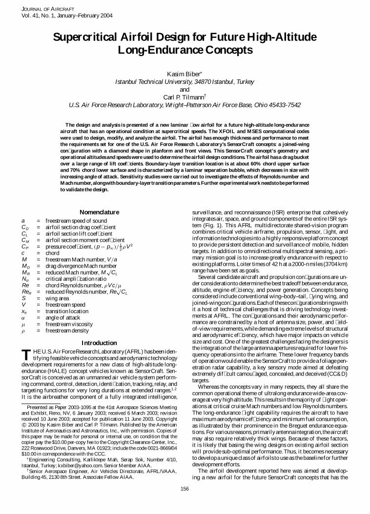
Fig. 9 Computed (MSES) airfoil performance showing the effects ofReynolds number on lift, drag, and pitching moment characteristics atRe = 1 and 3 ££ 106, Mach numbers of 0.55 and 0.60, and Ncr = 9.
Fig. 10 Computed (MSES) total drag and wave drag variation (anddivergence) Re = 3 ££ 106 and Ncr = 9, with Mach number: ——, � xed® = 2 deg and - - - -, CL = 1.
to the increased compressibility effects. The drag increase is morepronounced for the � xed CL case than that for the � xed angle-of-attack case at the transonic regime because the code maintains therequested CL by further increasing ®, leading to yet more severeshock-induced boundary-layer separation and corresponding lossof lift. It is, however, desirable to have the smallest possible initialrate of drag increase beyond MD because the best cruise perfor-mance is obtained at a Mach number possibly 0.02–0.03 excess ofMD (Ref. 12).
Figure 11 shows the variationofCL with Mach number for a � xed® D 2 deg, as well as the variation in ® with Mach number requiredto maintain a � xed CL D 1. The � xed-® lift coef� cient continues toincrease with Mach number to its maximum value of 1.05 at Machnumber of 0.57. Beyond this maximum, lift coef� cient decreasesrapidly due to the shock formation and related � ow separation fromthe airfoil upper surface. The ® required to maintain a � xed CL of1.0 decreases with increasingMach number to a minimum value of1.68, and then it shows a dramatic increasebeyond the lift-divergentMach number of 0.57.
Fig. 11 Computed (MSES) lift coef� cient and AOA variation withMach number at Re = 3 ££ 106 and Ncr = 9: ——, � xed ® = 2 deg and– – –, � xed CL = 1.
Fig. 12 Computed (MSES) surface pressure distribution for theSCR20-A airfoil exhibiting a critical Mach number of 0.54 and a criticalpressure coef� cient of ¡¡1.75, at ® = 2 deg, Re = 3 ££ 106 , and Ncr = 9.
The criticalMach number is of importance to determine the onsetof shock formation for given angle-of-attack and � ow conditions.Surface pressure data were obtained for various Mach numbers be-low MD . As shown in Fig. 12, the critical pressure coef� cient of¡1.75 was predicted to be achieved at a critical Mach number of0.54 for Re D 3 £ 106 and ® D 2 deg. As expected, this is slightlylower than the drag divergence Mach number of 0.58. When thewing sweep angle of 35 deg is considered, the SensorCraft wing,in fact, has a critical Mach number of 0.66 and a drag divergenceMach number of 0.70 (as opposed to the critical and divergenceMach numbers normal to the leading edge of 0.54 and 0.58 indi-cated, respectively,in this two-dimensionalairfoil analysis). Noticealso the very high value of lift-to-drag ratio of 145 for the airfoilshown in Fig. 12. In fact, the critical speeds set by the surface pres-sure distribution are not directly related to the drag or lift criticalspeeds.19 This is mainly because the drag begins to increase any-time there is either supersonic � ow or � ow separation on any partof wing. If the � ow separation does not occur at subcritical speeds,then there is no drag increase until reaching the critical Mach.
Figure 13 shows surface pressure distributions for Mach num-bers ranging from 0.50 to 0.70 in increments of 0.04, including thedata already presented in Fig. 12. At subcriticalMach numbers, theupper surface pressure has a gradual increase of negative pressuresover the forward part probably until a point where the laminar sep-aration bubble has its maximum thickness, followed by a pressurerise to the trailing edge. This is similar to the shape of roof-typepressuredistributions,which delays critical Mach number by virtue

BIBER AND TILMANN 161
Fig. 13 Computed (MSES) surface pressure distributions for theSCR20-A airfoil at Mach numbers of 0.50,0.54,0.58,0.62,0.66 and 0.70,showing the effects of supercritical speeds at ® = 2 deg,Re = 3 ££ 106, andNcr = 9.
of a uniform velocity at the design condition (also Fig 6). As theMach number increases beyond its critical value of 0.54, there is adramatic change of surface pressures in the separation bubble re-gion. The suction level basically moves to its maximum value atthe supercriticalMach number of 0.58. This is probably due to thethickening of the boundary layer by the presence of locally super-sonic � ow embedded in the subsonic outer � ow. The supersonic� ow extendsover a region in which there is near isentropic � ow andshock-free compression waves. However, at Mach numbers above0.58, the supersonic region is terminated by a normal shock andassociated � ow separation,which causes a decrease of not only themaximum suction pressure, but also a sharp decrease in lift andincrease in drag coef� cient, as shown in data tabulation of Fig. 13and as was plotted in Figs. 10 and 11. Notice also the decrease inmagnitude of pitching moment coef� cient as the Mach number israised above the drag divergence Mach.
Figure 14 shows the pressure contour to better illustrate shockformation and associated � ow events at the same Mach number and� ow conditions as the surface pressure distributions presented inFig. 13. The shock formation is clearly visible in the dense regionof pressure contours at the location of the separation bubble. Pre-compression waves are initially weak at Mach 0.54, but they getstronger with increase of Mach number and are terminated with anormal shock wave. They separate the laminar boundary layer wellaheadof the � rst shockwave,which impingeson the free-shearlayerand re� ects as an expansionwave.The so-calledshock-induced� owseparation, clearly exhibited at Mach 0.62 and 0.66, limits the op-erational range of airfoils designed for HALE applications.
Airfoil Polars for SensorCraftThe SCR20-A airfoil performancewas analyzed by using MSES
for both design and the SensorCraft � ow conditions presented inTable 1. This investigation included studies of polar performanceand its sensitivityto variousparameters includingReynoldsnumber,Mach number, critical ampli� cation factor, and wing loading.
The airfoil can operate at a cruise speed slightly above the criticalMach number. At this Mach number, there is a progress of shock-induced � ow separation on the airfoil upper surface, as shown inpressure contour plots of Fig. 14. As Mach number is further in-creased, massive separation ensues. This shock induced separationis typically very unsteady,creating large � uctuationsand excitationof the wing structure. This phenomenon is known as Mach buffet,and it imposes limitations on the operational � ight regime. The air-foil should be brought to a lower altitude, where it would requirea lower lift coef� cient to maintain the same lift at a given Machnumber. This would create a weaker shock and help avoid the Machbuffet. This type of de� ciency in airfoil behavior is an off-designcondition and clearly not acceptable. For a constant lift condition,the off-design may also be encountered with increasingaltitudes asthe aircraftweight decreaseswhile consumingfuel in cruising� ight.
Fig. 14 Effects of the shock wave and its induced separation in pres-sure contours as the � ow passes the critical � ow condition; MSES pre-dictions at M = 0.54, 0.58, 0.62, and 0.66, at ® = 2 deg, Re = 3 ££ 106 , andNcr = 9.
162 BIBER AND TILMANN
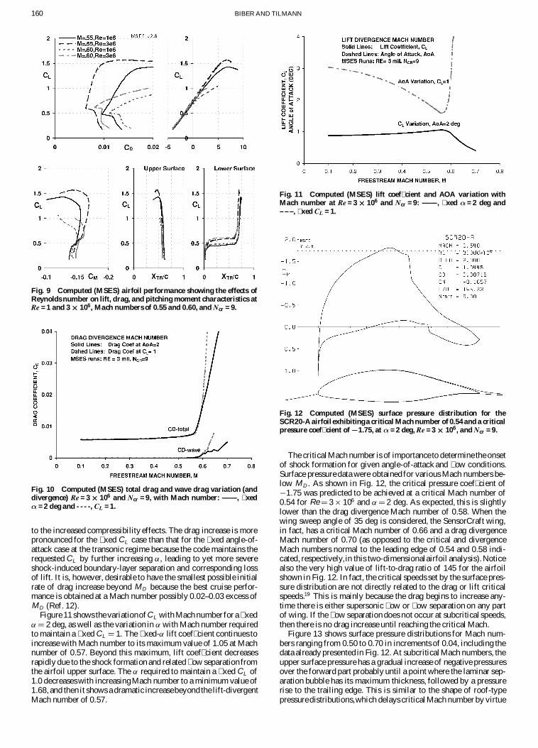
Fig. 15 Calculated (MSES) airfoil performance with constant lift MRand ReR parameters at 10,000-, 55,000-, 60,000-, 65,000-, and 70,000-ftaltitude (MR and ReR parameter values as given in Table 1), Ncr = 9.
Fig. 16 MSES prediction of polars at 10,000-, 55,000-, 60,000-, and65,000-ft altitudes, Ncr = 9, obtained by ——, constant lift MR and ReRparameters - - - -, holding standard Re and M constant.
To study the difference between the normal design and off-thedesign condition better, in Ref. 11 it is suggested to use of theconstant-lift polar in which the reduced Mach number and reducedReynolds number are held � xed, instead of the traditional Machnumber and Reynolds number. Figure 15 shows the lift, drag, andpitching moment characteristics of the airfoil for SensorCraft al-titudes of 10,000, 55,000, 60,000, 65,000, and 70,000 ft (at thecorresponding reduced Reynolds and Mach numbers from Table 1at takeoff maximum weight). The performancetrends are similar tothose presented earlier. The drag bucket clearly shifts upward withincreasing altitude, and its operational (usable CL ) range becomesvery narrow at 70,000 ft.
Figure 16 shows a comparison of these constant-lift drag polarsat 10,000-, 55,000-, 60,000-, and 65,000-ft altitudes,with those ob-tained by holding standard Reynolds and Mach numbers constant.With increasingaltitude, the constant-liftpolars shift upward whilethe drag bucket of conventional polars expands over a larger rangeof lift coef� cient with a decreasing slope (@CL =@CD). Each corre-sponding pair of polars for 10,000-, 55,000-, and 60,000-ft cases
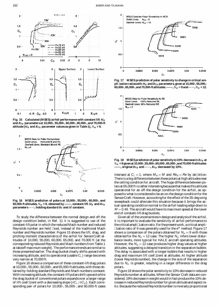
Fig. 17 MSES prediction of polar sensitivity to change in critical am-pli� cation ratios with MR and ReR parameters, given at 10,000-,55,000,-60,000-,65,000-,and 70,000-ftaltitudes: ——, Ncr = 9 and - - - -, Ncr = 12.
Fig. 18 MSES prediction of polarsensitivity to 10% decrease in ReR atNcr = 9 given at 10,000-,55,000-,60,000-,65,000-,and 70,000-ftaltitudes:——, original ReR and - - - -, ReR decreased by 10%.
intersect at CL D 1, where MR D M and ReR D Re by de� nition.There is a big differencebetween these polars at high altitudes nearthe ceiling condition for aircraft. The huge difference between po-lars at 65,000 ft is rather interestingbecause that makes this altitudeoperational for an off-the design condition for the airfoil, as op-posed to what is consideredto be an on-the design condition for theSensorCraft.However, accounting for the effect of the 35-deg wingsweepback could alleviate this situation because it brings the ac-tual operating condition normal to the airfoil leading edge down toM D 0:49. The aircraft would have its maximum speed at the lowerend of constant-lift drag buckets.
Given all of the uncertaintiesin design and analysisof the airfoil,it is important to evaluate the sensitivity of airfoil performance tothe criticalampli� cation ratio. For thepresentwork, a criticalampli-� cation ratio of 9 was generally used for the eN method. Figure 17shows a comparison of the polars obtained for Ncr D 9 with thoseobtained for the Ncr D 12 case. The higher Ncr infers lower distur-bance levels, more typical for HALE aircraft operating altitudes.However, the Ncr D 12 case produces higher drag values at higheraltitudes, suggesting a delayed transition in the separation bubble.The delay is associated with a longer bubble that results in higherdrag and maximum lift coef� cient at altitudes. At higher altitude(lower Reynolds number), the change in the size of the separationdue to Ncr is greater, resulting in a larger difference in the dragpolars.
Figure 18 shows the polar sensitivity to 10% decrease in reducedReynolds number at altitudes. When the Sensor Craft data are con-sidered, 19% decrease in weight would in fact produce the 10% de-crease in reducedReynolds number for given altitude and aspect ra-tio. Because the reducedReynolds number is inversely proportional
BIBER AND TILMANN 163
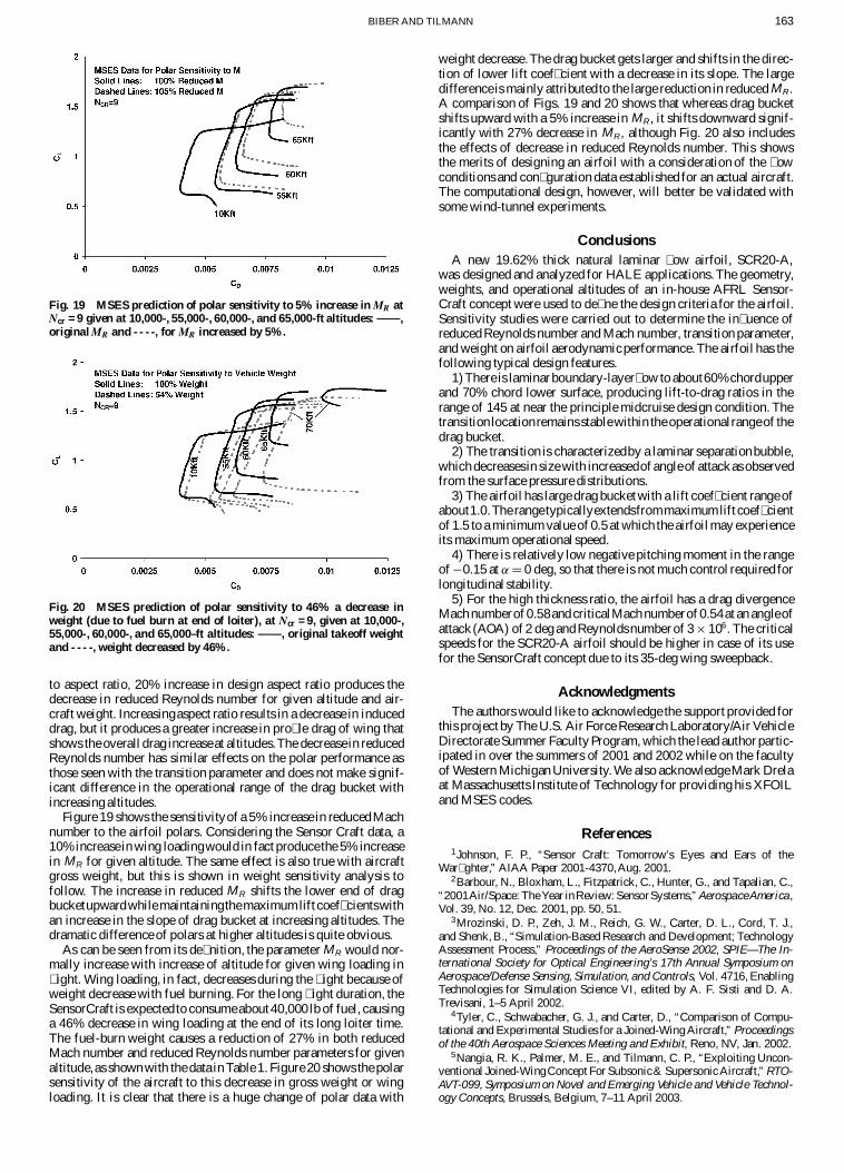
Fig. 19 MSES prediction of polar sensitivity to 5% increase in MR atNcr = 9 given at 10,000-, 55,000-, 60,000-, and 65,000-ft altitudes: ——,original MR and - - - -, for MR increased by 5%.
Fig. 20 MSES prediction of polar sensitivity to 46% a decrease inweight (due to fuel burn at end of loiter), at Ncr = 9, given at 10,000-,55,000-, 60,000-, and 65,000–ft altitudes: ——, original takeoff weightand - - - -, weight decreased by 46%.
to aspect ratio, 20% increase in design aspect ratio produces thedecrease in reduced Reynolds number for given altitude and air-craft weight. Increasingaspect ratio results in a decrease in induceddrag, but it produces a greater increase in pro� le drag of wing thatshows the overall drag increaseat altitudes.The decreasein reducedReynolds number has similar effects on the polar performance asthose seen with the transition parameter and does not make signif-icant difference in the operational range of the drag bucket withincreasing altitudes.
Figure 19 shows the sensitivityof a 5% increase in reducedMachnumber to the airfoil polars. Considering the Sensor Craft data, a10% increasein wing loadingwould in fact producethe 5% increasein MR for given altitude. The same effect is also true with aircraftgross weight, but this is shown in weight sensitivity analysis tofollow. The increase in reduced MR shifts the lower end of dragbucketupwardwhile maintainingthemaximumlift coef� cientswithan increase in the slope of drag bucket at increasing altitudes. Thedramatic difference of polars at higher altitudes is quite obvious.
As can be seen from its de� nition, the parameter MR would nor-mally increase with increase of altitude for given wing loading in� ight. Wing loading, in fact, decreases during the � ight because ofweight decrease with fuel burning. For the long � ight duration, theSensorCraft is expected to consumeabout40,000 lb of fuel, causinga 46% decrease in wing loading at the end of its long loiter time.The fuel-burn weight causes a reduction of 27% in both reducedMach number and reduced Reynolds number parameters for givenaltitude,as shown with the data in Table 1. Figure 20 shows the polarsensitivity of the aircraft to this decrease in gross weight or wingloading. It is clear that there is a huge change of polar data with
weight decrease.The drag bucket gets larger and shifts in the direc-tion of lower lift coef� cient with a decrease in its slope. The largedifference is mainly attributed to the large reduction in reduced MR .A comparison of Figs. 19 and 20 shows that whereas drag bucketshifts upward with a 5% increase in MR , it shifts downward signif-icantly with 27% decrease in MR , although Fig. 20 also includesthe effects of decrease in reduced Reynolds number. This showsthe merits of designing an airfoil with a consideration of the � owconditions and con� guration data established for an actual aircraft.The computational design, however, will better be validated withsome wind-tunnel experiments.
ConclusionsA new 19.62% thick natural laminar � ow airfoil, SCR20-A,
was designed and analyzed for HALE applications.The geometry,weights, and operational altitudes of an in-house AFRL Sensor-Craft concept were used to de� ne the design criteria for the airfoil.Sensitivity studies were carried out to determine the in� uence ofreduced Reynolds number and Mach number, transition parameter,and weight on airfoil aerodynamicperformance.The airfoil has thefollowing typical design features.
1)There is laminar boundary-layer� ow to about60%chordupperand 70% chord lower surface, producing lift-to-drag ratios in therange of 145 at near the principle midcruise design condition. Thetransition locationremains stablewithin the operationalrangeof thedrag bucket.
2) The transition is characterizedby a laminar separationbubble,which decreasesin size with increasedof angleof attackas observedfrom the surface pressure distributions.
3) The airfoil has large drag bucket with a lift coef� cient range ofabout1.0.The rangetypicallyextendsfrommaximumlift coef� cientof 1.5 to a minimum value of 0.5 at which the airfoilmay experienceits maximum operational speed.
4) There is relatively low negative pitching moment in the rangeof ¡0.15 at ® D 0 deg, so that there is not much control required forlongitudinal stability.
5) For the high thickness ratio, the airfoil has a drag divergenceMach numberof 0.58and criticalMach numberof 0.54at an angleofattack (AOA) of 2 deg and Reynolds numberof 3 £ 106 . The criticalspeeds for the SCR20-A airfoil should be higher in case of its usefor the SensorCraft concept due to its 35-deg wing sweepback.
AcknowledgmentsThe authors would like to acknowledge the support provided for
this project by The U.S. Air Force Research Laboratory/Air VehicleDirectorate Summer Faculty Program, which the lead author partic-ipated in over the summers of 2001 and 2002 while on the facultyof Western Michigan University. We also acknowledgeMark Drelaat Massachusetts Institute of Technology for providing his XFOILand MSES codes.
References1Johnson, F. P., “Sensor Craft: Tomorrow’s Eyes and Ears of the
War� ghter,” AIAA Paper 2001-4370,Aug. 2001.2Barbour, N., Bloxham, L., Fitzpatrick, C., Hunter, G., and Tapalian, C.,
“2001Air/Space: The Year inReview: SensorSystems,” AerospaceAmerica,Vol. 39, No. 12, Dec. 2001, pp. 50, 51.
3Mrozinski, D. P., Zeh, J. M., Reich, G. W., Carter, D. L., Cord, T. J.,and Shenk, B., “Simulation-Based Research and Development; TechnologyAssessment Process,” Proceedings of the AeroSense 2002, SPIE—The In-ternational Society for Optical Engineering’s 17th Annual Symposium onAerospace/Defense Sensing, Simulation, and Controls, Vol. 4716, EnablingTechnologies for Simulation Science VI, edited by A. F. Sisti and D. A.Trevisani, 1–5 April 2002.
4Tyler, C., Schwabacher, G. J., and Carter, D., “Comparison of Compu-tational and Experimental Studies for a Joined-Wing Aircraft,” Proceedingsof the 40th Aerospace Sciences Meeting and Exhibit, Reno, NV, Jan. 2002.
5Nangia, R. K., Palmer, M. E., and Tilmann, C. P., “Exploiting Uncon-ventional Joined-WingConcept For Subsonic& Supersonic Aircraft,” RTO-AVT-099, Symposium on Novel and Emerging Vehicle and Vehicle Technol-ogy Concepts, Brussels, Belgium, 7–11 April 2003.

164 BIBER AND TILMANN
6Blair, M., and Can� eld, R. A., “A Joined-Wing Structural Weight Mod-eling Study,” Proceedings of the 43rd AIAA/ASME/ASCE/AHS/ASC Struc-tures, Structural Dynamics, and Materials Conference, Denver, CO, April2002.
7Reich, G., Raveh, D., and Zink, P., “Application of Active AeroelasticWing Technology to a Joined-Wing SensorCraft,” Proceedings of the 43rdAIAA/ASME/ASCE/AHS/ASC Structures, Structural Dynamics, and Materi-als Conference, Denver, CO, April 2002.
8Nangia, R. K., Palmer, M. E., and Tilmann, C. P., “On Design of Uncon-ventional High Aspect Ratio Joined-Wing Type Aircraft Con� gurations,”International Council of the Aeronautical Sciences, Toronto, Canada, Sept.2002.
9Nangia, R. K., Palmer, M. E., and Tilmann, C. P., “UnconventionalHighAspect Ratio Joined-Wing Aircraft Incorporating Laminar Flow,” AIAAPaper 2003-3927, June 2003.
10Nangia, R. K., Palmer, M. E., and Tilmann, C. P., “UnconventionalHighAspect Ratio Joined-Wing Aircraft with Aft- and Forward-Swept Wing-Tips,” AIAA Paper 2003-0605, Jan. 2003.
11Drela, M., “TransonicLow-ReynoldsNumber Airfoils,” Journal of Air-craft, Vol. 29, No. 6, 1992, pp. 1106–1113.
12Torenbeek,E., Synthesisof SubsonicAirplaneDesign, Delft Univ.Press,Kluwer Academic, Delft, The Netherlands, 1982, pp. 241–252.
13Greer, D., Hamory, P., Krake, K., and Drela, M., “Design and Pre-dictions for a High-Altitude (Low Reynolds Number) Aerodynamic FlightExperiment,” AIAA Paper 99-3183, June 1999.
14Drela, M., “A User’s Guide to MSES 2.8,” Computational AerospaceSciences Lab., Massachusetts Inst. of Technology, Cambridge, MA, May1995.
15Tilmann,C. P.,Brandt,L.B.,Russell,W. J., Ramsay, R. R., andHohn,T.,“Development and Validation of Airfoils for Global Range Transports,” Pro-ceedings of the 18th AIAA Applied Aerodynamics Conference, Denver, CO,Aug. 2000.
16Tilmann, C. P., “Enhancement of Transonic Airfoil Perfor-mance Using Pulsed Jets for Separation Control,” Proceedings ofthe 39th AIAA Aerospace Sciences Meeting and Exhibit, Reno, NV,Jan. 2001.
17Selig, M. S., Maughmer, M. D., and Somers, D. M., “Natural LaminarFlowAirfoil forGeneral AviationApplications,”Journalof Aircraft, Vol. 32,No. 4, 1995, pp. 710–715.
18Maughmer, M. D., and Somers, D., “Design and Experimental Resultsfor a High-Altitude, Long-Endurance Airfoil,” Journal of Aircraft, Vol. 26,No. 2, 1989, pp. 148–153.
19Perkins, C. D., and Hage, R. E., Airplane Performance Stability andControl, Wiley, New York, 1949, pp. 44–49.