beyond object-oriented technology: where current...
TRANSCRIPT

HUMAN-COMPUTER INTERACTION, 1995, Volume 10, pp. 79-119 Copyright © 1995, Lawrence Erlbaum Associates, Inc.
Beyond Object-Oriented Technology: Where Current
Approaches Fall Short
Gerhard Fischer University of Colorado, Boulder
David Redmiles University of California, Irvine
Lloyd Williams Software Engineering Research
Gretchen I. Puhr University of Colorado, Boulder
Atsushi Aoki and Kumiyo Nakakoji Software Research Associates, Inc.
Gerhard Fischer, a Professor of Computer Science and Member of the Institute of Cognitive Science at the University of Colorado, has been involved with object-oriented (00) design approaches for the last 15 years and is concentrating on the creation and evaluation of domain-oriented design environments based on an 00 layered architecture. David Redmiles, an Assistant Professor of Computer Science, focuses his research on improving the software development process through cognitive studies and innovative technologies. As President of Software Engineering Research, Lloyd Williams does work that emphasizes methods, tools, and support environments for the description and analysis of software designs. Gretchen I. Puhr, a PhD candidate in Information Systems, has been involved with teaching 00 systems development for 5 years and is interested in the cognitive aspects of software reuse. Atsushi Aoki, a Software Engineering Researcher at the Software Engineering Laboratory, Software Research Associates, has been working in the Smalltalk environment since 1984. Kumiyo Nakakoji works for Software Research Associates and is interested in cross-cultural considerations in design and systems.

80 FISCHER ET AL.
CONTENTS
1. INTRODUCTION 2. A COGNITIVE MODEL OF OBJECT-ORIENTED DEVELOPMENT 3. EVOLUTION IN 00 SOFrWARE DEVELOPMENT
3.1. Where Current 00 Technology Falls Short 3.2. Beyond Object Orientation 3.3. Reference and Hierarchy Factors: Metrics to Support Evolution
4. REUSE AND REDESIGN 4.1. Where Current 00 Technology Falls Short 4.2. Beyond Object Orientation 4.3. Explainer: A Tool to Support Reuse and Redesign
5. DOMAIN ORIENTATION 5.1. Where Current 00 Technology Falls Short 5.2. Beyond Object Orientation 5.3. Knowing-In-Design: A Tool to Support Domain Orientation
6. CONCLUSIONS
ABSTRACT
Object-oriented (00) technology has been heralded as a solution to the problems of software engineering. The claims are that 00 technology promotes understandability, extensibility, evolvability, reusability, and maintainability of systems and that 00 systems are easy to understand and use. However, this technology has not been as successful as expected. An analysis of experiences and empirical studies reveals that the problem is not the technology per se but that the technology provides no support to software developers in performing the processes the technology requires. We present a cognitive model of software development that details the challenges software developers face in using 00 technology. The model focuses on three aspects of software development-evolution, reuse and redesign, and domain orientation. We motivate this model with a variety of firsthand experiences and use it to assess current 00 technology. Further, we present tools and evaluations that substantiate parts of this model. The model and tools indicate directions for future software development environments, looking beyond the technological possibilities of 00 languages and beyond the context of individual developers and projects.
1. INTRODUCTION
Object-oriented (00) technology has been heralded as a way to make software development easier, faster, and more reliable (ACM, 1990, 1992). Among the claimed software benefits of 00 technology are understandability, extensibility, evolvability, reusability, and maintainability, all of

OBJECT-ORIENTED TECHNOLOGY 81
which are technically well motivated. The basic 00 principle of encapsulating data and procedures into a single unit, the "object," with a well-defined interface facilitates many of these objectives (Meyer, 1987). Object libraries can evolve and be made available to designers, allowing designers to build new applications from proven constructs in the library. Languages such as C++, Smalltalk, and Common Lisp Object System (CLOS) are at the forefront of such work today. Furthermore, object libraries can build upon one another to support a layered architecture and thus reduce the conceptual distance between a problem and its solution (Fischer & Lemke, 1988). 00 technology allows software developers to choose objects that directly model problem domain concepts, resulting in systems the structures of which more nearly correspond to those of problem domains (Rosson & Alpert, 1990). This has led to what is termed a "seamless" approach to 00 development: The structures that are identified during analysis are often carried through into design and implementation (Henderson-Sellers, 1992).
Despite these claims, our collective experience (as well as that of others) has revealed that current 00 technology fails in practice to achieve all its claimed benefits. Central to understanding this shortfall is Brooks's (1987) well-stated observation that software technologies have focused too much on the "accidents" (or software artifacts) and not enough on the "essence" (or human creative resource) of software engineering. Software technologies support the downstream activities (e.g., translation of specification and programming languages) but not the upstream activities (e.g., problem analysis and selection of abstractions) (Swartout & Balzer, 1982). These introductory observations indicate the need for an analysis of 00 technology that focuses on the needs of the human software developers (Fischer 1987) more than on the formal properties of classes, instances, and inheritance (Stefik & Bobrow 1986). We present such an analysis based on a human-centered model of software development that has grown out of our diverse academic and industrial experiences. The specific model we describe incorporates elements of evolutionary design, reuse and redesign, and domain orientation. The model is a cognitive theory of software development in the sense that it focuses not on the technical accommodation of software objects but on the accommodation of the human developers in their interaction with the software objects. This point of view leads us to address questions such as:
1. What processes of software development are difficult for people? 2. Which processes can be supported by tools-and how? 3. What evidence supports this particular model? 4. How do existing 00 technologies compare? 5. How do prototype tools we have developed perform?

82 FISCHER ET AL.
In developing our model, we relied in part on our varied academic and industrial experience and case studies that span many years, projects, and settings. Although such evidence lacks the rigor of highly structured experiments, it also lacks the artificiality of experiments. The use of anecdotal evidence, although uncommon in cognitive psychology, is common in engineering disciplines. An example is the use of critical incidents for product safety and the use of design failures in civil engineering (Petroski, 1985). The reader should also bear in mind that some of the analysis is from areas outside software development, and the model is more one of general design than one of 00 programming. 00 technology presents not simply a new way to program but a new way for people to think about problem domains. The gravest cognitive challenges are not in the downstream activities of programming but in the upstream activities of analysis and abstraction, as already noted. Analogies to other areas in which objects have long been a medium of problem solving should not be overlooked (Simon, 1981, pp. 200-203).
The experiential evidence is used to motivate our model. Together with the model, it provides a framework for assessing the areas in which current 00 technology falls short of its promise. Our assessment of 00 technology may seem negative at times, especially considering the subtitle of this article. This emphasizes our belief that much can be learned by analyzing failures. We believe that 00 technology is an enabling technology and have argued so in the past (Aoki, 1993; Fischer, Lemke, & Rathke, 1987; Ward & Williams, 1990b). Addressing its shortcomings widens the scope of problem situations in which the technology may be applied.
The remainder of the article is organized as follows. Section 2 presents a model of 00 development that emphasizes evolution, reuse and redesign, and domain orientation. Sections 3, 4, and 5 explore in detail how 00 technology addresses each of these concepts, respectively. Each section presents the rationale behind the claim, summarizes empirical and experiential evidence bearing on it, and assesses where current 00 technology is with respect to meeting its promise. Each section concludes with a description of our approach and a prototype method or tool that moves us beyond the current technology. Section 6 presents a summary and draws some general conclusions.
2. A COGNITIVE MODEL OF OBJECT-ORIENTED DEVELOPMENT
Software development requires a developer to transform a general, informal understanding of a goal into a formal model using operators and components interpretable by the computer. fv1any cognitive models focus on this process from the perspective of the cognitive processes internal to a developer. For example, they focus on models of how software developers might retrieve and apply plans and schemas (Adelson & Soloway,

OBJECT-ORIENTED TECHNOLOGY 83
1985; Rist, 1989) or bring to bear other knowledge for software comprehension (Pennington, 1987). Although these models make an important contribution to our understanding of individuals, the process of software development is a cooperative process among many individuals and different kinds of artifacts. With respect to reuse, we have recognized that this cooperation can span long time intervals as well, raising many issues related to the evolution of software objects (Fischer, McCall, Ostwald, Reeves, & Shipman, 1993). This point of view gives rise to a cognitive model that emphasizes a longer period of time and focuses on the interaction of the human players with the artifacts involved (Hutchins 1993; Norman 1993).
Design methodologists (Rittel, 1984; Schoen, 1983) have emphasized the need for integrating problem framing and problem solving. They have argued convincingly that one cannot gather information meaningfully unless one has understood a problem, but one cannot understand a problem without information about it. For instance, Curtis, Krasner, and Iscoe (1988) observed that the predominant activity in designing complex systems is the participants' teaching and instructing one another-that understanding the problem is the problem. Because complex problems require more knowledge than anyone person possesses, communication and collaboration among all the involved stakeholders are necessary (Ehn, 1988; Greenbaum & Kyng, 1991). Professional practice has at least as much to do with defining a problem as with solving a problem. New requirements emerge during development because they cannot be identified until portions of the system have been designed or implemented (Fischer & Reeves, 1992). The conceptual structures underlying complex software systems are too complicated to be specified accurately in advance and too complex to be built faultlessly (Brooks, 1987). Specification and implementation have to coevolve (Swartout & Balzer, 1982), requiring a tighter integration of the frequently separated stages of software development-analysis, design, speCification, and implementation. Thus, evolution occurs as feedback from partial solutions improves the developers' understanding of the problem.
These considerations on cognitive processes and design theories have led us to develop a cognitive model of 00 development. The model focuses on three aspects of 00 development-evolution, reuse and redesign, and domain orientation. Figure 1 is used as a basis to explain this focus. The diagram includes three types of 00 software components-specific projects composed of instances of objects; libraries of object classes from which instances are made; and frameworks that define recurring patterns of interaction between classes of objects, potentially classes from different libraries (for descriptions of these terms, see Deutsch, 1989; Johnson & Foote, 1988).
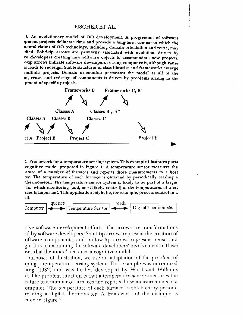
Figure 1 illustrates that, in our model, evolution is driven by software developers reusing and redesigning software components in the context of
FISCHER ET AL.
1. An evolutionary model of 00 development. A progression of software Ipment projects delineate time and provide a long-term context in which the nental claims of 00 technology, including domain orientation and reuse, may died. Solid-tip arrows are primarily associated with evolution, driven by re developers creating new software objects to accommodate new projects. V'-tip arrows indicate software developers reusing components, although reuse ~s leads to redeSign. Stable structures of class libraries and frameworks emerge nultiple projects. Domain orientation permeates the model as all of the In, reuse, and redesign of components is driven by problems arising in the pment of specific projects.
Frameworks B Frameworks C, B'
Classes A'
Classes A Classes B
I Classes B I, A"
Classes C
ct A Project B Project C Project Y
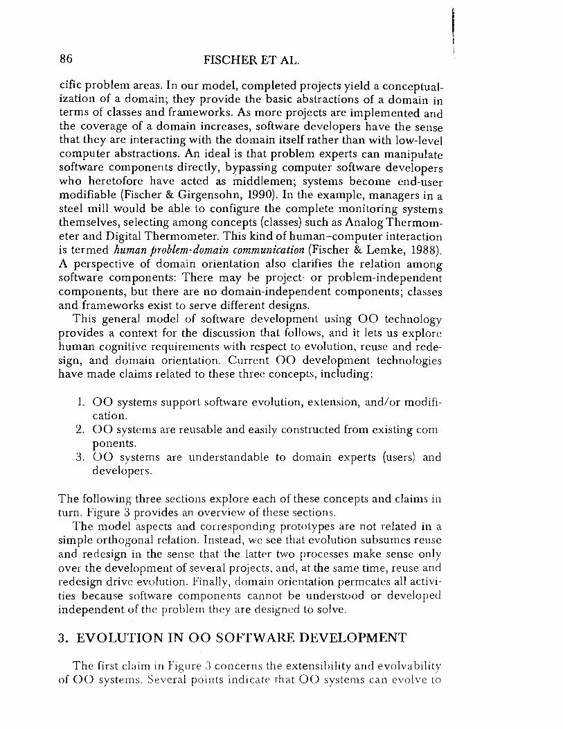
!. Framework for a temperature sensing system. This example illustrates parts cognitive model proposed in Figure 1. A temperature sensor measures the 'ature of a number of furnaces and reports those measurements to a host ter. The temperature of each furnace is obtained by periodically reading a thermometer. The temperature sensor system is likely to be part of a larger for which monitoring (and, most likely, control) of the temperatures of a set
.lces is important This application might be, for example, process control in a ill.
queries reads I I :omputer I ~ .. Temperature Sensor ~ • Digital Thermometer
sive software development efforts. The arrows are transformations ~d by software developers. Solid-tip arrows represent the creation of oftware components, and hollow-tip arrows represent reuse and gu. It is in examining the software developers' involvement in these ;ses that the model becomes a cognitive model. purposes of illustration, we use an adaptation of the problem of
>ping a temperature sensing system. This example was introduced lUng (1982) and was further developed by Ward and Williams l). The problem situation is that a temperature sensor measures the rature of a number of furnaces and reports those measurements to a omputer. The temperature of each furnace is obtained by periodireading a digital thermometer. A framework of the example is med in Figure 2.
I

OBJECT-ORIENTED TECHNOLOGY 85
In our model, illustrated in Figure 1, evolution implies that software components are expected to change over time; that is, class definitions may be refined with respect to the.ir attributes and methods, and libraries may be repartitioned to contain different classes. Our model stresses that these changes are driven by successive software development projects; the evolutionary scale in Figure 1 is measured by a progression of projects (see also Berard, 1993). A successive project could be a revision of an earlier one or a new development in the same domain. For instance, in Figure 1, Project A might be the development of a system for the temperature sensor problem illustrated in Figure 2. The Digital Thermometer and Temperature Sensor classes would be developed; Digital Thermometer would have instance methods for reporting temperature, and Temperature Sensor would have instance methods for requesting and interpreting temperature readings from thermometers. With this one project, all the classes might be placed in a single class library, such as Classes A in Figure 1. A new project might be to adapt the sensing system to work with analog thermometers. (Strictly speaking, the digital thermometer device would also have an analog component. However, we use the digital-analog distinction for simplicity in denoting two thermometer device types requiring different software interfaces.) The software developers might choose to generalize the framework to have a Thermometer class with Digital Thermometer and Analog Thermometer subclasses; the two thermometers might have, for instance, different communications requirements and hence need different attributes for buffers and methods for reading. Although a single project is not always sufficient for generalizing patterns of class interaction, together Projects A and B yield a common framework illustrated in Figure 2 and corresponding to Framework B in Figure 1.
Reuse means that existing software components can be incorporated into the solutions of new problems, and redesign means that some existing components might be adapted to fit new problems (Fischer et al., 1987). In Figure 1, the arrow pointing downward to Project B is used to illustrate that some classes from the previous project may be reused. In our example, the Temperature Sensor class was reused and did not change. The arrow leading upward from Project B is used to illustrate a synthesis of new classes such as Analog Thermometer and Thermometer and the redesign of the former class, Digital Thermometer, to be a subclass of the new class, Thermometer. A further redesign might be that all the Thermometer classes are partitioned into their own class library, Classes B, leaving the modified class library, Classes A'. Reuse and redesign go hand in hand with evolution: Components evolve so that they may be reused in other contexts, and the reuse and redesign of those components lead to further evolutionary changes, which in turn support continued reuse.
Finally, domain orientation means that all the software componentsframeworks, classes, and instances in projects-are grounded in spe-
86 FISCHER ET AL.
cific problem areas. In our model, completed projects yield a conceptualization of a domain; they provide the basic abstractions of a domain in terms of classes and frameworks. As more projects are implemented and the coverage of a domain increases, software developers have the sense that they are interacting with the domain itself rather than with low-level computer abstractions. An ideal is that problem experts can manipulate software components directly, brpassing computer software developers who heretofore have acted as middlemen; systems become end-user modifiable (Fischer & Girgensohn, 1990). In the example, managers in a steel mill would be able to configure the complete monitoring systems themselves, selecting among concepts (classes) such as Analog Thermometer and Digital Thermometer. This kind of human-computer interaction is termed human problem-domain communication (Fischer & Lemke, 1988). A perspective of domain orientation also clarifies the relation among software components: There may be project- or problem-independent components, but there are no domain-independent components; classes and frameworks exist to serve different designs.
This general model of software development using 00 technology provides a context for the discussion that follows, and it lets us explore human cognitive requirements with respect to evolution, reuse and redesign, and domain orientation. Current 00 development technologies have made claims related to these three concepts, including:
1. 00 systems support software evolution, extension, and/or modification.
2. 00 systems are reusable and easily constructed from existing components.
3. 00 systems are understandable to domain experts (users) and developers.
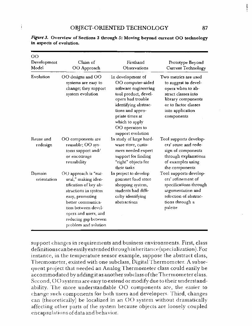
The following three sections explore each of these concepts and claims in turn. Figure 3 provides an overview of these sections.
The model aspects and corresponding prototypes are not related in a simple orthogonal relation. Instead, we see that evolution subsumes reuse and redesign in the sense that the latter two processes make sense only over the development of several projects, and, at the same time, reuse and redesign drive evolution. Finally, domain orientation permeates all activities because software components cannot be understood or developed independent of the problem they are designed to solve.
3. EVOLUTION IN 00 SOFTWARE DEVELOPMENT
The first claim in Fi·gure 3 concerns the extensibility and evolvability of 00 systems. Several points indicate that 00 systems can evolve to
1 ,
OBJECT-ORIENTED TECHNOLOGY 87
Figure 3. Overview of Sections 3 through 5: Moving beyond current 00 technology in aspects of evolution.
00 Development Claim of Firsthand Prototype Beyond Model 00 Approach Observations Current Technology
Evolution 00 designs and 00 In development of Two metrics are used systems are easy to 00 computer-aided to suggest to devel-change; they support software engineering opers when to ab-system evolution tool product, devel- stract classes into
opers had trouble library components identifying abstrac- or to factor classes tions and appro- into application priate times at components which to apply 00 operators to support evolution
Reuse and 00 components are In study of large hard- Tool supports develop-redesign reusable; 00 sys- ware store, custo- ers' reuse and rede-
terns support and/ mers needed expert sign of components or encourage support for finding through explanations reusability "right" objects for of examples using
their tasks the components Domain 00 approach is "nat- In project to develop Tool supports develop-
orientation ural," making iden- gourmet food store ers' refinement of tification of key ab- shopping system, specifications through stractions in system students had diffi- argumentation and
easy, promoting culty identifying selection of abstrac-better communica- abstractions tions through a tion between devel- palette opers and users, and reducing gap between problem and solution
support changes in requirements and business environments. First, class definitions can be easilyextendedthroughinheritance (specialization).For instance, in the temperature sensor example, suppose the abstract class, Thermometer, existed with one subclass, Digital Thermometer. A subsequent project that needed an Analog Thermometer class could easily be accommodated by adding it as another subclass of the Thermometer class. Second, 00 systems are easy to extend or modify due to their understandability. The more understandable 00 components are, the easier to change such components for both users and developers. Third, changes can (theoretically) be localized in an 00 system without dramatically affecting other parts of the system because objects are loosely coupled encapsulations of data and beha ViOL

88 FISCHER ET AL.
3.1. Where Current 00 Technology Falls Short
A case study of the development of an 00 computer-aided software engineering (CASE) tool illustrates the natural evolution of 00 components and the lack of support for this evolution. The study was described in more detail elsewhere (Aoki, 1992, 1993). The project involved the development of Mei, a CASE tool in Smalltalk-80 (Goldberg & Robson, 1983). Mei supports various 00 analysis and design methods and notations. It also includes object repositories and three-dimensional graphical libraries. The project was undertaken by a large Japanese software company over a 2-year period. The project team included 10 members with 00 experience ranging from 1 to 10 years. The completed program contained 700 classes and 14,000 methods.
Over the course of the development effort, four kinds of changes were identified-refining existing classes, abstracting from existing classes, composing classes from existing components, and decomposing classes into new components. The evolution of components proceeded in a bottom-up fashion. Initially, the development group identified low-level classes. As the number of low-level classes grew, the usual practice was to examine them for common patterns of structure and behavior and then to create abstract superclasses that captured the commonalties and reduced redundancies in the subclasses. In addition, as classes became larger and more complex, the developers would often decompose them into smaller classes. These decomposed classes then became candidates for further refinement and abstraction. Of the four modification processes identified in this project, only refinement and, to a lesser extent, composition were directly and easily supported in Small talk. Abstraction and decomposition were not. Furthermore, in discussing problems with developing classes, it became apparent that many developers were proceeding.in a bottom-up fashion because they had difficulty thinking abstractly. Additional developers who had extensive theoretical mathematics backgrounds were brought in. They were able to help identify classes that should be abstracted for more general library usage.
Other researchers have made similar observations about the evolvability of 00 systems and the extent to which current 00 environments support evolution. Lubars, Meredith, Potts, and Richter (1992) reported a case study aimed at assessing evolution in an 00 system. They developed an 00 requirements specification for an automated teller machine and then examined the effects of various types of changes on the specification. Their conclusion was that extensibility is not free. Changes must be anticipated and objects structured accordingly. The simple guidelines provided by current 00 methods do not adequately support the task of identifying and building objects that are extensible. Lubars et al. pointed out that "reliance on simple guidelines and strategies from methods text-
,

OBJECT-ORIENTED TECHNOLOGY 89
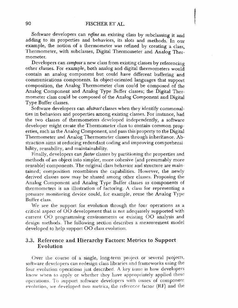
Figure 4. Evolving components. Development of software components involves an evolutionary cycle of subprocesses.
Abstraction
Factorizatio Composition
Refinement
books may ... cause the analyst to miss reuse opportunities and make the model more difficult to change" (p. 184, italics added).
Opdyke and Johnson (1989) discussed many evolutionary changes that are common in the development of 00 application frameworks. Opdyke and Johnson noted that "object-oriented software is harder to change than it should be" because many of the changes involve "changing the abstractions embodied in existing object classes and the relationships among those classes" (p. 146). Some of these common changes, which are tedious, difficult, and/or error prone in 00 environments, include creating an abstract class for one or more existing classes; changing an existing relation between objects from an inheritance (generalization/specialization) to an aggregation (component); and moving a class from one inheritance hierarchy to another.
As these observations illustrate, current 00 environments support evolution through refinement but fall short in their support for many other evolutionary processes. There is a need for a better understanding of the processes involved in evolution and tools to better support these processes.
3.2. Beyond Object Orientation
Our model of 00 development (Figure 1) emphasizes the importance of component evolution across multiple projects. In our experience, components evolve through four key processes: refinement, composition, abstraction, and factorization. These are illustrated as an ongoing cycle in Figure 4 and are explained next.
90 FISCHER ET AL.
Software developers can refine an existing class by sub classing it and adding to its properties and behaviors, its slots and methods. In our example, the notion of a thermometer was refined by creating a class, Thermometer, with subclasses, Digital Thermometer and Analog Thermometer.
Developers can compose a new class from existing classes by referencing other classes. For example, both analog and digital thermometers would contain an analog component but could have different buffering and communications components. In object-oriented languages that support composition, the Analog Thermometer class could be composed of the Analog Component and Analog Type Buffer classes; the Digital Thermometer class could be composed of the Analog Component and Digital Type Buffer classes.
Software developers can abstract classes when they identify commonalties in behaviors and properties among existing classes. For instance, had the two classes of thermometers developed independently, a software developer might create the Thermometer class to contain common properties, such as the Analog Component, and pass this property to the Digital Thermometer and Analog Thermometer classes through inheritance. Abstraction aims at reducing redundant coding and improving comprehensibility, reusability, and maintainability.
Finally, developers can factor classes by partitioning the properties and methods of an object into simpler, more cohesive (and presumably more reusable) components. The original class behavior and structure are maintained; composition recombines the capabilities. However, the newly derived classes now may be shared among other classes. Proposing the Analog Component and Analog Type Buffer classes as components of thermometers is an illustration of factoring. A class for representing a pressure monitoring device could, for example, reuse the Analog Type Buffer class.
We see the support for evolution through the four operations as a critical aspect of 00 development that is not adequately supported with current 00 programming environments or existing 00 analysis and design methods. The following section describes a measurement model developed to help support 00 class evolution.
3.3. Reference and Hierarchy Factors: Metrics to Support Evolution
Over the course of a single, long-term project or several projects, software developers can redesign class libraries and frameworks using the four evolution operations just described. A key issue is how developers know when to apply or whether they have appropriately applied these operations. To support software developers with issues of component evolution, we developed two metrics, the reference factor (RF) and the
, ;
OBJECT-ORIENTED TECHNOLOGY 91
hierarchy factor (HF), described in the next paragraph. Roughly, these metrics can classify object classes according to their appropriateness as library or application components. Library components correspond to supporting domains (discussed in Section 5.2). A class library is a repository for abstract classes that provides high reusability across multiple application domains. Application components correspond to dominant domains (discussed in Section 5.2). Applications consist largely of concrete, instance-level objects and can form a basis for reuse by being placed in a catalog of examples.
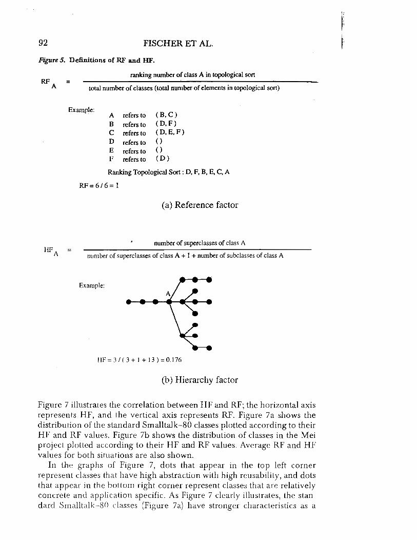
To support software developers in producing and evolving the two types of object repositories-class library and application catalog-we developed two metrics and constructed a tool that analyzes objects under development. RF measures the degree of composition and decomposition, and HF measures the degree of refinement and abstraction. Figure 5 presents definitions and examples of RF and HF. The values of RF and HF range from 0 to 1. Low RF and HF values indicate that the classes have library-like characteristics with high reusability and should be stored in a class library; high RF and HF values indicate that the classes have application-specific characteristics and should be stored in a catalog as specific examples.
RF is defined in terms of the total number of classes in reference paths and the rank order of a class in the partially ordered reference sequence (see Figure 5a). Composition and decomposition are interdependent; if a class is better modularized, more classes will use it. Also, better decomposition can be achieved when similar structures or behaviors are found in a large number of classes. Both composition and decomposition deal with "has-a" or "part-of' relations, which represent the reference structure. The metrics for composition and decomposition are quantified from this class reference structure. The value of RF is between 0 and 1 and becomes smaller when the class is referenced by many classes but does not reference other classes.
HF is a metric for the refinement and abstraction of a class and is defined in terms of the number of its superclasses and subclasses (see Figure 5b). Refinement and abstraction are interdependent; the better a class is abstracted, the easier it is to refine to a concrete class. Both refinement and abstraction deal with "is-a" and "is-kind-of" relations, which represent the class hierarchy. The metrics for refinement and abstraction are quantified from this class hierarchy. The value of HF is between 0 and 1 and becomes smaller as the class becomes more abstract.
A tool was built that graphically presents the results of applying the metrics to Smalltalk-80 classes (Goldberg, 1984). The metrics were also applied to the project for developing a CASE tool (Mei) in the Smalltalk-80 environment, discussed earlier (Aoki, 1992). Figure 6 shows the results of applying the metrics to the principal classes of Smalltalk-80-HFs, RFs, rank orders of topological sort, and names of classes that refer each class.
92 FISCHER ET AL.
Figure 5. Definitions of RF and HF.
RFA
HFA
ranking number of class A in topological sort =
total number of classes (total number of elements in topological sort)
Example: A refers to (B,C)
=
B refers to (D,F) C refers to (D, E,F) D refers to ()
E refers to ()
F refers to (D)
Ranking Topological Sort: D, F, B. E, C. A
RF=6/6= 1
(a) Reference factor
number of superclasses of class A
number of superclasses of class A + I + number of subclasses of class A
Example:
HF = 3 / (3 + 1+ 13) = 0.176
(b) Hierarchy factor
Figure 7 illustrates the correlation between HF and RF; the horizontal axis represents HF, and the vertical axis represents RF. Figure 7a shows the distribution of the standard Smalltalk-80 classes plotted according to their HF and RF values. Figure 7b shows the distribution of classes in the Mei project plotted according to their HF and RF values. Average RF and HF values for both situations are also shown.
In the graphs of Figure 7, dots that appear in the top left corner represent classes that have high abstraction with high reusability, and dots that appear in the bottom right corner represent classes that are relatively concrete and application specific. As Figure 7 clearly illustrates, the standard Smalltalk-80 classes (Fif,'llre 7a) have stronger characteristics as a

OBJECT-ORIENTED TECHNOLOGY 93
Figure 6. HF and RF values of principal classes provided in Smalltalk-80.
Class Name HF RF Sequence Referred to by
Array 0.571 0.000 0 BitBit 0.100 0.649 218 _ Form, Pen ByteString 0.833 0.003 I Character CodeController 0.700 0.631 212 Character, Cursor, Explainer, ReadStream, String CodeView 0.600 0.634 213 CodeControlled Collection 0.027 0.312 105 Bag, OrderedCollection, Set, Sorted Collection Dictionary 0.300 0.152 51 Association, Bag, Cursor, OrderedColiection Object 0.000 0.997 335 Array, Association, Browser, Context Point 0.750 0.045 15 Array, Cursor, Form, OrderedColiection Rectangle 0.250 0.042 14 Array, Cursor, Form, OrderedColiection SystemDictionary 0.800 0.860 229 Array, Association, Browser, BrowserView View 0.038 0.994 334 Controller, DisplayScreen, Form, Inspector
Figure 7. Comparison between the results of applying metrics.
j RF
j
• Abstraction HF Refinement ..
0
': ., " . ,
Average HF = 0.552 Average RF = 0.288
(a) Classes in Smalltalk-80 Library
• Abstraction HF Refinement .. o
Average HF = 0.699 Average RF = 0.653
(b) Classes Created in Mei Project
library, whereas classes created during the Mei project have stronger characteristics as an application (Figure 7b). Classes plotted outside the shadowed area in Figure 7b are those that have been created during the Mei project and will be stored in a class library in the future because they have high-level abstraction.
Two general findings from an analysis of the Mei project data are that there are several types of object evolution paths and there are two general types of programmers. Figure 8 illustrates six types of class evolution paths that were identified. The metric values for example classes are provided in Figure G.

94 FISCHER ET AL.
Figure 8. Evolution of objects during the lifetime of the project.
Abstraction HF
Refinement
RF
c: .g Vl o
1. A (initial stage): Newly created classes usually belong to area A in Figure 8 because they have no subclasses.
2. A to B: Classes such as Array, ByteString, and Point have become equipped with basic behaviors or structures and thereby are not divided into subclasses but are used by other classes. Their HFs have remained large, and their RFs have become smaller, shifting them toward area B in Figure 8. Classes in this area are basic library classes, containing well-refined concrete classes.
3. A to D: The Collection class has become equipped with abstract behaviors and a large number of subclasses created through refinement. Because the abstract class does not have its own instance variables, it does not use other classes as components, and other classes do not use it as a component. Thus, both its HF and RF have become smaller, shifting it toward area D in Figure 8.
4. A to F, D to F: The BitBlt class references other classes as components by deeply nesting them and has a high degree of abstraction. It has many subclasses, such as Pen, and reference components, such as Form and Path, which in turn further reference other objects. Thus, its HF has become smaller, and its RF has stayed relatively large. The class is regarded as an abstract application library class.

OBJECT-ORIENTED TECHNOLOGY 95
PiguTe 9. Comparison of metrics applied to programmer types.
or·----------~~----------~ HF
0 01:100 00 0 0 0 o 00 0
'/Ii~ 0 0 0 RF 0
0 8 Rf 0 00 0
0 0° o! t1I odi 0 8 8 0 0
8 100 of 0 0 0 0 0 0 0 0 0 000 0
o 0 8 ~' 0
0 P 8 0 0 o g 8 8 0 0
0 0000 0 o 0 8 00 0 ',0 0 0 <0 0 0 0 0 o 0 I 0
0 .t o~ B 9 o 0 0
8 0 0
0 g 100
0 I § 0
00
8 0 00 ~
(a) Class-Library-Developers (b) Catalog-Developers
.ri. D to E: The Object class initially had no instance variables and was a Iypical abstract class with a quite small HF and a relatively small RF, :-illch as Collection contained in D. Through the development processes, (llc abstraction of its behaviors has progressed, it has started to reference IIlany other classes as components, and its RF has become larger.
(). A to C: Classes such as SystemDictionary, Code Controller, and Code View were application-specific complex objects with a high degree or rdinement and composition. Their HFs have stayed very large, and Ilwir RFs have gotten larger, shifting to area C.
I n addition to plotting these evolution paths, we plotted the classes in Figure 7b using different colors (not shown) for the different project 1I}(~rnbers authoring the classes. This analysis identified that each project Illcmber has typical patterns in creating and evolving classes. Project IIwrnbers were divided into two main types-class-library developers and c;tI alog developers. Figure 9 illustrates the two types.
(~lasses created by class-library developers include many abstract cLt:-i:-iCS (Figure gal. The project members in this group were interested in Ill()dcls, paradigms, methodologies, and theories and were good at creatillg highly abstract meta-level systems. They were more interested in (J(~aling classes for a general library than in creating classes specific to a p;1l1 icular problem domain. Classes developed by catalog developers (FigIII (. ()b), in contrast, were mainly concrete classes. The members in this gll)1I P were interested in styles, modes, and look-and-feel paradigms. They \Vnc interested in creating several application examples using class librarIt'\ ;IfJd in improving and expanding basic classes created by others.

96 FISCHER ET AL.
This early analysis of the metrics tool suggests that the metrics can be used to distinguish library from application-specific classes, to plot the evolution of classes over time, and to distinguish library-component developers from application-component developers.
4. REUSE AND REDESIGN
One of the biggest claims of 00 proponents is that 00 components and systems are highly reusable (see Figure 3). The promise of rellse is that we can achieve "plug-compatible" systems, reduced development time, and improved quality. Current 00 programming languages, such as Smalltalk, provide a library of reusable classes that can drastically reduce programming time. In addition, off-the-shelf 00 frameworks can be purchased that support 00 design and programming in particular problem domains. Specific features of 00 languages also promote reusability, albeit at a lower level of detail {Stefik & Bobrow, 1986}. Inheritance makes it possible for a subclass to share, or reuse, methods and variables defined in its superclass. Polymorphism makes it possible for objects of different classes to respond to the same message. Being able to send the same message to objects of different classes means that a given class will be usable in several different contexts. Meyer (1987) argued that 00 design promotes reuse because the categories of objects with which the system deals are relatively stable, even though the functionality required may change over time. Thus, in a system whose organization is based on objects, a change in functionality will not necessitate a major reorganization of the software, as it might in a system based on functional decomposition. Typically, any changes will be localized to a few classes.
4.1. Where Current 00 Technology Falls Short
An analogy can be made between software-component reuse in a high-functionality programming environment and hardware-component reuse in a large hardware store. One study investigated a large hardware store with more than 300,000 "components" (Fischer & Reeves, 1992). The store provides customer assistance for locating items in the following manner. As customers enter the store, they are helped by floor managers, who direct them to specialty aisles; once in a particular area, the customers are aided by specialty assistants. For example, plumbing supplies are attended by assistants experienced as plumbers. Managers and assistants, through background knowledge and experience, are able to anticipate and support customers in defining problems and working out solutions. The components themselves are part of the problem-solving effort, with customers and assistants using them in positive and negative deictic references. Problems are solved through cooperative refinement by the application of problem- and domain-specific knowledge and plans and
OBJECT-ORIENTED TECHNOLOGY 97
through the media of the components involved. Potentially, this cooperation can be established between a problem solver and a computer system.
The strategy of employing specialized-domain experts (e.g., in plumbing or lighting in the hardware store) is successful for several reasons: The experts provide location support and are able to help customers find the right item{s); the experts provide comprehension support and allow the customers to focus on describing their problems, and then the experts provide and explain the solution; and this focus on the problem and communication with the assistants reduces the likelihood that a customer will be overwhelmed by the abundance of available items. This is a very different strategy than that employed by other high-volume stores, in which there is an abundance of "components" and only limited support for locating and understanding which components are needed for the task at hand.
Other researchers have studied reuse in high-functionality systems. Smalltalk-80, for example, has 670 classes and more than 6,000 methods. Empirical studies (Draper, 1984; Fischer, 1987; Nielsen & Richards, 1989) have shown that developers do not exploit the power of such highfunctionality systems. Lange and Moher (1989) performed an intensive I-week field study of a professional software engineer with considerable experience in 00 development. Lange and Moher found that the engineer's dominant reuse strategies were to reuse by inheritance and to reuse by copying source code from a sibling class as a template. The engineer was very familiar with the class library and consequently was often able to recall the name of a particular class a priori and locate it in the hierarchy easily. However, even when the engineer could name a class a priori, she did not often remember method names, leading to a more ad hoc search within classes for reusable methods. The researchers also observed "comprehension avoidance" strategies in which the engineer tried to avoid getting into the details of methods and instead tried to modify and test methods to assess their reusability for her task.
Despite the promise of reuse in 00 development, systematic reuse on a large scale is not being realized (Krueger, 1992). Part of the problem is that the existence of high functionality (i.e., reusable components) does not guarantee the use of that high functionality. This may be because developers do not know what reusable components exist, how to access them, how to understand them, and/or how to combine, adapt, and modify them to meet current needs (Fischer, 1987). Current 00 programming languages provide only simple tools, such as Smalltalk's Class Hierarchy Browser (Goldberg & Robson, 1983), for locating reusable classes and methods. As Nierstrasz, Gibbs, and Tsichritzis (1992) noted, "effective reuse of software presupposes the existence of tools to support the organization and retrieval of components according to application requirements, and the interactive construction of running applications from components" (p. 160).
98 FISCHER ET AL.
Another problem is that current 00 analysis and design methods do not adequately support reuse within the software development process. The reuse process involves two steps-composing new systems from existing components and developing components that can be reused in future systems. However, the current 00 methods often assume that new systems are developed from scratch (Nierstrasz et al., 1992), and reuse happens sometime during implementation. Although some 00 researchers (e.g., Johnson & Foote, 1988) have emphasized that classes must be designed for reuse and offer guidelines to promote reusability, none of the popular 00 methods has emphasized this point. Reuse is not something "tacked on" at the end of software development; it must be integrated throughout the evolutionary development process (Fischer & Girgensohn, 1990).
4.2. Beyond Object Orientation
Reuse and redesign are key aspects of our model of 00 development (Figure 1). The observations of the preceding section illustrate several difficulties with respect to reuse. First, locating reusable components in a high-functionality environment (computer based or not) can be challenging, even when the user is familiar with much of the existing functionality. Retrieval mechanisms that demand that the name of the component and/or its place in the class hierarchy be known a priori are insufficient for the location task. Second, users are reluctant to invest the time to thoroughly understand components after they are located. In the hardware example, the store assistants provided a buffer for the customer. Customers could talk about the desired functionality (in problem-oriented terms)' and assistants would provide a component or alternative components that could meet the need. In Lange and Moher's (1989) study, the engineer did not attempt to understand everything that the component did and how it accomplished tasks. Instead, she ran various tests on the component to see if it would perform the needed functionality. Third, as components are reused, they are often modified (redesigned), which leads to further component evolution. But, as described earlier, many types of modification are not eaSily supported in existing 00 environments. These three aspects of reuse and redesign-location, comprehension, and modification-are illustrated in Figure 10 (Biggerstaff & Richter, 1987; Fischer, Henninger, & Redmiles, 1991).
The reuse-and-redesign model in Figure 10 applies to various kinds of software components or artifacts, such as subroutines in a structured programming environment, classes in an 00 environment, and/or existing design examples. In some of our studies, we explored the reuse of examples of previous design solutions (Fischer et al., 1991). After finding a potentially useful example, a software developer is expected to explore

OBJECT-ORIENTED TECHNOLOGY 99
Figure 10. Reuse and redesign of components. Reuse and redesign require a software developer to locate components relevant to a tasl4 comprehend them with respect to relevance and modifiability, and, in some cases, modify the located components. These stages are intertwined, each providing feedback to the others: Comprehension may lead directly to further retrieval, and modification may require further comprehension or additional retrieval.
(deSigner/~ problem solver)
I I fo~ul_ initial design goals \.. and InItiates component search
(software components ,,~ Location retrieved or redesigned)
reformulates design goals and component needs
Modification
explores components through explanation
reformulates design goals and component needs
~re..:..v.;..;ir-ew __ sl:;;,..c;...;.o:.;;.n;.;;:ti __ nu;.;;:e..:..s_---l. Comprehension exp oratIOn, study, tutoring
extracts/applies/augments components
it more carefully to build an analogy between the example task and the current task or design goals. The location-com prehension-modification cycle would be applied to a catalog of completed projects and not just to the classes implemented on one project. For instance, a software developer might study the temperature sensing system as an example to develop a system to monitor pressure. A hypothesis is that the designer learns by analogy (from the example) how to develop a system for the current task. The model of Figure 10 helps identify where in the reuse-and-redesign process tools can add support to software developers.
Current 00 environments provide little support for these reuse processes. What is needed is an approach analogous to that of the highfunctionality hardware store described earlier-tools more explicitly support the problems of location, comprehension, and modification (Neighbors, 1984; Prieto-Diaz, 1991; Rosson, Carroll, & Sweeney, 1991). The next section discusses Explainer, a tool that speCifically supports the comprehension of reusable objects.
100 FISCHER ET AL.
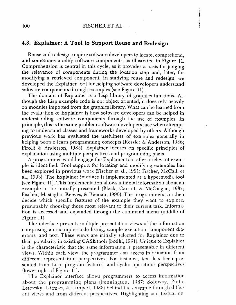
4.3. Explainer: A Tool to Support Reuse and Redesign
Reuse and redesign require software developers to locate, comprehend, and sometimes modify software components, as illustrated in Figure 1 L Comprehension is central in this cycle, as it provides a basis for judging the relevance of components during the location step and, later, for modifying a retrieved component In studying reuse and redesign, we developed the Explainer tool for helping software developers understand software components through examples (see Figure 11).
The domain of Explainer is a Lisp library of graphics functions. Although the Lisp example code is not object oriented, it does rely heavily on modules imported from the graphics library. What can be learned from the evaluation of Explainer is how software developers can be helped in understanding software components through the use of examples. In principle, this is the same problem software developers face when attempting to understand classes and frameworks developed by others. Although previous work has evaluated the usefulness of examples generally in helping people learn programming concepts (Kessler & Anderson, 1986; Pirolli & Anderson, 1985), Explainer focuses on specific principles of explanation using multiple perspectives and programming plans.
A programmer would engage the Explainer tool after a relevant example is identified. Tool support for locating and modifying examples has been explored in previous work (Fischer et aI., 1991; Fischer, McCall, et aI., 1993). The Explainer interface is implemented as a hypermedia tool (see Figure 11). This implementation allows minimal information about an example to be initially presented (Black, Carroll, & McGuigan, 1987; Fischer, Mastaglio, Reeves, & Rieman, 1990). The programmers can then decide which specific features of the example they want to explore, presumably choosing those most relevant to their current task. Information is accessed and expanded through the command menu (middle of Figure 11).
The interface presents multiple presentation views of the information comprising an example-code listing, sample execution, component diagrams, and text. These views are initially selected for Explainer due to their popularity in existing CASE tools (Sodhi, 1991). Unique to Explainer is the characteristic that the same information is presentable in different views. Within each view, the programmer can access information from different representation perspectives. For instance, text has been presented from Lisp, program features, and cyclic operations perspectives (lower right of Figure 11).
The Explainer interface allows programmers to access information about the programming plans (Pennington, 1987; Soloway, Pinto, Letovsky, Littman, & Lampert, 1988) behind the example through different views and from different perspectives. Highlighting and textual de-

Figure 17. Comprehension of software components. The screen shows the actual state of the Explainer mterface at the end of one programmer's test session. The interface is based on the principle of making examples accessible through multiple presentation views (e.g., code, sample output, text, and diagram) and multiple representation perspectives (e.g., Lisp, program features, and, in this example, cyclic group operations). The hypertext interface allows information to be accessed through selection and use of the command menu (bottom left of screen).
Explainer
III
( x -at.t.ochnent ) ) « n u ll t het o!t -ll!lt> nil ) ( ~eto ~ ( t rad i u s {cos ( - theta pi / 2»)
y ( * radiu~ ( ~ i n ( - thet~ p ;~2» ) ( 9roph;cs : dro~-~tr 'n9 · x ·
ot.tachnent-x center attachnent-v center )
atWi"';'Wi·IWliiWliMIWW.,ml
I
I
I
ecord1ng
15USJEcl: a circle A. Highlight D. Diagram E. Text How F. Text Why G. Text Swry
~ ••• (""0".)
~ •• • (I ... )
f •• , (Mr.)
(I ... s)
v isualization of addition nodulo 199 ... ,
•

102 FISCHER ET AL.
Figure 12. Clock task as described to programmer subjects.
Write a program to draw a clock face (without the hands) that shows the hour numerals. 1 - 12. Your solution should look like the picture below.
scriptions allow programmers to understand the relations between elements of programming plans and system components. This specific information enabled the test programmer to identify the Lisp function called to draw the label, the assignment function that calculated the position, and the variables on which the position calculation depended. The programmer could then apply the same functions in a solution to a new task.
The empirical evaluation of Explainer tested three conditions under which subjects solved the programming task of drawing a clock face (see Figure 12). In all three conditions, programmers were given the same example-a program illustrating operations in a cyclic group (see Figure 11). The conditions varied the programming tool that the three groups of subjects worked with to help them understand the example. In the first condition, subjects worked with the Explainer tool as described earlier. In the second condition, subjects also worked with the Explainer tool, but the interactive menu was deactivated (the example information was fully expanded when subjects began the test). In the third condition, subjects worked with a commercially available, searchable on-line manual that contained descriptions of all the functions used in the example. The purpose of the second, intermediary condition was to determine if only the difference in information content between Explainer and the on-line manual affected the results.
The evaluation measured the performance of programmers with respect to variability in two senses. First, the notion of "directness" was defined as the number of different variations programmers would try in solving a task. The rationale was that the more support the programmers had from the example and tool in solving the task, the lower the number of trial-and-error variations. The observed measures are defined shortly, and these are compared across groups. Second, within each group, the variance in the observed measures is calculated and is then compared across groups. The rationale with this test was that the more support the example-and-tool combination provided, the more uniform (smaller variance) the programmers' behavior as measured would be within a condition.
L f:

OBJECT-ORIENTED TECHNOLOGY 103
Eight subjects were tested for each condition and were randomly assigned to conditions. The subjects all had roughly the same background knowledge in Lisp programming (being recruited from master's-level artificial intelligence courses in computer science) and little familiarity with the graphics functions required by the task.
Detailed values and comparisons of the results are available elsewhere (Redmiles, 1992). We present a brief summary of the results here. As a group, the subjects using Explainer performed the programming task more directly and with less intersubject variability than the subjects using the on-line documentation tool. The latter group proceeded in a trial-anderror fashion and, not surprisingly, exhibited great intersubject variability. It is important to note that the reduction in variance was not at the cost of performance. The "better" values for the various measures were similar across conditions-good performers were about the same in all conditions. The reduction in variance derives from the "worse" values coming closer to the "better" in the condition that used the Explainer tool-otherwise, poor performers were helped by Explainer.
The variability of the programmers' performance in the on-line documentation group is consistent with other studies of programmers (see the survey by Egan, 1991). Furthermore, the provision of an example by itself was insufficient to prevent this variability, also observed by Kessler and Anderson (1986) and noted earlier here. However, the provision of an example-supplemented by information constituting a representation of a programming plan and with a means of exploring the relation of the programming plan to a specific example solution-did stem the variability. Programmers who needed to compensate for variation in background knowledge, skill, or other predispositions were supported by the Explainer tool and approach.
The kind of support that the Explainer tool provides is critical to supporting software reuse and redesign. Increasingly, software developers are called upon to apply software components they did not author. Comprehension tools support collaboration between developers who never meet.
5. DOMAIN ORIENTATION
The third claim of 00 technology that we examine in this article is that 00 systems are understandable (see Figure 3). This claim is well motivated on the surface. The metaphor of communicating objects is a powerful one (Rosson & Alpert, 1990) that exploits our "natural" tendency to anthropomorphize (Wirfs-Brock, Wilkerson, & Wiener, 1990) and to categorize things into generalization structures. The understandability claim assumes that it is "natural" for developers and users (who are experts in the problem domain) to thi~k in 00 terms (at least as compared to more traditional structured languages). In other words, it should be natural for

104 FISCHER ET AL.
developers and users to map their "worlds" into autonomous, communicating objects with data and behavior and into generalization or inheritance structures. This implies a clearer relation between the problem and the solution and improved communication between users and developers.
The first implication is realized if the computational structures in the solution directly model problem domain concepts, so that the resulting system structures· more closely correspond to those of the problem domain. This correspondence between the structure of the problem and that of the solution reduces the conceptual distance between a developer's mental model of the problem and his or her mental model of the solution (Rosson & Alpert, 1990). This has been referred to as the "seamless" integration of analysis, design, and implementation (Henderson-Sellers, 1992), which supports human problem-domain communication (Fischer & Lemke, 1988).
The second implication results from the first. A closer mapping for the designer between problem and solution should also reduce the conceptual distance between the users' and the developers' mental models of the problem. Objects in the problem domain will have computational counterparts in the solution (Fischer, 1987). This correspondence should improve the communication between users and developers and presumably promote the development of systems that meet the users' needs.
5.1. Where Current 00 Technology Falls Short
Some of the authors of this article have been involved in teaching the 00 approach for many years. In one graduate-level course on 00 development, students are required to analyze, design, and implement a small system in Small talk/V Windows (Digitalk, Inc., 1991). One semester, the project was a shopping system for a gourmet food shop. None of the students had any previous experience with 00 methods or programming languages, although most had some previous analysis, design, and/or programming experience (primarily COBOL). The students were given a textual deSCription of the problem and requirements of the system to be developed. ReqUirements included (among other things) that customers be able to browse items in the store and make purchases based on previous purchases, pre specified recipes and/or menus, and personalized shopping lists.
Several techniques were used to gain insights into the students' progress during the semester:
1. Anonymous journals were turned in biweekly, so that students could ask questions, make comments and suggestions, and vent frustrations without fear of reprisal.
2. Students were able (but not forced) to present/discuss their progress-to-date, which often led to intense class discussions of various design issues and implications.

OBJECT-ORIENTED TECHNOLOGY 105
3. Lab sessions were provided in which students worked through a tutorial and were able to explore the Smalltalk systems with assistance from classmates and teaching assistants.
4. In their final project reports, the students were required to reflect on their learning experience.
From these sources and an examination of their design diagrams and code, several observations were made.
The students varied considerably in terms of which abstractions they viewed as "essential." The only classes agreed on by all students were Customer, Item, and Menu. There was a great deal of variability in the number and labels for other classes (although there were many other "things" described in the requirements specification). In addition, the generalization (inheritance) structures that were identified varied considerably. Some students did not specialize or generalize the Item class at all; others created two subclasses, Food and Nonfood; others had several layers of subclasses below Item; and still others conceptualized Item and Service (e.g., recycling, cooking classes/tips) as subclasses of an abstract class, Product. There was some confusion over whether a shopping cart should be included as a class (to model the purchase-inprogress) and, if so, if this was separate from the abstraction of a purchase. In general, even though the domain was familiar to all students, it was difficult in many cases for them to identify what abstractions were relevant to the problem and whether or to what extent they should be generalized or specialized. This implies two problems-a vocabulary problem in naming concepts and a conceptualization problem whereby different analyses of the problem led to different solution frameworks.
Other researchers have investigated and commented on these vocabulary and conceptualization problems (e.g., Furnas, Landauer, Gomez, & Dumais, 1987). These problems reflect difficulties in modeling and communication, which are not resolved simply by adopting an 00 approach. There are many 00 analysis and design methods that mention the problem of finding the objects in a domain (Monarchi & Puhr, 1992). Some methods provide weak, overly simplistic guidelines such as "Pick the nouns" in the problem description (e.g., Booch, 1991; Rumbaugh, Blaha, Premerlani, Eddy, & Lorensen, 1991; Wirfs-Brock et al., 1990). Other methods provide slightly more help by suggesting a look at devices, things, events, roles, sites, organizational units, and so forth (e.g., eoad & Yourdon, 1991; Shlaer & Mellor, 1988). More recently, techniques such as use cases Oacobson, Christerson, Johnsson, & Overgaard, 1992} and scripts (Rubin & Goldberg, 1992) have been suggested to help structure the developer/analyst's thinking about the problem, which in turn should facilitate identification of objects, but further research in this area is still necessary.

106 FISCHER ET AL.
These observations highlight several problems underlying the claim: that 00 is understandable or natural. First, the mapping from problem to solution is not yet seamless. Although the mapping from problem to solution is smoother in 00 development than in structured development, not all 00 structures identified in the problem have a one-to-one correspondence in the solution (Henderson-Sellers, 1992). For example, generalization relations, such as the fact that a car is a kind of automobile, can be directly mapped into a Car subclass. which inherits structure and behavior from its superclass, Automobile. However, aggregation (partwhole or composition) relations, such as the fact that an engine is a part of a car, are not as directly implementable. The semantics of part-whole relations (e.g., the fact that, if the car moves, its parts move also) must be implemented by the developer, whereas the semantics of generalization relations are built in though inheritance. Thus, although 00 development does improve the smoothness of transitioning from analysis to design to implementation, there is not always a one-to-one relation between problem and solution.
This leads to a second limitation of the understandability claim-users and developers might both be thinking in terms of objects but not in terms of the same objects. Not all objects that the users conceptualize in the problem domain will necessarily be objects in the solution, and there will likely be other objects added to the solution that users do not see as relevant to their problem. Even if we assume that the users and developers can agree on the key abstractions or objects in the users' domain (in other words, we reduce the gap between their mental models of the problem domain to an "acceptable" level), there still needs to be a transition from the problem domain model to the solution.
A third limitation is that it is not necessarily easy to find the "right" abstractions or object in a given domain. Reading various 00 analysis and design methodology texts tends to lead one to assume that recognizing or identifying the appropriate objects in a domain is straightforward-that the objects are "just there for the picking" (Meyer, 1989). In our experience, identifying the "right" abstractions for a domain can be the most difficult part of development.
5.2. Beyond Object Orientation
In a conventional (domain-independent) software environment, developers starting a new project typically have to work with low-level programming constructs and methodologies. This forces them to focus on the raw material to implement a solution rather than to try to understand the problem. This contrast has been characterized as a mismatch between the system model provided by the software environment and the situation model of the software developer (Fischer, 1987; Pennington, 1987; van Dijk & Kintsch, 1983). We have studied domain orientation in a software
'I
OBJECT-ORIENTED TECHNOLOGY 107
environment to bridge this gap by allowing domain-oriented concepts to evolve and thus allow developers to focus on abstractions in their problem domain and not on programming language concepts. We call the class of software environments that support problem-domain communication domain-oriented design environments, and we have studied the application of these environments in several domains (Fischer, 1994; Fischer et al., 1991; Lemke & Fischer, 1990). Each of these environments relies on a domain model.
A domain model is generally recognized in software engineering as the end product of a domain analysis' process that is either "synthetic" or "evidentiary" (Prieto-Diaz, 1987). In synthetic domain analysis, a software developer starts with an informal description of one or more systems within an application domain, identifies aspects common across the systems, and models these with object classes and frameworks. In evidentiary domain analysis, a software developer starts with existing systems and attempts to identify common components through reverse engineering or "design recovery" (Biggerstaff, 1989). Our model portrays domain analysis as a combination of these two processes by emphasizing the aspect of evolution. In our model, evolution corresponds to the belief that domains are open-ended; future needs cannot be completely anticipated, and some problems are by nature ill-structured and require trial-and-error exploration (Rittel, 1984; Simon, 1981). In the example, some classes and methods were postulated based on Project A in Figure 1. The new requirement in Project B to accommodate a different kind of thermometer resulted in a redesign of the domain model, and a Thermometer superclass was introduced to capture the commonalties between the Digital Thermometer and Analog Thermometer classes.
In a software development project, developers may separate components into different domains; any single project may involve components from several domains. Some of the components are project specific; they belong to the primary or dominant domain. Others are project independent; they belong to supporting domains. Supporting domains can be valid application (dominant) domains in their own right. The distinction is that they can also be used in constructing systems from different dominant domains. These domains form a hierarchy in which components from higher domains can be implemented using components from lower domains. The basic concepts behind domain separation have been expressed as domain networks (Arango, 1988) and horizontal versus vertical domains. Figure 13 illustrates a separation of dominant and supporting domains for the temperature sensing example. In this project, all the classes and frameworks could be classified as dealing with this temperature sensing. However, as related projects are implemented, classes begin to develop to support different kinds of thermometers, potentially different sensor interfaces, and communications among the thermometers, sensors, and host devices.

108 FISCHER ET AL.
Figure 13. Dominant and supporting domains in projects. Any single software development project may involve several domains. As they develop domain models, software developers must separate components. This separation leads to dOminant domains that are identified with the statement of a project (e.g., temperature sensing) and supporting domains that are reusable in multiple projects. For example, some installations have a command in Unix that samples an outside thermometer; the basic framework is the same as for sensing temperatures in furnaces.
Supporting (Horizontal)
Domains
Dominant (Vertical) Domains
Remote UNIX Temperature Weather
Sensing Command
Remote Pressure Sensing
Thermometer
Sensor
Communications
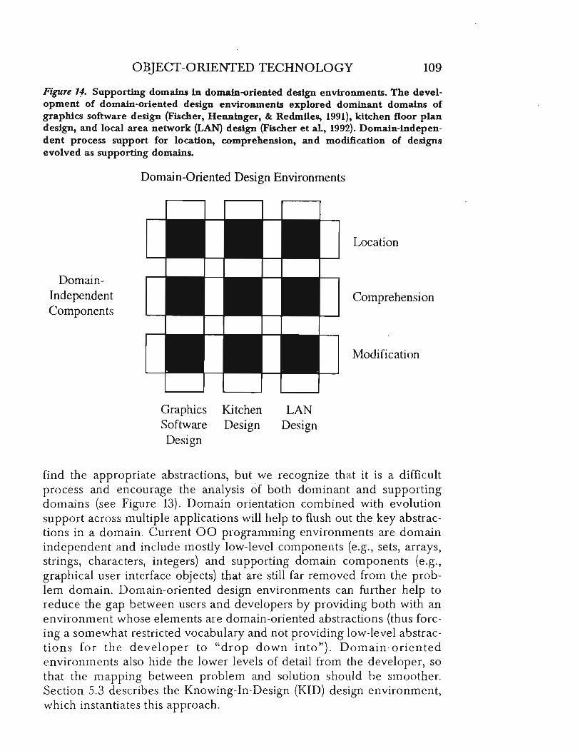
The creation of a domain-oriented software environment is, of course, also a software development project. We have developed such environments for several dominant domains, including graphics software design, kitchen floor plan design, and local area network design. In so doing, we identified frameworks and classes in supporting domains, including mechanisms for locating, comprehending, and modifying design components and knowledge.
This adds another dimension to the concept of dominant and supporting domains (see Figure 14). Namely, once separated, these supporting domains are available to assist end users. For example, a tool for modifying object classes in a software design environment may be incorporated into the system for temperature sensing. End users of the system could use the capability to further modify the thermometer classes. The distinction between development environment and application project begins to fade along with the gap between system and situation models.
These observations have motivated the evolutionary model of 00 development (Figure 1) in several ways. We do not claim to know how to
OBJECT-ORIENTED TECHNOLOGY 109
Figure 11. Supporting domains in domain-oriented design environments. The development of domain-oriented design environments explored dominant domains of graphics software design (Fischer, Henninger, &. Redmiles, 1991), kitchen floor plan design, and local area network (LAN) design (Fischer et al., 1992). Domain-independent process support for location, comprehension, and modification of designs evolved as supporting domains.
DomainIndependent Components
Domain-Oriented Design Environments
Graphics Kitchen Software Design Design
LAN Design
Location
Comprehension
Modification
find the appropriate abstractions, but we recognize that it is a difficult process and encourage the analysis of both dominant and supporting domains (see Figure 13). Domain orientation combined with evolution support across multiple applications will help to flush out the key abstractions in a domain. Current 00 programming environments are domain independent and include mostly low-level components (e.g., sets, arrays, strings, characters, integers) and supporting domain components (e.g., graphical user interface objects) that are still far removed from the problem domain. Domain-oriented design environments can further help to reduce the gap between users and developers by providing both with an environment whose elements are domain-oriented abstractions (thus forcing a somewhat restricted vocabulary and not providing low-level abstractions for the developer to "drop down into"). Domain-oriented environments also hide the lower levels of detail from the developer, so that the mapping between problem and solution should be smoother. Section 5.3 describes the Knowing-In-Design (KID) design environment, which instantiates this approach.

110 FISCHER ET AL.
5.3. Knowing-In-Design: A Tool to Support Domain Orientation
During the past 5 years, we have developed and evaluated various prototype systems of domain-oriented design environments to study issues of problem-domain communication and the integration of problem framing and problem solving (Fischer et al., 1991; Fischer, McCall, & Morch, 1989; Lemke & Fischer, 1990). Design environments support users in applying domain knowledge and provide them with various feedback mechanisms. The KID design environment supports kitchen designers in the development of floor plans (Nakakoji, 1993; Nakakoji & Fischer, in press). KID consists of several subsystems. KID-Construction, shown in Figure 15, supports construction of a kitchen floor plan. The palette of KID-Construction contains domain-oriented building blocks such as sinks, stoves, and refrigerators. The designer can create a design by applying parts from this palette, which supports design by composition. The palette elements are instances of classes, and users can apply components stored in a class library without worrying about the underlying programming substrate. Another way users can create designs is through design by modification or redesign of existing catalog examples.
KID-Specification is another KID subsystem; it allows kitchen designers to specify their abstract design requirements and design intentions (see Figure 16). Designers can select answers presented in the Questions window. Such questions, answers, and associated arguments are structured based on issue-based information systems (IBIS; Conklin & Begeman, 1988) and are gradually accumulated by users through actual design tasks. The summary of currently selected answers appears in the Current SpeCification window. Each answer is accompanied by a slider that allows designers to assign a weight representing the relative importance of the answer (scale ranges from 1 to 10, with 10 indicating most importance). Further descriptions of the mechanisms can be found in Nakakoji (1993).
A unique feature of KID is its ability to deliver information relevant to users' current tasks in terms of the domain semantics. Critics (see Messages pane in Figure 15) identify potential problems in a design (Fischer, Nakakoji, Ostwald, Stahl, & Sumner, 1993). Critics' knowledge about kitchen design includes design principles based on building codes, safety standards, and functional preferences specified through KID-Specification. If a design principle or heuristic (e.g., "If you are a single-person household, you may need a simple, single-bowl sink") is violated, a critic will fire and display a critique in the Messages pane, identify a pOSSibly problematic situation, and prompt the user to reflect on it.
Another rule-based information delivery mechanism suggests catalog examples for the user to consider. KID automatically orders catalog examples according to the specified requirements in KID-Specification and presents them to users for reuse and redesign (see the Catalog window in

Figure 75. Domain orientation in KID. Building blocks (design units) are selected from the Palette and are moved to desired locations inside the Work Area. Designers can reuse and redesign complete floor plans from the Catalog. The Messages pane displays critic messages, which are triggered by design changes that violate hard or soft constraints, Users may click on critic messages or catalog entries to access additional explanations (see Figure 16). Catalog examples in the Catalog pane are automatically ordered according to the requirements of the current coristruction. These requirements are determined either by the elements in the current Work Area or issues selected in a Specification window {Figure 16).
Construction
'tltte
w411,
do on
DC] window,
,ink.,
ODD Ho ve ,
~Ielre--.l ~~~
w ! ! i i M. rk - k i tch.n
, M __ ! i
: i ~ J , I , , , , ! i ail ly-Kitch."
Ii ! I 8 Elly-Ki tch.n 111 .. m UJ
Clear Work AreA Critique All Un Oo).c " Pral,. All New Objtct C&U.log Explorer
Messagea
I [Sp .. "I., 4·'l' Sin rS.uittc, 4. '1- Sin
Critique from Spec Pra.lse from Spec
Resume Sptcif1ca tlon
R ~ Cr.«t. D.3i9" Unit Doubl .. -8o"I-SinJc ' i ~ Ifovo 00$;9" U,,;e Ooublo-8o"l-$;"k-/ I , ~
El ~ • r'loliso-l: :"how A"YUlnontat Ion :"lnyl,,-Uowl-:'lnk-l., s To Deo othc!!" cOlnlnBncl9. IlrOIl !l Shirt. Control, !loti!
Edit QIOb41 Descriptions Sa.ve: In Ca.U.log

Figure 76. Specification and explanation to support information delivery. KID provides an explanation about interdependency between a design requirement and a critic (e.g., the critic triggered in Figure 15). Argumentation and issues related to the current design can be reviewed and can be used to further specify design goals.
Specificat;ion
HILL-KITCHEN MARK-KITCHEN BILLY-KITCHEN ELL Y -KI T CHEN I SAK -KIT CHEN JONES-K! T CHEN OSCAR - Kl T CHE N ANDI-Kl TCHEN BARB-KITCHEN BOB-KITCHEN CAT HY -Kl T CHEN COLE-KITCHEN COUGER-KITCHEN D014S0N-KITCHEN DREYER-KITCHEN GEORGE-KITCHEN GONZALES-KITCHEN
1 Entert.inrlent reQuirel"lent?
Savt Current Spetl"cat lon Start New Speclf'katlon Show Suggestions Qulc~ Question
Entcctafnncnt rcgutrcncnt7 'Yu 'Occasionally 'S"ldon 'Not at all
M"thods of Cookin9
Do you usually use a rlicrowave? ·ye!5 'no
Other Kitchen Activities
Children'. Han90ut? 'ye~
'no
Do you need e eating space? 'yes 'no
2 14hich type of sink do you need?
Prt!ferences
3 I s the pr 1 nery cook right-handed or left-handed?
4 How I"'l.eny cooks usually use the kitcnen at once?
6 Si.e of fonny? 8 K 1 tchen
Specif1cet1on
Type of kitchen? ·contenporory 'Traditional -Country
Shape of kitchen? ·L-shape ·U-shape (an~uer suggested because hov-~any-coo ·Corr;dor • Isllmd (~n~uer sU9gested because enterteinnen ·One-\Jal1
Load Specific a tlons Copy SpeclnCAtlon So, Option, Quick Answer
Type: kitchen
Size of fanny? t~One
Store eaSt Issues Catalog Explorer Resume Constrvctlori Qulc .. Argument
Nane: joe-kitchen
Ho~ "any cooks usually use the kitchen at once?
2';--- one Is the prinary cook right-handed or left-handed?
''''-+- Left handed Entcrt,'nncnt rcgutrc"cntt I~Yes
Uhlch type of sink do you need?
·doublc boul sink ·Double-Boul-S1nk-Exi.ts(Jc::~hole-D"si9n)· (.) If you often entertain, a doubl" boul sink
18 preferable. (l'1ak~oJ'; I(~tyo, 18.-'12,...,1 18126148]
·single boul sink ·Sin91e-Boul-Sink-Exi.t.(Jc : :~hol.-Desi9n)·
~(.) If you have 0 .n011 fani1y. you nOy need just a single-boul .ink. [Hekek0J', f("""YOJ
ar\1Iy, you le-boul sink.
~ Sho ... Uhy SU99ut.d sln9l .-bo ... l-sln/( ~ Sho ... Rr91U'1.nts typ.-of-II
ink ~ S.l.ct 111"u. Fro.. Rr9U1'1.
nt if-you-oft.n-.nt ~ T099l. Rns .... r yu ~ .
1"';'-'
OBJECT-ORIENTED TECHNOLOGY 113
Figure 15). KID uses critiquing rules to compute the appropriateness of each catalog example and provides mechansims to describe why a particular catalog example is inferred to be appropriate to the requirements (Nakakoji, 1994).
In one study (Nakakoji, 1993), eight novices and one expert in kitchen design used KID to develop a design for a kitchen to fit the following task situation: Both husband and wife have jobs; during weekdays, the wife does most of the cooking; and, during weekends, the couple cooks meals together. Subjects were encouraged to think aloud (Ericsson & Simon, 1980) by making statements to the experimenter, and, in three trials, subjects were observed through constructive interaction (Miyake, 1986) in which they were paired to encourage verbalization. A postexperiment interview collected additional comments, and the protocols and comments were analyzed to evaluate the benefit of KID.
Overall, the study indicated that KID augmented the users' design process. The novices unanimously acknowledged that KID provided them with useful information about kitchen design, and, although the expert responded that her final design was not affected by using KID, she noted that KID made her reflect on information she might not otherwise have considered (Nakakoji & Fischer, in press). More specifically, KID supported the integration of problem framing and problem solving and the incremental understanding of a task. The unexpected appearance of critiques caused subjects to reflect on their task and to attend to the associated explanation (Figure 16). Moreover, subjects often argued against a design principle that was used to deliver information, and they modified the associated rules (arguments). Not only the delivered knowledge itself, but also the inferred relevance by the system, which provided information about dependencies between the specification and construction, helped give subjects direction in reframing their partial construction and specification.
KID demonstrates many of the goals for domain orientation presented in our model-namely, the analysis of dominant and supporting domains into abstractions that users can access in developing a new project. The classes in this domain are represented by the elements of the palette. Completed designs captured as catalog entries represent instantiations of a kitchen floor plan framework. The less obvious, supporting domains include components that can be useful across a spectrum of design domains-for example, mechanisms for supporting rule-based critics, catalog suggestion, explanation, and end user modification.
6. CONCLUSIONS
The problems software developers face in applying 00 technology can be understood only by looking beyond the technological possibilities and beyond the context of individual developers and projects. 00 technology

114 FISCHERETAL.
makes possible software e"-olution, reuse and redesign, and dom""n . • . • <U onen-
tatIOn. However, the...'€ goals cannot always be achIeved in practice. S ft-~a~e. development is . a . cooper.ative d~sign process among m:ny mdividuais and many ~as of artifacts. WIth respect to reuse and redesign, the cooperation otten spans multiple projects and individuals who never meet.
We have presented a detailed model of software development that focuses on the three aspects of evolution, reuse and redesign, and domain orientation. In its detaiL the model is based on 00 technology, but more generally it has elements of a model of long-term cooperative design. The model represents a cognitiye model by being developed from the perspective of software developers and the problems they face. We have exam. ined firsthand obseryations that have motivated the model as well as studies by other researchers.
The scale and scope of the model and the number of hypotheses in it make it difficult to e .... aluare in a conventional empirical study. In particular, no single software de...-elopment environment exists that embodies all the technical and orgarnz3.rional aspects of the model. However, evidence observed in unstructured settings and an assessment of the current state of software engineering i::1d.icate not only the heed for but a movement toward environments r1:3.t support this model.
The varied experience and prototype tools contributed by the different authors of this article ha .... e proved helpful in corroborating the model. Many specific hypotheses have been verified in prototype systems. Metrics help less theoretical developers identify good abstractions. Design examples with perspectiye explanations reduce variability of performance in sample groups. Techniques of domain orientation make software acces· sible to noncomputer professionals and make a class of problems accessi· ble to novices.
00 technology is not a "silver bullet" (Brooks, 1987) that will eliminate the "software crisis." It is an enabling technology that provides a fotlllda tion for the next generation of paradigms in support of complex computa· tion. Successes toda\' come from the talents and dedication of people practicing good desi"gn \\-ith the tools at their disposal. The model and tools we have presented push the technology in a direction that is more inclusive of people as \,'ell as of problem domains.
NOTES
Acknowledgments. \\'c thank the members of the Human-Computcr COl1ll11ll nication group at the C l1l\crsity of Colorado for their substantial contributloll" (I)
the conceptual framp\\llrk and the systems discussed in this articlc. Support. Research \\.lS supported by Colorado Advanced So(lw<tll' !1l\[1,(llk
Software Rcsrarch _-\Sslllutes, Inc. (Tokyo); National Science FOllnda(IOll (,Llll(

OBJECT-ORIENTED TECHNOLOGY 115
MDR-9253245; US West Advanced Technology (Boulder); and NYNEX Science and Technology Center.
Authors' Present Addresses. Gerhard Fischer and Kumiyo Nakakoji, Department of Computer Science, University of Colorado, Boulder, CO 80309-0430. E-mail: gerhard@sigi. cs . colorado. edu and kLnniyo@sigi. cs . colorado. edu; David Redmiles, Department of Information and Computer Science, University of California, Irvine, CA 92717-3425. E-mail: redmiles@ics. uci. edu; Lloyd Williams, Software Engineering Research, 264 Ridgeview Lane, Boulder, CO 80302. E-mail: [email protected]; Gretchen I. Puhr, Accounting and Information Systems, School of Business, University of Colorado, Boulder, CO 80309-0419. E-mail: puhr@ucsu. colorado. edu; Atsushi Aoki, Software Engineering Laboratory, Software Research Associates, Inc., Suite 502, 1113 Spruce Street, Boulder, CO 80302. E-mail: [email protected] .
He] Editorial Record. First manuscript received January 25, 1993. Revision received November 8, 1993. Accepted by Robert Rist and Thomas P. Moran. Final manuscript received August 31, 1994. - Editor
REFERENCES
ACM. (1990). Special issue on object-oriented deSign. Communications of the ACM, 33(9).
ACM. (1992). Special issue on analysiS and modeling in software development. Communications of the ACM, 35(9).
Adelson, B., & Soloway, E. (1985). The role of domain experience in software design. IEEE Transactions on Software Engineering, 11, 1351-1360.
Aoki, A. (1992). The integration process in an object oriented programming environment {Technical Report SEL-Boulder-92-l}. Tokyo: Software Research Associates, Inc.
Aoki, A. (1993). Objecto shikou shisutemo bunseki sekkei nyuumon [Introduction to object-oriented analyses and design]. Tokyo: Software Research Associates, Inc.
Arango, G. F. (1988). Domain engineeringfor software reuse (Technical Report 88-27). Irvine: University of California, Department of Information and Computer Science.
Berard, E. V. (1993). Essays on object-oriented software engineering. Englewood Cliffs, NJ: Prentice-Hall.
Biggerstaff, T. j. (1989). Design recovery for maintenance and reuse. IEEE Computer, 22(7), 36-49.
Biggerstaff, T. j., & Richter, C. (1987). Reusability framework, assessment, and directions, IEEE Software, 4(2),41-49.
Black, j. B., Carroll, j. M., & McGuigan, S. M. (1987). What kind of minimal instruction manual is the most effective? Proceedings of the CHI+GI '87 Conference on Human Factors in Computer Systems and Graphics Interface, 159-162. New York: ACM.
Booch, G. (1991). Object-oriented design with applications. Redwood City, CA: Benjamin/Cummings.

116 FISCHER ET AL.
Brooks, F. P. (1987). No silver bullet: Essence and accidents of software engineer~ ing. IEEE Computer, 20(4), 10-19.
Coad, P., & Yourdon, E. (1991). Object-oriented analysis (2nd ed.). Englewood Cliffs, NJ: Prentice-Hall.
Conklin,]., & Begeman, M. (1988). gIBIS: A hypertext tool for exploratory policy discussion. Transactions of Office Information Systems, 6, 303-331.
Curtis, B., Krasner, H., & Iscoe, N. (1988). A field study of the software design process for large systems. Communications of the ACM, 31, 1268-1287.
Deutsch, L. P. (1989). Design reuse and frameworks in the Smalltalk-80 system. In T.]. Biggerstaff & A]. Perlis (Eds.), Software reusability: Applications and experience (Vol. 2, pp. 57-72). New York: ACM.
Digitalk, Inc. (1991). SmalltalklV Windows tutorial and programming handbook. Los Angeles: Author.
Draper, S. W. (1984). The nature of expertise in UNIX. Proceedings of the INTERACT '84 IFIP Conference on Human-Computer Interaction, 182-186. Amsterdam: Elsevier.
Egan, D. E. (1991). Individual differences in human-computer interaction. In M. Helander (Ed.), Handbook of human-computer interaction {pp. 543-568}. Amsterdam: North-Holland.
Ehn, P. (1988). Work-oriented design of computer artifacts. Stockholm: Almquist & Wiksell.
Ericsson, K. A., & Simon, H. A. (1980). Verbal reports as data. Psychological Review, 87, 215-25l.
Fischer, G. (1987). Cognitive view of reuse and redeSign. IEEE Software, 4(4),60-72. Fischer, G. (1994). Domain-oriented design environments. In L. Johnson & A.
Finkelstein (Eds.), Automated software engineering (Vol. 1, pp. 177-203). Boston: Kluwer.
Fischer, G., & Girgensohn, A. (1990). End-user modifiability in design environments. Proceedings of the CHI '85 Conference on Human Factors in Computer Systems, 183-191. New York: ACM.
Fischer, G., Grudin,]., Lemke, A C., McCall, R., Ostwald, J., Reeves, B. N., & Shipman, F. (1992). Supporting indirect, collaborative design with integrated knowledge-based design environments. Human-Computer Interaction, 7,281-314.
Fischer, G., Henninger, S. R., & Redmiles, D. F. (1991). Cognitive tools for locating and comprehending software objects for reuse. Proceedings of the 73th International Conference on Software Engineering, 318-328. Los Alamitos, CA: IEEE Computer Society Press.
Fischer, G., & Lemke, A C. (1988). Construction kits and design environments: Steps toward human problem-domain communication. Human-Computer Interaction, 3, 179-222.
Fischer, G., Lemke, A. C., & Rathke, C. (1987). From design to redesign. Proceedings of the 9th International Conference on Software Engineering, 369-376. Los Alamitos, CA: IEEE Computer Society Press.
Fischer, G., Mastaglio, T., Reeves, B. N., & Rieman,J. (1990). Minimalist explanations in knowledge-based systems. Proceedings of the 23rd Hawaii International Conference on System Sciences: Vol III. Decision suj)port and knowledge based systems track, 309-'317. Los Alamitos, CA: IEEE Computer Society Press.
Fischer, G., McCall, R., & Morch, A. (1989). Design environments for constructive and argumentative design. Proceedings of the CHI '89 Conference on Human Factors
OBJECT-ORIENTED TECHNOLOGY 117
in Computer Systems, 269-275. New York: ACM. Fischer, G., McCall, R., Ostwald,j., Reeves, B., & Shipman, F. (1993). Seeding,
evolutionary growth and reseeding: Supporting incremental development of design environments. Proceedings of the CHI '94 Conference on Human Factors in Computer Systems, 292-298. New York: ACM.
Fischer, G., Nakakoji, K, Ostwald,]., Stahl, G., & Sumner, T. (1993). Embedding critics in design environments. Knowledge Engineering ReviewJourna~ 8,285-307.
Fischer, G., & Reeves, B. N. {1992}. Beyond intelligent interfaces: Exploring, analyzing and creating success models of cooperative problem solVing. Applied Intelligence, 1, 311-332.
Furnas, G. W., Landauer, T. K., Gomez, L. M., & Dumais, S. T. (1987). The vocabulary problem in human-system communication. Communications of the ACM, 30,964-971.
Goldberg, A. (1984). Smalltalk-80, the interactive programming environment. Reading, MA: Addison-Wesley.
Goldberg, A,. & Robson, D. (1983). Smalltalk-80: The language and its implementation. Reading, MA: Addison-Wesley.
Greenbaum,]., & Kyng, M. (Eds.). (1991). Design at work: Cooperative design of computer systems. Hillsdale, NJ: Lawrence Erlbaum Associates, Inc.
Henderson-Sellers, B. (1992). A book of object-oriented knowledge. Englewood Cliffs, Nj: Prentice-Hall.
Hutchins, E. (1993). Distributed cognition: A cognitive ethnography of ship navigation. San Diego: University of California, Department of Cognitive Science.
jacobson, 1., Christerson, M.,johnsson, P., & Overgaard, G. (1992). Object-oriented software engineering: A use case driven approach. Reading, MA: Addison-Wesley.
Johnson, R. E., & Foote, B. (1988). Designing reusable classes.]ournal ofObject-Oriented Programming, 1(2}, 22-35.
Kessler, C. M., & Anderson,]. R. (1986). Learning flow of control: Recursive and iterative procedures. Human-Computer Interaction, 2, 135-166.
Krueger, C. W. (1992). Software reuse. ACM Computing Surveys, 24, 131-184. Lange, B. M., & Moher, T. G. (1989}.Some strategies of reuse in an object-oriented
programming environment. Proceedings of the CHI '89 Conference on Human Factors in Computer Systems, 69-73. New York: ACM.
Lemke, A. C., & Fischer, G. (1990). A cooperative problem solving system for user interface design. Proceedings of the AAAI-90 National Conference on Artificial Intelligence, 479-484. Cambridge, MA: AAAI Press/MIT Press.
Lubars, M., Meredith, G., Potts, C., & Richter, C. (1992). Object-oriented analysis for evolving systems. Proceedings of the 74th International Conference on Software Engineering, 173-185. Melbourne: ACM
Meyer, B. (1987). Reusability: The case for object-oriented design. IEEE Software, 4(2),50-64.
Meyer, B. (1989). Object-oriented software construction. Englewood Cliffs, NJ: Prentice-Hall.
Miyake, N. (1986). Constructive interaction and the iterative process of understanding. Cognitive Science, 70, 151-177.
Monarchi, D. E., & Puhr, G. 1. (1992). A research typology for object-oriented analysis and design. Communications of the ACM, 35(9), 35-47.
Nakakoji, K. (1993). Increasing shared understanding of a des(gn task between designers

118 FISCHER ET AL.
and d.aigTi nwiTonments: The TOle of a specification component (Technical Re CU-CS-6S1-93). Unpublished PhD dissertation, University of Colorado, De p~~ ment of Computer Science, Boulder. p
Nakakoji, K {I994}. Case-deliverer: Retrieving cases relevant to the task at hand. In S. \'less, KAlthoff, & M. M. Richter (Eds.), Lecture notes in artificial intelligence (pp. 446-470). Kaiserslautem, Germany: Springer-Verlag.
Nakakoji, K, & Fischer, G. (in press). Intertwining knowledge delivery and elicitation: A process model for human-computer collaboration in design. Knowledge-Based Systems Journal.
Neighbors,]. {1984}. The Draco approach to constructing software reusable components. IEEE Transactions on Software Engineering, 10, 564-574.
Nielsen, ]., & Richards, J. T. {1989}. The experience of learning and using Smalltalk. IEEE Software, 6{5}, 73-77.
Nierstrasz, 0., Gibbs, S., & Tsichritzis, S. (1992). Component-oriented software development Communications of the ACM, 35(9}, 160-165.
Norman, D. A. (1993). Things that make us smart. Reading, MA: Addison-Wesley. Opdyke, W., & Johnson, R. (1989). Refactoring: An aid in designing application
frameworks. Proceedings of the Symposium on Object-Oriented Programming Emphasizing Practical Application, 145-160. New York: ACM.
Pennington, N. {1987}. Stimulus structures and mental representations in expert comprehension of computer programs. Cognitive Psychology, 19,295-341.
Petroski, H. (1985). To engineer is human: The role offailure in successfol deSign. New York: St. Martin's Press.
Pirolli, P., & Anderson, J. R. (1985). The role of learning from examples in the acquisition of recursive programming skills. Canadian Journal of Psychology, 39, 240-272.
Prieto-Diaz, R. (1987). Domain analysis for reusability. Proceedings of the InternationalComputer Software and Applications (COMPSAC-87) Conference, 23-29. Los Alamitos, CA: IEEE Computer SOCiety Press.
Prieto-Diaz, R. (1991). Implementing faceted classification for software reuse. Communications of the ACM, 34(5), 88-97.
Redmiles, D. F. (1992). From programming tasks to solutions: Bridging the gap through the explanation of examples. Unpublished PhD dissertation, University of Colorado, Department of Computer Science, Boulder.
Rist, R. S. (1989). Schema creation in programming. Cognitive Science, 13,389-414. Rittel, H. W. J. (1984). Second-generation design methods. In N. Cross (Ed.),
Developments in design methodology (pp. 317-327). New York: Wiley. Rosson, M. B., & Alpert, S. (1990). The cognitive consequences of object-oriented
design. Human-Computer Interaction, 5,345-379. Rosson, M. B., Carroll,J. M., & Sweeney, C. (1991). A view matcher for reusing
Smalltalk classes. Proceedings of the CHI '97 Conference on Human Factors in Computer Systems, 277-283. New York: ACM.
Rubin, K. S., & Goldberg, A. (1992). Object behavior analysiS. Communications 0/ the A CM, 35(9),48-62.
Rumbaugh, j., Blaha, M., Premerlani, W., Eddy, F., & Lorensen, yv. (1991). Object-oriented modeling and deSign. Englewood Cliffs, NJ: Prentice-Hall.
Schoen, D. A. (1983). The reflective practitioner: How profeSSionals think in action. N cw York: Basic.

OBJECT-ORIENTED TECHNOLOGY 119
Shlaer, S., & Mellor, S. (1988). Object-oriented systems analysis: Modeling the world in data. Englewood Cliffs, NJ: Prentice-Hall.
Simon, H. A. {1981}. The sciences of the artificial. Cambridge, MA: MIT Press. Sodhi, j. (1991). Software engineering methods, management, and CASE tools. BIue
Ridge Summit, PA: TAB.
Soloway, E., ~into,j., Letovsky, S., Littman.' D., & Lampert, R .. ( 1988). Designing documentation to compensate for delocahzed plans. Communtcations of the A CM 37, 1259-1267. I
Stefik, M.j., & Bobrow, D. G. (1986). Object-oriented programming: Themes and variations. AI Magazine, 6(4}, 40-62. .
Swartout, W. R., & Balzer, R. {1982}. On the inevitable intertwining of specification and implementation. Communications of the ACM, 25, 4:~8-439.
van Dijk, T. A., & Kintsch, W. (1983). Strategies of discourse comprehension. New York: Academic.
Ward, P. T., & Williams, L. G. (l990a). Domain analysis: An example (Technical Report SERM-013-90). Boulder: Software Engineering Research.
Ward, P. T., & Williams, L. G. (1990b). Domain modeling (Technical Report SERM-012-90). Boulder: Software Engineering Research.
Wirfs-Brock, R., Wilkerson, B., & Wiener, L. (1990). Designing object-oriented software. Englewood Cliffs, l\U: Prentice-Hall.
Young, S. J. (1982). Real time languages: DeSign and development. Chichester, England: Ellis Horwood.