bevarage processing
TRANSCRIPT
i | P a g e
UNIVERSITY OF DAR ES SALAAM
COLLEGE OF ENGINEERING AND TECHNOLOGY
FACULTY OF CHEMICAL AND PROCESS ENGINEERING
DEPARTMENT OF CHEMICAL AND MINING ENGINEERING
PRACTICAL REPORT
PT 2
2015/2016
COCA-COLA BEVARAGE PROCESSING
DEGREE PROGRAMME: BACHELOR OF SCIENCE IN CHEMICAL AND
PROCESS ENGINEERING
NAME OF STUDENT: MARO, ROLLAND D.
STUDENT’S REGISTRATION NUMBER: 2013-04-01965
NAME OF PT COMPANY: COCA-COLA KWANZA COMPANY LTD.
NAME OF INDUSTRIAL TRAINING OFFICER: Mr. AMUR
NAME OF ACADEMIC TUTOR/SUPERVISOR: ABRAHAM TEMU
PT DURATION: EIGHT WEEKS
ii | P a g e
Table of Contents AKNOWLEDGEMENT.................................................................................................... iii
GENERAL ABSTRACT .....................................................................................................iv
PART 1 ..........................................................................................................................v
WEEKLY REPORT............................................................................................................v
PART 2 .........................................................................................................................vi
MAIN REPORT ..............................................................................................................vi
1.0 COCA-COLA KWANZA COMPANY LTD ..................................................................1
1.1 HISTORICAL BACKGROUND OF COCA-COLA KWANZA. .......................................1
1.2 COMPANY VISION AND PURPOSE. ...................................................................2
1.2.1 Vision ............................................................................................................2
1.2.2 Purpose.........................................................................................................2
1.3 ORGANISATION STRUCTURE IN COCA-COLA KWANZA. ......................................2
2.0 SOFT DRINK MANUFACTURING. ..........................................................................3
2.1 RAW MATERIALS ..................................................................................................5
2.2 UTILITIES..............................................................................................................5
2.2.1 COMPRESSED AIR ..........................................................................................5
2.2.1 STEAM. .........................................................................................................6
2.2.3 WATER ..........................................................................................................8
2.3 SRYUP ROOM AND SYRUP PRODUCTION ............................................................. 11
2.3 BLENDING SYSTEMS (MIXER) .............................................................................. 13
2.4 PLASTIC BOTTLED BEVERAGE PRODUCTION LINE ................................................. 14
2.4.1 INJECTION PLANT......................................................................................... 14
2.4.2 BLOWING SECTION ...................................................................................... 15
2.5 FILLING SYSTEMS ............................................................................................... 17
2.5 GLASS BOTTLE BEVARAGE PRODUCTION LINES .................................................... 18
2.5.2 EMPTY BOTTLE INSPECTION (EBI).................................................................. 20
2.6 DATE CODING SYSTEMS...................................................................................... 20
2.7 PACKING SYSTEMS ............................................................................................. 20
Glass bottle beverage packing............................................................................... 20
Plastic bottle beverage packing ............................................................................. 20
CONCLUSION .............................................................................................................. 21
RECOMENDATION ....................................................................................................... 21
REFERENCE ....................................................................... Error! Bookmark not defined.

iii | P a g e
AKNOWLEDGEMENT
I would like to express my deepest appreciation to all those who provided me the
possibility to complete this report. A special gratitude I give to our industry
training officer, Mr. Amur, whose contribution in stimulating suggestions and
encouragement, helped me to coordinate my practice process in the industry and in
writing this report.
Furthermore I would also like to acknowledge with much appreciation the crucial
role of the staff of COCA-COLA Kwanza Company LTD, who gave the permission
to use all required equipment and the necessary materials to complete the learning
task Mr. Proches. A special thanks goes to my fellow student during this practical
training, Miss Haule Pendo. Last but not least, many thanks go to the supervisor of
the training, Mr. Abraham Temu whose have invested his full effort in guiding us
on what we are supposed to do and learn during the training session and this report
writing. I have to appreciate the guidance given by other supervisors as well as the
Company specialists, technicians and operators especially in our training process
that has improved our skills thanks to their comments and advices.
iv | P a g e
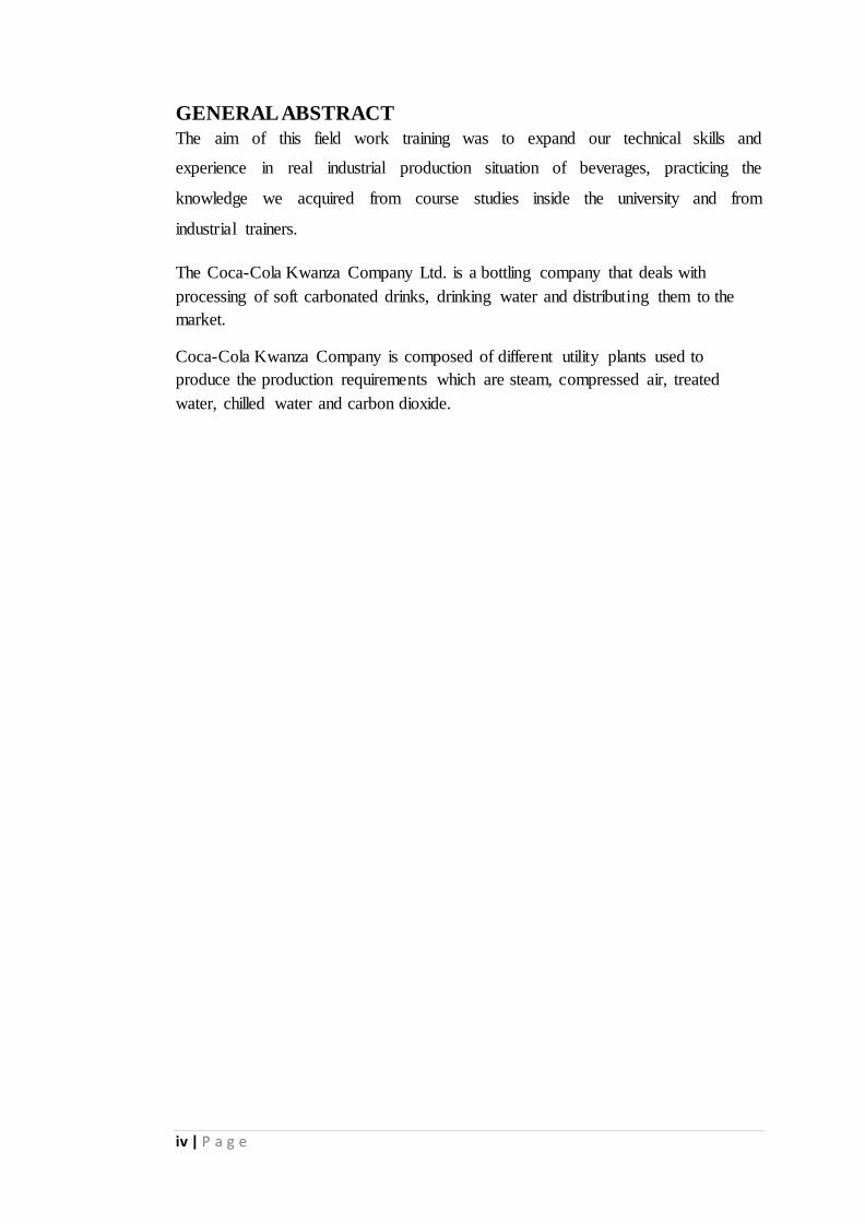
GENERAL ABSTRACT
The aim of this field work training was to expand our technical skills and
experience in real industrial production situation of beverages, practicing the
knowledge we acquired from course studies inside the university and from
industrial trainers.
The Coca-Cola Kwanza Company Ltd. is a bottling company that deals with
processing of soft carbonated drinks, drinking water and distributing them to the
market.
Coca-Cola Kwanza Company is composed of different utility plants used to
produce the production requirements which are steam, compressed air, treated
water, chilled water and carbon dioxide.

v | P a g e
PART 1
WEEKLY REPORT

vi | P a g e
PART 2
MAIN REPORT
1 | P a g e
1.0 COCA-COLA KWANZA COMPANY LTD
Coca-cola Kwanza Ltd is located in Msasani Dar Es Salaam offering services in
Dar Es Salaam. It deals with processing and bottling soft drinks and distributing
them to the local distributors.
1.1 HISTORICAL BACKGROUND OF COCA-COLA KWANZA.
The seeds of Coca-Cola Kwanza (CCK) were sown on a warm Christmas Eve in
1952, when the first Coca-Cola bottled in the east African country rolled off the
production lines.
Then called Tanganyika Bottlers, it was owned by Greek businessman Aris
Cassolis. The country gained independence in 1961 and changed its name to
Tanzania in 1964, following the union of Tanganyika and Zanzibar. Cassolis was
quick to follow suit, proudly changed his company’s name to Tanzania Bottlers.
In the decades that followed, growth was somewhat sluggish and the company
changed hands. In 1995, when Coca-Cola Sabco became the majority shareholder
in Tanzania Bottlers Ltd, the company’s name again evolved to become Kwanza
Bottlers, (meaning ‘first’ in Swahili), and later Coca-Cola Kwanza (CCK).
Exciting developments followed, including a new, ultra-modern facility in
Mikocheni in Dar-Es-Salaam. CCK also has a bottling plant in Mbeya.
CCK’s significant events and achievements include:
In 1997, its new Mikocheni plant was opened by the then Tanzanian president
Benjamin William Mkapa, who enjoyed the first bottle of Coca-Cola off the line.
In 1998, Zanzibar Bottlers won a Silver Quality Award. In 1999, Zanzibar Bottlers
received the Coca-Cola Northern Africa Division President’s Gold Award for
Quality.
In September 1999, CCK celebrated record sales, topping the list of Coca-Cola
Sabco companies. In 2002, Zanzibar received the Bronze Quality Award In 2004,
2 | P a g e
the Zanzibar Plant received a Silver Quality Award. In 2013, Mbeya received the
Bronze Quality Award.
1.2 COMPANY VISION AND PURPOSE.
1.2.1 Vision
The company wants to be best In sales volume and in return on capital employed.
Coca-Cola Bottler: A consumer driven, customer oriented, manufacturer, sales &
Distribution Company that markets the products & brands of The Coca-Cola
Company. In the World: To measure the company against the best Coca-Cola
bottlers in the World.
1.2.2 Purpose
The purpose of the company is to create value for everyone touched by its business
by providing, with passion and focus, the right refreshment, at the right price, in the
right place.
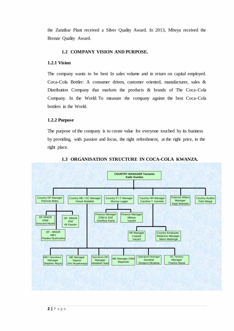
1.3 ORGANISATION STRUCTURE IN COCA-COLA KWANZA.
COUNTRY MANAGER Tanzania
Kadir Gunduz
Country DF Manager
Pancras BabuCountry ME / DC Manager
Feisal Abdallah
Country P / F Manager
Murray Loggie
Country HR Manager
Caroline T. Kavishe
Country Auditor
Felix Maagi
DF-MNGR
DSM
Innocent Mushi
DF - MNGR
MBY
Pasaka Nyamusika
DF- MNGR
ZNZ
Ali Kassim
MBY Operations
Manager
Stephen Akyoo
ME Manager
DepotsJohn Mugakanaga
ME Manager DSM
Mapendo
Operations Manager
Zanzibar
Songoro Mnukwa
Operations ME
Manager
Abdallah Said
Finance Manager
DSM & ZNZ
Geoffrey Kiarie
Finance Manager
Mbeya
Vacant
HR Manager
Coastal
Vacant
Country Employee
Relations Manager
Mario Mahenge
External Affairs
Manager
Kippi Warioba
DC Territory
Manager
Francis Nanai

3 | P a g e
2.0 SOFT DRINK MANUFACTURING.
In general during Beverage production processes precision monitoring system is
ensured to get accurate mixing and blending of ingredients. These ingredients
includes water, syrup and Air / N2 / CO2 to complete the blending process.
The first step in the production process is to get and produce utilities like water,
steam, compressed air and electricity. Water goes through a two-step filtration
process and then deoxygenated process. Concentrate and sugar go into a reservoir
tank creating syrup which then goes through a clarification and filtration process.
Water purity is an important process in soft drink preparation along with
proprietary ingredient. Automated monitoring systems plays an important role in
the production process. The purified water and syrup concentrate merge into a filler
tank. CO2 is injected into the blend and bottled as it moves down a conveyer belt
prior to packaging.
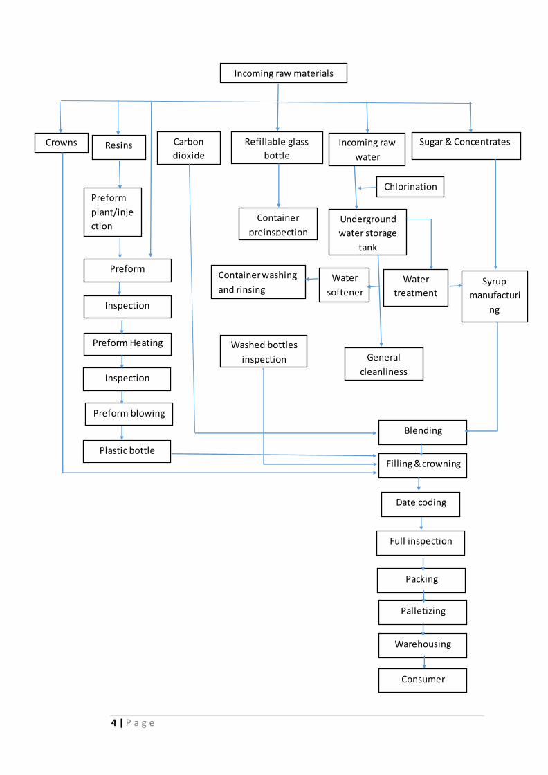
In production of plastic bottled beverage the raw materials required are resins
which are imported. They are used to produce preforms which when blown
produces plastic bottles. The following flow chart shows the flow of production
process in the industry.
4 | P a g e
Incoming raw materials
Refillable glass
bottle
Carbon
dioxide
Crowns Sugar & Concentrates
Chlorination
Container
preinspection
Underground
water storage
tank
Container washing
and rinsing Water
softener
Water
treatment Syrup
manufacturi
ng
General
cleanliness
Washed bottles
inspection
Date coding
Blending
Warehousing
Consumer
Filling & crowning
Full inspection
Packing
Palletizing
Resins
Preform
plant/inje
ction
Preform
Inspection
Preform Heating
Inspection
Preform blowing
Plastic bottle
Incoming raw
water
A
5 | P a g e
2.1 RAW MATERIALS
The raw materials that were used in the industry are Sugar and other sweeteners,
Carbon dioxide, Preservatives, color, and acidulates delivered as Part I and II,
Returnable glass bottles, resins and preforms for manufacture of plastic bottles
The industry imports sugar from abroad, normally Egypt. White sugar is mostly
used because the syrup obtained from it is clear, soft drinks like Sprite are clear
because of this property. The sugar (sucrose) is extracted from sugar cane.
2.2 UTILITIES.
2.2.1 COMPRESSED AIR
Compressed air had many uses in various areas of the industry ranging from high
pressure of 40 bar to low pressures. The compressed air came from the HP(high
pressure) compressor plant and the low pressure compressors plant. Compressed
air was used in the following production process: preform (PET) blowing in blower
moulder , cleaning in place, valves in machines and many other areas of the
industry.
HP COMPRESSORS PLANT
This plant is composed of two High pressure compressors and cooling towers
which can produces compressed air up to 40 bar mainly to be used by PET blowing
process.
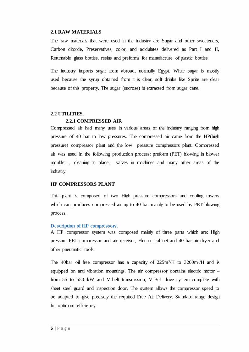
Description of HP compressors .
A HP compressor system was composed mainly of three parts which are: High
pressure PET compressor and air receiver, Electric cabinet and 40 bar air dryer and
other pneumatic tools.
The 40bar oil free compressor has a capacity of 225m3/H to 3200m3/H and is
equipped on anti vibration mountings. The air compressor contains electric motor –
from 55 to 550 kW and V-belt transmission, V-Belt drive system complete with
sheet steel guard and inspection door. The system allows the compressor speed to
be adapted to give precisely the required Free Air Delivery. Standard range design
for optimum efficiency.
6 | P a g e
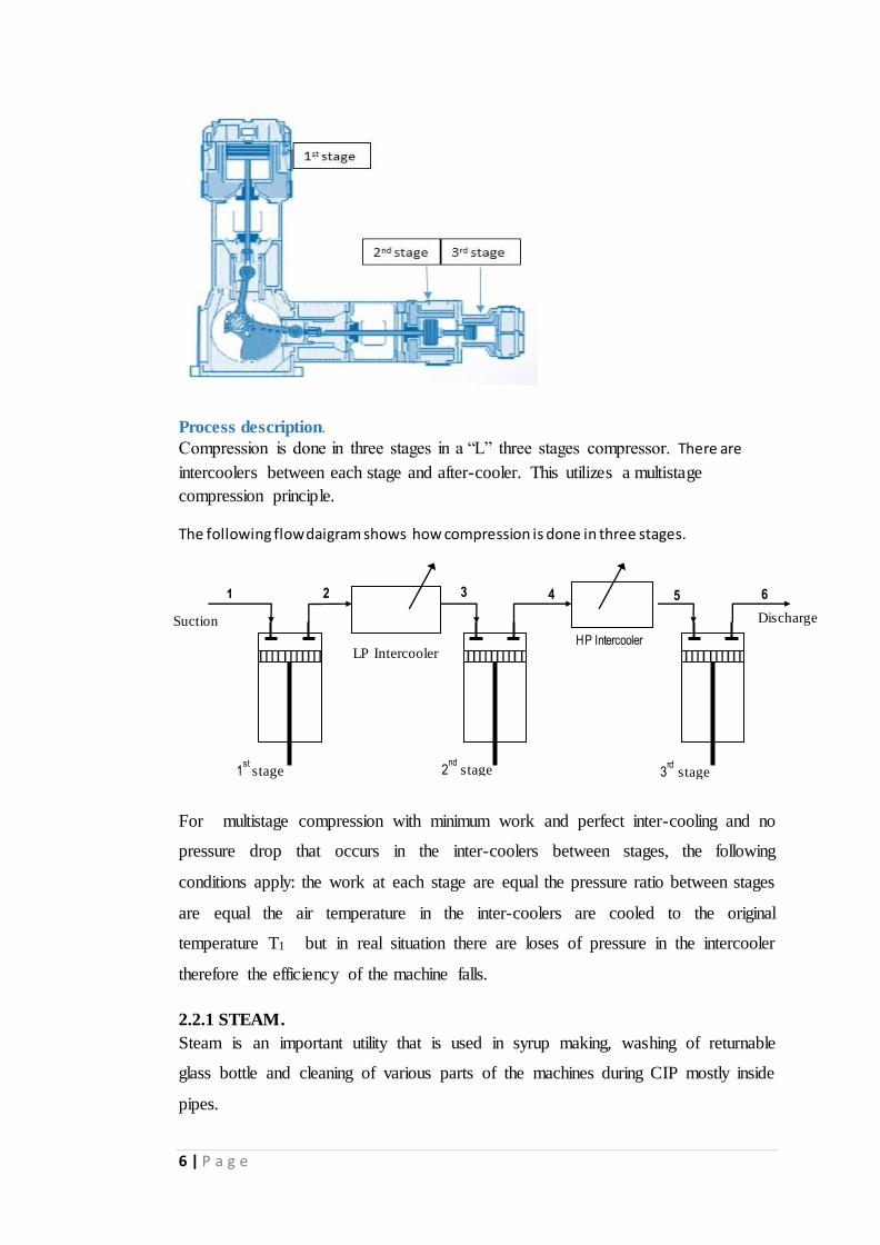
Process description. Compression is done in three stages in a “L” three stages compressor. There are
intercoolers between each stage and after-cooler. This utilizes a multistage
compression principle.
The following flow daigram shows how compression is done in three stages.
For multistage compression with minimum work and perfect inter-cooling and no
pressure drop that occurs in the inter-coolers between stages, the following
conditions apply: the work at each stage are equal the pressure ratio between stages
are equal the air temperature in the inter-coolers are cooled to the original
temperature T1 but in real situation there are loses of pressure in the intercooler
therefore the efficiency of the machine falls.
2.2.1 STEAM.
Steam is an important utility that is used in syrup making, washing of returnable
glass bottle and cleaning of various parts of the machines during CIP mostly inside
pipes.
1 2 3 4
Suction Discharge
5 6
LP Intercooler
1st
stage 2nd
stage 3rd stage
HP Intercooler
7 | P a g e
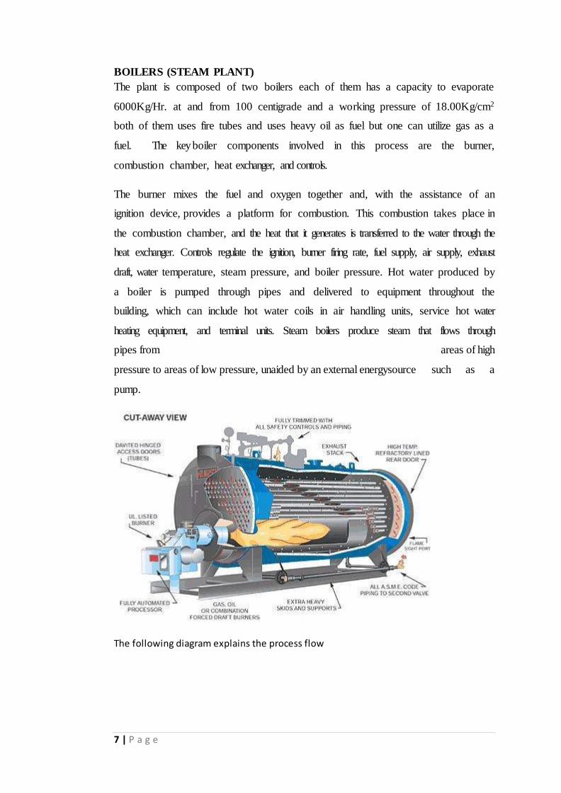
BOILERS (STEAM PLANT)
The plant is composed of two boilers each of them has a capacity to evaporate
6000Kg/Hr. at and from 100 centigrade and a working pressure of 18.00Kg/cm2
both of them uses fire tubes and uses heavy oil as fuel but one can utilize gas as a
fuel. The key boiler components involved in this process are the burner,
combustion chamber, heat exchanger, and controls.
The burner mixes the fuel and oxygen together and, with the assistance of an
ignition device, provides a platform for combustion. This combustion takes place in
the combustion chamber, and the heat that it generates is transferred to the water through the
heat exchanger. Controls regulate the ignition, burner firing rate, fuel supply, air supply, exhaust
draft, water temperature, steam pressure, and boiler pressure. Hot water produced by
a boiler is pumped through pipes and delivered to equipment throughout the
building, which can include hot water coils in air handling units, service hot water
heating equipment, and terminal units. Steam boilers produce steam that flows through
pipes from areas of high
pressure to areas of low pressure, unaided by an external energysource such as a
pump.
The following diagram explains the process flow
8 | P a g e
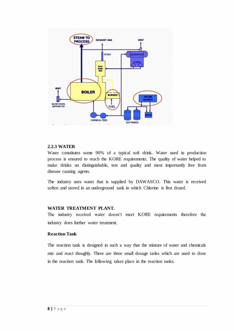
2.2.3 WATER
Water constitutes some 90% of a typical soft drink. Water used in production
process is ensured to reach the KORE requirements. The quality of water helped to
make drinks un distinguishable, test and quality and most importantly free from
disease causing agents.
The industry uses water that is supplied by DAWASCO. This water is received
soften and stored in an underground tank in which Chlorine is first dozed.
WATER TREATMENT PLANT.
The industry received water doesn’t meet KORE requirements therefore the
industry does further water treatment.
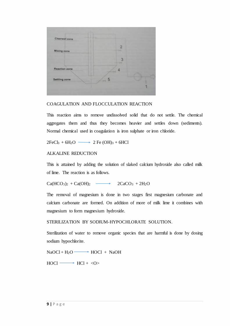
Reaction Tank
The reaction tank is designed in such a way that the mixture of water and chemicals
mix and react thoughly. There are three small dosage tanks which are used to dose
in the reaction tank. The following takes place in the reaction tanks.
9 | P a g e
COAGULATION AND FLOCCULATION REACTION
This reaction aims to remove undissolved solid that do not settle. The chemical
aggregates them and thus they becomes heavier and settles down (sediments).
Normal chemical used in coagulation is iron sulphate or iron chloride.
2FeCl3 + 6H2O 2 Fe (OH)3 + 6HCl
ALKALINE REDUCTION
This is attained by adding the solution of slaked calcium hydroxide also called milk
of lime. The reaction is as follows.
Ca(HCO3)2 + Ca(OH)2 2CaCO3 + 2H2O
The removal of magnesium is done in two stages first magnesium carbonate and
calcium carbonate are formed. On addition of more of milk lime it combines with
magnesium to form magnesium hydroxide.
STERILIZATION BY SODIUM-HYPOCHLORATE SOLUTION.
Sterilization of water to remove organic species that are harmful is done by dosing
sodium hypochlorite.
NaOCl + H2O HOCl + NaOH
HOCl HCl + <O>
10 | P a g e
DEGASEFYING TANK
This is a tank used to remove all dissolved gases and mostly it removes chloroform.
Chloroform is a bleaching agent and therefore if it is not removed it de colorize the
soft drink.
CARBON FILTERS
These filters consists of activated carbon and are responsible for removing
chemicals and impurities by the method of chemical absorption, therefore these
filters remove the rest of chlorine. In this plant there are four carbon filter tanks and
each time three are in use and one stand by.
SAND FILTERS
Sand filters are arranged to work after carbon filters and are composed of different
layers of sand varying in size which increases when to the top. The sand filters
removes pathogens, taste and odour.
REVERSE OSMOSIS PLANT (RO)
This water purification technology uses a semipermeable membrane to remove
larger particles from drinking water. Pressure is used to overcome osmotic pressure.
The plant consist of two UV treatments before and after the fibers to kill any
surviving microorganisms. There are 7 fibers and they work in set of 4-2-1.
These fibers are cleaned with citric acid.
11 | P a g e
2.3 SRYUP ROOM AND SYRUP PRODUCTION
Syrup is consists of the following compositions: water, sugar or other sweetener,
acid, sometimes fruit juice, flavors and emulsions, colors, preservatives and
antioxidants. These constituents are grouped together to form simply two parts i.e.
part I and part II. These parts are imported as raw materials.
Process description.
The production of syrup is two stages
i. Production of simple syrup
ii. Standardization to get final syrup.
In Coca Cola Kwanza the formation of beverage syrup is done in the blending
machine which is not in the syrup room.
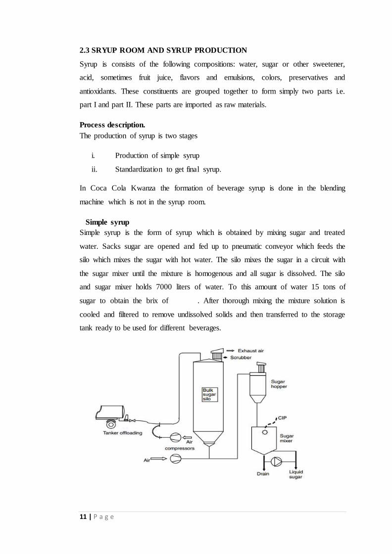
Simple syrup
Simple syrup is the form of syrup which is obtained by mixing sugar and treated
water. Sacks sugar are opened and fed up to pneumatic conveyor which feeds the
silo which mixes the sugar with hot water. The silo mixes the sugar in a circuit with
the sugar mixer until the mixture is homogenous and all sugar is dissolved. The silo
and sugar mixer holds 7000 liters of water. To this amount of water 15 tons of
sugar to obtain the brix of . After thorough mixing the mixture solution is
cooled and filtered to remove undissolved solids and then transferred to the storage
tank ready to be used for different beverages.
12 | P a g e
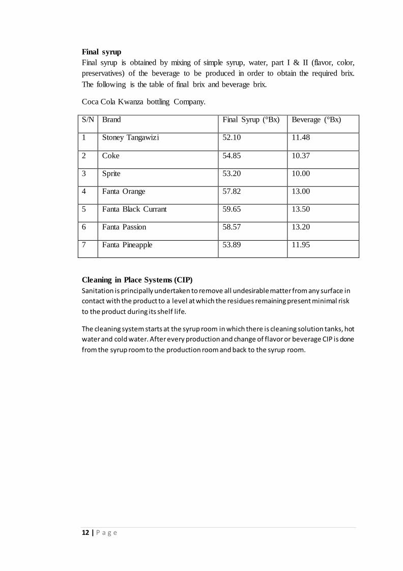
Final syrup
Final syrup is obtained by mixing of simple syrup, water, part I & II (flavor, color,
preservatives) of the beverage to be produced in order to obtain the required brix.
The following is the table of final brix and beverage brix.
Coca Cola Kwanza bottling Company.
S/N Brand Final Syrup (°Bx) Beverage (°Bx)
1 Stoney Tangawizi 52.10 11.48
2 Coke 54.85 10.37
3 Sprite 53.20 10.00
4 Fanta Orange 57.82 13.00
5 Fanta Black Currant 59.65 13.50
6 Fanta Passion 58.57 13.20
7 Fanta Pineapple 53.89 11.95
Cleaning in Place Systems (CIP)
Sanitation is principally undertaken to remove all undesirable matter from any surface in
contact with the product to a level at which the residues remaining present minimal risk
to the product during its shelf life.
The cleaning system starts at the syrup room in which there is cleaning solution tanks, hot
water and cold water. After every production and change of flavor or beverage CIP is done
from the syrup room to the production room and back to the syrup room.
13 | P a g e
2.3 BLENDING SYSTEMS (MIXER)
The blending systems for the Coca Cola Kwanza Ltd are of very little difference.
The aim was to produce drinks which are indistinguishable in taste, odour and
appearance. Therefore I am going to report both RGB and PET blenders on the
same section.
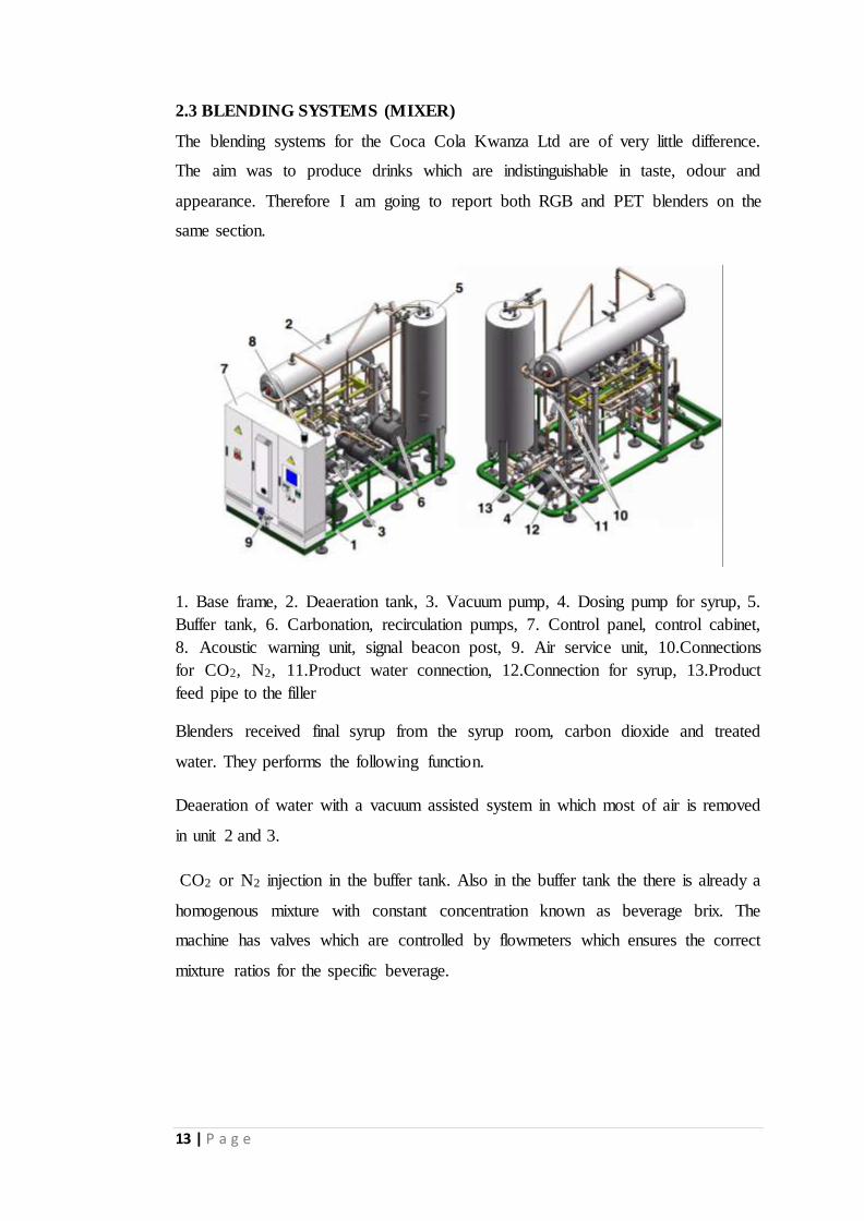
1. Base frame, 2. Deaeration tank, 3. Vacuum pump, 4. Dosing pump for syrup, 5.
Buffer tank, 6. Carbonation, recirculation pumps, 7. Control panel, control cabinet,
8. Acoustic warning unit, signal beacon post, 9. Air service unit, 10.Connections
for CO2, N2, 11.Product water connection, 12.Connection for syrup, 13.Product
feed pipe to the filler
Blenders received final syrup from the syrup room, carbon dioxide and treated
water. They performs the following function.
Deaeration of water with a vacuum assisted system in which most of air is removed
in unit 2 and 3.
CO2 or N2 injection in the buffer tank. Also in the buffer tank the there is already a
homogenous mixture with constant concentration known as beverage brix. The
machine has valves which are controlled by flowmeters which ensures the correct
mixture ratios for the specific beverage.
14 | P a g e
2.4 PLASTIC BOTTLED BEVERAGE PRODUCTION LINE
Line 5 & 6 of the manufacturing unit at Coca Cola Kwanza uses plastic bottle
containers for beverages. These plastic bottles are also used for production of
mineral water.
2.4.1 INJECTION PLANT
Injection plant produces preforms.
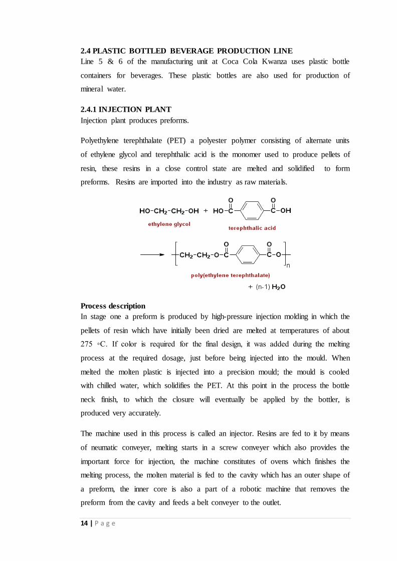
Polyethylene terephthalate (PET) a polyester polymer consisting of alternate units
of ethylene glycol and terephthalic acid is the monomer used to produce pellets of
resin, these resins in a close control state are melted and solidified to form
preforms. Resins are imported into the industry as raw materials.
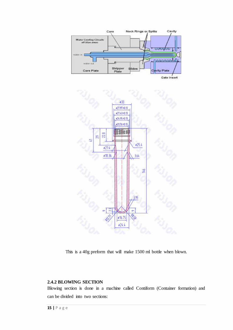
Process description
In stage one a preform is produced by high-pressure injection molding in which the
pellets of resin which have initially been dried are melted at temperatures of about
275 ◦C. If color is required for the final design, it was added during the melting
process at the required dosage, just before being injected into the mould. When
melted the molten plastic is injected into a precision mould; the mould is cooled
with chilled water, which solidifies the PET. At this point in the process the bottle
neck finish, to which the closure will eventually be applied by the bottler, is
produced very accurately.
The machine used in this process is called an injector. Resins are fed to it by means
of neumatic conveyer, melting starts in a screw conveyer which also provides the
important force for injection, the machine constitutes of ovens which finishes the
melting process, the molten material is fed to the cavity which has an outer shape of
a preform, the inner core is also a part of a robotic machine that removes the
preform from the cavity and feeds a belt conveyer to the outlet.
15 | P a g e
This is a 40g preform that will make 1500 ml bottle when blown.
2.4.2 BLOWING SECTION
Blowing section is done in a machine called Contiform (Container formation) and
can be divided into two sections:
16 | P a g e
i. Heating section
ii. Blow moulder section
At the start of the bottle blowing process, the preform is heated to get a correct
temperature profile to a maximum of about 90 ◦C. The incorrect temperature profile
could result in distortion of the neck finish which in turn will affect the distribution
of mass and handling on any air conveyor system on route to the filling and closure
application after filling. The machine constitutes of five ovens each with nine
radiation lamps. The power fed to the lamp is different and depends on the
temperature profile to be attained. There are check mats to check for defective
preforms or preforms with incorrect temperature profile.
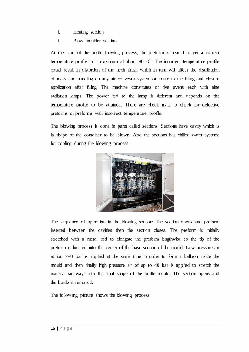
The blowing process is done in parts called sections. Sections have cavity which is
in shape of the container to be blown. Also the sections has chilled water systems
for cooling during the blowing process.
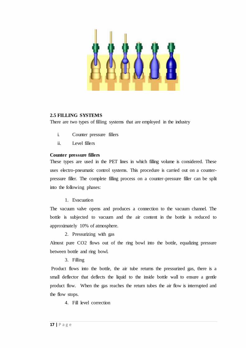
The sequence of operation in the blowing section: The section opens and preform
inserted between the cavities then the section closes. The preform is initially
stretched with a metal rod to elongate the preform lengthwise so the tip of the
preform is located into the center of the base section of the mould. Low pressure air
at ca. 7–8 bar is applied at the same time in order to form a balloon inside the
mould and then finally high pressure air of up to 40 bar is applied to stretch the
material sideways into the final shape of the bottle mould. The section opens and
the bottle is removed.
The following picture shows the blowing process
17 | P a g e
2.5 FILLING SYSTEMS
There are two types of filling systems that are employed in the industry
i. Counter pressure fillers
ii. Level fillers
Counter pressure fillers
These types are used in the PET lines in which filling volume is considered. These
uses electro-pneumatic control systems. This procedure is carried out on a counter-
pressure filler. The complete filling process on a counter-pressure filler can be split
into the following phases:
1. Evacuation
The vacuum valve opens and produces a connection to the vacuum channel. The
bottle is subjected to vacuum and the air content in the bottle is reduced to
approximately 10% of atmosphere.
2. Pressurizing with gas
Almost pure CO2 flows out of the ring bowl into the bottle, equalizing pressure
between bottle and ring bowl.
3. Filling
Product flows into the bottle, the air tube returns the pressurized gas, there is a
small deflector that deflects the liquid to the inside bottle wall to ensure a gentle
product flow. When the gas reaches the return tubes the air flow is interrupted and
the flow stops.
4. Fill level correction
18 | P a g e
The correction valve opens and pressurized carbon dioxide flows into the tube
forcing exceeded liquid to flow back to the valve.
5. Settling and snifting.
Pressure present in the bottle neck escapes until atmospheric pressure is reached
again.
Level fillers
This types of fillers utilizes mechanical filling valves with pneumatic control in line
1 and 4. It is called a mechanical valve because it controlled by external cams and
therefore the filler moves at a uniform speed so as to make the filling uniform. This
type of filler is utilized in RGB (returnable glass bottle) in which a uniform level is
important.
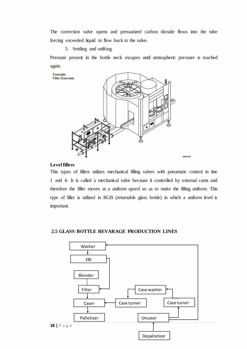
2.5 GLASS BOTTLE BEVARAGE PRODUCTION LINES
Washer
EBI
Blender
Filler
Caser
Palletizer
Uncaser
Depalletizer
Case turner
Case turner
Case washer

19 | P a g e
Glass bottles are received from the market and stored in the warehouse. The crates
are first loaded to the conveyer to the unpacker (Uncaser). The unpacked bottles are
conveyed to the washer.
2.5.1 BOTTLE WASHER
The bottle washing process is done in the following manner: pre-soak tank, the loop
guide, and the post-treatment are combined to form an individual bottle washing
system. Additional components such as high-pressure pre-jetting, heat recovery and
label removal are included in the presoak tank.
Pre-soak tank post-treatment tank
The bottle washer washes the interior and exterior of the bottle.
Interior cleaning: Rotating spraying nozzles clean the insides of the bottles from
different angles of incidence. Exterior cleaning: External cleaning is effected from
above by patented jetting units.
20 | P a g e
Interior cleaning exterior cleaning
2.5.2 EMPTY BOTTLE INSPECTION (EBI)
This is a process of visual inspection done to glass bottles to omit the defective
ones. This inspection is done using a machine called empty bottle inspection
machine. This machine constitutes cameras and light sensors that receives incident
light through the bottle. Due the shape and curvature of the bottle the received light
will have a characteristics property that describes the shape of the bottle, how the
received profile agree with prerecorded one, then the machine decides to reject or
accept the bottle. The functioning of this machine solely depend on fundamental
laws of light energy.
After the being inspected the bottle goes to the filler that uses level filling
mechanism.
2.6 DATE CODING SYSTEMS
The industry uses two types of date coding systems: Laser printing coding system,
and inkjet printing. The laser coding is used in plastic bottled beverage production
line 5 & 6 while inkjet printing is used in the glass bottle production so that it can
be removed during washing by caustic.
2.7 PACKING SYSTEMS
Glass bottle beverage packing
After being filled and caped the glass bottled beverage are packed using a machine
called caser. The machine uses a vacuum system to hold up the bottles and insert
them into crates. The crates are conveyed and placed physically onto pallets.
Plastic bottle beverage packing
The packing is done in two stages: variopac and palletizing
Variopac
The variopac wraps a plastic nylon around grouped bottles and tightened by heat
treatment. After being tightened the pack is cooled at the exit fans.
Palletizer
The industry uses a robotic machine which provides automatic means for stacking
cases of goods or products onto a pallet.

21 | P a g e
CONCLUSION
During my practical training I learnt a lot of thing concerning my course of study. I
learnt also how to work with different people in an organization by cooperation.
Apart from that I enjoyed a lot both practical works assigned to me because they
made me become confident and familiar mostly to processes in the industry.
RECOMENDATION
The industry should support creativity of the workers by implementing the work
rotation. Rotation of jobs will add skills and knowledge to the workers and also
motivates them to work hard.

22 | P a g e
23 | P a g e
PROJECT: BOILERS EFFICIENCY
Introduction
The industry has two boilers Forbes Marshall boiler and Thompson Africa Redipac
boiler.
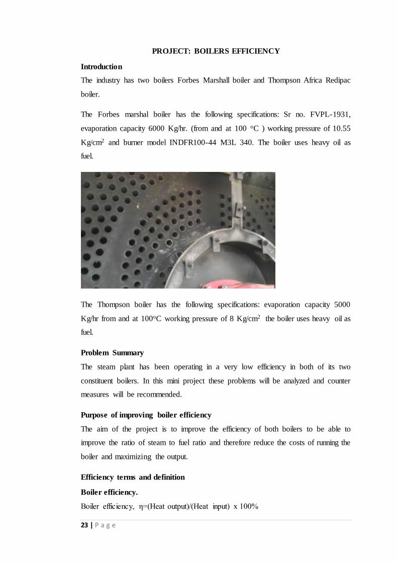
The Forbes marshal boiler has the following specifications: Sr no. FVPL-1931,
evaporation capacity 6000 Kg/hr. (from and at 100 oC ) working pressure of 10.55
Kg/cm2 and burner model INDFR100-44 M3L 340. The boiler uses heavy oil as
fuel.
The Thompson boiler has the following specifications: evaporation capacity 5000
Kg/hr from and at 100oC working pressure of 8 Kg/cm2 the boiler uses heavy oil as
fuel.
Problem Summary
The steam plant has been operating in a very low efficiency in both of its two
constituent boilers. In this mini project these problems will be analyzed and counter
measures will be recommended.
Purpose of improving boiler efficiency
The aim of the project is to improve the efficiency of both boilers to be able to
improve the ratio of steam to fuel ratio and therefore reduce the costs of running the
boiler and maximizing the output.
Efficiency terms and definition
Boiler efficiency.
Boiler efficiency, η=(Heat output)/(Heat input) x 100%
24 | P a g e
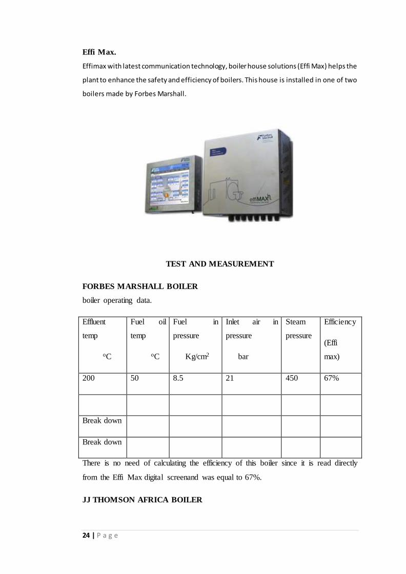
Effi Max.
Effimax with latest communication technology, boiler house solutions (Effi Max) helps the
plant to enhance the safety and efficiency of boilers. This house is installed in one of two
boilers made by Forbes Marshall.
TEST AND MEASUREMENT
FORBES MARSHALL BOILER
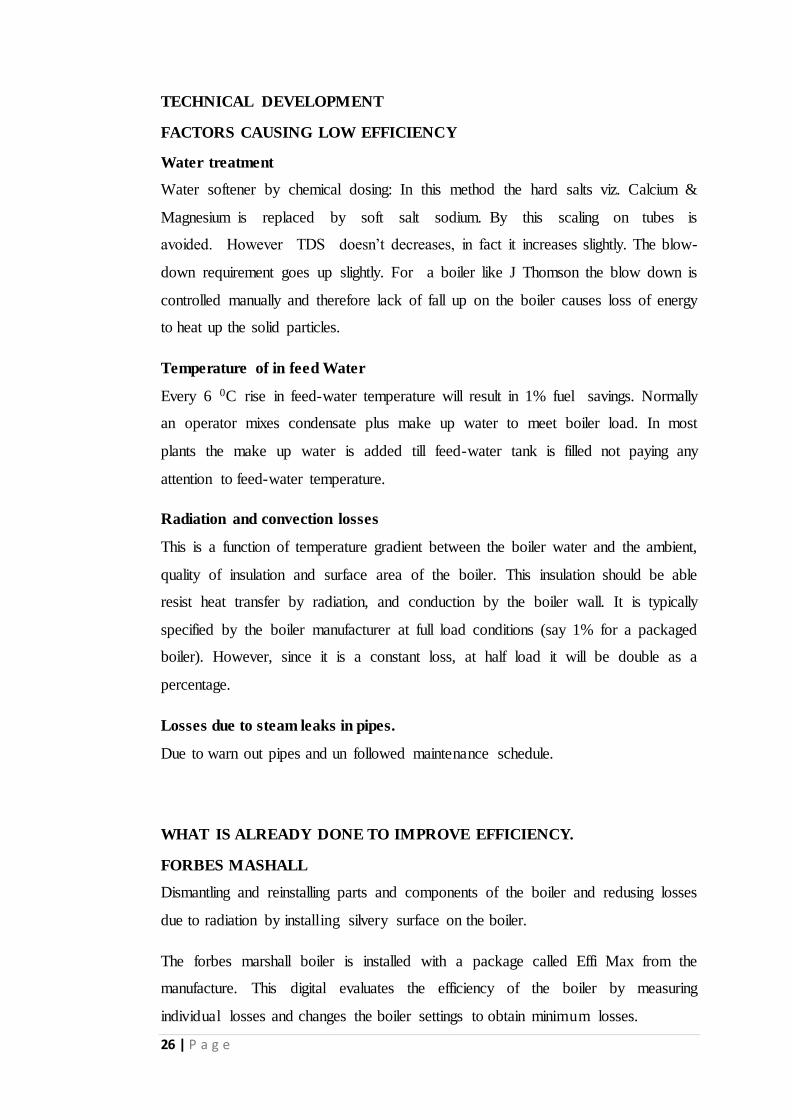
boiler operating data.
Effluent
temp
oC
Fuel oil
temp
oC
Fuel in
pressure
Kg/cm2
Inlet air in
pressure
bar
Steam
pressure
Efficiency
(Effi
max)
200 50 8.5 21 450 67%
Break down
Break down
There is no need of calculating the efficiency of this boiler since it is read directly
from the Effi Max digital screenand was equal to 67%.
JJ THOMSON AFRICA BOILER

25 | P a g e
Effluent
temp
oC
Fuel oil
temp
oC
Fuel in
pressure
Kg/cm2
Inlet air in
pressure
bar
Steam
pressure
KPa
190 50 8.5 21 450
190 53 8.5 25 450
200 55 8.4 21 450
190 50 8.5 21 450
Boiler Efficiency by Direct Method in the J Thompson Africa boiler
Heat output data
Quantity of steam generated (output) quantity (Q) : 4 TPH
pressure / temperature :8 kg/cm2
Enthalpy of steam (g)/ 180 0C (dry & Saturated) : 2815.57 KJ/kg
at 8 kg/cm2(g) pressure (H)
Feed water temperature : 330C
Enthalpy of feed water at 1atm (h) : 138.37 KJ/Kg
Heat input data
Quantity of coal consumed (Input) : 0.309 TPH
GCV of HFO (heavy fuel oil) : 44782.6 KJ/Kg
Efficiency Calculation
Boiler efficiency(η)= (Q*(H-h)) /(q*GCV)
η= 77%
The efficiency of J Thompson boiler is 77%
26 | P a g e
TECHNICAL DEVELOPMENT
FACTORS CAUSING LOW EFFICIENCY
Water treatment
Water softener by chemical dosing: In this method the hard salts viz. Calcium &
Magnesium is replaced by soft salt sodium. By this scaling on tubes is
avoided. However TDS doesn’t decreases, in fact it increases slightly. The blow-
down requirement goes up slightly. For a boiler like J Thomson the blow down is
controlled manually and therefore lack of fall up on the boiler causes loss of energy
to heat up the solid particles.
Temperature of in feed Water
Every 6 0C rise in feed-water temperature will result in 1% fuel savings. Normally
an operator mixes condensate plus make up water to meet boiler load. In most
plants the make up water is added till feed-water tank is filled not paying any
attention to feed-water temperature.
Radiation and convection losses
This is a function of temperature gradient between the boiler water and the ambient,
quality of insulation and surface area of the boiler. This insulation should be able
resist heat transfer by radiation, and conduction by the boiler wall. It is typically
specified by the boiler manufacturer at full load conditions (say 1% for a packaged
boiler). However, since it is a constant loss, at half load it will be double as a
percentage.
Losses due to steam leaks in pipes.
Due to warn out pipes and un followed maintenance schedule.
WHAT IS ALREADY DONE TO IMPROVE EFFICIENCY.
FORBES MASHALL
Dismantling and reinstalling parts and components of the boiler and redusing losses
due to radiation by installing silvery surface on the boiler.
The forbes marshall boiler is installed with a package called Effi Max from the
manufacture. This digital evaluates the efficiency of the boiler by measuring
individual losses and changes the boiler settings to obtain minimum losses.
27 | P a g e
The EffiMax package includes:
i. Oxygen analyzer for excess air measurement in flue gas.
ii. Stack temperature measurement
iii. Feed-water temperature measurement for enthalpy calculation
iv. High accuracy ,Low pressure drop vortex type steam flow meter
v. Steam temperature measurement for enthalpy calculation
vi. Automatic Blow-down control System .
vii. Computation & display unit
viii. Data acquisition & diagnostic software package.
The EffiMax Package provides online recording and trend analysis for the
following parameters: Boiler efficiency %, Stack loss %, Enthalpy loss %,
Combustion loss %, Radiation loss %, Total blow-down loss , % blow-down loss
& Average blow-down loss, Steam to fuel ratio
J THOMSON AFRICA BOILER
Repair of leaking steam pipes on this boiler was done.
EFFICIENCY IMPROVEMENT
FORBES MARSHALL BOILER & J THOMPSON AFRICA
Since Forbes Marshall boiler has Effi Max package for maximizing efficiency
already installed the following can be done that is not covered by Effi Max.
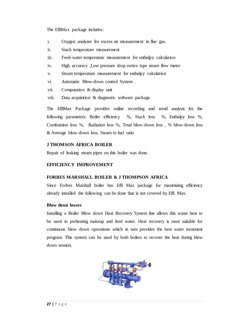
Blow down losses
Installing a Boiler Blow down Heat Recovery System line allows this waste heat to
be used in preheating makeup and feed water. Heat recovery is most suitable for
continuous blow down operations which in turn provides the best water treatment
program. This system can be used by both boilers to recover the heat during blow
down session.
28 | P a g e
This will increase boiler efficiency up to 2%
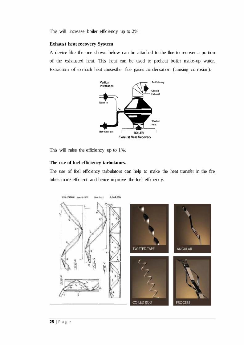
Exhaust heat recovery System
A device like the one shown below can be attached to the flue to recover a portion
of the exhausted heat. This heat can be used to preheat boiler make-up water.
Extraction of so much heat causesthe flue gases condensation (causing corrosion).
This will raise the efficiency up to 1%.
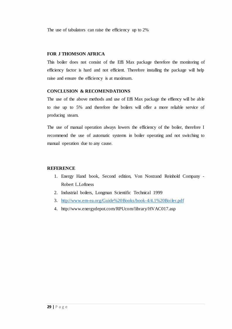
The use of fuel efficiency tarbulators.
The use of fuel efficiency tarbulators can help to make the heat transfer in the fire
tubes more efficient and hence improve the fuel efficiency.
29 | P a g e
The use of tabulators can raise the efficiency up to 2%
FOR J THOMSON AFRICA
This boiler does not consist of the Effi Max package therefore the monitoring of
efficiency factor is hard and not efficient. Therefore installing the package will help
raise and ensure the efficiency is at maximum.
CONCLUSION & RECOMENDATIONS
The use of the above methods and use of Effi Max package the effiency will be able
to rise up to 5% and therefore the boilers will offer a more reliable service of
producing steam.
The use of manual operation always lowers the efficiency of the boiler, therefore I
recommend the use of automatic systems in boiler operating and not switching to
manual operation due to any cause.
REFERENCE
1. Energy Hand book, Second edition, Von Nostrand Reinhold Company -
Robert L.Loftness
2. Industrial boilers, Longman Scientific Technical 1999
3. http://www.em-ea.org/Guide%20Books/book-4/4.1%20Boiler.pdf
4. http://www.energydepot.com/RPUcom/library/HVAC017.asp