best practice guide - university of waterloo€¦ · · 2001-09-21best practice guide building...
TRANSCRIPT

Building Technology–Flashings
CMHC offers a wide range of housing-related information. For details, contact your local CMHC office or call 1 800 668-2642.
Cette publication est aussi disponible en français sous le titre : Solins–LNH 6920.
FLASHINGS
BEST PRACTICE GUIDE
BUILDING TECHNOLOGY

Canadian Cataloguing in Publication Data
Malhotra, Ashok, 1950-
Flashings
(Best practice guide: building technology)Issued also in French under title: Solins.Accompanied by CD-ROM with CAD drawings.Includes bibliographical references.ISBN 0-660-17111-2Cat. no. NH15-132/2-1997E
1. Roof drainage.2. Roofs–Design and construction.I. Canada Mortgage and Housing Corporation.II. Title.III. Series.
TH2481.M34 1997 690’.15 C97-980308-X
© 1998, Canada Mortgage and Housing Corporation. All rights reserved. No portion of thisbook may be reproduced, stored in a retrieval system or transmitted in any form or by anymeans, mechanical, electronic, photocopying, recording or otherwise without the prior writtenpermission of Canada Mortgage and Housing Corporation. Without limiting the generality ofthe foregoing no portion of this book may be translated from English into any other languagewithout the prior written permission of Canada Mortgage and Housing Corporation.
Printed in CanadaProduced by CMHC
Building Technology–Flashings

Building Technology–Flashings
CMHC STATEMENT
Canada Mortgage and HousingCorporation, the Federal Government’s housing agency, is responsible foradministering the National Housing Act.
This legislation is designed to aid in the improvement of housing and livingconditions in Canada. As a result, the corporation has interests in all aspectsof housing and urban growth and development.
Under Part IX of this Act, the Government of Canada provides funds toCMHC to conduct research into the social, economic, and technical aspectsof housing and related fields, and to publish and distribute the results of thisresearch. CMHC therefore has a statutory responsibility to make widelyavailable information that may be useful in the improvement of housing andliving conditions.
This publication is one of the many items of information published byCMHC with the assistance of federal funds.
ACKNOWLEDGEMENTS
This guide was prepared for the High RiseInnovation Centre, Canada Mortgage and Housing Corporation by AshokMalhotra, P.Eng., Halsall Associates Limited in joint venture with HerbOtto, B.Arch, OAA, MRAIC, Otto, Bryden, Erskine, Martel ArchitectsInc., Otto & Erskine Architects Inc. The development of this guide hasbeen greatly assisted by the expertise of Masonry Canada.
DisclaimER
The analysis, interpretations, andrecommendations are those of the consultants and do not necessarily reflectthe views of CMHC or those divisions of the corporation that assisted inpreparation and publication.
Care has been taken to review the research summarized in this guide, but noattempt has been made to replicate or check experimental results or validatecomputer programs. Neither the authors nor CMHC warrant or assume anyliability for the accuracy or completeness of the text, drawings, oraccompanying CD-ROM, or their fitness for any particular purpose orproject. It is the responsibility of the user to apply professional knowledge inthe use of the information contained in these drawings, specifications, andtexts, to consult original sources, or when appropriate, to consult an architector engineer.


Building Technology–Flashings
i
1 / BASICS OF FLASHINGS
Definition 1-1
Control of Forces Directing Water Flow 1-1
Flashing Performance Requirements 1-2
Flashing Locations 1-4
Types of Flashings 1-4
Flashing Materials and Installation 1-10
2 / DETAILS
Introduction 2-1
3 / INSPECTION AND QUALITY CONTROL
Quality 3-1
Responsibilities 3-1
Quality Control and Quality Assurance 3-2
Steps for Quality Assurance of Flashings 3-2
Flashings: Site Inspection Checklist 3-3
4 / SAMPLE SPECIFICATIONS
Preamble 4-1
Section 04150 Masonry Procedures 4-2
Section 07620 Metal Flashings 4-4
Section 07900 Sealants 4-8
5 / CAD DETAIL LIBRARY
Overview 5-1
Assumption 5-1
Disclaimer 5-1
What’s on the Disk 5-1
References
References R-1
appendix a
Files on CD-ROM A-1
table of contents

table of contents Building Technology–BVCM
ii
List of tables
Table 1.1: Galvanic Scale 1-3
Table 1.2: Joint Width and Depth 1-15
Table 1.3: Flashing Materials 1-17
Table 3.1: Site Inspection Checklist 3-3
list of figures
Figure 1.1: Base flashing 1-5
Figure 1.2: Base flashing 1-5
Figure 1.3: Counter flashing 1-6
Figure 1.4: Valley flashing 1-6
Figure 1.5: Stepped flashing 1-7
Figure 1.6: Wall flashing 1-7
Figure 1.7: Wall flashing 1-8
Figure 1.8: Cap flashing 1-8
Figure 1.9: Damp-proof flashing 1-9
Figure 1.10: Drip flashing 1-9
Figure 1.11: Flashings with end dams 1-13
Figure 1.12: Sealant joint 1-13
Figure 1.13: Proper joint design 1-15
List of details
Detail 2.1: Foundation Wall/Brick Veneer Intersection Wood-Frame Wall–Flashing 2-3
Detail 2.2: Stepped Foundation Wall–Masonry Veneer 2-5
Detail 2.3a: Precast Window Sill–Wood-Frame Wall 2-7
Detail 2.3b: Flashing/Sill Types 2-9
Detail 2.4: Metal Window Sill/Extruded Aluminum Sill with Rain Deflector 2-11
Detail 2.5: Jointed Precast Window Sill–Brick Veneer 2-13
Detail 2.6: Window/Door Head Brick Veneer 2-17
Detail 2.7: Shelf Angle at Concrete Slab–Brick Veneer/CMU 2-19
Detail 2.8: Wall Penetration–Masonry Veneer/CMU 2-23
Detail 2.9: Low Parapet–Brick Veneer 2-25
Detail 2.10: Door Sill–Balcony Location–Flashing 2-27
Detail 2.11: Sloped Roof/Wall Intersection–Wood-frame 2-29
Detail 2.12: Sloped Roof/Wall Intersection–Brick Veneer 2-31
Detail 2.13a: Roof Penetrations–Brick Chimney 2-33
Detail 2.13b: Roof Penetrations–Upper Side of Brick Chimney 2-35
Detail2.13c: Roof Penetrations–Brick Chimney Saddle 2-37
Detail 2.14: Damp-proof Flashing–Exposed Masonry Wall 2-39
Detail 2.15: Foundation Wall–Stucco Veneer 2-41
Detail 2.16: Window/Door Head–Stucco Veneer 2-43
Detail 2.17: Foundation Wall–Vinyl, Aluminum Siding 2-45

Building Technology–Flashings
iii
Detail 2.18: Foundation Wall–At Precast Steps 2-47
Detail 2.19: Window Sill–Wood, Vinyl, Aluminum Siding 2-49
Detail 2.20: Window/Door Head–Wood, Vinyl, Aluminum Siding 2-51
Detail 2.21: Overhang–Wood, Vinyl, Aluminum Siding 2-53
Detail 2.22a: Flat Roof/Wall Above (Terrace)–Wood, Vinyl, Aluminum Siding 2-55
Detail 2.22b: Flat Roof/Door Sill (Terrace)–Wood, Vinyl, Aluminum Siding 2-57
Detail 2.23: Medium/High Parapet–Prefinished Veneer 2-59
Detail 2.24: Flat Roof Edge Flashing 2-61
Detail 2.25: Sloped Shingle Roof Eave 2-63
Detail 2.26a: Ridge Vent–Sloped Shingle Roof 2-65
Detail 2.26b: Roof to Wall Vent–Sloped Shingle roof 2-67
Detail 2.27a: Skylight–Horizontal Section A 2-69
Detail 2.27b: Skylight–Vertical Section B1 2-70
Detail 2.27c: Skylight–Vertical Section B2 with Saddle 2-71
Detail 2.27d: Skylight–Showing Rubberized Asphalt Sheet Underlay 2-72
Detail 2.27e: Skylight–Isometric Showing Base Flashing Over Underlay 2-73
Detail 2.27f: Skylight–Isometric Showing Saddle and Step Flashing 2-75
Detail 2.28: Open Valley–Asphalt Shingle Roof 2-77
Detail 2.29: Closed and Woven Valley Flashing 2-79
Detail 2.30: Roof Area Divider 2-81
Detail 2.31:Building Movement Joint at Roof 2-83
Detail 2.32: Firewall for Sloped Shingle Roof 2-85
Detail 2.33: Parapet Flashing–Connection Details 2-87
Detail 2.34: Roof Penetrations–Vent Pipe–Built-up Roof 2-89
Detail 2.35: Roof Penetrations–Prefabricated Vent/Pipe Flashing–Shingle Roof 2-91
Detail 2.36: Roof Penetrations–Prefabricated Stack Flashing–Built-up Roof 2-93
Detail 2.37: Roof Penetrations–Insulated Curbed Opening–Built-up Roof 2-95
Detail 2.38: Roof Penetrations–Insulated Pipe Enclosure–Built-up Roof 2-97
Detail 2.39: Roof Penetrations–Vent Curb–Built-up Roof 2-99
table of contents

Building Technology–Flashings
iv
PREFACE
This document provides designers,builders, building owners and building managers with a generalunderstanding of the principles and best practices in the design andconstruction of flashings.
Studies of roofing failures and cladding problems have shown that a highpercentage of these problems are the result of inadequate design andconstruction of flashings.
Details illustrated in this document represent commonly used flashingconstruction. These details are intended to illustrate the flashings componentonly. Other building components are shown in the detail only to complete theillustration; information about them may be incomplete. Other Best PracticeGuides deal with full details for different wall systems.
The information in this document is based on building codes, the CanadianRoofing Contractor’s Association Manual, publications of the NationalResearch Council and Canada Mortgage and Housing Corporation, and theauthors’ direct experience. A draft of this document was widely circulated,and, wherever possible and appropriate, the authors incorporated thesuggestions of the reviewers.
CAUTION
Before the details in this document areincorporated into buildings, they must be reviewed by professionalsexperienced in this field. This document is only a guide to current bestpractice in the design and construction of flashings. It cannot replaceprofessional advice.

Building Technology–Flashings
1-1
Definition
Flashings are an important line of defence ina building’s moisture protection assemblies. Flashings are components of theexterior envelope used to intercept and direct the flow of water to designeddrainage paths. They prevent water from penetrating the building. Flashingsare also used to direct water away from building elements susceptible todeterioration–by staining, erosion, frost damage and corrosion–when exposedto excessive wetting.
Control of the ForcesDirecting Water Flow
When designing or constructing flashings,the forces that drive the flow of water need to be considered, since water canmove upward and sideways as well as downward.
GravityWater flows downward, from the pull of gravity. Detailing must consider thefollowing:• Surfaces should slope in the desired direction of flow (minimum 10%
slope).• A build-up of water on the flashing surface should be anticipated,
particularly if there is a risk of heavy flow or if normal drainage paths areblocked by ice or other obstructions. Directions of flow might then differfrom that expected for the slope.
• Points of discharge should project out beyond materials below the flashingthat may deteriorate when in contact with water or ice.
• Terminations on sloped surfaces should be lapped in shingle fashion sothat the natural direction of the water is over and onto the next water-shedding surface.
Surface Tension and Capillary ActionSurface tension allows water to flow along the underside of a surfacehorizontally, and even upward, in narrow spaces such as crevices. In confinedspaces, spacing horizontal surfaces more than 9 mm (0.38 in.) apart willprevent the adherence of water to the two surfaces, thus allowing the water todrain away. A “drip” edge is placed at points of discharge to break thatsurface tension and allow water to drop by gravity.
Water can be drawn into small-diameter (less than 5 mm [0.20 in.]) openingsby capillary action, or “wicking,” in porous materials such as concrete andbrick. The flashing joints should inhibit this action. Design of joints andupturns needs to take this characteristic into consideration.
Kinetic EnergyRain is often directed at flashings with a high velocity and significanthorizontal motion. On the upper locations of buildings, the wind actuallycarries rain drops upward. The momentum of wind forces can be strongenough to carry the rain drops through even small unsealed joints oropenings.
Chapter 1
BASICS OFflashings

BASICS OF FLASHINGS Building Technology–Flashings
1-2
Differential Pressures and Air CurrentsDifferential pressures and air flow often occur in ways that drive waterthrough unsealed or poorly sealed joints. Air pressure can drive waterthrough even small holes and gaps. To prevent this, care must be taken whenincorporating a flashing into the building air barrier. Alternatively, the jointmay be sealed. Flashings at the top of buildings, such as at parapets, aresubject to uplift. They should be anchored to the wall securely, and sealed toprevent water ingress. Other systems, such as pressure equalized rainscreens,act as another line of defense in a building’s moisture protection. Moreinformation on this subject can be found in other Best Practice Guides.
Flashing PerformanceRequirements
In selecting materials to be used as flashing,the following performance requirements should be considered:
Water BarrierThe flashing assembly including materials and joints must shed waterwithout allowing leakage.
The ability of the flashing to seal and be detailed to avoid leakage isfundamental. Creating an effective and durable joint seal is often difficult. Itis good practice to provide a secondary, continuous flexible membraneflashing under jointed materials, such as brick, stone or sheet metal.
Movement CapabilityThe flashing must be able to accommodate differential thermal and structuralmovements. It must either be made of a flexible material or have jointsdesigned to accommodate movement. Movements to be considered include:thermal expansion and contraction of all building components, including theflashing itself; normal deflections under service loads; shrinkage and creep ofconcrete and wood; and expansion of brick after construction.
TerminationsTerminations should be able to be formed into sharp breaks and to besufficiently rigid at points of discharge to adequately project water away frommaterials below.
DurabilityThe flashing must be tough enough to resist physical damage duringconstruction, as well as during normal wear, which may be related to theenvironment and building-maintenance activities. Other factors to beconsidered include deterioration from corrosion, metal incompatibility andgalvanic action, deterioration due to exposure to ultraviolet (UV) light,extreme (hot and cold) temperatures, freezing water, and fatigue due tomovements.
For more information on durability, the CSA Standard S478, “DurabilityGuidelines,” should be consulted. In general, the service life of flashingsmust be equal to or more than that of the wall system or roof system atlocations where maintenance or replacement of flashings would beuneconomical.

Building Technology–Flashings
1-3
Refer to Table 1.3 (page 1-17X) for flashing materials affected by ultraviolet(UV) radiation. These materials must be protected from sunlight by counterflashings.
CompatibilityFlashings, and their primers and sealants, must all be chemically compatiblewith adjacent materials. Avoid contact between dissimilar metals, as this canlead to galvanic corrosion when the metals are moist. The water acts as theelectrolyte, and the dissimilar metals act as electrodes.
The galvanic scale classifies metals by how chemically active they are. Whentwo dissimilar metals come in contact under moist conditions, the moreactive metal corrodes because of the transfer of ions to the more passivemetal; the more passive metal remains unharmed. The farther apart the metalsare on the list, the faster the ion exchange and the greater the corrosion. Ifdissimilar metals must be adjacent, separate them with building paper or abituminous membrane.
Alkaline concrete and mortar aggressively attack materials such as aluminumand copper. Consult the manufacturers of selected materials to determinewhether adjacent materials will be compatible.
BuildabilityCreating a flashing detail that is easy to build will greatly increase thelikelihood that the flashing will be built to perform acceptably.Considerations include:• Can the installation of flashings be sequenced so that it is separate from
other construction activities, or can it be easily incorporated into otherwork? For example, coordination may be required between roofing andmasonry activities at wall-roof junctions.
• If the installation of the flashings is to be incorporated into other work, dothe workers have the required technology and skills?
• Can the flashing accommodate normal stresses?• Is it possible to mould or modify the material to accommodate unusual
conditions, or is it possible to repair damage?
MaintenanceBesides durability, future maintenance of the flashing must be considered.Materials or joint sealants with limited service lives should be avoided if theflashings are not accessible for replacement.
BASICS OF FLASHINGS
Table 1.1: Galvanic Scale
ACTIVE PASSIVE
Zinc Copper
Aluminum
Steel
Cast Iron
Lead
Tin

BASICS OF FLASHINGS Building Technology–Flashings
1-4
Metal flashings anchored by being built into concrete or masonry cannot beremoved to allow for inspection or repair of the materials underneath. Thisshould be considered when selecting materials and details for flashings.
The flashings and sealants should be inspected annually, particularly in areaswith the greatest exposure to water and sunlight. The following are signs ofdeterioration to investigate and rectify:• corrosion• missing anchorage• displacement or damage• unusual movement• signs of water leakage• efflorescence• deteriorated sealants
Flashing Locations
Typical flashing locations include:
• top of exposed walls• at roof-wall junctions• around penetrations through roofing • at valleys in steep roofs• within walls above doors, windows and other wall penetrations• at foundation level, to lead water out of the cavity• at locations where water might enter the building through a juncture
between two materials
Types of Flashings
The names used to define flashings give anindication of their function and location. The most common types aredescribed below.
Base FlashingAt the intersection of a roof with a wall or another roof penetration, such as aplumbing vent, the roofing system should be turned up to make the junctionwatertight. The part of the roofing that is turned up is generally known as a“base flashing.” It may be made of the same material as the main roofingmembrane or of a compatible material (see Figures 1.1 and 1.2).

Building Technology–Flashings
1-5
BASICS OF FLASHINGS
Figure 1.1: Base flashing
Figure 1.2: Base flashing

BASICS OF FLASHINGS Building Technology–Flashings
1-6
Counter Flashing To prevent water from penetrating behind the top edge of base flashing, aseparate piece of flashing should be provided over the top. This flashingis known as a “counter flashing” and is usually made of sheet metal(see Figure 1.3).
Counter flashing is also required to protect the base flashing from impactdamage and damage from UV radiation. This is necessary if the base flashingis a built-up bituminous roofing membrane or made of any material thatdeteriorates in sunlight.
Where siding is used as cladding material, the base flashing is turned upbehind the siding. Counter flashings should be installed so that they areeasily removed to allow for inspection of the flexible base flashing below.
Valley FlashingA “valley flashing” should be installed in the valleys of sloping shingle roofsto give continuity to the roofing system (see Figure 1.4).
Figure 1.3: Counter flashing
Figure 1.4: Valley flashing

Building Technology–Flashings
1-7
Stepped Flashing or Shingled, Stepped Base Flashingfor Shingled RoofsAt the junction between a roof sloping parallel to a wall, stepped baseflashing should be installed in pieces, making it follow the slope. The piecesof flashing are overlapped like the roof shingles. Both base flashing andcounter flashing are installed in pieces (see Figure 1.5).
Wall Flashing
Wall flashings (see Figures 1.6 and 1.7) prevent water from penetrating thecavity by wind-driven rain, and by air leakage and vapour diffusion from theinterior, which result in condensation. A wall flashing intercepts and directsany water flowing down the cavity to the exterior.
BASICS OF FLASHINGS
Figure 1.5: Stepped flashing
Figure 1.6: Wall flashing

BASICS OF FLASHINGS Building Technology–Flashings
1-8
Cap FlashingExterior walls require a “cap” to prevent water from penetrating from the topof the wall. A metal cap flashing does this (see Figure 1.8). The cap flashingsheds water and must be sloped toward the roof to prevent staining of theexterior cladding. It cannot be made waterproof at the joints, and it requires asecondary, continuous and waterproof flashing below it.
Figure 1.7: Wall flashing
Figure 1.8: Cap flashing

Building Technology–Flashings
1-9
Damp-proof Through-wall FlashingPrecast concrete, stone masonry or brick units known as copings close thetops of masonry walls or act as window and door sills. These units also serveto prevent water from entering the top of the wall. If the copings are installedin sections, water may leak through the joints. A damp-proof flashing shouldbe placed between the coping and the top of the masonry wall to preventwater from penetrating into the wall below (see Figure 1.9). Using a damp-proof flashing is also good building practice if copings or sills without jointsare used.
Drip FlashingA drip flashing (see Figure 1.10) should be provided at the base of claddingsystems. Drip flashings intercept moisture that has entered behind thecladding and direct it to the outside, as well as redirect water flowing downthe face of the wall to prevent it from dripping down on the materials below.
BASICS OF FLASHINGS
Figure 1.9: Damp-proof flashing
Figure 1.10: Drip flashing
BASICS OF FLASHINGS Building Technology–Flashings
1-10
Flashing Materials andInstallation
Generally, a variety of factors determinesthe selection of the flashing material, including function, availability,aesthetics and cost. The cost of the material needs to be carefully weighedagainst these other factors. One should consider not only the initial materialcost but also the performance over the life of the building. Durability andease of maintenance and repair should also be considered. For example,stainless steel through-wall flashings are commonly used in heritagebuildings because these flashings are more durable.
The following sections describe some of the materials available, theirlimitations and typical installation practices.
Base FlashingsThe following are typical base flashing materials and methods of installation:
General Considerations
• Base flashings used in flat roofs are generally membranes made of thesame type of material as, or compatible with, those of the roofing system.
• Base flashings used for shingled roofs are generally metal.• Metal base flashings are not used with bituminous or elastomeric
membranes. Metal flashings are not flexible enough to mould to thesupports, and metals have expansion coefficients incompatible with suchroofing materials, which makes maintaining the bond between the twomaterials almost impossible.
• Base flashings must extend up the parapet and over the top (see Figure 1.8,page 1-8).
Built-up Bituminous Roofing
• Base flashings should be made of a built-up bituminous membrane similarto that of the main roofing system and constructed with the same numberof plies. Use Type III asphalt for vertical upturns, with paper or organicfelts. This type of asphalt is less susceptible to sagging, and the felts holdthe asphalt better on a vertical surface than do the fibreglass feltscommonly used for a roof.
• Treated wood or fibre cant should be provided to facilitate turning up theroofing felts to the vertical.
• Flashing felts should be lapped at a minimum of 150 mm (6 in.) over theroofing felts, at the cants. Termination of the flashing felts should bestaggered on the horizontal surface.
• Membrane flashing is nailed at a minimum of 200 mm (8 in.) above thefinished roof membrane. Where necessary, nailing blocks or strips shouldbe provided. Corrosion-resistant fasteners should be used with a maximumspacing of 300 mm (12 in.).
• Metal counter flashing should be provided to protect the base flashingfrom UV radiation.

Building Technology–Flashings
1-11
Modified Bituminous Roll RoofingThese membrane systems typically consist of two plies: a base sheet and acap sheet. The application procedures may vary between manufacturers butthe procedures described below are fairly typical.• The roofing membrane and flashings may be different types of modified
bituminous roll roofing (MBR) membranes. The membrane may be heat-welded to the vertical support, adhered with an adhesive, or self-adhered.
• MBR flashings are typically lapped over and adhered to the roofingmembrane at a minimum of 150 mm (6 in.) along the horizontal surface.They extend up the wall to a minimum of 200 mm (8 in.) above thefinished roof surface.
• The top edge of the flashing membrane should be mechanically fastenedusing a corrosion-resistant bar and fasteners, at a maximum of 300 mm(12 in.).
• Where the cap sheet will be left exposed, it must have embedded mineralgranules to protect it from the effects of UV radiation. In this case, theremay be no need to have metal counter flashing extending down to protectthe membrane.
Elastomeric Roofing Materials
• Elastomeric roofing materials (e.g., PVC, EPDM) should be extended upthe wall as base flashings.
• The membrane should be fully adhered to the vertical surface andmechanically fastened at the top edge, as indicated for the MBRmembrane. Precautions must be taken to secure the roofing membrane atthe perimeter.
• Unless the membrane is resistant to UV radiation, the counter flashingmust be extended to protect it. In any case, it is appropriate to extendcounter flashing down to provide mechanical protection.
Shingled RoofsBase flashings for shingled roofs are generally metal. For materials andinstallation requirements, refer to the sections “Counter Flashings (see page1-6) and Cap Flashings (see page 1-8)” and “Wall Flashings (see page 1-7)”in this chapter.
Valley FlashingsA flashing is provided in the valley of a shingle roof to ensure continuity ofthe roofing system on the two sides.
In a closed valley, where the flashing is not exposed, one of the followingmaterials must be used:• sheet metal• one layer of Type S roll roofing• one layer of Type M mineral surface roll roofing• composite membranes, such as rubberized asphalt sheet
In an open valley where the flashing is exposed, either of the followingmaterials must be used:• sheet metal, in accordance with Table 1.3 (page 1-17)• one layer of Type S smooth roll roofing or one layer of Type M mineral
surface roofing, topped with a second layer of Type M mineral surface rollroofing
BASICS OF FLASHINGS

BASICS OF FLASHINGS Building Technology–Flashings
1-12
Counter Flashings and Cap FlashingsThe following are typical materials and methods of installation:• Counter flashings are made of sheet metal. Types of sheet metal and
minimum thicknesses are as shown in Table 1.3 (page 1-17). This tablealso notes the use and limitations of the different types of materials.
• Contact between dissimilar metals must be avoided.• Contact between aluminum and masonry must be avoided.• Counter flashings must be terminated in reglets in masonry walls (see
Figure 1.3, page 1-6). The reglets must be sealed with a material resistantto UV radiation. Silicone or a multicomponent polyurethane should beused. Latex, acrylic or mastic sealants are not as durable. Modification inthe composition of sealant compounds is not infrequent. Always verifycompatibility of UV sensitivity with the product manufacturer.
• Sheet-metal flashings must be fastened to the supporting structure, usingcorrosion-resistant fasteners compatible with the supporting structure andwith the sheet metal.
• Thermal expansion differentials between flashings and wall materials mustbe taken into account into the design of details. Long runs of flashing mustbe broken into sections. Lengths should be a maximum of 2400 mm (8 ft.).
• Joints and fastening methods must allow for this differential temperaturemovement. For example, joints in the flashing must have folded interlockseams. Use cleats or oversized holes to fasten the sheet metal to thesupport.
• A drip edge must be provided.
Wall FlashingsMaterials acceptable for wall flashings are summarized in Table 1.3 (page 1-7). Selection of a particular material depends on the surroundingmaterials, durability, accessibility for maintenance and replacement, cost,availability, and the designer’s preferences. But the following rules must beheeded:• Avoid contact between dissimilar metals.• Use corrosion-resistant fasteners.• Slope flashings to properly drain water off the wall. Install the horizontal
portion of any concealed flexible flashings on a continuous solid surface toprevent sags and water accumulation.
• Provide watertight end dams at openings (see Figure 1.11), to preventwater from flowing into the adjacent wall assembly. Extend flashingsbeyond jamb openings in every case.

Building Technology–Flashings
1-13
• Select material for long-term durability and ease of installation.• For through-wall flashings below coping stones, stagger joints in flashings
with joints in the coping stone. Seal flashing joints and make provision foranchoring the coping stone.
• Extend flashings beyond the supporting wall at a minimum of 10 mm(� in.) to provide a drip edge.
Sealant JointsSealants are elastic materials injected in a joint to block the passage of waterand/or air while allowing movement between the two sides of the joint. Asealant performs by adhering tightly to the substrate and curing to a rubber-like state. A sealant installed in the joint must be able to expand and contractto accommodate joint movement without cracking (cohesive failure) orbreaking away from the substrate (adhesive failure). A sealant requires themaximum extension on a cold day, when the adjoining panels contract to themaximum and at the same time flexible materials have the least capacity toexpand (see Figure 1.12).
BASICS OF FLASHINGS
Figure 1.11: Flashings with end dams
Figure 1.12: Sealant joint

BASICS OF FLASHINGS Building Technology–Flashings
1-14
Some flashing materials cannot be folded to form an adequate water barrierand need to be completed by sealants. The following guidelines will ensure alonger life for these sealant joints:
Sealant SelectionSelection of the sealant material should be based on the following criteria:• water resistance• UV resistance• surface adhesion• movement capability, as tested in accordance with CAN/CGSB-19.0M or
ASTM C719• life expectancy• exterior surface temperature limits• cladding material• surface preparation• compatibility with adjacent materials• application temperatures• curing time
To select the proper sealant, these performance criteria must be comparedwith the data supplied by the sealant manufacturer.
Proper Joint DesignThe width of a sealant joint is based on the expected movement of adjoiningcladding panels and the movement capability of the sealant (see Table 1.2,page 1-15). For example, if the movement capability of a sealant is ±25% ofthe joint width, and the expected movement is 6 mm (� in.), the minimumwidth of this particular sealant joint should be calculated as 6/0.25 = 24 mm
(0.9 in.).
A joint narrower than this is difficultto make and has little ability toabsorb movement. Joints can be aswide as 50 mm (2 in.), depending onthe ability of the sealant not to sagbefore it has cured.
The depth of sealant in a joint should be equal to half the width of thejoint, but not less than 6 mm (� in.) or more than 13 mm (� in.). If thejoint is too deep, the sealant may break away from the sides in adhesivefailure. If it is not deep enough, the material will tear apart (cohesive failure;see Figure 1.13).
EXPECTED movementMinimum joint width = Movement capability of sealant
Generally, sealant joins should not be narrower than 6 mm (� in).

Building Technology–Flashings
1-15
The sealant should be bonded only to the surfaces on two opposite sides,leaving the remaining faces free and able to deform without creatinglocalized stresses. A foam-plastic backer rod or a tape must be used to act asa bond breaker in the middle part of the sealant. A backer rod limits the depthof the sealant to a predetermined dimension, provides a firm surface fortooling the sealant, and gives the sealant bead a narrow waist shape to helpminimize stress (see Figure 1.12, page 1-13, and Figure 1.13, page 1-15).Select the backer rod to be 25 to 50% larger than the joint’s maximum width.
Proper Material SpecificationSealants are classified according to their elastic properties, in the followingcategories:• Low performance (e.g., oil-based and acrylic latex): movement capability
5%; service life, 2–5 years• Medium performance (e.g., butyl and solvent-release acrylic latex):
movement capability 12.5%; service life, 8–10 years• High performance (e.g., elastomeric sealants: urethanes and silicones):
movement capability 25–50%; service life, 10–15 years
For exterior applications involving metal flashings, use high-performanceelastomeric sealants composed of urethanes or silicones. Polysulphides havebeen reported to be affected by exposure to sunlight. The sealantmanufacturer should be consulted to determine a sealant’s chemicalcompatibility with adjacent materials.
BASICS OF FLASHINGS
Table 1.2: Joint Width and Depth
WIDTH DEPTH
6 mm (� in.) 6 mm (� in.)
20 mm (� in.) 10 mm (� in.)
32 mm (1� in.) 13 mm maximum (� in.)
Figure 1.13: Proper joint design

BASICS OF FLASHINGS Building Technology–Flashings
1-16
Proper ApplicationIf possible, seal joints in the spring or fall to avoid large temperature swingsduring curing. If this is not possible, select days with less variation in day andnight temperatures. Large temperature swings during curing (i.e., warmdays/cold nights) may cause adhesive failure.
Guidelines for proper installation are:• Follow manufacturer’s instructions related to sealant selection, surface
cleaning and priming, applicable temperature, and procedures.• Clean substrate.• Install proper-sized backer rod or bond-breaker tape.• Apply in suitable weather.• Fill all segments of the joint.• Perform the joint tooling within the time recommended• Use tape to mask the adjoining surfaces for proper cleanup.
More information concerning the design of movement joints can be found inChapter 3 of Best Practice Guide: Building Envelope Design, BrickVeneer/Concrete Masonry Unit, published by CMHC.

Building Technology–Flashings
1-17
BASICS OF FLASHINGS
Material Application Minimum thickness Comments of metal
Aluminum Wall flashing 0.48 mm (0.019 in.) Pliable and soft, corrosion-resistant and non-staining.Cannot be soldered.High coefficient of expansion (higher than steel).
Counter/cap 0.48 mm (0.019 in.) Cannot be used in direct contact with mortar and flashing concrete. Must be coated with bituminous material if
it is to be placed adjacent to concrete. Cannot be usedin salty and polluted environments.
Valley flashing 0.48 mm (0.019 in.) Deteriorates in contact with other metals. Can be usedwith only aluminum or stainless steel fasteners.
Copper Wall flashing 0.36 mm (0.014 in.) Easy to work with, durable and resistant to corrosionalthough susceptible in salty environments. Easilycold rolled.
Counter/cap 0.46 mm (0.018 in.) Cannot be used in direct contact with concrete orflashing mortar.
Changes to form a pale green patina colour and maystain adjacent materials.Must not come in contact with dissimilar metalsexcept lead.
Valley flashing 0.46 mm (0.018 in.)
Type 304 Wall flashing 0.33 mm (0.013 in.) Durable, resistant to corrosion and maintenance-free. stainless steel Not affected by mortar or concrete.
Counter/cap 0.33 mm (0.013 in.) Joints must be soldered. flashing
Zinc Wall flashing 0.46 mm (0.018 in.) Durable.Not affected by mortar or concrete.
Counter/cap 0.46 mm (0.018 in.) Cannot be used in contact with steel unless as a flashing sacrificial anodic coating as in galvanized steel.
Corrodes in salty or acidic environments (acid rain).Valley flashing 0.46 mm (0.018 in.)
Galvanized Wall flashing 0.38 mm (0.015 in.) Least expensive.steel Easy to work with, economical, durable and stain
resistant.Counter/cap 0.38 mm (0.015 in.) Low coefficient of expansion.flashing Not affected by mortar or concrete.
Do not use in direct contact with copper or aluminum.Valley flashing 0.38 mm (0.015 in.) Subject to corrosion in acidic or salty air.
Thickness of zinc coating must be specified. Refer tospecification.
Table 1.3: Flashing Materials
BASICS OF FLASHINGS Building Technology–Flashings
1-18
Material Application Minimum thickness Comments of metal
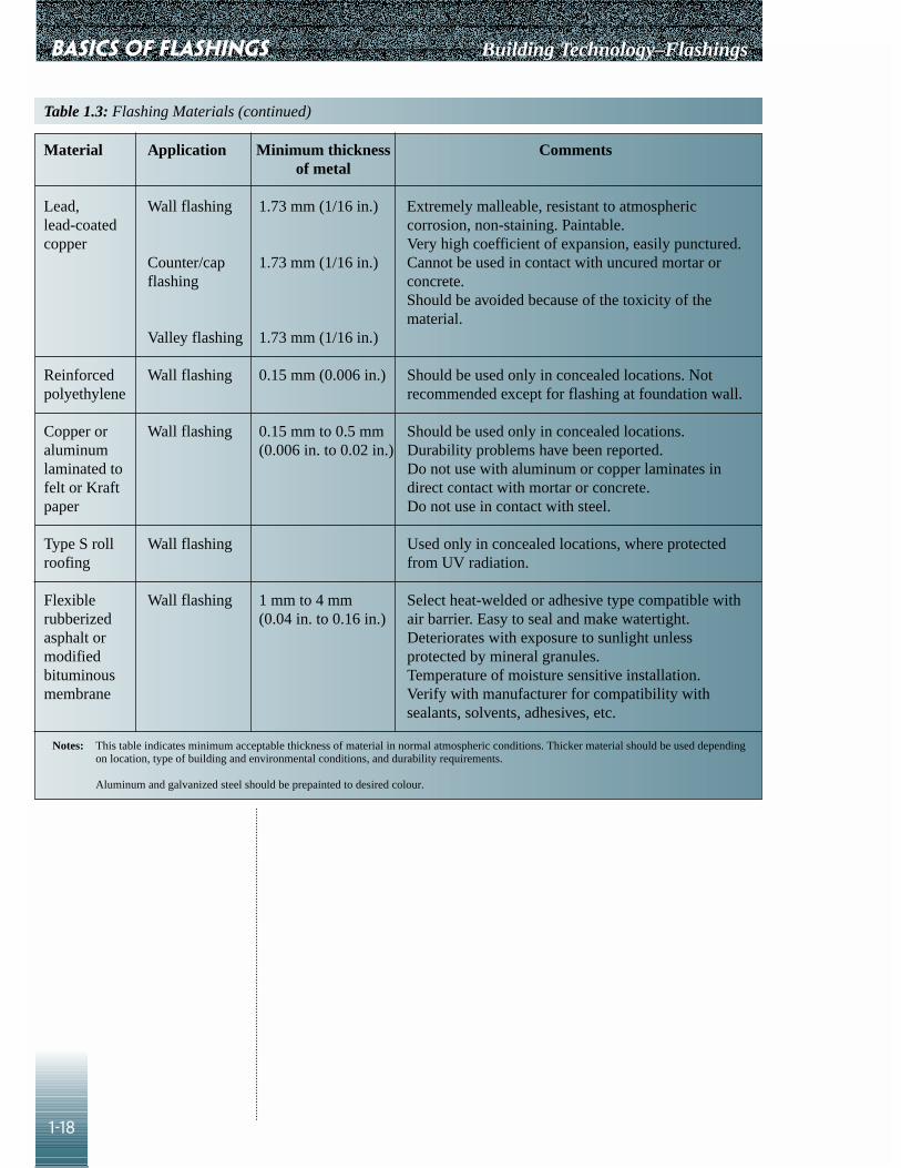
Lead, Wall flashing 1.73 mm (1/16 in.) Extremely malleable, resistant to atmospheric lead-coated corrosion, non-staining. Paintable.copper Very high coefficient of expansion, easily punctured.
Counter/cap 1.73 mm (1/16 in.) Cannot be used in contact with uncured mortar or flashing concrete.
Should be avoided because of the toxicity of thematerial.
Valley flashing 1.73 mm (1/16 in.)
Reinforced Wall flashing 0.15 mm (0.006 in.) Should be used only in concealed locations. Not polyethylene recommended except for flashing at foundation wall.
Copper or Wall flashing 0.15 mm to 0.5 mm Should be used only in concealed locations.aluminum (0.006 in. to 0.02 in.) Durability problems have been reported.laminated to Do not use with aluminum or copper laminates in felt or Kraft direct contact with mortar or concrete.paper Do not use in contact with steel.
Type S roll Wall flashing Used only in concealed locations, where protected roofing from UV radiation.
Flexible Wall flashing 1 mm to 4 mm Select heat-welded or adhesive type compatible with rubberized (0.04 in. to 0.16 in.) air barrier. Easy to seal and make watertight.asphalt or Deteriorates with exposure to sunlight unlessmodified protected by mineral granules.bituminous Temperature of moisture sensitive installation.membrane Verify with manufacturer for compatibility with
sealants, solvents, adhesives, etc.
Notes: This table indicates minimum acceptable thickness of material in normal atmospheric conditions. Thicker material should be used dependingon location, type of building and environmental conditions, and durability requirements.
Aluminum and galvanized steel should be prepainted to desired colour.
Table 1.3: Flashing Materials (continued)

Building Technology–Flashings
2-1
Introduction
The CAD details in this chapter are based on the principles of flashing designwhich are explained in Chapter 1. Each detail is accompanied by anexplanation and a new design aid: checklists for the designer and the builder.There may be repetition of written material from one detail to the other. Thisis intentional. The purpose of this is to make details self-sufficient so that,where possible, the reader will not need to refer to other details.
The details selected are those commonly found in residential construction.These details illustrate some of the best practices in flashing design andconstruction. Emphasis of the details is only on the flashings. Othercomponents of the building are shown for context and are not completelydetailed in many instances.
Where flashing details are illustrated using built-up roofing, they may beadapted for other roofing membranes, using the principles illustrated.
The details are such that a professional designer can modify them to makethem conform to the local climate and construction practices; aesthetic,performance and structural criteria; and cost factors. Therefore, CMHCcannot in any way guarantee the performance of the flashings illustrated. Theprofessional designer must assume all liability in the use and modification ofthese details.
Each building has its own particular difficult joint conditions. Best Practiceadvice is to pay special attention to drawing these details, as studies haveshown that the absence of design details is one of the most common causes ofwarranty claims. To help the designer, a guide to the use of the CAD CDRom is included in Chapter 5.
Chapter 2
DETAILS

DETAILS Building Technology–Flashings
2-2
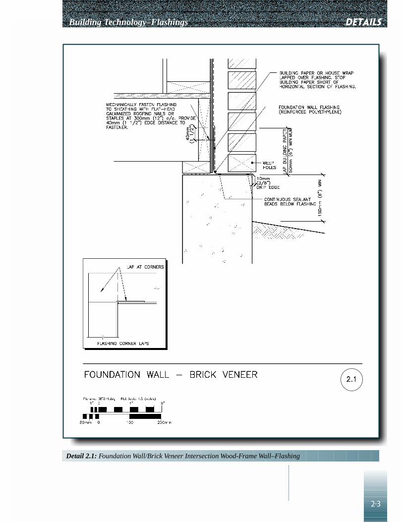
Detail 2.1–FoundationWall/Brick Veneer IntersectionWood-frame Wall–Flashing
PurposeTo intercept water flowing down the rainscreen wall cavity and direct it to theoutside, and to redirect water flowing down the exterior face of the wall toflow away from the foundation wall.
How It Works
• Moisture may enter the cavity as a result of:• rain penetration through the veneer• water vapour diffusion• leakage of moist air from the interior
• Building paper or house wrap acts as a barrier to moisture within thecavity. Moisture will drain to the bottom of the wall where it is interceptedby the flashing and directed to the exterior through the weepholes.
• The flashing is extended beyond the face of the foundation wall and formsa drip edge to break the surface tension, to shed water away from the wallsurface below.
• End dams are provided at openings in the wall, such as for doors orwindows, at changes in the wall assembly, and at steps in the foundationwall, to prevent water inside the cavity from flowing into other assemblycomponents or into the building interior.
• The drip-edge projection will also give an indication that flashing has beeninstalled. Generally, metal provides a more effective drip edge thanflexible membranes. Membrane flashings are also more susceptible tophysical damage and deterioration from UV radiation. A compromise maybe achieved by using a strip of sheet metal as the drip edge, lapped with amembrane through-wall flashing sealed to the metal.
• Dissimilar metals in contact result in galvanic corrosion. Aluminumcorrodes in contact with concrete and mortar.
Designer Checklist
❑ A continuous flashing with a drip-edge projection to shed water awayfrom the foundation wall is specified.
❑ Flexible membrane flashings are shown to be secured to the sheathing bycorrosion-resistant mechanical fasteners.
❑ Avoid placing aluminum in contact with concrete and mortar. Avoidplacing dissimilar metals in contact with each other.
❑ Mechanical fasteners are specified at regular intervals, maximum 300 mm(12 in.) on centre, to ensure tight contact between the flashing and thesheathing.
Builder Checklist
❑ Flashing is installed before the building paper or house wrap is installed. ❑ Building paper or house wrap is stopped short of the horizontal leg of the
flashing to avoid wicking up water.❑ The flashing is fastened to the wall sheathing at the specified intervals to
get a tight fit.
Building Technology–Flashings
2-3
DETAILS
Detail 2.1: Foundation Wall/Brick Veneer Intersection Wood-Frame Wall–Flashing

DETAILS Building Technology–Flashings
2-4
❑ Joints in the flashing are properly lapped (minimum 100 mm [4 in.]) andsealed.
❑ The flashing is continuous and lapped at all corners.❑ If flexible membrane flashing is used:
• Joints are free of fish mouths.• The flashing is folded up without cutting.• There are no folds where water can collect.• The edge protruding from the bottom of the foundation wall is not cut
off.• A 10 mm (0.38 in.) drip edge is provided.
❑ End dams are provided and the end of the flashing is turned up and madewatertight. Fold up the flashing if it is a membrane, without cutting it.
❑ For metal flashings, a break is provided by turning up the end and sealingit to the upturn at the back by soldering; sealing with a sealant; or a strip ofmembrane adhered on all sides.
Detail 2.2–Stepped FoundationWall–Masonry Veneer
PurposeTo intercept water within the rainscreen wall and direct it to the outside, andto redirect water, flowing down the exterior face of the wall, away from thefoundation wall.
How It Works
• Moisture may enter the cavity as a result of:• rain penetration through the veneer• water vapour diffusion• leakage of moist air from the interior
• Moisture drains to the bottom of the cavity wall where it is intercepted bythe flashing and directed to the exterior through the weepholes.
• Dissimilar metals in contact result in galvanic corrosion. Aluminumcorrodes in contact with concrete and mortar.
• In the detail shown, the air barrier is a membrane type and is located onthe exterior face of the back up wall. The flashing and air barriermembrane are installed on the exterior face of the sheathing, with the airbarrier lapped over the flashing. The membrane flashing is, in turn, lappedover a strip of metal flashing to form a drip.
• The flashing extends beyond the exterior face of the foundation wall. Thedrip breaks the surface tension, to shed water away from the wall.
• End dams are provided at openings in the wall, such as for doors orwindows, at changes in the wall assembly, and at steps in the foundationwall, to prevent water inside the cavity from flowing into other assemblycomponents or into the building interior.
Designer Checklist
❑ Avoid placing aluminum in contact with concrete and mortar. Avoidplacing dissimilar metals in contact with each other.

Building Technology–Flashings
2-5
DETAILS
Detail 2.2: Stepped Foundation Wall–Masonry Veneer

DETAILS Building Technology–Flashings
2-6
❑ A continuous flashing with a drip-edge projection to shed water awayfrom the foundation wall is specified. Metal provides a more effective dripedge than flexible membranes. Membrane flashings are also moresusceptible to physical damage and deterioration from UV radiation. Acompromise is achieved by using a strip of sheet metal as the drip edge,lapped and sealed by the membrane flashing.
❑ A separate through-wall flashing is shown, or an air barrier membranemay be used as through-wall flashing.
Builder Checklist
❑ If the air barrier is located on the inside face of the wall cavity, it iscontinuously sealed to the slab edge. Some types of membrane flashingmay be used as part of the air barrier system.
❑ The main air barrier is lapped over the flashing to ensure continuity. ❑ Joints in the flashing are properly lapped (minimum 100 mm [4 in.]) and
sealed.❑ If flexible membrane flashing is used:
• Joints are free of fish mouths.• The exposed edges are NOT cut off if no metal drip edge is used.
❑ End dams are provided at changes in the wall assembly, and the end of theflashing is turned up and made watertight. Fold up the flashing if it is amembrane, without cutting it.
❑ For metal flashings, a break is provided by turning up the end and sealingit to the upturn at the back by soldering; sealing with a sealant; or a strip ofmembrane adhered on all sides.
Detail 2.3�–Precast WindowSill – Wood-frame Wall
Detail 2.3�–Flashing/Sill Types
PurposeTo intercept water that has penetrated below the sill and redirect it to theoutside, away from the wall below. The flashing is not required but is stillrecommended if the sill consists of a single piece of precast concrete, stoneor metal.
How It Works
• Window sills are subject to more severe exposure than vertical wallsections because rain, snow and ice accumulate there. Water is absorbedthrough pores in the sill material units and mortar joints or flows downthrough cracks.
• A continuous, waterproof flashing is required below jointed sills to preventsaturation of the veneer below, which may result in efflorescence andfreeze-thaw damage.
• Dissimilar metals in contact result in galvanic corrosion. Aluminumcorrodes in contact with concrete and mortar.
• The flashing is sloped to drain to the exterior face of the wall and extendsbeyond it to form a drip edge to break the surface tension, to shed wateraway from the masonry, where it would otherwise result in staining.

Building Technology–Flashings
2-7
DETAILS
Detail 2.3a: Precast Window Sill–Wood-Frame Wall

DETAILS Building Technology–Flashings
2-8
• End dams are provided at the jambs of the wall opening at the sill toprotect adjacent bricks from saturation, and in the flashing below the sill toprevent water flowing into the wall assembly.
• The underside of the sill must be provided with a drip slot which serves asa drip edge, preventing water from flowing back to the face of the wall bybreaking the surface tension.
Designer Checklist
❑ Upturns at the end of the sill, steps in lug sills, drip deflectors or a tooledbead of sealant are required to prevent water from running off the sides ofthe sill and penetrating into the brick. Designers should note that sealantsrequire frequent maintenance and are less durable.
❑ Provide a drip slot on the underside of precast or stone sills.❑ Avoid placing aluminum in contact with concrete and mortar. Avoid
placing dissimilar metals in contact with each other.❑ Flashing materials are to be continuous across the opening, without joints.❑ A continuous drip-edge projection is specified to shed water away from
the wall below. Metal provides a more effective drip edge than flexiblemembranes. Membrane flashings are more susceptible to physical damageand deterioration from UV radiation.
❑ Flexible membrane flashings are shown to be secured to the sheathing bymethods recommended by manufacturers, such as adhesives or mechanicalfasteners.
❑ Corrosion-resistant mechanical fasteners are specified at regular intervals,maximum 300 mm (12 in.) on centre, to ensure tight contact between theflashing and the sheathing.
Builder Checklist
❑ Joints in the flashing are avoided.• If joints in the flashing cannot be avoided in large openings, they are
lapped (a minimum 100 mm [4 in.]) and sealed. ❑ The flashing is sloped to drain outward. ❑ The drip slot is located beyond the exterior face of the veneer.❑ If end dams are provided at the jambs of the sill using sealant, the sealant
beads are extended up 100 mm (4 in.) and tooled to direct water away.❑ The flashing is extended beyond the face of the wall below to form a drip. ❑ The flashing is extended beyond the jambs of the opening. ❑ If end dams are required, the end of the flashing is turned up and made
watertight. ❑ If membrane flashings are used:
• The exposed drip edges are not cut off.• The flashing is folded without cutting. • There are no folds or sags where water can collect.
❑ For metal flashings, a break is provided by turning up the end and sealingit to the upturn at the back by soldering; sealing with a sealant; or a strip ofmembrane adhered on all sides.

Building Technology–Flashings
2-9
DETAILS
Detail 2.3b: Flashing/Sill Types

DETAILS Building Technology–Flashings
2-10
Detail 2.4–Metal WindowSill/Extruded Aluminum Sillwith Rain Deflector
PurposeTo intercept water on the horizontal surface and redirect it away from thewall below.
How It Works
• Window sills are subject to more severe exposure than vertical wallsections because rain, snow and ice accumulate there.
• A continuous, extruded metal sill acts as a waterproof barrier. It preventssaturation of the veneer below, which would result in efflorescence andfreeze-thaw damage. However, the metal sill ends must be carefullydetailed to prevent water penetration into the wall.
• Dissimilar metals in contact result in galvanic corrosion. Aluminumcorrodes in contact with concrete and mortar.
• The sill is typically anchored to the underside of the window frame. It issloped to drain away from the window and extends beyond the exteriorface of the wall below to form a drip. The drip-edge projection breaks thesurface tension to shed water away from the wall below.
Designer Checklist
❑ Avoid placing aluminum in contact with concrete and mortar. Avoidplacing dissimilar metals in contact with each other.
❑ If an aluminum sill is desired to match the window frame, the underside ofthe sill, in contact with mortar, is coated with a bituminous coating, or animpervious flexible membrane is installed directly underneath thealuminum sill to separate it from the mortar.
❑ Flashing materials are shown to be continuous across the opening, withoutjoints. • If joints cannot be avoided, at corners for example, or if the width of the
opening is very large, “cap flashings” are specified to be installed overthe joint.
• The cap flashings are shown to follow the profile of the sill down to theunderside of the drip.
• Cap flashings are shown to be minimum 200 mm (8 in.) wide, centredover the joint, and sealed to the sill on all sides with a continuous beadof sealant.
• If mechanical fasteners are required, they are shown to be installed onone side of the joint to allow movement, due to expansion andcontraction of the materials.
❑ Select sealants according to the following:• What should be the life expectancy of this joint? • Is the sealant appropriate for the substrate, movement requirements and
exposure? • Have joint dimensions been specified? • Does the substrate need priming? • Has a bond breaker or backer rod been specified?

Building Technology–Flashings
2-11
DETAILS
Detail 2.4: Metal Window Sill/Extruded Aluminum Sill with Rain Deflector

DETAILS Building Technology–Flashings
2-12
Builder Checklist
❑ If aluminum sills are used, the aluminum is not in direct contact withmortar.
❑ The sill is extended beyond the face of the wall below, to form a drip.❑ The sill is properly sloped away from the window and overhangs the wall
by a minimum 25 mm (1 in.).❑ When sealants are required, ensure:
• The weather and temperature are appropriate for applying the sealant.• The surface has been cleaned and primed.• The substrate and primer materials are compatible.• The sealant joint width and depth are appropriate for the expected
movement. ❑ The bond breaker or backup rod is of the correct size and properly
positioned.❑ The sealant has been tooled to fill the joint, without bubbles or other
defects.❑ Joints have been tested to ensure that the sealant will adhere.
Detail 2.5–Jointed PrecastWindow Sill–Brick Veneer
PurposeTo intercept water that has penetrated below the precast sill and redirect it tothe outside, away from the wall below. The flashing is not required but is stillrecommended if the sill consists of a single piece of precast concrete, stoneor metal.
How It Works
• Window sills are subject to more severe exposure than vertical wallsections because rain, snow and ice accumulate there. Water is absorbedthrough pores in the sill material units and mortar joints or flows downthrough cracks.
• Dissimilar metals in contact result in galvanic corrosion. Aluminumcorrodes in contact with concrete and mortar.
• A continuous, waterproof flashing is required below jointed sills to preventsaturation of the veneer below, which would result in efflorescence andfreeze-thaw damage.
• The sill and flashing are sloped to drain away from the window. Theflashing extends beyond the wall to form a drip edge to break the surfacetension and to shed water away from the masonry, where it wouldotherwise result in staining.
• The underside of the sill must be provided with a drip slot to serve thesame purpose as the drip edge.
• End dams are provided and the end of the flashing is turned up and madewatertight. Fold up the flashing if it is a membrane, without cutting it.
• Membrane flashings are more susceptible to physical damage anddeterioration from UV radiation.

Building Technology–Flashings
2-13
DETAILS
Detail 2.5: Jointed Precast Window Sill–Brick Veneer

DETAILS Building Technology–Flashings
2-14
Designer Checklist
❑ Upturns at the end of the sill, steps in lug sills, drip reflectors or a tooledbead of sealant are required to prevent water from running off the sides ofthe sill and penetrating into the brick. Designers should note that sealantsrequire frequent maintenance and are less durable.
❑ Avoid placing aluminum in contact with concrete and mortar. Avoidplacing dissimilar metals in contact with each other.
❑ Flashing materials are shown to be continuous across the opening, withoutjoints.
❑ Select sealants according to the following:• What should be the life expectancy of this joint? • Is the sealant appropriate for the substrate, movement requirements and
exposure? • Have joint dimensions been specified? • Does the substrate need priming? • Has a bond breaker or backer rod been specified?
❑ A continuous drip-edge projection is specified to shed water away fromthe wall below. Metal provides a more effective drip edge than flexiblemembranes. Membrane flashings are more susceptible to physical damageand deterioration from UV radiation.
❑ Flashings are shown to be secured to the back-up structure or windowframe with corrosion-resistant fasteners.
❑ Corrosion-resistant mechanical fasteners are specified at regular intervals,maximum 300 mm (12 in.) on centre, to ensure tight contact between theflashing and the backing.
Builder Checklist
❑ Joints in the flashing are avoided.• If joints in the flashing cannot be avoided in large openings, they are
lapped (minimum 100 mm [4 in.]) and sealed.❑ The sill and flashing are sloped to drain away from the window and from
the jambs of the opening. ❑ For membrane flashings, there are no sags or folds where water can
accumulate. ❑ The flashing is extended beyond the exterior face of the wall below to
form a drip. ❑ The edges of membrane flashings are not cut off.❑ The flashing is extended beyond the jambs of the opening.❑ For membrane flashings, the flashing is folded without cutting.❑ For metal flashings, a break is provided by turning up the end and sealing
it to the upturn at the back by soldering; sealing with a sealant; or a strip ofmembrane adhered on all sides.
❑ The drip slot is located beyond the exterior face of the veneer.❑ If end dams are provided at the jambs of the sill using sealant, the sealant
beads are extended up 100 mm (4 in.) and tooled to direct water away.
Building Technology–Flashings
2-15
❑ Sealant joints• How will this joint work?• Is the weather and temperature appropriate for applying the sealant
application?• Has the surface been cleaned and primed?• Are the substrate and primer materials compatible?• Is the joint width and depth appropriate for the expected movement?• Is the bond breaker or backer rod of the correct size and properly
positioned?• Has the sealant been tooled to fill the joint without bubbles or other
defects?• Test to ensure that sealant adheres.
DETAILS

DETAILS Building Technology–Flashings
2-16
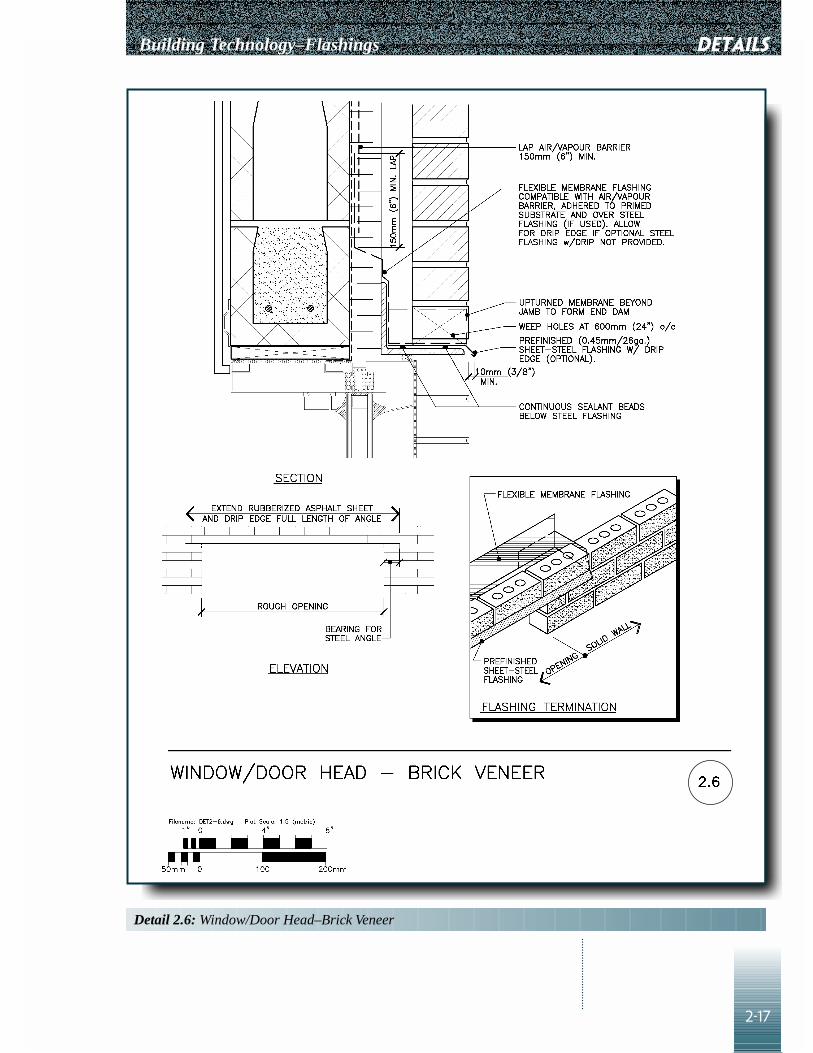
Detail 2.6–Window/DoorHead–Brick Veneer
PurposeTo intercept water within cavity of the rainscreen wall and direct it to theoutside, and to redirect water flowing down the exterior face of the wall toflow away from the wall opening.
How It Works
• Moisture may enter the cavity as a result of:• rain penetration through the veneer• water vapour diffusion• leakage of moist air from the interior
• Moisture drains to the bottom of the cavity wall where it is intercepted bythe flashing and directed to the exterior through weepholes.
• In the detail shown, the primary air barrier is a membrane type and islocated on the exterior face of the concrete block. The separate through-wall membrane flashing is, in turn, lapped over a strip of metal flashing,forming a drip edge to break the surface tension, to shed water away fromthe wall opening.
• Dissimilar metals in contact result in galvanic corrosion. Aluminumcorrodes in contact with concrete and mortar.
• The flashing extends beyond the exterior face of the wall.• End dams are typically provided at the ends of the lintel to prevent water
from flowing into the adjacent wall assembly.
Designer Checklist
❑ Avoid placing aluminum in contact with concrete and mortar. Avoidplacing dissimilar metals in contact with each other.
❑ A continuous flashing with a drip-edge projection is specified to shedwater away from the foundation wall. Metal provides a more effective dripedge than flexible membranes. Membrane flashings are also moresusceptible to physical damage and deterioration from UV radiation. Acompromise is achieved by using a strip of sheet metal as the drip edge,lapped and sealed by the membrane flashing.
❑ Specify that flashing joints must be lapped and sealed (minimum 100 mm[4 in.]).
Builder Checklist
❑ If joints in the flashing cannot be avoided because of the width of opening,seal the joints.
❑ For flexible membrane flashing, ensure:• The joints are free of fish mouths.• The exposed edges are not cut off.• The flashing is folded without cutting. • There are no folds where water can collect.
❑ For metal flashings, a break is provided by turning up the end and sealingit to the upturn at the back by soldering; sealing with a sealant; or a strip ofmembrane adhered on all sides.
Building Technology–Flashings
2-17
DETAILS
Detail 2.6: Window/Door Head–Brick Veneer

DETAILS Building Technology–Flashings
2-18
Detail 2.7–Shelf Angle atConcrete Slab/BrickVeneer/CMU
PurposeTo intercept water within the cavity of the rainscreen wall and direct it to theoutside, and to redirect water flowing down the exterior face of the wall toflow away from the wall surface below.
How It Works
• Moisture may enter the cavity as a result of:• rain penetration through the veneer• water vapour diffusion• leakage of moist air from the interior
• Moisture will drain to the bottom of the cavity wall, where it is interceptedby the flashing and directed to the exterior.
• In the detail shown, the air barrier is a membrane type and is located onthe exterior face of the concrete block. It is lapped over a separatemembrane through-wall flashing, which is, in turn, lapped over a strip ofmetal flashing to form a drip.
• Dissimilar metals in contact result in galvanic corrosion. Aluminumcorrodes in contact with concrete and mortar.
• Minimum longitudinal laps of 100 mm (4 in.) are recommended.• A metal drip edge is recommended because a drip formed by extending
the membrane past the brick face is not durable, owing to degradation bysunlight (UV radiation).
• The flashing extends beyond the exterior face of the wall below. It forms adrip edge to break the surface tension, to shed water away from the wall.
• End dams are provided at changes in the wall assembly to prevent waterflowing into other assembly components or into the building interior.
• This detail also applies to some steel stud construction, in which the airbarrier is located inside the wall cavity. The flashing and air barriermembrane are then installed on the exterior face of the sheathing.

Building Technology–Flashings
2-19
DETAILS
Detail 2.7: Shelf Angle at Concrete Slab–Brick Veneer/CMU

DETAILS Building Technology–Flashings
2-20
Designer Checklist
❑ Avoid placing aluminum in contact with concrete and mortar. Avoidplacing dissimilar metals in contact with each other.
❑ A continuous flashing with a drip-edge projection is specified to shedwater away from the foundation wall. Metal provides a more effective dripedge than flexible membranes. Membrane flashings are also moresusceptible to physical damage and deterioration from UV radiation. Acompromise is achieved by using a strip of sheet metal as the drip edge,lapped and sealed by the membrane flashing.
❑ A separate through-wall flashing is shown. Some air barrier membranesmay be used as through-wall flashing.
❑ Select sealants according to the following:• What should be the life expectancy of this joint? • Is the sealant appropriate for the substrate, movement requirements and
exposure? • Have joint dimensions been specified? • Does the substrate need priming? • Has a bond breaker or backer rod been specified?
Builder Checklist
❑ Joints in the flashing are properly lapped (minimum 100 mm [4 in.]) andsealed.
❑ End dams are provided and the end of the flashing is turned up and madewatertight. Fold up the flashing if it is a membrane, without cutting it.
❑ If the shelf angle is bolted to the concrete slab, the bolts must not puncturethe flashing.
❑ Sealant joints• How will this joint work?• Is the weather and temperature appropriate for applying the sealant
application?• Has the surface been cleaned and primed?• Are the substrate and primer materials compatible?• Is the joint width and depth appropriate for the expected movement?• Is the bond breaker or backer rod of the correct size and properly
positioned?• Has the sealant been tooled to fill the joint without bubbles or other
defects?• Test to ensure that sealant adheres.

Building Technology–Flashings
2-21
❑ For flexible membrane flashing, ensure:• The joints are free of fish mouths.• The exposed edges are not cut off.• The flashing is folded without cutting. • There are no folds or sags where water can collect.
❑ For metal flashings, a break is provided by turning up the end and sealingit to the upturn at the back by soldering; sealing with a sealant; or a strip ofmembrane adhered on all sides.
DETAILS

DETAILS Building Technology–Flashings
2-22
Detail 2.8–WallPenetration–MasonryVeneer/CMU
PurposeTo intercept water from entering the cavity of the rainscreen wall at wallpenetrations.
How It Works
• Moisture may enter the cavity as a result of:• rain penetration through the veneer• water vapour diffusion• leakage of moist air from the interior
• Moisture will drain down the cavity, where it is intercepted by the flashingand directed to the exterior through weepholes provided in the exteriorface of the louvred vent.
• Dissimilar metals in contact result in galvanic corrosion.• This detail also applies to steel stud construction, in which the air barrier is
located inside the wall cavity. The flashing and the air barrier are then tobe installed on the exterior face of the sheathing.
Designer Checklist
❑ Louvred vent and duct must not be of dissimilar metals. Specify corrosion-resistant materials.
❑ Select sealants according to the following:• What should be the life expectancy of this joint? • Is the sealant appropriate for the substrate, movement requirements and
exposure? • Have joint dimensions been specified? • Does the substrate need priming? • Has a bond breaker or backer rod been specified?
Builder Checklist
❑ The louvred-vent surface is sloped down to drain water out of the cavity.❑ The air barrier membrane is sealed to all sides of the duct and the vent is
sealed to the duct.❑ Sealant joints
• How will this joint work?• Is the weather and temperature appropriate for applying the sealant
application?• Has the surface been cleaned and primed?• Are the substrate and primer materials compatible?• Is the joint width and depth appropriate for the expected movement?• Is the bond breaker or backer rod of the correct size and properly
positioned?• Has the sealant been tooled to fill the joint without bubbles or other
defects?• Test to ensure that sealant adheres.

Building Technology–Flashings
2-23
DETAILS
Detail 2.8: Wall Penetration–Masonry Veneer/CMU
DETAILS Building Technology–Flashings
2-24
Detail 2.9–Low Parapet–BrickVeneer
PurposeTo prevent water from penetrating the interior of the building, wall cavity androofing system.
How It Works
• The roofing membrane is turned up the cant, where it is lapped by aseparate membrane called the base flashing, which extends over theparapet to the exterior face of the wall. There it is fastened to the woodblocking, not to the veneer.
• This base flashing constitutes the primary waterproofing along the edge ofthe roof and the parapet wall. It may be built up of several plies of thesame material as that of the roofing membrane, or it may consist of adifferent but compatible material.
• The flashing must be adequately supported by the wood blocking becausethe top of the parapet wall can be subject to foot traffic during windowwashing and other activities requiring staging.
• The cant is used to ease the membrane into the change in direction. It isrequired for built-up roofing membranes and recommended for some othertypes of roofing membranes. A cant may not be required for some single-ply membranes. Consult the roofing manufacturer.
• The membrane base flashing is covered by metal counter flashing alongthe interior perimeter of the roof and by cap flashing over the parapet.These metal flashings protect it from impact damage and UV radiation.
• The cap flashing is sloped toward the roof to prevent water from flowingtoward the exterior face of the wall, minimizing the wetting of the veneerbelow, and protecting pedestrians at ground level.
• The metal cap flashing extends down the exterior face of the wall, at leastone brick and mortar joint, and includes a drip-edge projection to directwater draining off the metal out and away from the wall surfaces below.
• A typical S-joint detail for allowing thermal expansion and contraction ofthe metal cap flashing is shown in the insert. Only one of the metalsections (one side) is fastened to the substrate. The other side is restrainedbut allowed to move parallel with the wall due to thermal expansion andcontraction. They will perform better and have a longer service life thanjoints relying on sealant.
Designer Checklist
❑ Cap flashings are jointed to account for thermal movements of the metal.❑ S-joints in the metal flashing are specified, with no exposed fasteners.❑ Provide for differential movement between the metal flashing and the
brick veneer.❑ Roof flashings are designed to allow for easy removal during roof
replacement.
Builder Checklist
❑ Cladding and roofing trades work is coordinated.❑ Flashings are adequately protected from damage during construction.❑ There are no exposed fasteners.

Building Technology–Flashings
2-25
DETAILS
Detail 2.9: Low Parapet–Brick Veneer

DETAILS Building Technology–Flashings
2-26
Detail 2.10–Door Sill–BalconyLocation–Flashing
PurposeTo intercept water on the horizontal surface and direct it away from the wallbelow.
How It Works
• Door sills are subject to rain, snow and ice accumulation, as well as foottraffic. Extruded metal sills are ideally suited to accommodate this.
• Dissimilar metals in contact result in galvanic corrosion. Aluminumcorrodes in contact with concrete and mortar.
• A continuous, extruded metal sill acts as a waterproof flashing to interceptrainwater or snow on the horizontal surface and direct it away from thedoor.
• The door frame is supported on a raised cast-in-place concrete curb toprevent water leakage to the interior of the building.
• An impervious membrane is installed below the door frame from theexterior face of the concrete curb to the inside face of the door frame,where it is turned up. It is also turned up at the jambs of the opening. Thismembrane acts as a secondary flashing to intercept possible water leakagethrough the sill of the door frame. If the extruded sill is aluminum, themembrane also prevents contact between the concrete and the aluminum,which will otherwise deteriorate.
• The underside of the sill is typically anchored to the door frame. It issloped to drain water away from the door and extends beyond the exteriorface of the wall below forming a drip. The drip-edge projection breaks thesurface tension, to shed water away from the wall below.
• End dams are provided at the jambs of the wall opening to protect theadjacent wall assembly from water damage.
• Air barrier sealant, gasket or adhesive membrane is applied to the framesof all door, window and other penetrations to prevent air leakage throughthe wall.
Designer Checklist
❑ Avoid placing aluminum in contact with concrete and mortar. Avoidplacing dissimilar metals in contact with each other.
❑ If an aluminum sill is desired to match the door frame, ensure theunderside of the sill is not in contact with concrete. The flexible membraneflashing in the detail separates these elements. Alternatively, ensure theunderside of the sill is covered with a bituminous coating, but will notserve as a secondary flashing.
❑ Flashing materials are shown to be continuous across the opening, withoutjoints.
❑ Upturns at the end of the sill, steps in lug sills, drip reflectors or a tooledbead of sealant are required to prevent water from running off the sides ofthe sill and penetrating into the brick. Designers should note that sealantsrequire frequent maintenance and are less durable.
Builder Checklist
❑ If aluminum sills are used, the aluminum is not in direct contact withconcrete or mortar.

Building Technology–Flashings
2-27
DETAILS
Detail 2.10: Door Sill–Balcony Location–Flashing

DETAILS Building Technology–Flashings
2-28
❑ The sill is extended beyond the face of the wall below, to form a drip.❑ The sill is properly sloped away from the door, and the vertical overlap
between the sill and the wall is a minimum 25 mm (1 in.).
Detail 2.11–Sloped Roof/WallIntersection–Wood-frame
PurposeTo provide a waterproof transition between the shingled roof and the wall,preventing water penetration.
How It Works
• The stepped roof flashing or base flashing at the roof-wall intersection isinstalled in shingle fashion. It sheds water and stops it from penetrating thewall from the roof.
• A 75 mm (3 in.) height of overlap between consecutive pieces of flashingis recommended to prevent water infiltration.
• Sectional flashing reduces the thermal movement at each lap. Stepped baseflashing must be interwoven with shingles.
• The stepped counter flashing is attached only to the wall, and the lowerstepped base flashing is attached only to the roof. Differential movementsbetween the roof structure and the wall, therefore, do not affect theflashing performance.
• Wall sheathing paper acts as a moisture barrier within the wall. Lappingthe paper over the stepped flashing directs water onto the flashing.
• The stepped counter flashing shown in the detail fulfils the function ofboth through-wall and counter flashing.
• Stepped counter flashing intercepts water from inside the brick veneercavity and directs it out onto the shingled roof flashing. If through-wallflashing is omitted and a counter flashing sealed to the veneer face isinstalled, water inside the wall cavity may result in interior water leakage.
• The back and upper end of each section of stepped counter flashing isturned up to form an end dam to prevent water from flowing into the wallcavity below.
• Weepholes in the brick work allow the water to drain out.
Designer Checklist
❑ The type and thickness of flashing materials and the coordination offlashing installation are specified.
❑ Inspection is specified both at the masonry and roofing stages.❑ Weepholes in the brick work are specified at 600 mm on centre (24 in.).❑ Roof flashings are designed to allow easy removal for roof replacement.
Builder Checklist
❑ The wall masonry and roofing work are coordinated so that the flashingscan be installed in the correct order and lapped.• The shingled roof is installed before the masonry above the roof level. • The base flashing is installed at the same time as the shingles and is
interwoven with them.

Building Technology–Flashings
2-29
DETAILS
Detail 2.11: Sloped Roof/Wall Intersection–Wood-frame

DETAILS Building Technology–Flashings
2-30
• The through-wall flashing/counter flashing is installed by the masonsafter the base flashing.
❑ Back and upper slopes of stepped wall flashing are turned up into mortarjoints to form end dams.
❑ Wall flashing and base flashing are not fastened together, to allowdifferential movement.
❑ End dams are provided by folding up the ends of the flashing. ❑ For membrane flashing, the flashing is folded without cutting it, but there
are no folds where water can collect.❑ For metal flashings, a break is provided by turning up the end and sealing
it to the upturn at the back by soldering; sealing with a sealant; or a strip ofmembrane adhered on all sides.
Detail 2.12–Sloped Roof/WallIntersection–Brick Veneer
PurposeTo provide a waterproof transition where the roof is sloping away from thewall, and to intercept water flowing down the wall cavity and direct it to theoutside.
How It Works
• The flashing consists of two components: a through-wall flashing and acounter flashing.
• The through-wall flashing intercepts water flowing down the wall cavityand directs it to the outside.
• Moisture may enter the cavity as a result of:• rain penetration through the veneer• water vapour diffusion from the interior• air leakage from the interior
• Dissimilar metals in contact result in galvanic corrosion. Aluminumcorrodes in contact with concrete and mortar.
• Sheathing paper (building paper or house wrap) acts as the moisturebarrier within the wall. Lap the sheathing paper over the flashing.
• The flashing is extended beyond the face of the wall and forms a drip toshed water away from the wall surface below, as shown. Alternatively, it islapped over the counter flashing.
• The roof underlay is turned up the vertical wall surface a minimum of100 mm (4 in.).
• The shingles are continuous up to the intersection with the wall.• A metal counter flashing is installed to direct water away from the roof-
wall intersection. The counter flashing is terminated inside the brickveneer wall, into a reglet left by the mason. It is fastened or wedged inplace.
• The reglet should be located a minimum of 150 mm (6 in.) up the wall,directly below, or in the first mortar joint below the through-wall flashing.This is to prevent water penetration through the brick and into the wallcavity below.

Building Technology–Flashings
2-31
DETAILS
Detail 2.12: Sloped Roof/Wall Intersection–Brick Veneer

DETAILS Building Technology–Flashings
2-32
Designer Checklist
❑ A continuous flashing with a drip-edge projection is specified to shedwater away from the foundation wall. Metal provides a more effective dripedge than flexible membranes. Membrane flashings are also moresusceptible to physical damage and deterioration from UV radiation. Acompromise is achieved by using a strip of sheet metal as the drip edge,lapped and sealed by the membrane flashing.
❑ Flexible membrane flashings are shown to be secured to the sheathingwith mechanical fasteners, maximum 300 mm (12 in.) on centre, ensuringtight contact between flashing and sheathing. Use compatible adhesivesand primers.
❑ Avoid placing aluminum in contact with concrete and mortar. Avoidplacing dissimilar metals in contact with each other.
❑ Metal counter flashings with locked S-joints are specified. They willperform better and have a longer service life than joints relying on sealant.
❑ If ice damming or snow accumulation are concerns, specify a self-sealingcomposite membrane as underlay. An additional base flashing is generallynot required because the roof is sloped away from the wall and water isshed naturally.
❑ Through-wall flashing is shown to be extended to lap over the counterflashing taking into account the traditional sequencing of masonry androofing work.
❑ Roof flashings are designed to allow easy removal for roof replacement.
Builder Checklist
❑ The through-wall flashing is properly fastened to the sheathing to get atight fit.
❑ Through-wall flashings are installed before the moisture barrier isinstalled.
❑ The moisture barrier is lapped over the flashing but stops short of thehorizontal leg, to avoid wicking up water.
❑ Joints in the through-wall flashing are lapped (minimum 100 mm [4 in.])and sealed.
❑ For flexible membrane flashings:• The joints are free of fish mouths. • Through-wall flashing is used.• The exposed edge is not cut off, unless a metal drip edge is used, as in
the detail.
Detail 2.13�–RoofPenetrations–Brick Chimney
detail 2.13�–RoofPenetrations–Upper Side ofBrick Chimney
detail 2.13�–RoofPenetrations–Brick ChimneySaddle
PurposeTo prevent water from penetrating at the chimney/roof intersection.

Building Technology–Flashings
2-33
DETAILS
Detail 2.13a: Roof Penetrations–Brick Chimney

DETAILS Building Technology–Flashings
2-34
How It Works
• The flashing at the low side of the chimney base is lapped over the courseof shingles immediately below the chimney, to effectively shed water.
• The shingled stepped base flashing at the side of the chimney is theninterwoven with each course of asphalt roof shingles, to provide watershedding. The base flashing must extend up the wall a minimum of 75 mm(3 in.) but is not fastened to it.
• The counter flashing is installed in a reglet in the masonry and fastened orwedged in place. Minimum embedment is 25 mm (1 in.). The joint issealed with a sealant. Minimum overlap between the base and counterflashing is 75 mm (3 in.).
• Separate shingled base flashing and stepped counter flashing allowdifferential movement between chimney and roof structures.
• The saddle drawn in Detail 2.13c directs water away from the upper partof the chimney, where it may otherwise accumulate. All joints should besoldered to make the saddle watertight.
• Although the Building Code calls for a saddle only for chimneys widerthan 750 mm [30 in.], it is good practice to use saddles for all chimneysand other locations where the roof slopes down into a vertical projection.
• Prefinished sheet-steel flashing can be used. A longer life can be obtainedby using stainless steel or copper.
• Although it is commonly done, it is not good practice to only seal thecounter flashing to the face of the masonry without turning it into a reglet.This type of joint is very susceptible to water leakage as it is completelyexposed and the sealant will require continuous maintenance.
• Annual inspection and regular maintenance of sealants is required toprotect against rain penetration.
Designer Checklist
❑ Specify no aluminum, which reacts with the alkali in mortar.❑ A saddle is specified for chimneys wider than 750 mm (30 in.).❑ For additional water protection, a self-sealing waterproofing sheet or roll
roofing is specified as an underlay around the chimney, under the saddle,and up the slope of the roof.
❑ Roof flashings are designed to allow easy removal for roof replacement.❑ Select sealants according to the following:
• What should be the life expectancy of this joint? • Is the sealant appropriate for the substrate, movement requirements and
exposure? • Have joint dimensions been specified? • Does the substrate need priming? • Has a bond breaker or backer rod been specified?

Building Technology–Flashings
2-35
DETAILS
Detail 2.13b: Roof Penetrations–Upper Side of Brick Chimney
DETAILS Building Technology–Flashings
2-36
Builder Checklist
❑ Masonry, roofing and sheet-metal work coordination is critical.❑ The stepped base flashing is installed at the same time as the shingles and
is interwoven with them.❑ Stepped counter flashing is built into the masonry at the time of chimney
construction or is installed into reglets left by the mason.❑ All joints in the saddle, through-wall flashing and flashing at the base of
the chimney are soldered or sealed watertight.❑ Sealant joints
• How will this joint work?• Is the weather and temperature appropriate for applying the sealant
application?• Has the surface been cleaned and primed?• Are the substrate and primer materials compatible?• Is the joint width and depth appropriate for the expected movement?• Is the bond breaker or backer rod of the correct size and properly
positioned?• Has the sealant been tooled to fill the joint without bubbles or other
defects?• Test to ensure that sealant adheres.

Building Technology–Flashings
2-37
DETAILS
Detail 2.13c: Roof Penetrations–Brick Chimney Saddle

DETAILS Building Technology–Flashings
2-38
Detail 2.14–Damp-proofFlashing–Exposed MasonryWall
PurposeTo intercept water immediately below the coping and direct it to the exterior,preventing leaks into the wall assembly below.
How It Works
• Water from rain, snow or ice penetrates the masonry wall below, throughjoints or cracks in the coping.
• Dissimilar metals in contact result in galvanic corrosion. Aluminumcorrodes in contact with concrete and mortar.
• A continuous, waterproof membrane is required below jointed masonry orstone copings to prevent saturation of the wall assembly below, whichcould result in efflorescence and freeze-thaw damage.
• The membrane extends beyond the face of the wall forming a drip, to shedwater away from the wall below, where it may otherwise result indegradation of the joints and staining.
• Some membranes can self-seal around penetrations through themembrane, such as for dowels. Others require sealing with a materialcompatible with the membrane.
• The coping itself is sloped away from the most critical face, where waterflow would affect pedestrians or the wall assembly below.
• The underside of the coping should have a drip reglet to break the surfacetension, to prevent water from flowing back onto the wall.
Designer Checklist
❑ Avoid placing aluminum in contact with concrete and mortar. Avoidplacing dissimilar metals in contact with each other.
❑ Membrane materials are shown to be continuous across all openings. • Type of sealant or mastic around penetrations is specified.
❑ A drip-edge projection is specified to shed water away from the wallbelow.
❑ Ensure holes are provided at bottom of wall cavity.
Builder Checklist
❑ Joints in the membrane are avoided. • If joints cannot be avoided, they are lapped (minimum 100 mm [4 in.])
and sealed.❑ Stagger the joints in the flashing with joints in the coping.❑ The flashing is sealed around penetrations before the coping is installed. ❑ The flashing is extended beyond the face of the wall below to form a drip.
Do not cut off the exposed edges of membrane flashings.

Building Technology–Flashings
2-39
DETAILS
Detail 2.14: Damp-proof Flashing–Exposed Masonry Wall
DETAILS Building Technology–Flashings
2-40
Detail 2.15–FoundationWall–Stucco Veneer
PurposeTo redirect water flowing down the exterior face of the wall to flow awayfrom the foundation wall.
How It Works
• The flashing serves both as a drip edge and plaster guard or metal trim. • The flashing is extended beyond the face of the foundation below the wall
and forms a drip to shed water away from the foundation wall surfacebelow.
Designer Checklist
❑ Galvanized or stainless steel flashing and fasteners are specified.Aluminum will react with the stucco cement.
❑ Mechanical fasteners are specified at regular intervals, maximum 300 mm(12 in.) on centre, for tight contact between the flashing and the sheathing.
Builder Checklist
❑ Flashing is installed before the building paper or housewrap is installed. ❑ Building paper or house wrap and stucco lath are lapped over the vertical
leg of the flashing.❑ The flashing is properly fastened to the wall sheathing at sufficient
intervals to get a tight fit.❑ Joints in the flashing are lapped (minimum 100 mm [4 in.]) and sealed.❑ The bottom of the flashing is extended below the top of the foundation
wall to cover the sill joint.❑ Flashing is continuous at the corners.❑ End dams are provided at openings.❑ The horizontal leg of flashing is mitred at the corners.❑ Vertical legs are lapped at the corner to provide continuity at the corners.

Building Technology–Flashings
2-41
DETAILS
Detail 2.15: Foundation Wall–Stucco Veneer
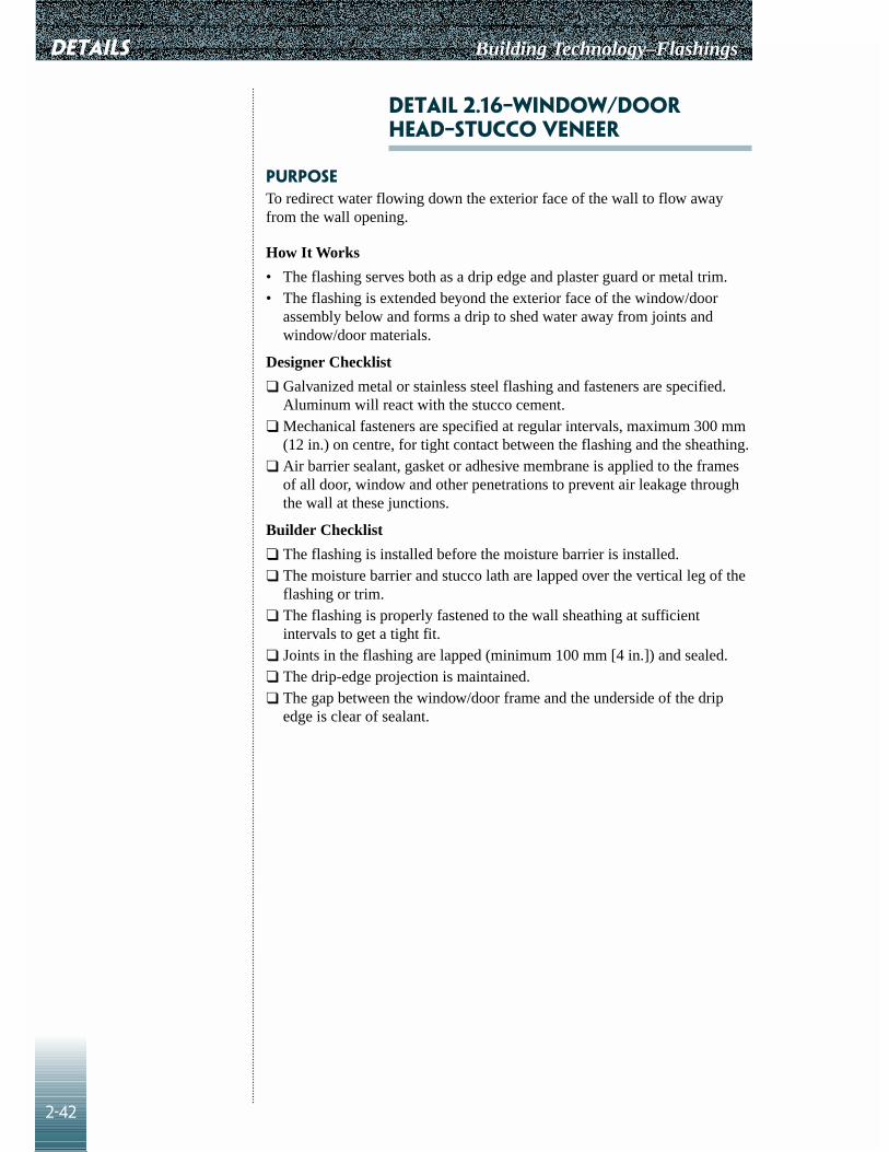
DETAILS Building Technology–Flashings
2-42
Detail 2.16–Window/DoorHead–Stucco Veneer
PurposeTo redirect water flowing down the exterior face of the wall to flow awayfrom the wall opening.
How It Works
• The flashing serves both as a drip edge and plaster guard or metal trim. • The flashing is extended beyond the exterior face of the window/door
assembly below and forms a drip to shed water away from joints andwindow/door materials.
Designer Checklist
❑ Galvanized metal or stainless steel flashing and fasteners are specified.Aluminum will react with the stucco cement.
❑ Mechanical fasteners are specified at regular intervals, maximum 300 mm(12 in.) on centre, for tight contact between the flashing and the sheathing.
❑ Air barrier sealant, gasket or adhesive membrane is applied to the framesof all door, window and other penetrations to prevent air leakage throughthe wall at these junctions.
Builder Checklist
❑ The flashing is installed before the moisture barrier is installed. ❑ The moisture barrier and stucco lath are lapped over the vertical leg of the
flashing or trim.❑ The flashing is properly fastened to the wall sheathing at sufficient
intervals to get a tight fit.❑ Joints in the flashing are lapped (minimum 100 mm [4 in.]) and sealed.❑ The drip-edge projection is maintained. ❑ The gap between the window/door frame and the underside of the drip
edge is clear of sealant.

Building Technology–Flashings
2-43
DETAILS
Detail 2.16: Window/Door Head–Stucco Veneer

DETAILS Building Technology–Flashings
2-44
Detail 2.17–FoundationWall–Vinyl, Aluminum Siding
PurposeTo intercept water behind the siding and direct it to the outside, away fromthe foundation wall.
How It Works
• Moisture may enter the cavity as a result of:• rain penetration through the siding• water vapour diffusion• leakage of moist air from the interior
• Building paper or house wrap (inside the cavity) acts as a barrier to rainpenetration into the inner layer of the wall.
Designer Checklist
❑ A horizontal siding application is shown, with a combination of starterstrip and bottom siding panel to direct the water to the outside.
❑ For vertical siding applications, a separate base trim is specified to act asflashing and also to close the openings at the bottom of the siding profile.
❑ The flashing is shown to have a drip-edge projection.❑ Mechanical fasteners are specified at regular intervals, maximum 300 mm
(12 in.) on centre, to ensure tight contact between the starter strip/flashingand the sheathing.
❑ Ensure that corners and end dams at openings are detailed.
Builder Checklist
❑ Flashing is installed before the moisture barrier is installed. ❑ Building paper or house wrap is lapped over the vertical leg of starter
strip/flashing and fasteners.❑ The starter strip/flashing is properly fastened to the wall sheathing at
sufficient intervals to provide a tight fit.❑ Joints in the starter strip/flashing are properly lapped (minimum 100 mm
[4 in.]).❑ The bottom of the starter strip/flashing is extended below the top of the
foundation wall, a minimum of 75 mm (3 in.), to cover the joint.❑ For vertical siding applications, the joint between the flashing and the
bottom of the siding is left open for drainage.❑ Flashing is continuous at the corners.❑ End dams are provided at openings.

Building Technology–Flashings
2-45
DETAILS
Detail 2.17: Foundation Wall–Vinyl, Aluminum Siding

DETAILS Building Technology–Flashings
2-46
Detail 2.18–Foundation Wall–AtPrecast Steps
PurposeTo limit water damage to the wood structure.
How It Works
• The wall sheathing below the door sill and the joint with the foundationwall is treated with a waterproof, flexible, self-sealing compositemembrane to prevent water leaking into the building.
• The exposed section of the flexible membrane is covered by metal flashingto protect it from impact damage and UV radiation. Unexposed wallsections may be protected with other materials, such as protection board.
• The drip at the door sill limits the amount of water flowing back to theface of the wall by breaking the surface tension.
• Provide sealant at the underside of the door sill to stop air infiltration.• The flashing prevents water penetration and staining of the wall below the
door sill.• Dissimilar metals in contact result in galvanic corrosion. Aluminum
corrodes in contact with concrete and mortar.
Designer Checklist
❑ For vinyl and aluminum siding, the sill flashing is specified to bepreformed by the siding manufacturer.
❑ For wood siding, prefinished sheet steel is specified. ❑ Specify colour and thickness of sheet metal.❑ Avoid placing aluminum in contact with concrete and mortar. Avoid
placing dissimilar metals in contact with each other.
Builder Checklist
❑ Do not fill the drip-edge projection with sealant.❑ The flexible membrane is protected.

Building Technology–Flashings
2-47
DETAILS
Detail 2.18: Foundation Wall–At Precast Steps

DETAILS Building Technology–Flashings
2-48
Detail 2.19–Window Sill–Wood,Vinyl, Aluminum Siding
PurposeTo limit the amount of water flowing back onto the wall.
How It Works
• The sill/drip flashing at the underside of the window sill limits the amountof water flowing back to the face of the wall, by breaking the surfacetension. Sealant at the underside of the window will eliminate airinfiltration.
• The flashing limits staining of the wall below the window, as well aslimiting water penetration behind the exterior cladding.
• The flashing also acts as a closing trim, particularly for vinyl andaluminum siding.
• Air barrier sealant, gasket or adhesive membrane is applied to the framesof all door, window and other penetrations to prevent air leakage throughthe wall at these junctions.
• Dissimilar metals in contact result in galvanic corrosion. Aluminumcorrodes in contact with concrete and mortar.
Designer Checklist
❑ For vinyl and aluminum siding, the flashing is specified to be preformedby the siding manufacturer.
❑ For wood siding, prefinished sheet steel is specified, complete with dripedge.
❑ Colour and thickness of sheet metal are specified. ❑ Avoid placing aluminum in contact with concrete and mortar. Avoid
placing dissimilar metals in contact with each other.
Builder Checklist
❑ If joints in the flashing cannot be avoided, the flashing sections are lapped(minimum 100 mm [4 in.]) and sealed.
❑ Do not fill the drip edge projection with sealant.

Building Technology–Flashings
2-49
DETAILS
Detail 2.19: Window Sill–Wood, Vinyl, Aluminum Siding

DETAILS Building Technology–Flashings
2-50
Detail 2.20–Window/DoorHead–Wood, Vinyl, AluminumSiding
PurposeTo intercept water behind the siding and direct it to the outside, and toredirect water flowing down the face of the wall to flow away from the wallopening.
How It Works
• Moisture may enter the cavity as a result of:• rain penetration through the siding• water vapour diffusion• leakage of moist air from the interior
• Some of the moisture will drain through the weepholes or gaps at thebottom of each siding panel.
• An additional head trim flashing is required at the head of thewindow/door to direct water further outward, beyond the thickness of thewindow/door frame, which protrudes from the face of the wall.
• Dissimilar metals in contact result in galvanic corrosion. Aluminumcorrodes in contact with concrete and mortar.
Designer Checklist
❑ For vinyl and aluminum siding:• The head trim/flashing is typically preformed by the siding
manufacturer.• The flashing projection is specified.
❑ For wood siding, prefinished galvanized sheet steel is specified, completewith drip edge.
❑ Colour and thickness of sheet steel are specified. ❑ Avoid placing aluminum in contact with concrete and mortar. Avoid
placing dissimilar metals in contact with each other.❑ Mechanical fasteners are specified at regular intervals, maximum 300 mm
(12 in.) on centre, for tight contact between the head flashing and thesheathing.
❑ Air barrier sealant, gasket or adhesive membrane is applied to the framesof all door, window and other penetrations to prevent air leakage throughthe wall at these junctions.
Builder Checklist
❑ Flashing is installed before the starter strip and moisture barrier areinstalled.
❑ The moisture barrier is lapped over the vertical leg of the headtrim/flashing or over the starter strip.
❑ The head flashing is fastened to the wall sheathing at sufficient intervals toobtain a tight fit.
❑ Joints in the head flashing are avoided. • If joints cannot be avoided, they are lapped (minimum 100 mm [4 in.])
and sealed.❑ The drip edge is kept free of sealant.
For vertical siding applications, the joint between the flashing and thebottom of the siding is left open for drainage.
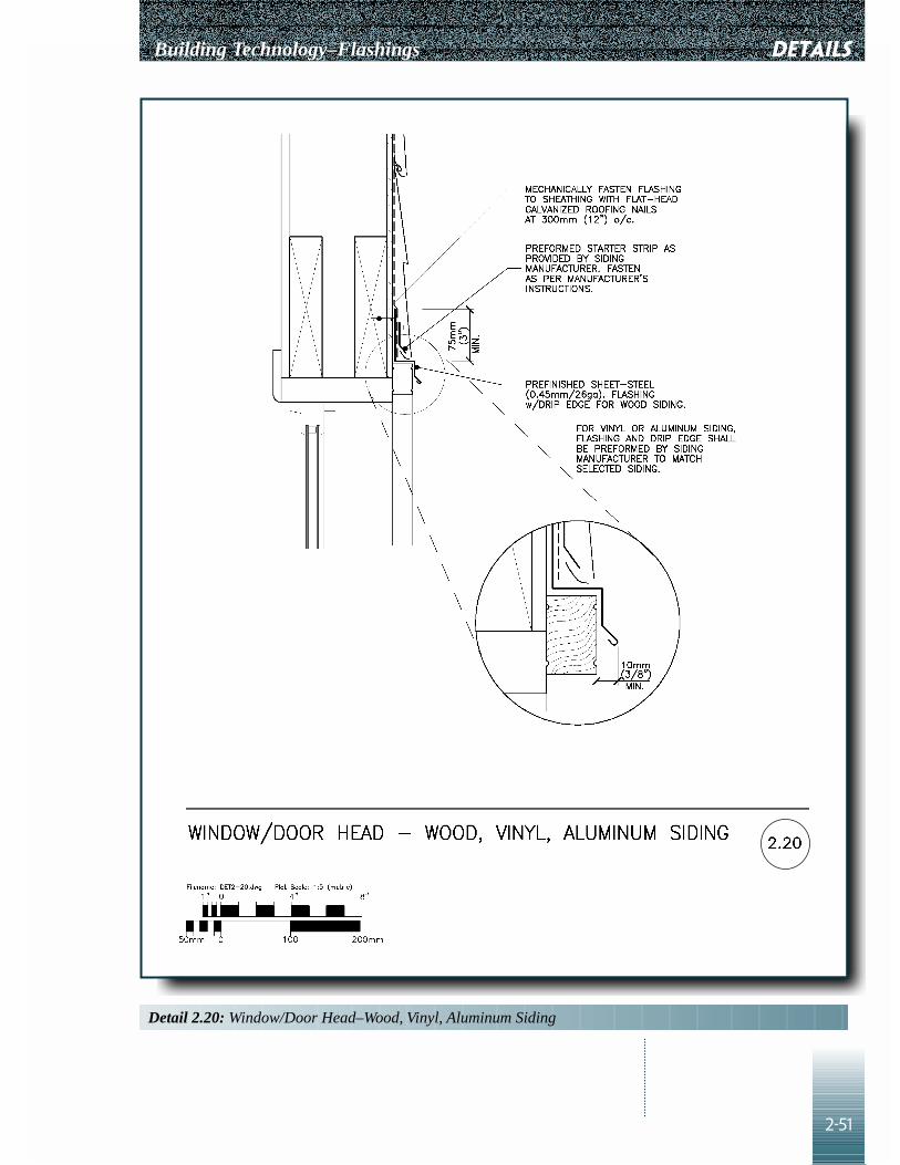
Building Technology–Flashings
2-51
DETAILS
Detail 2.20: Window/Door Head–Wood, Vinyl, Aluminum Siding

DETAILS Building Technology–Flashings
2-52
Detail 2.21–Overhang–Wood,Vinyl, Aluminum Siding
PurposeTo intercept water behind the siding and direct it to the outside.
How It Works
• Moisture may enter the cavity as a result of:• rain penetration through the siding• water vapour diffusion from the interior• air leakage from the interior
• Wall sheathing (building paper or house wrap) acts as a moisture barrierwithin the wall.
• In horizontal siding applications, some of the moisture behind the sidingwill drain out through the weepholes at the bottom of each siding panel.Moisture draining to the bottom of the wall is intercepted and directed tothe outside by the combination of starter strip and bottom siding panel,which fulfil the function of flashing.
• The location of the weepholes, on the outer face of the siding panel,ensures that water drains out away from the wall surface below.
• Dissimilar metals in contact result in galvanic corrosion. Aluminumcorrodes in contact with concrete and mortar.
Designer Checklist
❑ A horizontal siding application includes a combination of starter strip andbottom siding panel to direct the water to the exterior. Consider the use ofan additional flashing complete with drip edge to limit the amount ofwater flowing back along the soffit which may result in staining anddeterioration of the soffit.For vertical siding applications:• A separate base trim is required to act as flashing and also to close the
openings at the bottom of the siding profile. • The flashing has a drip-edge projection.
❑ Flashings may be prefinished metal, cut and shaped on site, or vinyl oraluminum preformed by the siding manufacturer. Avoid placing aluminumin contact with concrete and mortar. Avoid placing dissimilar metals incontact with each other.
❑ Mechanical fasteners are specified at regular intervals, maximum 300 mm(12 in.) on centre, to ensure tight contact between the starter strip/flashingand the sheathing.
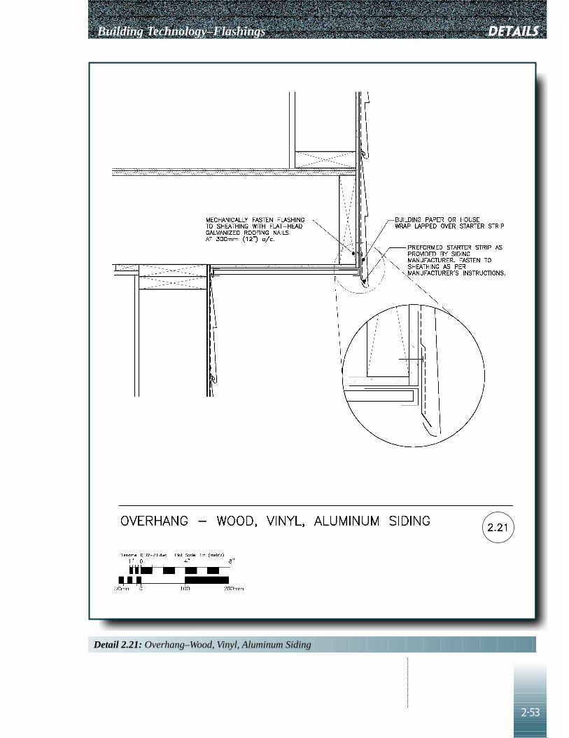
Building Technology–Flashings
2-53
DETAILS
Detail 2.21: Overhang–Wood, Vinyl, Aluminum Siding
DETAILS Building Technology–Flashings
2-54
Builder Checklist
❑ Flashings must be installed before the starter strip and building paper areinstalled.
❑ If no additional drip flashing is used, the building paper is lapped over thestarter strip/flashing and fasteners.
❑ The starter strip/flashing is fastened to the wall sheathing at sufficientintervals to get a tight fit.
❑ Joints in the flashing are lapped (minimum 100 mm [4 in.]) and sealed.❑ Alignment of the flashing is coordinated with soffit positioning. ❑ The flashing covers the exterior edge of the soffit.
Detail 2.22�–Flat Roof/WallAbove (Terrace)–Wood, Vinyl,Aluminum Siding
DETAIL 2.22�–Flat Roof/DoorSill (Terrace)–Wood, Vinyl,Aluminum Siding
PurposeTo provide a waterproof transition between the roofing membrane and thewall.
How It Works
• Roofing membrane is turned up onto the wall to prevent water penetration,in the event of ponding or snow and ice accumulation at the roof-walljunction.
• Membrane base flashing extends from the roof membrane up under thewall sheathing paper to prevent water behind the cladding penetratingbehind the roof membrane upturn.
• Metal counter flashing protects the base flashing and roof membraneupturn from impact and deterioration due to exposure to UV radiation.
Designer Checklist
❑ Ensure details around doors are shown on the drawings.❑ Specify membrane base flashing type and installation method according to
type of roof membrane. ❑ Type, thickness and colour of base and counter flashing materials are
specified.❑ Metal flashing connections are detailed to allow for easy removal for
inspection of base flashing and for roof replacement.❑ Slope of terrace structure is specified to drain water away from the wall.

Building Technology–Flashings
2-55
DETAILS
Detail 2.22a: Flat Roof/Wall Above (Terrace)–Wood, Vinyl, Aluminum Siding

DETAILS Building Technology–Flashings
2-56
Builder Checklist
❑ Membrane flashing/base flashing is installed in accordance with roofingspecifications.
❑ Roof membrane upturn, base flashing and counter flashing are installedbefore wall sheathing paper and wall siding are installed.
❑ The counter flashing is fastened to the wall above the roof membraneupturn to reduce the likelihood of leaks.

Building Technology–Flashings
2-57
DETAILS
Detail 2.22b: Flat Roof/Door Sill (Terrace)–Wood, Vinyl, Aluminum Siding

DETAILS Building Technology–Flashings
2-58
Detail 2.23–Medium/HighParapet–Prefinished Veneer
PurposeTo prevent water from penetrating the interior of the building, wall cavity androofing system.
How It Works
• The roofing membrane is turned up the cant, where it is lapped by aseparate base flashing membrane, which extends over the parapet to theexterior face of the wall. There it is fastened to the wood blocking.
• This base flashing membrane constitutes the primary waterproofing alongthe edge of the roof and the parapet wall. It may be built up of severalplies of the same material as that of the roofing membrane, or it mayconsist of a different but compatible material.
• The flashing must be adequately supported by the wood blocking becausethe top of the parapet wall can be subject to foot traffic during windowwashing and other activities requiring staging.
• The cant is used to ease the membrane into the change in direction. It isrequired for built-up roofing membranes and recommended for other typesof roofing membranes.
• The membrane base flashing is covered by metal counter flashing alongthe interior perimeter of the roof and by cap flashing over the parapet toprotect it from impact damage and UV radiation.
• The cap flashing is sloped toward the roof to prevent water from flowingtoward the exterior face of the wall, thus minimizing wetting of the veneerbelow, and protecting pedestrians at ground level.
• The metal cap flashing extends down the exterior face of the wall, aminimum of 100 mm (4 in.) below the wood blocking. It includes a drip-edge projection to direct water draining off the metal out and away fromthe wall surfaces below.
Designer Checklist
❑ Cap flashings must be jointed to account for thermal movements of themetal.
❑ S-joints in the metal flashing are specified, with no exposed fasteners.❑ Ensure adequate provision for differential movement between the metal
flashing and the exterior wall cladding.❑ Roof flashings are designed to allow easy removal for roof replacement.
Builder Checklist
❑ Coordination is required between cladding and roofing trades.❑ Flashings are adequately protected from damage during construction.❑ If metal siding is used as the exterior cladding, closure strips matching the
siding profile are also provided to cover the underside of the woodblocking.

Building Technology–Flashings
2-59
DETAILS
Detail 2.23: Medium/High Parapet–Prefinished Veneer

DETAILS Building Technology–Flashings
2-60
Detail 2.24–Flat Roof EdgeFlashing
PurposeTo prevent water penetrating the interior of building, wall cavity and roofingsystem.
How It Works
• The roofing membrane is turned up the cant, where it is lapped by aseparate base flashing membrane, which extends over the roof edge to theexterior face of the wall. There it is fastened to the wood blocking.
• This base flashing constitutes the primary waterproofing along the edge ofthe roof and the parapet wall. It may be built up of several plies of thesame material as that of the roofing membrane, or it may consist of adifferent but compatible material.
• The flashing must be adequately supported by the wood blocking becausethe top of the parapet wall can be subject to foot traffic during windowwashing and other activities requiring staging.
• The cant is used to ease the membrane into the change in direction. It isrequired for built-up roofing membranes and recommended for other typesof roofing membranes.
• The membrane base flashing is covered by a metal cap flashing to protectit from impact damage and UV radiation.
• The cap flashing is sloped toward the roof to prevent water flowing towardthe exterior face of the wall, thus minimizing wetting of the veneer below,and protecting pedestrians at ground level.
• The metal cap flashing extends down the exterior face of the wall, aminimum of 100 mm (4 in.) below the wood blocking. It includes a drip-edge projection to direct water draining off the metal out and away fromthe wall surfaces below.
Designer Checklist
❑ Cap flashings are shown to be jointed to account for thermal movementsof the metal.
❑ S-joints in the metal flashing are specified, with no exposed fasteners.❑ Adequate provision is made for differential movement between the metal
flashing and the exterior wall cladding.❑ Roof flashings are designed to allow for easy removal during roof
replacement.
Builder Checklist
❑ Coordination is required between cladding and roofing trades.❑ Flashings are adequately protected from damage during construction.❑ If metal siding is used as the exterior cladding, provide closure strips
matching the siding profile to cover the underside of the wood blocking.

Building Technology–Flashings
2-61
DETAILS
Detail 2.24: Flat Roof Edge Flashing

DETAILS Building Technology–Flashings
2-62
Detail 2.25–Sloped ShingleRoof Eave
PurposeTo support the shingle edge and to provide a drip edge to prevent water fromrunning back underneath the shingles and down along the fascia and soffit.
How It Works
• A preformed eaves flashing/drip edge is installed under the starter courseof the asphalt shingle roofing.
• Extension of flashing supports edge of shingles. If eavestroughs are used,the flashing edge also helps to direct water into troughs.
• Fascia flashing retains the soffit, protects the fascia board, and provides adrip edge at the bottom edge to direct water away from the soffit, helpingto reduce maintenance requirements.
• Dissimilar metals in contact result in galvanic corrosion. Aluminumcorrodes in contact with concrete and mortar.
Designer Checklist
❑ Eavestroughing is detailed, if required.❑ Type, thickness and colour of material is specified.❑ If the fascia is wood, detail the eavestrough to allow easy removal for
repainting.
Builder Checklist
❑ Fascia flashing is nailed on first.❑ Eaves flashing/drip edge and roofing follows fascia flashing, and conceals
fasteners. ❑ Eaves protection membrane laps over above flashing drip edge.❑ Eaves flashing is secured with nails, typically 200 mm (8 in.) on centre.❑ Nails and flashing are compatible.

Building Technology–Flashings
2-63
DETAILS
Detail 2.25: Sloped Shingle Roof Eave

DETAILS Building Technology–Flashings
2-64
Detail 2.26�–Ridge Vent–SlopedShingle Roof
PurposeTo provide roof ventilation while preventing water penetration.
How It Works
• The ridge vent is a prefabricated metal profile, designed to provide roofventilation while protecting the top of shingled roofs. Select ridge ventscarefully, ensuring that they are designed to shed water and to preventwater and snow penetration. They are also provided with insect screens toprevent entry of insects. This detail must be selected with caution since theroof and wall orientation may predispose the detail to wind-driven rainentry, or blockage by snow drifts.
• The ridge vent’s metal legs are lapped over the top edge of the shingles onboth sides of the roof. They are embedded in a continuous bed of mastic toprevent water wicking up through capillary action. They are fastened usingnails, complete with gasket washers to prevent leakage.
• The bottom leg of the ridge vent is turned up to provide rigidity, but theupturns are provided with drainage holes.
• Various types of ridge vents are available, including some designed to beshingled over. Ventilation is then provided through baffled openings on thesides of the ridge vent. Refer to CSA Standard CAN3-A93-M92, “NaturalAirflow Ventilators for Buildings.”
Builder Checklist
❑ Ensure the roof sheathing has a gap at the top to allow ventilation, but thegap should be small enough that the shingles are still supported.
❑ Joints are avoided. If joints are required because of the length of the roof,appropriate connectors are used to seal the joints and prevent water frompenetrating.
❑ The ends of the ridge vents are closed off.

Building Technology–Flashings
2-65
DETAILS
Detail 2.26a: Ridge Vent–Sloped Shingle Roof

DETAILS Building Technology–Flashings
2-66
Detail 2.26�–Roof to WallVent–Sloped Shingle Roof
PurposeTo provide roof ventilation while preventing water penetration.
How It Works
• The ridge vent is a prefabricated metal profile, designed to provide roofventilation while protecting the top of shingled roofs. Select ridge ventscarefully, ensuring that they are designed to shed water and to preventwater and snow penetration. This detail must be selected with cautionsince the roof and wall orientation may predispose the detail to wind-driven rain entry or leakage by snow drifts.
• Vent holes are provided with insect screens to prevent entry of insects.• The bottom leg of the ridge vent laps over the top edge of the shingle on
both sides of the roof. It is embedded in a continuous bed of mastic toprevent water wicking up through capillary action, and fastened usingnails complete with gasket washers to prevent leakage.
• The bottom leg of the ridge vent is typically turned up to provide rigidity,but the upturns are provided with drainage holes.
• At the roof-wall intersection, the roof vent acts as a wall flashing. Theupper leg of the roof vent is lapped by the sheathing paper and the exteriorwall finish.
• The sheathing paper acts as the moisture barrier within the wall. Lappingit over the top of the flashing directs water outward.
Designer Checklist
❑ Finish and colour of the roof vent are specified.❑ Connection of the metal counter flashing is detailed to allow for easy
removal.
Builder Checklist
❑ The roof sheathing has a gap at the top to allow for ventilation, but the gapis small enough that the shingles are still supported.
❑ Joints are avoided, but if joints are required because of the length of theroof, appropriate connectors that allow for thermal movement are used toseal joints and prevent water penetration.
❑ The ends of the ridge vents are closed off.❑ Coordinate roofing and exterior cladding work.❑ If the exterior wall cladding above the roof is masonry, the upper leg of the
roof vent is sealed to the exterior face of the masonry by turning the upperleg of roof vent into a reglet.

Building Technology–Flashings
2-67
DETAILS
Detail 2.26b: Roof to Wall Vent-Sloped Shingle Roof

DETAILS Building Technology–Flashings
2-68
Detail 2.27�–Skylight–Horizontal Section A
DETAIL 2.27��Skylight–VerticalSection B1
detail 2.27�–Skylight–VerticalSection B2 with Saddle
detail 2.27�–Skylight–ShowingRubberized Asphalt SheetUnderlay
detail 2.27��Skylight–IsometricShowing Base Flashing OverUnderlay
detail 2.27�–Skylight–IsometricShowing Saddle and StepFlashing
PurposeTo shed water off the skylight to prevent water from penetrating through theskylight and roof connections, especially in areas with high snow buildup.
How It Works
• Flashing is an integral component of the skylight. It must be designed toseal and shed water. Flashing membranes are particularly critical ineliminating potential damage of ice damming and water buildup in placeswith significant accumulation of snow. Sealants should never be relied onto maintain a seal.
• Water draining down the roof surface is intercepted by the flashing at thehead of the skylight (head flashing) and flows down along the stepflashing on the sides of the skylight. The head flashing laps over the stepflashing on the sides of the skylight and projects beyond the latter, as inthe chimney detail.
• For additional water protection, a self-sealing rubberized asphalt sheet isused as an underlay around the skylight.
• Step flashing is interwoven with the shingles and fastened to the skylightframe only.
• Step flashing and counter flashing each allow differential movementbetween the skylight and roof.
• In cold weather, snow melting from heat loss around the skylight drainsdown and can refreeze downstream, causing ice damming. Watersubsequently builds up behind the ice dam, ultimately penetrating belowthe shingles. A rubberized asphalt sheet prevents water leakage resultingfrom this condition (see Detail 2.27d).

Building Technology–Flashings
2-69
DETAILS
Detail 2.27a: Skylight–Horizontal Section A

DETAILS Building Technology–Flashings
2-70
Detail 2.27b: Skylight–Vertical Section B1

Building Technology–Flashings
2-71
DETAILS
Detail 2.27c: Skylight–Vertical Section B2 With Saddle

DETAILS Building Technology–Flashings
2-72
Detail 2.27d: Skylight–Showing Rubberized Asphalt Sheet Underlay

Building Technology–Flashings
2-73
DETAILS
Detail 2.27e: Skylight–Isometric Showing Base Flashing Over Underlay

DETAILS Building Technology–Flashings
2-74
• Ice damming can be minimized by reducing heat loss from the roof andskylight wall. Rigid insulation, with a minimum thermal resistanceequivalent to that in the exterior walls of the building, should be provided(see Details 2.27a, b, c). If the skylight walls are inclined, insulation with athermal resistance equivalent to the roof should be considered. Thisreduces the amount of snow melt that could cause ice damming.
• A roof curb is provided to raise the base of the skylight above rooflevel. The flatter the roof, the higher the curb should be. The table onDetail 2.27a provides recommended curb heights.
• To provide further protection against water penetration, a saddle isprovided (see Detail 2.27c) to divert the water from around the skylight.This detail should be used for skylights more than 750 mm wide andfor roof slopes of 3:12 or less. Saddle design and flashing requirementsfor around the saddle are similar to those of the chimney saddle inDetail 2.13c.
Designer Checklist
❑ Select skylights employing corner details that do not rely on sealants.❑ Two types of skylights are typically available:
• with integral curb and flashing, ready to be installed directly on roofdeck
• with a curb frame to be installed on a site-built curb.❑ Flashing details will vary. Carefully follow the manufacturer’s
instructions.❑ The skylight manufacturer’s flashing kit details are used, particularly
corner treatments.❑ A saddle or similar structure on the upper part of the roof above the
skylight is detailed to direct water away from the head of the skylight.❑ If plastic or PVC skylights are used in cold climates, they must incorporate
special features to allow movement due to thermal expansion andcontraction differentials with the structure to which they are attached.
❑ Keep skylights away from walls or other protrusions through the roof,such as parapets, chimneys or high walls, which might encourage snowaccumulation.
❑ Roof flashings are designed to allow easy removal for roof replacement.
Builder Checklist
❑ Sequence of construction:• Install curb.• Place self-sealing rubberized asphalt sheet underlay. Make continuous
around corners.• Turn the underlay up the curb and over the top of the curb.• Place prefinished steel head flashing.• If saddle is used, install saddle.• Install shingles.• Install step flashing interwoven with shingles.• Install counter flashing.• Install skylight.

Building Technology–Flashings
2-75
DETAILS
Detail 2.27f: Skylight–Isometric Showing Saddle and Step Flashing

DETAILS Building Technology–Flashings
2-76
• Install interior insulation and finish.• Ensure that ventilated space is provided under the roof around the
skylight.• Use the flashing kit designed by the skylight manufacturers.• Ensure that flashing is continuous around the entire perimeter of the
skylight.
Detail 2.28–Open Valley–AsphaltShingle Roof
PurposeTo provide a waterproof transition at the intersection of two sloped surfacesof a shingle roof where the flashing is left exposed.
How It Works
• The flashing provides primary waterproofing in the valley.• The flashing extends up the slope, underneath the shingles, to provide
waterproofing in case of ice damming or snow buildup.• Along the valley, the top corners of the shingles are clipped and the edge is
sealed to the flashing with plastic cement to minimize water flowunderneath the shingles and direct it toward the centre of the valley.
• If roll roofing is used, the mineral surface of the top layer sheds waterfrom the surface and also protects against UV radiation.
Designer Checklist
❑ Specify sheet metal or a minimum of two layers of roll roofing ormodified bitumen membrane for open valley flashing.
❑ Colour of roll roofing or colour and thickness of sheet metal flashing arespecified.
❑ Consider a self-sealing composite membrane underneath the valleyflashing as additional protection.
Builder Checklist
❑ Valley flashing is completed before the shingles are installed.❑ Do not use fasteners on the shingles closer than 200 mm (3 in.) of the
centre line of the valley.❑ A 50 mm (2 in.) triangular piece is cut off at the top corners of shingles
along the valley. ❑ Embed the valley edge of the shingles in a 75 mm (3 in.) wide bed of
asphalt plastic cement.

Building Technology–Flashings
2-77
DETAILS
Detail 2.28: Open Valley–Asphalt Shingle Roof

DETAILS Building Technology–Flashings
2-78
Detail 2.29–Closed and WovenValley Flashing
PurposeTo provide a waterproof transition at the valley intersection of two slopedsurfaces of a shingle roof where the flashing is covered.
How It Works
• Two methods are used to close the valley with shingles, but the installationof the valley is similar.
• Shingles provide primary waterproofing by shedding water down theslope.
• The valley flashing extends up the slope underneath the shingles toprovide waterproofing in case of ice damming or snow buildup.
• Asphalt shingles can crack when bent through the valley. The flashing isprovided to prevent water penetrating through these cracks.
Designer Checklist
❑ Do not use closed valleys when using rigid shingles on slopes of less than1:12.
❑ Materials used for closed valley flashings are sheet metal; a self-sealingcomposite membrane; or one layer of Type S or Type M roll roofing, withthe mineral surface face down.
Builder Checklist
❑ Ensure valley flashing is completed before shingles are installed.❑ Do not use fasteners to fasten shingles through flashing within 150 mm (6
in.) of the centre line of the valley.❑ Avoid cold weather work that will result in the undesirable cracking of
shingles.❑ For closed cut valleys, a 50 mm (2 in.) triangular piece is cut off at the top
corner of the upper layer of shingles along the valley. Embed the valleyedge of the shingles in a 75 mm (3 in.) wide bed of asphalt plastic cement.
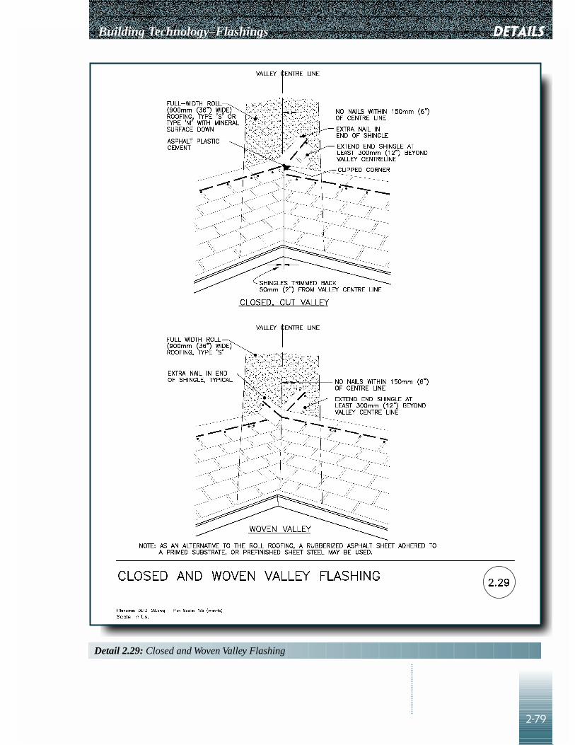
Building Technology–Flashings
2-79
DETAILS
Detail 2.29: Closed and Woven Valley Flashing

DETAILS Building Technology–Flashings
2-80
Detail 2.30–Roof Area Divider
PurposeTo maintain a waterproof roof assembly and prevent water leakage at atransition in the roof or to limit the size of a continuous roofing membrane.
How It Works
• Roof dividers are typically installed at:• changes in direction of the roof deck• changes in composition of the roof deck assembly and membrane• joining of a new roofing system into an existing membrane• locations that limit the size of a continuous roofing membrane and
therefore help minimize the effect of shrinkage and other differentialdimensional changes
• Joints always constitute weak points in an assembly. Therefore it is goodpractice to locate them on top of a curb to limit the potential of waterleakage.
• The curb is built directly on the roof deck and is anchored to it. Theroofing membrane is turned up the cant, where it is lapped by a separatebase flashing membrane that extends over the top of the curb. There it islapped by the base flashing membrane from the other side of the curb.
• The base flashing membranes constitute the primary waterproofing alongand over the curb. They may be built up of several plies of the samematerial as that of the roofing membrane, or may consist of a different butcompatible material. If a built-up system is used, a minimum of one plyper side continues over the top of the wall to the other side of the curbwhere it is fastened. It is interwoven with the ply from the other side of thecurb. The top of the curb is covered with a minimum of two plies.
• The flashing must be adequately supported by the framing of the dividerwall because the top of the curb can be subject to foot traffic.
• The cant is used to ease the membrane into the change in direction. It isrequired for built-up roofing membranes and recommended for other typesof roofing membranes.
• The membrane base flashing is covered by metal counter flashing alongthe sides of the curb and a metal cap flashing over the wall to protect itfrom impact damage and UV radiation.
• The metal counter flashing is fastened on both sides of the curb, close tothe top.
• The cap flashing is sloped to one side to prevent water from ponding ontop of it.

Building Technology–Flashings
2-81
DETAILS
Detail 2.30: Roof Area Divider

DETAILS Building Technology–Flashings
2-82
Designer Checklist
❑ Locations of divider walls and roof slopes are specified. ❑ The divider walls do not prevent the flow of water to drains. ❑ Cap flashings are specified to be jointed to account for thermal movements
of the metal. ❑ S-joints in the metal flashing are specified, with no exposed fasteners.❑ Roof flashings are designed to allow for easy removal during roof
replacement.
Builder Checklist
❑ The roof areas are properly sloped so that divider walls are located at highpoints and do not restrict the flow of water to the drains.
❑ The flashings over the curb are protected from damage duringconstruction.
❑ There are no exposed fasteners.
Detail 2.31–Building MovementJoint at Roof
PurposeTo maintain a waterproof roof assembly and prevent water leakage at atransition in the roof.
How It Works
• The building movement joint in the roofing system reflects a movementjoint in the building structure, allowing the building structure to movewithout damage to the roof.
• Joints always constitute weak links in an assembly. Therefore it is goodpractice to locate them on top of a curb.
• The curb is built directly on the roof deck and is anchored to it. Along anexpansion joint, the curb consists of two separate frames, one on each sideof the expansion joint, with a gap for movement in between.
• On each side of the curb, the roofing membrane is turned up the cant,where it is lapped by a separate base flashing membrane, which extends tothe top of the curb.
• This base flashing constitutes the primary waterproofing along the curb. Itmay be built up of the same number of plies of the same material as that ofthe roofing membrane or it may consist of a different but compatiblematerial.
• The flashing must be adequately supported by the framing of the curbbecause the top of the curb can be subject to foot traffic.
• The cant is used to ease the membrane into the change in direction. It isrequired for built-up roofing membranes and recommended for other typesof roofing membranes.
• A different but compatible flexible membrane is lapped over the baseflashing and is fastened just below the top of the curb. This membraneincorporates a loop between the two rows of fasteners to allow formovement.

Building Technology–Flashings
2-83
DETAILS
Detail 2.31: Building Movement Joint at Roof

DETAILS Building Technology–Flashings
2-84
• The membrane base flashing is covered by metal counter flashing alongthe sides of the curb and metal cap flashing over the curb to protect it fromimpact damage and UV radiation.
• The metal counter flashing is fastened on both sides of the curb, close tothe top. The cap flashing is sloped to one side to prevent water ponding.
• One side of the junction between counter flashing and cap flashing (theright hand side on the detail) is designed to allow movement, bothhorizontal and vertical. Other configurations are possible.
Designer Checklist
❑ Roof slopes are specified to ensure expansion joint curbs do not interceptthe flow of water.
❑ A flexible membrane is specified over an expansion joint curb. Theflexible membrane is specified to be elastomeric and able to withstandmovement.
❑ Cap flashings are shown to be jointed to allow for thermal movements ofthe metal.
❑ S-joints in the metal flashing are specified, with no exposed fasteners.❑ Roof flashings are designed to allow for easy removal during roof
replacement.
Builder Checklist
❑ The roof areas are properly sloped to ensure that the curbs are not locatedat low points and do not restrict the flow of water.
❑ The flashings over the curb are protected from damage duringconstruction.
❑ There are no exposed fasteners.❑ Ensure that movement is possible between metal counter flashing and cap
flashing.
Detail 2.32–Firewall for SlopedShingle Roof
PurposeTo provide a waterproof transition between the shingled roof and the firewall,as well as over the wall itself to control water penetration.
How It Works
• The stepped base flashing at the sides of the projecting wall is interwovenwith each course of roof shingles to shed water. The base flashing mustextend up the wall a minimum of 100 mm (4 in.) but is not fastened to it.
• The rubberized asphalt sheet is the flexible waterproof component of thewall. It is typically a self-sealing composite membrane. It is continuousover the wall and is lapped over the shingled base flashing to direct wateronto it. Joints in the membrane should be properly lapped and madewatertight.
• The flexible membrane is covered by metal counter flashing along thesides of the wall and metal cap flashing over the wall to protect it fromimpact damage and UV radiation. The metal flashing is not waterproofbecause it is jointed.
• The cap flashing is fastened on both sides of the wall using cleats.

Building Technology–Flashings
2-85
DETAILS
Detail 2.32: Firewall for Sloped Shingle Roof

DETAILS Building Technology–Flashings
2-86
• Separate shingled base flashing and counter flashing allow differentialmovement between the wall and the roof structure.
• In cold weather, snow melting, due to heat loss from the firewall, drainsdown to the eaves and refreezes, causing ice damming. Water builds upbehind the ice dam, ultimately penetrating below the shingles. Arubberized asphalt sheet under the asphalt shingles prevents water leakagecaused by this condition (see Detail 2.28).
Designer Checklist
❑ Type and thickness of flashing materials are specified.❑ Metal flashing is shown to be jointed to account for thermal movement of
the metal.❑ S-joints in the metal flashing are specified, with no exposed fasteners.❑ Roof flashings are designed to allow for easy removal during roof
replacement.
Builder Checklist
❑ The firewall must be completed before the roofing is installed.❑ The stepped base flashing and shingles are installed at the same time and
interwoven together.❑ The flexible rubberized asphalt membrane and metal flashings are
installed after the roof is completed.❑ Shingled base flashing and metal counter flashing are not fastened
together, allowing for differential movements.
Detail 2.33–ParapetFlashing–Connection Details
PurposeTo connect sections of metal flashing, without relying on sealants, so as tolimit water penetration while allowing thermal movement.
How It Works
• The detail shows metal counter flashing and cap flashing on a parapet.• In a typical slip joint (left-hand side of detail), only one of the metal
sections is fastened to the back-up structure. The other section is allowedto move parallel to the wall, sliding inside the slot of the slip joint.
• The edges of the metal are folded over and interlocked to shed water on asloped or vertical surface. However, the joint is not waterproof.
• At the corners, the metal sections are interlocked to shed water whileallowing some thermal movement.
Designer Checklist
❑ Specify the installation of an impervious membrane flashing below themetal counter and cap flashings.
Builder Checklist
❑ There are no exposed fasteners.

Building Technology–Flashings
2-87
DETAILS
Detail 2.33: Parapet Flashing–Connection Details

DETAILS Building Technology–Flashings
2-88
detail 2.34–RoofPenetrations–Vent Pipe–Built-up Roof
PurposeTo maintain a waterproof roof assembly and prevent water leakage aroundthe penetration.
How It Works
• Pipe penetrations through a roof assembly may be treated in several ways,two of which are shown in this detail.
Cold Vents
• This detail is used for tall, cold pipes, when only minimal clearancebetween the pipe and the roof assembly is required.
• The roof membrane is terminated as close as possible to the opening.• The base flashing is a manufactured flanged metal or plastic sleeve. The
flange is placed on the roof surface and set in bituminous material. Aminimum of two plies of built-up bituminous membrane lap over theflange and onto the roofing membrane.
• The counter flashing consists of a prefabricated hood that laps over the topperimeter of the metal sleeve and is clamped or welded to the pipeperimeter.
Hot Vents
• This detail is typically used for hot pipes, such as gas vents. The clearancebetween the pipe and the curb openings may vary according to thetemperature of the material inside the pipe. The flashing installationaround the curb is similar to that of a low parapet.
• The roofing membrane is turned up the cant, where it is lapped by aseparate base flashing membrane. The latter extends up to the top of thecurb and is fastened to the wood blocking.
• The base flashing constitutes the primary waterproofing around the curb. Itmay be built up of several plies of the same material as that of the roofingmembrane, or it may consist of a different but compatible material.
• The cant is used to ease the membrane into the change in direction. It isrequired for built-up roofing membranes and sometimes recommended forother types of roofing membranes.
• The membrane base flashing is covered by a metal counter flashing alongthe perimeter of the curb to protect it from impact damage and UVradiation. It is lapped by a sloped, metal cap flashing or apron over theopening, which is typically welded to the pipe. The apron is not fastenedto the curb, to allow for vertical movement of the pipe.

Building Technology–Flashings
2-89
DETAILS
Detail 2.34: Roof Penetrations–Vent Pipe–Built-up Roof

DETAILS Building Technology–Flashings
2-90
Designer Checklist
❑ Detail 2.34b has the advantage that the opening and roofing around thecurb may be completed before the pipe is installed.
❑ Select sealant compatible with the temperature of the vent pipe.❑ For Detail 2.34b, a metal sleeve or liner on the inside of the curb opening
is specified to protect combustible materials, if the pipes are hot.❑ The apron is specified to consist of a continuous piece of metal. If joints
are needed, they should be soldered.❑ Adequate provision is made for differential movement between the pipe or
stack and the roof structure.❑ If the pipe is cold, insulation is specified to be packed tightly between the
pipe and the inside of the curb.❑ Roof flashings are designed to allow for easy removal during roof
replacement.❑ Where several pipes penetrate the roofing membrane, locate them close to
each other and treat them as shown in Detail 2.38, using an insulated pipeenclosure.
Builder Checklist
❑ Mechanical, plumbing and roofing work are coordinated, particularly ifDetail 2.34a is used.
❑ The pipe penetrations are located at high points on the roofing surface.❑ There are no fasteners around the perimeter of the apron in Detail 2.34b,
to allow for differential movement of the pipes and the curb.
Detail 2.35–RoofPenetrations–PrefabricatedVent/Pipe Flashing–ShingleRoof
PurposeTo maintain a waterproof roof assembly and prevent water leakage aroundthe penetration
How It WorksThe neoprene collar slides over the vent pipe, its lower side laps the shinglesbelow and is in turn lapped by the next rows of shingles.
• This detail is applicable to cold pipes and shingled roofs.
Builder Checklist
❑ The nails in the collar are covered and protected by the shingles above.

Building Technology–Flashings
2-91
DETAILS
Detail 2.35: Roof Penetrations–Prefabricated Vent/Pipe Flashing–Shingle Roof

DETAILS Building Technology–Flashings
2-92
Detail 2.36–RoofPenetrations–PrefabricatedStack Flashing–Built-up Roof
PurposeTo maintain a waterproof roof assembly and prevent water leakage aroundthe penetration.
How It Works
• This detail is similar to that in Detail 2.35 but applies to short stacks,where only minimal clearance between the pipe and the roof assembly isrequired.
• The roof membrane is terminated as close as possible to the opening.• The base flashing is a prefabricated flanged metal sleeve. The flange is
placed on the roof surface and set in bituminous material. A minimum oftwo plies of built-up bituminous membrane lap over the flange and ontothe roofing membrane.
• The counter flashing consists of a prefabricated cap that covers the topperimeter of the metal sleeve and is held in place with sealant.
Designer Checklist
❑ The pipe is installed before the roofing system.❑ Where several pipes or stacks penetrate the roofing membrane, it is
recommended that they be located close together and treated as shown inDetail 2.38.
❑ Roof flashings are designed to allow for easy removal during roofreplacement.
Builder Checklist
❑ Coordinate mechanical, plumbing and roofing work.❑ The stacks are located at high points on the roofing surface. ❑ Adequate provision is made for differential movement between the pipe or
stack and the roof.❑ If the stack is delivered without insulation, fit insulation snugly between
the pipe and the sleeve to limit condensation.

Building Technology–Flashings
2-93
DETAILS
Detail 2.36: Roof Penetrations–Prefabricated Stack Flashing–Built-up Roof

DETAILS Building Technology–Flashings
2-94
Detail 2.37–RoofPenetrations–Insulated CurbedOpening–Built-up Roof
PurposeTo maintain a waterproof roof assembly and prevent water leakage at theopening in the roof.
How It Works
• The roofing membrane is terminated on a curb to limit potential waterleakage. The curb typically provides support for mechanical air-handlingunits.
• The curb is built directly on the roof deck and is anchored to it. Theroofing membrane is turned up the cant, where it is lapped by a separatestrip of base flashing membrane. This membrane extends over the top ofthe curb and is fastened on the other side.
• This base flashing constitutes the primary waterproofing along and overthe curb. It may be built up of several plies of the same material as that ofthe roofing membrane, or it may consist of a different but compatiblematerial. If built-up flashing is used, a minimum of two of the pliescontinue over the top of the curb and are fastened on the other side of thecurb.
• The flashing must be adequately supported by the framing of the dividerwall.
• The cant is used to ease the membrane into the change in direction. It isrequired for built-up roofing membranes and recommended for other typesof roofing membranes.
• The membrane base flashing is covered by metal counter flashing alongthe sides of the curb and metal cap flashing over the wall to protect it fromimpact damage and UV radiation.
• The metal counter flashing is fastened on the exterior side of the curb,close to the top.
• The cap flashing is directly fastened to the interior side of the curb. Thisside of the curb will not be exposed.
Designer Checklist
❑ Specify the locations of curbs and roof slopes. Ensure that curbs do notimpede the flow of water to drains.
❑ Metal flashings are specified to be jointed to account for thermalmovements of the metal.
❑ S-joints in the metal flashing are specified, with no exposed fasteners.❑ Roof flashings are designed to allow for easy removal during roof
replacement.
Builder Checklist
❑ The roof surface is sloped away from the curb, and the curb does notrestrict the flow of water.
❑ The cap flashing is sloped outward to avoid water flowing toward theinside.
❑ Flashings over the curb are protected from damage during construction.❑ There are no exposed fasteners.
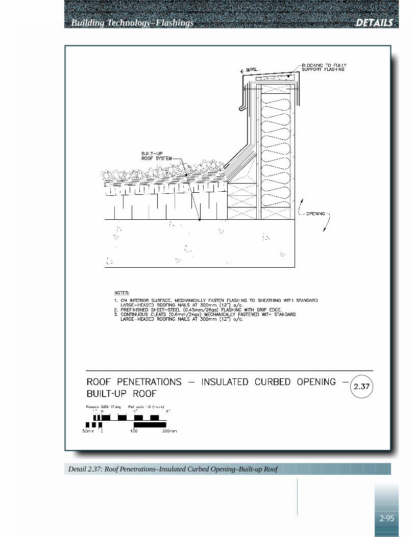
Building Technology–Flashings
2-95
DETAILS
Detail 2.37: Roof Penetrations–Insulated Curbed Opening–Built-up Roof

DETAILS Building Technology–Flashings
2-96
Detail 2.38–RoofPenetrations–Insulated PipeEnclosure–Built-up Roof
PurposeTo maintain a waterproof roof assembly and prevent water leakage aroundpenetrations.
How It Works
• This detail is recommended for penetrations by one or several pipes.• It is good practice to group pipes together to reduce the number of roof
penetrations.• Place the joint between the pipe and the curb on the vertical side to limit
water penetration.• The clearance between the pipe and the curb openings may vary according
to the temperature of the material inside the pipe. The flashing installationaround the curb is similar to that of a low parapet.
• The roofing membrane is turned up the cant, where it is lapped by aseparate base flashing membrane, which extends up to the top of the curband is fastened to the wood blocking.
• This base flashing constitutes the primary waterproofing around the curb.It may be built up of several plies of the same material as that of theroofing membrane, or it may consist of a different but compatible material.
• The cant is used to ease the membrane into the change in direction. It isrequired for built-up roofing membranes and recommended for other typesof roofing membranes.
• The membrane base flashing is covered by a metal counter flashing alongthe perimeter of the curb to protect it from damage and UV radiation. It islapped by a metal cap flashing. Both counter and cap flashings have tightfitting cut-outs at the pipe locations. In addition, the joint between themetal flashing and the perimeter of the pipes is sealed to prevent waterpenetration.
Designer Checklist
❑ A metal sleeve or liner on the inside of the curb opening is specified toprotect combustible materials, if the pipes are hot.
❑ Cap flashing is specified to consist of a continuous piece of metal. ❑ If joints are needed, they are specified to be soldered or otherwise made
watertight such as by folded seams.❑ Adequate provision is made for differential movement between the pipe or
stack and the roof.❑ Roof flashings are designed to allow for easy removal during roof
replacement.
Builder Checklist
❑ Mechanical, plumbing and roofing work are coordinated. The opening androofing around the curb may be completed before the pipe is installed.
❑ If mastic is used to close the opening between the roof slab and hot pipes,ensure that it can withstand the pipe temperature or that the pipes areinsulated.

Building Technology–Flashings
2-97
DETAILS
Detail 2.38: Roof Penetrations–Insulated Pipe Enclosure–Built-up Roof

DETAILS Building Technology–Flashings
2-98
Detail 2.39–RoofPenetrations–Vent Curb–Built-up Roof
PurposeTo maintain a waterproof roof assembly and prevent water leakage at theopening in the roof.
How It Works
• The roofing membrane is terminated on a curb to limit potential waterleakage.
• In the detail shown, the curb does not support any mechanical units but isinstalled to seal around a roof penetration. The curb is built directly on theroof deck and is anchored to it.
• The roofing membrane is turned up the cant, where it is lapped by aseparate strip of base flashing membrane. This membrane extends over thetop of the curb and is fastened on the other side.
• This base flashing constitutes the primary waterproofing along and overthe curb. It may be built up of several plies of the same material as that ofthe roofing membrane, or it may consist of a different but compatiblematerial. If built-up flashing is used, a minimum of two of the pliescontinue to the top of the curb and are fastened on a cant strip.
• The flashing must be adequately supported by the framing of the wall.• The cant is used to ease the membrane into the change in direction. It is
required for built-up roofing membranes and recommended for other typesof roofing membranes.
• The membrane base flashing is covered by metal counter flashing alongthe sides of the curb and lapped by metal cap flashing at the top to protectit from impact damage and UV radiation.
• The metal counter flashing is fastened on the exterior side of the curb,close to the top. The cap flashing is held by a strap or other mechanicalmeans. The joint between the cap flashing and the duct is sealed.
• The sealed joint at the top perimeter of the cap flashing will requirecontinuous maintenance. Where possible, the joint between the duct andthe cap flashing is sheltered by making the duct larger above the curb sothat it overhangs and protects the joint.
Designer Checklist
❑ Indicate locations of curbs and roof slopes. Check drainage to ensure curbsdo not impede the flow of water to drains.
❑ Long metal flashings must be jointed to allow for thermal movements ofthe metal. S-joints in the metal flashing are specified, with no exposedfasteners.

Building Technology–Flashings
2-99
DETAILS
Detail 2.39: Roof Penetrations–Vent Curb–Built-up Roof
DETAILS Building Technology–Flashings
2-100
❑ Select sealants according to the following:• What should be the life expectancy of this joint? • Is the sealant appropriate for the substrate, movement requirements, and
exposure? • Have joint dimensions been specified? • Does the substrate need priming? • Has a bond breaker or backer rod been specified?
❑ Roof flashings are designed to allow for easy removal during roofreplacement.
Builder Checklist
❑ The roof surface is sloped away from the curb, and the curb does notrestrict the flow of water.
❑ The cap flashing is sloped.❑ Flashings are protected from damage during construction.❑ There are no exposed fasteners.❑ Sealant joints
• How will this joint work?• Is the weather and temperature appropriate for applying the sealant
application?• Has the surface been cleaned and primed?• Are the substrate and primer materials compatible?• Is the joint width and depth appropriate for the expected movement?• Is the bond breaker or backer rod of the correct size and properly
positioned?• Has the sealant been tooled to fill the joint without bubbles or other
defects?• Test to ensure that sealant adheres.

Building Technology–Flashings
3-1
Quality
The following are definitions of quality forthe principal parties involved in construction:
• Owner–Quality to an owner means that the construction is fit for theintended purpose and longevity and within the agreed budget.
• Designer–Quality for a designer is conformance to the requirements of theowner, the appropriate building codes and the prevailing state of the art.
• Contractor–Quality for a contractor is strict adherence of construction toplans and specifications.
• Inspector–Quality for an inspector is judging as accurately as possible theadherence of the contractor to the standards established in the plans andspecifications.
• Facilities management–Quality for facilities management personnel isacceptable and predictable building performance.
Responsibilities
The road to quality starts with the owner.The owner should provide the designer with the following expectations:• intended purpose of the building• expectations regarding the life span of building components• maintenance levels acceptable to the owner• construction cost budget consistent with the above expectations
The responsibility for providing this information rests with the owner.
The designer then defines, through drawings and specifications, the intendedquality of the finished building needed to meet owner expectations. Thedesigner should ensure that drawings and specifications are in accordancewith the requirements of the following:
• building codes• current best practice• the agreed-to budget• the owner’s expectations
The drawings convey quantity and specifications convey to the contractor thequality of the product that the owner expects. The responsibility for thequality of this information rests with the designer.
The responsibility for constructing the building in accordance with the plansand specifications rests with the contractor. The contractor should havesystems in place to accomplish the following:• enforce work compliance with drawings and specifications• report changes and seek approval of changes from the designer, prior to
carrying out work, when compliance is impossible• coordinate, schedule and define the roles of the tradespeople involved in
the construction
Chapter 3
INSPECTIONAND QUALITY
CONTROL

inspection and quality control Building Technology–Flashings
3-2
Quality Control and QualityAssurance
Quality ControlThe techniques and activities used to ensure that the work fulfils requirementsfor quality constitute quality control. For example, testing materials andinspecting installation are quality control measures.
Quality AssurancePlanned and systematic actions are needed to ensure with adequate confidencethat a product or service will satisfy given requirements for quality. Theseconstitute Quality Assurance.
Quality assurance must begin at the design stages of the project; quality cannotbe obtained after the work is complete. If the completed work is substandard,there are three options; to accept the substandard product, to repair it, or toreplace it. In building construction, once a particular element is built, replacingit is usually not an option. The other two options are usually potentiallydetrimental to the project. It is therefore essential that a system for qualitycontrol be established right at the start of an activity and maintained through tothe end to achieve the desired quality.
Steps for Quality Assurance ofFlashings
1. Design drawings and specifications should clearly show the location,materials and standards of workmanship for each type of flashing.
2. Any special or extraordinary details should be discussed with anexperienced contractor to ensure that the details can be built.
3. Specifications should include a requirement for a mock-up of each differentflashing detail.
4. Before starting construction, a pre-construction meeting should be held toreview the following:• flashing details• flashing material• construction sequencing and coordination of trades• timing of inspections• contractor’s methods of quality control• construction of mock-up• samples of flashing materials
5. The review of any mock-ups should include testing for drainage andadhesion. At this time, a standard of minimum acceptable quality for thiswork should be established. The accepted mock-ups should be retained forreference.
6. The contractor’s inspector should review the work every day and ensure thatthe standard of quality agreed to for the mock-up is maintained. The owner’sinspector is expected to visit the site periodically to review the constructionof selected flashings. Any deficiencies observed should be pointed out inwriting to the contractor and the owner. The contractor’s inspector mustensure that the deficiencies pointed out by the owner’s inspector arecorrected. The owner’s inspector should then review the previouslydiscovered deficiencies for evidence that they have been corrected.

Building Technology–Flashings
3-3
Flashings: Site InspectionChecklist
The following is a general checklist; specific designer and builder checklistsare provided with each detail.
inspection and quality control
Table 3.1: Site Inspection Checklist
Type Drainage Adhesion Durability Continuity
Base flashings • Sloped to drain • Roofing membrane • Flashing materials • Corners built as detailedlapped as per drawings as specified in accordance with
• Upturn as per drawings • Corrosion-resistant manufacturer’s• Properly fasten to fasteners as instructions
vertical surface as per specified • Terminations asdrawings and • Fastener embedment detailedmanufacturer’s as specified • Penetrations sealedinstructions • Dissimilar metals
• Adequate bond between not in contactflashing and roofing • Joints accommodateplies thermal movements
• Correct priming and • Fasteners bonding agents used accommodate
• Type and embedment thermal movementsof fasteners as specified • Flashing fully
• Edges terminated as supported wheredesigned, specified and requiredrecommended by manufacturer
Counter • Sloped to drain • Fastened to back-up • Flashing material • Penetrations sealedflashings • Drip edges formed material to as specified for as detailed
prevent wind uplift thickness, • Corner joints mitred,as per drawings galvanizing and folded and sealedand specifications finishing as specified
• Fastened to allow • Corrosion-resistantthermal movement fasteners as specified
• Type and embedment • Fastener embedmentof fasteners as as specifiedas specified • Dissimilar metals
have separation• S-lock joints used
to accommodatethermal movements
• Cleats provided asspecified
• Corner joints mitred,folded and sealed asspecified
• Flashing fullysupported whererequired
• UV protection

inspection and quality control Building Technology–Flashings
3-4
Table 3.1: Site Inspection Checklist (continued)
Type Drainage Adhesion Durability Continuity
Valley • Joints lapped in • Fastened to substrate • Flashing materials • End terminationsflashings directions of as specified as specified properly lapped with
flow as detailed • Type and embedment for thickness, roofing as specifiedof fasteners galvanizing • Joints lapped inas specified and finishing direction of flow
• Corrosion-resistant as specifiedfasteners as • Underlay used wherespecified specified
• Fastener embedment • Penetrations sealedas specified
• Dissimilar metalsnot in contact
Wall • Sloped to drain • Lapped materials • Flashing material • Joints lappedflashings • Drain or compatible as specified for • Corners adequately
weepholes present • Priming and thickness, lapped• Joints lapped adhesives applied galvanizing and • Penetrations sealed• End dams where correctly finishing • Laps in flashing
detailed • Types of fasteners • Corrosion-resistant staggered with laps• Drip edge present and embedment fasteners as specified in coping stone• Sheathing paper as specified • Fastener embedment
overlaps flashing • Coping stones as specifiedin wood anchored using • Dissimilar metalsconstruction stainless steel not in contact
• Air barrier dowels • Joints accommodateoverlaps flashing thermal movementin cavity walls as specified

Chapter 4
SAMPLESPECIFICATIONS
4-1
PREAMBLE
Specifications are the legal complement of plans and details. They should notduplicate the information on the drawings but guide the builder in developingthe acceptable choice and application procedures for various materials.Designers must determine for themselves which documents carry informationrelating to material characteristics. Designers must ensure that the relevantinformation concerning application procedures is obtained frommanufacturers and included in the specifications. The building specificationsshould include the following sections:
04150 Masonry Accessories07620 Metal Flashings07900 Sealants
The following specifications are samples, specifying materials andprocedures consistent with the details in Chapter 2. These are not masterspecifications. Designers should explore the use of other methods andmaterials conforming to the relevant CSA standards.
Building Technology–Flashings

SAMPLE SPECIFICATIONS Building Technology–Flashings
4-2
CMHC Best Practice Guide MASONRY ACCESSORIES Section 04150Flashings August 21, 1997
Page 1 of 2
PART 1–GENERAL
1.1 Related Work .1 Masonry Procedures Section 04050.2 Masonry Reinforcing and Section 04160
Connectors
1.2 References .1 CSA A371-94, “Masonry Construction forBuildings.”
PART 2–PRODUCTS
2.1 Materials .1 Masonry flashings:
.1 Self-adhering rubberized asphalt bondedto high-density, cross-laminatedpolyethylene, nominal total thickness of1 mm (0.039 in.).
OR
.2 SBS modified bitumen reinforced withproprietary glass scrim, nominal totalthickness of [ ].
.3 Galvanized steel 0.33 mm (0.013 in.)(minimum) core nominal thickness,Z275 zinc-coating designation, toASTM A525M-80, prefinished toCGSB 93-GP-3M, Class FIS.
.4 Adhesive: recommended by manufacturerof flashing material.
.5 Primer: recommended by manufacturer ofself-adhering flashing.
.6 Plastic cement for bedding metalflashings shall conform to CGSB 37-GP-5M.
.2 Mortar-dropping control device: polyethylenenet 90% open weave, 250 mm (8 in.) high or [ ] or [ ].
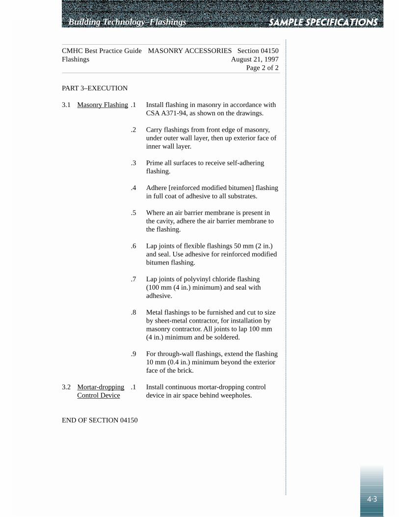
Building Technology–Flashings
4-3
SAMPLE SPECIFICATIONS
CMHC Best Practice Guide MASONRY ACCESSORIES Section 04150Flashings August 21, 1997
Page 2 of 2
PART 3–EXECUTION
3.1 Masonry Flashing .1 Install flashing in masonry in accordance withCSA A371-94, as shown on the drawings.
.2 Carry flashings from front edge of masonry,under outer wall layer, then up exterior face ofinner wall layer.
.3 Prime all surfaces to receive self-adheringflashing.
.4 Adhere [reinforced modified bitumen] flashingin full coat of adhesive to all substrates.
.5 Where an air barrier membrane is present inthe cavity, adhere the air barrier membrane tothe flashing.
.6 Lap joints of flexible flashings 50 mm (2 in.)and seal. Use adhesive for reinforced modifiedbitumen flashing.
.7 Lap joints of polyvinyl chloride flashing(100 mm (4 in.) minimum) and seal withadhesive.
.8 Metal flashings to be furnished and cut to sizeby sheet-metal contractor, for installation bymasonry contractor. All joints to lap 100 mm(4 in.) minimum and be soldered.
.9 For through-wall flashings, extend the flashing10 mm (0.4 in.) minimum beyond the exteriorface of the brick.
3.2 Mortar-dropping .1 Install continuous mortar-dropping control Control Device device in air space behind weepholes.
END OF SECTION 04150

SAMPLE SPECIFICATIONS Building Technology–Flashings
4-4
CMHC Best Practice Guide METAL FLASHINGS Section 07620Flashings August 26, 1997
Page 1 of 4
PART 1–GENERAL
1.1 Related Work .1 Masonry Accessories Section 04150
1.2 Mock-Up .1 Build mock-ups for each type of flashing andcounter flashing complete with all fasteners asper drawings and specifications, and obtainArchitect’s approval prior to fabrication of anyfurther metal flashings.
1.3 Product Delivery, .1 Deliver sheet-metal flashing materials to site Storage and and store in safe, protected storage area toHandling prevent damage.
.2 Stack flashings to prevent twisting or bendingout of shape.
.3 Prevent contact of flashing materials withcorrosive substances.
.4 Damaged materials shall be replaced with newmaterials.
.5 Handle and store metal flashings so thatmarring and scratching of the coatings do notoccur.
1.4 Guarantee .1 Guarantee flashing assembly free of thefollowing defects: splitting seams, lifting,loosening and undue expansion for two yearsfrom date of substantial performance.
PART 2–PRODUCTS
2.1 Materials .1 Metal Flashings
Galvanized steel, 0.45 mm (26 ga.) (0.018 in.)core nominal thickness, Z275 zinc-coatingdesignation, to ASTM A525M-80, prefinishedto CGSB 93-GP-3M, Class FIS.
Colour to Architect’s later choice frommanufacturer’s standard range.

Building Technology–Flashings
4-5
SAMPLE SPECIFICATIONS
CMHC Best Practice Guide METAL FLASHINGS Section 07620Flashings August 26, 1997
Page 2 of 4
.2 Cleats and Fasteners
Cleats and fasteners shall be of the samematerial as the metal they are designed tosecure. Size shall be to suit components to besecured. Gauge shall be sufficient to retain theflashings in place.
.3 Nails
Hot-dipped galvanized steel, spiral thread, ofsufficient length to provide a minimum 25 mm(1 in.) penetration into substrate.
.4 Plastic Cement
Plastic cement for caulking and beddingflashings shall conform to CGSB 37-GP-5M.
.5 Sealant
Refer to section 07900.
.6 Bituminous Paint
Bituminous paint shall conform to CGSB 1-GP-108, Type II.
PART 3–EXECUTION
3.1 Workmanship .1 Metal flashing shall be as detailed,supplemented by recommendations ofCanadian Roofing Contractors’AssociationSpecifications.
.2 All free edges of metal flashing shall bestrengthened by a fold at least 13 mm (0.5 in.)wide, set out slightly and presenting a straightline and a neat finish.
.3 Form flashings in 2400 mm (8 ft.) lengthswhenever possible. Make allowance forexpansion at joints.

SAMPLE SPECIFICATIONS Building Technology–Flashings
4-6
CMHC Best Practice Guide METAL FLASHINGS Section 07620Flashings August 26, 1997
Page 3 of 4
.4 End joints where adjacent lengths of metalflashing meet shall be made using an S-joint.This shall be executed by inserting the end ofone coping length in a 25 mm (1 in.) deep S-joint formed in the end of the adjacent lengthin a full bed of caulking compound. Concealedportion of the S-joint shall extend 25 mm(1 in.) outwards and be nailed to the substrate.Face nailing of the joints will not be permitted.
.5 The metal shall be formed on a bending brake.Shaping, trimming and hand-seaming shall bedone on the bench as far as is practicable withthe proper sheet-metal working tools. Theangle of the bends and the folds forinterlocking the metal shall be made with fullregard to expansion and contraction to avoidbuckling or fullness in the metal after it is inservice and to avoid damaging the surface ofthe metal.
.6 Install continuous starter strips where indicatedor required to present a true, non-waving,leading edge. Anchor to back-up to providerigid, secure installation.
.7 Apply isolation coating to aluminum surfacesto be in contact with concrete or mortar.
.8 Corner joints where adjacent lengths of metalflashing meet shall be made using foldedjoints. Apply a continuous bead of sealant as anadditional protection.
3.2 Counter .1 Install counter flashings as soon as possible Flashings after membrane flashings are in place.
.2 Counter flashings shall have a folded, bottom-edge, stiffening break, where indicated, andshall extend up the vertical face of the wall orcurb to height shown, then be turned intoreglets or interlocked with cap flashings.
.3 Wedge flashings into reglets and caulk neatlyusing specified sealant and bond breaker.

Building Technology–Flashings
4-7
SAMPLE SPECIFICATIONS
CMHC Best Practice Guide METAL FLASHINGS Section 07620Flashings August 26, 1997
Page 4 of 4
3.3 Cap Flashings .1 Tops of walls, parapets, counter flashings andthe like shall be cap flashed as detailed, aftermembrane and metal counter flashings are inplace.
END OF SECTION 07620

SAMPLE SPECIFICATIONS Building Technology–Flashings
4-8
CMHC Best Practice Guide SEALANTS Section 07900Flashings August 26, 1997
Page 1 of 5
PART 1–GENERAL
1.1 Guarantee .1 Provide a written guarantee, signed and issuedin the name of the owner, stating that caulkingwork of this section is guaranteed againstleakage, cracking, crumbling, melting,shrinkage, running, loss of adhesion, stainingadjacent surfaces, or other failure, for a periodof three years from the date of Certificate ofSubstantial Performance.
1.2 Delivery, .1 Deliver and store materials in original Storage and wrappings and containers with manufacturer’sHandling seals and labels intact. Protect from freezing,
moisture and water.
1.3 Environmental .1 Comply with requirements of Workplace and Safety Hazardous Materials Information SystemRequirements System (WHMIS) regarding use, handling,
storage and disposal of hazardous materials;and regarding labelling and provision ofmaterial safety data sheets acceptable toHuman Resources Development Canada.
.2 Conform to manufacturer’s recommendedtemperatures, relative humidity and substratemoisture content for application and curing ofsealants, including special conditionsgoverning use.
.3 Architect will arrange for ventilation system tobe operated on maximum outdoor air andexhaust during installation of caulking andsealants.] [Ventilate work area as directed byarchitect, using approved portable supply andexhaust fans.]

Building Technology–Flashings
4-9
SAMPLE SPECIFICATIONS
CMHC Best Practice Guide SEALANTS Section 07900Flashings August 26, 1997
Page 2 of 5
PART 2–PRODUCTS
2.1 Sealant .1 Sealants shall conform to CGSB specifications Materials as listed below; colour to architect’s selection.
.1 Type 1: Multi-component, epoxidizedpolyurethane terpolymer sealant. To meetspecified requirements of CGSBSpecification CAN2.19-24-M90. Use atall locations including sealant beadsbelow foundation flashing and flashing atshelf angles, except where another type isspecified.
.2 Type 2: One part elastomeric sealants: tomeet specified requirements ofNSC/CGSB Specification CAN2-19.13-M87.
.1 Classification MC-2-25-B-Nmoisture curing hybridpolyurethane. Use at curtain walljoints; perimeter caulking ofwindows, doors and panels; beddingfor mullions, panels and frames.
.2 Classification MCG-2-25-A-Lmedium modulus silicone, to beused in glass-to-glass, glass-to-metaland metal- to-metal joints.
2.2 Back-up .1 Polyolefin polyethylene, urethane, neoprene or Materials vinyl foam
.1 Extruded closed cell backer rod.
.2 Size: oversize 30–50%.
.3 Chemically compatible with primers andsealants.
.4 Round solid rod, Shore A hardness 70.
.2 Bond breaker tape
.1 Polyethylene bond breaker tape that willnot bond to sealant.
2.3 Joint Cleaner .1 Non-corrosive and non-staining type,compatible with joint-forming materials andsealant recommended by sealant manufacturer.
2.4 Primer .1 Primer: as recommended by manufacturer.

SAMPLE SPECIFICATIONS Building Technology–Flashings
4-10
CMHC Best Practice Guide SEALANTS Section 07900Flashings August 26, 1997
Page 3 of 5
PART 3–EXECUTION
3.1 Extent of Work .1 Install sealants in all locations shown ondrawings.
.2 Install sealant at the perimeter of all exterioropenings where doors, windows, grilles andother items abut or penetrate the exterior wallmaterials.
.3 At all door saddles, spread a bead of sealantcompound over entire seat of saddles at least3 mm (0.12 in.) thick before installing saddle.
.4 Seal the junctions of differing exterior wallmaterials.
.5 Provide a minimum of two continuous beads ofsealant under all prefinished galvanized steelwall flashings.
3.2 Preparation of .1 Examine joints sizes and conditions to Joint Surfaces establish correct depth- to-width relationship
for installation of backup materials andsealants. Maintain depth of sealant at middle ofjoint width as follows:
Joint Width Sealant Width
6 mm (0.25 in.) 6 mm (0.25 in.)
20 mm (0.75 in.) 10 mm (0.4 in.)
32 mm (1.25 in.) 13 mm maximum (0.5 in.)
Minimum adhesion surface shall be 1.5 timesdepth.
.2 Clean bonding joint surfaces of harmfulsubstances including dust, rust, oil, grease andother matter that may impair work.
.3 Do not apply sealants to joint surfaces treatedwith sealer, curing compound, water repellentor other coatings, unless tests have beenperformed to ensure compatibility of materials.Remove coatings as required.
.4 Ensure joint surfaces are dry and frost-free.

Building Technology–Flashings
4-11
SAMPLE SPECIFICATIONS
CMHC Best Practice Guide SEALANTS Section 07900Flashings August 26, 1997
Page 4 of 5
.5 Prepare surfaces in accordance withmanufacturer’s directions.
3.3 Priming .1 Where necessary to prevent staining, maskadjacent surfaces prior to priming and sealing.
.2 Prime sides of joints in accordance with sealantmanufacturer’s instructions, immediately priorto sealing.
3.4 Backup Material .1 Apply bond breaker tape where required tomanufacturer’s instructions.
.2 Install joint filler to achieve correct joint depthand shape.
3.5 Mixing .1 Mix materials in strict accordance with sealantmanufacturer’s instructions.
3.6 Application .1 Sealant:
.1 Apply sealant in accordance withmanufacturer’s instructions withintemperature restrictions.
.2 Apply sealant in continuous beads.
.3 Apply sealant using gun with proper-sized nozzle.
.4 Use sufficient pressure to fill voids andjoints solidly.
.5 Form surface of sealant with full bead,smooth, and free from ridges, wrinkles,sags, air pockets and embeddedimpurities.
.6 Tool exposed surfaces to give slightlyconcave shape.
.7 Remove excess compound promptly aswork progresses and upon completion.
.2 Curing:.1 Cure sealants in accordance with sealant
manufacturer’s instructions..2 Do not cover up sealants until proper
curing has taken place.

SAMPLE SPECIFICATIONS Building Technology–Flashings
4-12
CMHC Best Practice Guide SEALANTS Section 07900Flashings August 26, 1997
Page 5 of 5
.3 Cleanup:
.1 Clean adjacent surfaces immediately andleave work neat and clean.
.2 Remove excess and droppings, usingrecommended cleaners as workprogresses.
.3 Remove masking tape after initial set ofsealant.
END OF SECTION 07900

Chapter 5
CAD DETAIL LIBRARY
5-1
Overview
The CMHC Best Practice Guide: FlashingsCAD Detail Library is a collection of drawing files created with AutoCADrelease 12 software. Two types of files are included. The first type of file endswith the .DWG filename extension. The .DWG extension files are inAutoCAD drawing format and are compatible with versions of AutoCADstarting with release 10 or any other CAD/graphics package capable ofimporting AutoCAD release 10 drawings. The second type of file, .DXF, isprovided for universal importation into other CAD/graphics programs that donot support the .DWG format but support .DXF files. Consult your softwaremanual on how to import .DWG or .DXF files into your CAD/graphicsprogram.
The CAD Detail Library does not require any special configurations of yourCAD, graphics or computer operating system. The detail drawings require nomore memory or disk space than if you had created them yourself.
The details are designed to be usable without modification. Each librarydetail has been prepared to allow simple insertion onto a drawing sheet. Youmay explode and modify the details as required and use their components asblocks in the same way you would use a block you created yourself. You maywish to save your modified versions as new, separate drawing files for futureuse.
Assumption
It is assumed that the user has a basicknowledge of his or her CAD/graphics software, and therefore no attempt hasbeen made to explain layering, fonts, colours and other basic drawingconventions of these programs.
Disclaimer
The drawings and texts are intended as ageneral practice guide only. CMHC does not warrant, nor assume liabilityfor, the accuracy or completeness of the drawings or texts, or their fitness forany particular use. It is the responsibility of users to apply their professionalknowledge in the use of information contained in these drawings,specifications and tests, to consult original sources, or when appropriate, toconsult an architect or engineer.
Project- and site-specific factors of climate, exposure, cost, aesthetics and soon must be taken into consideration in the design of an appropriate buildingenvelope.
What’s on the Disk
The details and text in the guide are alsoincluded on the CD-ROM. A README.TXT file is included that containsinformation on layering, pen weight/colour assignments and other drawinginformation.
Building Technology–Flashings

REFERENCES
R-1
Beznaczuk, L. M., and M. A. Lacasse. Construction Practice: PrototypeSealant Selection Systems. Ottawa, ON: Institute for Research inConstruction, National Research Council.
Canadian Roofing Contractors Association. Roofing Specifications Manual(Revised). November 1990. Ottawa, ON: CRCA.
Drysdale, R. G. Construction Problems in Multifamily Residential Buildings.Ottawa, ON: CMHC, 1991.
Drysdale, R. G., and Suter, G. T. Exterior Wall Construction in High-RiseBuildings. Ottawa, ON: CMHC, 1991.
Forgues, I. E. Construction Practice: Properly Sealed Construction Joints.Ottawa, ON: Institute for Research in Construction, National ResearchCouncil.
Margeson, J. L. Construction Practice: How to Increase the Life of YourSealant. Ottawa, ON: Institute for Research in Construction, NationalResearch Council.
Ontario Code and Construction Guide for Housing (2nd ed.). Don Mills,ON: Ontario Ministry of Housing and New Home Warranty Program, June1993.
Patenaude, A. Migration of Water By Capillarity. Ottawa, ON: CMHC, 1993.
Skylight detail: Guide technique visant la conception, l’installation etl’utilisation des lanterneaux aux fenêtres inclinées. Unpublished 1997research report by Association provinciale des constructeurs d’habitation duQuebec.
Building Technology–Flashings


appendix A
A-1
Files on CD-ROM
Drawing FilesThe details included in this guide are also included in the CD-ROM asAutoCAD© release 12 DWG files, and as DXF files. All are provided in SI(Metric) versions at 1:5 scale and are plotted at 1:1 plotting scale, with layersoffering a choice of English or French notes and titles. Refer toREADME.TXT on CD-Rom for further information.
This CD contains the following directories and their sub-directories:
• DWG (A directory containing drawings of details in AutoCAD• DXF (A directory containing drawings of details in DXF format• PDF (Complete set of the documentation in PDF format)• SPEC (Complete specification in txt file format)
About 6 megabytes of free space is required for the DWG files and 16.5megabytes for the DXF files.
In addition to the above directories, the CD contains the following files:
AR16E301.EXE : Installs Acrobat Reader for Windows 3.1xAR32E301.EXE : Installs Acrobat Reader for Windows 95LIC_RDR.PDF : A licence agreement for the Acrobat ReaderREADME.TXT : The README fileLISEZMOI.TXT : Same as the README file but in French
To install the Acrobat Reader on Windows 3.1x:
1. From Program Manager, Select File then Run2. Browse and Select AR16E301.EXE3. Click on OKFollow the instructions on the screen.
To install the Acrobat Reader on Windows 95:1. From START menu, Select Run2. Browse and Select AR32E301.EXE3. Click on OKFollow the instructions in the screen.
Specification FilesThe guide specifications, sections 04150, 07620 and 07900, are included inthe CD-ROM in WP5 format conforming to the CSC Electronic Style Guide,which should be capable of being used with almost any PC-compatible wordprocessor. It is provided in both English and French, in SI (Metric) units,CSC Page Format, and refers to applicable Canadian standards. Refer toREADME.TXT on CD-Rom for further information.
Building Technology–Flashings


Other useful information products from Canada Mortgage and Housing Corporation.
Innovation Centre for Highrise and MultiplesStay up-to-date with the latest research through the Innovation Centre for Highrise and Multiples Web site,reachable through the main CMHC Web site at www.cmhc-schl.gc.ca
Best Practices Guide: Brick Veneer Steel StudImprove building envelope performance with this easy to-follow guide. Includes a CD-ROM with CAD drawingsand specification tables in metric and imperial measurements. Order # 6915E
Best Practices Guide: Brick Veneer Concrete MasonryDiscover the benefits of various components and materials used in brick veneer/concrete masonry unit backingand important considerations in their applications. Includes a CD-ROM with details, and checklists to help withconstruction sequencing, inspection and quality control. Order # 6917E
Place your order now by calling
1 800 668-2642Outside Canada phone 613 748-2003