bend bright
TRANSCRIPT
8/2/2019 Bend Bright
http://slidepdf.com/reader/full/bend-bright 1/11
Draka Comteq | Optical Fibre
BendBrightXS Single Mode Optical Fibre
Features Benefits
• Low macrobending loss in the 7 to 15 mm bend radius • Allows shorter radius storage of fibre over-length leading to more
range compact installations
• Is more forgiving for installation errors in fibre managements systems
and/or splice protection devices
• Compatibility with other G.652 single mode fibre • The BendBright XS can be spliced with similar settings of the fusion
installations splice programs as applied for other G.652 fibre
• Low loss splicing of BendBrightXS
to other G.652 fibres can be done
with standard fusion splicers
• Low bending loss at partial bends in the mm bend radius • Allows for tight in-building installations
range • Allows for small volume patch panel installations
• Prevents fibre coating degradation in case high power pump systems are
used in up-grading scenarios
• Low micro-bending loss • Allows for highly demanding cable designs including ribbons
Key Industry Leading Milestones
2002 BendBright G.652B introduced; industry leading bend-insensitive single mode fibre
2005 BendBright G.652D introduced; allowing use of both E-band and L-band for low bend radius telecom applications
2006 AT&T awarded Draka Comteq with award for Technical Innovations for drop cable containing BendBright fibre
2006 BendBrightXS introduced; the first commercial fibre fully compliant with G.652D and G.657A&B
Draka Comteq | Optical Fibre
Netherlands: France: USA:
Tel: +31 (0)40 29 58 700 Tel: +33 (0)3 21 79 49 00 Tel: +1 828 459 8446
Fax: +31 (0)40 29 58 710 Fax: +33 (0)3 21 79 49 33 Fax: +1 828 459 8267
Email: [email protected] Website: www.drakafibre.com | www.draka.com
Issue date: 11/07
Supersedes: 03/07
Enhanced low macrobending sensitive, low water peak fibre
Product Type: G.652D, G.657A&B
Coating Type: ColorLock™ and Natural
Draka Comteq BendBright XS fibre combines two attractive features: excellent low macro-bending sensitivity and
low water-peak level. Together they allow unlimited use of the whole telecom wavelength window for a great
variety of applications. This next generation behavior has been obtained by adding a trench with a lowered
refractive index in the cladding area preventing the optical field to escape. This has been designed in such a way
that no compromise has been made with respect to the main tranismission parameters.
Apart form its use in office installations, as patch cords and/or interconnection cables, the use of the BendBright xs
in Fiber-to-the-Home networks offers significant added value to the network installers. Bend radii in fibre quidance
ports can be reduced as well as minimum bend radii in wall and corner mountings. As the fibre is very forgiving
for installation errors, reduced demands for the skills of the installation engineers may further reduce the costs.Its enhanced macrobending behaviour further guarantee that the 1625 nm window (L-band) will be available for
future use in this bandwith hungry environment.
Draka Comteq’s Advanced Plasma and Vapor Deposition (PCVD and APVD™) manufacturing process ensures
the highest quality and purity of fibres. Proprietary ColorLock™ coating process further enhances the
performance, durability and reliability of the fibre, even in the harshest environments.
The fibre fully complies with or exceeds the ITU-T Recommendation G.652.D, G.657A&B and the IEC 60793-2-50
type B.1.3 Optical Fibre Specification and is backwards compatible with all other G.652 fibre used in current optical
networks.
SA 07/1451
8/2/2019 Bend Bright
http://slidepdf.com/reader/full/bend-bright 2/11
Optical Specifications (Uncabled fibre)Attenuation Max. Value (dB/km)
Attenuation at 1310 nm 0.33 – 0.35Attenuation at 1383 nm H2 aged* 0.32 – 0.35Attenuation at 1460 nm 0.25Attenuation at 1550 nm 0.19 – 0.20Attenuation at 1625 nm 0.20 – 0.21* Hydrogen aging per IEC 60793-2-50, type B.1.3
Other values available on request.
Attenuation vs. Wavelength
Maximum attenuation change over the window from reference
Wavelength range (nm) Reference λ (nm) Change (dB/km)
1285 - 1330 1310 ≤ 0.031525 - 1575 1550 ≤ 0.021460 - 1625 1550 ≤ 0.04
Attenuation UniformityNo point discontinuity greater than 0.05 dB at 1310 nm and 1550 nm.
Attenuation with BendingNumber of Mandrel Wavelength InducedTurns Radius (nm) attenuation
(mm) (dB)
10 15 1550 ≤ 0.0310 15 1625 ≤ 0.11 10 1550 ≤ 0.11 10 1625 ≤ 0.21 7.5 1550 ≤ 0.51 7.5 1625 ≤ 1.0
Cutoff WavelengthCable Cutoff wavelength ≤ 1260 nm
Mode Field Diameter Wavelength (nm) MFD (µm)
1310 8.5 – 9.3
1550 9.4 – 10.4
Chromatic DispersionZero Dispersion Wavelength (λ0): 1300 - 1324 nmSlope (S0) at λ0: ≤ 0.092 ps/(nm2.km)
Polarization Mode Dispersion (PMD)(ps/√km)
PMD Link Design Value** ≤ 0.06Max. Individual Fibre ≤ 0.1** According to IEC 60794 -3, Ed 3 (Q=0.01%)
Geometrical SpecificationsGlass Geometry
Cladding Diameter 125.0 ± 0.7 µmCore/Cladding Concentricity ≤ 0.5 µmCladding Non-Circularity ≤ 0.7 %Fibre Curl (radius) ≥ 4 m
Coating Geometry
Coating Diameter 242 ± 7 µmCoating / Cladding Concentricity ≤ 10 µmCoating Non-Circularity ≤ 5 %
Lengths Standards lengths up to 25.2 kmOther lengths available on request.
Mechanical SpecificationsProof test
The entire length is subjected to a tensile proof stress > 0.7 GPa(100 kpsi); 1% strain equivalent.
Tensile Strength
Dynamic tensile strength (0.5 meter gauge length):Aged*** and unaged: median > 3.8 GPa (550 kpsi)*** Aging at 85°C, 85% RH, 30 days
Dynamic and Static Fatigue
Dynamic fatigue, unaged and aged*** nd > 20Static fatigue, aged*** n
s> 23
Coating Performance
Coating strip force unaged and aged****:- Average strip force: 1 N to 3 N- Peak strip force: 1.3 N to 8.9 N**** Aging:
• 23°C, 0°C and 45°C• 30 days at 85°C and 85% RH• 14 days water immersion at 23°C• Wasp spray exposure (Telcordia)
Environmental SpecificationsEnvironmental Test Test Conditions Induced Attenuation at
1310, 1550 nm (dB/km)
Temperature cycling –60°C to 85°C ≤ 0.05
Temperature- –10°C to 85°C, 4-98% RH ≤ 0.05Humidity cycling
Water Immersion 23°C, 14 days ≤ 0.05Dry Heat 85°C, 30 days ≤ 0.05Damp Heat 85°C; 85% RH, 30 days ≤ 0.05
Typical Characterisation ValuesNominal Zero Dispersion Slope 0.087 ps/(nm2.km)
Effective group index @ 1310 nm 1.467Effective group index @ 1550 nm 1.467Effective group index @ 1625 nm 1.468
Rayleigh Backscatter Coefficient for 1 ns pulse width:@ 1310 nm –79.1 dB
@ 1550 nm –81.4 dB@ 1625 nm -82.2 dB
Median Dynamic Tensile Strength 5.3 GPa (750 kpsi)(Aged at 85ºC, 85% RH, 30 days; 0,5 m gauge length)
Draka Comteq | Optical Fibre
BendBrightXS Single Mode Optical Fibre
Issue date: 11/07Supersedes: 03/07
The Draka Comteq Optical Fibre policy of continuous improvement may cause in changed specifications without prior notice.
Enhanced low macrobending sensitive, low water peak fibre
Product Type: G.652D, G.657A&BCoating Type: ColorLock™ and Natural

8/2/2019 Bend Bright
http://slidepdf.com/reader/full/bend-bright 3/11
Draka Comteq | Optical Fibre
BendBright XS : Macrobending improved single mode fibre
Issue date: 10/07
Supersedes: 08/06
Application Note
For telecom networks bend loss has hardly been an
issue for many years. Bending the fibre into a helical
path is needed to create fibre over-length allowing
cable elongation during installation and a suitable
temperature operating window. This requirement was
met quite easily. Bend radii well over 100 mm did not
put high demands on the fibre bend loss. A further
requirement was in the need to have storage of the
fibre over-length in the splice enclosures along a route.
The well-known “100 turns” requirement was created
to represent the total number of fibre storage loops in
a route. Radii of interest decreased to 30 mm, but for
a limited length only. A more severe tightening
occurred from the increase of operational wavelength
into the long wavelength 1625 nm band. The asso-
ciated extending optical field width at higher wave-
lengths makes the fibre more sensitive to bending. This
ended up in the ITU-T Recommendations and IEC
standards with the current requirement of a maximum
added loss of 0.1 dB at 1625 nm for 100 turns with a
30 mm radius.
First generation bend performance improvements were
addressed by standard single mode fibre (SMF) with its
simple step-index profile of the core. The only
measures taken by the fibre manufacturers were the
gradual decrease of the nominal mode-field diameter
(MFD) at 1310 nm down to about 9 µm and an increase
of the average cable cut-off wavelength to a value
not far below the lower limit of the operating wave-
length window. These transitions were supported by
narrowing production tolerances allowing prevention of
worst case fibres.
The minimum bend radius of 30 mm has had a big
impact. In most fibre management systems this mini-
mum radius can be recognized in storage cassettes as
well as in entrance and exit guides. More or less, the
30 mm radius has been considered as being a “natural
law” which should not be violated. However, this situa-
tion has come to an end.
Application note: BendBright XS Draka Comteq | Optical Fibre 1
0. Introduction
The BendBright series of macrobending improved single mode fibres (SMF) for telecom networks answers the
market demand for bend-optimized SMF. Especially the BendBright XS shows perfect performance for the strin-
gent needs in modern Fibre-to-the Home (FttH) networks or in more general access networks (XS=access). The
aim of this Application Note is to support the user in the various applications of BendBright XS in telecom cables
and networks, especially as they apply to the mixed use with conventional SMF. This Note starts with an overview
section on the growing impact of macrobending loss throughout the years and the importance of backwards com-
patibility with the SMF applied in the “installed base” networks. Sections 3, 4 and 5 describe the particular issues
related to macrobending, microbending and fibre connection, respectively. The final section covers lifetime
aspects and some miscellaneous subjects. Specific fibre data and detailed specifications can be found in the
product datasheet .
nailed
indoor
cable
cable
towards 1625 nm
fibrecassettes
1. Macrobending loss: growing impact
SA 07/1452
8/2/2019 Bend Bright
http://slidepdf.com/reader/full/bend-bright 4/11
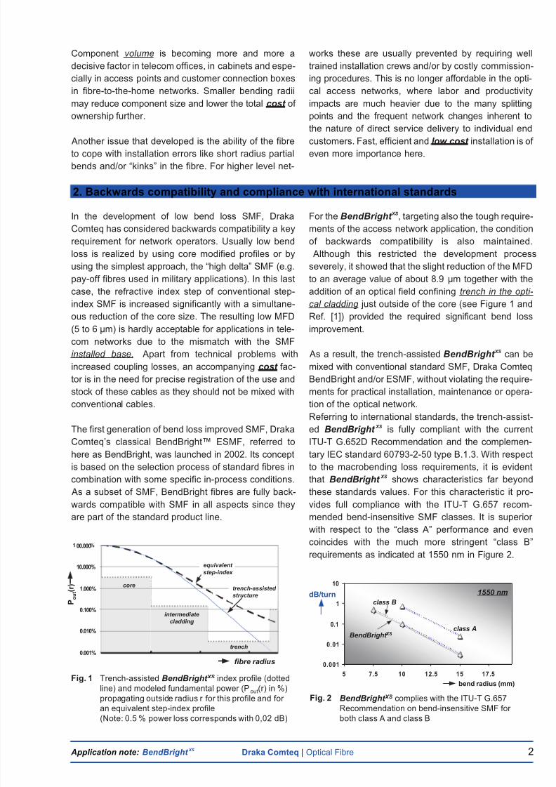
Fig. 1 Trench-assisted BendBright XS index profile (dotted
line) and modeled fundamental power (Pout(r) in %)propagating outside radius r for this profile and for
an equivalent step-index profile
(Note: 0.5 % power loss corresponds with 0,02 dB)
0.001%
0.010%
0.100%
1.000%
10.000%
00.000
equivalent
step-index
trench-assisted
structure
core
intermediate
cladding
trench
fibre radius
P o u t
( r )
Application note: BendBright XS Draka Comteq | Optical Fibre 2
Component volume is becoming more and more a
decisive factor in telecom offices, in cabinets and espe-
cially in access points and customer connection boxes
in fibre-to-the-home networks. Smaller bending radii
may reduce component size and lower the total cost of
ownership further.
Another issue that developed is the ability of the fibre
to cope with installation errors like short radius partial
bends and/or “kinks” in the fibre. For higher level net-
works these are usually prevented by requiring well
trained installation crews and/or by costly commission-
ing procedures. This is no longer affordable in the opti-
cal access networks, where labor and productivity
impacts are much heavier due to the many splitting
points and the frequent network changes inherent to
the nature of direct service delivery to individual end
customers. Fast, efficient and low cost installation is of
even more importance here.
In the development of low bend loss SMF, Draka
Comteq has considered backwards compatibility a key
requirement for network operators. Usually low bend
loss is realized by using core modified profiles or by
using the simplest approach, the “high delta” SMF (e.g.
pay-off fibres used in military applications). In this last
case, the refractive index step of conventional step-
index SMF is increased significantly with a simultane-
ous reduction of the core size. The resulting low MFD
(5 to 6 µm) is hardly acceptable for applications in tele-
com networks due to the mismatch with the SMF
installed base. Apart from technical problems with
increased coupling losses, an accompanying cost fac-
tor is in the need for precise registration of the use and
stock of these cables as they should not be mixed with
conventional cables.
The first generation of bend loss improved SMF, Draka
Comteq’s classical BendBright™ ESMF, referred to
here as BendBright, was launched in 2002. Its concept
is based on the selection process of standard fibres in
combination with some specific in-process conditions.
As a subset of SMF, BendBright fibres are fully back-
wards compatible with SMF in all aspects since they
are part of the standard product line.
For the BendBright XS, targeting also the tough require-
ments of the access network application, the condition
of backwards compatibility is also maintained.
Although this restricted the development process
severely, it showed that the slight reduction of the MFD
to an average value of about 8.9 µm together with the
addition of an optical field confining trench in the opti-
cal cladding just outside of the core (see Figure 1 and
Ref. [1]) provided the required significant bend loss
improvement.
As a result, the trench-assisted BendBright XS can be
mixed with conventional standard SMF, Draka Comteq
BendBright and/or ESMF, without violating the require-
ments for practical installation, maintenance or opera-
tion of the optical network.
Referring to international standards, the trench-assist-
ed BendBright XS is fully compliant with the current
ITU-T G.652D Recommendation and the complemen-
tary IEC standard 60793-2-50 type B.1.3. With respect
to the macrobending loss requirements, it is evident
that BendBright XS shows characteristics far beyond
these standards values. For this characteristic it pro-
vides full compliance with the ITU-T G.657 recom-
mended bend-insensitive SMF classes. It is superior
with respect to the “class A” performance and even
coincides with the much more stringent “class B”
requirements as indicated at 1550 nm in Figure 2.
2. Backwards compatibility and compliance with international standards
0.001
0.01
0.1
1
10
5 7.5 10 12.5 15 17.5
class A
class B
bend radius (mm)
dB/turn
Fig. 2 BendBright XS complies with the ITU-T G.657
Recommendation on bend-insensitive SMF for
both class A and class B
1550 nm
BendBright XS
8/2/2019 Bend Bright
http://slidepdf.com/reader/full/bend-bright 5/11
Application note: BendBright XS Draka Comteq | Optical Fibre 3
Low macrobending loss is needed
i) for storage of fibre, cord or cable over-length in
patch-panels or in splicing cassettes and
ii) in case of single low radius bends as occurring
in entrance and exit guides of fibre manage-
ment systems, in indoor cable installations or
due to maltreatment of the fibre (e.g. “stapling”
or “nailing” the indoor cable).
For SMF, a commonly applied specification for bending
loss is in the added loss per turn at a given wavelength.
This loss increases linearly with the number of turns,
so the specified loss for any number of turns can be
calculated quite easily. As SMF bend loss increases
with wavelength, the specification at the highest
envisioned wavelength, i.e. 1625 nm is most critical.
For applications where 1550 nm is considered as
the highest operational wavelength a specification at
this wavelength suffices. For BendBright XS, the loss
at both wavelengths has been specified. The ratio
between the losses at both wavelengths is not constant
but depends on the bending radius. For 15 mm radius
this ratio is about 5 and for 7.5 mm it has decreased
to 2.5.
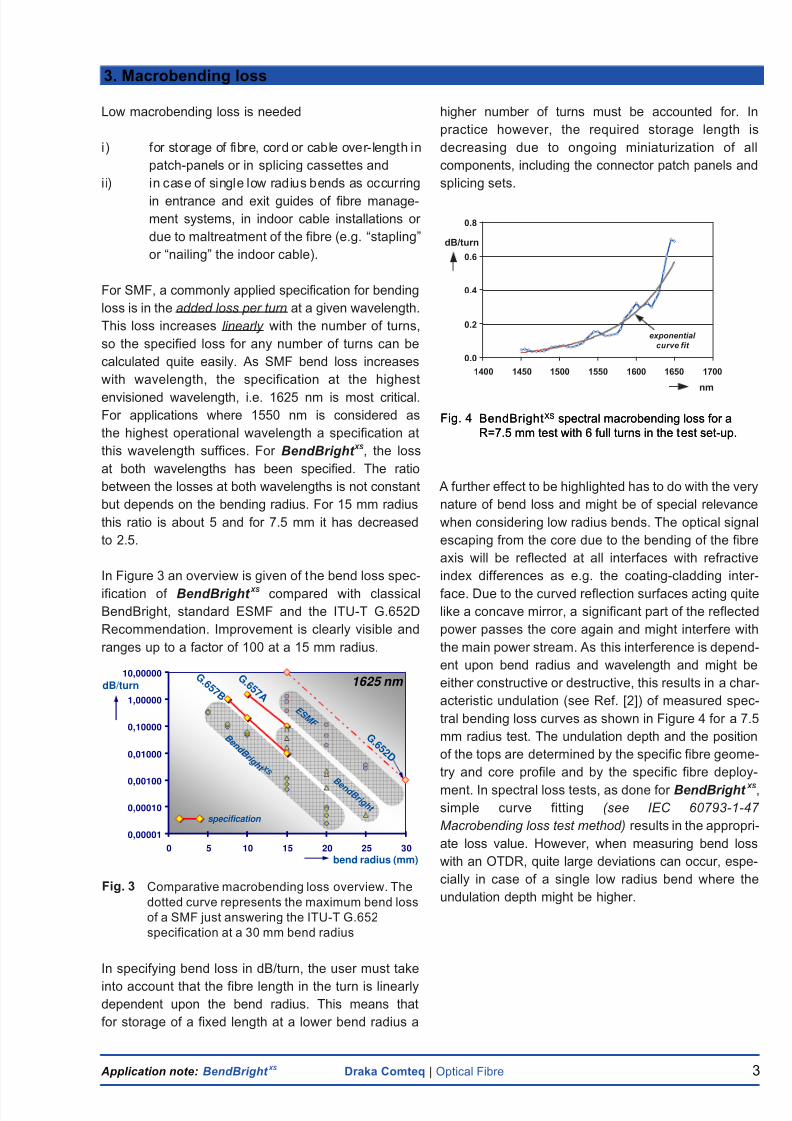
In Figure 3 an overview is given of the bend loss spec-
ification of BendBright XS compared with classical
BendBright, standard ESMF and the ITU-T G.652D
Recommendation. Improvement is clearly visible and
ranges up to a factor of 100 at a 15 mm radius.
In specifying bend loss in dB/turn, the user must take
into account that the fibre length in the turn is linearly
dependent upon the bend radius. This means that
for storage of a fixed length at a lower bend radius a
higher number of turns must be accounted for. In
practice however, the required storage length is
decreasing due to ongoing miniaturization of all
components, including the connector patch panels and
splicing sets.
A further effect to be highlighted has to do with the very
nature of bend loss and might be of special relevance
when considering low radius bends. The optical signal
escaping from the core due to the bending of the fibre
axis will be reflected at all interfaces with refractive
index differences as e.g. the coating-cladding inter-
face. Due to the curved reflection surfaces acting quite
like a concave mirror, a significant part of the reflected
power passes the core again and might interfere with
the main power stream. As this interference is depend-
ent upon bend radius and wavelength and might be
either constructive or destructive, this results in a char-
acteristic undulation (see Ref. [2]) of measured spec-
tral bending loss curves as shown in Figure 4 for a 7.5
mm radius test. The undulation depth and the position
of the tops are determined by the specific fibre geome-
try and core profile and by the specific fibre deploy-
ment. In spectral loss tests, as done for BendBright XS,
simple curve fitting (see IEC 60793-1-47
Macrobending loss test method) results in the appropri-
ate loss value. However, when measuring bend loss
with an OTDR, quite large deviations can occur, espe-
cially in case of a single low radius bend where the
undulation depth might be higher.
3. Macrobending loss
0,00001
0,00010
0,00100
0,01000
0,10000
1,00000
10,00000
0 5 10 15 20 25 30
G . 6 5 2 D
E S M F
B e n d B
r i g h t
B e n d B
r i g h t X S
dB/turn
bend radius (mm)
specification
G . 6 5 7 B
G . 6 5 7 A
1625 nm
Fig. 4 BendBrightXS spectral macrobending loss for a
R=7.5 mm test with 6 full turns in the test set-up.
Fig. 4 BendBrightXS spectral macrobending loss for a
R=7.5 mm test with 6 full turns in the test set-up.
0.0
0.2
0.4
0.6
0.8
1400 1450 1500 1550 1600 1650 1700
nm
dB/turn
exponential
curve fit
Fig. 3 Comparative macrobending loss overview. The
dotted curve represents the maximum bend loss
of a SMF just answering the ITU-T G.652
specification at a 30 mm bend radius

8/2/2019 Bend Bright
http://slidepdf.com/reader/full/bend-bright 6/11
Application note: BendBright XS Draka Comteq | Optical Fibre 4
Microbending loss reduces with a lower fibre MAC
value, i.e. the ratio MFD/CO, just like the macrobend-
ing loss (see Ref. [3]). As extensive testing has shown,
the optical field confining effect of the refractive index
trench near to the core has a positive effect on
microbending loss as well.
Figure 5 shows spectral loss curves from fibre subject-
ed to the standard Draka Comteq micro-bending test.
In this test, 400 m fibre is wound with high tension on
a 60 cm diameter reel covered with low grain size
sandpaper. The effect of the MAC value for
BendBright XS shows from the two lower curves,
whereas the effect of the trench alone shows from the
comparison with an equal MAC value ESMF fibre test
result. Note that the influence of the trench is not in the
absolute height only, but also in the slope of the curve
which favors the long wavelength behavior.
Microbending itself is a more or less un-defined defor-
mation of the fibre axis for which some test methods
are suggested in IEC Technical Report TR 62221.
Other test methods have also been applied to evaluate
the losses originating from micro-deformations as can
occur in practice. Some examples are the “pin-array”
test and the “kink” test. The “kink test” might give a
good impression of the effects occurring in case of
maltreatment of the fibre or in case of “stapling” or
“nailing” an indoor cable. In this test, a coated fibre is
loosely pressed against a low radius pin over an angle
of about 45 degrees. The fibre has some free space
due to the distance of about 0.7 mm between the pin
surface and the pressing surface resulting in a smaller
effective bend angle as is the case in usual cable struc-
tures. The test is repeated several times and the
results are averaged.
In Figure 6, some test results are shown applying a 1.5
and a 2 mm radius pin respectively. The tested fibres
were nominal MAC value fibres from both
BendBright XS and the classical BendBright product
line. The improvement originating from the trench is
impressive. In case of this severe maltreatment,
BendBright XS fibre responds with a limited excess loss
only. In case of a standard step-index SMF, the insert-
ed loss would certainly have initiated a system alarm.
Seen from this aspect, the new trench-assisted
BendBright XS fibre is very installer friendly and forgiv-
ing. However, this does not mean that fibre mounting
should be done carelessly.
4. Microbending loss
0.1
1.0
10.0
1250 1350 1450 1550 1650
Fig. 5 Spectral loss curves for microbending tests on
various fibres with similar coatings.
nm
dB
BendBright XS
ESMF same MAC
values
0.01
0.10
1.00
10.00
1400 1450 1500 1550 1600 1650
nm
dB
0.001
0.01
0.1
1
10
B e n d B r i g h t X S
B e n d B r i g h t
1.5 2.0 R (mm)
1550 nmdB
R
Fig. 6 Spectral “kink loss” curve for a BendBright XS
fibre pressed against an R=1.5 mm pin. In theinset, the losses at 1550 nm are given for some
nominal BendBright XS and BendBright fibres
Fibre connection is of high relevance in installing, oper-
ating and maintaining an optical network. Not only for
splicing consecutive or branched-out cable sections,
but also in connecting cabled fibres to transceiver
or splitter pigtails. The connection might be from
connectors, mechanical splicing or fusion splices. The
inter-compatibility of legacy fibre must always be con-
sidered when introducing a newer fibre type, even if
improving its characteristics. Therefore, it makes sense
to check the impact of the BendBright XS on each of
these methods.
5.1: connectors
In cleaving, polishing and processing of the fibre end-
face, BendBright XS does not differ from standard SMF.
The surface of the trench is very small compared with
the total fibre surface, so the small differences in
material do not affect any of the processing steps
5. Fibre connection
8/2/2019 Bend Bright
http://slidepdf.com/reader/full/bend-bright 7/11
Application note: BendBright XS Draka Comteq | Optical Fibre 5
significantly. This has been verified by making a series
of connectors and testing the connection results in
terms of insertion and reflection loss. No differences in
characteristics resulted. As for the reflection loss it
should be noted that one of the methods to suppress
end face reflection i.e. by making one or more small
radius loops in the fibre downstream the connector to
be tested, does not work anymore. Alternative methods
like the use of index matching oil or gels should be
applied.
An interesting part of this test cycle was the tested
patch-cord bend loss. In this procedure, a cord is bent
over quite small radii at different angles as represent-
ed in Table I. The extremely low losses correspond
fully with the results shown in Figure 3.
Table I:Results from bend loss tests at 1625 nm as
part of a connector qualification program.
5.2: mechanical splices
Just like the results for making connectors, the use of
BendBright XS does not differ from the use of standard
SMF. As verification, a series of mechanical splices
were been made, the result of which is represented in
Table II. The average value and maximum value over
5 installations were both within the specifications for
this type of mechanical splice.
Table II: Results from mechanical splice mounting
trial series.
5.3: fusion splicing
In assessing the impact of BendBright XS on the fusion
splicing process, 3 different aspects have been evalu-
ated, i) splicing in a network with BendBright XS only,
ii) splicing BendBright XS to other G.652 SMF types
and iii) the OTDR commissioning procedure.
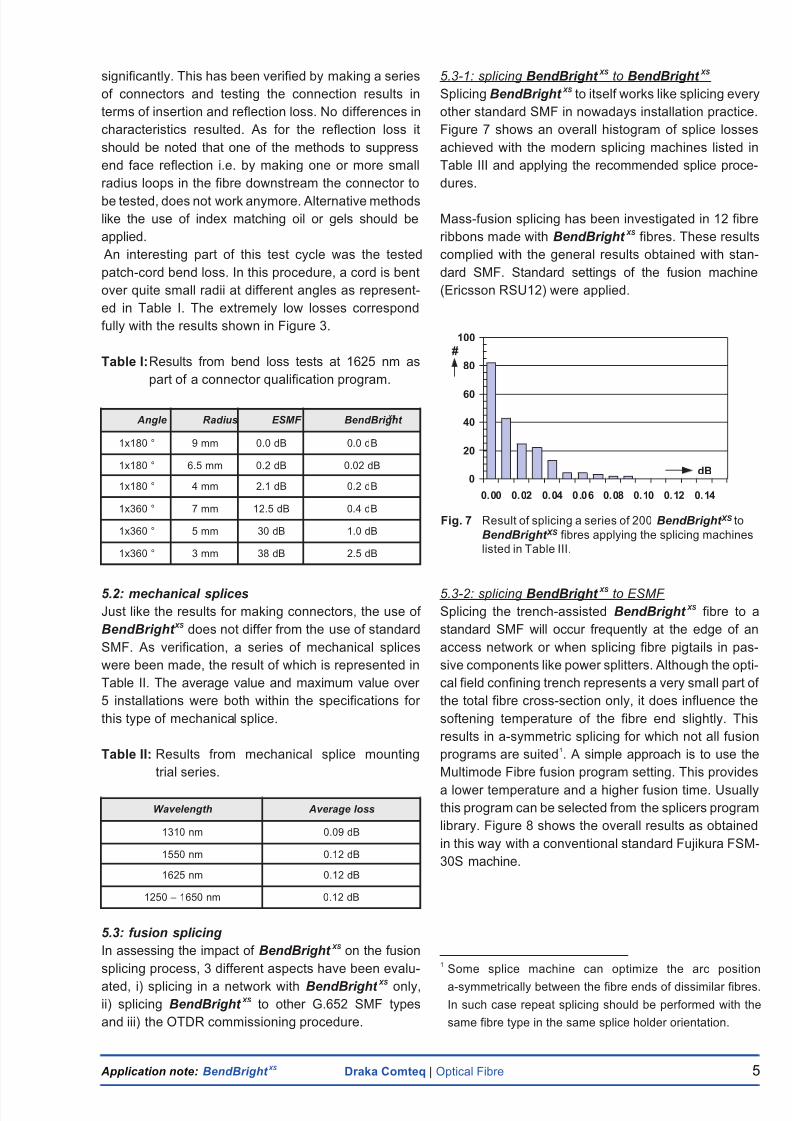
5.3-1: splicing BendBright XS to BendBright XS
Splicing BendBright XS to itself works like splicing every
other standard SMF in nowadays installation practice.
Figure 7 shows an overall histogram of splice losses
achieved with the modern splicing machines listed in
Table III and applying the recommended splice proce-
dures.
Mass-fusion splicing has been investigated in 12 fibre
ribbons made with BendBright XS fibres. These results
complied with the general results obtained with stan-
dard SMF. Standard settings of the fusion machine
(Ericsson RSU12) were applied.
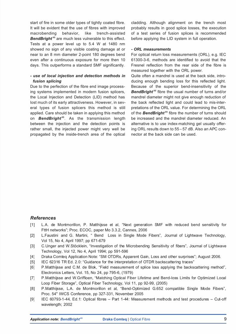
5.3-2: splicing BendBright XS to ESMF
Splicing the trench-assisted BendBright XS fibre to a
standard SMF will occur frequently at the edge of an
access network or when splicing fibre pigtails in pas-
sive components like power splitters. Although the opti-
cal field confining trench represents a very small part of
the total fibre cross-section only, it does influence the
softening temperature of the fibre end slightly. This
results in a-symmetric splicing for which not all fusion
programs are suited1. A simple approach is to use the
Multimode Fibre fusion program setting. This provides
a lower temperature and a higher fusion time. Usually
this program can be selected from the splicers program
library. Figure 8 shows the overall results as obtained
in this way with a conventional standard Fujikura FSM-
30S machine.
1Some splice machine can optimize the arc position
a-symmetrically between the fibre ends of dissimilar fibres.
In such case repeat splicing should be performed with the
same fibre type in the same splice holder orientation.
Angle Radius ESMF BendBright XS
1x180 ° 9 mm 0.0 dB 0.0 dB
1x180 ° 6.5 mm 0.2 dB 0.02 dB
1x180 ° 4 mm 2.1 dB 0.2 dB
1x360 ° 7 mm 12.5 dB 0.4 dB
1x360 ° 5 mm 30 dB 1.0 dB
1x360 ° 3 mm 38 dB 2.5 dB
Wavelength Average loss
1310 nm 0.09 dB
1550 nm 0.12 dB
1625 nm 0.12 dB
1250 – 1650 nm 0.12 dB
Fig. 7 Result of splicing a series of 200 BendBright XS to
BendBright XS fibres applying the splicing machines
listed in Table III.
dB0
20
40
60
80
100
0. 00 0. 02 0. 04 0 .0 6 0. 08 0. 10 0. 12 0. 14
#
8/2/2019 Bend Bright
http://slidepdf.com/reader/full/bend-bright 8/11
Application note: BendBright XS Draka Comteq | Optical Fibre 6
In a next refinement step, splicing machine manufac-
turers can optimize the settings in the fusion splicing
machines. Please contact Draka Comteq or the local
machine distributor for further details.
Although good results can be achieved with older
splicing sets applying the MMF arc settings, Draka
Comteq recommends applying modern splicers like
the ones listed in Table III. If relevant, automatic fibre
type recognition programs have to be switched off.
The close vicinity of the core and the surrounding
trench in BendBright XS requires too high resolution
from the current recognition programs.
Table III: Recommended machines for fusion splicing
of BendBright XS.
*) upgrade software for BendBright XS available via distributor
5.3-3: OTDR commissioning procedure
During installation, the splice loss is predicted by the
optical image processing system of the splicer unit.
Based on this prediction the splice can be approved or
rejected. When commissioning an optical link, splice
losses usually are checked again by OTDR testing
from either one side or from two sides of the fibre link.
For testing splices in networks with optical splitters
special procedures do exist.
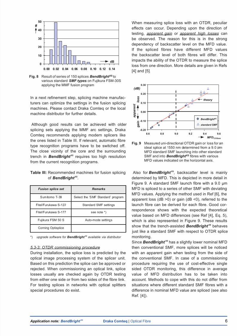
When measuring splice loss with an OTDR, peculiar
effects can occur. Depending upon the direction of
testing, apparent gain or apparent high losses can
be observed. The reason for this is in the strong
dependency of backscatter level on the MFD value.
If the spliced fibres have different MFD values
the backscatter level of both fibres will differ. This
impacts the ability of the OTDR to measure the splice
loss from one direction. More details are given in Refs
[4] and [5].
Also for BendBright XS, backscatter level is mainly
determined by MFD. This is depicted in more detail in
Figure 9. A standard SMF launch fibre with a 9.0 µm
MFD is spliced to a series of other SMF with deviating
MFD values. Applying the method used in Ref [6], the
Fusion splice set Remarks
Sumitomo T-39 Select the ‘SMF Standard’ program
Fitel/Furukawa S-122 Standard SMF settings
Fitel/Furukawa S-177 see note *)
Fujikura FSM 50 S Auto-mode settings
Corning Optisplice
Fig. 9 Measured uni-directional OTDR gain or loss for an
ideal splice at 1550 nm determined from a 9.0 m
MFD standard SMF launching into other standard
SMF and into BendBright XS fibres with various
MFD values indicated on the horizontal axis.
-0.20
-0.10
0.00
0.10
0.20
0.30
8.6 8.8 9.0 9.2 9.4 9.6
MFD1310nm
(dB)
standard SMF
BendBright XS a p p a r e n t
g a i n
l o s s
theory
apparent loss (dB >0) or gain (dB <0), referred to the
launch fibre can be derived for each fibre. Good cor-
respondence shows with the expected theoretical
value based on MFD differences (see Ref [4], Eq. 5),
which is also represented in Figure 9. These results
show that the trench-assisted BendBright XS behaves
just like a standard SMF with respect to OTDR splice
monitoring.
Since BendBright XS has a slightly lower nominal MFD
then conventional SMF, more splices will be noticed
with an apparent gain when testing from the side of
the conventional SMF. In case of a commissioning
procedure requiring the use of cost-effective single
sided OTDR monitoring, this difference in average
value of MFD distribution has to be taken into
account. Methods to cope with this do not differ from
situations where different standard SMF fibres with a
difference in nominal MFD value are spliced (see also
Ref. [4]).
Fig. 8 Result of series of 150 splices BendBright XS to
various standard SMF types on Fujikura FSM-30S
applying the MMF fusion program
dB0
10
20
30
40
50
0. 00 0. 02 0. 04 0. 06 0.08 0. 10 0. 12 0. 14
#

8/2/2019 Bend Bright
http://slidepdf.com/reader/full/bend-bright 9/11
Application note: BendBright XS Draka Comteq | Optical Fibre 7
When deploying SMF in storage cassettes or in case of
incidental bends, stress is applied to the outer circum-
ference of the fibre causing strain in the glass material
(see Figure 10).
Reducing the current minimum bend radius from 30
mm to 15 mm or even lower, might raise some ques-
tions on the lifetime of the fibre. For modern SMF
however, there is no reason for this concern. With
respect to strength, BendBright XS gets the same high
quality processing as the Draka Comteq standard
SMF. This is sufficient to guarantee its lifetime in all
situations in a telecom network, including access net-
works with much more rugged environments. To
explain this, let’s start with an assessment of current
strength requirements. These requirements have
been derived from a worst case network situation
defined as:
“all fibres in a cable observe over
the entire length and during the entire
lifetime of e.g. 20 years, a constant
strain of maximum 1/3 of the
1% proof-test value”
For modern optical fibres this requirement is met by
applying high quality materials and clean processes.
Verification is done by proof-testing the fibres resulting
in a sufficiently low number of breaks per preform pull.
Meeting this requirement for a 1% strain at proof-test,
insures that the fibre can withstand a 1/3 % strain over
its whole cross-section, length and lifetime.
When bending a fibre in a storage cassette the follow-
ing main considerations apply:
1- Usually there is no axial stress on the fibre, so
consequently the main cause for strain is the
bending itself. By simple geometrical rules it can
be calculated that a 1/3 % strain is reached at the
outer circumference of a 125 µm OD fibre for a
bend radius of 18.75 mm. Bending the fibre over
its whole length on this diameter will not impose
any additional impact on the lifetime compared
with the criteria mentioned above. On the con-
trary, the average stress is even less as the 1/3 %
strain is present in a very small part of the fiber’s
outer surface only.
2- The length of the bent fibre in a storage cassette
is a very short section of the total fibre length
only. So, the probability of failure is accordingly
lower.
Both considerations apply when calculating the failure
probability of a short fibre length stored in a cassette
of a fibre management system. In Ref. [7] a more com-
plete model has been described starting from the out-
side plant failure probability as indicated by the net-
work operator. For a rather extended network contain-
ing 5000 storage cassettes and a failure probability
per cassette of 0.001 % in 20 years, i.e. one single
spontaneous breakage in one of the cassettes in 20
years in 20 of these networks, the minimum bend
radius is represented in Figure 11.
It is evident that this minimum radius depends upon the
length of the stored fibre in the cassette. The other
parameter that governs the minimum bending radius is
the stress corrosion susceptibility n (fatigue parame-
ter). For BendBright XS the value of the “dynamic” sus-
ceptibility is >20 (see datasheet) whereas the “static”
value is >23. Note that the minimum dynamic stress
corrosion susceptibility coefficient is 18 according to
IEC product specification 60793-2-50 and Telcordia
GR-20-CORE specifications.
Depending upon the envisioned safety margin, differ-
ent values can be used. Since storage aging in most
5. Lifetime aspects
4
6
8
10
12
14
16
0 20 40 60 80 100
stored length (cm)
R m i n
( m m )
n = 18
20
23
29
Fig. 11 Minimum bending radius for storage of the
BendBright XS with a 20 years failure probability
of < 0.001 %
Fig. 10 Strain in the outer surface of the
fibre by bending the fibre axis
with a radius R
R
r
å = r / R
strain:
Fig. 10 Strain in the outer surface of the
fibre by bending the fibre axis
with a radius R
R
r
R
r
å = r / R
strain:
Fig. 10 Strain in the outer surface of the
fibre by bending the fibre axis
with a radius R
R
r
= r / R
strain:

8/2/2019 Bend Bright
http://slidepdf.com/reader/full/bend-bright 10/11
Application note: BendBright XS Draka Comteq | Optical Fibre 8
cases is a static phenomenon, the use of the higher
static fatigue parameter n=29 might be justified. The
lower value of n=18 might be used as a “worst case”.
Dependent upon these considerations the curves in
Figure 11 demonstrate that for this typical network and
the accepted very low failure rate a storage length of,
for example, 100 cm of fibre at a 15 mm radius is a safe
situation. However, storage of 100 cm of fibre at a
radius of 10 mm is also safe if the higher n-values are
ascertained *).
The curves in Figure 11 also show that for much lower
bend lengths, such as 90 degree bends in exit and
entrance ports of a fibre management system the min-
imum radius can be much shorter. Referring to the kink
loss situation as indicated in Figure 6, detailed calcula-
tions reveal that even in these cases, lifetime is not sig-
nificantly affected (see e.g. Ref. [8]; Fig. 9). A nice illus-
tration of this comes from a simple long term experi-
ment started at Draka Denmark in the early nineties of
the last century. A series of different diameter man-
drels, diameters ranging from 2.8 to 4.2 mm, 10 of
each and each mandrel with 30 windings were stored
in a room temperature environment. In the D=2.8 mm
and D=3.0 mm series mandrels 5 breaks occurred after
11 and 28 days, respectively. However, from the D> _
3.4 mm mandrels no breaks were detected up till now,
i.e. 16 years later!
In conclusion it can be stated that lifetime considera-
tions on fibres stored in short bend radius fibre man-
agement systems differ significantly from lifetime con-
siderations of cabled fibres. For storage in fibre man-
agement systems, a higher strain may be present on
short lengths, whereas for cables a lower strain and a
much longer length apply. As for lifetime prediction
however, similar calculation models can be applied.
*) Note that at this specific bend radius, the bend loss in “live”
fibres cannot be neglected anymore. For a for 100 cm storage
with a bend radius of 10 mm, the specified maximum bend loss
becomes as high as 0.8 dB at 1550 nm.
6. Miscellaneous
The improved macro-bending loss of BendBright XS
can also have impact on other areas.
- fibre and cable cut-off measurement.
In the cut-off region of a SMF, optical power is propa-
gated not only by the fundamental mode, but also by
higher order modes. For a standard step-index SMF
the two LP11 higher order modes are the dominant
ones just below the cut-off wavelength. In the bend
reference method of IEC and ITU-T standardized cut-
off wavelength test methods power is split in equal
parts over the three propagating modes. This results
in a spectral curve “hump” with a top value of
10xlog(3) = 4.7 dB. The cut-off wavelength follows
from the higher wavelength at 0.1 dB height of this
hump.
For trench-assisted BendBright XS, the cut-off phe-
nomena differ significantly from those for a conven-
tional step-index core profile SMF. As the bend loss of
the higher order modes is influenced by the trench
also, the wavelength width of the cutoff region is
broadened significantly leading to a much lower
“hump” value when applying the bend reference
method. In addition, due to interference undulation in
the measured cut-off curve can occur resulting in a
“dispersed hump” with a much lower maximum value,
even far below the minimum height of 2 dB as
required in the IEC standard for this test method.
Applying the multimode reference method (see Ref.
[9]) does not have this drawback and is recommend-
ed for this test, both for the fibre and for the cable cut-
off wavelength.
- use of fibre identifiers
The enhanced bending performance of BendBright XS
will diminish the signal received with fibre identifiers.
This might cause a sensitivity problem dependent
upon the type of use and the type of tap-off mecha-
nism. To investigate this, several identifiers were test-
ed:
- Tests with the Wilcom F 6225 identifier showed that
working with BendBright XS is possible with normal
identifier settings for both the 250 µm OD primary
coated fibre and a 2 mm buffered patch-cord.
- Tests with done also with the EXFO LFD-250 "clip-
on" detector and the LFD-300 FiberFinder. Both
work well as clip-on device to a sensitivity level of
about -30 dBm at 1550 nm. For providing the
appropriate power level software modifications will
be required.
- high power induced aging
In view of the foreseen up-grading of networks with
distributed or lumped Raman amplifiers, much atten-
tion is given currently to the effect of the use of high
power pump lasers at e.g. 1460 nm. An annoying side
effect might be that loss of power at low radius bends
can initiate an accelerated aging of the coating and in
some cases eventually lead to fibre breakage or even
8/2/2019 Bend Bright
http://slidepdf.com/reader/full/bend-bright 11/11
Application note: BendBright XS Draka Comteq | Optical Fibre 9
start of fire in some older types of tightly coated fibre.
It will be evident that the use of fibres with improved
macrobending behavior, like trench-assisted
BendBright XS are much less vulnerable to this effect.
Tests at a power level up to 5.4 W at 1480 nm
showed no sign of any visible coating damage at or
near to an 8 mm diameter 2-point 180 degrees bend
even after a continuous exposure for more then 10
days. This outperforms a standard SMF significantly.
- use of local injection and detection methods in
fusion splicing
Due to the perfection of the fibre end image process-
ing systems implemented in modern fusion splicers,
the Local Injection and Detection (LID) method has
lost much of its early attractiveness. However, in sev-
eral types of fusion splicers this method is still
applied. Care should be taken in applying this method
on BendBright XS. As the transmission length
between the injection and the detection points is
rather small, the injected power might very well be
propagated by the inside-trench area of the optical
cladding. Although alignment on the trench most
probably results in good splice losses, the execution
of a test series of fusion splices is recommended
before applying the LID system in full operation.
- ORL measurements
For optical return loss measurements (ORL), e.g. IEC
61300-3-6, methods are identified to avoid that the
Fresnel reflection from the rear side of the fibre is
measured together with the ORL power.
Quite often a mandrel is used at the back side, intro-
ducing enough bending loss for this reflected light.
Because of the superior bend-insensitivity of the
BendBright XS fibre the usual number of turns and/or
mandrel diameter might not give enough reduction of
the back reflected light and could lead to mis-inter-
pretations of the ORL value. For determining the ORL
of the BendBright XS fibre the number of turns should
be increased and the mandrel diameter reduced. An
alternative is to use index-matching gel usually offer-
ing ORL results down to 55– 57 dB. Also an APC con-
nector at the back side can be used.
References
[1] L.A. de Montmorillon, P. Matthijsse et al, “Next generation SMF with reduced bend sensitivity for
FttH networks”; Proc. ECOC, paper Mo 3.3.2, Cannes, 2006
[2] L.Faustini and G. Martini, “ Bend Loss in Single Mode Fibers”, Journal of Lightwave Technology,
Vol 15, No 4, April 1997; pp 671-679
[3] C.Unger and W.Stöcklein, “Investigation of the Microbending Sensitivity of fibers”, Journal of Lightwave
Technology, Vol 12, No 4, April 1994; pp 591-596
[4] Draka Comteq Application Note: “SM OTDRs, Apparent Gain, Loss and other surprises”; August 2006.
[5] IEC 62316 TR Ed. 2.0: “Guidance for the interpretation of OTDR backscattering traces”
[6] P.Matthijsse and C.M. de Blok, “Field measurement of splice loss applying the backscattering method”,
Electronics Letters, Vol. 15, No 24, pp 795-6, (1979)
[7] P.Matthijsse and W.Griffioen, “Matching Optical Fiber Lifetime and Bend-loss Limits for Optimized Local
Loop Fiber Storage”, Optical Fiber Technology, Vol 11, pp 92-99, (2005)
[8] P.Matthijsse, L.A. de Montmorillon et al, “Bend-Optimized G.652 compatible Single Mode Fibers”,
Proc. 54th IWCS Conference, pp 327-331, November 2005
[9] IEC 60793-1-44, Ed.1: Optical fibres – Part 1-44: Measurement methods and test procedures – Cut-off
wavelength; 2002