benchorkw in wood aourse c of studynd a...
TRANSCRIPT

BENCH WORK IN WOOD
A COURSE OF
STUDY AND PRACTICE
DESIGNED FOR THE USE OF SCHOOLS AND COLLEGES
BY
W. F. M. GOSS, M.S., D.Eng.
Dean of the Schools of Engineering, Purdue University
Lafayette, Indiana
REVISED EDITION
GINN & COMPANY
BOSTON - NEW YORK - CHICAGO - LONDON
Downlo
aded
from
wkFine
Tools
.com

Copyright, 1887, 1905, by
W. F. M. GOSS
ALL RIGHTS RESERVED
55.IO
GINN & COMPANY. PROPRIETORS . BOSTON • U.S.A.
Downlo
aded
from
wkFine
Tools
.com

S H
PREFACE.
TO avoid confusion, the subject herein treated is con
sidered in three divisions. Part I. contains the essen
tial facts concerning common bench tools for wood ; it
describes their action, explains their adjustments, and shows
how they may be kept in order. Part II. presents a course
of practice by which ability to use the tools may be ac
quired ; and Part III. discusses such forms and adaptations
of joints as will meet the requirements of ordinary construc
tion. It is not expected that the student will complete Part
I. before entering upon Part II., or that he will finish Part
II. before commencing Part III. He will find greater profit
in using them together. For example, a shop exercise involv
ing the chisel (Part II.) should be accompanied or preceded
by a study of the chisel (Part I.) ; again, the various forms
of mortise-and-tenon joints (Part III.) will be. better under
stood and more easily remembered, if considered during the
time when types of such joints are under construction in the
shops (Part II.). In the writer's experience with classes of
students, one hour has been given to class-room work for every
five hours given to shop work. By this apportionment, Parts
I. and III. can be mastered in the class-room while Part II.
is in progress in the shops.
The equipment necessary for carrying out the course of
Downlo
aded
from
wkFine
Tools
.com

iv PREFACE.
practice given in Part II. is much less expensive than may at
first appear. Besides a bench, a pair of trestles, and a bench-
hook, the following-named tools are needed : —
i 2-ft. Rule.
i Framing-Square.I 7-inch Try-Square.
1 8-inch Bevel.
2 8-inch Marking-Gauges,
i Chalk-Line, with Chalk,
i Lead-Pencil.
i Scriber.
Firmer-Chisels, i each, \", \",
sn in hi an ,n artA ,in
Gouges, i each, §", |", f", and
i».
i 22-inch Cross-cutting-Saw, 8
teeth.
I pair 8-inch Dividers.
I pair jj-inch Matching-Planes.
I T3s-inch Beading-Plane.
I J-inch Beading-Plane.
I Plow.
i 24-inch Ripping-Saw, 6 teeth.
1 10-inch Back-Saw.
1 8-inch Drawing-Knife.
1 Fore-Plane.
1 Jack-Plane.
1 Smooth-Plane.
1 Set Auger-Bits, \" to 1" by
i6ths.1 Bit-Brace.1 Brad-Awl.1 Carpenter's Hammer.1 Mallet.1 Nail-Set.1 Oilstone.
I Hand-Scraper.
J doz. Quill Bits, assorted from \"
down.
1 Miter-Box.
I Grindstone.
If provision is to be made for more than one student, the
items printed in small type need not be duplicated. One set
of these will suffice for any number less than thirty.
The writer is indebted to Mr. M. Golden, of the School
of Mechanics and Engineering, Purdue University, for the exe
cution of many of the drawings and for valuable suggestions.
W. F. M. G.
Purdue University,
Lafayette, Ind.
1887
Downlo
aded
from
wkFine
Tools
.com
PREFACE TO SECOND EDITION.
In the preparation of this edition the text has been revised
and a new section dealing with timber and its preparation for
use has been added. This appears as Part IV and, in common
with Parts I and III, is designed for use in connection with the
course of practice outlined in Part II. Use has been made of
Snow's " Principal Species of Wood," from which several of the
illustrations of Part IV have been taken or adapted, and also
of certain publications of the United States government, espe
cially those prepared by Professor C. S. Sargent and Dr. B. E.
Fernow.
Downlo
aded
from
wkFine
Tools
.com

CONTENTS.
INTRODUCTION. — INTERPRETATION OF
MECHANICAL DRAWINGS.
PAGES
I. Mechanical Drawings Defined. — 2. Plans. — 3. Elevations. —
4. Method of showing Parts Obscured from Sight. — 5. Sections.
Section Lines. Cross-hatching. Incomplete Sections. — 6. Bro
ken Drawings. — 7. Scale. — 8. Dimensions. Dimension Lines, 1-6
PART I. — BENCH TOOLS.
9. Bench. — 10. Bench-Stop. — 11. Vise. — 12. Bench-Hook.—
13. Trestles 7-9
Measuring and Lining Appliances.
14. Early Standards of Length.— 15. English Standard Yard. — 1 6.
United States Standard of Length. — 17. The Troughton Scale.
— 18. Rules. — 19. Framing-Square. — 20. Board-measure Table.
— 21. Brace-measure Table. — 22. Try-Square. — 23. Bevel. —
24. "Miter-Square." — 25. Try-and-" Miter " Square. — 26. Di
viders. — 27. Scribing with Dividers. — 28. Combining Square
and Rule. — 29. Combining Square and Bevel. — 30. Setting
the Bevel at an Angle of 60 Degrees. — 31. Setting the Bevel at
any Given Angle. — 32. Marking-Gauge. — 33. Mortise-Gauge.
— 34. Panel-Gauge. — 35. Cutting-Gauge. — 36. Chalk-Line.
— 37. Scriber. — 38. Pencil 9-20
Downlo
aded
from
wkFine
Tools
.com
viii CONTENTS.
PAGES
Chisels and Chisel-like Tools.
39. Firmer-Chisels. — 40. Framing-Chisels.— 41. Corner-Chisels. —
42. Gouges. — 43. Chisel Handles. — 44. Drawing-Knife. — 45.
Action of Cutting Wedges. — 46. Angle of Cutting Wedge in
Chisel and Gouge. — 47. Grinding. — 48, Whetting , . . 20-26
Saws.
49. Efficiency. — 50. Form. — 51. Set. — 52. Size of Teeth. — 53.
Ripping-Saw and Cross-Cutting-Saw Defined. — 54. Teeth of
Ripping-Saws. — 55. Teeth of Cross-Cutting-Saws. — 56. Back-
Saw. — 57. Compass-Saw 26-36
Appliances for Filing and Setting Saws.
58. Files. — 59. Sets for Bending the Tooth. — 60. Sets for Swedging
the Tooth. — 61. Clamps 36-38
Saw Filing and Setting.
62 Top-Jointing. — 63. Setting. — 64. Filing. — 65. Side-Jointing, 39-41
Planes and Plane-like Tools.
66. Description of Planes. — 67. Length of Stock. — 68. Plane-Iron.
Angle of Cutting Wedge. — 69. Outline of Cutting Edge. — 70.
Use of Different Bench Planes. — 71. Action of Smooth- Plane
and Fore-Plane Compared. — 72. The Cap. — 73. Narrowness of
Mouth. — 74. Adjusting the Iron.— 75. Jointing a Plane. — 76.
Iron Planes. — 77. Planes of Wood and Iron Combined.— 78.
Circular-Planes. — 79. Block-Planes. — 80. Spokeshaves. — 81.
Rabbeting- Planes. — 82. Matching-Planes. — 83. Hollows and
Rounds. — 84. Beading-Planes. — 85. Plows. — 86. Combina
tion Planes. — 87. Scrapers 41-52
Boring Tools.
88. Augers. — 89. Auger-Bits. — 90. Sharpening Augers and Auger-
Bits. — 91. Center-Bits. — 92. Expansive Bits. — 93. Small Bits.
— 94. Bit-Braces. — 95. Angular Bit-Stock. — 96. Automatic
Boring Tool 53~59
Downlo
aded
from
wkFine
Tools
.com
CONTENTS. ix
FACES
Miscellaneous Tools.
97. Winding-Sticks. — 98. Hand Screw-Driver.— 99. Brace Screw-
Driver. — 100. Hammer. — 101. Hatchet. — 102. Mallet. —
103. Sand-Paper. — 104. Wooden Miter-Box. — 105. Iron
Miter-Box. — 106. Clamps. — 107. Grindstone. — 108. Use of
Water on a Grindstone. — 109. Truing a Grindstone. — no.
Truing Devices for Grindstones. — in. Oilstones. — 112. Oil
for Oilstones. — 113. Form of Oilstones. — 114. Oilstone Slips.
— 115. Truing an Oilstone 59-69
PART II. — BENCH WORK.
[16. Good Lines a Necessity. — 117. Location of Points. — 118.
Jointed Face. — 119. Working-Face 71—73
EXERCISE No. 1. — Measuring and Lining.
120. Material. — 121. Spacing: Pencil and Rule. — 122. Lining:
Pencil, and Framing-Square.— 123. Chalk-Lining. — 1 24. Lin
ing: Pencil, and Try-Square. — 125. Lining: Pencil and Bevel.
— 126. "Gauging" Lines: Pencil and Rule. — 127. Spacing:
Scriber and Rule. — 1 28. Lining : Scriber, and Try-Square.
129. Lining: Scriber and Bevel. — 130. Gauge-Lining. — 131.
Lining for Exercise No. 3 73~79
EXERCISE No. 2. — Chiseling and Gouging.
132. Chiseling by Hand. — 133. Chiseling by Use of Mallet. — 134.
Gouging 80-83
EXERCISE No. 3. — Sawing.
135. Handling the Saw. — 136. Guiding the Saw. — 137. Correct
ing the Angle of the Cut. — 138. Rip-Sawing. — 139. Cross-
cutting 83-86
EXERCISE No. 4. — Planing.
140. Handling the Plane. — 141. Why a Plane Clogs. — 142. Joint
ing. — 143. Planing to a Square. — 144. Method of Performing
Downlo
aded
from
wkFine
Tools
.com
X CONTENTS.
PAGES
Similar Operations. — 145. Smooth Surfaces. — 146. Sand-
EXERCISE No. 5. — Box.
147. Jointing to Width. — 148. Sawing to Length. — 149. Nailing.
— 150. Hammer Marks. — 151. Setting Nails. — 152. With
drawing Nails. — 153. Fastening the Box Bottom. Finishing
EXERCISE No. 6. — Bench-Hook.
155. lining and Sawing. — 156. Using the Auger-Bit .... 96-98
EXERCISE No. 7. — Halved Splice.
157. Lining. — 158. Value of Working-Face Illustrated. — 159. Cut
ting the Joint. — 160. Sawing a Fit. — 161. Toeing Nails . 99-102
EXERCISE No. 8. — Splayed Splice.
162. Lining. — 163. Cutting and Finishing the Joint .... 103, 104
EXERCISE No. 9 — Simple Mortise-and-Tenon Joint.164. Lining. — 165. Cutting the Mortise. — 166. Cutting the Tenon.
167. Making a Pin. — 168. Drawboring 104-110
EXERCISE No. 10. — Keyed Mortise-and-Tenon Joint.
169. Lining and Cutting. — 170. Key 110, III
EXERCISE No. 11. — Plain Dovetail.
171. Lining and Cutting. — 172. Gluing. — 173. Short Method of
Lining and Cutting the Joint . . 1 1 2, 1 1 3
Papering 86-91
the Box. — 154. Planing End Grain ■. 91-96EXERCISE No. 12. — Lap Dovetail.
174. Lining and Cutting 1 14, 1 15
Downlo
aded
from
wkFine
Tools
.com

CONTENTS. xi
PAGES
EXERCISE No. 13. — Blind Dovetail.
175. Liningand Cutting. — 176. A Modified Form of the Joint . 115-117
EXERCISE No. 14. — Frame and Panel.
177. Panel Door Described. — 178. Making the Joint between Stile
and Rail. — 179. Cutting Chamfers. — 180. Keying the Joint.
— 181. Finishing the Panel. Fastening Panel to Frame. —
182. Inserting Screws.— 183. Using the Brad-Awl . . 1-17-121
EXERCISE No. 15. — Frame and Panel.
184. Making Joint between Stile and Rail. — 185. Plowing.— 186.
Beading.— 187. Forming the Panel 121-124
PART III. — ELEMENTS OF WOOD CON
STRUCTION.
CARPENTRY.
188. Work of Carpenter and Joiner Compared. — 189. Congres
sional, Tensional, and Transverse Stress Defined.— 190. Effect
of Transverse Stress. Neutral Axis. Relation between the
Depth of a Timber and its Resistance to Transverse Stress.
— 191. Rankine's Principles concerning Joints and Fasten
ings 125-128
Joints Connecting Timbers in the Direction of their Length.
192. Lapped Joint. — 193. Fished Joint. — 194. Scarfed Joints. —
195. Scarfed Joint for Resisting Compression. — 196. Scarfed
Joint for Resisting Tension. — 1 97. Scarfed Joint for Resisting
Transverse Stresses. — 198. Scarfed Joint for Resisting Ten
sion and Compression. — 199. Scarfed Joint for Resisting
Tension and Transverse Stress 1 28-1 31
Downlo
aded
from
wkFine
Tools
.com
xii CONTENTS.
Joints Connecting Timbers at Right Angles.
200. Halving. — 201. Notching. — 202. Cogging. — 203. Mortise-
and-Tenon Joints. — 204. Mortise and Tenon Joining a Vertical
to a Horizontal Timber. — 205. Mortise and Tenon Joining
a Horizontal to a Vertical Timber. — 206. Mortise and Tenon
Joining One Horizontal Timber to Another. Tusk Tenon 131 -135
Miscellaneous Joints.
207. Oblique Mortise and Tenon. — 208. Bridle Joint. — 209. Tie
Joint. — 210. Chase Mortise I3S_r37
JOINERY.
211. Joinery Described 137
Beads and Moldings.
212. Beads.— 213. Use of Beads. — 214. Chamfer. — 215. Stop
Chamfer. — 216. Moldings Described. — 217. Round Nose. —
218. Some Typical Forms of Moldings. Fillet. — 219. Joints
in Joinery Defined 138-140
Heading-Joints, or Joints Uniting Pieces in the Direction of
their Length.
220. Square Heading-Joint. Splayed Heading-Joint 141
Joints Uniting Pieces in Direction of their Width.
221. Their Office. — 222. Butt Joint. Filleted Joint. Rabbeted
Joint. Matched Joint.— 223. Glued Butt Joint.— 224. deal
ing. — 225. Side Cleats. — 226. End Cleats. — 227. Relieving
Cleats from Strain 141-144
Downlo
aded
from
wkFine
Tools
.com
CONTENTS. xiii
Joints Uniting Pieces at Right Angles.
228. Butt Joint. — 229. Miter Joint. — 230. Strengthening of Miter
Joints. — 231. Dovetail Joints. — 232. Proportions of Mortise-
and-Tenon Joints. — 233. Single and Double Tenons. — 234.
Haunching.— 235. Four Tenons.— 236. Mortises and Tenons
at an Angle in the Work. — 237. Modifications of Mortise-and-
Tenon Joints 144-148
Paneling.
238. Panel. — 239. Frame. — 240. Joints between Panel and
Frame 1 48-1 51
FASTENINGS.
241. Pins. — 242. Wedges. — 243. Blind-Wedging. — 244. Keys. —
245. Dowels. — 246. Nails.— 247. Size of Nails. — 248. Brads.
— 249. Tacks. — 250. Screws. — 251. Glue . . . . ^_ 151-157
PART IV.—TIMBER AND ITS PREPARATION
FOR USE.
Timber.
252. Timber. — 253. Structure of Wood. — 254. Markings of
Wood. — 255. Adaptability of Various Woods . . . 158-166
Characteristics of Typical Timber-Yielding Trees.
256. Classification of Trees. — 257. Exogens.— 258. Effect of En
vironment. — 259. Broad-Leaved Woods. — 260. Oak. — 261.
White Oak. — 262. Red Oak. — 263. Maple. — 264. Sugar
Maple. — 265. Silver or White Maple. — 266. Black Walnut.
— 267. Yellow Poplar.— 268. Beech. — 269. Ash.— 270. White
Ash.— 271. Needle-Leaved Woods.— 272. Pine.— 273. White
Downlo
aded
from
wkFine
Tools
.com
xiv CONTENTS.
Pine. — 274. Long-Leaved Pine. — 275. Short-Leaved Pine.
— 276. Loblolly Pine. — 277. Bull Pine. — 278. The Spruces.
— 279. Black Spruce. — 280. White Spruce. — 281. Hemlock.
— 282. Eastern Hemlock. — 283. Western Hemlock. — 284.
Bald Cypress. — 285. The Common Redwood. — 286. The
Big-Tree Variety of Redwood 166-182
Logging.
287. Felling Timber. — 288. Transportation of Logs. — 289. Saw
mills. — 290. Process of Sawing. — 291. Milling. — 292. Wa
ter in Timber. — 293. Process of Seasoning. — 294. Air
Seasoning. — 295. Steam Drying. — 296. Water Seasoning.
— 297. Kiln Drying. — 298. Kilns. — 299. Shrinkage. — 300.
Swelling. — 301. Warping. — 302. Decay in Wood. — 303.
Timber Preservation. — 304. Creosoting 182-198
Strength of Timber.
305. Strength of Timber. — 306. Strength in Tension. — 307.
Strength in Compression. — 308. Strength in Shear. — 309.
Strength under Transverse Loads 198-200
Downlo
aded
from
wkFine
Tools
.com
INTRODUCTION.
INTERPRETATION OP MECHANICAL DRAWINGS.
i. Most of the illustrations presented with the following
chapters are in the form of Mechanical Drawings. To the
novice, these may appear confusing ; but careful attention to
some of- the principles underlying their con- Fig. 1
struction will enable him readily to interpret
their meaning.
A mechanical drawing, as distinguished from
a perspective drawing, or picture, instead of
giving all the characteristics of an object at a
glance, presents them in detail, giving in one
view one set of elements, in another view another set of
elements, and so on, until the form of the ob
ject is accurately defined.
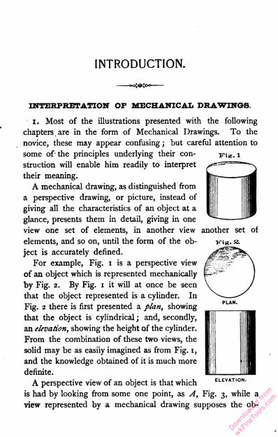
For example, Fig. i is a perspective view
of an object which is represented mechanically
by Fig. 2. By Fig. i it will at once be seen
that the object represented is a cylinder. In
Fig. 2 there is first presented a plan, showing
that the object is cylindrical ; and, secondly,
an elevation, showing the height of the cylinder.
From the combination of these two views, the
solid may be as easily imagined as from Fig. i,
and the knowledge obtained of it is much more
definite.
A perspective view of an object is that which
is had by looking from some one point, as A, Fig. 3, while a
view represented by a mechanical drawing supposes the ob-
ELEVATION.
Downlo
aded
from
wkFine
Tools
.com
2 BENCH WORK IN WOOD.
server to be looking from an infinite number of points, and
always in parallel lines, as indicated by A, Fig. 4.
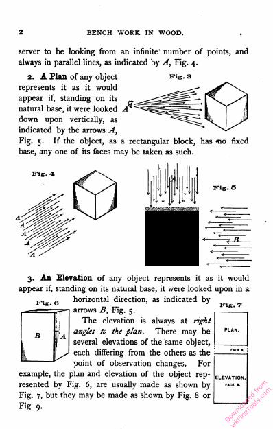
2. A Plaji of any object Fig. 3represents it as it would
appear if, standing on its
natural base, it were looked
down upon vertically, as
indicated by the arrows A,
Fig. 5. If the object, as a rectangular block, has -no fixed
base, any one of its faces may be taken as such.
vie- t
3. An Elevation of any object represents it as it would
appear if, standing on its natural base, it were looked upon in a
horizontal direction, as indicated by
arrows B, Fig. 5.
The elevation is always at right
angles to the plan. There may be
several elevations of the same object,
each differing from the others as the
point of observation changes. For
example, the plan and elevation of the object rep
resented by Fig. 6, are usually made as shown by
Fig. 7, but they may be made as shown by Fig. 8 or
Fig. 9.
ll
a
BM
fi. V
ELEVATION,
Downlo
aded
from
wkFine
Tools
.com
INTRODUCTION.3
Fig. 8
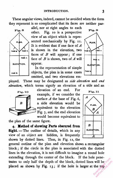
These angular views, indeed, cannot be avoided when the form
they represent is so complicated that its faces are neither par
allel, nor at right angles to each
other. Fig. 10 is a perspective
view of an object which is repre
sented mechanically by Fig. 11.
It is evident that if one face of A
is shown in the elevation, two
faces of B will appear ; if one
face of B is shown, two of A will
appear.
In the representation of simple
objects, the plan is in some cases
omitted, and two elevations em
ployed. These may be designated as side elevation and end
elevation, which terms signify an elevation of a side and an
elevation of an end. For
example, if we consider the
surface A the base of Fig. 6,
a side elevation would be
equivalent to the elevation
Fig. 7, and the end elevation
would become equivalent to
the plan of the same figure.
4. Method of showing Farts obscured from
Sight. —The outline of details, which in any
view of an object are hidden, is frequently
shown by dotted lines. Thus, in Fig. 12, the
general outline of the plan and elevation shows a rectangular
block ; if the circle in the plan is associated with the dotted
lines in the elevation, it is not difficult to imagine a round hole
extending through the center of the block. If the hole pene
trates to only half the depth of the block, dotted lines will be
placed as shown by Fig. 13; if the hole is larger at the top
Fig. 11
A y\
f PLAN. y
Downlo
aded
from
wkFine
Tools
.com
4 BENCH WORK IN WOOD.
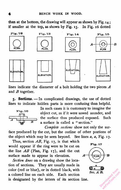
than at the bottom, the drawing will appear as shown by Fig. 14 ;
if smaller at the top, as shown by Fig. 15. In Fig. 16 dotted
Fig. IS Fig, 13 Fig. 14 Fig. IS
OPLAN. OPLAN. ®
A—
PLAN. PLAN
—B
ELEVATION
Fig. IO
lines indicate the diameter of a bolt holding the two pieces A
and B together.
5. Sections. — In complicated drawings, the use of dotted
lines to indicate hidden parts is more confusing than helpful.
In such cases it is customary to imagine the
object cut, as if it were sawed asunder, and
the surface thus produced exposed. Such
a surface is called a " section."
Complete sections show not only the sur
face produced by the cut, but the outline of other portions of
the object which may be seen beyond. See lines a, a, Fig. 1 7.
Thus, section AB, Fig. 1 7, is that which
would appear if the ring were to be cut on
the line AB (Plan, Fig. 17), and the cut
surface made to appear in elevation.
Section lines on a drawing show the loca
tion of sections. They are usually made in
color (red or blue), or in dotted black, with
a colored line on each side. Each section
is designated by the letters of its section line.
Sec. A B.
Downlo
aded
from
wkFine
Tools
.com
INTRODUCTION. 5
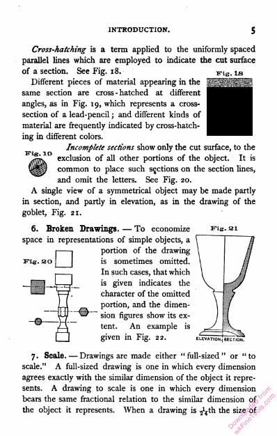
Cross-hatching is a term applied to the uniformly spaced
parallel lines which are employed to indicate the cut surface
of a section. See Fig. 18.
Different pieces of material appearing in the
same section are cross-hatched at different
angles, as in Fig. 19, which represents a cross-
section of a lead-pencil ; and different kinds of
material are frequently indicated by cross-hatch
ing in different colors.
Incomplete sections show only the cut surface, to the
exclusion of all other portions of the object. It is
common to place such sections on the section lines,
and omit the letters. See Fig. 20.
A single view of a symmetrical object may be made partly
in section, and partly in elevation, as in the drawing of the
goblet, Fig. 21.
EHg. 10
Vig. 3
6. Broken Drawings. — To economize
space in representations of simple objects, a
portion of the drawing
is sometimes omitted.
In such cases, that which
J_ I I . _ J is given indicates the
™™ 1—1 character of the omittedportion, and the dimen
sion figures show its ex
tent. An example is
given in Fig. 22.
Fig. 31
ELEVATION.) SECTION.
7. Scale. — Drawings are made either "full-sized" or "to
scale." A full-sized drawing is one in which every dimension
agrees exactly with the similar dimension of the object it repre
sents. A drawing to scale is one in which every dimension
bears the same fractional relation to the similar dimension of
the object it represents. When a drawing is ^?th the size of
Downlo
aded
from
wkFine
Tools
.com

6 BENCH WORK IN WOOD.
the object, it is said to be on a scale of £ inch to the foot, or,
as frequently written, £ in. = 1 ft. ; if £th the size, as 2 in. = 1 ft.,
and so on. The scale 6 in. = 1 ft. is often expressed as " half
size."
8. Dimensions. —The various dimensions of an object repre
sented are shown on the drawing by appropriate figures, which
Fig. as express feet when followed by ', and inches
jjjjjl when followed by ". Thus 2' should be read
tf « as two feet, and 2" as two inches. 12' 7J" is
h»lf size. the same as twelve feet and seven and three-
quarters inches.
The figures always show the dimensions of the thing repre
sented ; they do not agree with the dimensions of the drawing
except when the latter is full-sized. See dimension figures in
Fig. 23.
Dimension lines,—Dimension figures are always placed on, or
near, lines along which they apply. In drawings these lines are
usually in color (red), but may be dotted black, as in Fig. 23.
When convenient, they are placed within the outline of the
drawing ; but if the drawing is small or crowded, they are placed
at one side, and are connected with the parts they limit by per
pendicular, colored or dotted lines. Two arrow-heads, one on
each side of the dimension figure, locate the points between
which it applies. Several dimensions may be given on the same
line, each being limited by its own arrow-heads.
Downlo
aded
from
wkFine
Tools
.com
PART I.
BENCH TOOLS.
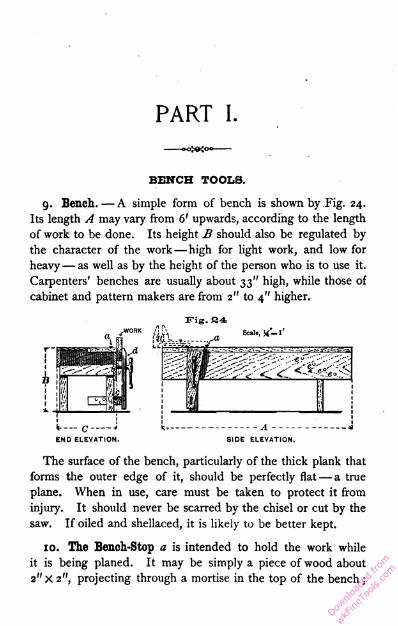
9. Bench. — A simple form of bench is shown by Fig. 24.
Its length A may vary from 6' upwards, according to the length
of work to be done. Its height B should also be regulated by
the character of the work—high for light work, and low for
heavy— as well as by the height of the person who is to use it.
Carpenters' benches are usually about 33" high, while those of
cabinet and pattern makers are from 2" to 4" higher.
Fig. 34
Scale, X— l'
c—*
END ELEVATION.
1
I
1SIDE ELEVATION,
The surface of the bench, particularly of the thick plank that
forms the outer edge of it, should be perfectly flat — a true
plane. When in use, care must be taken to protect it from
injury. It should never be scarred by the chisel or cut by the
saw. If oiled and shellaced, it is likely to be better kept.
10. The Bench-Stop a is intended to hold the work while
it is being planed. It may be simply a piece of wood about
2" X 2", projecting through a mortise in the top of the bench ;
Downlo
aded
from
wkFine
Tools
.com

8 BENCH WORK IN WOOD.
but it is far better to have some form of iron fitting, many of
which are supplied by the trade. The char
acteristics of all of them are well illustrated
by the one shown in Fig. 25. The frame
A is let into the bench even with its sur
face. The hook C is held in position at
any height above the bench by the action
of the screw B. C may be fastened even
with the surface of the bench, or removed
entirely.
11. The Vise d, Fig. 24, is of a form that, for general pur
poses, has long been in use. To hold the work well, the jaw d
should be as nearly as possible parallel to the face g, against
which it acts. If it is not parallel, the space between should
be less at the top than at the bot
tom — an arrangement which in
sures a much better grip upon the
work than the opposite conditions.
Adjustments for parallelism are
made by changing the pin c from
one hole to another. Iron vises
can now be had which are adapted
to the same uses with the one just
described ; they can be quickly adjusted, they are so designed
that the clamping faces always maintain their parallelism, and
being stiffer than wooden vises, they can be depended upon to
hold work more securely.
An iron bench vise, such as is shown by Fig. 2 6, is extremely
useful for small work, and, if expense is not to be ' considered,
should supplement the vise d, in which case it may be located
on the bench at H.
The holes, <?, in the bench are for the reception of a plug,
which may be used to support one end of a long piece of work
while the other end is held by the vise.
Downlo
aded
from
wkFine
Tools
.com

BENCH TOOLS.9
12. A Bench-Hook, Fig. 178, applied to the bench as
shown by Fig. 167, provides a stop to prevent work from
sliding across the bench. The flat faces which rest on the
bench and receive the work, should be true planes and par
allel. A length of from 14" to 16" is convenient, though
bench-workers frequently have several of different lengths.
13. Trestles, or "horses," are used in various ways to sup
port material, and also
to take the place of the f—
bench when large pieces
of material are to be Bj.
operated upon. A con- mi
venient form is shown j/ij
by Fig. 27.
Measuring and Lining Appliances.
14. Early Standards of Length. — To meet the earliest
need of units of measure, it was natural to adopt the means
nearest at hand, and common consent, no doubt, brought into
use the pace, the forearm, or cubit, the foot, the hand, the nail,
etc. These were certainly convenient enough, for wherever he
might go, every individual carried his units of measure with him.
Variations in their length, however, were inevitable, and many
attempts were made to reduce them to a standard. An old
English statute, the substance of which has descended to
American arithmetics of modern date, enacts "that three
barleycorns, round and dry, make an inch, twelve inches make
a foot, three feet a yard, etc. ; and there seems to be no doubt
that this mode of obtaining a standard was actually resorted to.
But setting aside the objection due to the varying size of the
individual grains, — unless the average of a large number be
taken, — it is so difficult to know how much of the sharp end
of a grain of barley must be removed to make it ' round,' that
Downlo
aded
from
wkFine
Tools
.com

10 BENCH WORK IN WOOD.
the definition is not of much value. Nevertheless, in spite
of numerous attempts at legislation on the subject, this, down
to the year 1824, was the only process by which the standard
yard of this country [England] could, if lost, be legally re
covered." 1
Previous to the institution of a national standard of length
in Great Britain, influential men and prominent societies pro
vided themselves with so-called standards, which were accepted
and used in different localities. By comparison with many of
these, the present standard of length was made, and its length
defined by law as the British standard yard. From this, about
fifty copies have been made. Two of these copies were in 1855
sent to the United States, and have since been in the keeping
of the Coast Survey. They are described as follows : —
15. "Each standard of length is a solid bar 38 inches long
and 1 inch square, in transverse section. One inch from each
extremity a cylindrical well, one-half inch in diameter, is sunk
one-half inch below the surface. At the bottom of the wells,
in each bar, is a gold pin about 0.1 inch in diameter, upon
which are drawn three transversal and two longitudinal lines.
The wells are protected by metal caps. The length of one
English yard at a specified temperature is defined by the dis
tance from the middle transversal line in one well to the middle
transversal line in the other, using the parts of those lines which
are midway between the longitudinal lines." 2
16. The United States Standard of Length. — " The stand
ard yard of Great Britain was lawful in the colonies before
1776. By the Constitution of the United States the Congress
is charged with fixing the standard of weights and measures,
but no such enactment has ever been made by Congress, and
1 Shelley's " Workshop Appliances."
a Report of the United States Coast Survey, 1877, Appendix No. 12.
Downlo
aded
from
wkFine
Tools
.com
BENCH TOOLS. II
therefore that yard which was standard in England previous to
1776 remains the standard yard of the United*' States to this
day." 1
17. "The Troughton Scale is a bronze bar with an inlaid
silver scale, made for the survey of the coast of the United
States by Troughton, of London. The bar is nearly 86 inches
long, 2^ inches wide, and one-half inch thick. A thin strip of
silver, a little more than 0.1 inch wide, is inlaid with its surface
flush with the brass, midway the width of the bar. It extends
the whole length of the bar, save where it is interrupted by two
perforations, one near each end. Two parallel lines about 0.1
inch apart are ruled longitudinally on the silver. The space
between them is divided transversely into tenths of inches.
"The zero mark of the graduations is about 3.2 inches from
one end of the bar. Immediately over it is engraved an eagle,
surmounted by the motto, E Pluribus Unum, and thirteen
stars. Below the 38 to 42-inch divisions is engraved 'Troughton,
London, 18 14.' The bar is also perforated by a hole above
the scale and near the 40-inch division, and by one below it,
between the words ' Troughton ' and ' London.' . . .
"The yard of 36 inches, comprised between the 27th and
63d inch of the Troughton scale, which was found by Hassler's
comparison to be equal to the average 36 inches of the scale, is
the actual standard yard of the United States, having been
adopted by the Treasury Department as such in 1832, on the
recommendation of Mr. Hassler.2"1
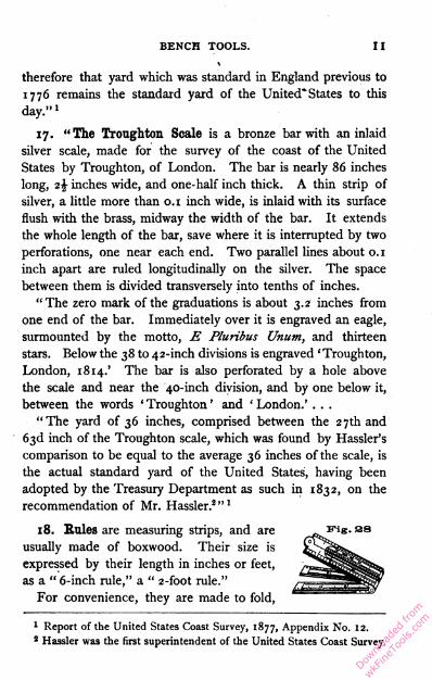
18. Rules are measuring strips, and are
usually made of boxwood. Their size is
expressed by their length in inches or feet,
as a " 6-inch rule," a " 2-foot rule."
For convenience, they are made to fold,
1 Report of the United States Coast Survey, 1877, Appendix No. 12.
2 Hassler was the first superintendent of the United States Coast Survey,
Downlo
aded
from
wkFine
Tools
.com
12 BENCH WORK IN WOOD.
•Wl,'"lV'-'i,-i'-«l'U'i«y>'yi>|,'
kulnliiuiuiL
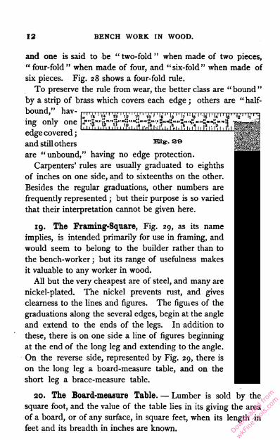
and one is said to be " two-fold " when made of two pieces,
" four-fold " when made of four, and "six-fold" when made of
six pieces. Fig. 28 shows a four-fold rule.
To preserve the rule from wear, the better class are "bound "
by a strip of brass which covers each edge ; others are " half-
bound," hav
ing only one
edge covered ;
and still others Eig.se
are "unbound," having no edge protection.
Carpenters' rules are usually graduated to eighths
of inches on one side, and to sixteenths on the other.
Besides the regular graduations, other numbers are
frequently represented ; but their purpose is so varied
that their interpretation cannot be given here.
19. The Framing-Square, Fig. 29, as its name
implies, is intended primarily for use in framing, and
would seem to belong to the builder rather than to
the bench-worker ; but its range of usefulness makes
it valuable to any worker in wood.
All but the very cheapest are of steel, and many are
nickel-plated. The nickel prevents rust, and gives
clearness to the lines and figures. The figures of the
graduations along the several edges, begin at the angle
and extend to the ends of the legs. In addition to
these, there is on one side a line of figures beginning
at the end of the long leg and extending to the angle.
On the reverse side, represented by Fig. 29, there is
on the long leg a board-measure table, and on the
short leg a brace-measure table.
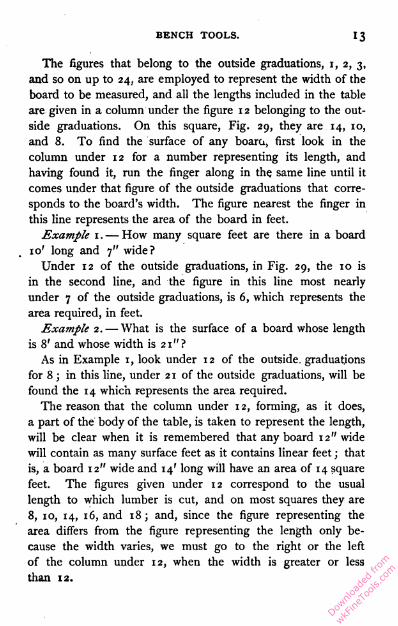
20. The Board-measure Table. — Lumber is sold by the
square foot, and the value of the table lies in its giving the area
of a board, or of any surface, in square feet, when its length in
feet and its breadth in inches are known.
Downlo
aded
from
wkFine
Tools
.com
BENCH TOOLS. 13
The figures that belong to the outside graduations, x, 2, 3,
and so on up to 24, are employed to represent the width of the
board to be measured, and all the lengths included in the table
are given in a column under the figure 1 2 belonging to the out
side graduations. On this square, Fig. 29, they are 14, 10,
and 8. To find the surface of any boara, first look in the
column under 12 for a number representing its length, and
having found it, run the finger along in the. same line until it
comes under that figure of the outside graduations that corre
sponds to the board's width. The figure nearest the finger in
this line represents the area of the board in feet.
Example 1 . — How many square feet are there in a board
10' long and 7" wide?
Under 12 of the outside graduations, in Fig. 29, the 10 is
in the second line, and the figure in this line most nearly
under 7 of the outside graduations, is 6, which represents the
area required, in feet.
Example 2. — What is the surface of a board whose length
is 8' and whose width is 21"?
As in Example 1, look under 12 of the outside, graduations
for 8 ; in this line, under 2 1 of the outside graduations, will be
found the 14 which represents the area required.
The reason that the column under 12, forming, as it does,
a part of the body of the table, is taken to represent the length,
will be clear when it is remembered that any board 12" wide
will contain as many surface feet as it contains linear feet ; that
is, a board 12" wide and 14' long will have an area of 14 square
feet. The figures given under 12 correspond to the usual
length to which lumber is cut, and on most squares they are
8, 10, 14, 16, and 18; and, since the figure representing the
area differs from the figure representing the length only be
cause the width varies, we must go to the right or the left
of the column under 12, when the width is greater or less
than 12.
Downlo
aded
from
wkFine
Tools
.com

BENCH WORK IN WOOD.
E"ig. 30
21. The Brace-measure Table gives the length of each side
of several right-angled triangles. A brace in carpentry is a
timber inserted diagonally between two other
timbers which usually are at right angles to
each other. If it is required to insert a brace
C between A and B, Fig. 30, its length may
be determined by using the table on the
framing-square, which, within certain limits,
gives the carpenter the length of C when the
lengths A and B are known.
Taking the group of figures nearest the end of the short
leg for the illustration, suppose A (length ab) = 5 7" and B
(length ac) = 57", then C (length bc) = 80.6 1". By the next
group, it will be seen that if A and B each equal 54" or 54',
C will equal 76.31", or 76.31'. The two figures representing
the length of the two short sides of the triangle, are always given
one above the other, and the figure representing the length of
the third side, to the right of the other two.
22. A Try-Square is shown by Fig. 31. The beam A in
this case is of wood, faced by a brass strip C to protect it from
wear. The blade B, at right angles
to the beam, is of steel. The gradua
tions on the blade, together with its
thinness, make this square more con
venient for short measurements than
the rule.
ITig. 31
Try-squares
are made from 4" to 12", their size
being expressed by the length of the >
blade.
23. The Bevel, often improperly
called "bevel-square," is made up of
parts similar to those of the try-square,
viB. 33
Downlo
aded
from
wkFine
Tools
.com
BENCH TOOLS.
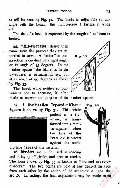
as will be seen by Fig. 32. The blade is adjustable to any
angle with the beam ; the thumb-screw C fastens it when
set.
The size of a bevel is expressed by the length of its beam in
inches.
Fig. 3324. "Miter-Squares" derive their
name from the purpose they are in
tended to serve. A "miter" in con
struction is one-half of a right angle,
or an angle of 45 degrees. In the
" miter-square " the blade, as in the
try-square, is permanently set, but
at an angle of 45 degrees, as shown
by Fig. 33.
The bevel, while neither so con
venient nor so accurate, is often
made to answer the purpose of the "miter-square."
25. A Combination Try-and-" Miter "Square is shown by Fig. 34. This, while
perfect as a try-
square, is trans
formed into a "mi
ter-square " when
the face of the
beam AB is placed
against the work
ing-face (119) of the material.
26. Dividers are much used in spacing
and in laying off circles and arcs of circles.
The form shown by Fig. 35 is known as "arc and set-screw
dividers." The two points are held at any desired distance
from each other by the action of the set-screw A upon the
arc B. In setting, the final adjustment may be made more
Downlo
aded
from
wkFine
Tools
.com

1 6 BENCH WORK IN WOOD.
delicate by use of the thumb-nut C, which, acting in opposi
tion to the spring D, shortens the arc B or allows the spring to
lengthen it, as may be required.
27. Scribing with Dividers: Example 1. —The four legs
of a table are of unequal length, and prevent it from standing
even. Scribe the legs to length.
First, by means of blocks or wedges under the shorter legs,
make the top of the table to stand parallel to some plane sur
face, as a bench top, or even the floor if
it is in good condition, either of which
may be designated as F, Fig. 36. Set
the dividers equal to or greater than the
height of the thickest blocking, so that
while one point, a, touches the leg, the
other, b, will rest upon F in the same vertical line. Move the
dividers, keeping b on F, and producing by a a line on the leg, as
ca, which, if the dividers are properly handled, will be parallel
to the surface F. Without changing the dividers, mark at least
two adjoining faces on each leg, and cut the legs to line.
It is evident that lines thus scribed will all be at an equal
distance from the surface F; and the table top, having been
made parallel to F, it
follows that the lines
scribed are parallel to
the top, or that the
length of the four legs,
as denned by the lines,
is the same.
Example 2. — It is required to fit the end of a board B to
the outline abcd of A, Fig. 37. Place the board in the position
shown, and set the dividers at a distance equal to x. With
one point at a and the other at e, let them be moved together,
one following the outline abcd which the other produces on B,
Downlo
aded
from
wkFine
Tools
.com
BENCH TOOLS. 17
as shown. Cut to line, and the board will fit. When sharp
angles, as at f, enter into the outline, greater accuracy will
be attained if the point / is located by measuring from the
base line hi.
Fig. 38
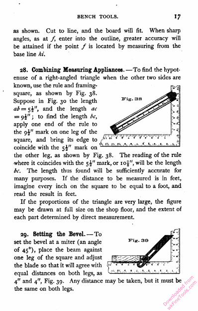
28. Combining Measuring Appliances. —To find the hypot
enuse of a right-angled triangle when the other two sides are
known, use the rule and framing-
square, as shown by Fig. 38.
Suppose in Fig. 30 the length
ab = 5^", and the length ac
= 9^" ; to find the length bc,
apply one end of the rule to
the 9^" mark on one leg of the
square, and bring its edge to /'
coincide with the 5J" mark on
the other leg, as shown by Fig. 38. The reading of the rule
where it coincides with the mark, or 10J", will be the length
bc. The length thus found will be sufficiently accurate for
many purposes. If the distance to be measured is in feet,
imagine every inch on the square to be equal to a foot, and
read the result in feet.
If the proportions of the triangle are very large, the figure
may be drawn at full size on the shop floor, and the extent of
each part determined by direct measurement.
Fig. 39
29. Setting the Bevel. —To
set the bevel at a miter (an angle
of 450), place the beam against
one leg of the square and adjust
the blade so that it will agree with
equal distances on both legs, as
4" and 4", Fig. 39. Any distance may be taken, but it must be
the same on both legs.
Downlo
aded
from
wkFine
Tools
.com

i8 BENCH WORK IN WOOD.
The carpenter frequently describes an angle to which the bevel
may be set as " i in 2 " or " 1 in 4," by which is meant that
while the beam is applied, as shown by Fig. 39, the blade corre
sponds to the 1" mark on one leg, and the 2" mark on the other ;
or to the 1" mark on one leg, and the 4" mark on the other.
30. To set the Bevel at an Angle of 60, and of 120 De-
- In Fig. 40 the board A has a jointed edge a ; at any
Fis. 40 distance from a, gauge aline be. From any point
on be, with any radius,
use the dividers to strike
the arc be ; with same
radius, strike from b the
arc f. Place the beam
of the bevel against face
a, move blade till it co
incides with the points b and /, and the bevel is set at an angle of
60 degrees with one side of beam, and 1 20 degrees with the other.
60 degrees is the measure of the angle between any two faces of
an equilateral triangle, and 120 degrees, of the angle between
any two faces of a regular hexagon ; for these reasons, the bevel
set at these angles is often of use in construction.
31. To set the Bevel at any given Angle. — If an attempt
jrig.4.1 is made to set the bevel di
rectly from lines on paper, it
will be found difficult to de
termine when the tool agrees
with the drawing. It is better
to transfer such an angle to a
board, from the working-edge
of which the bevel may be
set. Thus, if it is required
to set the bevel at the angle
abc, Fig. 41, a board, as A,
should be lined as follows :
from the working-edge gauge the line a'b' ; with the dividers,
Downlo
aded
from
wkFine
Tools
.com
BENCH TOOLS. 19
at any convenient radius, describe from b' the arc e'd!. ; with the
same radius describe from b the arc ed ; set the dividers so that
with one point on e the other will fall onf, and lay off this dis
tance on e'd', locating f ; connect b' and f ; the angle a'b'c'
will be equal to abc. As a'b' is by construction parallel to the
working-edge of the board, the angle between the working-
edge and b'c' is equal to the angle abc. If, then, with the beam
of the bevel on the working-edge, the blade is made to coin
cide with b'c', the bevel will be set at the angle abc.
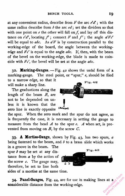
32. Marking-Gauges. — Fig. 42 shows the usiial form of a
marking-gauge. The steel point, or "spur," e, should be filed
to a narrow edge, so that it
will make a sharp line.
The graduations along the
length of the beam B, are
not to be depended on un
less it is known that the
zero line is exactly opposite C£M"*ei)
the spur. When the zero mark and the spur do not agree, as
is frequently the case, it is necessary in setting the gauge to
measure from the head A to the spur e. A when set, is pre
vented from moving on B, by the screw C.
33. A Mortise-Gauge, shown by Fig. 43, has two spurs, a
being fastened to the beam, and b to a brass slide which works
in a groove in the beam. The
spur b may be set at any dis
tance from a by the action of
the screw c. The gauge may,
therefore, be set to line both
sides of a mortise at the same time.
34. Panel-Gauges, Fig. 44, are for use in making lines at a
considerable distance from the working-edge.
Downlo
aded
from
wkFine
Tools
.com

20 BENCH WORK IN WOOD.
The length of the head A is sufficiently increased to receive
good support from the working-edge, which guides it.
35. Cutting-Gauges, having a long, thin blade in the place
of the usual spur, are in form similar to that shown by Fig. 42.
They are" useful in cutting strips of thin material.
36. Chalk-Lines are very seldom used in bench work, but
are often convenient in applying such work to larger structures.
The cord used in lining should be as small as is consistent with
strength. On most surfaces blue chalk is more easily seen than
37. The Scriber, as known to the trade, takes a variety of
forms, from that of an awl to that of a peculiar short-bladed
knife. A well-kept pocket knife of convenient size will be
found a good substitute for any of them.
38. The Pencil used in lining on board surfaces should be
soft, and kept well-pointed by frequent sharpening.
39. Firmer-Chisels have blades wholly of steel. They are
fitted with light handles and are intended for hand use only.
Fig. 45
40. Framing-Chisels have heavy iron blades overlaid with
steel. The handles are stout and are protected at the end by
ferrules. This chisel is used in heavy mortising and framing,
and is driven to its work by the mallet.
white.
Chisels and Chisel-like Tools.
D
Downlo
aded
from
wkFine
Tools
.com
BENCH TOOLS. 2i
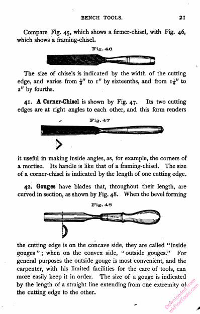
Compare Fig. 45, which shows a firmer-chisel, with Fig. 46,
which shows a framing-chisel.
The size of chisels is indicated by the width of the cutting
edge, and varies from to 1" by sixteenths, and from i\" to
2" by fourths.
41. A Corner-Chisel is shown by Fig. 47. Its two cutting
edges are at right angles to each other, and this form renders
, ITig. 47-
>
it useful in making inside angles, as, for example, the corners of
a mortise. Its handle is like that of a framing-chisel. The size
of a corner-chisel is indicated by the length of one cutting edge.
42. Gouges have blades that, throughout their length, are
curved in section, as shown by Fig. 48. When the bevel forming
ITig. 48
the cutting edge is on the concave side, they are called "inside
gouges " ; when on the convex side, " outside gouges." For
general purposes the outside gouge is most convenient, and the
carpenter, with his limited facilities for the care of tools, can
more easily keep it in order. The size of a gouge is indicated
by the length of a straight line extending from one extremity of
the cutting edge to the other.
Downlo
aded
from
wkFine
Tools
.com

22 BENCH WORK IN WOOD.
43. Handles for chisels, gouges, and similar tools, are of two
general classes, light and heavy ; the former are intended prin
cipally for hand use, and are shown in connection with the firmer-
chisel and gouge ; the latter, which are re-enforced at the end
by a ferrule that they may withstand blows from the mallet, are
illustrated in connection with the framing-chisel and the corner-
chisel.
Handles may be shank-fitted, like the one shown by Fig. 48,
or socket-fitted, as shown by Fig. 47. The better class of tools
have socket-fitted handles.
44. The Drawing-Knife, shown by Fig. 49, is in reality a
wide chisel, though it is quite different from a chisel in form.
Fig. 49
The handles are so attached as to stand in advance of the cut
ting edge, which is drawn into the work, instead of being pushed
into it, as is the case with a chisel. The drawing-knife is very
effective on narrow surfaces that are to be considerably reduced.
The size is indicated by the length of the cutting edge.
45. The Action of Cutting Wedges. — Every cutting tool
is a wedge more or less acute. In action it has two operations
to perform : first, cutting the fibers of the wood ; and, secondly,
widening the cut in order that the tool may penetrate into the
material, and thus allow the cutting edge to go on with its
work. To widen the cut, the fibers of the wood must be pressed
apart (the wood split), or the fiber ends crushed, or the mate
rial on one side of the wedge must be bent, thus forming a
Downlo
aded
from
wkFine
Tools
.com
BENCH TOOLS. 23
shaving. It is evident that a unit of force tending to drive the
edge forward will, under like conditions of material, always
result in the same amount of incision. But much less force is
required to carry the tool forward when the cutting edge is just
entering the material, than when it has advanced to a consider
able depth, and, hence, it is fair to assume that this difference is
due solely to the resistance that the material offers in opening
to make way for the tool, this resistance increasing as the tool
goes deeper. The resistance offered to a tool by a bending
shaving, therefore, may be many times greater than that offered
to the cutting edge by the wood fibers.
An obtuse-angled wedge will cut as easily as a more acute-
angled one, but the more obtuse the angle is, the more abrupt
must be the turning of the shaving ; and since the latter factor
is the more important, as regards the absorption of force, it
follows that the more acute the cutting edge is, the more easily
it will accomplish its work.
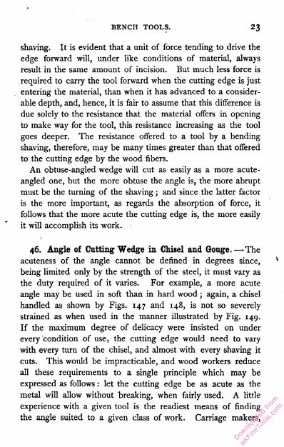
46. Angle of Cutting Wedge in Chisel and Gouge. —-The
acuteness of the angle cannot be defined in degrees since,
being limited only by the strength of the steel, it must vary as
the duty required of it varies. For example, a more acute
angle may be used in soft than in hard wood ; again, a chisel
handled as shown by Figs. 147 and 148, is not so severely
strained as when used in the manner illustrated by Fig. 149.
If the maximum degree of delicacy were insisted on under
every condition of use, the cutting edge would need to vary
with every turn of the chisel, and almost with every shaving it
cuts. This would be impracticable, and wood workers reduce
all these requirements to a single principle which may be
expressed as follows : let the cutting edge be as acute as the
metal will allow without breaking, when fairly used. A little
experience with a given tool is the readiest means of finding
the angle suited to a given class of work. Carriage makers,
Downlo
aded
from
wkFine
Tools
.com
24 BENCH WORK IN WOOD.
*
who work almost wholly in hard woods, are in the habit of
using what pattern makers, who work principally in soft woods,
would style blunt chisels.
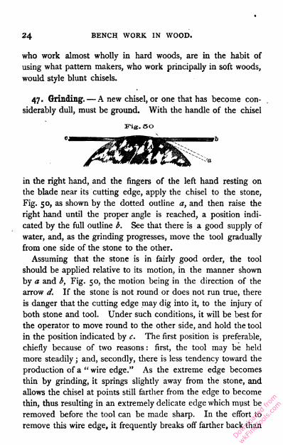
47. Grinding. —A new chisel, or one that has become con
siderably dull, must be ground. With the handle of the chisel
in the right hand, and the fingers of the left hand resting on
the blade near its cutting edge, apply the chisel to the stone,
Fig. 50, as shown by the dotted outline a, and then raise the
right hand until the proper angle is reached, a position indi
cated by the full outline b. See that there is a good supply of
water, and, as the grinding progresses, move the tool gradually
from one side of the stone to the other.
Assuming that the stone is in fairly good order, the tool
should be applied relative to its motion, in the manner shown
by a and b, Fig. 50, the motion being in the direction of the
arrow d. If the stone is not round or does not run true, there
is danger that the cutting edge may dig into it, to the injury of
both stone and tool. Under such conditions, it will be best for
the operator to move round to the other side, and hold the tool
in the position indicated by c. The first position is preferable,
chiefly because of two reasons : first, the tool may be held
more steadily ; and, secondly, there is less tendency toward the
production of a " wire edge." As the extreme edge becomes
thin by grinding, it springs slightly away from the stone, and
allows the chisel at points still farther from the edge to become
thin, thus resulting in an extremely delicate edge which must be
removed before the tool can be made sharp. In the effort to
remove this wire edge, it frequently breaks off farther back than
Fig. so
e,
*
Downlo
aded
from
wkFine
Tools
.com

BENCH TOOLS. 25
is desired, and the process of whetting is prolonged. With the
chisel held at c (instead of b, the proper position) the direc
tion of the motion relative to the tool aggravates this tendency
of the light edge to spring away from the stone.
The grinding process is complete when the ground surface
reaches the cutting edge — a condition readily determined by
holding the tool to the light. If it is still dull, there will be a
bright line along the cutting edge. When this line has disap
peared, the tool is as sharp as it can be made by grinding,
which, if persisted in, will only result in a wire edge. The
action of the grindstone, however, is too severe to produce a
good cutting edge, and the chisel, after being ground, must be
whetted (107 -no).
48. To whet the
chisel, apply it to t. ...... 1the oilstone A, Fig.
51, in the position
shown by the dot
ted outline b, and
as it is moved back
and forth along the length of the stone, as indicated by the
arrows, gradually bring it to the position shown by b'. That is,
the angle between it and the stone is to be increased until the
cutting edge c comes in contact with the stone ; this position
can be recognized by the sensation imparted to the hand, and
the behavior of the oil with which the stone is lubricated. At
first thought, it may seem that
the bevel ab, Fig. 52, which was
produced by the grinding, should
be maintained in whetting; but
to do this would require so much
time that one corresponding very
nearly to ab, as cd, is taken.Great care is necessary on the part of one unskilled to avoid giv-
Downlo
aded
from
wkFine
Tools
.com

26 BENCH WORK IN WOOD.
ing the tool a rocking motion on the oilstone ; if this is indulged
Fia. 53 m, t^le ectee "vvill appear rounded, as
shown by Fig. 53, and will be no
sharper than if it had the form
indicated by the dotted outline
abc. When sufficiently whetted, the cutting edge, if held to
the light, will show a dull, grayish hue. If a bright line appears
along the edge, it is not yet sharp. The whetting turns a light
wire edge over on the flat face, an exaggeration of which is
shown by a, Fig. 54. This can
not always be seen, but may be
detected by the finger ; it is re
moved by a single stroke of the
blade with the flat face on the
stone, as shown by a', Fig. 51. It is necessary, however, that
every precaution be taken to prevent the production of a bevel
indicated by the dotted line c, Fig. 54, and opposite that
already existing. To guard against this, the chisel should be
applied to the stone in the manner illustrated by the outline a,
Fig- 51 ("i-"5)-
A tool must be whetted often enough to keep the edge in
good condition ; it is dull whenever it fails to cut well. When,
by frequent whetting, the whetted surface becomes so broad as
to require considerable time in the production of the edge, it
should be reground, and the process just described repeated.
This method of sharpening the chisel will, in general, apply
to the gouge, drawing-knife, and all similar tools.
Saws.49. The efficiency of any saw is measured by the amount of
force it absorbs in making a given cut or " kerf." For example,
if one saw severs a 4" X 4" timber with half the force required
by another, it is evident that the second saw is only one-half
as efficient as the first. Almost every element that enters into
Downlo
aded
from
wkFine
Tools
.com

BENCH TOOLS. 27
saw construction has its effect on the efficiency of the tool.
Chief among them is the thickness of the blade, which, of
.course, determines the width of the kerf ; for a wide kerf will
require the removal of more material than a narrow one, and
the force absorbed in each case must bear some relation to the
amount of material removed. In recognition of this fact, the
people of some eastern countries use saws designed to cut
when drawn towards the operator, a method of handling that
allows great thinness of blade — too great to stand the thrust by
which our saws are driven into the work. But the result is
that the Chinese saw, for example, Fig. ss
which is represented by Fig. 55,
accomplishes its work with re
markable ease. The shape of such a saw, however, and the
awkward manner of applying force to it, probably more than
neutralize the advantage gained from its delicacy, although in
the abstract, the thinner the blade the better the saw.
50. The form of our own saws is not the result of chance,
but, on the contrary, has been developed after a careful study
of the conditions under which they are required to work.
Other things being equal, pushing a saw gives better results
than pulling it. Under a thrusting force, it is found necessary
to make the blade sufficiently thick and strong to resist bend
ing tendencies, but with no surplus material to add unneces
sary weight. In view of these facts the outline of the blade is
tapered, as shown by Fig. 56. The blade is thicker also at the
handle than at the point. To assist in giving it clearance in
the kerf, it is tapered from the teeth to the back. This differ
ence in thickness is accomplished in the process of manufacture,
Downlo
aded
from
wkFine
Tools
.com
28 BENCH WORK IN WOOD.
by grinding the rough blade after it has been hardened. Im
perfections left by the hardening or the grinding process, may
be detected in the finished saw by bending the blade, as shown
by Fig. 57. If it is uniformly ground and hardened, the curve
will be regular as shown ; if it is thick in spots, or if it varies in
hardness, the curve will be uneven, as indicated by the dotted
line.
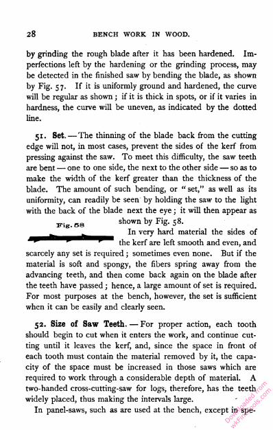
51. Set. —The thinning of the blade back from the cutting
edge will not, in most cases, prevent the sides of the kerf from
pressing against the saw. To meet this difficulty, the saw teeth
are bent— one to one side, the next to the other side — so as to
make the width of the kerf greater than the thickness of the
blade. The amount of such bending, or " set," as well as its
uniformity, can readily be seen by holding the saw to the light
with the back of the blade next the eye ; it will then appear as
yig.ss shown by Fig. 58.
v ^ In very hard material the sides of
- ~ "~ the kerf are left smooth and even, andscarcely any set is required ; sometimes even none. But if the
material is soft and spongy, the fibers spring away from the
advancing teeth, and then come back again on the blade after
the teeth have passed ; hence, a large amount of set is required.
For most purposes at the bench, however, the set is sufficient
when it can be easily and clearly seen.
52. Size of Saw Teeth. — For proper action, each tooth
should begin to cut when it enters the work, and continue cut
ting until it leaves the kerf, and, since the space in front of
each tooth must contain the material removed by it, the capa
city of the space must be increased in those saws which are
required to work through a considerable depth of material. A
two-handed cross-cutting-saw for logs, therefore, has the teeth
widely placed, thus making the intervals large.
In panel-saws, such as are used at the bench, except in spe
Downlo
aded
from
wkFine
Tools
.com
BENCH TOOLS. 29
cial cases, the space is of the same size and form with the
tooth. When the spaces are large, the teeth must be large,
and, since the size of the spaces has a direct relation to the
amount of material removed, it may be said that the size of
the teeth depends on the size of the material in which the saw
is to work.
The size of saw teeth is expressed by the number contained
in an inch. Thus " 6 teeth " means that the distance from
one point to another is £ ".
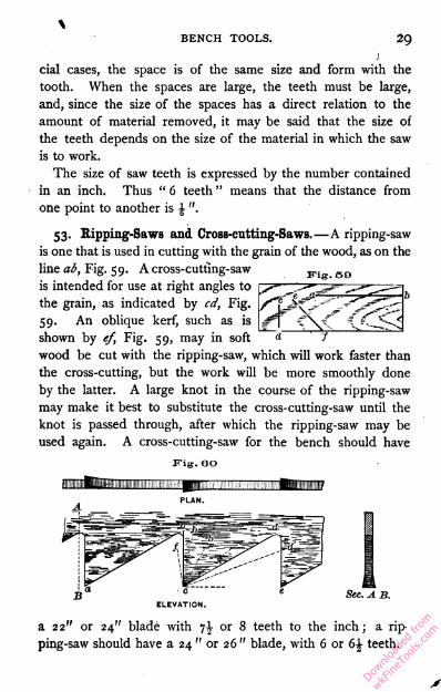
53. Ripping-Saws and Cross-cutting-Saws.—A ripping-saw
is one that is used in cutting with the grain of the wood, as on the
line ab, Fig. 59. A cross-cutting-saw
is intended for use at right angles to
the grain, as indicated by cd, Fig.
59. An oblique kerf, such as is
shown by ef, Fig. 59, may in soft
wood be cut with the ripping-saw, which will work faster than
the cross-cutting, but the work will be more smoothly done
by the latter. A large knot in the course of the ripping-saw
may make it best to substitute the cross-cutting-saw until the
knot is passed through, after which the ripping-saw may be
used again. A cross-cutting-saw for the bench should have
p"ig. eo
Fig. so
PLAN.A.
Sec. A B.
a 22" or 24" blade with i\ or 8 teeth to the inch; a rip
ping-saw should have a 24 " or 26 " blade, with 6 or d\ teeth.
Downlo
aded
from
wkFine
Tools
.com
30 BENCH WORK IN WOOD.
54. The Teeth of Eipping-Saws. — Fig. 60 shows a plan,
elevation, and section of three teeth as they are usually made
for a ripping-saw. The following paragraphs present a consid
eration of the action of an individual tooth.
All wood is fibrous, and any tool which is to produce a cut
along the length of the fibers, as the saw kerf ab, Fig. 59, roust-
at each period of action, take something from the ends of such
fibers as may lie in the path of the proposed opening. In fulfil
ling this condition, the action of a ripping-saw's tooth is not
unlike the action of a chisel when used as shown by Fig. 149.
Each tooth in its turn removes its share from the fiber ends over
which it passes, just as the chisel at every change of position
takes its slice and lengthens the cut. The cutting edge of
a saw tooth, however, is bounded by a more obtuse angle than
that of a chisel, and as a cutting tool is inferior. Thus, if one
of the three teeth shown by Fig. 60 is applied to a saw kerf in
the position it would occupy as part of a complete saw, it will
appear as represented by Fig. 61, its motion being in the direc
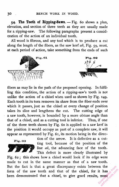
tion of the arrow. It is defective as a cut
ting tool, because of the position of the
line ab, the advancing face of the tooth.
This defect is more clearly illustrated by
Fig. 62 ; this shows how a chisel would look if its edge were
made to cut in the same manner as that of a saw tooth.
But the fact is that a great discrepancy exists between the
form of the saw tooth and that of the chisel, for it has
been demonstrated that a chisel, to give good results, must
Downlo
aded
from
wkFine
Tools
.com
BENCH TOOLS. 31
be at least as acute as is indicated by the dotted line a ;
and it would seem that the former might be improved by
bringing it more nearly to the outline of the latter. Sup
pose this be attempted, and that the face of the tooth in
dicated by the line cb, Fig. 60, be changed to cb'. Such
a change must result either in removing material from the
tooth, and thereby weakening it, or in changing the line cd
to a position cd' . In other words, if the tooth is not weak
ened, the space between it and the next will be reduced.
Again, if to make the advancing face still more acute, the line
cb" is accepted, and the tooth is not made smaller (that is,
weakened), there will be no space between it and the next
tooth. Having no spaces, there can be no teeth, and conse
quently the attempted change is impossible. It will thus be
seen that the angle of the advancing face of the ripping-saw
tooth cannot, unless it is weakened, be much more acute than
is shown by Fig. 60 and Fig. 61.
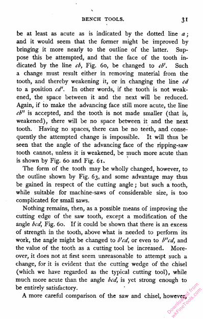
The form of the tooth may be wholly changed, however, to
the outline shown by Fig. 63, and some advantage may thus
be gained in respect of the cutting angle ; but such a tooth,
while suitable for machine-saws of considerable size, is too
complicated for small saws.
Nothing remains, then, as a possible means of improving the
cutting edge of the saw tooth, except a modification of the
angle bcd, Fig. 60. If it could be shown that there is an excess
of strength in the tooth, above what is needed to perform its
work, the angle might be changed to b'cd, or even to b"cd, and
the value of the tooth as a cutting tool be increased. More
over, it does not at first seem unreasonable to attempt such a
change, for it is evident that the cutting wedge of the chisel
(which we have regarded as the typical cutting tool), while
much more acute than the angle bcd, is yet strong enough to
be entirely satisfactory.
A more careful comparison of the saw and chisel, however,
Downlo
aded
from
wkFine
Tools
.com
32 BENCH WORK IN WOOD.
discloses the following facts : first, a saw tooth must be softer
than a chisel in order that it may be set and filed, and being
softer, is therefore weaker in its substance ; secondly, the width
of the saw tooth is less than half the width of the narrowest
chisel made, and, in this respect also, it is at a disadvan
tage ; and, thirdly, in using a chisel the operator's atten
tion is given entirely to its one cutting edge, and if at any
time it is Jikely to receive too much strain, it is at once re
lieved ; while each saw tooth, on the contrary, forms but a
small part of a tool that receives little attention and much vig
orous handling while it is being driyen through straight grain,
crooked grain, or hard knots, as the case may be. From a
consideration of these points, it seems clear that the cutting-
angle of a saw tooth must be less acute than that of a chisel.
But the degree of acuteness can be determined only by use.
Fig. 60 shows the form which years of experience have proved
the most practicable for general work, and while some bench-
workers do file their saws " under," producing a tooth similar
to dcb', as many more go to the other extreme and use a tooth
similar to dcf. The typical form given is easily kept in order,
and, when in that condition, will cut freely and well.
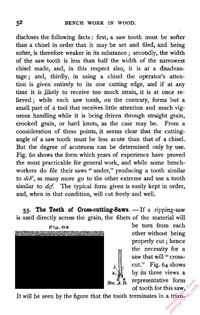
Fig. 6455. The Teeth of Cross-eutting-Saws. — If a ripping-saw
is used directly across the grain, the fibers of the material will
be torn from each
other without being
properly cut ; hence
the necessity for a
saw that will " cross
cut." Fig. 64 shows
by its three views a
representative form
of tooth for this saw.
It will be seen by the figure that the tooth terminates in a trian
Downlo
aded
from
wkFine
Tools
.com
BENCH TOOLS. 33
gular point ; and also, that while the point a is formed on one
side of the blade, the next, a', is formed on the opposite side ;
thus throughout its length, the points of any two adjacent teeth
being on opposite sides of the blade. This arrangement makes
the end view of the blade show two parallel lines of points, and
between them a triangular depression, which, when exaggerated
by the "set," will appear as shown by
section AB, Fig. 64.
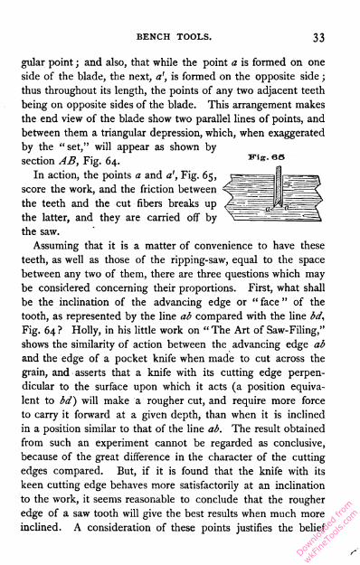
In action, the points a and a', Fig. 65,
score the work, and the friction between
the teeth and the cut fibers breaks up
the latter, and they are carried off by
the saw.
Assuming that it is a matter of convenience to have these
teeth, as well as those of the ripping-saw, equal to the space
between any two of them, there are three questions which may
be considered concerning their proportions. First, what shall
be the inclination of the advancing edge or " face " of the
tooth, as represented by the line ab compared with the line bd,
Fig. 64 ? Holly, in his little work on " The Art of Saw-Filing,"
shows the similarity of action between the advancing edge ab
and the edge of a pocket knife when made to cut across the
grain, and asserts that a knife with its cutting edge perpen
dicular to the surface upon which it acts (a position equiva
lent to bd) will make a rougher cut, and require more force
to carry it forward at a given depth, than when it is inclined
in a position similar to that of the line ab. The result obtained
from such an experiment cannot be regarded as conclusive,
because of the great difference in the character of the cutting
edges compared. But, if it is found that the knife with its
keen cutting edge behaves more satisfactorily at an inclination
to the work, it seems reasonable to conclude that the rougher
edge of a saw tooth will give the best results when much more
inclined. A consideration of these points justifies the belief
Downlo
aded
from
wkFine
Tools
.com
34 BENCH WORK IN WOOD.
that an angle of 60 degrees with the work, that is, with a line
passing through the points a ' and a, is none too great, and all
practice goes to show that teeth so formed not only do very
smooth work, but cut with ease and rapidity.
Secondly, what shall be the angle of the advancing face of
the tooth, as represented by lines e'e and ef, Sec. EF, Fig. 64 ?
Since this angle forms the cutting wedge of the tooth, it should
be as acute as is consistent with strength. Greater strength
being required for action in hard wood than in soft, it follows
that this angle should be varied with the material in which it is
used. For general work it may correspond to the angle e'ef.
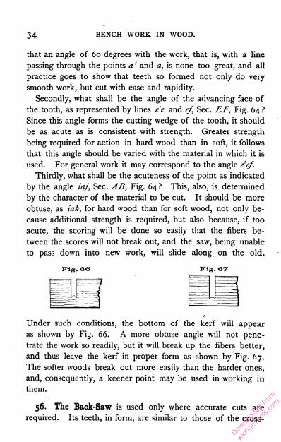
Thirdly, what shall be the acuteness of the point as indicated
by the angle iaj, Sec. AB, Fig. 64? This, also, is determined
by the character of the material to be cut. It should be more
obtuse, as iak, for hard wood than for soft wood, not only be
cause additional strength is required, but also because, if too
acute, the scoring will be done so easily that the fibers be
tween- the scores will not break out, and the saw, being unable
to pass down into new work, will slide along on the old.
Fig. or
nm
Under such conditions, the bottom of the kerf will appear
as shown by Fig. 66. A more obtuse angle will not pene
trate the work so readily, but it will break up the fibers better,
and thus leave the kerf in proper form as shown by Fig. 67.
The softer woods break out more easily than the harder ones,
and, consequently, a keener point may be used in working in
them.
56. The Back-Saw is used only where accurate cuts are
required. Its teeth, in form, are similar to those of the CrOSS-
FiK. GO
Downlo
aded
from
wkFine
Tools
.com

BENCH TOOLS.35
Fig. 68
cutting-saw, except that the line of the advancing face is
brought forward as indicated by bkl, Fig. 64, to increase their
efficiency when used with the
grain. They are, however,
much finer, there being usually
as many as sixteen to the
inch. This saw cuts slowly ascompared with a panel-saw, but may be used in very delicate
work. It is used to cut in any direction relative to the grain
of the wood. The bur left by the file after sharpening, forms
a sufficient set.
The blade A, Fig. 68, is in itself too thin to withstand the
thrust necessary to drive it into the work, and is strengthened
by an iron "back," B. This, being thicker than the blade, will
not allow the saw to penetrate beyond a depth represented by
the distance C. For this reason the blade is uniform in width
instead of tapering.
Sec. AB(Enlarged)
57. The Compass-Saw, shown by Fig. 69, is intended forsawing in curved lines. Its blade is extremely thick, and the
v teeth are given an enor-Fig. 00 0
mous amount of set. Seesections AB and CD,Fig. 69. If the curve inwhich it is to be used isvery small, only a shortportion of the blade'slength next the point canbe used. With a curveof longer radius, a greater length of blade may be brought intoaction.
Its teeth are of the form shown by Fig. {lw.
70, having the square face of the ripping-
saw, and the point of the cross-cutting-saw.
Fig. vo
Downlo
aded
from
wkFine
Tools
.com
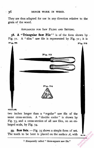
36 BENCH WORK IN WOOD.
They are thus adapted for use in any direction relative to the
grain of the wood.
Appliances for Saw Filing and Setting.
58. A "Triangular Saw File"1 is of the form shown by
Fig. 71. A "slim" saw file is represented by Fig. 72; it is
i
Fig. 73
REGULAR.
two inches longer than a "regular" saw file of the
same cross-section. A " double ender " is shown by
Fig. 73, and a cross-section of all saw files, on an en
larged scale, by Fig. 74.
59. Saw Sets. — Fig. 75 shows a simple form of set.
The tooth to be bent is placed on the surface A, with
1 Frequently called " three-square saw file."
Downlo
aded
from
wkFine
Tools
.com
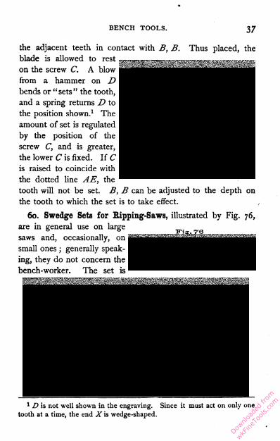
BENCH TOOLS.37
the adjacent teeth in contact with B, B. Thus placed, theblade is allowed to rest
on the screw C. A blow
from a hammer on D
bends or "sets" the tooth,
and a spring returns D to
the position shown.1 The
amount of set is regulated
by the position of the
screw C, and is greater,
the lower C is fixed. If C
is raised to coincide with
the dotted line AE, the
tooth will not be set. B, B can be adjusted to the depth on
the tooth to which the set is to take effect.
60. Swedge Sets for Ripping-Saws, illustrated by Fig. 76,
are in general use on large
saws and, occasionally, on
small ones ; generally speak
ing, they do not concern the
bench-worker. The set is
vis. re
1 D is not well shown in the engraving. Since it must act on only one
tooth at a time, the end X is wedge-shaped.
Downlo
aded
from
wkFine
Tools
.com
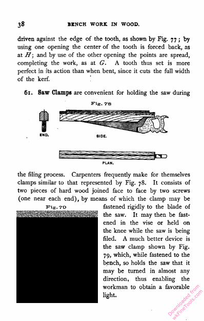
38 BENCH WORK IN WOOD.
driven against the edge of the tooth, as shown by Fig. 77 ; by
using one opening the center of the tooth is forced back, as
at H ; and by use of the other opening the points are spread,
completing the work, as at G. A tooth thus set is more
perfect in its action than when bent, since it cuts the full width
of the kerf.
61. Saw Clamps are convenient for holding the saw during
Fig. 78
Fig. 79
the filing process. Carpenters frequently make for themselves
clamps similar to that represented by Fig. 78. It consists of
two pieces of hard wood joined face to face by two screws
(one near each end), by means of which the clamp may be
fastened rigidly to the blade of
the saw. It may then be fast
ened in the vise or held on
the knee while the saw is being
filed. A much better device is
the saw clamp shown by Fig.
79, which, while fastened to the
bench, so holds the saw that it
may be turned in almost any
direction, thus enabling the
workman to obtain a favorable
Downlo
aded
from
wkFine
Tools
.com
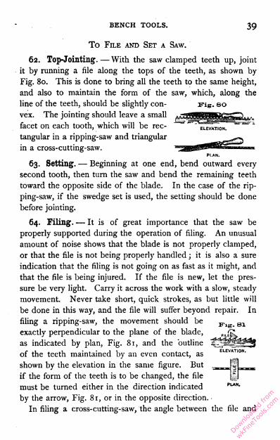
BENCH TOOLS.39
To File and Set a Saw.
62. Top-Jointing. — With the saw clamped teeth up, joint
it by running a file along the tops of the teeth, as shown by
Fig. 80. This is done to bring all the teeth to the same height,
and also to maintain the form of the saw, which, along the
line of the teeth, should be slightly con
vex. The jointing should leave a small
facet on each tooth, which will be rec
tangular in a ripping-saw and triangular
in a cross-cutting-saw.
PLAN.
63. Setting. — Beginning at one end, bend outward every
second tooth, then turn the saw and bend the remaining teeth
toward the opposite side of the blade. In the case of the rip
ping-saw, if the swedge set is used, the setting should be done
before jointing.
64. Filing. — It is of great importance that the saw be
properly supported during the operation of filing. An unusual
amount of noise shows that the blade is not properly clamped,
or that the file is not being properly handled ; it is also a sure
indication that the filing is not going on as fast as it might, and
that the file is being injured. If the file is new, let the pres
sure be very light. Carry it across the work with a slow, steady
movement. Never take short, quick strokes, as but little will
be done in this way, and the file will suffer beyond repair. In
filing a ripping-saw, the movement should be
exactly perpendicular to the plane of the blade,
as indicated by plan, Fig. 81, and the outline
of the teeth maintained by an even contact, as
shown by the elevation in the same figure. But
if the form of the teeth is to be changed, the file
must be turned either in the direction indicated PLAN-
by the arrow, Fig. 81, or in the opposite direction. ■
In filing a cross-cutting-saw, the angle between the file and
Downlo
aded
from
wkFine
Tools
.com

40 BENCH WORK IN WOOD.
the blade must be varied in accordance with the following con
siderations : first, the outline of the teeth may be preserved
or changed in the manner just described in connection with
the ripping-saw ; secondly, the angle of the advancing face
(e'ef, Fig. 64) is determined by the inclination of the file
upon from principles already given, it may be produced without
difficulty by attending to the foregoing directions.
In filing any- of the teeth .herein discussed, the file should
always be in gentle contact with the face of one tooth, as b,
Fig. 81, while most of the cutting is done on the back of the
next one a, which, as usually considered, is the tooth that is
being filed. This tooth should be one which, by its set, bends
away from the operator. Beginning at one end of the blade,
he files every second tooth until the opposite end is reached,
when the blade is turned, and the remaining teeth filed from
the other side.
No saw, even though the teeth are not bent, should be filed
wholly from one side, for the file turns a slight edge, or bur ;
and, since this increases the set, it should be evenly distributed
on both sides of the blade.
The filing on each tooth should continue until the facet
produced by the jointing disappears. After this is accom
plished, a single stroke will make the tooth receiving it lower
than the others. To avoid this, it will be found best to leave
BIDE ELEVATION.END ELEVATION.
to the blade, as shown
by the plan, Fig. 82 ;
thirdly, the angle of the
point (iaj, Fig. 64) is
determined by the incli
nation of the file to the
blade, as shown by the
end elevation, Fig. 82.
The form of the teeth
having been decided
Downlo
aded
from
wkFine
Tools
.com
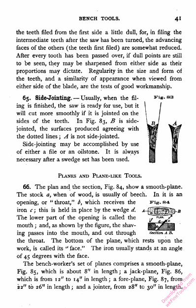
BENCH TOOLS. 41
the teeth filed from the first side a little dull, for, in filing the
intermediate teeth after the saw has been turned, the advancing
faces of the others (the teeth first filed) are somewhat reduced.
After every tooth has been passed over, if dull points are still
to be seen, they may be sharpened from either side as their
proportions may dictate. Regularity in the size and form of
the teeth, and a similarity of appearance when viewed from
either side of the blade, are the tests of good workmanship.
65. Side-Jointing. — Usually, when the fil- Fig. 83ing is finished, the saw is ready for use, but it
will cut more smoothly if it is jointed on the
sides of the teeth. In Fig. 83, B is side-
jointed, the surfaces produced agreeing with
the dotted lines ; A is not side-jointed.
Side-jointing may be accomplished by use
of either a file or an oilstone. It is always
necessary after a swedge set has been used.
Planes and Plane-like Tools.
66. The plan and the section, Fig. 84, show a smooth-plane.
The stock a, when of wood, is usually of beech. In it is an
opening, or " throat," b, which receives the Fig. 84
iron c ; this is held in place by the wedge d.
The lower part of the opening is called the
mouth ; and, as shown by the figure, the shav
ing passes into the mouth, and out through section a b.
the throat. The bottom of the plane, which rests upon the
work, is called its " face." The iron usually stands at an angle
of 45 degrees with the face.
The bench-worker's set of planes comprises a smooth-plane,
Fig. 85, which is about 8" in length; a jack-plane, Fig. 86,
which is from 12" to 14'.' in length; a fore-plane, Fig. 87, from
22" to 26" in length ; and a jointer, from 28" to 30" in length.
Downlo
aded
from
wkFine
Tools
.com

43 BENCH WORK IN WOOD.
Similar purposes are served by the jointer and the fore-plane,
the former being unnecessary except for large surfaces that are
to be planed with accuracy.
Fig. 85 Fig. 8767. The Length of the Plane-Stock determines, in a measure,
the straightness of the work. Thus, a smooth-plane, if used on
Fig. 88 an uneven surface, will,
as shown by Fig. 88, rise
over elevated portions and
settle in hollows, taking its shaving without interruption, and
producing no great change in the outline of the surface, while
a fore -plane or jointer
similarly applied will, as
shown by Fig. 89, cut
only on the higher parts,
and by so doing, produce an even surface.
The stock of a smooth-plane is made short so that, by its use,
a surface may be smoothed without incurring the necessity of
straightening it.
The fore-plane will smooth as well as the smooth-plane, but
not until it has first straightened the surface.
The jack-plane is used for cutting heavy shavings, and its
length bears no relation to the character of the work expected
of it, but is such as will enable the workman to grasp it easily
and firmly.
68. A "Plane-Iron"1 for a wooden plane is of iron overlaid
in part with steel. Its cutting edge is maintained in precisely
the same way as that of a chisel. See 47 and 48. The angle
1 Known also as " plane-bit."
Downlo
aded
from
wkFine
Tools
.com
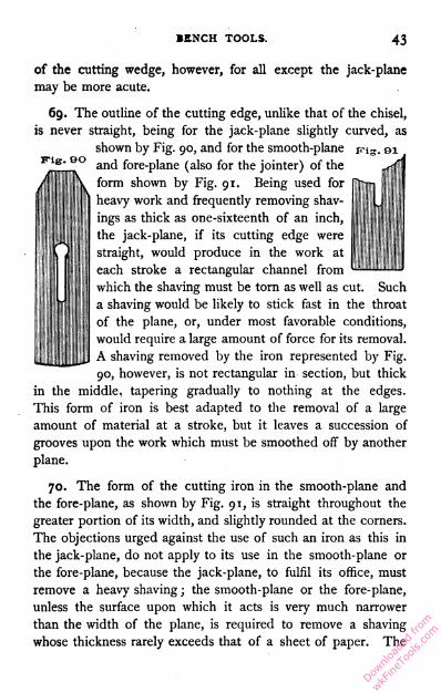
BENCH TOOLS. 43
Fig. GO
of the cutting wedge, however, for all except the jack-plane
may be more acute.
69. The outline of the cutting edge, unlike that of the chisel,
is never straight, being for the jack-plane slightly curved, asshown by Fig. 90, and for the smooth-plane tns. ei
and fore-plane (also for the jointer) of the
form shown by Fig. 91. Being used for
heavy work and frequently removing shav
ings as thick as one-sixteenth of an inch,
the jack-plane, if its cutting edge were
straight, would produce in the work at
each stroke a rectangular channel from
which the shaving must be torn as well as cut. Such
a shaving would be likely to stick fast in the throat
of the plane, or, under most favorable conditions,
would require a large amount of force for its removal.
A shaving removed by the iron represented by Fig.
90, however, is not rectangular in section, but thick
in the middle, tapering gradually to nothing at the edges.
This form of iron is best adapted to the removal of a large
amount of material at a stroke, but it leaves a succession of
grooves upon the work which must be smoothed off by another
plane.
70. The form of the cutting iron in the smooth-plane and
the fore-plane, as shown by Fig. 91, is straight throughout the
greater portion of its width, and slightly rounded at the corners.
The objections urged against the use of such an iron as this in
the jack-plane, do not apply to its use in the smooth-plane or
the fore-plane, because the jack-plane, to fulfil its office, must
remove a heavy shaving ; the smooth-plane or the fore-plane,
unless the surface upon which it acts is very much narrower
than the width of the plane, is required to remove a shaving
whose thickness rarely exceeds that of a sheet of paper. The
Downlo
aded
from
wkFine
Tools
.com
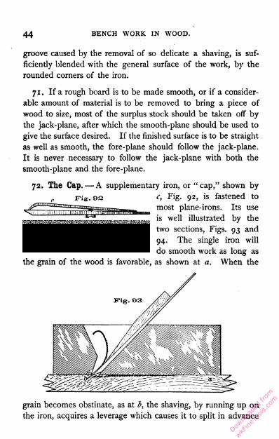
44 BENCH WORK IN WOOD.
groove caused by the removal of so delicate a shaving, is suf
ficiently blended with the general surface of the work, by the
rounded corners of the iron.
7.X. If a rough board is to be made smooth, or if a consider
able amount of material is to be removed to bring a piece of
wood to size, most of the surplus stock should be taken off by
the jack-plane, after which the smooth-plane should be used to
give the surface desired. If the finished surface is to be straight
as well as smooth, the fore-plane should follow the jack-plane.
It is never necessary to follow the jack-plane with both the
smooth-plane and the fore-plane.
72. The Cap.- A supplementary iron, or " cap," shown by
)2 c, Fig. 92, is fastened to
most plane-irons. Its use
is well illustrated by the
two sections, Figs. 93 and
94. The single iron will
do smooth work as long as
the grain of the wood is favorable, as shown at a. When the
grain becomes obstinate, as at b, the shaving, by running up on
the iron, acquires a leverage which causes it to split in advance
Downlo
aded
from
wkFine
Tools
.com
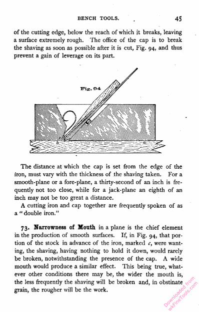
BENCH TOOLS. 45
of the cutting edge, below the reach of which it breaks, leaving
a surface extremely rough. The office of the cap is to break
the shaving as soon as possible after it is cut, Fig. 94, and thus
prevent a gain of leverage on its part.
The distance at which the cap is set from the edge of the
iron, must vary with the thickness of the shaving taken. For a
smooth-plane or a fore-plane, a thirty-second of an inch is fre
quently not too close, while for a jack-plane an eighth of an
inch may not be too great a distance.
A cutting iron and cap together are frequently spoken of as
a " double iron."
73. Narrowness of Month in a plane is the chief element
in the production of smooth surfaces. If, in Fig. 94, that por
tion of the stock in advance of the iron, marked c, were want
ing, the shaving, having nothing to hold it down, would rarely
be broken, notwithstanding the presence of the cap. A wide
mouth would produce a similar effect. This being true, what
ever other conditions there may be, the wider the mouth is,
the less frequently the shaving will be broken and, in obstinate
grain, the rougher will be the work.
Downlo
aded
from
wkFine
Tools
.com
46 BENCH WORK IN WOOD.
74. To Adjust the Iron. — To set the iron deeper, so that
a heavier cut may be taken, strike it a light blow, as indicated
by the arrow e, Fig. 84. If a lighter cut is required, strike the
stock as indicated by the arrow f. When the iron is in the
right position, a light blow will tighten the wedge. To remove
the iron and wedge, turn the plane over so that the face is
uppermost, grasp the iron and wedge with the right hand, hold
the back end of the plane between the thumb and finger of the
left, and strike the stock at / upon the surface of the bench.
A single blow is usually sufficient.
Never strike the plane while it is resting on the bench or any
support that is firm. It should be held in the hand clear of
everything ; but, if this is not convenient, one end may rest on
the knee.
To set the iron in a wooden plane, hold the stock in such a
way that, while the face rests on the hand, the end of the fore
finger may extend across the mouth. Put the iron in place,
allowing its cutting edge to rest on the forefinger, which should
keep it from projecting. Insert the wedge, push it down with
the thumb, and by a light blow with the hammer drive the iron
down until its projection beyond the level of the face is equal
to the thickness of the shaving that the plane is to take ; a sin
gle tap on the wedge will then tighten the iron in place. The
distance that the iron projects, can easily be determined by
sighting along the face of the plane.
The wedge must not be driven too hard, for a plane may be
so distorted by a hard-driven wedge as to make it incapable of
doing good work. The iron will be held in place even when
the wedge is so loose that it may be drawn out with the fingers.
Notwithstanding the fact that wooden plane-stocks are made
from material little affected by atmospheric influences, they
will warp enough, especially when nearly new, to bring the face
considerably out of a true plane. When, from this cause, the
plane fails to do good work, it must be jointed.
Downlo
aded
from
wkFine
Tools
.com
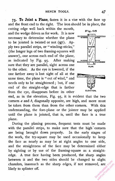
BENCH TOOLS. 47
Fig. 95
manWINDING W / STICK ^
V / -
vf // 1
C,r / 1
WINDING STICK
75. To Joint a Plane, fasten it in a vise with the face up
and the front end to the right. The iron should be in place, the
cutting edge well back within the mouth,
and the wedge driven as for work. It is now
necessary to determine whether the plane
to be jointed is twisted or not (97). Ap
ply two parallel strips, or "winding-sticks,"
(the longer legs of two framing-squares will
answer), one across each end of the plane,
as indicated by Fig. 95. After making
sure that they are parallel, sight across one
to the other. As the eye is lowered, if the
one farther away is lost sight of all at the
same time, the plane is " out of wind," and
needs only to be straightened ; but, if one
end of the straight-edge that is farther
from the eye, disappears before its other elevation.
end, as in the elevation, Fig. 95, it is evident that the two
corners a and b, diagonally opposite, are high, and more must
be taken from them than from the other corners. With this
understanding, the fore-plane or the jointer may be applied
until the plane is jointed, that is, until the face is a true
plane.
During the planing process, frequent tests must be made
with the parallel strips, to make sure that the high ' corners
are being brought down properly. In the early stages of
the work, the try-square may be used occasionally to keep
the face as nearly as may be at right angles to one side,
and the straightness of the face may be determined either
by sighting or by use of the framing-square as a straight
edge. A true face having been produced, the sharp angles
between it and the two sides should be changed to slight
chamfers, inasmuch as the sharp edges, if not removed, are
likely to splinter off.
Downlo
aded
from
wkFine
Tools
.com

48 BENCH WORK IN WOOD.
A few drops of lubricating oil rubbed on the newly-
planed surface, will prevent wear and keep shavings from
sticking.
Wooden bench planes have had their day, and are going out
of use.
76. Iron Bench Planes possess the general characteristics ofis not of iron at all, but of steel, is much thinner than that in
wooden planes, and is, therefore, more readily sharpened. Its
greater thinness is made possible by the thorough manner in
which it is supported. It may be set and accurately adjusted
in a very short time.
The arrangement of parts in Bailey's iron planes may be
understood by reference to Fig. 96, which represents a jack-
plane. The " wedge " A is of iron of the form shown ; it
admits the screw E through an enlargement of a short slot, and
drops down, allowing E to take effect. By a movement of the
clamp B, the wedge A is made to press upon the iron near its
cutting edge, while the clamp presses against it at F. The
screw E is never moved. The cutting iron is adjusted for
depth of cut by the action of the thumb-screw D, which, when
turned in one direction, moves the iron downward, and when
its motion is reversed moves it upward.
Thus a single movement of B releases the wedge and iron,
and a reverse movement secures them again, while D furnishes
a ready and positive means for adjusting the cutting edge with
a degree of delicacy which it is impossible to attain in wooden
planes. These planes, all having the same adjustments,- are
made in every size.
ITig. 90
the wooden ones, but are superior
to them in several respects. They
are always perfectly true and, there
fore, never require jointing. The
cutting " iron," which, in this case,
Downlo
aded
from
wkFine
Tools
.com
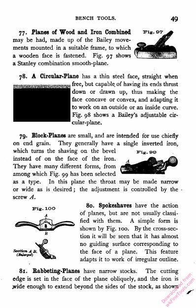
BENCH TOOLS. 49
77. Planes of Wood and Iron Combined
may be had, made up of the Bailey move
ments mounted in a suitable frame, to which
a wooden face is fastened. Fig. 97 shows
a Stanley combination smooth-plane.
Trig. 07
78.
Fig. O8
Fig. DO
A Circular-Plane has a thin steel face, straight when
free, but capable of having its ends thrust
down or drawn up, thus making the
face concave or convex, and adapting it
to work on an outside or an inside curve.
Fig. 98 shows a Bailey's adjustable cir
cular-plane.
79. Block-Planes are small, and are intended for use chiefly
on end grain. They generally have a single inverted iron,
which turns the shaving on the bevel
instead of on the face of the iron.
They have many different forms, from
among which Fig. 99 has been selected
as a type. In this plane the throat may be made narrow
or wide as is desired ; the adjustment is controlled by the
screw A.
80. Spokeshaves have the action
of planes, but are not usually classi
fied with them. A simple form is
shown by Fig. 100. By the cross-sec
tion it will be seen that it has almost
no guiding surface corresponding to
the face of a plane. This feature
adapts it to work of irregular outline.
Section A B.81. Rabbeting-Planes have narrow stocks. The cutting
edge is set in the face of the plane obliquely, and the iron is
.wide enough to extend beyond the sides of the stock, as shown
Downlo
aded
from
wkFine
Tools
.com

BENCH WORK IN WOOD.
Fig. lOl
by Fig. 101. Rabbeting-planes are designed for use in
interior angles. The oblique position of the iron produces a
shearing cut which promotes smooth
ness in action.
The shaving of the rabbeting-plane
instead of passing through the stock is
turned in such a way as to be dis
charged from one side ; an arrange
ment common to matching-planes, beading-planes, molding-
planes, and plows (82, 83, 84, and 85).
Fig. 10a82. Matching-Planes are used to form a tongue and a
groove, as shown respectively by a and b, Fig. 102.
Wooden matching-planes, Fig. 102, are
sold in pairs, one plane being fitted with a
single cutting edge, to form the groove, the
other with a double cutting edge, to form the
tongue. Both are guided by the " fence "
C, which moves in contact with the working
face of the piece operated upon. The
groove and the tongue should both be car
ried to as great a depth as the plane will
cut.
An iron matching-plane, designed to serve
the purpose of the two wooden ones, is now in general use.
Its fence is pivoted to the face in such a way that it can be
turned end for end ; in one position two cutters are exposed
103 and the plane is adjusted to form the tongue ;when its position is reversed, the fence covers one
of the cutting edges, and puts the plane in shape
for making the groove.
The size of matching-planes is indicated by the
N thickness of the material they are intended to
VJ match.
Ki8
A
n
Downlo
aded
from
wkFine
Tools
.com

BENCH TOOLS.
83. Hollow and Round are terms applied to such planes
as are shown by A and B, Fig. 103. They are used, as their
forms suggest, in producing hollows and in rounding projecting
edges. Their size is indicated by a number, or by the width of
the cutting edge.
Fig. 10c
n
ITig. 104
II
H
84. Beading-Planes are used in forming beads (220), and
they may be single or double, that is, form one or two
beads at a time. For beading on the edge of work,
they are provided with a fence, A, Fig. 104. For
use away from the edge, they are made to form three
or more beads at the same time, and have
no guide, in which case they are known as
reeding-planes, Fig. 105. The first three
beads are made with the plane guided by a straight
edge temporarily fastened to the surface of the work ;
- n,r I the remainder are formed by using those already
J-MJ made as a guide, the plane being moved into new
work at the rate of only one bead at a time. Other
beading-planes, more complicated than those described, are con
structed on much the same principle as a plow. The size of a
beading-plane is indicated by the width of the bead it will form.
85. Plows are used in making rectangular slots or " plows "
of any width, depth, and distance from the working-edge of
the material. The width of the cut is
ordinarily determined by the width of
the iron used. A set of irons is sup
plied with the tool, which is shown by
Fig. 106. A plow wider than the
widest iron can, of course, be made
by going over the work a second time.
The depth of the cut is regulated by
a little shoe (not shown) , which is raised or lowered by the
screw A. When this is adjusted, the tool can be used until
irig. ioe
Downlo
aded
from
wkFine
Tools
.com
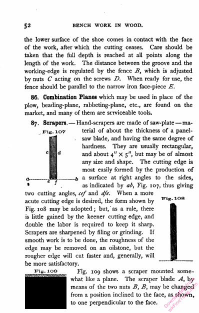
52 BENCH WORK IN WOOD.
Fig. 107
the lower surface of the shoe comes in contact with the face
of the work, after which the cutting ceases. Care should be
taken that the full depth is reached at all points along the
length of the work. The distance between the groove and the
working-edge is regulated by the fence B, which is adjusted
by nuts C acting on the screws D. When ready for use, the
fence should be parallel to the narrow iron face-piece E.
86. Combination Planes which may be used in place of the
plow, beading-plane, rabbeting-plane, etc., are found on the
market, and many of them are serviceable tools.
87. Scrapers.— Hand-scrapers are made of saw-plate —ma
terial of about the thickness of a panel-
saw blade, and having the same degree of
hardness. They are usually rectangular,
and about 4" X 5 ", but may be of almost
any size and shape. The cutting edge is
most easily formed by the production of
a surface at right angles to the sides,
• . as indicated by ab, Fig. 107, thus giving
two cutting angles, cef and dfe. When a more
acute cutting edge is desired, the form shown by
Fig. 108 maybe adopted; but, as a rule, there
is little gained by the keener cutting edge, and
double the labor is required to keep it sharp.
Scrapers are sharpened by filing or grinding. If
smooth work is to be done, the roughness of the
edge may be removed on an oilstone, but the
rougher edge will cut faster and, generally, will
be more satisfactory.
vis- 100 Fig. 109 shows a scraper mounted some
what like a plane. The scraper blade A, by
means of the two nuts B, B, may be changed
from a position inclined to the face, as shown,
to one perpendicular to the face.
Kig. 108
it
P B
Downlo
aded
from
wkFine
Tools
.com
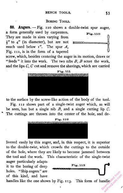
BENCH TOOLS.53
Boring Tools.
88. Augers. — Fig. 11o shows a double-twist spur auger,
Fig. noa form generally used by carpenters.
They are made in sizes varying from
-J" to 4" (in diameter), but are not
much used below 1". The spur A,
Fig. i11, is in the form of a tapered
screw, which, besides centering the auger in its motion, draws or
" feeds " it into the work. The two nibs B, B score the work,
and the lips C, C cut and remove the shavings, which are carried
Fig. m
to the surface by the screw-like action of the body of the tool.
Fig. 112 shows part of a single-twist auger which, as will
be seen, has but a single nib B, and a single cutting lip C.
The cuttings are thrown into the center of the hole, and de-
Fig. 11s
livered easily by this auger, and, in this respect, it is superior
to the double-twist, which crowds the cuttings to the outside
of the hole, where they are likely to become jammed between
the tool and the work. This characteristic of the single-twist
auger particularly adaptsit to the boring of deep Fis" 113holes. "Ship augers" are
of this kind, and have
handles like the one shown by Fig. 113. This form of handle
Downlo
aded
from
wkFine
Tools
.com

54BENCH WORK IN WOOD.
has the advantage of allowing the use of both hands, without the
interruption experienced in using the one illustrated by Fig. 11o.
Augers are seldom required by the bench-worker, but are
presented here because of their relation to other boring tools.
89. Auger-Bits. — The auger-bit most in use is shown byFig. 114. It is sold in sets of thirteen bits each, varying in
size by sixteenths, from i"■Fig. 114 ,. _- .... , ,
"^•C- 0v* * d-^ t0 is markec*
shank, which indicates its
size in the scale of sixteenths. Thus the figure 9 is to be inter
preted as T\".
90. Augers and auger-bits are sharpened by filing. The
scoring nib B, Figs, i11 and 112, which is usually the first part
to become dull, should be filed wholly from the inside. If
filed on the outside, the diameter of the cut it makes will be
smaller than that of the body of the bit. The cutting lip C
should be sharpened from the lower side, the file being inclined
to preserve the original angle. With the spur in good order,
whenever the tool refuses to " feed," it is clear that the bit
needs sharpening somewhere.
91. Center-Bits are convenient for boring holes of large
diameter in delicate material, such as would be likely to split
under the action of an auger-bit. By reference to Fig. 115, it
■ . _ will be seen that the spur A,Fig. 115 r '
which centers the bit in the
work, is triangular in section.
This form allows the bit to feed
rapidly, or very slowly, in accordance with the degree of pres
sure applied to it. The point, or "nib," B cuts the fibers about
the proposed hole, and the cutting lip C removes the material.
The center-bit does not work well in end grain. When dull it
may easily be sharpened by whetting.
Downlo
aded
from
wkFine
Tools
.com
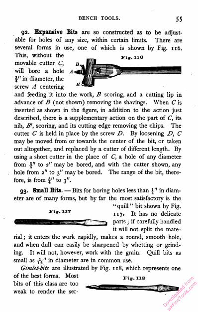
BENCH TOOLS.55
Wig. 11G
92. Expansive Bits are so constructed as to be adjust
able for holes of any size, within certain limits. There are
several forms in use, one of which is shown by Fig. 116.
This, without the
movable cutter C,
will bore a hole
|" in diameter, the
screw A centering
and feeding it into the work, B scoring, and a cutting lip in
advance of B (not shown) removing the shavings. When C is
inserted as shown in the figure, in addition to the action just
described, there is a supplementary action on the part of C, its
nib, B', scoring, and its cutting edge removing the chips. The
cutter C is held in place by the screw D. By loosening D, C
may be moved from or towards the center of the bit, or taken
out altogether, and replaced by a cutter of different length. By
using a short cutter in the place of C, a hole of any diameter
from f" to 2" may be bored, and with the cutter shown, any
hole from 2" to 3" maybe bored. The range of the bit, there
fore, is from f" to 3".
93. Small Bits. — Bits for boring holes less than \" in diam
eter are of many forms, but by far the most satisfactory is the
"quill " bit shown by Fig.
117. It has no delicate
parts ; if carefully handled
it will not split the mate
rial ; it enters the work rapidly, makes a round, smooth hole,
and when dull can easily be sharpened by whetting or grind
ing. It will not, however, work with the grain. Quill bits as
small as Ty in diameter are in common use.
Gimlet-bits are illustrated by Fig. 118, which represents one
of the best forms. Most Fig_ ns
bits of this class are too
weak to render the ser-Fig. 117-
Downlo
aded
from
wkFine
Tools
.com
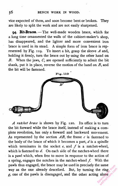
5<5 BENCH WORK IN WOOD.
vice expected of them, and soon become bent or broken. They
are likely to split the work and are not easily sharpened.
94. Bit-Braces. — The well-made wooden brace, which for
a long time ornamented the walls of the cabinet-maker's shop,
has disappeared, and the lighter and more convenient iron
brace is used in its stead. A simple form of iron brace is rep
resented by Fig. 119. To insert a bit, grasp the sleeve A and,
holding it firmly, turn the brace out by using the other hand on
B. When the jaws, C, are opened sufficiently to admit the bit
shank, put it in place, reverse the motion of the hand on B, and
the bit will be fastened.
Fig. 119A ratchet brace is shown by Fig. 120. Its office is to turn
the bit forward while the brace itself, instead of making a com
plete revolution, has only a forward and backward movement.
As represented by the section AB, the frame c is fastened to
the body of the brace of which it becomes a part, d is a spindle
which terminates in the socket e, and / is a ratchet-wheel,
which is fastened to d. On each side of the ratchet-wheel there
is a pawl which, when free to move in response to the action of
a spring, engages the notches in the ratchet-wheel /. With the
pawls thus engaged, the brace may be used in precisely the same
way as the one already described. But, by turning the ring
g, one of the pawls is disengaged, and the other acting alone
Downlo
aded
from
wkFine
Tools
.com

BENCH TOOLS. 57
will move the spindle d only when the brace is moving in one
direction, the pawl simply slipping* over the notches of the
ratchet-wheel when the motion is reversed. In this way, a
bit may be driven to any depth although each movement of
the brace may be less than half of a complete turn. By a
proper movement of the ring g, the motion of the bit may be
reversed.
Fig. ISO
Section A B.
(Enlarged)
The ratchet-brace is useful in boring holes near walls, or in
corners where it is impossible to turn a common brace.
The size of any brace is indicated by its " swing," that is,
by the diameter of the circle described by B, Fig. 119. The
better class are nickel-plated, and are thereby prevented from
rusting.
Downlo
aded
from
wkFine
Tools
.com
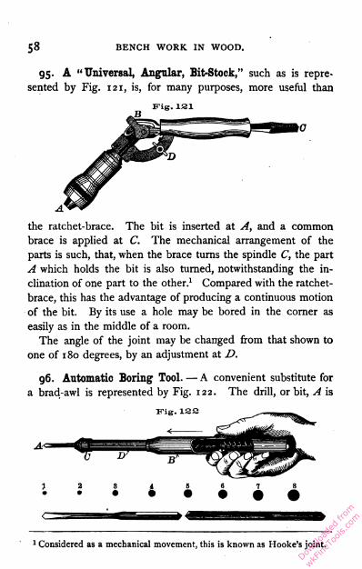
58 BENCH WORK IN WOOD.
95. A "Universal, Angular, Bit-Stock," such as is repre
sented by Fig. i21, is, for many purposes, more useful than
Fig. 121
the ratchet-brace. The bit is inserted at A, and a common
brace is applied at C. The mechanical arrangement of the
parts is such, that, when the brace turns the spindle C, the part
A which holds the bit is also turned, notwithstanding the in
clination of one part to the other.1 Compared with the ratchet-
brace, this has the advantage of producing a continuous motion
of the bit. By its use a hole may be bored in the corner as
easily as in the middle of a room.
The angle of the joint may be changed from that shown to
one of 180 degrees, by an adjustment at D.
96. Automatic Boring Tool. — A convenient substitute for
a brad-awl is represented by Fig. 122. The drill, or bit, A is
Fig. 12a
1 Considered as a mechanical movement, this is known as Hooke's joint.
Downlo
aded
from
wkFine
Tools
.com
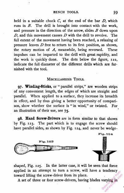
BENCH TOOLS.59
held in a suitable chuck C, at the end of the bar D, which
runs in B. The drill is brought into contact with the work,
and pressure in the direction of the arrow, slides B down upon
D, and this movement causes D with the drill to revolve. The
full extent of the movement having been reached, a relaxing of
pressure leaves D free to return to its first position, as shown,
the rotary motion of A, meanwhile, being reversed. These
impulses can be imparted to the drill with great rapidity, and
the work is quickly done. The dots below the figure, 122,
indicate the full diameter of the different drills which are fur
nished with the tool.
97. Winding-Sticks, or "parallel strips," are wooden strips
of any convenient length, the edges of which are straight and
parallel. When applied to a surface, they increase its breadth
in effect, and by thus giving a better opportunity of compari
son, show whether the surface is " in wind," or twisted. For
an illustration of their use, see 75.
98. Hand Screw-Drivers are in form similar to that shown
by Fig. 123. The part which is to engage the screw should
have parallel sides, as shown by Fig. 124, and never be wedge-
shaped, Fig. 125. In the latter case, it will be seen that force
applied in an attempt to turn a screw, will have a tendency
toward lifting the screw-driver from its place.A set of three or four screw-drivers, having blades varying in
Miscellaneous Tools.
Fig. 194
Downlo
aded
from
wkFine
Tools
.com

6o BENCH WORK IN WOOD.
Fig. ISO
size to suit different-sized screws, so that a fairly good fit may
always be made, are indispensable to good work where screwsare much used.
Fig. 135
99. Brace Screw-Drivers, instead of having
wooden handles, are provided with shanks for
use in a brace. A good form is shown by
Fig. 126. The brace gives a continuous mo
tion, and
the screw
may be
set much more rapidly by
its use than with the hand screw-driver. There are many cases,
however, in which a brace is useless.
100. Hammers.—Fig. 127 shows a carpenter's hammer. The
head A is wholly of steel. The face B is hardened so as not
to be injured by repeated blows upon the nail, which is com
paratively soft, but the idea prevailing among inexperienced
"workmen, that the hammer is indestructible, is a false one.
When two bodies are brought together forcibly, as a hammer
Fig. 137
B
and a nail, the softer body yields, and a change takes place in
its form. If the nail were harder than the hammer, it would not
be injured, but the hammer would show an impression of the
nail head. Careless or ignorant workmen sometimes take an
Downlo
aded
from
wkFine
Tools
.com
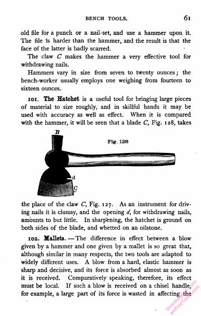
BENCH TOOLS. 61
old file for a punch or a nail-set, and use a hammer upon it.
The file Is harder than the hammer, and the result is that the
face of the latter is badly scarred.
The claw C makes the hammer a very effective tool for
withdrawing nails.
Hammers vary in size from seven to twenty ounces; the
bench-worker usually employs one weighing from fourteen to
sixteen ounces.
101. The Hatchet is a useful tool for bringing large pieces
of material to size roughly, and in skillful hands it may be
used with accuracy as well as effect. When it is compared
with the hammer, it will be seen that a blade C, Fig. 128, takes
the place of the claw C, Fig. 127. As an instrument for driv
ing nails it is clumsy, and the opening d, for withdrawing nails,
amounts to but little. In sharpening, the hatchet is ground on
both sides of the blade, and whetted on an oilstone.
102. Mallets. —The difference in effect between a blow
given by a hammer and one given by a mallet is so great that,
although similar in many respects, the two tools are adapted to
widely different uses. A blow from a hard, elastic hammer is
sharp and decisive, and its force is absorbed almost as soon as
it is received. Comparatively speaking, therefore, its effect
must be local. If such a blow is received on a chisel handle,
for example, a large part of its force is wasted in affecting the
Downlo
aded
from
wkFine
Tools
.com
62 BENCH WORK IN WOOD.
handle, a part only being transmitted through the handle to
the cutting edge, the only place where it can be of use. A
blow from a soft, less elastic mallet, on the contrary, is more
general in its effect. Much of the force remains for an instant
stored in the mallet, by which it is given out somewhat grad
ually, allowing time for the impulse to pass beyond the point
where it is received. The effect of two different explosive
agents will serve as an illustration. As compared with nitro
glycerine, powder burns slowly, and, when put into a rifle barrel,
gradually develops its force upon the bullet until, when the lat
ter reaches the end of the barrel, it has gained velocity enough
to carry it a mile or more. But if a charge of nitro-glycerine,
having a total explosive force no greater than that of the pow
der, be substituted, the result will be very different. The rapid
ity with which nitro-glycerine burns — the suddenness of the
impulse —is such that, before the bullet can respond to its influ
ence, the breach of the barrel is destroyed.
The blow of a mallet on a chisel resembles the action of
powder on a bullet. It is a pushing action, and, in this respect,
is unlike that of the hammer. A chisel, therefore, will be
driven deeper into the work by a blow from a mallet than by
one of the same force from a hammer, while a chisel handle
which has withstood blows from a mallet for years, may be
shattered in a single hour by use under a hammer.
An excellent form of mallet is shown by Fig. 129.
Downlo
aded
from
wkFine
Tools
.com
BENCH TOOLS. 63
103. Sand-Paper is neither a tool nor an appliance, strictly
speaking, but, on account of its tool-like action, it should be
mentioned with them. The "sand" used in making sand-paper
is crushed quartz, and is very hard, angular, and sharp. It is
graded as to degree of coarseness, by precipitation, and then
glued to paper. The finest sand-paper is marked 00, from which
the gradations run o, 1, i\, 2, 2^, and 3, which is the coarsest.
104. Miter-Boxes are useful in cutting the ends of light
strips of wood at an angle of 45 degrees ; they are frequently
adapted to cutting at other angles. When of wood, like the
one represented by Fig. 219, they are usually made by the
workman himself.
A wooden miter-box is composed of three pieces — a bot
tom and two sides. It is necessary that the bottom piece
be uniform in width and thickness, and have jointed edges, and
it is well to prepare the other pieces in the same way. After
the box is nailed, the sides should be square with the outside
face of the bottom piece ; this surface may now be used as
a working-face. Lay off across the working-face two lines at a
distance apart equal to the width of the face, thus forming with
the outside edges of the box, a square. The diagonals of this
square will represent the two oblique cuts, one marked c, and
the one taken by the saw, Fig. 219. Project up the sides such
lines from the points thus fixed, as will be useful in making the
cuts ; the sawing is then done with the back-saw. No special
directions are required for laying off the cut d.
105. Iron Miter-Boxes are
now in general use. The ac
curacy with which work may
be done by the use of one
will more than compensate any
bench-worker for the money
invested in it. Fig. 130 may be taken as a type ; the work A
Downlo
aded
from
wkFine
Tools
.com
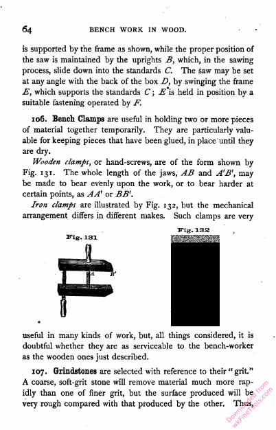
64 BENCH WORK IN WOOD.
is supported by the frame as shown, while the proper position of
the saw is maintained by the uprights B, which, in the sawing
process, slide down into the standards C, The saw may be set
at any angle with the back of the box D, by swinging the frame
E, which supports the standards C ; E is held in position by a
suitable fastening operated by F.
106. Bench Clamps are useful in holding two or more pieces
of material together temporarily. They are particularly valu
able for keeping pieces that have been glued, in place until they
are dry.
Wooden clamps, or hand-screws, are of the form shown by
Fig. 131. The whole length of the jaws, AB and A'B', may
be made to bear evenly upon the work, or to bear harder at
certain points, as AA' or BB'.
Iron clamps are illustrated by Fig. 132, but the mechanical
arrangement differs in different makes. Such clamps are very
Fig. 133
useful in many kinds of work, but, all things considered, it is
doubtful whether they are as serviceable to the bench-worker
as the wooden ones just described.
107. Grindstones are selected with reference to their "grit."
A coarse, soft-grit stone will remove material much more rap
idly than one of finer grit, but the surface produced will be
very rough compared with that produced by the other. Thus,
Downlo
aded
from
wkFine
Tools
.com

BENCH TOOLS. 65
when it is necessary to remove material for the purpose of giv
ing shape to a casting or forging, the coarse, soft-grit stone is
better ; but if a smooth cutting edge is required, one of fine
grit should be used. For wood-working tools, a stone rather
fine and soft is found best. The speed of a power grindstone
must vary from 500 to 1000 circumferential feet a minute, de
pending upon its diameter, and the accuracy and steadiness
with which it runs. It may not be well to run a 20" stone
beyond the minimum limit, while one of 4' or 5' may give good
results if run beyond the maximum. As a rule, a stone for
tool grinding is at its maximum speed when, if run faster, it
would throw water from its face.
By circumferential speed is meant the speed of the circumfer
ence of the stone. This is found by multiplying the diameter
of the stone, in feet, by 3.1416 (ratio of diameter to circum
ference), which will give the circumference of the stone, in feet,
and this product by the, number of revolutions per minute.1
1 Example I. — A 4' stone is run at 30 revolutions a minute; what is its
circumferential speed?The circumference of a 4' stone is
4'X3-I4!6= 12.56'.
This would be the speed of the stone if it were to make but I revolution
per minute; but, since it makes 30 revolutions, its speed is
12.56' X30= 376.80' or 377' (nearly).
Example II. — It is desired that a 30" stone should have a circumferen
tial speed of 280' per minute. How many revolutions should it make?
30" = 2.5'.
The circumference of a stone 2.5' in diameter is
2.5' x 3-1416= 7.85'.
This would be the speed of the stone if it were to make I revolution per
minute. But the circumferential speed is 280' per minute, and therefore
the number of revolutions made must be
280' -r- 7.85 = 36 (nearly).
Downlo
aded
from
wkFine
Tools
.com
66 BENCH WORK IN WOOD.
108. Water is used on a stone as a means of carrying off
the heat resulting from friction between stone and tool ; it also
washes away the particles of stone and steel that come from
the grinding, and which, without the water, would fill the inter
stices between the cutting points of the stone, and make the
surface so smooth as to be useless.
A grindstone, when not in use, should not stand in or over
water. Water softens a stone, and one unequally exposed to
moisture will be found softest in such places as are most
exposed. When brought into use, the softer parts wear away
more rapidly than the others, causing the stone to become " out
of round." Water is best supplied from a tank, or from service
pipes, so arranged that it may be shut off when the stone is not
running, the drip-pan under the stone being at all times per
fectly drained. After every precaution has been taken, the
stone will in time become untrue and need attention.
109. To True a Grindstone. — When a stone becomes
untrue, or the outline of the face, which should be slightly con
vex, becomes concave, it may be corrected by using a piece of
soft iron as a turning tool, the stone being run dry. The action
of the tool may be explained as follows : the soft iron allows
small particles of the stone to imbed themselves in its surface,
from which position they act against the revolving stone, and
the cutting is done by these imbedded particles and not by the
iron. The latter is worn in the process, however, and, as its
cutting surface becomes enlarged, it should be turned to bring
a new angle or face into action. This operation is easily per
formed by using a piece of gas pipe (about 1 ") for a turning tool.
no. Truing Devices are now generally attached to power
grindstones. They are of several forms, of which that shown
by Fig. 133 may be taken as an example. The base of this at
tachment is secured to the grindstone frame as near the stone as
may be convenient. A is a hardened steel screw which revolves
Downlo
aded
from
wkFine
Tools
.com
BENCH TOOLS. 67
freely on its bearings B. The frame in which B runs is pivoted
at C, in such a way that by a movement of the hand-wheel
D, B will move forward in the direction of the arrow. By
adjusting the hand-wheel D, A is brought into contact with the
face of the moving stone, and at once
begins to revolve. The action of its
thread would move it endwise, were
it not prevented by its bearings. The
effect of this angular advancement of
the thread, which is not met by a
corresponding lateral movement of
the parts in contact, is a shearing cut across the face of the
stone. When the screw becomes dull it may be softened and
recut.
in. Oilstones. — The most useful of all oilstones are
found near Hot Springs, Arkansas. They are divided into two
classes, known to the trade as the Arkansas stone and the
Washita stone. The former is of very fine grain, appearing
much like white marble. It is used in sharpening the most
delicate instruments, and produces an edge of remarkable
keenness. The Washita stone is much coarser in grain, with a
color sometimes almost white, but more frequently shaded by
lines of a reddish cast. It cuts with rapidity, and with much
greater delicacy than would be expected of so coarse a stone.
Probably no better oilstone exists for sharpening wood-working
and similar tools.
112. Oil is used on an oilstone for the same reason that
water is used on a grindstone. To be serviceable, it should be
as free as possible from all tendency to become thick or gummy.
A good quality of sperm oil, or even lard oil, may be used ; olive
oil is frequently recommended.
113. Form of Oilstones. — It is evident that if oilstones
could be made round, and mounted like grindstones, they could
Downlo
aded
from
wkFine
Tools
.com

68 BENCH WORK IN WOOD.
be used more effectively than when only a small block is avail
able. The reason they are not so mounted is that, in their
native bed, the whetstone layers are traversed in every direction
by veins of hard quartz, which, if allowed to enter into a finished
stone, would destroy the cutting edge of any tool that might
be applied to it. It is so uncommon to find large pieces of
whetstone free from the quartz, that disks above 4" or 5" in
diameter can be afforded only by those to whose work they are
indispensable.
For bench purposes, Washita stones are about 1" X 2" x 7";
but no attempt is made to have them
of any uniform size. Such a stone, when
set into a block and provided with a
cover to keep out the dust, is ready
for use. See Fig. 134. Its surface
should be kept as nearly as possible straight, in the direction of
its length, and should never be hollowed across its breadth.
When out of shape it must be trued.
B"ig. 134
Fig. 13G114. Slips of Washita stone whose cross-sections are round,
square, triangular, etc., are supplied
by the trade. A wedge-shaped slip
is represented by Fig. 135 ; it is a
form extremely useful to the bench-
worker.
115. To True an Oilstone, mix water with sharp sand until
the mixture is thin enough to run. Apply a quantity of this
to the surface of a flat board or plank, and, with the face that
is to be trued in contact with the sand-covered board, move
the stone about, frequently changing the direction of its motion.
Under this treatment, the surface of the stone will be evened
up rapidly. If the sand that is first applied becomes dull, it
may be replaced by new.
Downlo
aded
from
wkFine
Tools
.com

BENCH TOOLS. 69
Another, and usually a more convenient way, consists in sub
stituting for the sand a sheet of sand-paper tacked over the
edge of the board. Coarse paper may be used at first, and
afterwards a finer grade selected for finishing the work.
Downlo
aded
from
wkFine
Tools
.com

Downlo
aded
from
wkFine
Tools
.com

PART II.
BENCH WORK.1
116. No work at the bench (9-13) is more important than
that relating to the location and production of lines. Careless
ness or want of skill in this will always be manifest in the fin
ished work. To the beginner it may seem monotonous, and
even hard, to stand at the bench several hours before turning
a shaving ; but he must understand that a scratch cannot be
called a line, and that patience and accuracy are the chief
requisites m skillful manipulation.
117. Location of Points (14-17). — All measurements must
begin somewhere. The greater the number of points from which
to begin, the more chances there are for mistakes. Thus in
1 Note.—The material, or "stock," needed for the exercises of the
course should be straight-grained, free from knots, well-seasoned, and
machine-dressed. A good quality of either white pine or yellow poplar is
to be preferred. Good work cannot be done in poor material.
By easy steps the operations to be performed become more and more
difficult. The student should not advance to a new exercise until the pre
ceding one has been completed in a good, workman-like manner. A fail
ure, unless the result of accident, should invariably be followed by another
trial of the exercise. Otherwise, a careless habit is encouraged.
The course may appear brief, but experience has demonstrated its com
pleteness as a preparation for constructive work in any of the lines to
which it leads. After the fifteen exercises have been finished, if time
remains, any ordinary piece of bench work may be undertaken.
Downlo
aded
from
wkFine
Tools
.com
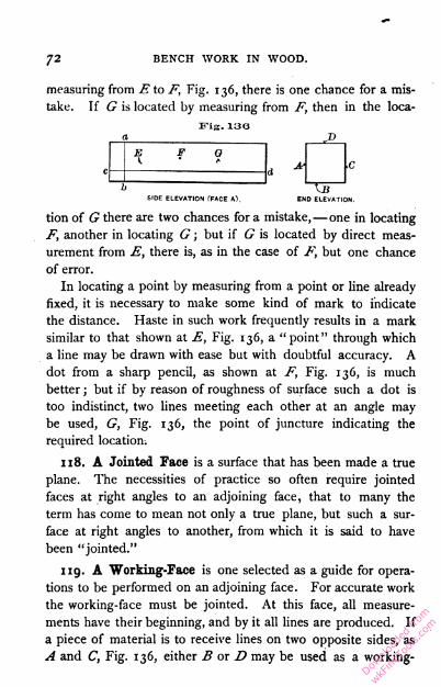
72 BENCH WORK IN WOOD.
measuring from E to F, Fig. 136, there is one chance for a mis
take. If G is located by measuring from F, then in the loca-
Fig. 130
E 0
b
dc
TITEND ELEVATION.SIDE ELEVATION fFACE A).
tion of G there are two chances for a mistake,—one in locating
F, another in locating G ; but if G is located by direct meas
urement from E, there is, as in the case of F, but one chance
of error.
In locating a point by measuring from a point or line already
fixed, it is necessary to make some kind of mark to indicate
the distance. Haste in such work frequently results in a mark
similar to that shown at E, Fig. 136, a "point" through which
a line may be drawn with ease but with doubtful accuracy. A
dot from a sharp pencil, as shown at F, Fig. 136, is much
better ; but if by reason of roughness of surface such a dot is
too indistinct, two lines meeting each other at an angle may
be used, G, Fig. 136, the point of juncture indicating the
required location.
118. A Jointed Face is a surface that has been made a true
plane. The necessities of practice so often require jointed
faces at right angles to an adjoining face, that to many the
term has come to mean not only a true plane, but such a sur
face at right angles to another, from which it is said to have
been "jointed."
119. A Working-Face is one selected as a guide for opera
tions to be performed on an adjoining face. For accurate work
the working-face must be jointed. At this face, all measure
ments have their beginning, and by it all lines are produced. If
a piece of material is to receive lines on two opposite sides, as
A and C, Fig. 136, either B or D may be used as a working
Downlo
aded
from
wkFine
Tools
.com

BENCH WORK.73
face, but not both ; if it is to receive lines on four faces, as A, B,
C, and D, two of them, as A and B, for example, must be work
ing-faces ; if on six faces, three must be working-faces. For
example, suppose lines are to be made on the surface A, Fig.
136, from B as a working-face ; those running across the piece,
as ab, will then be made perpendicular to B, and those running
lengthwise, as cd, parallel to B. If, on the contrary, the work
ing-face is disregarded, and some of the lines are made from
B and some from D, their truth will depend not only on the
truth of B and D as individual surfaces, but also upon their
parallelism, and hence there is a double chance of error. Only
one face, therefore, should be used from which to do the lining
for a given surface. If lines are to be made on all four sides,
as A, B, C, and D, and A and B are the working-faces, all
lines on A and C can be made from B, and all lines on B and
D can be made from A. It will be seen, therefore, that in
making a piece a true square in section, it is necessary to use
the beam of the square on only two faces.
EXERCISE No. r. — Measuring and Lining.
•120. The stock required is if inches thick, 4 inches wide,
and 4 feet long, or, as usually written, if" X 4" X 4'. Fig. 137
shows the completed exercise.1 To aid in following directions,
it will be well to letter the four faces of the work A, B, C, and
D, respectively, as indicated by Fig. 137 (End Elevation), and
to mark two of them, as A and B, working-faces.
Operations to be performed on Face A, from B as a
Working-Face, Fig. 137.
121. Spacing with Pencil and Rule (18). — By use ofpencil and rule, lay off points a, 1" apart along the whole
1 Fig. 137 is broken in accordance with the principles given in 6.
Downlo
aded
from
wkFine
Tools
.com

74 BENCH WORK IN WOOD.
length of the piece, the line of points being kept straight by
preserving a uniform distance between them and the working-
face B. This distance may be anything that is convenient,
and will be sufficiently accurate if determined by the eye.
Eng. 137'
Scale- 2— l'A' ..
)
*#1^4
Face .4.
Working Face A.
Working Face B.
b Od
Face B.
Gauj/eil Line* to he J" apart.
Face D.
0 Working Face B. g
Working Face A.
V
■ 1
•
>
END ELEVATION.
-16-
Face C
122. Cross-lining with Pencil and Framing-Square (19-
21). — The points having been located, draw through each a
line, as ab (Face A), using the framing-square and pencil.
Downlo
aded
from
wkFine
Tools
.com
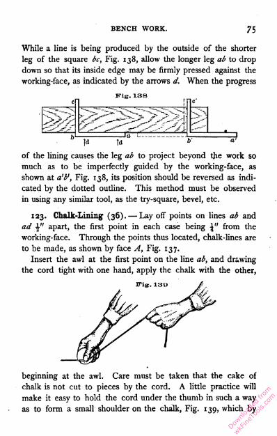
BENCH WORK.75
While a line is being produced by the outside of the shorter
leg of the square bc, Fig. 138, allow the longer leg ab to drop
down so that its inside edge may be firmly pressed against the
working-face, as indicated by the arrows d. When the progress
Fig. 138<n inc: .
hi la i 1 1]A Td b' a'
of the lining causes the leg ab to project beyond the work so
much as to be imperfectly guided by the working-face, as
shown at a'b', Fig. 138, its position should be reversed as indi
cated by the dotted outline. This method must be observed
in using any similar tool, as the try-square, bevel, etc.
123. Chalk-Lining (36). — Lay off points on lines ab and
ad \" apart, the first point in each case being \" from the
working-face. Through the points thus located, chalk-lines are
to be made, as shown by face A, Fig. 137.
Insert the awl at the first point on the line ab, and drawing
the cord tight with one hand, apply the chalk with the other,
beginning at the awl. Care must be taken that the cake of
chalk is not cut to pieces by the cord. A little practice will
make it easy to hold the cord under the thumb in such a way
as to form a small shoulder on the chalk, Fig. 139, which by
Downlo
aded
from
wkFine
Tools
.com
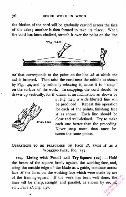
76 BENCH WORK IN WOOD.
the friction of the cord will be gradually carried across the face
of the cake ; another is then formed to take its place. When
the cord has been chalked, stretch it over the point on the line
ad that corresponds to the point on the line ab at which the
awl is inserted. Then raise the cord near the middle as shown
by Fig. 140, and by suddenly releasing it, cause it to " snap "
on the surface of the work. In snapping, the cord should be
drawn up vertically, for if drawn at an inclination as shown by
a, Fig. 141, a wide blurred line willbe produced. Repeat this operation
for each of the points, finishing face
A as shown. Each line should be
clear and well-defined. Try to make
each one better than the preceding.
Never snap more than once be
tween the same points.
Operations to be performed on Face B, from A as a
Working-Face, Fig. 137.
124. Lining with Pencil and Try-Square (22). — Hold
the beam of the square firmly against the working-face, and,
using the outside edge of the blade as a guide, continue across
face B the lines on the working-face which were made by use
of the framing-square. If the work has been well done, the
lines will be sharp, straight, and parallel, as shown by ab, cd,
etc., Face B, Fig. 137.
Downlo
aded
from
wkFine
Tools
.com
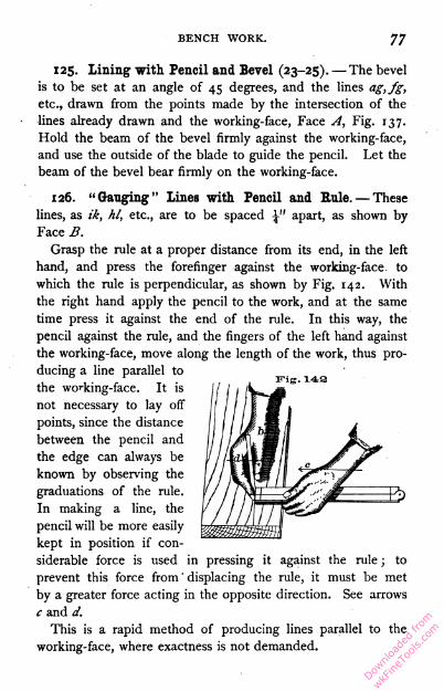
BENCH WORK. 77
125. Lining with Pencil and Bevel (23-25). — The bevel
is to be set at an angle of 45 degrees, and the lines ag,fg,
etc., drawn from the points made by the intersection of the
lines already drawn and the working-face, Face A, Fig. 137.
Hold the beam of the bevel firmly against the working-face,
and use the outside of the blade to guide the pencil. Let the
beam of the bevel bear firmly on the working-face.
126. "Ganging" lines with Pencil and Rule. — These
lines, as ik, hi, etc., are to be spaced \" apart, as shown by
Face B.
Grasp the rule at a proper distance from its end, in the left
hand, and press the forefinger against the working-face, to
which the rule is perpendicular, as shown by Fig. 142. With
the right hand apply the pencil to the work, and at the same
time press it against the end of the rule. In this way, the
pencil against the rule, and the fingers of the left hand against
the working-face, move along the length of the work, thus pro
ducing a line parallel to
the working-face. It is
not necessary to lay off
points, since the distance
between the pencil and
the edge can always be
known by observing the
graduations of the rule.
In making a line, the
pencil will be more easily
kept in position if con
siderable force is used in pressing it against the rule ; to
prevent this force from ' displacing the rule, it must be met
by a greater force acting in the opposite direction. See arrows
c and d.
This is a rapid method of producing lines parallel to the
working-face, where exactness is not demanded.
s
Downlo
aded
from
wkFine
Tools
.com
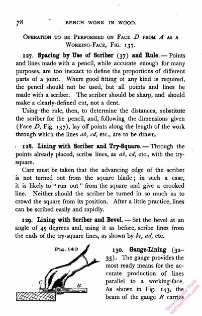
78 BENCH WORK IN WOOD.
Operation to be Performed on Face D from A as a
Working-Face, Fig. 137.
127. Spacing by Use of Scriber (37) and Rule. — Points
and lines made with a pencil, while accurate enough for many
purposes, are too inexact to define the proportions of different
parts of a joint. Where good fitting of any kind is required,
the pencil should not be used, but all points and lines be
made with a scriber. The scriber should be sharp, and should
make a clearly-defined cut, not a dent.
Using the rule, then, to determine the distances, substitute
the scriber for the pencil, and, following the dimensions given
(Face D, Fig. 137), lay off points along the length of the work
through which the lines ab, cd, etc., are to be drawn.
, 128. Lining with Scriber and Try-Square. — Through the
points already placed, scribe lines, as ab, cd, etc., with the try-
square.
Care must be taken that the advancing edge of the scriber
is not turned out from the square blade ; in such a case,
it is likely to " run out " from the square and give a crooked
line. Neither should the scriber be turned in so much as to
crowd the square from its position. After a little practice, lines
can be scribed easily and rapidly.
129. Lining with Scriber and Bevel. — Set the bevel at an
angle of 45 degrees and, using it as before, scribe lines from
the ends of the try-square lines, as shown by be, ad, etc.
130. Gauge-Lining (32-
35). The gauge provides the
most ready means for the ac
curate production of lines
parallel to a working-face.
As shown in Fig. 143, the
beam of the gauge B carries
Downlo
aded
from
wkFine
Tools
.com
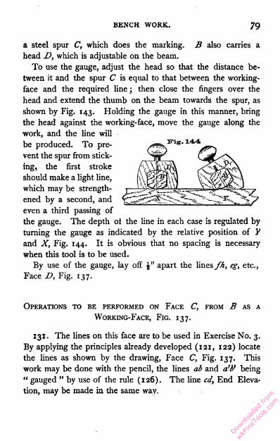
BENCH WORK.79
a steel spur C, which does the marking. B also carries a
head D, which is adjustable on the beam.
To use the gauge, adjust the head so that the distance be
tween it and the spur C is equal to that between the working-
face and the required line ; then close the fingers over the
head and extend the thumb on the beam towards the spur, as
shown by Fig. 143. Holding the gauge in this manner, bring
the head against the working-face, move the gauge along the
work, and the line will
be produced. To pre
vent the spur from stick
ing, the first stroke
should make a light line,
which may be strength
ened by a second, andeven a third passing ofthe gauge. The depth ot the line in each case is regulated by
turning the gauge as indicated by the relative position of Y
and X, Fig. 144. It is obvious that no spacing is necessary
when this tool is to be used.
By use of the gauge, lay off \" apart the lines fh, eg, etc.,
Face D, Fig. 137.
Operations to be performed on Face C, from B as a
Working-Face, Fig. 137.
131. The lines on this face are to be used in Exercise No. 3.
By applying the principles already developed (121, 122) locate
the lines as shown by the drawing, Face C, Fig. 137. This
work may be done with the pencil, the lines ab and a'P being
" gauged " by use of the rule (126). The line cd, End Eleva
tion, may be made in the same way.
Downlo
aded
from
wkFine
Tools
.com
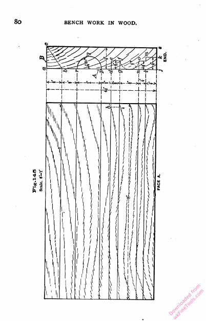
Downlo
aded
from
wkFine
Tools
.com

BENCH WORK. 81
EXERCISE No. 2.
Practice with Chisel and Gouge (39, 40, and 42).
The stock required is |" X 4^" X 8".
Fig. 145 shows the lines that are needed, all of which are
produced as explained in the foregoing exercise, except the
arcs of circles, which must be put in with the dividers (26) ;
A and B are working-faces. An end elevation of the finished
piece is represented by Fig. 146.
IPig.l4e
Fig. 147
132. To remove the Portion abc, Fig. 145.— It is always
best, in removing surplus wood with the chisel, to cut across
the grain, as any attempt to carry the cutting edge along
the grain is quite sure to result in a splitting action, the
chisel following the grain of the wood,
which splits ahead of it, and pre
vents the operator from controlling its
course. In removing the portion abc,
the work should be held in the vise with
the working-face A toward the operator.
A 1" chisel will be found of convenient
size. Beginning at one end, make suc
cessive cuts with the chisel, as shown
by Fig. 147. Each stroke of the chisel
should cut almost to the full depth re
quired (i.e. remove a shaving from the
face of nearly the whole triangle abc),
the thickness of the cutting varying with
the character of the material and the plan.
Downlo
aded
from
wkFine
Tools
.com

82 BENCH WORK IN WOOD.
strength of the operator. It is best, however, to go slowly, foi
the chisel will not be properly guided if the workman's whole
mig. 148 strength is required to push it throughthe wood. The surface thus produced
will not be smooth, but it will be true to
the line. To smooth it, a wide chisel
should be used, as shown by Fig. 148,
and a longitudinal movement impartedto it at the same time it is being pushed forward.
It will be noticed that both chisels are applied to the work
in such a way as to turn the shaving from the bevel, and not
from the flat face. This is done that the flat face may be avail
able as a guiding surface, which, when kept in contact with the
solid material back of the cut (see b, Fig. 148), will insure
straightness in the forward movement of the cutting edge, and,
consequently, accuracy of work.
133-
Fig. 149
1T,"*!f?l f
Lfiimk
To remove the Portion defg, Fig. 145. — With the
work flat on the bench, face A
uppermost, place a f" chisel so
as to bring its cutting edge in
the position occupied by the
line hi, which is about \" from
the end of the work. With the
mallet, drive the chisel verti
cally downward, as indicated by
c, Fig. 149. When down to the
depth of the required cut, the
chisel should be pushed over to
the position a, to make room
for the next cut, after which it
may be withdrawn and placed
Section A B. in position agam at (?> Th;s
operation* is to be repeated until the whole length of the piece
Downlo
aded
from
wkFine
Tools
.com
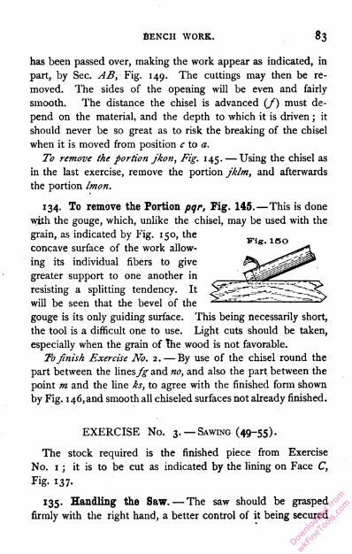
BENCH WORK. 83
has been passed over, making the work appear as indicated, in
part, by Sec. AB, Fig. 149. The cuttings may then be re
moved. The sides of the opening will be even and fairly
smooth. The distance the chisel is advanced (/) must de
pend on the material, and the depth to which it is driven ; it
should never be so great as to risk the breaking of the chisel
when it is moved from position c to a.
To remove the portion jkon, Fig. 145. — Using the chisel as
in the last exercise, remove the portion jklm, and afterwards
the portion Imon.
134. To remove the Portion pqr, Fig. 145.—This is done
with the gouge, which, unlike the chisel, may be used with the
grain, as indicated by Fig. 150, the
concave surface of the work allow
ing its individual fibers to give
greater support to one another in
resisting a splitting tendency. It
will be seen that the bevel of the
gouge is its only guiding surface. This being necessarily short,
the tool is a difficult one to use. Light cuts should be taken,
especially when the grain of the wood is not favorable.
Tofinish Exercise No. 2. — By use of the chisel round the
part between the linesy^ and no, and also the part between the
point m and the line ks, to agree with the finished form shown
by Fig. 1 46, and smooth all chiseled surfaces not already finished.
EXERCISE No. 3. — Sawing (49-55).
The stock required is the finished piece from Exercise
No. 1 ; it is to be cut as indicated by the lining on Face C,
Fig. 137.
135. Handling the Saw. — The saw should be grasped
firmly with the right hand, a better control of it being secured
Downlo
aded
from
wkFine
Tools
.com

84 BENCH WORK IN WOOD.
by extending the forefinger along the side of the handle. In
starting a cut, the side of the saw should be pressed against the
thumb of the left hand, which then acts as a guide, as shown
by Fig. 151. The saw must not be crowded against the work,
but, on the contrary, to prevent the teeth from penetrating too
deeply, its forward movement should be accompanied by a lift
ing action of the wrist. The saw should always be moved with
a long stroke, bringing as many teeth into action as possible. A
short, jerky movement is at no time necessary or desirable. It
is good practice for the beginner to keep up the proper motion
of the saw, while maintaining a very light contact between it
and the work. Success in this exercise is to be measured by
uniformity of contact throughout all points of the stroke.
There are two errors which are likely to be made in sawing :
first, sawing off the line; and, secondly, sawing at a wrong angle.
136. To guide the Saw. — If the saw tends to run off the
line, the blade may be slightly twisted in the direction it ought
to take, as shown by Fig. 152. It will immediately respond by
a change in its course. The correction should be made as
soon as the error is discovered.
Downlo
aded
from
wkFine
Tools
.com
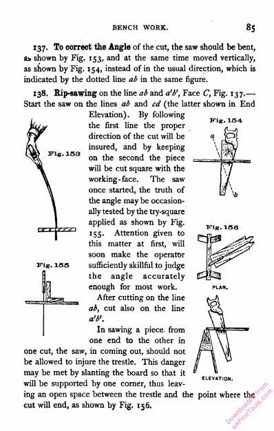
BENCH WORK. 85
JTig. 153
Fig. 154
137. To correct the Angle of the cut, the saw should be bent,
as shown by Fig. 153, and at the same time moved vertically,
as shown by Fig. 154, instead of in the usual direction, which is
indicated by the dotted line ab in the same figure.
138. Rip-sawing on the line ab and a'b', Face C, Fig. 137.—
Start the saw on the lines ab and cd (the latter shown in End
Elevation). By following
the first line the proper
direction of the cut will be
insured, and by keeping
on the second the piece
will be cut square with the
working -face. The saw
once started, the truth of
the angle may be occasion
ally tested by the try-square
applied as shown by Fig.
155. Attention given to
this matter at first, will
soon make the operator
sufficiently skillful to judge
the angle accurately
enough for most work.
After cutting on the line
ab, cut also on the line
a'b'.
In sawing a piece from
one end to the other in
one cut, the saw, in coming out, should not
be allowed to injure the trestle. This danger
may be met by slanting the board so that it
will be supported by one corner, thus leav
ing an open space between the trestle and the point where the
cut will end, as shown by Fig. 156.
Fig. 155
L
ELEVATION.
Downlo
aded
from
wkFine
Tools
.com
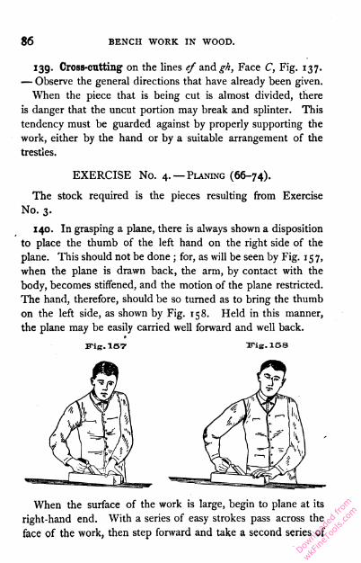
86 BENCH WORK IN WOOD.
139. Cross-cutting on the lines ef and^, Face C, Fig. 137.
— Observe the general directions that have already been given.
When the piece that is being cut is almost divided, there
is danger that the uncut portion may break and splinter. This
tendency must be guarded against by properly supporting the
work, either by the hand or by a suitable arrangement of the
trestles.
EXERCISE No. 4. — Planing (66-74).
The stock required is the pieces resulting from Exercise
No. 3.
140. In grasping a plane, there is always shown a disposition
to place the thumb of the left hand on the right side of the
plane. This should not be done ; for, as will be seen by Fig. 157,
when the plane is drawn back, the arm, by contact with the
body, becomes stiffened, and the motion of the plane restricted.
The hand, therefore, should be so turned as to bring the thumb
on the left side, as shown by Fig. 158. Held in this manner,
the plane may be easily carried well forward and well back.
ITig. 157 Ifig. 158
When the surface of the work is large, begin to plane at its
right-hand end. With a series of easy strokes pass across the
face of the work, then step forward and take a second series of
Downlo
aded
from
wkFine
Tools
.com

BENCH WORK. 87
strokes, and so on until the whole surface has been passed over.
In the first series of strokes it is necessary to draw the plane off
the work, as shown by Fig. 159. In doing this, sufficient
pressure must be exerted in the direc
tion of the arrow to overcome any
tendency to tip, as indicated by the
dotted outline ; in the last series of -
strokes the wrist may, for the same
reason, be rested easily on the back of the plane. To make
the strokes between the ends properly, the plane should be
lifted so that the shaving may be finished before the forward
movement of the plane ceases. The plane need not be lifted
bodily from the work. The natural, slightly-upward move
ment of the arm when stretched out, as shown by Fig. 160,
will accomplish all that is necessary.
EUg. ISO
If the plane is allowed full contact with the work on the
backward stroke, a dulling effect on the cutting edge is pro
duced, especially if the work is rough and gritty. Under
such circumstances, it is better to raise the plane from the
work entirely, or turn it on its edge, or draw it back in the
position shown by Fig. 160. On small, clean surfaces, how
ever, it is best to disregard this caution, since sharpening
Downlo
aded
from
wkFine
Tools
.com
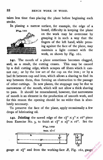
88 BENCH WORK IN WOOD.
JTig. 161
takes less time than placing the plane before beginning each
stroke.
In planing a narrow surface, for example, the edge of a
board, difficulty in keeping the plane
on the work may be overcome by
grasping it in such a way that the
fingers of the left hand, while press
ing against the face of the plane, may
maintain a light contact with the
work, as shown by Fig. 161.
141. The mouth of a plane sometimes becomes clogged,
and, as a result, the cutting ceases. This may be caused
by a dull cutting edge, which scrapes off fibers which it can
not cut ; or by the low set of the cap on the iron ; or by a
bad fit between cap and iron, which allows a shaving to find its
way between them, thus forming an obstruction to the passage
of other cuttings. In new planes, the stoppage may be due to
narrowness of the mouth, which will not allow a thick shaving
to pass. It should be remembered, however, that narrowness
of mouth is an element in the production of smooth work, and
for this reason the opening should be no wider than is abso
lutely necessary.
To preserve the face of the plane, apply occasionally a few
drops of lubricating oil.
142. Jointing the sawed edge of the if" X3" X 16" piece
from Exercise No. 3, to finish at if" X 2J" x 16". Set the
Fig. iea
Scale, if—l'
t
< 16- —,
/ b4
+
^B
gauge at 2|" and from the working-face B, Fig. 162, gauge
Downlo
aded
from
wkFine
Tools
.com

BENCH WORK. 89
lines all around the piece, as ef and bg. Fasten the piece in
the vise with the sawed edge up ; plane nearly to line with the
jack-plane and finish with the fore-plane.
143. Planing to a Square each of the four if" X 2" X 16"
pieces from Exercise No. 3, their finished size to be if" X if"
X 1 6". Select a straight face, or, if none is exactly right, cor
rect the best and mark it as a working-face. Let this be done
on each of the four pieces. All old marks are to mig.183
be planed off and new ones made as needed. Sup- D
pose Fig. 163 to represent an end of one of the
pieces, and let A be its working-face. With the
fore-plane, joint B from A, and mark B as a second
working-face. Repeat this operation on each of the other
pieces. Set the gauge at if" (the width to which each side
is to finish), and from the working-face A gauge a line on B.
From working-face B joint C to line, and perform this opera
tion on each remaining piece. From B as a working-face
with the. gauge set as before, produce lines on A and C, and
plane D to these lines. This done, the four pieces should be
of the same size, and true squares in section.
144. Whenever a series of similar operations is to be per
formed on two or more pieces, the method developed by the
foregoing exercise should always be followed. By carrying all
the pieces along together, the work will be most easily and
most rapidly accomplished.
145. Smooth Surfaces cannot always be produced by a
plane. The presence of knots or a crooked grain causes the
work to split in advance of the cutting edge, and a rough sur
face results. A sharp plane set to take a fine shaving, will
do much to remedy this evil, but it cannot be entirely over
come. Surfaces, such as a table top or a door panel, which
are not required to be true, may be made as smooth as possible
Downlo
aded
from
wkFine
Tools
.com
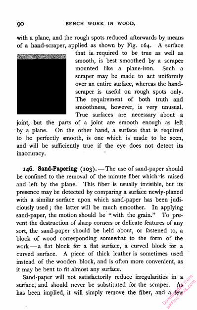
go BENCH WORK IN WOOD,
with a plane, and die rough spots reduced afterwards by means
of a hand-scraper, applied as shown by Fig. 164. A surface
that is- required to be true as well as
smooth, is best smoothed by a scraper
mounted like a plane-iron. Such a
scraper may be made to act uniformly
over an entire surface, whereas the hand-
scraper is useful on rough spots only.
The requirement of both truth and
smoothness, however, is very unusual.
True surfaces are necessary about a
joint, but the parts of a joint are smooth enough as left
by a plane. On the other hand, a surface that is required
to be perfectly smooth, is one which is made to be seen,
and will be sufficiently true if the eye does not detect its
inaccuracy.
146. Sand-Papering (103). —The use of sand-paper should
be confined to the removal of the minute fiber which is raised
and left by the plane. This fiber is usually invisible, but its
presence may be detected by comparing a surface newly-planed
with a similar surface upon which sand-paper has been judi
ciously used ; the latter will be much smoother. In applying
sand-paper, the motion should be " with the grain." To pre
vent the destruction of sharp corners or delicate features of any
sort, the sand-paper should be held about, or fastened to, a
block of wood corresponding somewhat to the form of the
work — a flat block for a flat surface, a curved block for a
curved surface. A piece of thick leather is sometimes used
instead of the wooden block, and is often more convenient, as
it may be bent to fit almost any surface.
Sand-paper will not satisfactorily reduce irregularities in a
surface, and should never be substituted for the scraper. As
has been implied, it will simply remove the fiber, and a few
Downlo
aded
from
wkFine
Tools
.com
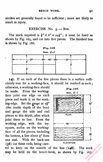
BENCH WORK. 91
strokes arc generally found to be sufficient ; more are likely to
result in injury.
EXERCISE No. 5. — Box.
The stock required is $■ " X 6"X 24^"; it must be lined as
shown by Fig. 165, and cut into five pieces. The finished box
is shown by Fig. 166.
Fig. 165
Scale, 11—l'
IU, i iv
jr1
-10-i-
I.6"
i
147. If on each of the five pieces there is a surface suffi
ciently true for a working-face, it should be marked as such ;
otherwise, a working-face should
be made. From the working-
face joint one edge on each
piece and mark it as the work
ing-edge. Set the gauge at 2f"
(the inside depth of the box)
and gauge the side and end
pieces to this depth, after which
joint them to line. From the
working edge, with the try-
square, scribe on the working-
face of all the pieces, including
the bottom, a line about \" from
one end. With the back-saw
(56) cut these ends, being care
ful to keep on the outside of the line (148). The work
may be held on the bench-hook, as shown by Fig. 167.
ELEVATION
Downlo
aded
from
wkFine
Tools
.com

92 BENCH WORK IN WOOD.
In starting the cut, the saw may be made to act across the
angle of the work in the direction of the line ab, but should
gradually be brought to the position shown, its motion being
parallel to the face of the work, and its stroke long enough to
bring every tooth into action. The position of the saw in Fig.
167, together with the dotted outline, shows a proper range of
movement.
The ends, when sawed, should be square with the work
ing-face and working-edge. If the cut is a poor one, a
second may be taken by removing just enough material to
hold the saw; if it is only a little "out," it will be best, in
this case, to pass the error for a time. One end of each hav
ing been squared, the pieces may now be brought to length.
On one of the two pieces which are to form the ends of the
box, lay off and scribe a line 4" from the squared end. Meas
ure the second end piece by the first to insure the same length
for both, whether the measurement is just 4" or not. Next, on
one of the two side pieces, g\" from the squared end, scribe a
line for sawing and, using the first piece as a measure, lay off a
similar line on the second side piece and also on the bottom
piece. All the pieces having been thus lined, they may be cut
with the back-saw, after which all but the bottom piece will be
of the dimensions required.
148. Sawing " outside of the line" may be illustrated as fol
lows : if two lines are made on a piece of work just 12" apart,
and the portion between cut out by sawing exactly on the lines,
Downlo
aded
from
wkFine
Tools
.com

BENCH WORK.93
it is obvious that th^ piece will be less than 12" long by half
the width of the saw kerf at each end, or, adding the two de
ficiencies, by the width of one kerf, or more.
The appearance of an end when cut outside of a Fls' 188line will be that shown by Fig. 168. The smooth E^Hlline along the upper surface, represents the cut
made by the scriber in lining the material ; the rest shows the
work of the saw.
149. Nailing (254-256). —The side and end pieces are to
be nailed, as shown by Fig. 169, three 6-penny casing nails
being used at each angle. When brought together, the pieces
must be flush — pretty nearly right will not do.
Nails, when seen in a certain position, appear equal in width
throughout their length, A, Fig. 1 70 ; while a view at right
angles to the first, shows them wedge-shaped, B, Fig. 170. In
Fig. 160
E"ig. 170
A B
PLAN.
WORKING EDGE
ELEVATION.
starting a nail, the line represented by a must be placed across
the grain of the wood, so that the point will cut the fibers
which are displaced. If the line b is placed across the grain,
a few only of the fibers will be severed, and the others will be
simply pressed apart by the inclined sides of the nail, an action
which is quite likely to split the work.
Downlo
aded
from
wkFine
Tools
.com
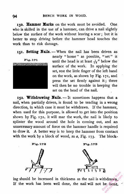
94BENCH WORK IN WOOD.
150. Hammer Marks on the work must be avoided. One
who is skilled in the use of a hammer, can drive a nail slightly
below the surface of the work without leaving a scar ; but it is
better to stop driving before the hammer head touches the
work than to risk damage.
151. Setting Nails. — When the nail has been driven as
nearly " home " as possible, " set " it
until the head is at least j\ " below the
surface of the work. In applying the
set, rest the little finger of the left hand
on the work, as shown by Fig. 171, and
press the set firmly against it ; there
will then be no trouble in keeping the
set on the head of the nail.
152. Withdrawing Nails. — It sometimes happens that a
nail, when partially driven, is found to be tending in a wrong
direction, in which case it must be withdrawn. If the hammer,
when used for this purpose, is allowed to get into the position
shown by Fig. 172, it will mar the work, the nail is likely to
splinter the wood around the hole in coming out, and an
unnecessary amount of force on the hammer handle is required
to draw it. A better way is to keep the hammer from contact
with the work by a block of wood, as a, Fig. 1 73. The block
ing. 17S irig.173
ing should be increased in thickness as the nail is withdrawn.
If the work has been well done, the nail will not be bent.
Downlo
aded
from
wkFine
Tools
.com
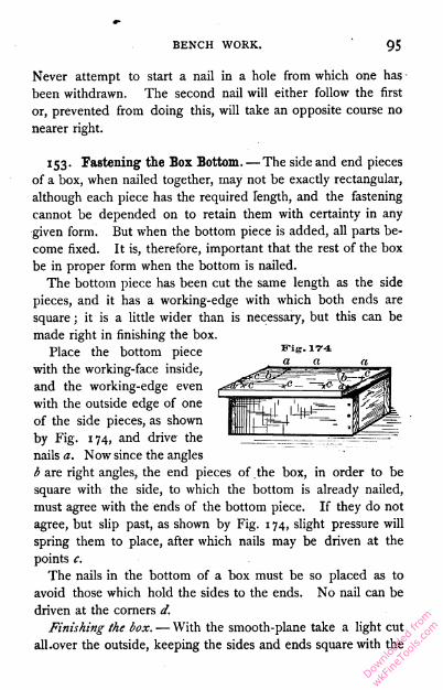
BENCH WORK. 95
Never attempt to start a nail in a hole from which one has -been withdrawn. The second nail will either follow the first
or, prevented from doing this, will take an opposite course no
nearer right.
153. Fastening the Box Bottom. — The side and end pieces
of a box, when nailed together, may not be exactly rectangular,
although each piece has the required length, and the fastening
cannot be depended on to retain them with certainty in any
given form. But when the bottom piece is added, all parts be
come fixed. It is, therefore, important that the rest of the box
be in proper form when the bottom is nailed.
The bottom piece has been cut the same length as the side
pieces, and it has a working-edge with which both ends are
square ; it is a little wider than is necessary, but this can be
made right in finishing the box.
Place the bottom piece
with the working-face inside,
and the working-edge even
with the outside edge of one
of the side pieces, as shown
by B"ig. 174, and drive the
nails a. Now since the angles
b are right angles, the end pieces of the box, in order to be
square with the side, to which the bottom is already nailed,
must agree with the ends of the bottom piece. If they do not
agree, but slip past, as shown by Fig. 1 74, slight pressure will
spring them to place, after which nails may be driven at the
points c.
The nails in the bottom of a box must be so placed as to
avoid those which hold the sides to the ends. No nail can be
driven at the corners d.
Finishing the box. — With the smooth-plane take a light cut
all.over the outside, keeping the sides and ends square with the
Downlo
aded
from
wkFine
Tools
.com
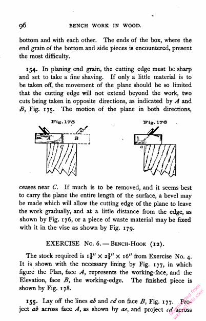
96 BENCH WORK IN WOOD.
bottom and with each other. The ends of the box, where the
end grain of the bottom and side pieces is encountered, present
the most difficulty.
154. In planing end grain, the cutting edge must be sharp
and set to take a fine shaving. If only a little material is to
be taken off, the movement of the plane should be so limited
that the cutting edge will not extend beyond the work, two
cuts being taken in opposite directions, as indicated by A and
B, Fig. 175. The motion of the plane in both directions,
ceases near C. If much is to be removed, and it seems best
to carry the plane the entire length of the surface, a bevel may
be made which will allow the cutting edge of the plane to leave
the work gradually, and at a little distance from the edge, as
shown by Fig. 176, or a piece of waste material may be fixed
with it in the vise as shown by Fig. 179.
EXERCISE No. 6. — Bench-Hook (12).
The stock required is if" X 2§" X 16" from Exercise No. 4.
It is shown with the necessary lining by Fig. 177, in which
figure the Plan, face A, represents the working-face, and the
Elevation, face B, the working-edge. The finished piece is
shown by Fig. 1 78.
155. Lay off the lines ab and cd on face B, Fig. 177. Pro
ject ab across face A, as shown by ae, and project cd across
Fig. 175
Downlo
aded
from
wkFine
Tools
.com
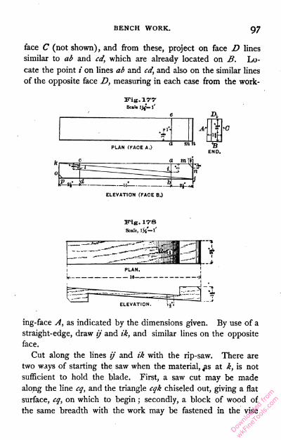
BENCH WORK.97
face C (not shown), and from these, project on face D lines
similar to ab and cd, which are already located on B. Lo
cate the point i on lines ab and cd, and also on the similar lines
of the opposite face D, measuring in each case from the work-
Scale l'
ELEVATION (FACE BJ
ITlg. 17-8
Scale, I)/"!'
ing-face A, as indicated by the dimensions given. By use of a
straight-edge, draw if and ik, and similar lines on the opposite
face.
Cut along the lines if and ik with the rip-saw. There are
two ways of starting the saw when the material, £s at k, is not
sufficient to hold the blade. First, a saw cut may be made
along the line cg, and the triangle cqk chiseled out, giving a flat
surface, cq, on which to begin ; secondly, a block of wood of
the same breadth with the work may be fastened in the vise
Downlo
aded
from
wkFine
Tools
.com
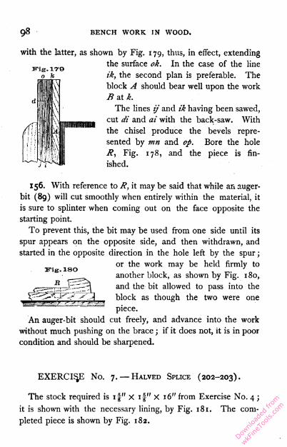
98 BENCH WORK IN WOOD.
irig.17'9
with the latter, as shown by Fig. 179, thus, in effect, extending
the surface ok. In the case of the line
ik, the second plan is preferable. The
block A should bear well upon the work
B at k.
The lines ij and ik having been sawed,
cut di and at with the back-saw. With
the chisel produce the bevels repre
sented by tnn and op. Bore the hole
R, Fig. 178, and the piece is fin
ished.
156. With reference to R, it may be said that while an auger-
bit (89) will cut smoothly when entirely within the material, it
is sure to splinter when coming out on the face opposite the
starting point.
To prevent this, the bit may be used from one side until its
spur appears on the opposite side, and then withdrawn, and
started in the opposite direction in the hole left by the spur ;
or the work may be held firmly to
another block, as shown by Fig. 180,
and the bit allowed to pass into the
block as though the two were one
piece.
An auger-bit should cut freely, and advance into the work
without much pushing on the brace ; if it does not, it is in poor
condition and should be sharpened.
mig. lsoEXERCISE No. 7. — Halved Splice (202-203).
The stock required is if" X if" X 16" from Exercise No. 4 ;
it is shown with the necessary lining, by Fig. 181. The com
pleted piece is shown by Fig. 182.
Downlo
aded
from
wkFine
Tools
.com
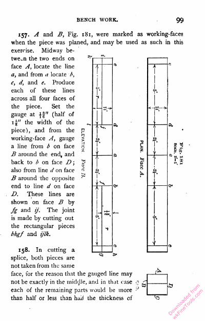
BENCH WORK. 99
'S
is
158. In cutting a
splice, both pieces are ~~
not taken from the same
face, for the reason that the gauged line may
not be exactly in the middle, and in that case
each of the remaining parts would be more
than half or less than hail the thickness of
157. A and B, Fig. 181, were marked as working-faces
when the piece was planed, and may be used as such in this
exercise. Midway be
tween the two ends on
face A, locate the line
a, and from a locate b,
c, d, and e. Produce
each of these lines
across all four faces of
the piece. Set the
gauge at \\" (half of
1 1" the width of the
piece), and from the
working-face A, gauge
a line from b on face
B around the end, and
back to b on face D ;
also from line d on face
B around the opposite
end to line d on face
D. These lines are
shown on face B by
fg and if. The joint
is made by cutting out
the rectangular pieces
bhgf and ifIk.
i
* -
I 00
Downlo
aded
from
wkFine
Tools
.com
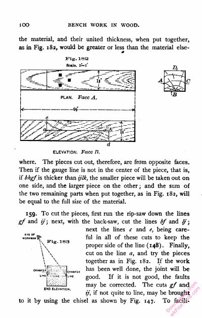
BENCH WORK IN WOOD.
the material, and their united thickness, when put together,
as in Fig. 182, would be greater or less than the material else-
Fig. 183
Scale, 3-l'
plan. Face A.
-9f
elevation. Face It.
where. The pieces cut out, therefore, are from opposite faces.
Then if the gauge line is not in the center of the piece, that is,
if Mgf is thicker than ijlk, the smaller piece will be taken out on
one side, and the larger piece on the other ; and the sum of
the two remaining parts when put together, as in Fig. 182, will
be equal to the full size of the material.
159. To cut the pieces, first run the rip-saw down the lines
gf and if; next, with the back-saw, cut the lines bf and If ;
next the lines c and e, being care
ful in all of these cuts to keep the
proper side of the line (148). Finally,
cut on the line a, and try the pieces
together as in Fig. 182. If the work
has been well done, the joint will be
good. If it is not good, the faults
may be corrected. The cuts gf and
if, if not quite to line, may be brought
to it by using the chisel as shown by Fig. 147. To facili-
CHAMFEfl
END ELEVATION.
Downlo
aded
from
wkFine
Tools
.com
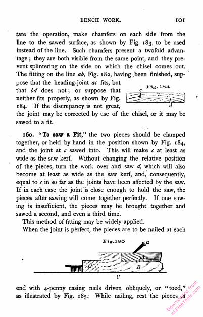
BENCH WORK. IOI
tate the operation, make chamfers on each side from the
line to the sawed surface, as shown by Fig. 183, to be used
instead of the line. Such chamfers present a twofold advan
tage ; they are both visible from the same point, and they pre
vent splintering on the side on which the chisel comes out.
The fitting on the line ab, Fig. 182, having .been finished, sup
pose that the heading-joint ac fits, but
that bd does not ; or suppose that
neither fits properly, as shown by Fig.
184. If the discrepancy is not great,
the joint may be corrected by use of the chisel, or it may be
sawed to a fit.
160. "To saw a Fit," the two pieces should be clamped
together, or held by hand in the position shown by Fig. 184,
and the joint at c sawed into. This will make c at least as
wide as the saw kerf. Without changing the relative position
of the pieces, turn the work over and saw d, which will also
become at least as wide as the saw kerf, and, consequently,
equal to c in so far as the joints have been affected by the saw.
If in each case the joint"is close enough to hold the saw, the
pieces after sawing will come together perfectly. If one saw
ing is insufficient, the pieces may be brought together and
sawed a second, and even a third time.
This method of fitting may be widely applied.
When the joint is perfect, the pieces are to be nailed at each
end with 4-penny casing nails driven obliquely, or "toed,"
as illustrated by Fig. 185. While nailing, rest the pieces A
Downlo
aded
from
wkFine
Tools
.com
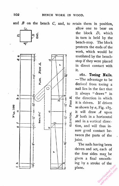
102 BENCH WORK IN WOOD.
and B on the bench C, and, to retain them in position,
allow one to bear on
the block Z>, which
in turn is held by the
bench-stop. The block
protects the ends of the
work, which would be
mutilated by the bench-
stop if they were placed
in direct contact with
it.
161. Toeing Nails.
—The advantage to be
derived from toeing a
nail lies in the fact that
it always " draws " in
the direction in which
it is driven. If driven
as shown by a, Fig. 185,
it will draw A upon
B both in a horizontal
and in a vertical direc
tion, and will thus in
sure good contact be
tween the parts of the
joint.
The nails having been
driven and set, each of
the four sides may be
given a final smooth
ing by a stroke of the
plane.
Downlo
aded
from
wkFine
Tools
.com
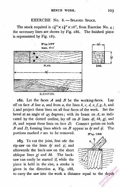
BENCH WORK. IO3
EXERCISE No. 8.— Splayed Splice.
The stock required is if'x if'X 16", from Exercise No. 4 ;
the necessary lines are shown by Fig. 186. The finished piece
is represented by Fig. 187.
Scale- 3—l'
162. Let the faces A and B be the working-faces. Lay
off on face A line a, and from a, the lines b, c, d, e,f, g, h, and
i, and project these lines on all four faces of the work. Set the
bevel at an angle of 45 degrees ; with its beam on A, as indi
cated by the dotted outline, lay off on B lines dj, bk, gj, and
ik, and repeat these lines on face D. Connect points on both
B and D, forming lines which on B appear as bj and if. The
portions marked r are to be removed.
163. To cut the joint, first uSe the
rip-saw on the lines bj and if, and
afterwards the back-saw on the short
oblique lines gj and bk. The back-
saw can easily be started if, while the
piece is held in the vise, a stroke is
given in the direction a, Fig. 188,
to carry the saw into the work a distance equal to the depth
Downlo
aded
from
wkFine
Tools
.com
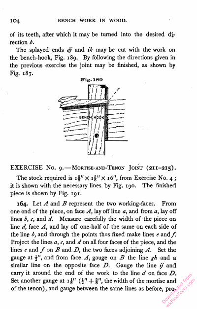
104 BENCH WORK IN WOOD.
of its teeth, after which it may be turned into the desired di
rection b.
The splayed ends dj and ik may be cut with the work on
the bench-hook, Fig. 189. By following the directions given in
the previous exercise the joint may be finished, as shown by
Fig. 187.
EXERCISE No. 9.—Mortise-and-Tenon Joint (211-215).
The stock required is if" X if" X 16", from Exercise No. 4 ;
it is shown with the necessary lines by Fig. 190. The finished
piece is shown by Fig. 191.
164. Let A and B represent the two working-faces. From
one end of the piece, on face A, lay off line a, and from a, lay off
lines b, c, and d. Measure carefully the width of the piece on
line d, face A, and lay off one-half of the same on each side of
the line b, and through the points thus fixed make lines e and f.
Project the lines a, c, and d on all four faces of the piece, and the
lines e and / on B and D, the two faces adjoining A. Set the
gauge at \", and from face A, gauge on B the line gh and a
similar line on the opposite face D. Gauge the line if and
carry it around the end of the work to the line d on face D.
Set another gauge at 1^" (£" + f", the width of the mortise and
of the tenon) , and gauge between the same lines as before, pro-
Fig. 180
Downlo
aded
from
wkFine
Tools
.com
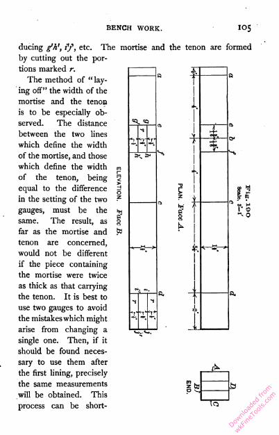
BENCH WORK.
JC-
S » H
0
during g'A', if, etc. The mortise and the tenon are formed
by cutting out the por
tions marked r.
The method of "lay
ing off" the width of the
mortise and the tenon
is to be especially ob
served. The distance
between the two lines
which define the width
of the mortise, and those
which define the width
of the tenon, being
equal to the difference
in the setting of the two
gauges, must be the
same. The result, as
far as the mortise and
tenon are concerned,
would not be different
if the piece containing
the mortise were twice
as thick as that carrying
the tenon. It is best to
use two gauges to avoid
the mistakeswhich might
arise from changing a
single one. Then, if it
should be found neces
sary to use them after
the first lining, precisely
the same measurements
will be obtained. This
process can be short-
si ft,
to
To"
Downlo
aded
from
wkFine
Tools
.com

io6 BENCH WORK IN WOOD.
ened by using a mortise-gauge (33), which makes both lines at
the same time.
165. Cutting the Mortise. — It will be remembered that the
lines which appear on face B, Fig. 190, have their counterparts
SIDE. END.
on the opposite face D. To cut the mortise, select a chisel
having a width as nearly as possible equal to the space between
the gauge lines, and, beginning on face B, near the middle of
the mortise, advance toward one end, as shown by Fig. 149.
The end of the mortise having been reached, commence at the
starting point and advance to the other end. Always loosen
the chisel by a backward movement of the handle ; a movement
in the opposite direction would injure the ends of the mortise.
(See Fig. 149.) After the first few cuts, each deeper than the
preceding, the chisel can easily be made to penetrate an inch
or more, in pine or poplar. If the depth is equal to half the
thickness of the work, no attention need be given to the chips.
One side of the mortise having been cut in this manner, turn
the work over and repeat the operation on face D, the chisel
Downlo
aded
from
wkFine
Tools
.com
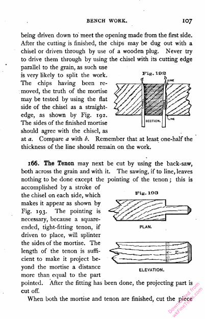
BENCH WORK. I07
being driven down to meet the opening made from the first side.
After the cutting is finished, the chips may be dug out with a
chisel or driven through by use of a wooden plug. Never try
to drive them through by using the chisel with its cutting edge
parallel to the grain, as such use
is very likely to split the work.
The chips having been re
moved, the truth of the mortise
may be tested by using the flat
side of the chisel as a straight
edge, as shown by Fig. 192.
The sides of the finished mortise
should agree with the chisel, as
at a. Compare a with b. Remember that at least one-half the
thickness of the line should remain on the work.
166. The Tenon, may next be cut by using the back-saw,
both across the grain and with it. The sawing, if to line, leaves
nothing to be done except the pointing of the tenon ; this is
accomplished by a stroke of
the chisel on each side, which
makes it appear as shown by
Fig. 193. The pointing is
necessary, because a square-
ended, tight-fitting tenon, if
driven to place, will splinter
the sides of the mortise. The
length of the tenon is suffi
cient to make it project be
yond the mortise a distance
more than equal to the part
pointed. After the fitting has been done, the projecting part is
cut off.
When both the mortise and tenon are finished, cut the piece
Fig. 183
ELEVATION.
Downlo
aded
from
wkFine
Tools
.com

108 BENCH WORK IN WOOD.
on the line e, Fig. 190, and try the tenon in the mortise. It
should enter at a light-driving fit. If the shoulders of the tenon
do not make a good joint with the cheeks of the mortise, that
is, if the joint at S, Fig. 191, is not good, it may be sawed to a
fit, as in the case of the splice. When all is satisfactory, bore
the pin hole, insert the pin, cut off the projecting portion of the
tenon and of the pin, and take a light shaving from those sur
faces on which a plane may be used.
167. To Make a Pin (249). — Select a piece of straight-
grained material, in this case 4" or 5" long, and, by use of the
chisel, reduce it in section to a square whose side is slightly
greater than the diameter of the hole it is to fit. Then take off
the corners, making it an octagon in section, and point one
E-ig. 104
end. All this will be best accomplished if the piece is held
by the bench-hook, as indicated by Fig. 194.
168. Drawboring is a term applied to a method of locating
pin holes so as to make
the pin draw the tenon
into the mortise. Fig.
195 shows the relative
position of the holes be
fore the pin is inserted.
It is evident that a
tight-fitting pin will have
a tendency to make the holes in the mortise and tenon
coincide, and thus draw the two pieces together. The holes
Downlo
aded
from
wkFine
Tools
.com
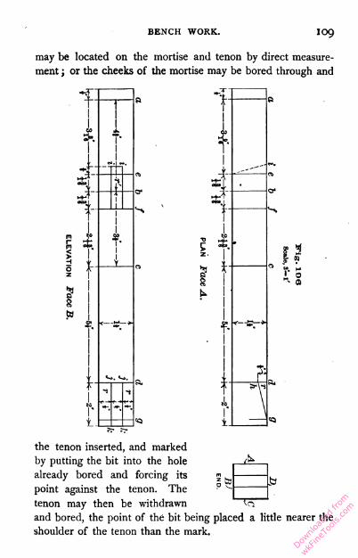
BENCH WORK. IO9
may be located on the mortise and tenon by direct measure
ment ; or the cheeks of the mortise may be bored through and
the tenon inserted, and marked
by putting the bit into the hole
already bored and forcing its
point against the tenon. The
tenon may then be withdrawn
and bored, the point of the bit being placed a little nearer the
shoulder of the tenon than the mark.
To"
Downlo
aded
from
wkFine
Tools
.com
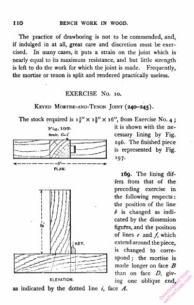
no BENCH WORK IN WOOD.
The practice of drawboring is not to be commended, and,
if indulged in at all, great care and discretion must be exer
cised. In many cases, it puts a strain on the joint which is
nearly equal to its maximum resistance, and but little strength
is left to do the work for which the joint is made. Frequently,
the mortise or tenon is split and rendered practically useless.
PLAN.EXERCISE No. 10.
Keyed Mortise-and-Texon Joint (240-245).
The stock required is 1 J" X if" X 16", from Exercise No. 4 ;
it is shown with the ne
cessary lining by Fig.
196. The finished piece
is represented by Fig.
197.
169. The lining dif
fers from that of the
preceding exercise in
the following respects :
the position of the line
b is changed as indi
cated by the dimension
figures, and the position
of lines e and f, which
extend around the piece,
is changed to corre
spond ; the mortise is
made longer on face B
than on face D, giv
ing one oblique end,
T"11
1
11
11
1 .oi
//A'( 1
1
1
1111
KEY.
Y
ELEVATION.
as indicated by the dotted line face A
Downlo
aded
from
wkFine
Tools
.com

BENCH WORK. Ill
As regards the tenon, the line g is added at a distance from
d equal to the thickness of the piece on the line b, face A ;
the point h is located on face A, and on the opposite face C,
and the line gh drawn on both faces. The mortise t* is to be
cut as in the preceding exercise, and one end made oblique as
indicated by the figure.
To form the tenon the portions marked rare to be removed.
First, beginning at g, cut along the oblique line gh ; then, be
ginning at k, the two lines kj ; and, finally, define the shoulders
of the tenon by cutting on the line d. This order will save all
the lines as long as they are needed.
170. A study of the finished piece will show that the tenon
is inserted from the face D, and pushed over so that the splayed
edge of the tenon, gh, bears on the splayed end of the mortise,
i, leaving an open space at the other end of the mortise to be
filled by the key. See Fig. 197.
The key should be planed from a piece 5" or 6" long. It
should be uniform in width and nearly so in thickness, there
being but a slight taper near the end which is to be driven in
advance ; this end should be pointed like a tenon. It is best
to drive the key from the inside in the direction indicated by
the arrow, Fig. 197.
The piece is to be finished in accordance with the appear
ance and dimensions shown by Fig. 197.
EXERCISE No. 11. — Plain Dovetail.
The stock required is two pieces, each \" X 3§" X 4",
edges jointed parallel, and one end squared. (The material
may be worked up as one piece \" X 3 J" X 8", which, after
being planed to width, may be cut in two with the back-saw,
thus giving the squared ends required.) The working-faces
used in preparing the material may also be used in laying off
the lines. To avoid confusion one piece will be called X and
Downlo
aded
from
wkFine
Tools
.com
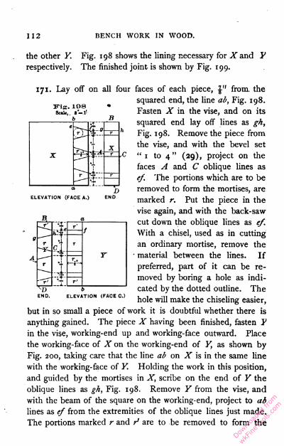
112 BENCH WORK IN WOOD.
the other Y. Fig. 198 shows the lining necessary for X and Y
respectively. The finished joint is shown by Fig. 199.
171. Lay off on all four faces of each piece, \" from, the
squared end, the line ab, Fig. 198.
Fasten X in the vise, and on its
squared end lay off lines as gk,
Fig. 198. Remove the piece from
the vise, and with the bevel set
"1 to 4" (29), project on the
faces A and C oblique lines as
ef. The portions which are to be
removed to form the mortises, are
marked r. Put the piece in the
vise again, and with the back-saw
cut down the oblique lines as ef.
With a chisel, used as in cutting
an ordinary mortise, remove the
material between the lines. If
preferred, part of it can be re
moved by boring a hole as indi
cated by the dotted outline. The
hole will make the chiseling easier,
but in so small a piece of work it is doubtful whether there is
anything gained. The piece X having been finished, fasten P
in the vise, working-end up and working-face outward. Place
the working-face of X on the working-end of Y, as shown by
Fig. 200, taking care that the line ab on X is in the same line
with the working-face of Y. Holding the work in this position,
and guided by the mortises in X, scribe on the end of Y the
oblique lines as gh, Fig. 198. Remove Y from the vise, and
with the beam of the square on the working-end, project to ab
lines as ef from the extremities of the oblique lines just made.
The portions marked r and t3 are to be removed to form the
Fig. 108Scale, lVl!
b
ELEVATION (FACE A.)D
END
r h f Tn fr'
el.
r
~rr
T.--wi--
t' r'ELEVATION (FACE 0.)_ T_
Downlo
aded
from
wkFine
Tools
.com

BENCH WORK. ii3
ELEVATION (B.)
"pins." Those on the outside marked r'.may be removed
entirely with the saw; those on the inside (r), partly with the
chisel, as in the case of the mortises in the piece X.
The joint ought to go together by light driving, and
be perfectly square on
the inside between
the working- faces. If
it is found to be satis
factory, take it apart,
apply a light coating
of glue, and drive to
gether again. When
the glue is hard, the
joint may be smoothed and squared, and
the ends of the pieces cut to the dimen
sions shown in Fig. 199.
173. It will be seen that one part of
the joint is made, and the second part is
then made to fit the first; hence, the
proportions of the first part need not be
determined with great exactness. The skilled
bench-worker usually proceeds as follows : on
the piece X (if there are several pieces, X, he
treats them all at the same time) he lays off
the lines ab and cross-lines as gh, the latter
without measuring, and then saws obliquely
without the use of lines as ef; on Fhe lays off
the lines ab and oblique lines as gh, and saws without making
lines as ef. In this way the joint is soon made, and, al
though not perfectly symmetrical, it may be well-formed and
well-fitted.
ELEVATION (A.)
P"ig. SOO
WORKING FACE-HI
rDow
nload
ed fr
om
wkFine
Tools
.com

114 BENCH WORK IN WOOD.
EXERCISE No. 12. — Lap, or Drawer, Dovetail.
The stock required is one piece X 3!" X 4" and one
piece i" X 3!" X 4",
edges jointed parallel
1 N
Fig. SOI
Scale, f-i
WismPLAN. 1 and one end of each
squared. The finished
piece is shown by Fig.
201. It will be seen
that the piece X does
not extend across the
full thickness of the
piece Y, and, consequently, the end grain
does not ap-
ELEVATION (FACE B.)pear in Eleva
tion B, Fig.
201.
ELEVATION (FACE AO I74» On Y,
Fig. 202, scribe the line ab, \"(the thickness of X) from the
working- end, and continue it
across the working-edges. Set a
gauge at £", and from the work
ing-face A gauge the line cd on
the working-end, and extend it on
the edges until it meets the ex
tended line ab, as shown by face
D, Fig. 202. From the working-
end of X, with the same gauge,
make the line ab on the two faces
A and C. Produce the remaining
lines on X, cut the mortises, and
lay off Y by X, as in the last
exercise.
Scale,soa8-1'
PLAN (FACE D.)a
M
ELEVATION (FACE A.)
ELEVATION (FADE A.)
Downlo
aded
from
wkFine
Tools
.com

BENCH WORK. "5
In cutting out around the pins ( Y), the delicacy of the work
does not demand the most delicate chisel, but one as large as
is convenient should be used. Finish the joint to the dimen
sions given by Fig. 201. .'
EXERCISE No.
Fig.
Scale,
a 03s— t
\d B 13. — Blind Dovetail.
The stock required
is two pieces, each
\" X 3I" X 4" edges
jointed parallel and
one end squared. The
finished joint is shown
by Fig. 203. The
elevation (face b.) dovetail iswholly with
in the square abed, and, consequently, no
end grain shows on any face.
PLAN.
t
175. With the square, lay off on the
working-faces and two edges of each piece
of material, Fig. 204, the lines ba, ai, and
cd, dk, and from the working-face A gauge
§1iELEVATION (FACE A.)
m
on the ends of each piece the line ef.
Fig. 304
c b
F.ig. SOB
PLAN (FACE D.)
d a
Scale, 3*—V
a I eb
d a>
PLAN.
ELEVATION (FACE A.) END.
* iELEVATION.
Downlo
aded
from
wkFine
Tools
.com
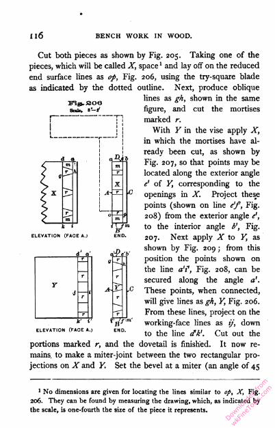
n6 BENCH WORK IN WOOD.
m;gi.soa
Sale, « —i
"Ma
Cut both pieces as shown by Fig. 205. Taking one of the
pieces, which will be called X, space 1 and lay off on the reduced
end surface lines as op, Fig. 206, using the try-square blade
as indicated by the dotted outline. Next, produce oblique
lines as gh, shown in the same
figure, and cut the mortises
marked r.
With Y in the vise apply X,
in which the mortises have al
ready been cut, as shown by
Fig. 207, so that points may be
located along the exterior angle
e' of Y, corresponding to the
openings in X. Project these
points (shown on line e'f, Fig.
208) from the exterior angle e',
to the interior angle b', Fig.
207. Next apply X to Y, as
shown by Fig. 209 ; from this
position the points shown on
the line a'f, Fig. 208, can be
secured along the angle a'.
M2-\ Vc These points, when connected,
will give lines as gh, Y, Fig. 206.
From these lines, project on the
working-face lines as ij, down
to the line dk\ Cut out the
portions marked r, and the dovetail is finished. It now re
mains, to make a miter-joint between the two rectangular pro
jections on X and Y. Set the bevel at a miter (an angle of 45
ELEVATION (FACE A.) END
'JO.
rh
r
r
r
ELEVATION fFACE A.|
1 No dimensions are given for locating the lines similar to op, X, Fig.
206. They can be found by measuring the drawing, which, as indicated by
the scale, is one-fourth the size of the piece it represents.
Downlo
aded
from
wkFine
Tools
.com

BENCH WORK. 117
degrees) and scribe the dotted line e, Fig. 205, on each piece ;
then cut to line with a chisel. When the joint has been fitted,
glue, and finish to dimensions.
ITig..308
p.' e'b' Vig. SOS
'6n-~ n
ft*'
x
r
176. If, instead of cutting out the first and last space of Y,
one-half only is cut out, as shown by Fig. 210,
the dividing line being on a miter, and, if the ytg. sl°
outside portions of X, m, m, Fig. 206, are cut <^ 7
away to a miter to correspond, the joint will
appear as a plain miter-joint, instead of that shown by
Fig. 203.
EXERCISE No. 14. — Frame and Panel (246-248).
177. Fig. 211 shows a small panel door. The frame is made
up of stiles and rails, which are fastened together by mortise-and-
tenon joints ; the spaces within the frame are filled by panels.
The lower panel is simply a thin board screwed to the back of
the frame. The upper panel is composed of narrow strips, which
are inserted in a groove made in the frame for their reception.
The front of the frame, around the lower panel, is chamfered,
and around the upper panel is beaded. It is the purpose of
this exercise to construct that portion of the door included
within the rectangle abdc.
Downlo
aded
from
wkFine
Tools
.com

I 18 BENCH WORK IN WOOD.
Three pieces of stock are required, each jointed to dimen-
Fig. 212.
178. The mortise-and-tenon joint between the stile and rail,
both in the size and position of its parts, is shown by Fig. 213.
The width of the mortise and the tenon should be equal to the
width of the f" chisel.1 It will be noticed that the lines are
so placed as to make the stile extend beyond the lower edge of
the rail. This extension, or "horn," as it is called, is for the
1 The nominal width of a chisel does not always agree with its actuaj
width.
Downlo
aded
from
wkFine
Tools
.com
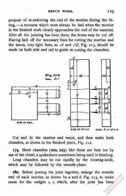
BENCH WORK. HQ
purpose of re-enforcing the end of the mortise during the fit
ting, — a recourse which must always be had when the mortise
in the finished work closely approaches the end of the material.
After all the jointing has been done, the horns may be cut off.
Having laid off the necessary lines for cutting the mortise and
the tenon, very light lines, as cd and c'd1, Fig. 213, should be
made on both stile and rail to guide in cutting the chamfers.
,Fig. 213
- — ey
-2}~
SIDE OF RAIL.
61 DE OF ST I LE. EDGE A OF ST I LE
Cut and fit the mortise and tenon, and then make both
chamfers, as shown in the finished piece, Fig. 212.
179. Short chamfers (222, 223) like these are best cut by
use of the chisel, a spokeshave sometimes being used in finishing.
Long chamfers may be cut rapidly by the drawing-knife,
which may be followed by the smooth-plane.
180. Before putting the joint together, enlarge the outside
end of each mortise, as shown by a and b, Fig. 213, to make
room for the wedges c, c, which, after the joint has been
Downlo
aded
from
wkFine
Tools
.com

i20 BENCH WORK IN WOOD.
driven together, are to be dipped in glue and driven as
indicated. This method of wedging forms a very strong
joint (250, 251).
181. Round the edge of the panel on the bottom and side,
as shown by a, Fig. 212, and fasten it to the back of the
frame by two 1" No. 8 screws — one in the rail, and one, b,
in the stile (258) .
182. In inserting screws, the outside piece (in this case the
panel) must be bored for each screw. The hole should be
sufficiently large to allow the screw to pass through easily ; and,
if the wood is hard, it must be enlarged at the top, or " coun-
terbored," to receive the head of the screw. The piece in
which the screw holds (in this case the frame), if of soft wood,
need not be bored unless there is danger that it may split, in
which case a hole should be made, in diameter about two-thirds
that of the screw. The necessity for a hole in hard wood
depends largely on the proportions of the screw. A short,
large-wired screw will stand almost any service, while a long
slender one will frequently be twisted or broken under the
strain necessary to drive it into wood which is only moder
ately hard.
Judgment must determine when the screw is driven suf
ficiently. The head must bed well into the wood ; but
there is danger that it may be forced so far as to " strip "
the thread, and that, as a consequence, the screw will not
hold (96, 98).
Never allow the screw-driver to slip from the slot of the
screw while the latter is being driven.
183. Brad-awls are useful in preparing the way for small
screws. The cutting edge should always be placed across the
grain so that the fibers will be cut, and not simply pressed apart
to close up again when the tool is withdrawn. The difference
Downlo
aded
from
wkFine
Tools
.com

BENCH WORK. 121
in effect may be seen by comparing, Fig. 214, A, which shows
a proper action, with B.
Fig. 314
EXERCISE No. 15. — Paneling.
This exercise consists in making that portion of the panel
door, Fig. 211, included within the rectangle efgh.
Fig. ais
Scale, a' l'
Downlo
aded
from
wkFine
Tools
.com

i22 BENCH WORK IN WOOD.
Three pieces of stock are required, each jointed to dimen
sions as follows : stile i£" X 2\" X 9" ; rail i£" X 2^" X 6%" ;
panel strip |" X if" X 18". The completed exercise is shown
by Fig. 215.
184. In considering the joint between the stile and rail as
shown by Fig. 216, three new features will be observed j the
groove, or " plow," which is to receive the panel, as shown at
a, Fig. 215 ; the beads ff; and the mitered corner cd, which
allows the parts to be plowed and beaded as shown, without
affecting the mortise-and-tenon joint.
Follow the dimensions, and line for the mortise and tenon as
in the preceding exercises, supposing the rail to be of the form
indicated by the dotted outline ctjc', Fig. 216, and the stile to
be of the form indicated by efd. This done, add the lines ec,
Scale, s"-l'
l 2j —;
T
{ *i
( sj".i- 1 r-TT-; 4"— ~ j
J.1 .1 a 1
t 1 ,- 1
ELEVATION.
cd, and c'd1, by means of gauge and bevel. Cut the mortise
and the tenon, after which plow the groove a.
Downlo
aded
from
wkFine
Tools
.com

BENCH WORK. i23
185. No special direction can be given for using the plow
(85), except that it is to be used from the working-edge ; but
it will be safe to practice with it on a piece of waste material
before applying it to the work.
186. Next, the beads f,f, Fig. 215, are to be formed on the
inside edge of .both rail and stile, that is, along the edges
marked b, Fig. 216. What has already been said regarding
the use of the plow, may also be said of the beading-plane
(84)-
The mitered corners are now to be formed by cutting with
the back-saw to lines already made, and then the joint between
stile and rail, fitted and wedged as
in Exercise No. 14.
The frame having been made
ready, attention may be given to
the panel. The panel strip, al
ready jointed, must be "matched"
by forming the tongue b and the
groove a, Fig. 217. This opera
tion brings into use the \" match-
ing-planes (82), which should first
be tried on a piece of waste ma
terial. The bead c, Fig. 217, is
to be made with a -fa" beading-
plane.
Cut the panel strip into lengths suitable for forming the
complete panel, Fig. 218, using either the bevel or the miter-
Downlo
aded
from
wkFine
Tools
.com
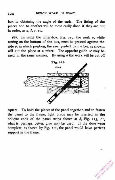
124 BENCH WORK IN WOOD.
box in obtaining the angle of the ends. The fitting of the
pieces one to another will be most easily done if they are cut
in order, as a, b, f,etc.
187. In using the miter-box, Fig. 219, the work a, while
resting on the bottom of the box, must be pressed against the
side b, in which position, the saw, guided by the box as shown,
will cut the piece at a miter. The opposite guide cc may be
used in the same manner. By using d the work will be cut off
square. To hold the pieces of the panel together, and to fasten
the panel to the frame, light brads may be inserted in the
oblique ends of the panel strips shown at b, Fig. 215, or,
what is, perhaps, better, glue may he used. If the door were
complete, as shown by Fig. 211, the panel would have perfect
support in the frame.
Downlo
aded
from
wkFine
Tools
.com
PART III.
ELEMENTS OF WOOD CONSTRUCTION.
CARPENTRY.1
188. It is the work of the carpenter to raise and inclose
the frame of a building, to construct- its floors and roofs, and
to complete all parts which give stability to the structure ; the
joiner makes the doors and windows, erects the stairs, and
provides such interior woodwork as-will finish the building as
a habitation. A single mechanic may perform almost every
kind of work required in the construction of a building, thus
eliminating this distinction of trades ; but for convenience in
classification we may imagine the work of the carpenter and
that of the joiner to be quite distinct.
It will be understood that neither carpentry nor joinery is
confined to house-building. While all bench work may properly
be classed as joinery, it involves forms and principles that are
the logical outgrowth of carpentry. For this reason, in the
following consideration of joints, there are presented, first,
those belonging to carpentry, which will include such as are
used in uniting timbers, as in a frame for a building ; and,
secondly, those belonging to joinery, which will include such
1 Tredgold's " Carpentry," and " Notes on Building Construction,"
published by Rivingtons, have furnished many of the facts presented
under Carpentry and under Joinery.
Downlo
aded
from
wkFine
Tools
.com

126 BENCH WORK IN WOOD.
as are used in joining small planks or boards. This classifica
tion cannot be rigidly adhered to, but it will serve the purpose
of the following pages.
189. Any two timbers may be united in the direction of
their length, or they may be united at an angle.
Timbers united in the direction of their length are usually
subject to compressional stress, which has a tendency to reduce
Fig. a3O Fig. 231
1—E ) E /
their length, as indicated by Fig. 220; or tensional stress,
which has a tendency to increase their length, Fig. 221; or
transverse stress, which has a tendency to bend them, Fig. 222 ;
or to two of these stresses at the same time.
190. A Timber subjected to transverse stress must always
bend. The fibers forming that surface which is convex or has a
tendency to become so (as the lower surface, A, Fig. 222) will
be subject to tensional strain, while the fibers forming the
opposite surface will be brought under compressional strain
This is shown by Fig. 223, A representing a straight timber,
and B the same timber bent. It follows, then, that somewhere
between the compressed surface and the extended surface there
will be a line which is subject to neither compressional norDownlo
aded
from
wkFine
Tools
.com
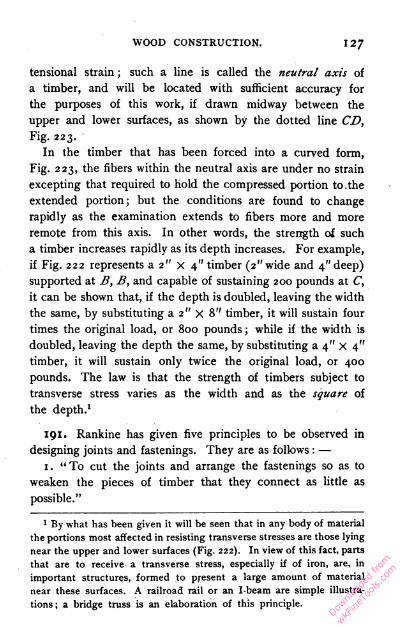
WOOD CONSTRUCTION. 127
tensional strain ; such a line is called the neutral axis of
a timber, and will be located with sufficient accuracy for
the purposes of this work, if drawn midway between the
upper and lower surfaces, as shown by the dotted line CD,
Fig. 223.
In the timber that has been forced into a curved form,
Fig. 223, the fibers within the neutral axis are under no strain
excepting that required to hold the compressed portion to. the
extended portion; but the conditions are found to change
rapidly as the examination extends to fibers more and more
remote from this axis. In other words, the strength of such
a timber increases rapidly as its depth increases. For example,
if Fig. 222 represents a 2" X 4" timber (2" wide and 4" deep)
supported at B, B, and capable of sustaining 200 pounds at C,
it can be shown that, if the depth is doubled, leaving the width
the same, by substituting a 2" X 8" timber, it will sustain four
times the original load, or 800 pounds; while if the width is
doubled, leaving the depth the same, by substituting a 4" X 4"
timber, it will sustain only twice the original load, or 400
pounds. The law is that the strength of timbers subject to
transverse stress varies as the width and as the square of
the depth.1
191. Rankine has given five principles to be observed in
designing joints and fastenings. They are as follows : —
1. "To cut the joints and arrange the fastenings so as to
weaken the pieces of timber that they connect as little as
possible."
1 By what has been given it will be seen that in any body of material
the portions most affected in resisting transverse stresses are those lying
near the upper and lower surfaces (Fig. 222). In view of this fact, parts
that are to receive a transverse stress, especially if of iron, are, in
important structures, formed to present a large amount of material
near these surfaces. A railroad rail or an I-beam are simple illustra
tions ; a bridge truss is an elaboration of this principle.
Downlo
aded
from
wkFine
Tools
.com

128 BENCH WORK IN WOOD.
2. "To place each abutting surface in a joint as nearly
as possible perpendicular to the pressure which it has to
transmit."
3. "To proportion the area of each surface to the pressure
which it has to bear, so that the timber may be safe against
injury under the heaviest load which occurs in practice, and
to form and fit every pair of such surfaces accurately, in order
to distribute the stress uniformly."
4. " To proportion the fastenings so that they may be of
equal strength with the pieces which they connect."
5. ."To place the fastenings in each piece of timber sp that
there shall be sufficient resistance to the giving way of the
joint by the fastenings shearing or crushing their way through
the timber."
Complicated forms of joints are likely to violate Rule 3.
Joints connecting Timbers in the Direction of their
Length.
192. A Lapped Joint, shown by Fig. 224, fastened either
by straps A or bolts B, is clumsy, but very strong.
193. A Fished Joint in its simplest form is shown by
Fig. 225, and is so called because of the two pieces marked A
which are known as fish-pieces or fish-plates.
vis- sas
Fish-pieces may be of either wood or iron, and may be
employed to form the fished joint shown in Fig. 225, or applied
to more complicated joints to increase their strength.Dow
nload
ed fr
om
wkFine
Tools
.com
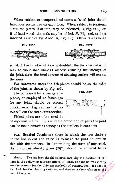
WOOD CONSTRUCTION. 129
When subject to compressional stress a fished joint should
have four plates, one on each face. When subject to tensional
stress the plates, if of iron, may be indented, A, Fig. 226 ; or,
if of hard wood, the ends may be tabled, B, Fig. 226, or keys
inserted as shown by A and B, Fig. 227. Other things being
Fie. aaa Fig. say
equal, if the number of keys is doubled, the thickness of each
may be diminished one-half without reducing the strength of
the joint, since the total amount of abutting surface will remain
the same.
For transverse stress the fish-pieces should be on the sides
of the joint, as shown by Fig. 228.
The bolts used for securing fish- sas
two will cut the same cross-section. [
Fished joints are often used in
heavy construction. By a suitable proportion of parts the joint
can be made almost as strong as the timbers it connects.
194. Scarfed Joints are those in which the two timbers
united are so cut and fitted as to make the joint uniform in
size with the timbers. In determining the form of any scarf,
the principles already given (191) should be adhered to as
Note. — The student should observe carefully the position of the
lines in the following representations of joints, so that he may clearly
see the reasons for the different methods of construction. He should
first look for the abutting surfaces, and then note their relation to the
rest of the joint.
pieces, or employed as fastenings
for any joint, should be placed
checker-wise, Fig. 228, so that no
Downlo
aded
from
wkFine
Tools
.com
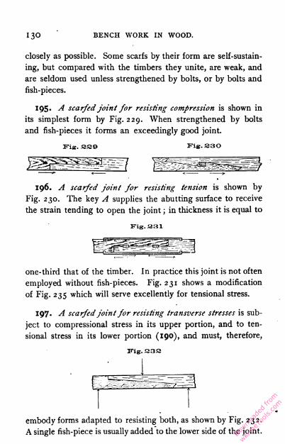
i30 BENCH WORK IN WOOD.
closely as possible. Some scarfs by their form are self-sustain
ing, but compared with the timbers they unite, are weak, and
are seldom used unless strengthened by bolts, or by bolts and
fish-pieces.
195- A scarfed joint for resisting compression is shown in
its simplest form by Fig. 229. When strengthened by bolts
and fish-pieces it forms an exceedingly good joint.
Fig. SS9 Fig. S30
196. A scarfed joint for resisting tension is shown by
Fig. 230. The key A supplies the abutting surface to receive
the strain tending to open the joint ; in thickness it is equal to
Fig. 331one-third that of the timber. In practice this joint is not often
employed without fish-pieces. Fig. 231 shows a modification
of Fig. 235 which will serve excellently for tensional stress.
197. A scarfedjoint for resisting transverse stresses is sub
ject to compressional stress in its upper portion, and to ten
sional stress in its lower portion (190), and must, therefore,
Fig. S3S
embody forms adapted to resisting both, as shown by Fig. 232.
A single fish-piece is usually added to the lower side of the joint.Downlo
aded
from
wkFine
Tools
.com
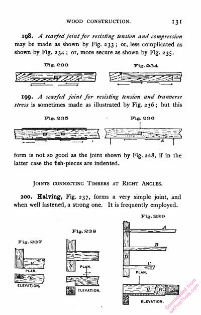
WOOD CONSTRUCTION. 131
198. A scarfedJoint for resisting tension and compression
may be made as shown by Fig. 233 ; or, less complicated as
shown by Fig. 234 ; or, more secure as shown by Fig. 235.
Fig. 333 Fig.334
199. A scarfed joint for resisting tension and tranverse
stress is sometimes made as illustrated by Fig. 236; but this
Fig. 33S • Fig. 338
form is not so good as the joint shown by Fig. 228, if in the
latter case the fish-pieces are indented.
Joints connecting Timbers at Right Angles.
200. Halving, Fig. 237, forms a very simple joint, and
when well fastened, a strong one. It is frequently employed.
Fig. 330
Downlo
aded
from
wkFine
Tools
.com
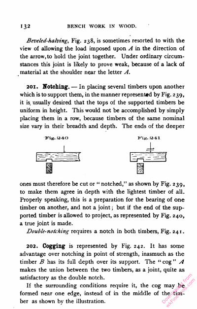
132 BENCH WORK IN WOOD.
Beveled-halving, Fig. 238, is sometimes resorted to with the
view of allowing the load imposed upon A in the direction of
the arrow, to hold the joint together. Under ordinary circum
stances this joint is likely to prove weak, because of a lack of
material at the shoulder near the letter A.
201. Notching. — In placing several timbers upon another
which is to support them, in the manner represented by Fig. 239,
it is. usually desired that the tops of the supported timbers be
uniform in height. This would not be accomplished by simply
placing them in a row, because timbers of the same nominal
size vary in their breadth and depth. The ends of the deeper
340 34-1
ones must therefore be cut or " notched," as shown by Fig. 239,
to make them agree in depth with the lightest timber of all.
Properly speaking, this is a preparation for the bearing of one
timber on another, and not a joint ; but if the end of the sup
ported timber is allowed to project, as represented by Fig. 240,
a true joint is made.
Double-notching requires a notch in both timbers, Fig. 241.
202. Cogging is represented by Fig. 242. It has some
advantage over notching in point of strength, inasmuch as the
timber B has its full depth over its support. The " cog " A
makes the union between the two timbers, as a joint, quite as
satisfactory as the double notch.
If the surrounding conditions require it, the cog may be
formed near one edge, instead of in the middle of the tim
ber as shown by the illustration.
Downlo
aded
from
wkFine
Tools
.com
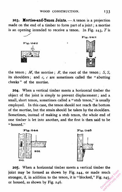
WOOD CONSTRUCTION. 133
203. Mortise-and-Tenon Joints. —- A tenon is a projection
made on the end of a timber to form part of a joint ; a mortise
is an opening intended to receive a tenon. In Fig. 243, ^is
the tenon ; M, the mortise ; R, the root of the tenon ; S, S,
its shoulders ; and c, c are sometimes called the " abutting
cheeks " of the mortise.
204. When a vertical timber meets a horizontal timber the
object of the joint is simply to prevent displacement ; and a
small, short tenon, sometimes called a " stub tenon," is usually
employed. In this case, the tenon should not reach the bottom
of the mortise, but the strain should be taken by the shoulders.
Sometimes, instead of making a stub tenon, the whole end of
one timber is let into another, and the first is then said to be
" housed."
Fig. 344 ITiK. 345
205. When a horizontal timber meets a vertical timber the
joint may be formed as shown by Fig. 244, or made much
stronger, if, in addition to the tenon, it is "blocked," Fig. 245,
or housed, as shown by Fig. 246.
Downlo
aded
from
wkFine
Tools
.com
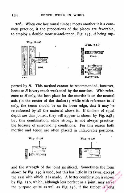
i34 BENCH WORK IN WOOD.
206. When one horizontal timber meets another it is a com
mon practice, if the proportions of the pieces are favorable,
to employ a double mortise-and-tenon, Fig. 247, A being sup-
Fig. 346
D. ELEVATION.
ported by B. This method cannot be recommended, however,
because B is very much weakened by the mortises. With refer
ence to B only, the best place for the mortise is on the neutral
axis (in the center of the timber) ; while with reference to A
only, the tenon should be on its lower edge, that it may be
re-enforced by all the material above it. If timbers of equal
depth are thus joined, they will appear as shown by Fig. 248 ;
but this combination, while strong, is not always practica
ble because of surrounding conditions. For this reason both
mortise and tenon are often placed in unfavorable positions,
Fig. 348 Fig. 348
and the strength of the joint sacrificed. Sometimes the form
shown by Fig. 249 is used, but this has little in its favor, except
the ease with which it is made. A better combination is shown
by Fig. 250, which, although less perfect as a joint, may serve
the purpose quite as well as Fig. 248, if the timber is longDownlo
aded
from
wkFine
Tools
.com
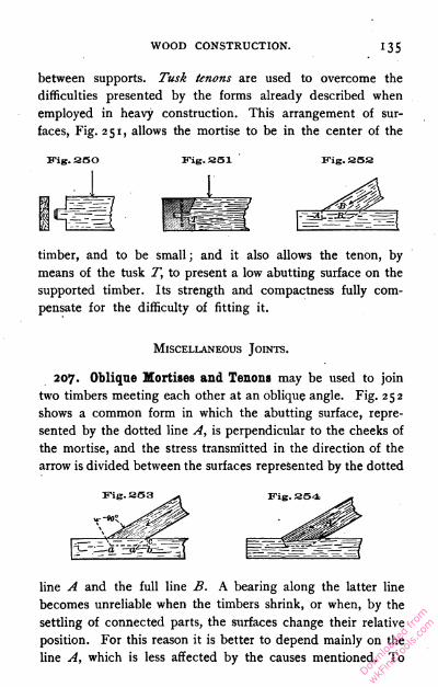
WOOD CONSTRUCTION. 135
between supports. Tusk tenons are used to overcome the
difficulties presented by the forms already described when
employed in heavy construction. This arrangement of sur
faces, Fig. 251, allows the mortise to be in the center of the
Fig. 35O Fig. 351 Fig.352
timber, and to be small ; and it also allows the tenon, by
means of the tusk T, to present a low abutting surface on the
supported timber. Its strength and compactness fully com
pensate for the difficulty of fitting it.
Miscellaneous Joints.
207. Oblique Mortises and Tenons may be used to join
two timbers meeting each other at an oblique angle. Fig. 252
shows a common form in which the abutting surface, repre
sented by the dotted line A, is perpendicular to the cheeks of
the mortise, and the stress transmitted in the direction of the
arrow is divided between the surfaces represented by the dotted
line A and the full line B. A bearing along the latter line
becomes unreliable when the timbers shrink, or when, by the
settling of connected parts, the surfaces change their relative
position. For this reason it is better to depend mainly on the
line A, which is less affected by the causes mentioned. To
Downlo
aded
from
wkFine
Tools
.com

i36 BENCH WORK IN WOOD.
take all of the stress, this line should be at right angles to the
length of the tenon-bearing timber, Fig. 253. This, however,
while apparently a well-formed joint, is not a strong one, for
the tenon, which is usually equal to but one-third the width of
Kig. aS5 Fig.S56
END. SIDE. END. SIDE.
the timber, must alone receive the thrust. To relieve the tenon
by increasing the area of the abutting surface, the end of A
may be housed, as shown by Fig. 254, or the joint may be
strengthened by bolts or straps.
The mortise for the joint shown by Fig. 253 is usually made
of the outline abc, and the triangle a'bc is not filled. This is
done because it is easier to cut down the line be than the line
a'c. There seems to be no objection to this practice.
208. A Bridle Joint is represented by Fig. 255. It pos
sesses the advantage of having its parts so exposed that any
inaccuracy in the fit is always apparent. An oblique form of
bridle joint, Fig. 256, is certainly worthy of study. The width
of the bridle, B, Fig. 255, should not exceed one-fifth the
width of the timber. Downlo
aded
from
wkFine
Tools
.com

WOOD CONSTRUCTION. 137
209. A Tie Joint is shown by Fig. 257. By the insertion
of the tie B, the timber A is prevented from falling away in
the direction indicated by the arrow. The joint illustrated by
Fig. 197 may be made to serve the same purpose.
210. A Chase Mortise is a mortise elongated as shown by
Fig. 258. Its purpose is to admit a cross-timber between two tim
bers already fixed. When the cross-timber is in place that por
tion of the mortise which is unoccupied may be filled, and the
joint thus made secure.
JOINERY.
211. The work of the joiner, unlike that of the carpenter,
is usually where it must bear the test of close examination. It
is, therefore, necessary that the several pieces of which a whole
work is formed, be united by joints that are neat in appearance,
or so made as to be hidden from sight. Such joints must be
strong even where there is apparently but little stress upon
them ; otherwise, the parts are likely to become loose from
shrinking and swelling, and to expose unsightly seams.
Some of the joints already described, while particularly
adapted to uniting timbers in carpentry, may under given
conditions be equally suitable for the smaller work in joinery.
It may also be true that some which are treated in connection
with joinery are quite as useful in carpentry. As already stated,
the classification here used only serves to fix in mind a few
general principles governing the adaptation of joints ; it cannot
be arbitrarily adhered to.
The rule in carpentry that makes the simplest form of joint
best, does not always hold in joinery, because the methods of
the joiner admit of greater accuracy, and also because the
pieces of material used are smaller, and consequently less
affected by shrinkage.
Downlo
aded
from
wkFine
Tools
.com
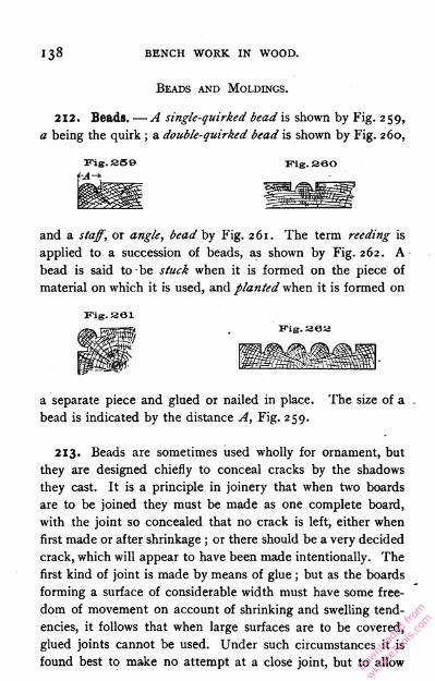
i38 BENCH WORK IN WOOD.
Beads and Moldings.
212. Beads. —A single-quirked bead is shown by Fig. 259,
a being the quirk ; a double-quirked bead is shown by Fig. 260,
ifig. sao
and a staff, or angle, bead by Fig. 261. The term reeding is
applied to a succession of beads, as shown by Fig. 262. A
bead is said to be stuck when it is formed on the piece of
material on which it is used, and planted when it is formed on
Fig. sai
Kig. sea
a separate piece and glued or nailed in place. The size of a
bead is indicated by the distance A, Fig. 259.
213. Beads are sometimes used wholly for ornament, but
they are designed chiefly to conceal cracks by the shadows
they cast. It is a principle in joinery that when two boards
are to be joined they must be made as one complete board,
with the joint so concealed that no crack is left, either when
first made or after shrinkage ; or there should be a very decided
crack, which will appear to have been made intentionally. The
first kind of joint is made by means of glue ; but as the boards
forming a surface of considerable width must have some free
dom of movement on account of shrinking and swelling tend
encies, it follows that when large surfaces are to be covered,
glued joints cannot be used. Under such circumstances it is
found best to make no attempt at a close joint, but to allowDownlo
aded
from
wkFine
Tools
.com

WOOD CONSTRUCTION. I 39
0
the pieces to shrink and swell as they may, and depend upon
beads to conceal the cracks. Thus the joint shown by Fig. 263
would seem to have been intended for a close fit ; but since it
Fig. 383 Fig. 364 Fig.SeS
ELEVATION. ELEVATION. ELEVATION.
is not, the opening is allowed to remain, and a bead applied,
as shown by Fig. 264. The crack is thus converted into a quirk
of a bead, and is not noticeable except on close inspection.
214. A chamfer is a narrow surface produced usually at
an angle of forty-five degrees with two other surfaces. Like
the bead, it may be used for ornament, or for disguising cracks
as shown by Fig. 265.
215. A stop chamfer is one which does not extend the full
length of the piece on which it is formed. See A, Fig. 212.
216. Moldings, while of the same character with beads, are
larger and often much more complex in form. They may be
stuck or planted. Among the most simple forms is the ogee,
Fig. 266, which is frequently used as a finish for the edge of
a projecting board — a table top, for example.
217. A round-nose, Fig. 267, is, perhaps, the simplest of
all, and is especially useful where a projecting board is subject
Downlo
aded
from
wkFine
Tools
.com
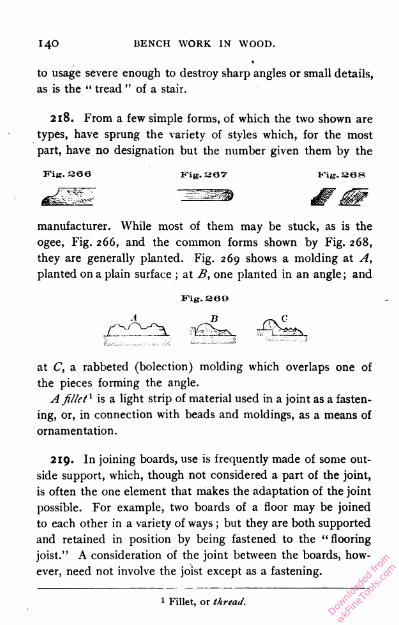
i40 BENCH WORK IN WOOD.
to usage severe enough to destroy sharp angles or small details,
as is the " tread " of a stair.
218. From a few simple forms, of which the two shown are
types, have sprung the variety of styles which, for the most
part, have no designation but the number given them by the
Fig. 366 Kig. S67 Fig.368
manufacturer. While most of them may be stuck, as is the
ogee, Fig. 266, and the common forms shown by Fig. 268,
they are generally planted. Fig. 269 shows a molding at A,
planted on a plain surface ; at B, one planted in an angle; and
at C, a rabbeted (bolection) molding which overlaps one of
the pieces forming the angle.
A fillet1 is a light strip of material used in a joint as a fasten
ing, or, in connection with beads and moldings, as a means of
ornamentation.
219. In joining boards, use is frequently made of some out
side support, which, though not considered a part of the joint,
is often the one element that makes the adaptation of the joint
possible. For example, two boards of a floor may be joined
to each other in a variety of ways ; but they are both supported
and retained in position by being fastened to the " flooring
joist." A consideration of the joint between the boards, how
ever, need not involve the joist except as a fastening.
Fig. SOB
1 Fillet, or thread.
Downlo
aded
from
wkFine
Tools
.com
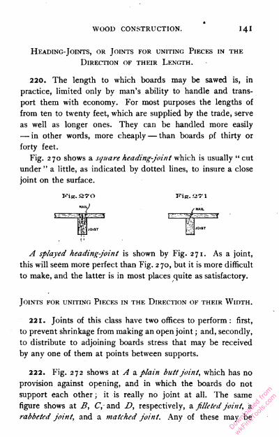
WOOD CONSTRUCTION. 141
Hkading-Joints, or Joints for uniting Pieces in the
Direction of their Length.
220. The length to which boards may be sawed is, in
practice, limited only by man's ability to handle and trans
port them with economy. For most purposes the lengths of
from ten to twenty feet, which are supplied by the trade, serve
as well as longer ones. They can be handled more easily
— in other words, more cheaply — than boards of thirty or
forty feet.
Fig. 270 shows a square heading-joint which is usually " cut
under " a little, as indicated by dotted lines, to insure a close
joint on the surface.
Vift. 370 Fis.U71
A splayed heading-joint is shown by Fig. 271. As a joint,
this will seem more perfect than Fig. 270, but it is more difficult
to make, and the latter is in most places quite as satisfactory.
Joints for uniting Pieces in the Direction of their Width.
221. Joints of this class have two offices to perform : first,
to prevent shrinkage from making an open joint ; and, secondly,
to distribute to adjoining boards stress that may be received
by any one of them at points between supports.
222. Fig. 272 shows at A a plain butt joint, which has no
provision against opening, and in which the boards do not
support each other ; it is really no joint at all. The same
figure shows at B, C,- and D, respectively, a filletcd joint, a
rabbeted joint, and a matched joint. Any of these may be
Downlo
aded
from
wkFine
Tools
.com
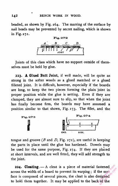
142 BENCH WORK IN WOOD.
beaded, as shown by Fig. 264. The marring of the surface by
nail heads may be prevented by secret nailing, which is shown
in Fig. 272.
A■ B C D
Joints of this class which have no support outside of them
selves must be held by glue.
223. A Glued Butt Joint, if well made, will be quite as
strong in the softer woods as a glued matched or a glued
filleted joint. It is difficult, however, especially if the boards
are long, to keep the two pieces forming the plain joint in
proper position while the glue is setting. Even if they are
clamped, they are almost sure to slip, so that when the joint
has finally become firm, the boards may have assumed a
position similar to that shown, Fig. 273. The fillet, and the
Fig. 273
I
tongue and groove (B and D, Fig. 272), are useful in keeping
the parts in place until the glue has hardened. Dowels may
be used for the same purpose, Fig. 274. If they are placed
at short intervals, and are well fitted, they will add strength to
the joint.
224. Cleating. — A cleat is a piece of material fastened
across the width of a board to prevent its warping ; if the sur
face is composed of several pieces, the cleat is also designed
to hold them together. It may be applied to the back of the
Fig. 274
Downlo
aded
from
wkFine
Tools
.com

WOOD CONSTRUCTION. 1 43
pieces, as shown by Fig. 275, or across the ends, as shown by
Fig. 276. As the grain of the cleat is at right angles to that
of the surface to which it is fastened, and since wood shrinks
Fig. are
uJ/flW I'll! 4'i
Fig. 376
ail
:;
1'
[J*-CLEAT A
|_CLEAT
CLEAT A '
116
11
mr
CUEAKB^
and swells more across the grain than with it, there is likely
to be some movement of one on the other, and the fasten
ings used to secure the cleat should be of such a nature as to
allow it. Otherwise, the edges of the board will be rigidly held,
and shrinkage will result in the formation of large cracks, by the
splitting of the board somewhere near the center. Screws are
undoubtedly the best fastenings, as they will yield, to some
degree, without becoming loosened. Nails frequently answer
every purpose, and dowels are sometimes used. Glue is un
serviceable. When it is used alone the cleats soon drop off;
and when used with other fastenings it either gives way en
tirely, or breaks at intervals, causing local cracks.
225. Side-cleating, Fig. 275, is the more effective of the two
methods, because the cleat may be larger and, for this reason,
the fastenings be applied to better advantage. But when ex
posed to view, side cleats are unsightly, and are often objec
tionable because they increase the thickness of the piece as a
whole. The proportions of the cleat may vary with the duty
expected of it. Other things being equal, a deeper cleat like
A will be more effective than B. It is more difficult, however,
Downlo
aded
from
wkFine
Tools
.com

144 BENCH WORK IN WOOD.
to put screws or other fastenings through A than through B ;
either may be fastened by screws inserted from the face of
the board.
226. End cleats are neat in appearance, and, when decided
warping tendencies are not to be overcome, do good service.
To supplement the fastenings a narrow tongue may be formed
on the board to fit a corresponding groove in the cleat, as
shown in connection with B, Fig. 276.
227. If only one surface of a cleated board is to be made
use of, —a drawing board, for example,
— the strain on the cleat may be les
sened by a succession of saw cuts on
the lower side, extending the length
of the board, as shown by Fig. 277.
By this means the warping tendency
of a seven-eighths-inch board may beSection A. B. reduced to that of a quarter-inch or
even a one-eighth-inch board.
Fig. 377
OOWIL AJoints for uniting Pieces at Right Angles.
228. Butt Joints.— A plain joint of this kind is represented
by Fig. 278. The joint may be concealed by a bead, as indi
cated by dotted lines ; and when the material is thick and it is
Fiji.
desirable to prevent an exposure of end grain as much as pos
sible, the joint may be modified, as shown by Fig. 279. This
form also may be beaded. When great strength is demandedDow
nload
ed fr
om
wkFine
Tools
.com
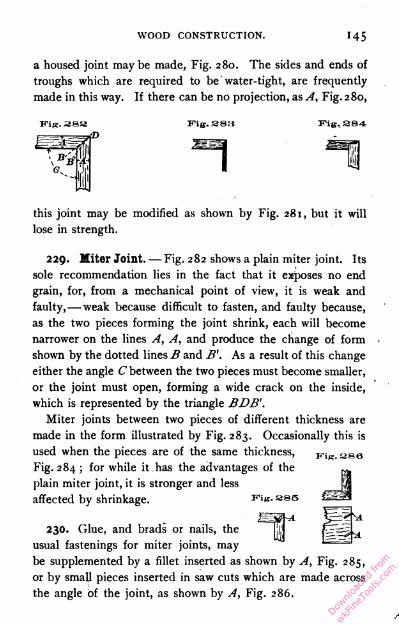
WOOD CONSTRUCTION. i45
a housed joint may be made, Fig. 280. The sides and ends of
troughs which are required to be water-tight, are frequently
made in this way. If there can be no projection, as A, Fig. 280,
Vie. as:! Fig. S84
this joint may be modified as shown by Fig. 281, but it will
lose in strength.
229. Miter Joint. — Fig. 282 shows a plain miter joint. Its
sole recommendation lies in the fact that it exposes no end
grain, for, from a mechanical point of view, it is weak and
faulty,— weak because difficult to fasten, and faulty because,
as the two pieces forming the joint shrink, each will become
narrower on the lines A, A, and produce the change of form
shown by the dotted lines B and B'. As a result of this change
either the angle C between the two pieces must become smaller,
or the joint must open, forming a wide crack on the inside,
which is represented by the triangle BDB'.
Miter joints between two pieces of different thickness are
made in the form illustrated by Fig. 283. Occasionally this is
used when the pieces are of the same thickness,
Fig. 284 ; for while it has the advantages of the
plain miter joint, it is stronger and less
affected by shrinkage. Fig. ass
230. Glue, and brads or nails, the
usual fastenings for miter joints, may
be supplemented by a fillet inserted as shown by A, Fig. 285,
or by small pieces inserted in saw cuts which are made across
the angle of the joint, as shown by A, Fig. 286.
Downlo
aded
from
wkFine
Tools
.com

i46 BENCH WORK IN WOOD.
231. Dovetail Joints have already been discussed ( 1 71-176) .
They can be made much stronger than any of the other angle
joints herein considered. The plain dovetail, Fig. 199, is
Fig. S87
sometimes objectionable because it exposes end grain, but the
checkered appearance of a well-made joint almost counter
balances this objection. In the lap-dovetail joint, however,
Fig. 201, the end grain disappears from one face, and in the
blind dovetail, Fig. 203, from both faces. The blind dovetail
is certainly all that could be desired as far as strength and
appearance are concerned, but it is difficult to make.
232. Mortise-and-Tenon Joints in joinery are different from
those employed in carpentry only in the proportions of their
parts and the accuracy with which they are fitted. When the
thickness B, Fig. 287, of the pieces joined is the same, the
thickness A of a simple tenon may vary from one-third to
one-half that of the piece on which it is formed, practice
tending toward the larger figure ; and its breadth C ought not
to exceed seven times its thickness. For the thickness given,
Fig. 388
Fig. 287 shows a tenon of the greatest breadth allowable. The
breadth is thus limited because the sides of the mortise derive
their support from the solid material at its ends, and they
become too weak for good service when the limit named is
exceeded. Again, the tenon, if too broad, will not stand the
pressure of wedging, but is likely to become distorted, thus
putting additional strain on the mortise and frequently causing
it to split. See Fig. 288. Downlo
aded
from
wkFine
Tools
.com
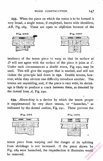
WOOD CONSTRUCTION. 147
233. When the piece on which the tenon is to be formed is
very broad, a single tenon, if employed, leaves wide shoulders,
AB, Fig. 289. These are open to objection because of the
Fig. 380 Fig.390
tendency of the tenon piece to warp so that its surface at
D will not agree with the surface of the piece it joins at C.
Under such circumstances a double tenon, Fig. 290, may be
used. This will give the support that is needed, and will not
violate the principle laid down in 232. Double tenons, how
ever, while they obviate one difficulty introduce another. The
tenons are unyielding, and, if the piece is very wide, its shrink
age is likely to produce a crack between them, as denoted by
the dotted lines A, Fig. 290.
234. Haunching is a device by which the tenon proper
is supplemented by very short tenons, or " haunches," as
indicated by the dotted outline, Fig. 291. These prevent the
Fig. 801 Fig.aOS
tenon piece from warping and the danger of its splitting
from shrinkage is not increased. If the piece shown by
Fig. 289 were haunched, the imperfection it illustrates would
be removed.
Downlo
aded
from
wkFine
Tools
.com
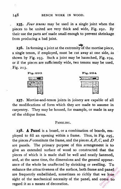
148 BENCH WORK IN WOOD.
235. Four tenons may be used in a single joint when the
pieces to be united are very thick and wide, Fig. 292. By
their use the parts are' made small enough to prevent shrinkage
from producing a bad joint.
236. In forming a joint at the extremity of the mortise piece,
a single tenon, if employed, must be cut away at one side, as
shown by Fig. 293. Such a joint may be haunched, Fig. 294,
or if the pieces are sufficiently wide, two tenons may be used,
Fig. 213.
237. Mortise-and-tenon joints in joinery are capable of all
the modifications of form which they are made to assume in
carpentry. They may be housed, for example, or made in any
of the oblique forms.
238. A Panel is a board, or a combination of boards, em
ployed to fill an opening within a frame. Thus, in Fig. 295,
the pieces Fconstitute the frame, and the pieces A,B, C, and D
are panels. The primary purpose of this arrangement is to
give an extended surface of wood so constructed that the
pieces of which it is made shall be well and neatly fastened,
and, at the same time, the dimensions and the general appear
ance of the whole be unaffected by shrinking or swelling. To
enhance the attractiveness of the surface, both frame and panel
are frequently embellished, sometimes so richly that we lose
sight of the mechanical necessity of the panel, and come to
regard it as a means of decoration.
Fig. 303 Fig. 394
Paneling.
Downlo
aded
from
wkFine
Tools
.com

WOOD CONSTRUCTION.
Fig. sea
A
Downlo
aded
from
wkFine
Tools
.com

BENCH WORK IN WOOD.
239. The Frame taken by itself is, in general, made up of
vertical and horizontal pieces united by mortise-and-tenon
joints. Vertical pieces extending the full length of any frame
are called " stiles," and horizontal pieces, " rails." Each of
these parts should be as narrow as is consistent with the degree
of strength required. The width of a rail should never be more
than twice that of the stile, which, as a rule, should not exceed
four and a half inches. A consideration of Fig. 295 will show
that, although the door is three or more feet wide, the only sur
faces whose shrinkage can affect the width are the two 4^-inch
stiles. Large surfaces are covered not by increasing the size
of the parts but by increasing their number.
A fillet e is often inserted to cover the end of the tenons,
which would otherwise show on the edge of the door.
240. The panel may be either fastened to the back of the
frame or inserted in a groove, or " plow," formed in the frame
to receive it. In either case, provision must be made for
shrinking and swelling. When fastened to the back, screws are
usually found to make a sufficiently yielding joint. When fitted
into the frame no fastening is needed beyond that derived
from its position. It must fit loosely enough to draw out on
shrinking, but not so loosely as to rattle.
In Fig. 295, A is a plain panel screwed to the back of the
frame, and the frame about it is stop-chamfered. This is,
probably, the simplest combination of frame and panel. In
common with all panels fastened in this way, it is best adapted
to work that is to be seen from one side only, as a closet door
or the permanent lining of a room.
B shows a plain panel fastened to the back of a frame which
is ornamented by a molding.
C differs from B only in being let into the frame mstead of
being screwed to the back. The reverse face c may be orna
mented by a molding in the same manner as C, or by a chamfer.Downlo
aded
from
wkFine
Tools
.com
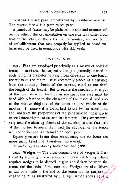
WOOD CONSTRUCTION.
D shows a raised panel embellished by a rabbeted molding.
The reverse face d is a plain raised panel.
A panel and frame may be plain on one side and ornamented
on the other ; the ornamentation on one side may differ from
that on the other, or the sides may be similar ; and any form
of embellishment that may properly be applied to board sur
faces may be used in connection with this work.
FASTENINGS.
241. Pins are employed principally as a means of holding
tenons in mortises. In carpentry one pin, generally, is used in
each joint, its diameter varying from one-sixth to one-fourth
the width of the tenon. It is commonly placed at a distance
from the abutting cheeks of the mortise, equal to one-third
the length of the tenon. But to secure the maximum strength
of the joint, its exact location in any particular case must be
fixed with reference to the character of the material, and also
to the relative thickness of the tenon and the cheeks of the
mortise. In joinery it is found best to use two or more pins,
and, whatever the proportions of the joint may be, these rarely
exceed three-eighths of an inch in diameter. They are inserted
very near the abutting cheeks of the mortise, so that that part
of the mortise between them and the shoulder of the tenon
will not shrink enough to make an open joint.
Square pins are better than round ones, but the latter are
more easily fitted and, therefore, more used.
Drawboring has already been described (168).
242. Wedges. — The most common use of wedges is illus
trated by Fig. 213 in connection with Exercise No. 14, which
requires wedges to be dipped in glue and driven between the
tenon and the ends of the mortise. Wedges are also driven
in saw cuts made in the end of the tenon for the purpose of
expanding it, as illustrated by Fig. 296, which shows at A a
Downlo
aded
from
wkFine
Tools
.com

152 BENCH WORK IN WOOD.
section of a joint before the wedges are driven, and at B a
section of the finished joint. The saw cut should extend
somewhat deeper than the point reached by the wedge. If
the tenon is broad, or if a considerable increase in breadth is
required, more than one wedge must be used. When there
are more than two, a large one should be inserted in the cen
ter and smaller ones on each side, as shown by Fig. 297, the
wedges ready for driving at A and the joint finished at B.
243. Blind-wedging is sometimes resorted to when the mor
tise does not extend through the piece. As shown by Fig. 298,
the mortise is enlarged at the bottom and the wedges started
in ; then, as the pieces are driven together, the ends of the
wedges strike against the bottom of the mortise and spread
the tenon. When driven, the tenon cannot be withdrawn.
Fig. 3DR
244. Keys differ from wedges in respect to their sides,
which are parallel or nearly so. The key may be a single
piece, as shown in the joint, Fig. 197, or, what is better,
made as two wedges, Fig. 299. These may be put in place
when in the relative position shown by A'B, after which, by
driving them upon each other, as indicated by A, B, the joint
may be tightened. The parallelism of the outside edges, which
are in contact with the joint, is always maintained.
Fig. see Fig. 297 WEDGE
Downlo
aded
from
wkFine
Tools
.com

WOOD CONSTRUCTION. i S3
245. Dowels are round wooden pins of small diameter
used to strengthen a joint. They should be dipped in glue
and driven at a tight fit into holes made for their reception.
They may be carried entirely through one piece and into the
other, Fig. 277, or inserted as shown by Fig. 274.
Dowels may be made at the bench by the plane, or they
may be turned. When planed, they will be improved in sec
tion if driven through a round hole in a piece of iron or steel.
They are supplied by the trade, of all ordinary diameters, and
in lengths of several feet, so that the consumer has but to cut
them to lengths suited to his purposes, and point them.
Shoe pegs serve well as small dowels. After being dipped in
glue they should be driven in brad-awl holes.
Whenever fastenings are required to be so placed that sub
sequent operations bring the cutting tools about them, dowels
are preferable to brads or nails, since they may be planed off
without injury to the tool.
Fig. 300Fig. 17-O
A B
246. Nails are classified according to the process by which
they are made, the material used, their form and proportions,
and the use for which they are intended. Iron and steel are
the most common materials, but when
these would be destroyed by corrosion,
copper and " galvanized " iron are used.
The forms of most importance to the
bench-worker may be classed as com
mon and finishing (or casing) nails.
Their comparative proportions are illus
trated by Figs. 170 and 300, the former
representing a common, and the latter
a finishing nail. It is evident that the
greater strength of the common nail
makes its use desirable when there is sufficient material to
receive it properly, and when the appearance of the head on
Downlo
aded
from
wkFine
Tools
.com

i54 BENCH WORK IN WOOD.
the surface is not objectionable. The finishing nail may be used
in more delicate material, and makes a smaller scar on the work.
Cut nails are so called because, in the process of manu
facture, each nail is cut from a plate of metal. The plate has
a width equal to the length of the nail, and a thickness equal
to its breadth. Generally speaking, all nails of the form shown
by Figs. 170 and 300 are cut.
Fig. 301 Wire nails, Fig. 301, are now in general use.
Their strength and tenacity are unequaled. They
are made from drawn wire in sizes varying from"
that of the smallest brad to that of the largest
spike. The terms used to describe cut nails, as
to size and form, are also applied to wire nails.
The holding power of a wire nail is often inferior
to that of a cut nail.
247. The length of nails is indicated by numbers prefixed
to the word " penny," as 6-penny, 8-penny, — terms 1 which are
now used arbitrarily, though originally they were doubtless
significant.
The length cjf nails of ordinary sizes is given as follows : —
A 3-penny nail is one inch long.
A 4-penny " one and one-fourth inches long.
A 5-penny " one and three-fourths '-' "
A 6-penny " two
A 7-penny " two and one-fourth " "
An 8-penny " two and one-half " "
A 10-penny " two and three-fourths " "
A 12-penny " three " "
A 20-penny " three and one-half " "
1 It has been suggested that they once indicated the value or price
of a given number of nails, 6-penny nails being sold at sixpence per
hundred, and 8-penny nails for eight]5ence per hundred. Another ex
planation is that penny, as here used, is a corruption of pound, 6-penny
meaning that a thousand nails weighed six pounds ; 8-penny, that a
thousand weighed eight pounds ; and so on,
Downlo
aded
from
wkFine
Tools
.com
WOOD CONSTRUCTION.
248. Brads are small finishing nails, now usually of wire.
Their size is expressed in inches and fractions of an inch, and
ranges from one-fourth of an inch to two inches.
249. Tacks are useless for fastening pieces of wood to each
other, but are indispensable when lighter material, such as cloth
or leather, is to be fastened to wood. They vary in form and
size with the particular use for which they are intended. Their
size is expressed by a number prefixed to the word "ounce." 1
The length of the more common sizes varies as follows : —
A i-ounce tack is three-sixteenths of an inch long.
A 2-ounce
A 3-ounce
A 4-ounce
A 6-ounce
An 8-ounce
A 10-ounce
one-fourth
three-eighthsseven-sixteenths
one-halfnine-sixteenths
five-eighths
250. Common Screws are either bright or blued, steel or
brass, round-headed or flat-headed.
Bright screws are finished by polishing. When blued, the
luster of the polish has been taken off by heat or an acid, and
a deep blue finish produced. Blued screws will not rust so
easily as bright screws, and in most work they look better —
considerations which apply with still greater force to the use of
brass as a material instead of steel.
Flat-headed screws, shown by Fig. 1 24, are the most com
mon. When used on finished surfaces, the heads should be
sunk below the general level and the hole above them filled.
When this is not convenient, round heads, which in the finished
work will appear above the surface, are frequently employed.
1 This expression may have once represented the weight of 1000
tacks; for example, 1000 tacks T\" long weighed one ounce, and were
therefore called " one-ounce " tacks.
Downlo
aded
from
wkFine
Tools
.com

1 56 BENCH WORK IN WOOD.
The size of screws is indicated by their length in inches or
fractions of an inch, and by the diameter of the wire forming
the body ; this diameter is expressed by a number which refers
to a "standard screw gauge." The sizes of the screw gauge
range from No. o, which represents a diameter of a little less
than a sixteenth of an inch, to No. 30, which represents a
diameter somewhat greater than seven-sixteenths of an inch.
The size of a screw two inches long and a quarter of an inch
in diameter would be written 2" X No. 15.
251. Glue is chiefly of two kinds, animal and fish. Animal
glue is a product obtained from the refuse of tanneries
(bone, horn, hoofs, and bits of hide), which is made to give
up the glutinous matter it contains by being boiled under
pressure. Fish glue is extracted from the spawn and en
trails of fish. As prepared for the market, both are generally
in the form of cakes, varying in thickness from an eighth of an
inch to very thin chips, according to the quality and character
of the glue. For bench work these are dissolved in water, and
the mixture applied hot. For convenience in dissolving the glue,
a glue-pot is used, which is an arrangement of two vessels, one
within another, the inner being for glue, the outer for water.
Heat is communicated in any convenient way to the water, and
the water in turn heats the glue. The use of the vessel of
water is to prevent the glue from burning.
Gluing. — When ready for use, the glue should be hot and
of the consistency of thin sirup. It must be applied with a
brush, in a thin, uniform coating, to both surfaces that are to
be joined, and must be well brushed into the pores of the
wood. Too much glue will prevent the pieces from coming
together in the joint. The application should be made as
quickly as possible because the glue begins to cool and set as
soon as it is taken from the pot; it will set less quickly if
the pieces to be glued are warmed. After the pieces haveDownlo
aded
from
wkFine
Tools
.com
WOOD CONSTRUCTION.
been put together, they should be rubbed to squeeze out the
surplus glue, and finally clamped in place and allowed to remain
until dry — at least twelve hours.
In gluing large surfaces, such as veneers which must be
secured to their foundations, a considerable amount of appa
ratus is required. Before the glue is applied, a heating box or
chamber, which is maintained at a high temperature by coils
of steam pipe, is used to heat the pieces to be united, and
very heavy clamps are required to squeeze the superfluous glue
from the joint. It is important to remember that while the
film of glue uniting two pieces should always be continuous,
the pieces themselves should be brought as closely together as
possible.
When end grain is to be glued it should first be sized ; that is,
coated with thin glue, in order to fill the pores of the wood,
and allowed to dry before the joint is made. Otherwise, the
glue that is put into the joint is drawn off into the grain and
becomes useless as a fastening.
An example of good gluing is found in the common lead
pencil, the wooden portion of which consists of two strips
glued together. The line of the joint can readily be traced
upon the end of the pencil, but if the work is well done, it will
be found that while the joint is a strong one, the amount of
glue between the pieces is so small as to be scarcely visible.
Liquid glues are supplied by the trade. They require no
heating and are, therefore, always ready for use.
Downlo
aded
from
wkFine
Tools
.com
PART IV.
TIMBER AND ITS PREPARATION FOR USE.
TIMBER.
252. Timber is that portion of the woody material of trees
which is serviceable for carpentry and joinery. If the trunks
of timber-bearing trees are cut into sections, they are found to
be composed of concentric cylindrical layers, separated from
each other and evidently quite distinct. One of these layers,
Fig. 302, is formed each year during the period of growth of
the tree, though false rings are sometimes produced by inter
ruptions of growth, such as are caused by drouths, or by the
destruction of foliage by caterpillars. The rings vary in thick
ness, in density, and in color, according to the rapidity of
growth, the length of the season, and other circumstances
which may change from year to year.
The outer portion of the trunk of a tree consists of a prortective layer of bark. Next to the bark is the bast, then the
cambium layer, or zone of growth, and then the sapwood,
which is usually lighter in color and less strong and dense than
the interior portions, or heartwood. As indicated by its name,
the ascent of sap takes place through the sapwood. Water
containing small quantities of minerals in solution is taken up
by the fibrous rootlets and, passing from cell to cell through
the thin walls, ascends through the outer layers of roots, trunk,Downlo
aded
from
wkFine
Tools
.com

TIMBER AND ITS PREPARATION. 159
and branches to the leaves. Here, under the influence of
light and heat, the greater part of the water is given off in the
form of vapor, and another part, with the salts it contains, is
converted into food materials. These travel downward from
leaf to branchlet, through the outer layers of the trunk to the
roots, disposing of themselves wherever they are needed along
the way, in forming new wood, new buds, and new roots. These
movements of water upward and food materials downward, take
place simultaneously, the water (sap) moving through the sap-
wood, and the food materials through the bast and inner cortex.
Fig. «oa
As the tree grows older, the cells next to the center of the
trunk gradually lose their food products, and other substances
are infiltrated into their walls and sometimes into the cell
cavities, changing the color in the majority of cases, and
increasing the density of that part of the tree ; this darker
portion is known as heartwood. The ascent of sap is greatest
in the spring, and practically ceases, in the trunk of the tree,
in winter.
Downlo
aded
from
wkFine
Tools
.com
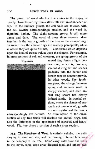
i6o BENCH WORK IN WOOD.
The growth of wood which a tree makes in the sprjng is
usually characterized by thin-walled cells and an abundance of
sap. In the summer growth the cell walls are thicker, with
the cell cavities correspondingly smaller, and the wood is,
therefore, darker. The slight autumn growth is still more
dense and dark. The wood of these three seasons taken
together is the yearly growth of the tree — the annual ring.
In some trees the annual rings are scarcely perceptible, while
in others they are quite distinct, — a difference which depends
upon the kind of tree as well as upon the climate. For example,
in cross-sections of oak and chestnut, the spring growth of the
annual ring forms a light por
ous zone, which is, however,
somewhat irregular and shades
gradually into the darker and
denser zone of summer growth.
In other woods, like South
ern pines, the change between
spring and summer wood is
sharply marked, and each an
nual ring shows two clearly
defined bands. In tropical re
gions, where the change of sea
son is not pronounced, growth
is more regular and the layers
correspondingly less definite. An examination of the cross-
section of any tree trunk will disclose the annual rings, and
also the difference in the appearance of sapwood and heart-
wood. Fig. 302 shows a portion of such a cross-section.
253. The Structure of Wood is entirely cellular, the cells
varying in form and size, and performing different functions
in the economy of the tree. Some carry water from the roots
to the leaves, some store away digested food, and others give
Fig. 303
Downlo
aded
from
wkFine
Tools
.com

TIMBER AND ITS PREPARATION. l6l
strength to the structure and hold it together. Nearly the whole
volume of wood, over ninety per cent in pine, is made up of
wood cells. Most of these are long and slender, with their
length coinciding in direction with that of the trunk or branch
they have built up ; and in many cases their tapering ends
overlap and thus increase the strength and toughness of the
stem. They are separated most readily in the direction of
their length, as is illustrated by the ease with which wood
Fig. 304
splits " with the grain." Medullary rays are thin plates
of cellular tissue which run from the pith to the bark on
all sides, strengthening and binding together the longitudinal
cells. To the unaided eye these rays appear as simple lines
in a cross-section of wood, and as glistening plates in a
longitudinal section. In the oak, the medullary rays are con
spicuous in every cross-section, while in some of the softer
Downlo
aded
from
wkFine
Tools
.com

BENCH WORK IN WOOD.
woods they can hardly be traced. Fig. 303 represents a small
portion of an annual ring of spruce, magnified one hundred
times. The vertical tubes are wood cells, and tnr is a medullary
ray part of which has been removed. The circular depressions
or pits on the wood cells are thin places in the cell walls ; they
Fig. nos
are very conspicuous in all woods of the pine family. This figure
shows also the manner in which the tapering ends of wood cells
overlap. The specimen of wood here given is from one of
the needle-leaved trees and shows a tangential section on its
right face, while Fig. 304 shows a microscopic enlargment of a
Downlo
aded
from
wkFine
Tools
.com
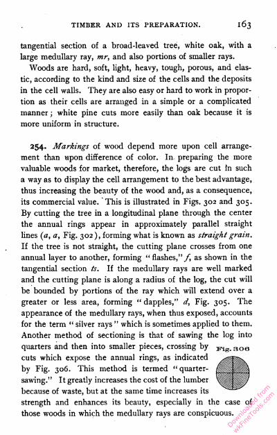
TIMBER AND ITS PREPARATION. 1 63
tangential section of a broad-leaved tree, white oak, with a
large medullary ray, mr, and also portions of smaller rays.
Woods are hard, soft, light, heavy, tough, porous, and elas
tic, according to the kind and size of the cells and the deposits
in the cell walls. They are also easy or hard to work in propor
tion as their cells are arranged in a simple or a complicated
manner ; white pine cuts more easily than oak because it is
more uniform in structure.
254. Markings of wood depend more upon cell arrange
ment than upon difference of color. In preparing the more
valuable woods for market, therefore, the logs are cut In such
a way as to display the cell arrangement to the best advantage,
thus increasing the beauty of the wood and, as a consequence,
its commercial value. This is illustrated in Figs. 302 and 305.
By cutting the tree in a longitudinal plane through the center
the annual rings appear in approximately parallel straight
lines (a, a, Fig. 302), forming what is known as straight grain.
If the tree is not straight, the cutting plane crosses from one
annual layer to another, forming " flashes,"/, as shown in the
tangential section ts. If the medullary rays are well marked
and the cutting plane is along a radius of the log, the cut will
be bounded by portions of the ray which will extend over a
greater or less area, forming " dapples," d, Fig. 305. The
appearance of the medullary rays, when thus exposed, accounts
for the term " silver rays " which is sometimes applied to them.
Another method of sectioning is that of sawing the log into
quarters and then into smaller pieces, crossing by Fis. 30ecuts which expose the annual rings, as indicated
by Fig. 306. This method is termed " quarter-
sawing." It greatly increases the cost of the lumber
because of waste, but at the same time increases its
strength and enhances its beauty, especially in the case of
those woods in which the medullary rays are conspicuous.
Downlo
aded
from
wkFine
Tools
.com

I64 BENCH WORK IN WOOD.
Beauty of grain is often developed, also, by a rotary cut
which is obtained by revolving a log against the advancing edge
of a broad knife or cutter. The result of this process is a thin,
broad, continuous ribbon of wood, which may be used as a
veneer upon the surface of inferior woods.
Crooked or irregular grain weakens timber and makes it more
difficult to work, and is, therefore, undesirable in material
which is to be used in the framing of structures ; but it has its
value in the realm of ornamentation. Every bend or twist in
the growing tree disturbs the regularity of its
Fig. 307 structure and enhances the beauty of the boards
which may sometime be cut from its trunk.
When, therefore, a wood is suitable for decora
tive purposes, its value is increased rather than
diminished by such irregularities of grain. Some
of the most common markings are knots caused
by undeveloped buds which are covered over
by the later growth of the tree. Fig. 307 shows
a "dead" knot formed by the breaking away
of a branch. The branch was a living one for
four years, as is shown by the fact that four
annual rings are united with it. There is no
union with later rings, and still later ones would
cover the knot entirely.
In woods such as mahogany, satinwood, sycamore, and ash,
figures resembling the ripple marks of the sea on fine sand, are
due to a serpentine form of the grain, the fibers being wavy in
planes perpendicular to that on which the ripple is observed,
and those parts of the wood which receive the light being the
brightest.
Markings in wood are of value in cases where a handsome
finish is required, as in furniture and cabinetwork, and in the
inside decoration of buildings. The trees that yield such
material are those which have plenty of room for growth,
Downlo
aded
from
wkFine
Tools
.com
TIMBER AND ITS PREPARATION. I65
which are exposed to winds that bend and twist, and which
have ample light and space for the development of branches.
Lumber sawed from such trees will usually contain curls,
knots, and wavy grains of great beauty.
Attention has already been called to the fact that, for
structural purposes, straight grain and freedom from knots
are desirable. These qualities are most readily found in
trees growing under forest conditions ; that is, among other
trees, where the effort of the growing tree to reach the light,
together with a process of " natural pruning " which prevents
branches from growing, results in the production of long,
straight stems.
255. The Adaptability of the various woods depends on a
variety of conditions. The carpenter and builder, who requires
a large quantity of material with the least possible outlay of
labor upon it, uses those kinds that are abundant and cheap,
that are to be had in timbers of large dimensions, that are light
to ship, easy to work, fairly stiff, and insect proof. They need
not be handsome, hard, tough, or very strong, and shrinkage
after the wood is in place is no serious objection. In order
that the material may be easily worked, it is necessary that it
be soft and reasonably free from curls and knots. The furniture
maker uses smaller quantities of material, but he expects to put
a large amount of labor upon it, and he requires a wood that
combines strength, and sometimes toughness, with beauty and
hardness,—one that takes a good polish, that is not easily
indented, and that will keep firm joints. For some purposes,
it is required that wood shall neither warp nor shrink when
in place ; it need not be very light, or soft, or insect proof,
or very cheap, or abundant in any one kind, or furnish pieces of
large dimensions. The wagon maker seeks the qualities of
toughness, strength, and hardness combined ; the carriage
builder, cooper, and shingle maker require straight-grained,
Downlo
aded
from
wkFine
Tools
.com

BENCH WORK IN WOOD.
easy-splitting woods, with the long fiber which precludes
knots ; the essentials for telegraph poles are durability, elas
ticity, and the right proportion of length to diameter; and
good railroad ties must be hard, must hold spikes firmly,, and
must resist the action of the weather.
CHARACTERISTICS OF TYPICAL TIMBER-
YIELDING TREES.
256. Classification of Trees. — There are in the United
States nearly four hundred distinct species of trees, but the
greater part of all the wood used in construction is taken
from a comparatively small number.
Trees are divided into two general classes known as exo-
gens and endogens. The former includes all trees the trunks of
which are built up by rings or layers, — the growth, therefore,
being upon the outside. Endogenous trees in
crease from within, the new wood-strands being
interspersed among the old, and causing cross-
surfaces to appear dotted, as illustrated by
Fig. 308, which represents a cross-section of the
trunk of a palm tree. Old endogenous stems
have the older and harder wood near the sur
face and the younger and softer toward the center. Examples
of this class are found in palms, yuccas, and bamboos, and
the character of their growth is well illustrated in the common
cornstalk.
257. The Exogens are the timber-yielding trees, and since
they furnish the woods useful in construction, they are the
ones of special interest to the woodworker. They are sub
divided into broad-leaved trees and needle-leaved trees, or
conifers. Most of the broad-leaved trees are deciduous ; thatDownlo
aded
from
wkFine
Tools
.com
TIMBER AND ITS PREPARATION. 167
is, they shed their foliage in the autumn of each year. The
needle-leaved trees are, almost without exception, evergreen.
Vig. 309
258. Effect of Environment on the growth of trees is such
as greatly influences their timber value. Trees which grow in
the open, quite apart from other trees, acquire a shapeliness
Downlo
aded
from
wkFine
Tools
.com
BENCH WORK IN WOOD.
and beauty which is never equaled by those which grow in
the thicket or forest, but the timber value of such trees is
decreased by the presence of limbs, which branch from all
sides of the stem, leaving but a short length of clean trunk
from which clear lumber can be made, Fig. 309. A forest
tree, on the other hand, finds light only at the top. The
shade of the trees, which crowd it on every side, prevents it
from putting out branches until it finds a level where it can
reach out into or over their tops. A forest
has in fact two floors, the first being the
ground out of which the trunks of the trees
spring, and the second, the floor of foliage
where the tops of the trees branch, and
crowd each other for room and light, and
above which the occasional tree of unusual
vigor rises and waves its lofty boughs.
Between these two floors, a distance of
from forty to more than eighty feet, extend
the straight, limbless trunks of the trees
which, like high columns, support the floor
of foliage above. These straight, smooth
trunks of the forest trees constitute the
chief source of commercial timber. Fig. 310
shows a tree of forest growth as exposed to
view by the removal of neighboring trees.
259. Broad-Leaved Woods vary greatly
in structure and, therefore, differ widely in
quality and use. In general, it may be said that they usually
contain no resins and that their density, or weight, is great;
they are usually hard and have a complex and irregular structure,
and for these reasons are difficult to work ; and they are likely
to be of irregular growth and shape, having many branches,
and, therefore, not productive of large logs or blocks which
Fig. 310
Downlo
aded
from
wkFine
Tools
.com
TIMBER AND ITS PREPARATION. 169
are free from knots. Some nail with difficulty and are in
other ways unsuitable for use in general construction, but are
better adapted to cabinetwork, the making of furniture and
implements, and any other work which requires beauty of
finish.
Ash, basswood, beech, birch, buckeye, butternut, catalpa,
cherry, chestnut, elm, gum, hackberry, hickory, holly, locust,
maple, mulberry, sassafras, sycamore, tulipwood, and walnut
are the principal American woods of the broad-leaved divi
sion. Of these the oak, ash, maple, beech, walnut, and pop
lar probably furnish the greater part of the commercial timber
which comes from trees of this class. The general appearance
of an oak, which may be accepted as a typical hard-timber
tree, is shown by Fig. 309.
260. Oak (Quercus). — The oaks, of which there are in all
more than forty varieties, produce woods which are exceed
ingly variable, but they are usually heavy, hard, tough, porous,
very strong, and of coarse texture, the sapwood whitish, the
heartwood ranging in color from a light to a reddish brown.
There are three well-marked kinds, — white, red, and live oak.
These are kept distinct in the market, the white and the red
oak being the most common.
261. White Oak (Quercus alba Linn.). — This variety of
oak is found widely distributed over the north-central and the
eastern portions of the United States. It grows from seventy-
five to one hundred feet in height and from three to six feet
in diameter. The bark has a grayish white color from which
the variety takes its name. The annual layers are well marked
and the medullary rays are broad and prominent. The wood
is hard and liable to check unless carefully seasoned. It is
durable in contact with the soil and is capable of a high
polish. It is used in shipbuilding, cooperage, cabinetmaking,
and in the framework of buildings, as well as for furniture,
Downlo
aded
from
wkFine
Tools
.com
i7° BENCH WORK IN WOOD.
agricultural implements, carriages, railway ties, and fuel. The
weight of the seasoned wood is fifty pounds per cubic foot.
It exists in large quantities and is one of the most valuable
woods in general use.
262. Red Oak (Quercus rubra Linn.) is found in Nebraska
and Kansas, and east of the Rocky Mountains ranges from
Nova Scotia to Georgia, reaching its best development in
Massachusetts. It is often brittle, and is usually of coarser tex
ture than white oak, being more porous, less durable, and even
more difficult to season. The tree grows to be from ninety to
one hundred feet in height, and from three to six feet in
diameter, and has brownish gray bark, which is smooth on the
branches. The heartwood is light brown or red, the sapwood
darker, the medullary rays few and broad. For carpentry and
for furniture making it brings about the same price with white
oak. It is used for clapboards, barrels, interior finish, chairs,
and other work of secondary importance. Its weight is forty-
five pounds per cubic foot. The distribution of the oaks is
shown by Fig. 311. Downlo
aded
from
wkFine
Tools
.com
TIMBER AND ITS PREPARATION. 171
263. Maple (Acer) wood is heavy, hard, strong, stiff, tough,
of fine texture, and often wavy-grained. It is not durable in
the ground or under exposure to the weather. Its color is a
creamy white with shades of light brown in the heartwood. It
shrinks moderately, seasons, works, and stands well, wears
smooth, and takes a fine polish. It is used for ceiling, floor
ing, paneling, for stairways and other finishing work in houses,
for ship and car construction, and for furniture. It is a good
material for shoe lasts, shoe pegs, school apparatus, wood type,
tool handles, wood carving, turnery, scroll work, and the
mechanism of pianos. The principal varieties are the sugar
maple and the silver or white maple.
264. Sugar Maple (Acer Saccharum Marsh.). — This tree
yields a sap which is made into sugar, from which fact it takes
its name, though it has various local names, as hard maple,
black maple, sugar tree, and rock maple. It is found princi
pally in the southern part of Canada and the northern part of
the United States, though its range extends as far south as
Florida and Texas. The tree grows from seventy to one
hundred feet in height and from one and one-half to four feet
in diameter. It is the hardest variety of maple known and its
wood is superior in quality.
Dry maple weighs forty-three pounds per cubic foot. Bird's-
eye, blister, and sometimes curly effects are found in this
wood.
265. Silver or White Maple (Acer dasycarpum Ehr.),
also frequently called soft maple, and locally swamp maple,
water maple, and river maple, is found in a region extending
from New Brunswick to Florida, and westward intermittently
to Dakota and the Indian Territory. Its general characteris
tics are similar to those of the sugar maple, though it is softer,
its sapwood somewhat lighter in color, and its weight less. Its
grade is somewhat inferior to that of sugar maple and its use
Downlo
aded
from
wkFine
Tools
.com
i72 BENCH WORK IN WOOD.
extends to cheaper kinds of work. White maple weighs when
seasoned thirty-two pounds per cubic foot.
266. Black Walnut (Juglans nigra Linn.). — Of the genus
Juglans there are two species, known as black walnut and
white walnut, or butternut, though the former is characterized
popularly by the name walnut. Black walnut is found in
Ontario and Florida, on the Allegheny Mountains, and west
ward intermittently to Nebraska and Texas, and also in
Fig. 3 is
California. Its distribution is well shown by Fig. 312. The
tree reaches a height of from ninety to one hundred and
twenty-five feet, and a diameter of from three to eight feet,
has an almost black bark, and makes a fine appearance,
except in some portions of the West, where it is small
and low and much-branched. It is now everywhere scarce
because of the great demand. The wood is heavy, hard,
strong, rather coarse-grained, liable to check if not carefully
seasoned, easily worked, and is durable in contact with the
soil. Its color is a chocolate brown with lightish sapwood.Downlo
aded
from
wkFine
Tools
.com
TIMBER AND ITS PREPARATION. I 73
The annual rings are obscure, the medullary rays numerous but
thin and not conspicuous. Until lately, when oak has become
its competitor, walnut has been more generally used for gun-
stocks, for all kinds of furniture, and for the interior finish of
buildings than any other North American tree. The weight of
the seasoned wood is thirty-eight pounds per cubic foot.
267. Yellow Poplar (Liriodendron Tulipifera Linn.). —
This wood is also commonly called tulip tree and whitewood.
It is found in the region extending from New England to Florida,
and westward intermittently to Michigan and Mississippi. The
tree grows to be from sixty to eighty feet in height and two
feet or more in diameter, the bark being smooth and of a gray
color, and the sapwood lighter. It is usually light, soft, stiff
but not strong, and of fine texture, with the annual rings very
obscure and the medullary rays thin and inconspicuous. The
wood shrinks considerably when drying, but seasons without
injury, does not split in nailing, and works under a tool excep
tionally well. It is one of the largest and most useful of the
broad-leaved trees of the United States. It is used for siding
and paneling, for finishing lumber in the building of houses,
cars, and ships, for the side boards and panels of wagons and
carriages, and for the manufacture of furniture, implements,
machinery, wooden pumps, wooden ware, boxes, shelving, and
drawers. Large quantities of the wood are used in the manu
facture of paper pulp. The weight of the seasoned wood is
twenty-six pounds per cubic foot.
268. Beech (Fagus ferruginea Ait.). — This wood has only
one representative on the American continent, though in dif
ferent localities it is called red beech, white beech, and ridge
beech. It is found in the region extending from Nova Scotia
to Florida, and westward intermittently to Wisconsin and Texas.
The tree grows to be from sixty to eighty feet in height and
Downlo
aded
from
wkFine
Tools
.com

174 BENCH WORK IN WOOD.
from two to four feet in diameter, but there is not an abundant
supply of the wood nor can it be obtained in pieces of very
large dimensions. Ironwood, sometimes called blue beech, is
similar to it and is sometimes confounded with it. The heart-
wood is of a reddish color with variable shades, and the sap-
wood is nearly white. The grain is close, the annual rings
obscure, and the medullary rays conspicuous. The wood is
heavy, hard, strong, works well, and takes a good polish. It is
not durable in the ground, is liable to the attacks of boring
insects, and shrinks and checks in drying. It is used for the
manufacture of lasts, handles, and furniture. The variety com
mon in European countries (sylvatica) is also used in wood
carving, carpentry, millwork, and wagon making. The weight
of the seasoned wood is forty-two pounds per cubic foot.
269. Ash (Fraxinus). —This wood occupies a place in com
merce next in importance to that of oak. In fact, ash and oak
resemble each other in that there are bands of porous spring
wood in both, though the medullary rays of ash are thinner
and are often hardly discernible. Ash is coarser and less at
tractive, but easier to work than oak. There are, in the United
States, about fifteen species of this genus. Lumbermen, how
ever, separate them into white and black ash.
270. White Ash (Fraxinus Americana Linn.) grows in the
region between Nova Scotia and Florida, and westward inter
mittently to Minnesota and Texas. The tree rises to a height
of from forty-five to ninety feet and is three or four feet in
diameter. It usually has gray or dark brown, furrowed bark, and
smooth leaves, which are white on the under side. The heart-
wood is a mottled, reddish brown, and the sapwood either white
or very light.
The wood is straight-grained, heavy, hard, strong, stiff, and
tough, but becomes brittle with age ; it is not durable in contact
with the soil, shrinks moderately, seasons with little injury,
Downlo
aded
from
wkFine
Tools
.com

TIMBER AND ITS PREPARATION. i75
takes a good polish, and is easily worked. In carpentry it is
used for finishing lumber, for stairways, and for panels. Barrels,
baskets, cars, tool handles, and hoops are made from it, as well
as wagons, carriages, farm implements, machinery, and all kinds
of furniture. This woodgrows in abundance and is one of the
most useful of the broad-leaved varieties. The weight of the
seasoned wood is thirty-nine pounds per cubic foot. The general
Fig. 313
characteristics of the other varieties of this genus are very similar
to those of white ash. The distribution of this wood is shown
by Fig. 313.
271. Needle-Leaved Woods are more uniform in their gen
eral characteristics than the broad-leaved varieties. These
characteristics are lightness, regularity of structure, obscurity
of the medullary rays, presence of resins, absence of pores in
sections, and the ease with which the wood is worked. Trees
of this class may commonly be identified by the cones, by the
Downlo
aded
from
wkFine
Tools
.com

176 BENCH WORK IN WOOD.
needle-like leaves, and by the fact that they are evergreen,
although there are a few exceptions to this characterization.
In common speech, needle-leaved tree, soft wood, conifer, and
evergreen are used as synonymous terms. These trees afford
large, straight pieces of timber and, consequently, are suitable
for carpentry and the frames of buildings, and in the United
States they furnish the bulk of lumber for purposes of con
struction. The principal varieties are cedar, cypress, fir, hem
lock, tamarack, pine, redwood, spruce, and yew. The general
appearance of a needle-leaved tree of forest growth is shown
by Fig. 310.
272. Pine (Pinus) is by far the most important of the
needle-leaved family. There are several varieties, all of which
may be classed as either hard pine or soft pine. The four
varieties — white pine, long-leaved pine, short-leaved pine, and
loblolly pine — are important in the production of lumber for
building purposes. Of these, white pine is a soft wood, while
the other three are hard woods. Pines are characterized by
long, smooth, straight, and solid trunks.
273. White Pine (Pinus Strobus Linn.) is found in the
north-central and northeastern United States, advancing north
ward into Canada, southward into Illinois, and along the Alle-
ghenies into Georgia. This species, though commonly called
white pine, is known in different localities as Weymouth pine,
soft pine, northern pine, spruce pine, and pumpkin pine. It
is distinctively a northern tree, though it is found in some
portions of the South. It grows to be from seventy-five to
one hundred and fifty feet in height, and from three to six feet
in diameter, and even larger. The wood is very soft, light,
not strong, very close, straight-grained, exceedingly easy to
work, and susceptible of a beautiful polish. The resin pas
sages are small and not numerous or conspicuous ; the annual
Downlo
aded
from
wkFine
Tools
.com
TIMBER AND ITS PREPARATION, i77
rings are obscure, and the medullary rays thin and numerous.
Its color is a very light brown, often tinged with red, and the
sapwood is nearly white. It seasons well, shrinks less than
other pines when drying, and is fairly durable. It is used in
the manufacture of matches, wooden ware, and shingles, in
cabinetmaking, for interior finish, and in carpentry, and is the
most valuable building material of the northern states. It has
existed in extensive forests, but the supply is now rapidly
diminishing and the yellow pines are to some extent taking its
place. The weight of the seasoned white pine is twenty-four
pounds per cubic foot. Its distribution is shown by Fig. 314.
274. Long-Leaved Pine (Pinus palustris Mill.) is also
known as hard pine and yellow pine, and in different local
ities has many other names. It is a native of the southern
United States, growing freely in the south-Atlantic and Gulf
states and intermittently from Virginia to Alabama, and is the
principal lumber tree of the Southeast. It grows to be from
fifty to ninety feet in height and from one to three feet in
diameter. Its distribution is shown by Fig. 314.
The annual rings are easily detected, the medullary rays are
numerous and conspicuous, and the color is light red or orange,
with the sapwood thin and nearly white. The wood is heavy,
very hard, very strong, tough, coarse-grained, and durable,
and is used for fencing, railway ties, shipbuilding, interior and
exterior finishing, and for all sorts of heavy construction. In
the United States almost the entire product of turpentine,
pitch, tar, and resin comes from this species. Commercially
it is considered the most valuable of the southern pines.
The weight of the seasoned wood is thirty-eight pounds per
cubic foot.
275. Short-Leaved Pine (Finns echinata Mill.) is called
yellow pine and hard pine, and has many other local names.
SDownlo
aded
from
wkFine
Tools
.com
i78 BENCH WORK IN WOOD.
It is found in the region from Connecticut westward to Kan
sas and Texas. The tree grows from fifty to sixty feet in
height and from two to four feet in diameter, and is erect and
of fine appearance. Its general characteristics are much like
those of the long-leaved pine, except that it is lighter and not so
strong, and its uses, also, are practically the same. The weight
of the seasoned wood is thirty-two pounds per cubic foot.
276. Loblolly Pine (Pinus Taeda Linn.).—This tree grows
in nearly the same region as the long-leaved pine and appears
naturally on land which has been abandoned, preferably
that which has been occupied by a forest. This trait gives it
the name of old-field pine. The tree grows to be from fifty
to one hundred feet in height and from two to four feet in
diameter. In color, grain, structural qualities of wood, and
representative uses it is very similar to the long-leaved pine,
Downlo
aded
from
wkFine
Tools
.com
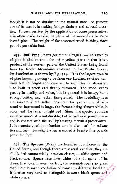
TIMBER AND ITS PREPARATION. i79
though it is not so durable in the natural state. At present
one of its uses is in making bridge timbers and railroad cross-
ties. In such service, by the application of some preservative,
it is often made to take the place of the more durable long-
leaved pine. The weight of the seasoned wood is thirty-three
pounds per cubic foot.
277- Bull Pine (Pinus ponderosa Douglas). — This species
of pine is distinct from the other yellow pines in that it is a
product of the western part of the United States, being found
from the Rocky Mountains westward to the Pacific Ocean.
Its distribution is shown by Fig. 314. It is the largest species
of pine known, growing to be from one hundred to three hun
dred feet in height and from six to eight feet in diameter.
The bark is thick and deeply furrowed. The wood varies
greatly in quality and value, but in general it is heavy, hard,
strong, brittle, and rather fine-grained. The medullary rays
are numerous but rather obscure ; the proportion of sap-
wood to heartwood is large, the former being almost white in
color and the latter a light red. Since this species contains
much sapwood, it is not durable, but is used in exposed places
and in contact with the soil by treating it with a preservative.
It is manufactured into lumber and is also used for railway
ties and fuel. Its weight when seasoned is twenty-nine pounds
per cubic foot.
278. The Spruces (Piced) are found in abundance in the
United States, and though there are several varieties, they are
all divided commercially into two classes, — white spruce and
black spruce. Spruce resembles white pine in many of its
characteristics and uses ; in fact, the resemblance is so great
that there is much confusion of names in different localities.
It is often very hard to distinguish between black spruce and
white spruce.
Downlo
aded
from
wkFine
Tools
.com

i8o BENCH WORK IN WOOD.
279. Black Spruce (Picea nigra Link ; Picea Mariana
Mill.).—This tree grows in a region between Pennsylvania and
Minnesota, and along the Allegheny Mountains to North Caro
lina, but reaches its best development in Canada. It grows
to a height of from forty to eighty feet, and a diameter of
from one to two feet, usually having a straight, conical-shaped
trunk and dark foliage. The wood is light, soft, not strong,
straight-grained, and satiny. It contains considerable resin ;
the medullary rays are few but conspicuous. The heartwood
has a light red color which is sometimes nearly white, the
sapwood being still whiter. It is used in shipbuilding, and for
piles, posts, and railway ties. In fact, in most of its uses it is a
somewhat inferior substitute for white pine. The weight of
the seasoned wood is twenty-eight pounds per cubic foot.
280. White Spruce (Picea alba Link ; Picea Canadensis
Mill.) grows in high latitudes and is found in northern United
States, Canada, Labrador, and Alaska. Its general character
istics and use are much the same as those of the black spruce,
except that the trees grow a little higher and the color of the
wood and foliage is somewhat lighter.
281. Hemlock {Tsuga), of which there are two principal
species, is light, soft, stiff, brittle, coarse-grained, and inclined
to splinter, and the limits of sapwood and heartwood are not
well defined. The wood has a- reddish gray color, is free from
resiii ducts, is moderately durable, shrinks and warps consider
ably, wears rough, and retains nails firmly. The bark, which
is red on the outside, is used for tanning leather.
282. Eastern Hemlock {Tsuga Canadensis Carr.) is found
in eastern and central Canada, where it has its best develop
ment, and extends southward to North Carolina and Tennessee.
It is a handsome tree with a straight trunk, and grows to be
eighty or more feet in height and two or three feet in diameter.
Downlo
aded
from
wkFine
Tools
.com
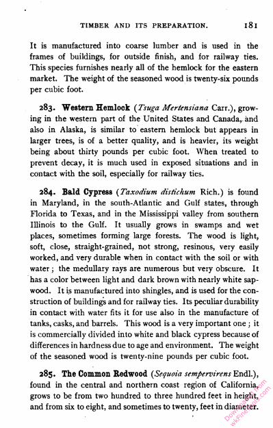
TIMBER AND ITS PREPARATION. l8l
It is manufactured into coarse lumber and is used in the
frames of buildings, for outside finish, and for railway ties.
This species furnishes nearly all of the hemlock for the eastern
market. The weight of the seasoned wood is twenty-six pounds
per cubic foot.
283. Western Hemlock (Tsuga Mertensiana Carr.), grow
ing in the western part of the United States and Canada, and
also in Alaska, is similar to eastern hemlock but appears in
larger trees, is of a better quality, and is heavier, its weight
being about thirty pounds per cubic foot. When treated to
prevent decay, it is much used in exposed situations and in
contact with the soil, especially for railway ties.
284. Bald Cypress (Taxodium distichum Rich.) is found
in Maryland, in the south-Atlantic and Gulf states, through
Florida to Texas, and in the Mississippi valley from southern
Illinois to the Gulf. It usually grows in swamps and wet
places, sometimes forming large forests. The wood is light,
soft, close, straight-grained, not strong, resinous, very easily
worked, and very durable when in contact with the soil or with
water ; the medullary rays are numerous but very obscure. It
has a color between light and dark brown with nearly white sap-
wood. It is manufactured into shingles, and is used for the con
struction of buildings and for railway ties. Its peculiar durability
in contact with water fits it for use also in the manufacture of
tanks, casks, and barrels. This wood is a very important one ; it
is commercially divided into white and black cypress because of
differences in hardness due to age and environment. The weight
of the seasoned wood is twenty-nine pounds per cubic foot.
285. The Common Eedwood (Sequoia sempervirens Endl.),
found in the central and northern coast region of California,
grows to be from two hundred to three hundred feet in height,
and from six to eight, and sometimes to twenty, feet in diameter.
Downlo
aded
from
wkFine
Tools
.com
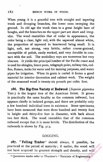
182 BENCH WORK IN WOOD.
When young it is a graceful tree with straight and tapering
trunk and drooping branches, the lower ones sweeping the
ground. In old age the trunk rises to a great height bare of
boughs, and the branches on the upper part are short and irreg
ular. The wood resembles that of cedar in appearance, the
color being a clear, light red, with the sapwood almost white,
the proportion of sapwood to heartwood being small. It is
light, soft, not strong, very brittle, rather coarse-grained,
susceptible of polish, easily worked, and very durable in con
tact with the soil. The medullary rays are numerous but very
obscure. It yields the principal lumber of the Pacific coast and
is used for shingles, fence posts, telegraph poles, railway ties, cof
fins, flumes, tanks for water and for tanning purposes, and water
pipes for irrigation. When its grain is curled it forms a good
material for interior decoration and cabinet work. The weight
of the seasoned wood is twenty-six pounds per cubic foot.
286. The Big-Tree Variety of Redwood (Sequoia gigantea
Torr.) is the largest tree of the American forest. It grows
in practically the same locality as the common redwood, but
appears chiefly in isolated groups, and there are probably only
a few hundred individual trees in existence. Some specimens
have been measured that were three hundred and twenty feet
in height and thirty-five feet in diameter, with bark about
two feet thick. The wood resembles that of the common
redwood except that it is more brittle. The distribution of the
redwoods is shown by Fig. 313.
LOGGING.
287. "Felling Timber1 should always, if possible, be
practiced at the period of maturity ; if earlier, the wood will
not have acquired its greatest strength and density, and will
1 Quotation marks refer to Thurston's " Materials of Engineering."
Downlo
aded
from
wkFine
Tools
.com
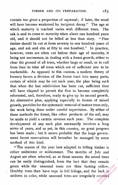
TIMBER AND ITS PREPARATION. i 83
contain too great a proportion of sapwood ; if later, the wood
will have become weakened by incipient decay." The age at
which maturity is reached varies with different trees. The
oak is said to come to maturity when about one hundred years
old, and it should not be felled at less than sixty. " Pine
timber should be cut at from seventy to one hundred years of
age, and ash and elm at fifty to one hundred." In practice,
however, trees are often cut before their age of maturity, it
being not uncommon, in dealing with a forest growth, either to
clear the ground of all trees, whether large or small, or to cull
from time to time all trees which are of sufficient size to be
marketable. As opposed to this custom, a modern theory of
forestry favors a division of the forest tract into many parts,
certain of which may be cut each year, the plan being such
that when the last subdivision has been cut, sufficient time
will have elapsed to permit the first to become completely
reforested, and, therefore, ready to give up its second growth.
An alternative plan, applying especially to forests of mixed
growth, provides for the systematic removal of mature trees only,
the work being done under careful supervision. By either of
these methods the forest, like other products of the soil, may
be made to yield a certain revenue each year. The complete
development of any such plan necessarily involves a long
series of years, and as yet, in this country, no great progress
has been made ; but it seems probable that the large govern
ment forest reservations will hereafter be managed by some
method of this kind.
"The season of the year best adapted to felling timber is
either midwinter or midsummer. The months of July and
August are often selected, as at those seasons the sound trees
can be easily distinguished, from the fact that they remain
green while the unsound trees are then turning yellow.
Healthy trees then have tops in full foliage, and the bark is
uniform in color, while unsound trees are irregularly covered
Downlo
aded
from
wkFine
Tools
.com

BENCH WORK JN WOOD.
with leaves of varying color, having a rougher and often a
loosened bark, and decaying limbs." After felling, "the trunk
should be immediately stripped of its bark, and when heart-
wood only is wanted, the sapwood removed as soon as possible."
This gives the wood a chance to dry quickly and at the same
time prevents deterioration by the action of worms and decay.
" The bark is often removed from trees in spring and the
felling deferred till autumn or winter." This, ordinarily, can
be done only with small trees, but it is a good course to pursue
when possible.
In the actual felling of the trees, the method has been from
time immemorial to use the ax, and very small trees are still
cut in this way ; for larger trees the saw is used in connec
tion with the ax. The cut is usually made high enough above
the ground to avoid the very hard grain, the heavy sap, and in
some cases the accumulation of pitch at the base of the tree.
For large trees this height is from six to eight feet above the
ground. Notches are first cut on opposite sides of the tree,
into which are inserted boards on which the workmen stand.
After the direction of the fall is decided, an " undercut " is
made with the ax at right angles to it and on the side next
to the fall, extending into the tree a distance equal to one-
third of its diameter. The saw is then applied to the opposite
side, and when the kerf has been advanced nearly through to
the undercut, wedges are driven into the saw-cut so as to
bring the tree down in the proper place. In this way the
possibility of doing injury to other trees may be avoided.
Machines have been invented to take the place of the method
described, but they are not in general use.
After the tree has been felled it is sawed into logs of suitable
length. Barkers then chop or strip away the bark, either from
the whole surface of the logs or from the side on which they
are to be dragged, and clear away the underbrush to form a
way along which they may be moved. Downlo
aded
from
wkFine
Tools
.com

TIMBER AND ITS PREPARATION. 185
288. Transportation of the logs to the sawmill is effected
in different ways, which depend upon the locality and sur
rounding conditions. In all regions except the West, where
redwood and other very large trees must be handled, the
common practice is to drag the logs by means of horses or
oxen to the nearest stream or railroad. For this purpose
tramways are made by placing logs of similar size parallel to
each other across the way, at intervals of from four to eight
feet. The logs are moved to the tramway from the places
where they have fallen, by rolling if the distance is very short,
or if the ground is inclined in the proper direction ; otherwise,
they are pulled into position by a horse. A number of logs
are then fastened together by chains and a team of horses
or oxen drags them along the tramway, which leads either to a
logging railroad or to a stream or pond. In the latter case the
logs are placed within the high-water zone at a time when the
water is low, and when the spring freshets cause them to float
they are guided to the sawmill, which is usually built near a pond
or stream. This is the cheapest and most common method of
transportation. In the northern part of the United States and
in Canada, the common practice has been to carry on the log
ging in the winter time, and in the spring to float the logs on
the water courses to the mill, which does not run during the
winter season. Here, instead of a tramway, an "ice run"
is made by cutting a shallow trench in the ground and pour
ing water upon it. When it is frozen, the logs are dragged
over it by a team. This forms an efficient, and compared
with the tramway a very inexpensive, means of transporta
tion. The methods here described are those common in the
eastern part of the United States, and in fact in all places
where the operations are not extensive. In the West, where
bulky material must be handled, and the work is pursued upon
a large scale, the tendency is to rely upon machinery for
moving the logs. Chains are secured to them by means of
Downlo
aded
from
wkFine
Tools
.com
BENCH WORK IN WOOD.
grappling hooks, and they are drawn from the place of fall to the
tramway, or " skid-road," by the action of a " yarding " engine,
which is similar in form to engines used in hoisting ; on the
tramway another engine pulls them to the nearest railroad or
water way. Where the course is down a mountain side, the logs
may be slid down a suitably constructed chute.
289. Sawmills contain all the machinery necessary for
converting logs into lumber. As has been stated, they are
usually situated upon the shore of some stream or pond, in
order that they may be easily reached from the lumber camp.
The process of making lumber from logs is effected by means
of a saw, fixed in position, to which the log is fed. The log
is mounted upon a carriage, which is arranged to reciprocate,
advancing toward the saw for the cutting stroke and return
ing after the cut is made. Various means are employed for
propelling the carriage, which in a large mill is made to move
with great rapidity. The two classes of machinery used in
general sawmilling are the circular sawmill and the band saw
mill. The former is the older and, for general purposes, is still
more used. The objections to the circular saw arise from the
width of its kerf, which causes a great waste of material, the
loss in sawdust for some cuts being one-fifth the whole amount
of wood used.
The band saw has much to recommend it, especially in the
reduced width of the kerf, which, ordinarily, is but little more
than half that of a circular saw of the same power and capacity ;
hence, the amount of material wasted in the form of sawdust is
less. The band saw is more expensive and not so portable as
the circular saw, and is therefore more suitable for large and
permanent establishments.
290. The Process of Sawing. — The log is drawn from the
mill pond by means of a carrier, or log jack, operated by the
power of the mill. Arriving at the proper point, by suitableDownlo
aded
from
wkFine
Tools
.com
TIMBER AND ITS PREPARATION. 1 87
mechanism the log is rolled upon skids in a position near the
carriage, and then by the movement of a single lever is thrown
upon the carriage and fastened. As the carriage goes forward
toward the saw, the first outside piece, or slab, is cut. On the
return of the carriage, mechanism operates to move it sidewise
by an amount sufficient to allow the log to clear the saw. The
log is turned a quarter of a revolution, after which another
slab is cut. In this way four slabs are taken off, leaving the
log nearly square in section, though the thickness of the slabs
is not sufficient to allow the meeting of the plane surfaces pro
duced by their removal. The squared log is then sawed into
planks or boards. From the carriage, these land on revolving
rolls, which carry them to the " edger," in which they are
trimmed so as to give the widest possible planks with parallel
edges. From the edger, the lumber moves on rollers or chain
conveyors to the " trimmer," where it is made to pass saws
which are set to cut the pieces to standard lengths. It is then
thrown on a platform, from which it is trucked to the yards for
storage or to the cars for shipment.
When the slabs leave the saw they are conveyed by revolv
ing rolls to the "slasher"; in this machine they are cut into
lengths, usually of four feet, conveyed to the lath machine,
sawed up into laths, and bound into bundles. All short pieces
are sorted by hand, and some go to the shingle machine,
while the rest are converted into stove wood. The sawdust
and fine refuse help feed the furnaces of the mill, and the
coarse stuff that cannot be used, even for fuel, is burned to
get it out of the way.
291. Milling. — The processes of the sawmill are followed
by those of the finishing mill, in which the rough-sawed lum
ber is planed to a smooth surface and is matched, beaded, or
molded, to make it serviceable for floors, wainscoting, and
inside finish. Because of the prominence of the planing
Downlo
aded
from
wkFine
Tools
.com
i88 BENCH WORK IN WOOD.
machine in these mills, such establishments are often called
planing mills. Planing mills may be combined with the saw
mills, or located at any convenient point between them and
the centers where lumber is consumed. As finished lumber
is lighter and less bulky than the rough-sawed, the operation
of a finishing mill in connection with the sawmill effects a
saving in freight when the lumber is shipped. On the other
hand, as the planing mill usually deals with seasoned lumber,
and as better judgment as to finishing can be exercised when
the exact nature of the requirements is known, it is often most
convenient to have the finishing mill at the point of consump
tion. It is for this reason that planing mills are located in cities
which are far distant from sawmills.
The machines of the finishing mill are numerous. There
are planers which dress the rough plank to a smooth surface
and to a uniform thickness ; matching machines which cut
the tongue and groove on the edges of boards which are to
be used for flooring and similar work ; molding machines for
giving finish to the edges of planks or for producing strips of
curved section ; saws for ripping and saws for cross-cutting,
and a variety of other and more highly specialized machines,
such as those for boring, paneling, and sand-papering. A full
description of these does not fall within the purpose of this
discussion, but such machinery is so common that most stu
dents can easily gain an opportunity to inspect its action.
292. Water in Timber. — As has been explained, wood is
composed of cells of different forms and of different functions
with reference to the life of the tree. These contain more or less
water, which may occur in three conditions: (1) it forms the
greater part of the contents of the living cells ; (2) it saturates
the walls of all cells ; and (3) it partly fills the cavities of the
lifeless cells, fibers, and vessels. In some cases the water in
growing timber makes more than half the weight of the wood.Downlo
aded
from
wkFine
Tools
.com

TIMBER AND ITS PREPARATION. 1 89
Sapwood contains more water than heartwood ; hence there
is more water in the upper portion of a tree trunk than in its
lower portion, more in limbs than in trunk, and most in the
roots. Different trees of the same kind differ in the amount
of water they contain, thrifty trees having more than stunted
ones, and young ones more than old, while the moisture in
the wood of all trees varies with the season of the year. The
popular idea that trees contain more water in summer than in
winter, however, is not always correct, tests recently made by
the United States Bureau of Forestry showing that the greatest
weight of certain trees is in the winter.
293. The Process of Seasoning consists in driving out of
green wood, either by natural or artificial means, a consider
able portion of the water contained in the walls and cavities
of its cells. Seasoning thins the walls of the cells and makes
the wood appear more porous. The rate at which it will sea
son, or dry, depends upon the kind of timber, the size of the
piece, the "part of the trunk from which it is taken, and
the character of its exposure to drying influences ; pine, for
example, dries faster than oak, small boards faster than large
ones, and sapwood faster than heartwood.
• Wood newly cut from a living tree, when exposed to ordi
nary atmospheric conditions, gradually dries, and in so doing
changes its weight and dimensions. Green lumber, therefore,
is unstable with reference to these qualities and is not service
able for many purposes until it has been seasoned. All lumber
designed for the manufacture of furniture, cabinetwork, and
machinery should be thoroughly seasoned before it is used.
The method employed in seasoning must be such that the
timber will not only dry, but will also be preserved from injury
during the process. Some of the harmful effects due to
improper ways of seasoning are the formation of cracks, or
" checking," and a loss of strength caused by injury to the
wood structure ; these must be taken into account in deciding
Downlo
aded
from
wkFine
Tools
.com
190 BENCH WORK. IN WOOD.
upon the method to be used. Those most common are air
seasoning, steam seasoning, water seasoning, boiling in oil,
and kiln-drying.
294. Air Seasoning is the cheapest and probably the best of
the methods mentioned, although it is slow and must be care
fully conducted or there will be much injury by decay and by
checking. It consists in piling the lumber out of doors where
the air may circulate freely about it. Under these conditions
the moisture is given off and the solid constituents of the sap
gradually harden and become incapable of further change ;
the lumber is then regarded as seasoned. Air drying demands
the exercise of considerable care. If green lumber is piled
without proper air spaces, it is sure to decay; while, on the
other hand, if exposed to sun and wind, the moisture in the
outer portions of each piece thus exposed evaporates fasterDownlo
aded
from
wkFine
Tools
.com
TIMBER AND ItS PREPARATION. I9I
than that in the inner portions, and that in the ends faster
than that at the middle, with the result that shrinkage proceeds
unequally and cracks are formed. Both decay and checking
may be prevented by piling the timber properly and protect
ing it from the sun and rain. It should be so placed that the
air may circulate freely, not only on all sides of the piles but
also about each piece. Fig. 315 shows a pile of railroad ties
as arranged for seasoning. Sawed lumber may be piled in a
similar way, and with material of uniform dimensions the pile
may be carried to a considerable height. The time required
to air-dry lumber depends upon the size of the pieces, a longer
time being allowed for large sticks than for smaller ones.
Sometimes lumber which has been piled but a few months is
regarded as seasoned, and for some purposes it may be safely
used, but the drying is only partial. For complete air-drying
from two. to four years are required.
295. Steam Drying is employed when it is desired to
season boards quickly, or when it becomes necessary to soften
wood in large pieces for the purpose of bending it, as, for
instance, in shipbuilding and furniture making. As a season
ing process it is objectionable, because the high temperature
required is likely to injure the wood structure to such an extent
as to decrease the strength of the material. The process con
sists in exposing the wood to an atmosphere of steam under
considerable pressure. The steam enters the cells of the wood
and dissolves the sap, leaving water in its place ; when the
water is dried out, the wood is left well seasoned. The soften
ing of the fibers by the steam during this process, and the
uniform conditions of heat overcome all tendency toward
checking, which is so likely to occur in air seasoning. The
steaming process occupies but a few hours.
296. Water Seasoning is accomplished by allowing the tim
ber to remain for a considerable time in water. By this means
Downlo
aded
from
wkFine
Tools
.com

192 BENCH WORK IN WOOD.
the sap is dissolved away and replaced by water, which evapo
rates rapidly when the timber is piled for drying. Timber sea
soned in this way usually shrinks uniformly, exhibiting but slight
disposition to check. Logs which are designed for the spars of
ships are invariably water-seasoned. They are usually stored
in water, with the bark on, for many months, and are thus kept
in a soft and workable condition until such time as they may
be removed for finishing.
297. Kiln Drying is a common method of artificial season
ing. It requires far less time than the processes already men
tioned, and, with the exception of air-drying, is the one to
which most lumber is subjected. Dry-kilns are to be found in
connection with nearly all sawmills and planing mills, and
also with those manufacturing establishments which consume
large quantities of wood, such as furniture and car factories.
Air-seasoned lumber, designed for inside finish, when received
at the sawmill is often piled for a few days in the kiln to remove
moisture which it may have gathered from the atmosphere.
298. Kilns, of which there are many forms, are large
structures fitted with machinery for circulating dry, hot air
about the lumber that is placed in them. The lumber is piled
upon light trucks, which are run into the kiln upon lines of
track. The doors are then closed and steam is turned into
the coils of pipe by which the air is heated. Moisture-laden
air escapes through a chimney and is replaced by dry air taken
in below the pipes. In operation, the green lumber is intro
duced into that end of the kiln from which the moist and
heated air is discharged, and cars containing the seasoned
lumber are removed from the other. By this arrangement the
cars progress through the kiln, the dryest air coming in con
tact with the dryest lumber, and that which is most heavily
laden with moisture, with the greenest lumber. This course
Downlo
aded
from
wkFine
Tools
.com

TIMBER AND ITS PREPARATION. 193
prevents too great rapidity in the process of seasoning. For
seasoning green lumber, kilns require about one week for each
one-inch thickness of material. Lumber seasoned by air-drying,
and designed for inside work, can be made sufficiently dry to
avoid all chance of further shrinkage, if placed in the kiln from
forty to sixty hours for each inch in thickness. In general, more
time is required for hard woods than for soft, and, usually, the
former must be seasoned at lower temperatures than those which
may be employed with the latter. In any case, the temperature
is limited by the tendency of the wood to check ; for if the
drying process is forced too rapidly, the lumber will be injured.
299. Shrinkage in timber occurs whenever it loses mois
ture. In the process of seasoning, shrinkage may reduce the
width and thickness of a timber fully eight per cent, but it has
little effect on its length. Wood cannot be seasoned so well
that it will not shrink whenever the surrounding dryness is
increased. It also has a tendency to shrink after having its
surface removed, as in finishing by use of a plane. This is due
to the reopening of the pores, which in the fibers of the old
surface had become closed by contraction ; in this way new
passages are furnished for the escape of moisture.
300. Swelling occurs in timber whenever it absorbs mois
ture. Most woods give up moisture more readily than they
receive it ; therefore, a timber is less likely to swell when
transferred from a dry atmosphere to a moist one than to
shrink when the conditions are reversed. A slight variation,
however, in the amount of surrounding moisture is sufficient
to produce a perceptible change in the dimensions of a piece
of wood. Paint upon all exposed surfaces is some protection
against such changes, but it will not serve entirely to suppress
them. As a rule, the softer a wood is, the more readily it
shrinks and swells.
Downlo
aded
from
wkFine
Tools
.com
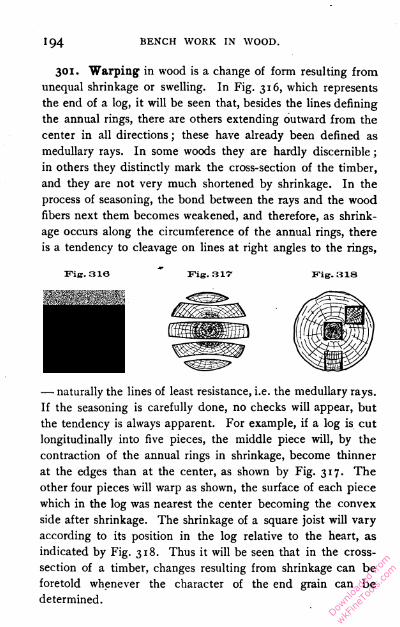
194 BENCH WORK IN WOOD.
301. Warping in wood is a change of form resulting from
unequal shrinkage or swelling. In Fig. 316, which represents
the end of a log, it will be seen that, besides the lines defining
the annual rings, there are others extending outward from the
center in all directions ; these have already been defined as
medullary rays. In some woods they are hardly discernible ;
in others they distinctly mark the cross-section of the timber,
and they are not very much shortened by shrinkage. In the
process of seasoning, the bond between the rays and the wood
fibers next them becomes weakened, and therefore, as shrink
age occurs along the circumference of the annual rings, there
is a tendency to cleavage on lines at right angles to the rings,
Fig. 316 Fig. 317 Fig. 318
— naturally the lines of least resistance, i.e. the medullary rays.
If the seasoning is carefully done, no checks will appear, but
the tendency is always apparent. For example, if a log is cut
longitudinally into five pieces, the middle piece will, by the
contraction of the annual rings in shrinkage, become thinner
at the edges than at the center, as shown by Fig. 317. The
other four pieces will warp as shown, the surface of each piece
which in the log was nearest the center becoming the convex
side after shrinkage. The shrinkage of a square joist will vary
according to its position in the log relative to the heart, as
indicated by Fig. 318. Thus it will be seen that in the cross-
section of a timber, changes resulting from shrinkage can be
foretold whenever the character of the end grain can be
determined.
Downlo
aded
from
wkFine
Tools
.com

TIMBER AND ITS PREPARATION. i95
Timbers also warp in the direction of their length. When
not due to the subjection of one part to dryness or dampness,
to the exclusion of other parts, this can be traced to uneven-
ness in the grain, which exposes a greater number of fiber
ends in one part of a surface than in another. The more fiber
ends there are on a surface, the more readily moisture will
pass into or out of the wood, and the more pronounced
will be the local shrinkage or swelling, and consequent warp
ing. For example, suppose Fig. 319 to represent the edge of
a board having the grain as° ° Fig. 318shown. Moisture will escape B Amost readily from the surfaces
marked A and A'. The con
traction of the surfaces A and
A' will force the board into the shape shown by the dotted
line. The most fruitful cause of warping, however, is unequal
exposure. One side of a board may be exposed to the sun
while the other is not ; the side exposed will be found concave
both in length and breadth. Heat from a stove or dampness
from the ground are common causes of warping. If a board
newly planed on all its faces is left flat on the bench, it will
after a time be found concave in its upper surface, — a result
due to the greater exposure of the upper surface as compared
with the lower, which remained in contact with the bench.
A piece which has reasonably straight grain, and which has
been planed all over, should be left on its edge or end.
Pieces of irregular form, that are required to be made into
shape accurately, are best prepared when roughly cut nearly to
the required dimensions, and allowed ample time to shrink and
warp before being finished exactly to size.
302. Decay in Wood is caused by the growth upon it of
fungi, which send down little food-seeking threads in all direc
tions into the wood, consuming the cell walls and their contents,
Downlo
aded
from
wkFine
Tools
.com

196 BENCH WORK IN WOOD.
and thus producing a disintegration and change of structure
which is called rot, or decay. In order to grow, the fungi
must have air, organic food materials, heat, and abundance of
moisture ; the moisture must not amount to immersion, how
ever, for too much water excludes the air and the fungi cannot
live for want of oxygen. Fungus growth is checked by cold and
killed by temperatures above 150° F., as well as by the applica
tion of certain chemicals to the wood. Perfectly seasoned
wood is not likely to rot, especially if it has good ventilation
and its surfaces of contact are well protected.
303. Timber Preservation is effected by filling the pores
with some fluid which destroys and prevents fungus growth, and
thus protects the wood from decay. Some woods, such as oak,
resist the attacks of fungi, and therefore do not rot quickly even
under unfavorable conditions. For this reason, only woods of this
kind were formerly used in work which was exposed to moisture,
as railway ties, bridge timbers, and fence posts. Of late, how
ever, such timber has become very scarce and costly, and much
attention is now given to artificial methods of preservation which
will give durability to cheaper and otherwise inferior timber.
By " inferior timber " is meant those soft, pdrous woods
which are especially liable to decay. By treating with a pre
servative, however, they are rendered durable, and red oak may
thus be made to take the place of white oak, and loblolly pine,
fir, and hemlock may be used for pine in places where resist
ance to decay is the chief requirement. The preservative treat
ment never increases the strength of a timber or its resistance
to abrasion, but, on the contrary, slightly weakens it ; for many
purposes, however, the ultimate strength of timber is of far less
importance than its durability. The requisite property of the
preserving fluid is that it will destroy and prevent the growth
of fungi, and for this purpose corrosive sublimate, tar oil, creo
sote, and zinc chloral are most used.Dow
nload
ed fr
om
wkFine
Tools
.com
TIMBER AND ITS PREPARATION. 197
The manner of applying the fluid depends upon the quantity
of wood to be treated. If the quantity is small, the preserva
tive may be applied with a brush, or the wood may be dipped
into it. If large quantities of lumber are to be treated, exten
sive plants are equipped for doing the work. The purpose in
all cases is to fill the pores of the wood with the fluid. As a
first step, the wood must be thoroughly seasoned in order that
its porosity and permeability may be as high as possible. If
the wood is absolutely dry, it will take up considerable quanti
ties of the preservative, though a high degree of penetration
is not often secured without the use of pressure. A typical
process is described in the next paragraph.
304. Creosoting. — The apparatus employed consists of one
or more heavy metallic cylinders having end doors which open
to the full size of the cross-section of the cylinder, and which
are made to close steam-tight. A track extends through the
cylinder, upon which runs a truck or car carrying the material
to be treated. Pumps and other accessory apparatus are in
pipe connection with the cylinder.
The timber to be treated is loaded on a truck and run into
the cylinder, after which the doors are securely closed. Steam
under considerable pressure is then admitted to the cylinder,
and this heats the timber and supplies moisture to fill the
pores of the wood and pressure to force it in, thus augmenting
its porosity. This accomplished, the steam is shut off and a
vacuum pump is employed to reduce the pressure within the
cylinder to as low a point as possible, with the result that the
moisture forced into the wood, having served its purpose in
opening the pores, is now drawn out. The liquid creosote is
then introduced into the cylinder and under an increase of
pressure the timber expands and the liquid penetrates far
beyond the surface of the material. Pieces which are not more
than eight or ten inches across are penetrated to their center.
Downlo
aded
from
wkFine
Tools
.com
i98 BENCH WORK IN WOOD.
After the pressure is withdrawn, the surplus liquid is drawn off,
the doors are opened, and the wood is removed. The process
as described is subject to several modifications.
It is usually unnecessary to treat wood which is designed
for the interior of buildings, the process being chiefly valuable
for such materials as come in contact with the ground or are
used about the water.
STRENGTH OF TIMBER.
305. The Strength of Timber is measured by its resistance
to yielding under the influence of external force applied in
any form. Timbers may be so located with reference to the
load they sustain as to be strained in tension, or in compres
sion, or in shear, or by bending ; and in each case the maxi
mum resistance which can be offered by a piece of wood will
have a different value. The maximum resistance also depends
upon the direction of the grain relative to the direction in
which the load is applied. In general, knotty and cross-grained
wood is not so strong as clear and straight-grained pieces of
the same material. Large timbers usually contain more imper
fections in grain than small ones which might be cut from the
larger bulk, and, hence, large timbers are likely to be relatively
weaker than small ones. In general, the heavier woods are
the stronger.
306. Strength in Tension is measured by the resistance
which is offered to a force drawing in the direction of length.
In a piece of wood, this is the sum of the resistances of all the
separate fibers making up the cross-section. Long-leaved, yel
low pine and Washington fir will withstand about 12,000
pounds for each square inch of cross-section, while oak, Cana
dian white pine, and red fir withstand about 10,000 pounds,
and the more common woods, such as white pine, NorwayDownlo
aded
from
wkFine
Tools
.com

TIMBER AND ITS PREPARATION. 199
pine, spruce, hemlock, cypress, and chestnut, from 6000 to
gooo pounds. These values are remarkably large when one
considers the lightness of the materials involved.
307. Strength in Compression is the resistance offered to
a force which tends to reduce the dimension of a material
in the direction in which the force is applied. Columns which
stand upon a foundation or base of any sort, and bear a load
upon the top, are in compression. In this case the individual
fibers act as so many hollow columns firmly bound together.
Failure under compression occurs when the fibers, by sepa
rating into small bodies and sliding over each other, cease to
act as a solid mass. This action is obviously assisted by the
presence of the smallest knot or the slightest irregularity in
grain. When tested in the form of short columns in which the
grain runs lengthwise, the common woods withstand loads in
compression of from 5000 to 8000 pounds per square inch of
cross-section.
308. Strength in Shear. — A pin which holds a tenon in
its mortise (Fig. 191) must resist shear when a force is applied
to draw the tenon out of the mortise. Similarly, that portion
of the tenon which is immediately beyond the pin is, under
the condition stated, in shear. The shear upon the pin is
across the grain, while that upon the tenon is with the grain.
Again, in the case cited, the pin is said to be in double shear,
since in giving way it would need to yield at two points in
its length, while the tenon is in single shear. The resistance
of wood to shear is much less than that to tension or com
pression. Assuming the stress to fall on a piece one square
inch in section, the resistance to shear is greatest in white
oak, for which the value across the grain is 2000 pounds and
with the grain about 800 pounds. In other woods the resist
ance to shear across the grain is from 600 to 1400 pounds,
and with the grain from 350 to 600 pounds.Dow
nload
ed fr
om
wkFine
Tools
.com
200 BENCH WORK IN WOOD.
309. Strength under Transverse Loads is shown by resist
ance to forces which tend to bend the piece. Closely allied
to the question of strength under the conditions stated, is that
of stiffness, which is often quite as important as that of strength.
A green stick is only about two-thirds as stiff as one that is
dry. Heavy pine is stiffer than light pine. Wood from the
butt of a tree is usually stiffer than that from the upper part
of the trunk. In all full-grown pine trees the heartwood is
stiffer than the sapwood, but in young pines, and also in
young, second-growth hard woods, the sapwood is stiffer. It
is the sapwood of second-growth hickory that is prized for
carriage spokes and tool handles. The load which can be with
stood by a timber subjected to a bending force varies directly
as its width, as the square of its depth, and inversely as the
length of the span. For example, a timber 5 inches deep
and 4 inches wide is twice as strong as one which is 5 inches
deep and 2 inches wide ; while one which is 2 inches wide and
10 inches deep is four times as strong as one which is 2 inches
wide and 5 inches deep. Again, a timber which rests on sup
ports 16 feet apart will carry but half the load which may be
sustained by a similar timber which rests on supports 8 feet
apart. A consideration of numerical values is difficult unless
aided by mathematical preparation. Students who are inter
ested should seek to master the theory of beams as presented
in texts dealing with the strength of materials.
Downlo
aded
from
wkFine
Tools
.com

Downlo
aded
from
wkFine
Tools
.com