bell-cutter dredger 300 24...
TRANSCRIPT
Belldredgingpumps
3
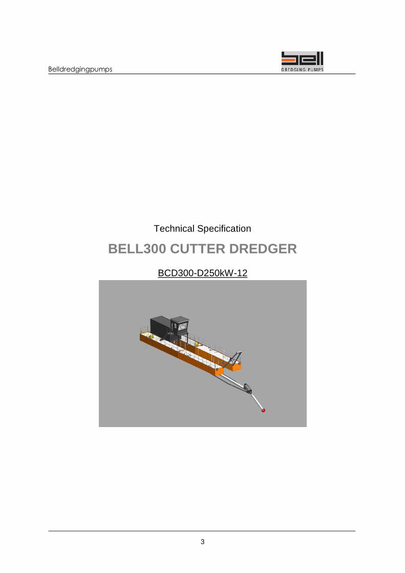
Technical Specification
BELL300 CUTTER DREDGER
BCD300-D250kW-12

Belldredgingpumps
4
BELL DREDGING PUMPS Rijdersstraat 76 NL-1735GE ‘t Veld Tel: +31 (0)6 53 38 78 45 [email protected] http://www. belldredgingpumps.com

Belldredgingpumps
5
CONTENTS
CONTENTS ..........................................................................................................................................5
1 GENERAL .......................................................................................................................................6
1.1 DREDGER IN GENERAL ...................................................................................................6 1.2 SPECIFICATIONS ..............................................................................................................6
2 ENGINE ROOM ...............................................................................................................................7
2.1 DIMENSIONS .....................................................................................................................7 2.2 INSTALLATIONS ................................................................................................................7
3 CONTROL ROOM ...........................................................................................................................8
2.1 DIMENSIONS .....................................................................................................................8
4 CUTTER LADDER...........................................................................................................................8
4.1 GENERAL ...........................................................................................................................8 4.2 SPECIFICATIONS ..............................................................................................................8 4.3 THRUSTER (OPTIONAL) ....................................................................................................8
5 CHRISTMAS TREE .........................................................................................................................9
5.1 GENERAL ................................................... 9FOUT! BLADWIJZER NIET GEDEFINIEERD. 5.2 SPECIFICATIONS ........................................ FOUT! BLADWIJZER NIET GEDEFINIEERD.
6 WINCHES ........................................................................................................................................9
6.1 GENERAL ...........................................................................................................................9 6.2 SPECIFICATIONS ..............................................................................................................9
7 HYDRAULICS ............................................................................................................................... 10
7.1 SPECIFICATIONS ............................................................................................................ 10 7.2 FUNCTIONS ..................................................................................................................... 10
8 ELECTRICAL SYSTEM ................................................................................................................. 10
9 SPECIAL DETAILS........................................................................................................................ 11
9.1 SURFACE PREPARATION .............................................................................................. 11 9.2 REGULATIONS / CERTIFICATION .................................................................................. 11 9.3 DOCUMENTATION .......................................................................................................... 11 9.4 INSTALLATION ................................................................................................................ 11 9.5 SPARE PARTS & CONSUMABLES ................................................................................. 11

Belldredgingpumps
6
1 GENERAL 1.1 Dredger in General The cutter dredger has 2 floating bodies positioned like a catamaran and an engine room in the middle on top. This engine room is above the water table and underneath the pump ladder is installed. On both sides are 2 welded floaters with water tide compartments or ballast tanks. On the floaters are bollards, hoist points, removable railing, frames used for winches or other constructions. The container used as an engine room contains the diesel engine, hydraulics and other equipment needed, above the engine room is the control room situated. This separate wheel house / control room reduces noise and vibrations coming from the dredger. This comfortable space gives a good view around and on the dredger. The ladder is situated in the middle of the dredger under the engine room and hinges on stern. On the front side of the ladder is the submersible BELL pump mounted containing the cutter head or water jet suction head. The delivery pipe coming from the BELL pump is mounted on the ladder and leafs the dredger on stern side. To position the dredger there are mooring winches and/or spuds installed. 1.2 Specifications Total length 34.0 [m ] Total width 6.5 [m ] Total height (excl. spuds) 7.5 [m ] Total weight (without fluids) 48.000 [kg] Steel construction (sea water coated) 36.000 [kg] Floater width 1.8 [m ] Floater length 23.0 [m ] Hull-height 1.2 [m ] Water draft-depth- max 0.75 [m ] Floater compartments 12 [st ] Ballast compartments 4 [st ] Ballast 4500 [Kg ] Fuel tank (diesel) 1000 [ Ltr ]

Belldredgingpumps
7
2 ENGINE ROOM 2.1 Dimensions 20ft High Cube Container (lxbxh) 6,1 x 2,4 x 2,9 [m ] Pump ladder total (lxbxh) 34 x 2,0 x 1,8 [m ] 2.2 Installations Pump Dredging pump BELL 300 [Type ] Pump suction diameter ø 300 [mm ] Pump pressure diameter ø 300 [mm ] Pump Volume capacity (mixture) 1800 [m3/h ] Pump drive motor pressure 250 [Bar] Pump drive motor flow 225 [Ltr/min] Engine Engine (Caterpillar, John Deere, Deutz or else) industrial [Type ] Engine Power 350 (460) [kW (hp) ] Engine revolutions 1800 [rpm ] Flywheel housing SAE1 Flywheel size 14 [inch ] Generator Generator open Industrial [Type ] Power 20 [kVA ] Revolutions 1500 [rpm ] Fuel tank (24 operation hours at 75% load) 120 [Ltr ] Weight 600 [Kg ] Volt 3 faze 400 [Volt ] Volt 1 faze 230 [Volt ] Frequency 50 [Hertz ] Hydraulics See Chapter Hydraulics

Belldredgingpumps
8
3 CONTROL ROOM
The control room / wheel house is made from steel and situated above and in front of the engine room. There are 4 windows and 1 steel door mounted in the walls. The control room can be reached by a ladder. In the control room we have a comfortable seat and a control desk with servo handles, manometers, joysticks and optional a suction control, sonar system, camera’s, etc.. Installed lights inside room give sufficient light for operations and on top of the roof is a work light. In the On the control room is an optional sunroof situated and / or an Air-co installed. 2.1 Dimensions Control room (lxbxh) 2,5 x 2,2 x 2,6 [m ] Options Sunroof (lxbxh) 2,6 x 2,6 x 0,2 [m ] AC-unit 800 [m3/h ]
4 CUTTER LADDER
4.1 General The basic ladder construction is build out of steel tubes mounted a BELL pump on the front side. On this BELL pump a cutter or water jet can be attached. This gives you the needed flexibility when the material changes. This way your advantage is not only an submersible pump for better performance, but you can easily change your dredger based on the solid material you need to dredge. On the ladder are the delivery pipe, water jet pipe and hydraulic hoses mounted for easy maintenance. Behind the ladder hinge is connector to attach the floating delivery line. The ladder and dredge pump will be hoisted by a winch from the control room. 4.2 Specifications Ladder Length 34,0 [m ] Cutter head diameter 900 [mm ] Cutter head driven power 45 (60) [kW (hp) ] Suction pipe diameter (removable) 300 [mm ] Suction construction length in front of the pump 5,0 [m] 4.3 Thruster (Optional) This thruster is mounded on the dredger stern and gets his water flow from the dredge pump by connecting the delivery hose in the hinge to the jet-thruster. The thrust nozzle can rotate hydraulicly in an azimuth way and the flow is regulated by water valve ND300 how is driven by hydraulic cylinder. Thrust force 25,0 [kg ]
Belldredgingpumps
9
5 Christmas Tree 5.1 General The Christmas tree is a tube construction how combines 3x winches to keep one position by pulling the steel cables into 3 different directions. This tube construction is the center point of the dredger swing. The 2 other mooring winches sweep de cutter unit from left to right. 5.2 Specifications Christmas tree diameter 350 [mm ] construction length 1,5 [m ] Hoisting force 3x 20 [kn ] Cable speed per min 3,5 [m/min ]
6 WINCHES 6.1 General The cutter dredger is installed with 3 winches, 2 mooring winches and 1 ladder winch. 6.2 Specifications Mooring winch (side wire) Cable diameter 14 [mm ] Cable Length 100 [m ] Winch Force 25 [kN ] Winch speed 12 [m/min ] Ladder winch Cable diameter 14 [mm ] Cable Length 50 [m ] Winch Force 25 [kN ] Winch speed 12 [m/min ] Spud winch Cable diameter 14 [mm ] Cable Length 20 [m ] Winch Force 20 [kN ] Winch speed 3.5 [m/min ] Anchor boom winch (Optional) Cable diameter 14 [mm ] Cable Length 50 [m ] Winch Force 10 [kN ] Winch speed 3.5 [m/min ]

Belldredgingpumps
10
7 HYDRAULICS 7.1 Specifications Hydraulic dredge pump capacity 680 [L/min] Hydraulic pump capacity auxiliaries 150 [L/min] Oil tank capacity 400 [Ltr] Max hydraulic oil pressure 260 [Bar] PVG valves controlled by Servo levers 8 [Functions] Servo function cutter head (or water jet pump) 1 [Function] Hydraulic system cooler, water 115 [kW] 7.2 Functions All functions on the cutter dredger are hydraulic. The engine drives two pumps, one pump is a 75cc hydraulic pump which gives oil to the manifold and the another pump is a 250cc and gives oil to the BELL dredge pump. The different function are:
• Dredge pump Detent proportional lever, zero – max. • Cutter head Detent Servo Lever in position 1 • Mooring winches (2x) Spring return Servo Lever • Ladder hoist winch (1x) Spring return Servo Lever • Spuds (2x) Spring return Servo Lever • Auxiliary Detent Servo Lever in position 1
8 ELECTRICAL SYSTEM The electrical system is powered by a generator (20kVA). The electrical system will be feeding lights and a AC-unit. The emergency button is placed at the control unit in the control room.

Belldredgingpumps
11
9 SPECIAL DETAILS 9.1 Surface preparation The steel construction is blasted where needed and is treated with a primer coat layer with total thickness of 45µm, The primer layer will be covered with a topcoat, thickness 45µm. All construction above water draft get the Colour RAL1007 (Yellow). The pontoons and ladder will be painted Black. Other colours are available on request. Purchase components already provided with a final surface treatment will not be repainted and normally will keep their original surface preparation. 9.2 Regulations / Certification The general CE regulations are used as guideline. For practical reasons deviations are possible. Safety doc’s : Norm UDC 002 / NEN-EN 5509
: CE-machine guidelines, European safety regulations 2006/42/EC. In case it is necessary to follow other regulations or laws, this should be expressed prior to the design phase. 9.3 Documentation As documentation two hardcopies and a digital copy on CD are provided. The documentation contains:
- operator and maintenance instructions - electrical scheme - hydraulic scheme - spare parts lists
9.4 Installation The Cutter dredger will be pre-assembled in the Netherlands, partly tested in working condition and made ready for transportation. Location for final assembling will be at your job-site. Add extra cost we will send s service technician to install the machine and to train the people on the job-site. 9.5 Spare parts & consumables All major common spare parts are delivered from European well know suppliers. These can be ordered as mentioned in the spare part list, manual or drawing (Exploded view). The regular consumables are at our stock and specials have a delivery time. This products will be packed carefully to prevent it from water or cold.