behavior of urm infill walls - … · behavior of urm infill walls strengthened with frp bars ......
TRANSCRIPT
BEHAVIOR OF URM INFILL WALLS STRENGTHENED WITH FRP BARS
J. Gustavo Tumialan1, Angel San Bartolome2 Tong Li3 and Antonio Nanni3
1Simpson Gumpertz & Heger Inc., Waltham, MA 02453, USA – email:[email protected] 2 Pontificia Universidad Católica del Perú, Lima 32, Peru – email: [email protected] 3Center for Infrastructure Engineering Studies (CIES), University of Missouri, Rolla, USA Rolla, MO 65409-710 - email: [email protected] and [email protected]
Abstract Unreinforced masonry walls (URM) are prone to failure when subjected to in-plane and out-of-plane loads caused by high wind pressures or earthquakes. Recent earthquakes have shown that the development of effective and affordable strategies for strengthening of masonry is an urgent need. In this context, fiber reinforced polymer (FRP) materials offer viable solutions to guard against or lessen the effects of overloading. This paper presents the test results of four specimens corresponding to a larger investigation program dealing with the in-plane behavior of URM infill concrete walls strengthened with FRP bars. The full-scale specimens, three walls surrounded by a reinforced concrete (RC) frame and a stand alone RC frame, were subjected to in-plane and out-of-plane loading. The results indicated that FRP strengthened specimens can reach lateral drifts of 0.7% without losing lateral carrying capacity, and, that for this drift level, the degradation of lateral stiffness in the strengthened walls does not implicate degradation of lateral carrying capacity. Also, that flexural strengthening would not be required to walls that have drifts of up to 0.7%. 1. Introduction Unreinforced masonry (URM) buildings represent a large part of the building inventory around the world. Recent earthquakes have shown that performance of URM walls has not been adequate. Fiber reinforced polymer (FRP) composites in the form of laminates or bars can provide viable solutions for the strengthening of URM walls subjected to overloading. In addition to their mechanical properties, advantages of FRP composites include lower installation costs, improved corrosion resistance, on-site flexibility of use, and minimum changes in the member size after repair. Previous investigations have demonstrated that shear capacities of URM walls can be remarkably increased by the use of FRP composites [1], [2], [3]. However, for the case of masonry infill panels, the interaction with the structural reinforced concrete (RC) surrounding frame has not been considered. Neglecting this interaction can lead to overestimating the infill wall capacity. Testing under load conditions close to those found in a real structure and considering the interaction of masonry and surrounding structural elements will aid the development of more realistic design recommendations. Depending on the design considerations, the infill walls may or may not resist lateral loads. In order to simplify the design, the potential interaction between the infill walls and the structural frame is ordinarily ignored. This assumption is valid only if the infill is not in contact with the
surrounding frame. Conversely, if the infill is in contact with the frame, ignoring the contribution of the masonry infill walls does not represent a conservative design. In this case, the presence of the infill walls can lead to stiffening of the frames and thereby cause a redistribution of lateral loads in the building plan. The increase in stiffness of the frame can attract higher lateral loads than those expected according to the design. This may cause failure of the infill wall and subsequent overstressing of the frame. This paper presents the test results of three infill masonry walls with RC frames and one stand-alone RC frame, part of a larger investigation program on the behavior of infill masonry walls strengthened by the technique called FRP structural repointing. This technique consists of placing FRP bars in the bed joints to improve the wall shear capacity. The experimental program comprises a sequence of three types of tests: • Part I deals with the testing of the specimens subjected to in-plane cyclic loading. This part
was completed when the specimens reached a lateral drift of 0.7% the height of the story. This level of drift was selected based on the recommendations provided by the acceptance criteria of FEMA 356 for infill walls [4].
• Part II deals with the moving of the specimens to a shake table where they were subjected to out-of-plane accelerations. These tests were performed to observe and quantify the out-of-plane stability of the walls after they have experienced damage.
• Part III deals with retesting under in-plane monotonic loading. This time the specimens were loaded until failure.
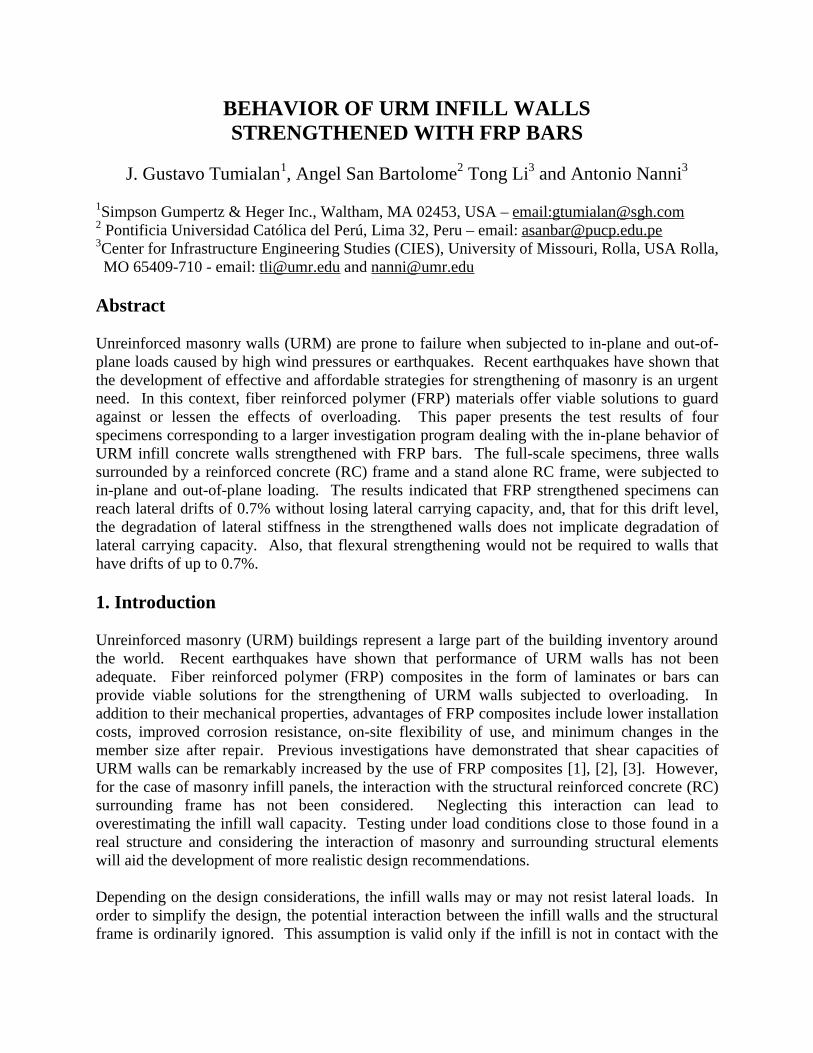
The objectives of this investigation are to evaluate the in-plane behavior of infill masonry walls strengthened with FRP bars and to develop recommendations for the strengthening of URM infill walls with FRP bars. 2. Overview of the Experimental Program 2.1. Test Specimens The infill walls were built with concrete masonry blocks following a running bond pattern. The dimensions of the infill masonry walls were 2.60 m long and 2.40 m high. The RC frames consisted of columns and a beam with cross sections of 30× 30 cm. The longitudinal reinforcement in the columns consisted of 6 bars of 19 mm diameter; the transverse reinforcement was 9.5 mm diameter. Details of the longitudinal and transverse reinforcement are presented in Figure 1. The RC frame was designed to have sufficient ductility; in this way, the behavior of the lateral force resisting system would be controlled by the infill masonry wall and not by the frame. The test specimens were built on a base beam, which was fixed to the floor of the laboratory during testing. All the infill walls were built by a qualified mason to not introduce additional variables, such as handwork and different mortar workability that may arise from the construction of masonry. The purpose of testing the stand-alone RC frame, RC-F, was to determine its stiffness and capacity, and, therefore, to assess the change in behavior of the lateral force resisting system due to the presence of the masonry infill. The infill wall in specimen IM1 was not strengthened. The infill wall in specimen IM2 was strengthened with 6.25 mm-diameter GFRP bars at every
horizontal joint with bars terminated at 10 cm. from the columns. The strengthening configuration of the infill in specimen IM3 was similar to that of IM2, but in this case the GFRP bars were anchored to the column ns. Full anchoring of the bars to the columns will be preferable. For this investigation it was decided to limit the embedment to 10 mm given the hardness of concrete and position of internal reinforcement. Exceeding the 20 mm concrete cover depth may have damaged the longitudinal steel reinforcement in the columns. The infill walls in IM1, IM2 and IM3 were integrated to the surrounding RC frame by placing mortar in the joints RC frame- infill wall. For that reason, this kind of infill walls is commonly termed as “shear infill”. Table 1 summarizes the test matrix.
240
30
48.5
5
35
50
35
240
10
10
30 503050 220
5320
20 20
50 50260
6 # 6[] # 3, 1 @ 5, 5 @ 10, r @ 20
[] 2 # 330
4 # 6[] # 3, 1 @ 5, 5 @ 10, r @ 20
[]1@5,4@10 [] #3, 6@10, r@20 6 # 6
4 # 64 [] # 3
column
beam
column
base beam
PVC 2"
240
30
48.5
55
35
50
35
240240
10
10
30 503050 220
55320
20 20
50 50260
6 # 6[] # 3, 1 @ 5, 5 @ 10, r @ 20
[] 2 # 330
4 # 6[] # 3, 1 @ 5, 5 @ 10, r @ 20
[]1@5,4@10 [] #3, 6@10, r@20 6 # 6
4 # 64 [] # 3
column
beam
column
base beam
PVC 2"
Figure 1. Dimensions and Reinforcement of RC Frame (in cm)
Table 1. Test Matrix
Specimen Description RC-F Frame without Infill Wall
IM1 Unstrengthened Infill Wall
IM2 6.25 mm-diam. GFRP bars every horizontal joints (not anchored to frame)
IM3 6.25 mm-diam. GFRP bars every horizontal Joints (anchored to frame) 2.2. Materials Tests performed on masonry prisms (ASTM E447) showed a compressive strength equal to 6.4 MPa. The RC members were reinforced with steel bars of 19 mm and 9.5 mm. The yield strength in both sizes was found to be 429 MPa. Tests on standard concrete cylinders indicated that the compressive strength of concrete was 24.8 MPa.
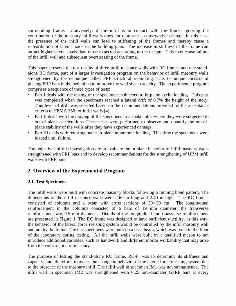
GFRP bars with nominal diameters of 6.25 mm were used. The 6.25 mm- diameter GFRP bars had a tensile strength of 827 MPa and modulus of elasticity of 40.7 MPa. These GFRP bars were embedded into an epoxy-based paste having a compressive strength of 86.1 MPa, tensile strength of 27.5 MPa, and modulus of elasticity of 3.1 GPa. 2.3. Strengthening Procedure The infill walls in specimens IM2 and IM3 were strengthened by FRP structural repointing. This technique offers advantages compared to the use of externally-bonded FRP laminates. The method itself is simpler since the surface preparation is reduced (sandblasting and puttying are not required). In addition, the aesthetics of masonry are preserved since the reinforcement is placed inside the bed joints. The diameter size of the GFRP bars (6.25 mm) is limited by the thickness of the mortar joint, which usually cannot be larger than 10 mm. The GFRP bars are installed as follows: (1) cutting out part of the mortar using a grinder, (2) filling the joints with an epoxy-based paste, (3) embedding the bars in the joint and (4) retooling. To ensure a proper bonding between the epoxy-based paste and masonry, it is recommendable to remove the dust by means of an air blower once the grinding of the mortar joints has been completed. Figure 2 illustrates some aspects of the strengthening procedure.
(a) Application of Epoxy-Based Paste (b) Installation of 6.25 mm-diam. GFRP Bar
Figure 2. FRP Structural Repointing (Specimens IM2 and IM3)
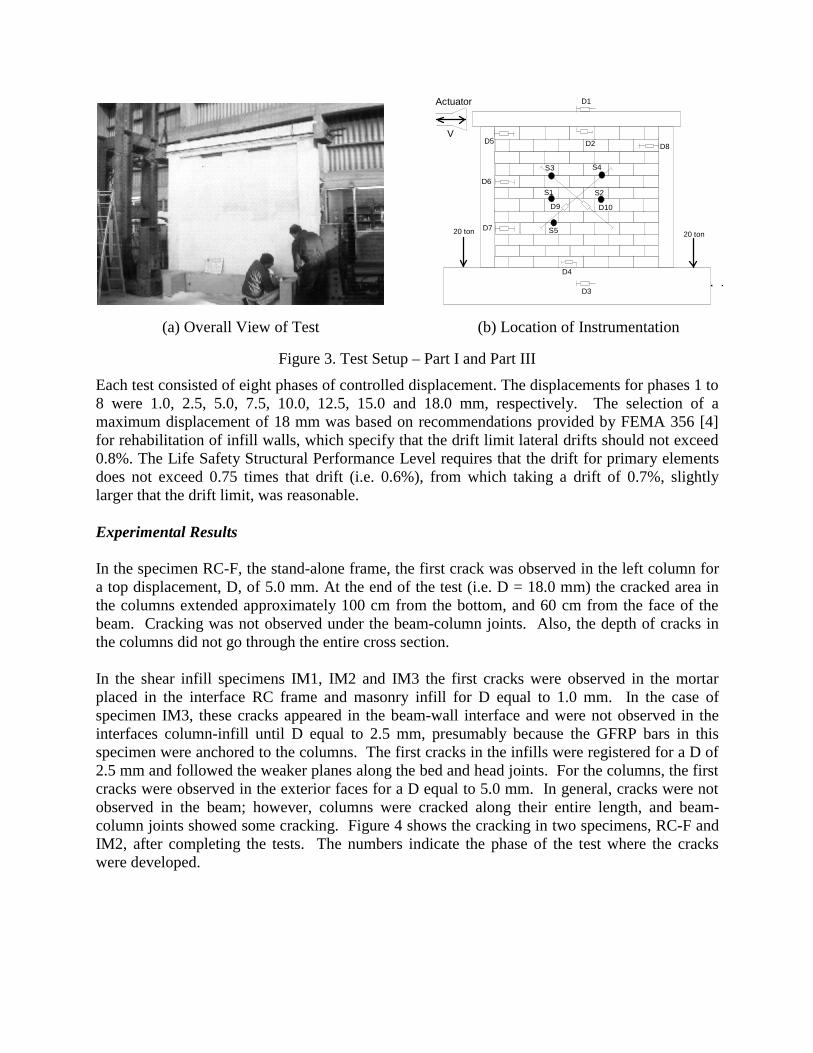
3. Part I: In-Plane Cyclic Loading The specimens were tested under in-plane cyclic lateral load by following a displacement-controlled method. A hydraulic actuator was used to generate the in-plane load, which was applied at the top of the specimen. Two vertical loads were applied by means of hydraulic jacks to the base beam to avoid rocking and sliding of the specimen. Figure 3a shows an overall view of the test setup. A total of ten linear variable differential transducers (LVDTs) were used to monitor the wall displacements. Five strain gauges were adhered to the GFRP bars in specimens IM2 and IM3. Figure 3b illustrates the location of the instrumentation (D = LVDT, S = Strain Gauge).
Actuator
V
S2 S1
S4 S3
S5
D1
D3
D2
D4
D5
D6
D7
D8
D9 D10
20 ton 20 ton
30 ton
(a) Overall View of Test (b) Location of Instrumentation
Figure 3. Test Setup – Part I and Part III
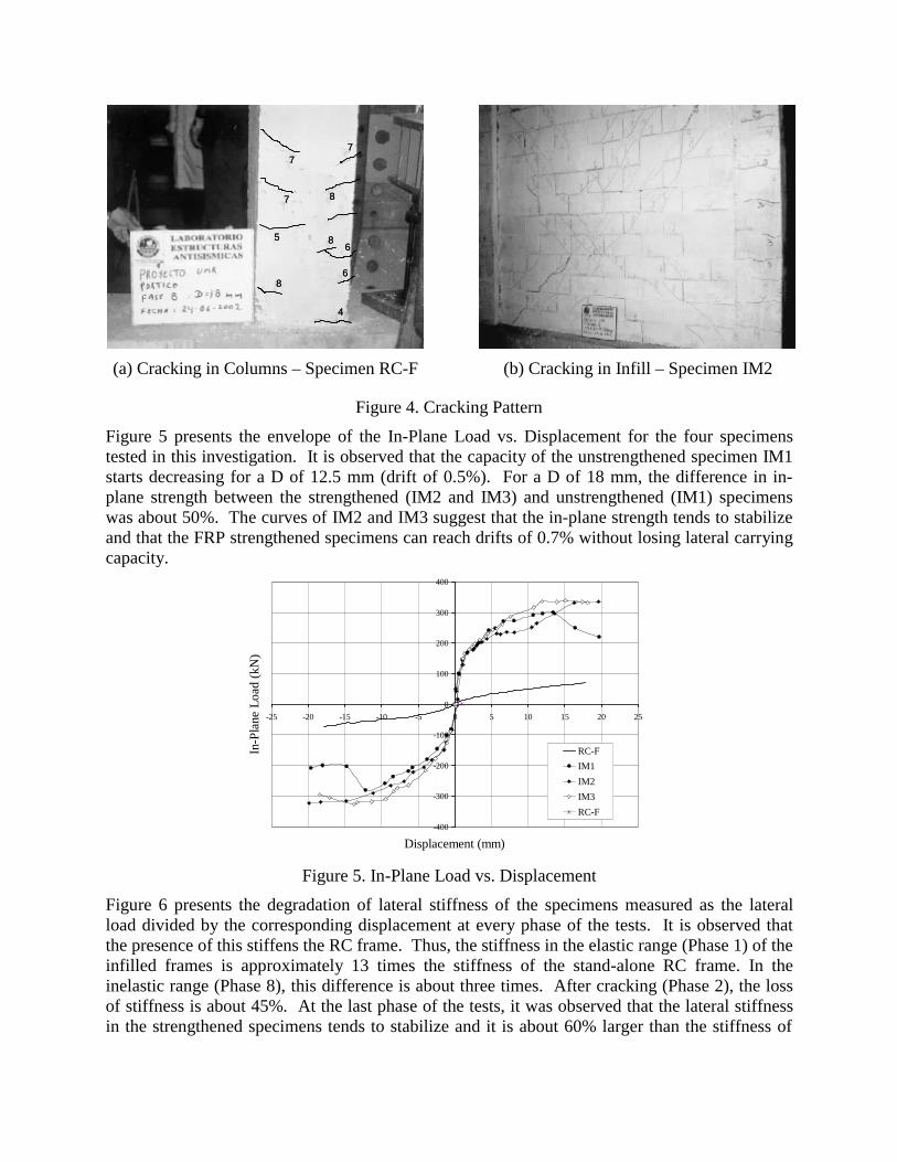
Each test consisted of eight phases of controlled displacement. The displacements for phases 1 to 8 were 1.0, 2.5, 5.0, 7.5, 10.0, 12.5, 15.0 and 18.0 mm, respectively. The selection of a maximum displacement of 18 mm was based on recommendations provided by FEMA 356 [4] for rehabilitation of infill walls, which specify that the drift limit lateral drifts should not exceed 0.8%. The Life Safety Structural Performance Level requires that the drift for primary elements does not exceed 0.75 times that drift (i.e. 0.6%), from which taking a drift of 0.7%, slightly larger that the drift limit, was reasonable. Experimental Results In the specimen RC-F, the stand-alone frame, the first crack was observed in the left column for a top displacement, D, of 5.0 mm. At the end of the test (i.e. D = 18.0 mm) the cracked area in the columns extended approximately 100 cm from the bottom, and 60 cm from the face of the beam. Cracking was not observed under the beam-column joints. Also, the depth of cracks in the columns did not go through the entire cross section. In the shear infill specimens IM1, IM2 and IM3 the first cracks were observed in the mortar placed in the interface RC frame and masonry infill for D equal to 1.0 mm. In the case of specimen IM3, these cracks appeared in the beam-wall interface and were not observed in the interfaces column-infill until D equal to 2.5 mm, presumably because the GFRP bars in this specimen were anchored to the columns. The first cracks in the infills were registered for a D of 2.5 mm and followed the weaker planes along the bed and head joints. For the columns, the first cracks were observed in the exterior faces for a D equal to 5.0 mm. In general, cracks were not observed in the beam; however, columns were cracked along their entire length, and beam-column joints showed some cracking. Figure 4 shows the cracking in two specimens, RC-F and IM2, after completing the tests. The numbers indicate the phase of the test where the cracks were developed.
77
7 8
856
86
4
77
7 8
856
86
4
(a) Cracking in Columns – Specimen RC-F (b) Cracking in Infill – Specimen IM2
Figure 4. Cracking Pattern
Figure 5 presents the envelope of the In-Plane Load vs. Displacement for the four specimens tested in this investigation. It is observed that the capacity of the unstrengthened specimen IM1 starts decreasing for a D of 12.5 mm (drift of 0.5%). For a D of 18 mm, the difference in in-plane strength between the strengthened (IM2 and IM3) and unstrengthened (IM1) specimens was about 50%. The curves of IM2 and IM3 suggest that the in-plane strength tends to stabilize and that the FRP strengthened specimens can reach drifts of 0.7% without losing lateral carrying capacity.
-400
-300
-200
-100
0
100
200
300
400
-25 -20 -15 -10 -5 0 5 10 15 20 25
Displacement (mm)
In-P
lane
Loa
d (k
N)
RC-FIM1IM2IM3RC-F
Figure 5. In-Plane Load vs. Displacement
Figure 6 presents the degradation of lateral stiffness of the specimens measured as the lateral load divided by the corresponding displacement at every phase of the tests. It is observed that the presence of this stiffens the RC frame. Thus, the stiffness in the elastic range (Phase 1) of the infilled frames is approximately 13 times the stiffness of the stand-alone RC frame. In the inelastic range (Phase 8), this difference is about three times. After cracking (Phase 2), the loss of stiffness is about 45%. At the last phase of the tests, it was observed that the lateral stiffness in the strengthened specimens tends to stabilize and it is about 60% larger than the stiffness of
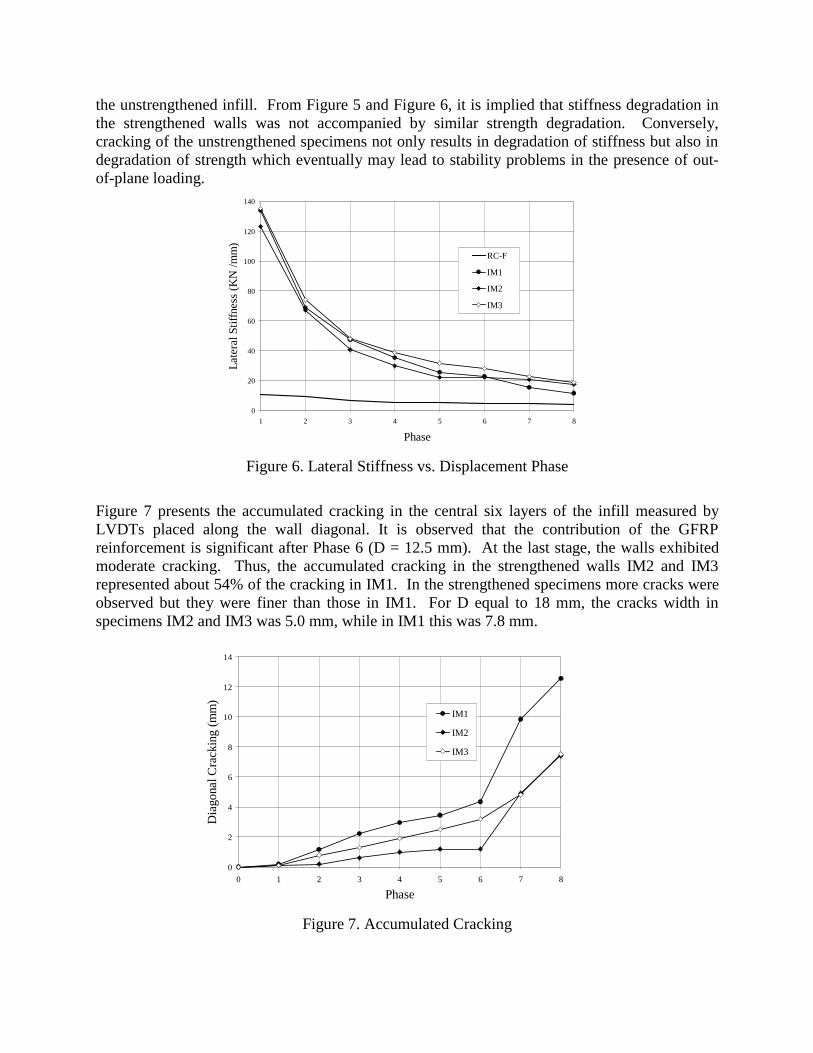
the unstrengthened infill. From Figure 5 and Figure 6, it is implied that stiffness degradation in the strengthened walls was not accompanied by similar strength degradation. Conversely, cracking of the unstrengthened specimens not only results in degradation of stiffness but also in degradation of strength which eventually may lead to stability problems in the presence of out-of-plane loading.
0
20
40
60
80
100
120
140
1 2 3 4 5 6 7 8
Phase
Late
ral S
tiffn
ess
(KN
/mm
)
RC-F
IM1
IM2
IM3
Figure 6. Lateral Stiffness vs. Displacement Phase
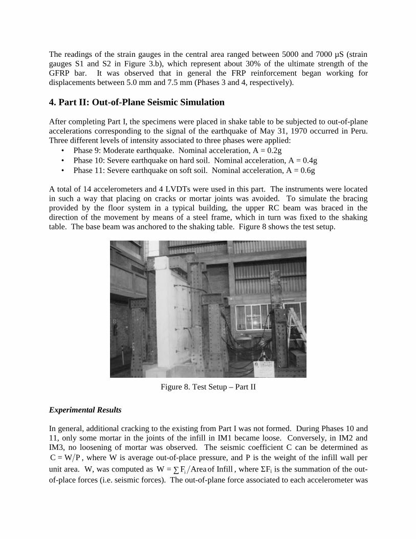
Figure 7 presents the accumulated cracking in the central six layers of the infill measured by LVDTs placed along the wall diagonal. It is observed that the contribution of the GFRP reinforcement is significant after Phase 6 (D = 12.5 mm). At the last stage, the walls exhibited moderate cracking. Thus, the accumulated cracking in the strengthened walls IM2 and IM3 represented about 54% of the cracking in IM1. In the strengthened specimens more cracks were observed but they were finer than those in IM1. For D equal to 18 mm, the cracks width in specimens IM2 and IM3 was 5.0 mm, while in IM1 this was 7.8 mm.
0
2
4
6
8
10
12
14
0 1 2 3 4 5 6 7 8
Phase
Dia
gona
l Cra
ckin
g (m
m)
IM1
IM2
IM3
Figure 7. Accumulated Cracking
The readings of the strain gauges in the central area ranged between 5000 and 7000 µS (strain gauges S1 and S2 in Figure 3.b), which represent about 30% of the ultimate strength of the GFRP bar. It was observed that in general the FRP reinforcement began working for displacements between 5.0 mm and 7.5 mm (Phases 3 and 4, respectively). 4. Part II: Out-of-Plane Seismic Simulation After completing Part I, the specimens were placed in shake table to be subjected to out-of-plane accelerations corresponding to the signal of the earthquake of May 31, 1970 occurred in Peru. Three different levels of intensity associated to three phases were applied:
• Phase 9: Moderate earthquake. Nominal acceleration, A = 0.2g • Phase 10: Severe earthquake on hard soil. Nominal acceleration, A = 0.4g • Phase 11: Severe earthquake on soft soil. Nominal acceleration, A = 0.6g
A total of 14 accelerometers and 4 LVDTs were used in this part. The instruments were located in such a way that placing on cracks or mortar joints was avoided. To simulate the bracing provided by the floor system in a typical building, the upper RC beam was braced in the direction of the movement by means of a steel frame, which in turn was fixed to the shaking table. The base beam was anchored to the shaking table. Figure 8 shows the test setup.
Figure 8. Test Setup – Part II
Experimental Results In general, additional cracking to the existing from Part I was not formed. During Phases 10 and 11, only some mortar in the joints of the infill in IM1 became loose. Conversely, in IM2 and IM3, no loosening of mortar was observed. The seismic coefficient C can be determined as
PWC = , where W is average out-of-place pressure, and P is the weight of the infill wall per unit area. W, was computed as InfillofAreaFW i∑= , where ΣFi is the summation of the out-of-place forces (i.e. seismic forces). The out-of-plane force associated to each accelerometer was
estimated as tiii APaF = , where ai is the accelerometer recording and Ati is the tributary area of each accelerometer. The C values and average out-of-plane pressures for each specimen are presented in Table 2. It is observed that both C and W values increase in the strengthened walls. In each specimen the W values largerly surpass the maximum values specified by FEMA 356 for infill walls subjected to out-of-plane loading when arching action develops. The results indicate that each infill complies with the FEMA 356 requirements and that flexural strengthening would not be required to walls that have had drifts of up to 0.7% due to their high transversal stiffness.
Table 2. Results of Part II
Specimen Seismic Coefficient, C Average Out-of-Plane Pressure, W IM1 0.69 11.2 kPa IM2 0.76 13.8 kPa IM3 0.72 13.0 kPa
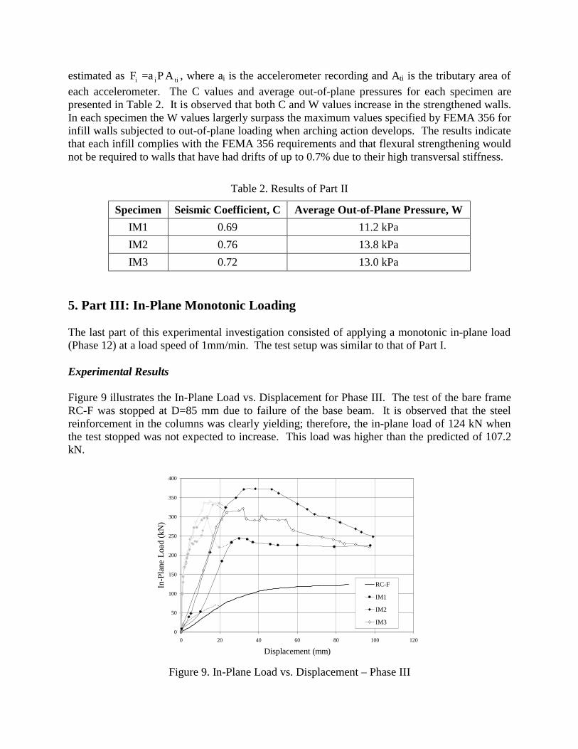
5. Part III: In-Plane Monotonic Loading The last part of this experimental investigation consisted of applying a monotonic in-plane load (Phase 12) at a load speed of 1mm/min. The test setup was similar to that of Part I. Experimental Results Figure 9 illustrates the In-Plane Load vs. Displacement for Phase III. The test of the bare frame RC-F was stopped at D=85 mm due to failure of the base beam. It is observed that the steel reinforcement in the columns was clearly yielding; therefore, the in-plane load of 124 kN when the test stopped was not expected to increase. This load was higher than the predicted of 107.2 kN.
0
50
100
150
200
250
300
350
400
0 20 40 60 80 100 120
Displacement (mm)
In-P
lane
Loa
d (k
N)
RC-F
IM1
IM2
IM3
Figure 9. In-Plane Load vs. Displacement – Phase III
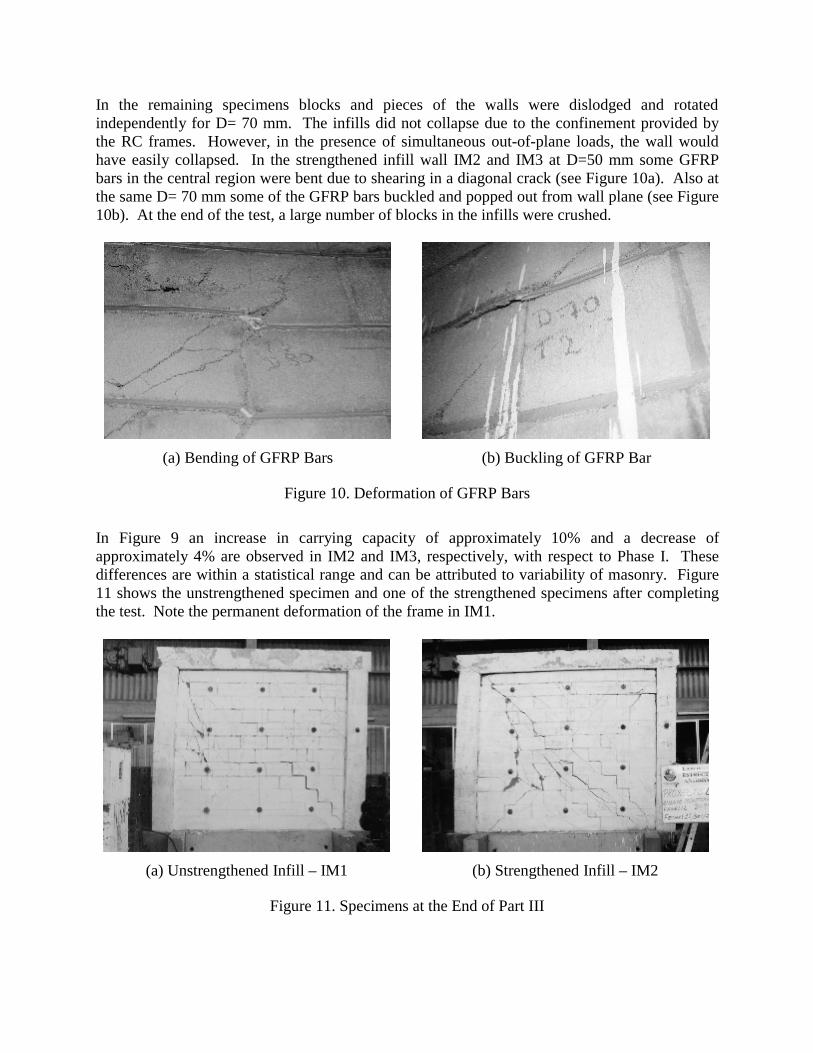
In the remaining specimens blocks and pieces of the walls were dislodged and rotated independently for D= 70 mm. The infills did not collapse due to the confinement provided by the RC frames. However, in the presence of simultaneous out-of-plane loads, the wall would have easily collapsed. In the strengthened infill wall IM2 and IM3 at D=50 mm some GFRP bars in the central region were bent due to shearing in a diagonal crack (see Figure 10a). Also at the same D= 70 mm some of the GFRP bars buckled and popped out from wall plane (see Figure 10b). At the end of the test, a large number of blocks in the infills were crushed.
(a) Bending of GFRP Bars (b) Buckling of GFRP Bar
Figure 10. Deformation of GFRP Bars
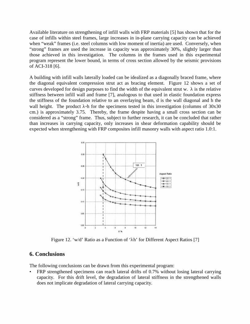
In Figure 9 an increase in carrying capacity of approximately 10% and a decrease of approximately 4% are observed in IM2 and IM3, respectively, with respect to Phase I. These differences are within a statistical range and can be attributed to variability of masonry. Figure 11 shows the unstrengthened specimen and one of the strengthened specimens after completing the test. Note the permanent deformation of the frame in IM1.
(a) Unstrengthened Infill – IM1 (b) Strengthened Infill – IM2
Figure 11. Specimens at the End of Part III
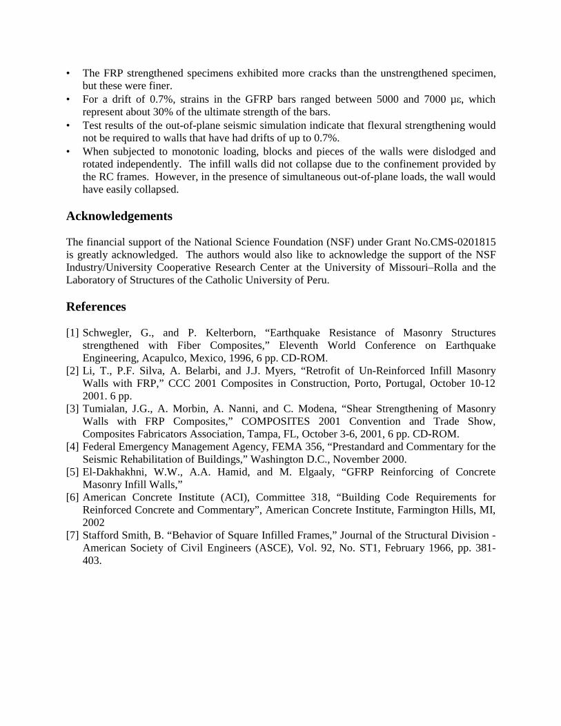
Available literature on strengthening of infill walls with FRP materials [5] has shown that for the case of infills within steel frames, large increases in in-plane carrying capacity can be achieved when “weak” frames (i.e. steel columns with low moment of inertia) are used. Conversely, when “strong” frames are used the increase in capacity was approximately 30%, slightly larger than those achieved in this investigation. The columns in the frames used in this experimental program represent the lower bound, in terms of cross section allowed by the seismic provisions of ACI-318 [6]. A building with infill walls laterally loaded can be idealized as a diagonally braced frame, where the diagonal equivalent compression strut act as bracing element. Figure 12 shows a set of curves developed for design purposes to find the width of the equivalent strut w. λ is the relative stiffness between infill wall and frame [7], analogous to that used in elastic foundation express the stiffness of the foundation relative to an overlaying beam, d is the wall diagonal and h the wall height. The product λ∗h for the specimens tested in this investigation (columns of 30x30 cm.) is approximately 3.75. Thereby, the frame despite having a small cross section can be considered as a “strong” frame. Thus, subject to further research, it can be concluded that rather than increases in carrying capacity, only increases in shear deformation capability should be expected when strengthening with FRP composites infill masonry walls with aspect ratio 1.0:1.
Figure 12. ‘w/d’ Ratio as a Function of ‘λh’ for Different Aspect Ratios [7]
6. Conclusions The following conclusions can be drawn from this experimental program: • FRP strengthened specimens can reach lateral drifts of 0.7% without losing lateral carrying
capacity. For this drift level, the degradation of lateral stiffness in the strengthened walls does not implicate degradation of lateral carrying capacity.
• The FRP strengthened specimens exhibited more cracks than the unstrengthened specimen, but these were finer.
• For a drift of 0.7%, strains in the GFRP bars ranged between 5000 and 7000 µε, which represent about 30% of the ultimate strength of the bars.
• Test results of the out-of-plane seismic simulation indicate that flexural strengthening would not be required to walls that have had drifts of up to 0.7%.
• When subjected to monotonic loading, blocks and pieces of the walls were dislodged and rotated independently. The infill walls did not collapse due to the confinement provided by the RC frames. However, in the presence of simultaneous out-of-plane loads, the wall would have easily collapsed.
Acknowledgements The financial support of the National Science Foundation (NSF) under Grant No.CMS-0201815 is greatly acknowledged. The authors would also like to acknowledge the support of the NSF Industry/University Cooperative Research Center at the University of Missouri–Rolla and the Laboratory of Structures of the Catholic University of Peru. References [1] Schwegler, G., and P. Kelterborn, “Earthquake Resistance of Masonry Structures
strengthened with Fiber Composites,” Eleventh World Conference on Earthquake Engineering, Acapulco, Mexico, 1996, 6 pp. CD-ROM.
[2] Li, T., P.F. Silva, A. Belarbi, and J.J. Myers, “Retrofit of Un-Reinforced Infill Masonry Walls with FRP,” CCC 2001 Composites in Construction, Porto, Portugal, October 10-12 2001. 6 pp.
[3] Tumialan, J.G., A. Morbin, A. Nanni, and C. Modena, “Shear Strengthening of Masonry Walls with FRP Composites,” COMPOSITES 2001 Convention and Trade Show, Composites Fabricators Association, Tampa, FL, October 3-6, 2001, 6 pp. CD-ROM.
[4] Federal Emergency Management Agency, FEMA 356, “Prestandard and Commentary for the Seismic Rehabilitation of Buildings,” Washington D.C., November 2000.
[5] El-Dakhakhni, W.W., A.A. Hamid, and M. Elgaaly, “GFRP Reinforcing of Concrete Masonry Infill Walls,”
[6] American Concrete Institute (ACI), Committee 318, “Building Code Requirements for Reinforced Concrete and Commentary”, American Concrete Institute, Farmington Hills, MI, 2002
[7] Stafford Smith, B. “Behavior of Square Infilled Frames,” Journal of the Structural Division - American Society of Civil Engineers (ASCE), Vol. 92, No. ST1, February 1966, pp. 381-403.