bedienungsanleitung wsg 50
TRANSCRIPT

Mounting and Operating Manual
Electrical Parallel Gripper WSG 50 Firmware Version: 4.0
Hardware Version: 6
March 2017


-1-
Contents
1 Introduction ...................................................................................................... 3
2 About this manual ............................................................................................. 4
2.1 Applicable documents .................................................................................................. 4
2.2 Target audience ............................................................................................................ 4
2.3 Notation and symbols ................................................................................................... 4
3 Basic safety notes .............................................................................................. 5
3.1 Intended use ................................................................................................................ 5
3.2 Environmental and operating conditions ....................................................................... 5
3.3 Product safety .............................................................................................................. 5
3.3.1 Protective equipment ............................................................................................................ 5
3.3.2 Constructional changes, attachments, or modifications ....................................................... 6
3.3.3 Special standards ................................................................................................................... 6
3.4 Personnel qualification ................................................................................................. 6
3.5 Safety Considerations ................................................................................................... 6
3.6 Notes on particular risks ............................................................................................... 6
4 Warranty ........................................................................................................... 7
5 Scope of delivery ............................................................................................... 7
6 Accessories ........................................................................................................ 7
7 Technical Data ................................................................................................... 8
7.1 Outer dimensions ......................................................................................................... 8
7.2 Nominal mechanical data ............................................................................................. 9
7.2.1 Mechanical finger load .......................................................................................................... 9
7.2.2 Gripping force ...................................................................................................................... 10
7.3 Nominal electrical data ............................................................................................... 12
7.4 Interfaces and connections ......................................................................................... 13
7.4.1 Assignments for the internal terminal strip ........................................................................ 13
7.4.2 Connections of own lines .................................................................................................... 14
7.4.3 Termination resistors .......................................................................................................... 14
7.4.4 Fuse...................................................................................................................................... 15
7.4.5 PROFIBUS ............................................................................................................................. 15
7.4.6 CAN-Bus ............................................................................................................................... 15
7.4.7 Power supply and RS-232 (serial interface) ......................................................................... 16
7.4.8 Ethernet ............................................................................................................................... 17
7.4.9 Digital inputs/outputs.......................................................................................................... 18
7.4.10 Base jaw with sensor port ................................................................................................... 19

-2-
7.5 Name plate ................................................................................................................ 21
8 Installation ...................................................................................................... 22
8.1 Installation instructions .............................................................................................. 22
8.2 Mechanical connection ............................................................................................... 22
8.3 Electrical Connection .................................................................................................. 23
8.4 Installation of the fingers ............................................................................................ 25
8.5 Initial startup.............................................................................................................. 25
8.6 Changing the IP address and using DHCP ..................................................................... 28
9 Operation ........................................................................................................ 28
9.1 Operating software .................................................................................................... 29
9.2 Memory card .............................................................................................................. 29
9.3 Boot process .............................................................................................................. 29
9.4 Display of operating state ........................................................................................... 30
9.5 Status word and gripper state ..................................................................................... 32
9.5.1 Status word .......................................................................................................................... 32
9.5.2 Gripper state ........................................................................................................................ 33
9.6 Homing the module .................................................................................................... 34
9.7 Gripping, part detection and grip monitoring .............................................................. 35
9.8 Software limit switch .................................................................................................. 36
9.9 Fast Stops requiring acknowledgment ......................................................................... 37
9.10 Log memory ............................................................................................................... 38
9.11 Thermal monitor ........................................................................................................ 38
9.12 Monitoring the drive current ...................................................................................... 39
9.13 Monitoring the supply voltage .................................................................................... 40
9.14 Overdrive Mode ......................................................................................................... 40
9.15 Access restrictions for the web user interface .............................................................. 42
9.16 Command interface .................................................................................................... 43
9.17 Scripting ..................................................................................................................... 44
9.18 Resetting the configuration ......................................................................................... 44
9.19 Implementing the gripping process ............................................................................. 44
10 Maintenance and cleaning ............................................................................... 46
11 Troubleshooting .............................................................................................. 47
11.1 The gripper jaws don’t move....................................................................................... 47
11.2 Module stops abruptly ................................................................................................ 47
11.3 No connection to the web interface ............................................................................ 48
12 EC Declaration of Incorporation ....................................................................... 49
-3-
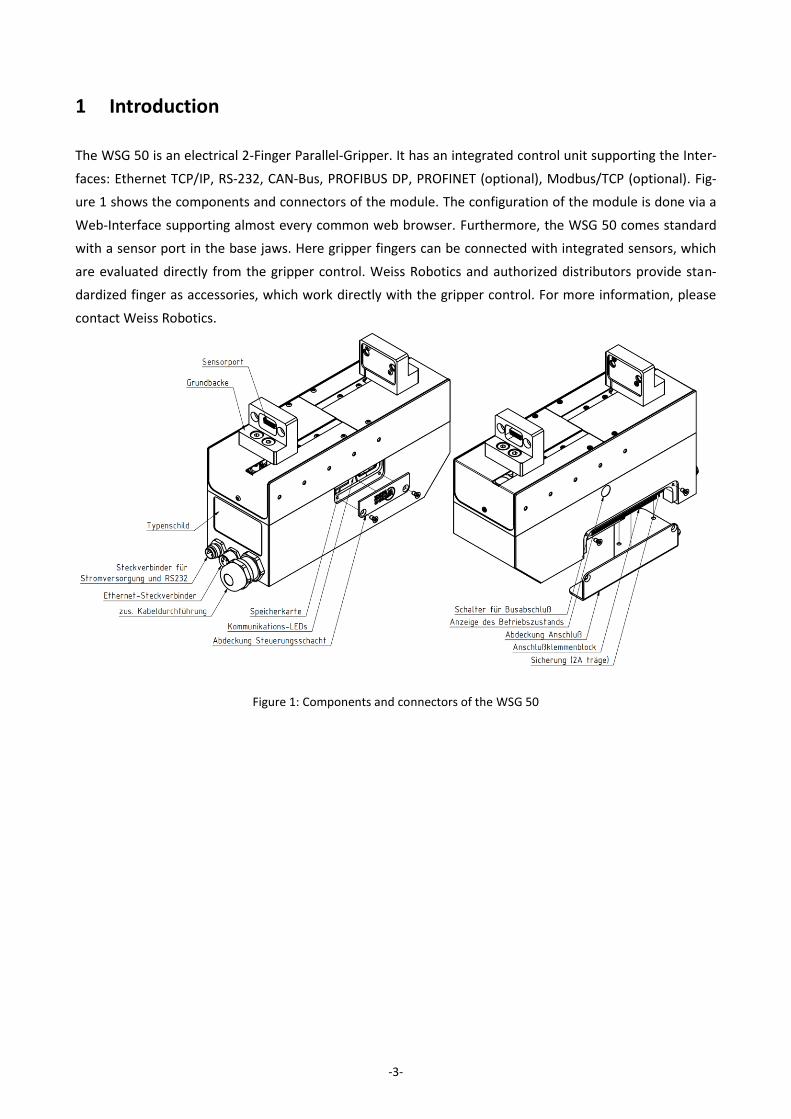
1 Introduction
The WSG 50 is an electrical 2-Finger Parallel-Gripper. It has an integrated control unit supporting the Inter-
faces: Ethernet TCP/IP, RS-232, CAN-Bus, PROFIBUS DP, PROFINET (optional), Modbus/TCP (optional). Fig-
ure 1 shows the components and connectors of the module. The configuration of the module is done via a
Web-Interface supporting almost every common web browser. Furthermore, the WSG 50 comes standard
with a sensor port in the base jaws. Here gripper fingers can be connected with integrated sensors, which
are evaluated directly from the gripper control. Weiss Robotics and authorized distributors provide stan-
dardized finger as accessories, which work directly with the gripper control. For more information, please
contact Weiss Robotics.
Figure 1: Components and connectors of the WSG 50
-4-
2 About this manual
This instruction is an integral part of the product and contains important information for a safe and proper
assembly, commissioning, operation, maintenance and helps for an easier trouble shooting.
Before using the product, read and note the instruction, especially chapter 3 "Basic safety notes". This
manual is exclusively valid for the gripper type WSG 50.
2.1 Applicable documents
For more detailed information about the operation of this module, please see the following documents
which are available in PDF format on both the accompanying CD as well as via the WSG web interface:
WSG Command Set Reference Manual - Description of the binary command protocol (RS-232,
TCP/IP, CAN-Bus)
WSG GCL Reference Manual – Description of the text based command protocol (TCP/IP)
WSG Fieldbus Interface Manual - Description of the fieldbus interface (PROFIBUS, PROFINET, Mod-
bus/TCP)
WSG Scripting Reference Manual - Description of the optional script interpreter for the gripper
control system
Please find additional information about the warranty in our general terms and conditions, available online
at www.weiss-robotics.com.
2.2 Target audience
Target audience for these instructions are plant manufacturers and operators who keep this and other
documents supplied to the personnel at all times and also ask to read and observe particularly the safety
instructions and warnings.
In addition, it is aimed at professionals and technicians who read this manual, while they should particularly
observe the safety and warning notes at all times.
2.3 Notation and symbols
For better clarity, the following symbols are used in this manual:
Functional or safety-related information. Failure to comply may jeopardize the safety of per-
sonnel and equipment, damage the device or impair the function of the device.
Additional information for a better understanding of the facts described.

-5-
Reference to further information.
3 Basic safety notes
3.1 Intended use
The module was designed to grip and to temporarily and securely hold work pieces and objects.
Das The module is intended for installation in a machine/system. The requirements of the applica-
ble guidelines must be observed and complied with.
The module may be used only in the context of its defined application parameters.
To use this unit as intended, it is also essential to observe the technical data and installation and
operation notes in this manual and to comply with the maintenance intervals.
3.2 Environmental and operating conditions
The module may only be used within its defined application parameters.
It must be ensured that the module and the top jaws are sufficiently dimensioned according to the
use case.
It must be ensured that the environment is clean and the ambient temperature corresponds to the
specifications catalogue. Please observe the maintenance instructions (see chapter 10).
It must be ensured that the environment is free from splash and vapours as well as from abrasion
or process dust. Excepted are modules that are specifically designed for dirty environments.
3.3 Product safety
Dangers arise from the module, if e.g.:
The module is not used in accordance with its intended purpose.
The module is not installed or maintained properly.
The safety and installation notes are not observed.
Avoid any manner of working that may interfere with the function and operational safety of the module.
Wear protective equipment.
3.3.1 Protective equipment
Provide protective equipment per EC Machine Directive

-6-
3.3.2 Constructional changes, attachments, or modifications
Additional drill holes, threads, or attachments that are not offered as accessories by Weiss Robotics may be
attached only with permission of Weiss Robotics.
3.3.3 Special standards
The following standards are met:
Fast transients on supply and I/O lines (burst) to IEC / EN 61000-4-4
FH power supply to IEC/EN 61000-4-6
HF radiation according to IEC/EN 61000-4-3
Emissions according to EN 55011:2009 Class A (corresponds to EN 61000-6-4:2007)
Power frequency magnetic field according to EN 61000-4-8
3.4 Personnel qualification
The assembly, initial commissioning, maintenance, and repair of the module may be performed only by
trained specialist personnel. Every person called upon by the operator to work on the module must have
read and understood the complete assembly and operating manual especially chapter 3 "Basic safety
notes”. This applies particularly to personnel only used occasionally, such as maintenance personnel.
3.5 Safety Considerations
Avoid any operation that affects the function and reliability of the module.
Observe applicable on site safety and accident prevention regulations.
3.6 Notes on particular risks
Generally valid:
Risk of injury from objects falling and being ejected
The danger zone must be surrounded by a safety fence during operation.
Risk of injury due to squeezing and bumping during movement of the gripper jaws and breaking or loosen-
ing of the gripper fingers
While disassembling uncontrollable moves of parts of the gripper possible!
Do not move parts by hand when the energy supply is connected.
Do not reach into the open mechanism or the movement area of the module.
Remove the energy supplies before installation, modification, maintenance, or adjustment work.

-7-
Make sure, that no residual energy remains in the system.
Perform maintenance, modifications, and additions outside the danger zone.
For all work, secure the unit against accidental operation.
Take a precautionary approach by maintenance and disassembly.
Only special trained staff should disassemble the module.
4 Warranty
The warranty is valid for 24 months from the delivery date to the production facility under the following
conditions:
Intended use in 1-shift operation
Observe the mandatory maintenance and lubrication intervals.
Observe the environmental and operating conditions.
Parts touching the work piece and wearing parts are not part of the warranty.
The module is considered defective if its basic function “gripping” is no longer given.
5 Scope of delivery
The scope of delivery includes:
• WSG 50 servo-electric 2-finger parallel gripper
• M12x1,5 EMC screw connection
• Operating manual
• CD with documentation and firmware
6 Accessories
The following accessories that are required for the module must be ordered separately:
• Ethernet data cable, length 5 m, 4-pole M8 to RJ-45, for WSG gripper modules and KMS 40,
Part No. AL-ETH-4P-5M (straight) and AL-ETH-4PW-5M (right angle)
• Power supply cable, length 5 m, 6-pole M8 connector to free wire ends, shielded,
Part No. AL-M8-6P-5M (straight) and AL-M8-6PW-5M( right angle)
• PROFINET RT (software license), OPT-WSG-PN
• Universal Finger WSG-F
• Force Measurement Finger WSG-FMF
• Tactile Sensor Finger WSG-DSA
-8-
Please order accessories separately. More accessories can be found on our web site www.weiss-
robotics.com.
7 Technical Data
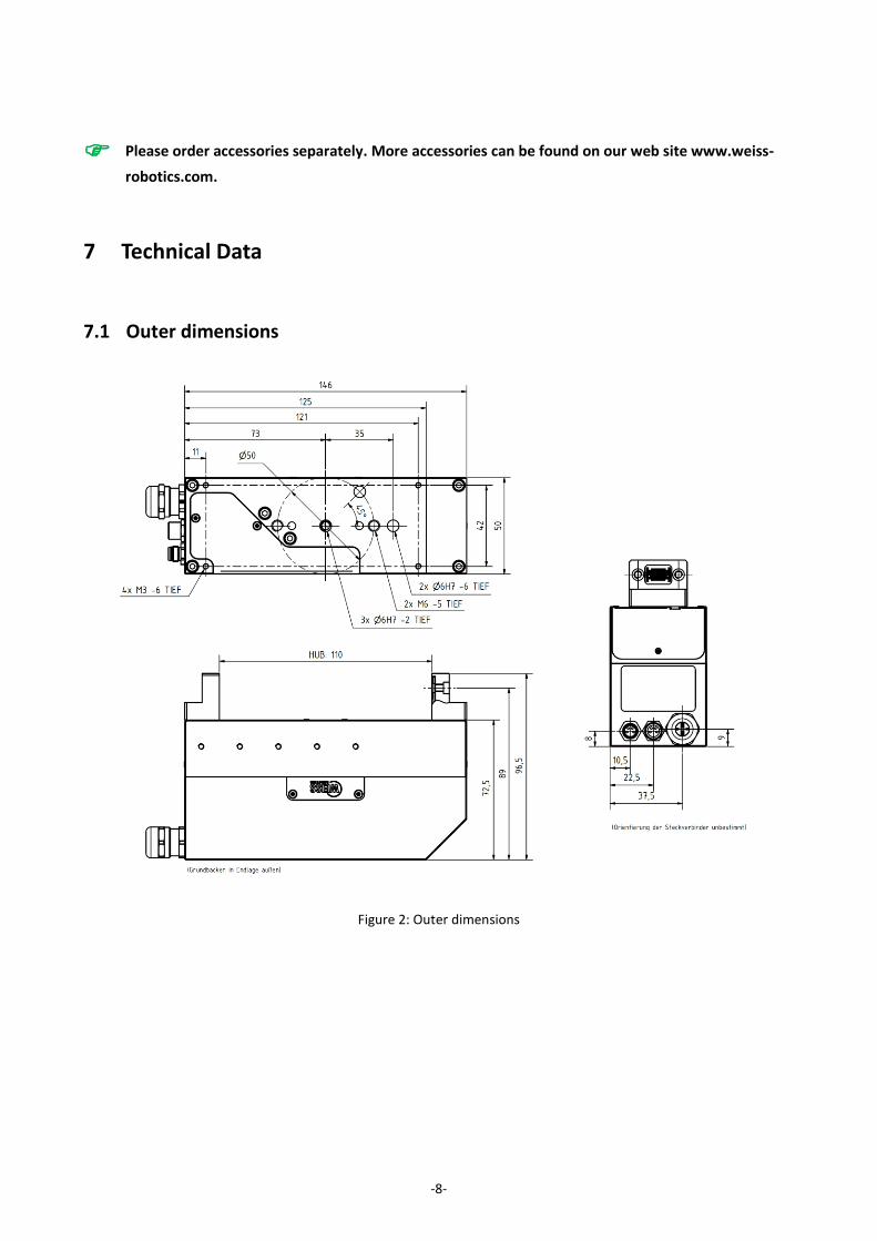
7.1 Outer dimensions
Figure 2: Outer dimensions
-9-
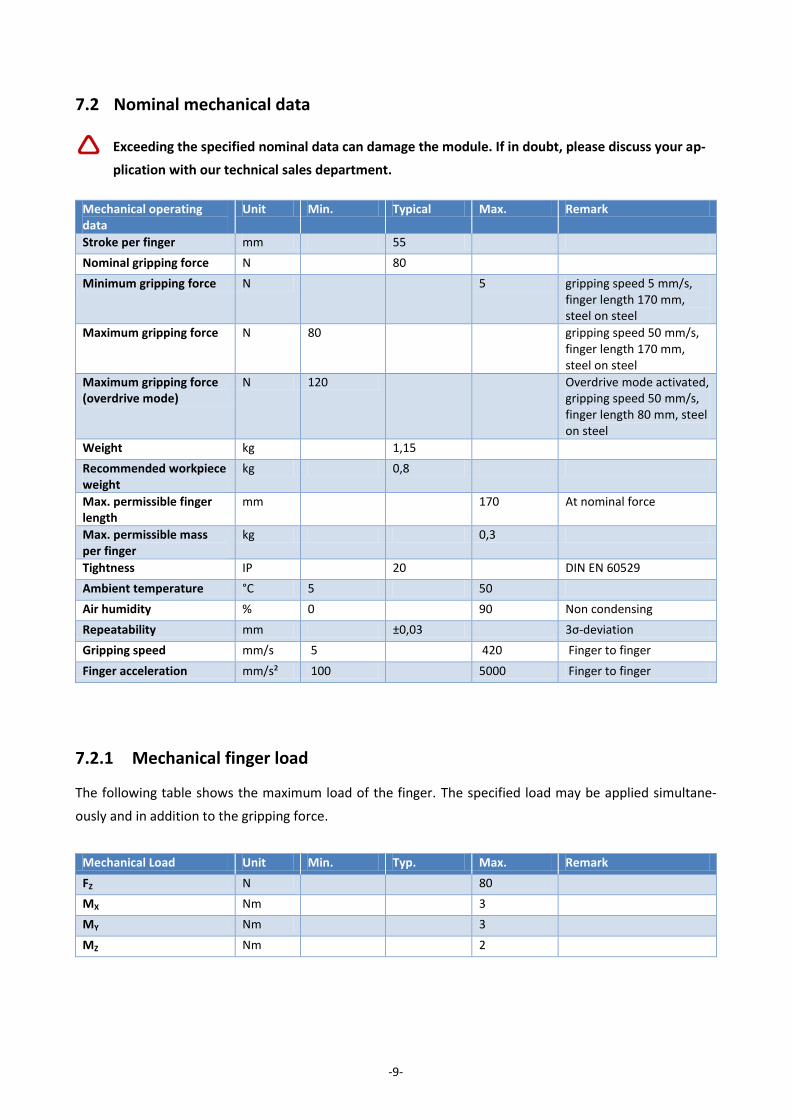
7.2 Nominal mechanical data
Exceeding the specified nominal data can damage the module. If in doubt, please discuss your ap-
plication with our technical sales department.
Mechanical operating data
Unit Min. Typical Max. Remark
Stroke per finger mm 55
Nominal gripping force N 80
Minimum gripping force N 5 gripping speed 5 mm/s, finger length 170 mm, steel on steel
Maximum gripping force N 80 gripping speed 50 mm/s, finger length 170 mm, steel on steel
Maximum gripping force (overdrive mode)
N 120 Overdrive mode activated, gripping speed 50 mm/s, finger length 80 mm, steel on steel
Weight kg 1,15
Recommended workpiece weight
kg 0,8
Max. permissible finger length
mm 170 At nominal force
Max. permissible mass per finger
kg 0,3
Tightness IP 20 DIN EN 60529
Ambient temperature °C 5 50
Air humidity % 0 90 Non condensing
Repeatability mm ±0,03 3σ-deviation
Gripping speed mm/s 5 420 Finger to finger
Finger acceleration mm/s² 100 5000 Finger to finger
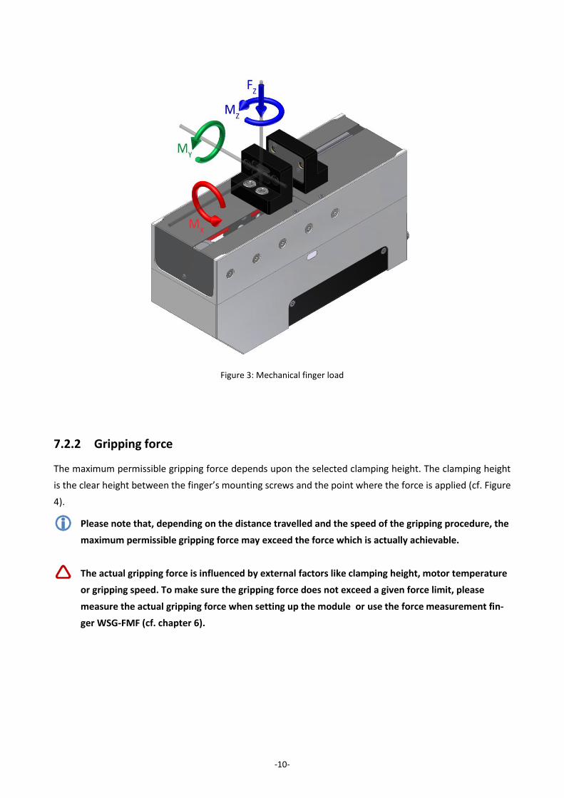
7.2.1 Mechanical finger load
The following table shows the maximum load of the finger. The specified load may be applied simultane-
ously and in addition to the gripping force.
Mechanical Load Unit Min. Typ. Max. Remark
FZ N 80
MX Nm 3
MY Nm 3
MZ Nm 2
-10-
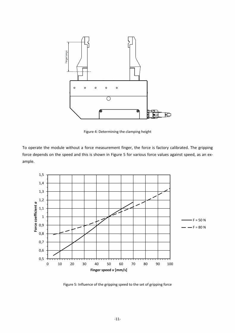
7.2.2 Gripping force
The maximum permissible gripping force depends upon the selected clamping height. The clamping height
is the clear height between the finger’s mounting screws and the point where the force is applied (cf. Figure
4).
Please note that, depending on the distance travelled and the speed of the gripping procedure, the
maximum permissible gripping force may exceed the force which is actually achievable.
The actual gripping force is influenced by external factors like clamping height, motor temperature
or gripping speed. To make sure the gripping force does not exceed a given force limit, please
measure the actual gripping force when setting up the module or use the force measurement fin-
ger WSG-FMF (cf. chapter 6).
Figure 3: Mechanical finger load
-11-
To operate the module without a force measurement finger, the force is factory calibrated. The gripping
force depends on the speed and this is shown in Figure 5 for various force values against speed, as an ex-
ample.
Figure 5: Influence of the gripping speed to the set of gripping force
Figure 4: Determining the clamping height
0,5
0,6
0,7
0,8
0,9
1
1,1
1,2
1,3
1,4
1,5
0 10 20 30 40 50 60 70 80 90 100
Forc
e c
oe
ffic
ien
t a
Finger speed v [mm/s]
F = 50 N
F = 80 N
-12-
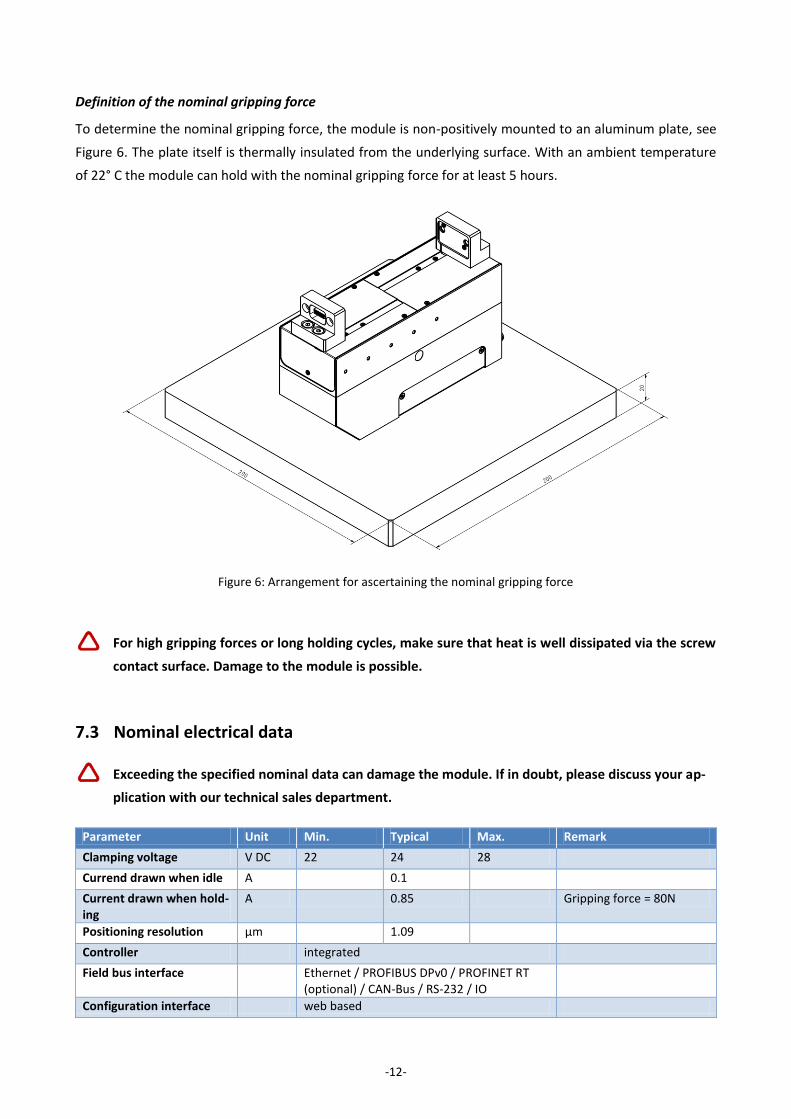
Definition of the nominal gripping force
To determine the nominal gripping force, the module is non-positively mounted to an aluminum plate, see
Figure 6. The plate itself is thermally insulated from the underlying surface. With an ambient temperature
of 22° C the module can hold with the nominal gripping force for at least 5 hours.
For high gripping forces or long holding cycles, make sure that heat is well dissipated via the screw
contact surface. Damage to the module is possible.
7.3 Nominal electrical data
Exceeding the specified nominal data can damage the module. If in doubt, please discuss your ap-
plication with our technical sales department.
Parameter Unit Min. Typical Max. Remark
Clamping voltage V DC 22 24 28
Currend drawn when idle A 0.1
Current drawn when hold-ing
A 0.85 Gripping force = 80N
Positioning resolution µm 1.09
Controller integrated
Field bus interface Ethernet / PROFIBUS DPv0 / PROFINET RT (optional) / CAN-Bus / RS-232 / IO
Configuration interface web based
Figure 6: Arrangement for ascertaining the nominal gripping force
-13-
7.4 Interfaces and connections
The module has various interfaces for control. The communications interface is selected and configured via
the web-based user interface (see chapter 9.16).
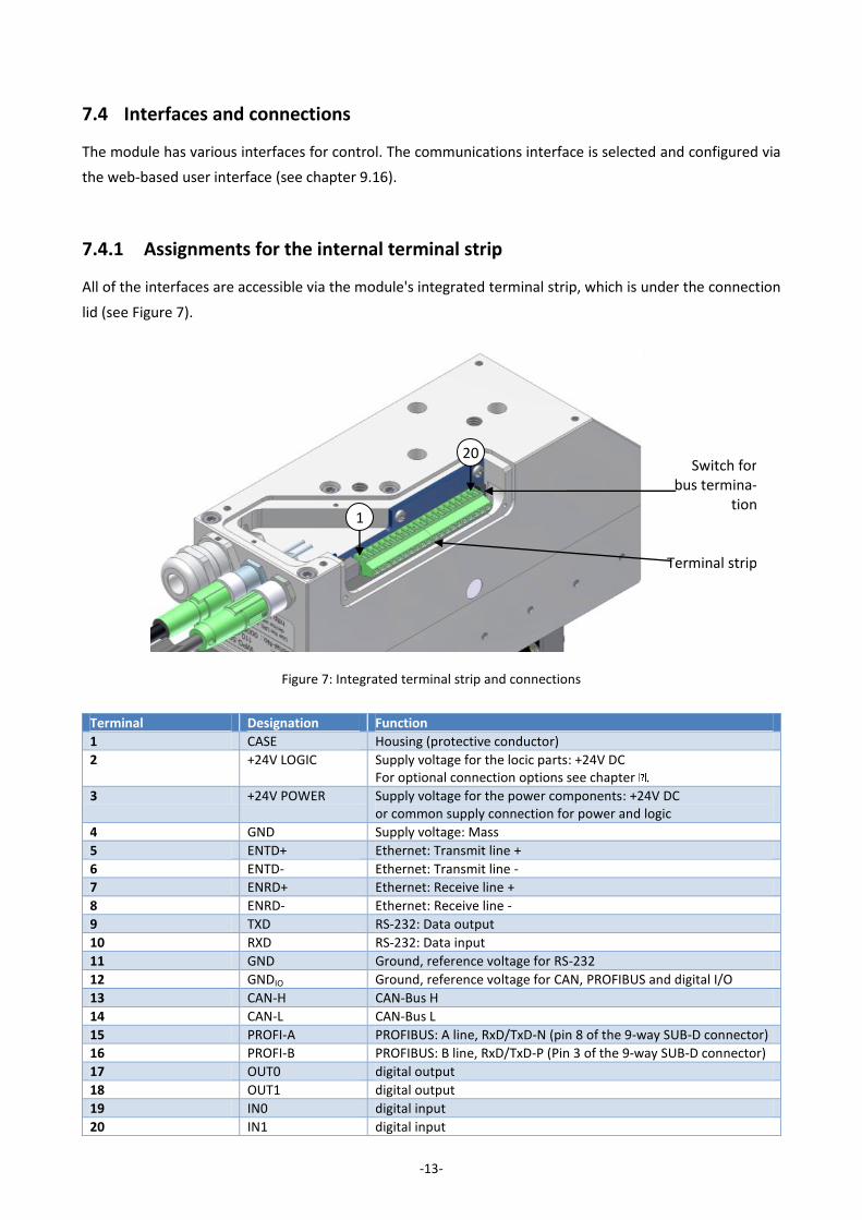
7.4.1 Assignments for the internal terminal strip
All of the interfaces are accessible via the module's integrated terminal strip, which is under the connection
lid (see Figure 7).
Terminal Designation Function
1 CASE Housing (protective conductor)
2 +24V LOGIC Supply voltage for the locic parts: +24V DC For optional connection options see chapter .
3 +24V POWER Supply voltage for the power components: +24V DC or common supply connection for power and logic
4 GND Supply voltage: Mass
5 ENTD+ Ethernet: Transmit line +
6 ENTD- Ethernet: Transmit line -
7 ENRD+ Ethernet: Receive line +
8 ENRD- Ethernet: Receive line -
9 TXD RS-232: Data output
10 RXD RS-232: Data input
11 GND Ground, reference voltage for RS-232
12 GNDIO Ground, reference voltage for CAN, PROFIBUS and digital I/O
13 CAN-H CAN-Bus H
14 CAN-L CAN-Bus L
15 PROFI-A PROFIBUS: A line, RxD/TxD-N (pin 8 of the 9-way SUB-D connector)
16 PROFI-B PROFIBUS: B line, RxD/TxD-P (Pin 3 of the 9-way SUB-D connector)
17 OUT0 digital output
18 OUT1 digital output
19 IN0 digital input
20 IN1 digital input
Figure 7: Integrated terminal strip and connections
Switch for bus termina-
tion
Terminal strip
1
20
-14-
With the exception of the RS-232 interface the interfaces are electrically isolated from the control system.
The interfaces use the same reference voltage GNDIO, which is accessible via the integrated terminal strip.
Should isolation of the interface lines not be wanted, the GND and GNDIO pins can be bridged.
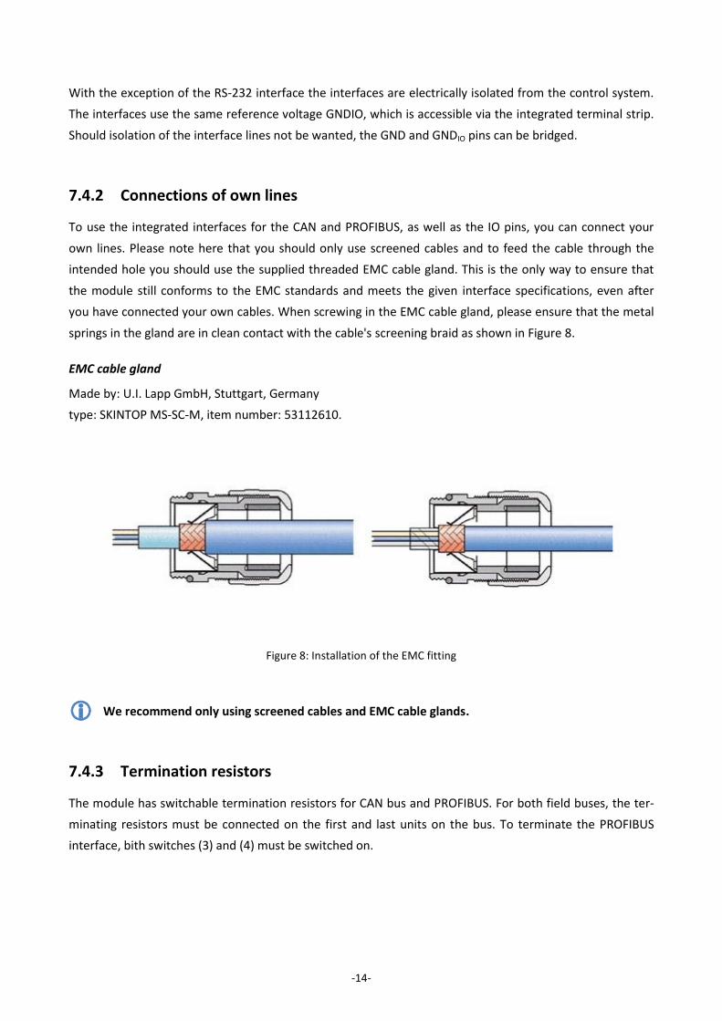
7.4.2 Connections of own lines
To use the integrated interfaces for the CAN and PROFIBUS, as well as the IO pins, you can connect your
own lines. Please note here that you should only use screened cables and to feed the cable through the
intended hole you should use the supplied threaded EMC cable gland. This is the only way to ensure that
the module still conforms to the EMC standards and meets the given interface specifications, even after
you have connected your own cables. When screwing in the EMC cable gland, please ensure that the metal
springs in the gland are in clean contact with the cable's screening braid as shown in Figure 8.
EMC cable gland
Made by: U.I. Lapp GmbH, Stuttgart, Germany
type: SKINTOP MS-SC-M, item number: 53112610.
We recommend only using screened cables and EMC cable glands.
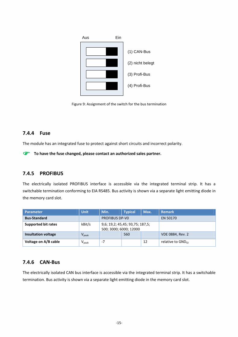
7.4.3 Termination resistors
The module has switchable termination resistors for CAN bus and PROFIBUS. For both field buses, the ter-
minating resistors must be connected on the first and last units on the bus. To terminate the PROFIBUS
interface, bith switches (3) and (4) must be switched on.
Figure 8: Installation of the EMC fitting
-15-
7.4.4 Fuse
The module has an integrated fuse to protect against short circuits and incorrect polarity.
To have the fuse changed, please contact an authorized sales partner.
7.4.5 PROFIBUS
The electrically isolated PROFIBUS interface is accessible via the integrated terminal strip. It has a
switchable termination conforming to EIA RS485. Bus activity is shown via a separate light emitting diode in
the memory card slot.
Parameter Unit Min. Typical Max. Remark
Bus-Standard PROFIBUS DP-V0 EN 50170
Supported bit rates kBit/s 9,6; 19,2; 45,45; 93,75; 187,5; 500; 3000; 6000; 12000
Insultation voltage Vpeak 560 VDE 0884, Rev. 2
Voltage on A/B cable Vpeak -7 12 relative to GNDIO
7.4.6 CAN-Bus
The electrically isolated CAN bus interface is accessible via the integrated terminal strip. It has a switchable
termination. Bus activity is shown via a separate light emitting diode in the memory card slot.
(1) CAN-Bus
(3) Profi-Bus
(4) Profi-Bus
(2) nicht belegt
Aus Ein
Figure 9: Assignment of the switch for the bus termination
-16-
Parameter Unit Min. Typical Max. Remark
Bus-Standard CAN 2.0A, CAN 2.0B
Supported bit rates kBit/s 10; 20; 50; 100; 125; 250; 500; 1000
Insulation voltage Vpeak 560 VDE 0884, Rev. 2
Voltage on Tx and Rx pins V -12 12 relative to GNDIO
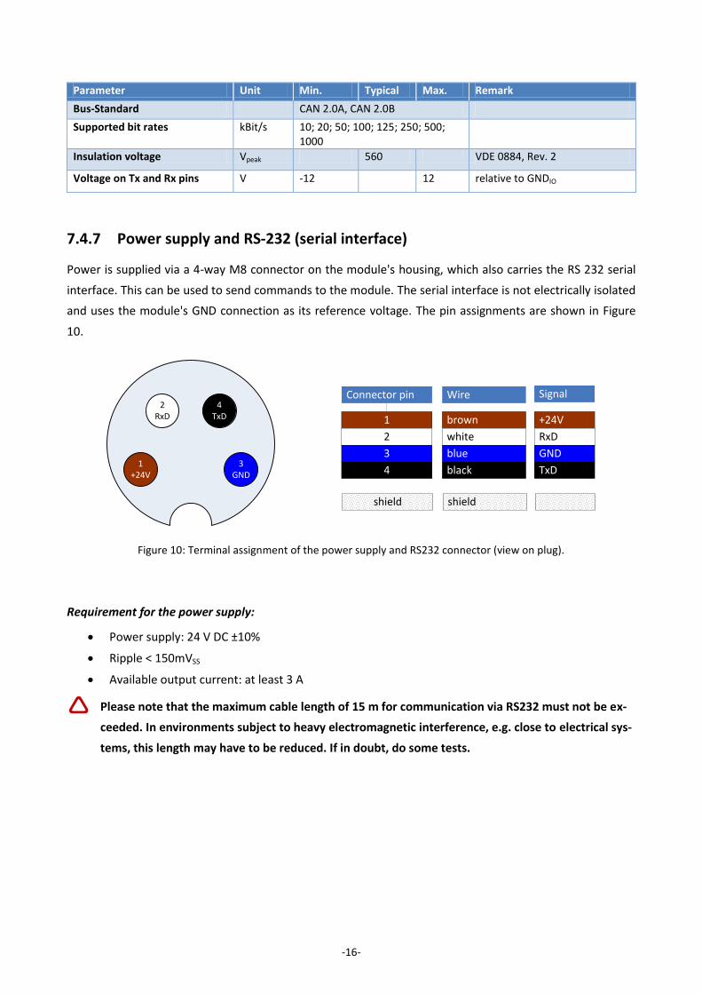
7.4.7 Power supply and RS-232 (serial interface)
Power is supplied via a 4-way M8 connector on the module's housing, which also carries the RS 232 serial
interface. This can be used to send commands to the module. The serial interface is not electrically isolated
and uses the module's GND connection as its reference voltage. The pin assignments are shown in Figure
10.
Requirement for the power supply:
Power supply: 24 V DC ±10%
Ripple < 150mVSS
Available output current: at least 3 A
Please note that the maximum cable length of 15 m for communication via RS232 must not be ex-
ceeded. In environments subject to heavy electromagnetic interference, e.g. close to electrical sys-
tems, this length may have to be reduced. If in doubt, do some tests.
WireConnector pin Signal
brown1 +24V
white2 RxD
blue3 GND
black4 TxD
shieldshield
1+24V
3GND
2RxD
4TxD
Figure 10: Terminal assignment of the power supply and RS232 connector (view on plug).
-17-
Interface specification RS-232:
Parameter Unit Min. Typical Max. Remark
Output level (TxD) V ±5.0 ±5.7 Load resistance = 3kΩ
Input voltage range (RxD) V -30 30 relative to GND
High input level V -30 1,3 relative to GND
Low input level V 2.4 30 relative to GND
Supported bit rates kBit/s 1,2; 2,4; 4,8; 9,6; 19,2; 38,4; 57,6; 115,2; 230,4; 460,8
Data format 8 Data bits, no parity, 1 stop bit (8n1)
Flow control none
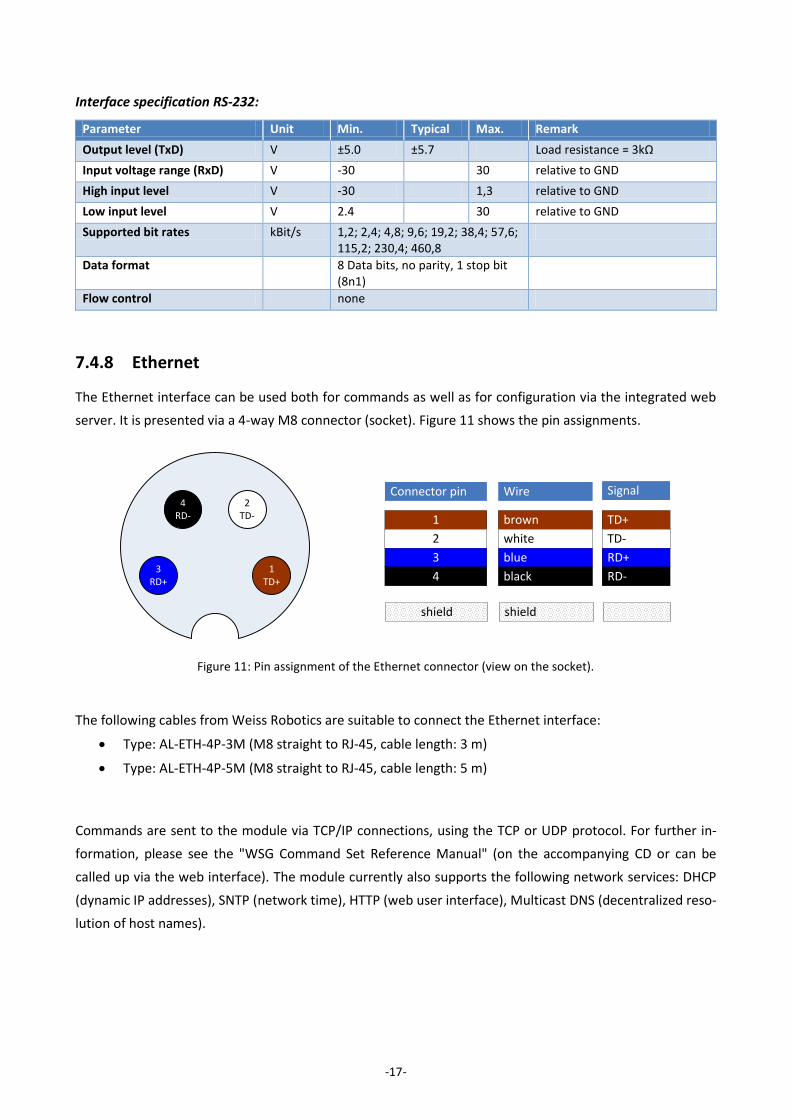
7.4.8 Ethernet
The Ethernet interface can be used both for commands as well as for configuration via the integrated web
server. It is presented via a 4-way M8 connector (socket). Figure 11 shows the pin assignments.
The following cables from Weiss Robotics are suitable to connect the Ethernet interface:
Type: AL-ETH-4P-3M (M8 straight to RJ-45, cable length: 3 m)
Type: AL-ETH-4P-5M (M8 straight to RJ-45, cable length: 5 m)
Commands are sent to the module via TCP/IP connections, using the TCP or UDP protocol. For further in-
formation, please see the "WSG Command Set Reference Manual" (on the accompanying CD or can be
called up via the web interface). The module currently also supports the following network services: DHCP
(dynamic IP addresses), SNTP (network time), HTTP (web user interface), Multicast DNS (decentralized reso-
lution of host names).
WireConnector pin Signal
brown1 TD+
white2 TD-
blue3 RD+
black4 RD-
shieldshield
1TD+
3RD+
2TD-
4RD-
Figure 11: Pin assignment of the Ethernet connector (view on the socket).
-18-
Interface specification:
Parameter Unit Min. Typical Max. Remark
Transmission standard IEEE 802.3
Communication standard TCP/IP (IPv4)
Transmission speed MBit/s 10; 100 Auto-negotiated
Transmission type Half duplex
Auto-MDIX yes
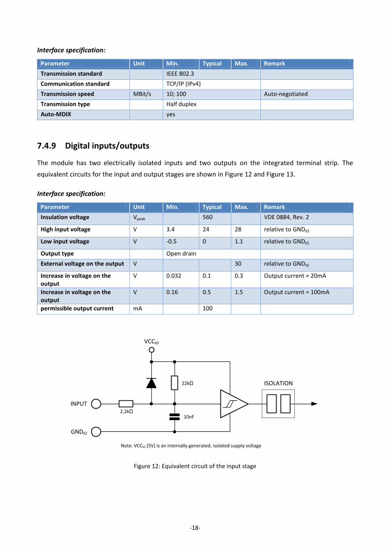
7.4.9 Digital inputs/outputs
The module has two electrically isolated inputs and two outputs on the integrated terminal strip. The
equivalent circuits for the input and output stages are shown in Figure 12 and Figure 13.
Interface specification:
Parameter Unit Min. Typical Max. Remark
Insulation voltage Vpeak 560 VDE 0884, Rev. 2
High input voltage V 3.4 24 28 relative to GNDIO
Low input voltage V -0.5 0 1.1 relative to GNDIO
Output type Open drain
External voltage on the output V 30 relative to GNDIO
Increase in voltage on the output
V 0.032 0.1 0.3 Output current = 20mA
Increase in voltage on the output
V 0.16 0.5 1.5 Output current = 100mA
permissible output current mA 100
INPUT
GNDIO
2,2kΩ
VCCIO
ISOLATION22kΩ
10nF
Note: VCCIO (5V) is an internally generated, isolated supply voltage
Figure 12: Equivalent circuit of the input stage
-19-
Inductive loads can damage the output stages. Wire a protective diode antiparallel to the output.
7.4.10 Base jaw with sensor port
The module has an integrated sensor port in each of the base jaws which makes it easy to connect intelli-
gent gripper fingers. The sensor port makes the following interfaces available:
UART (LVTTL levels)
SPI (LVTTL levels)
Analog input (0 to 2,5 V)
The sensor port supports the automatic configuration of the connected fingers. To use this function, a con-
figuration memory must be integrated into the fingers. All of the intelligent fingers offered by Weiss Robot-
ics for this gripper (e.g. force measurement finger WSG-FMF) already have this memory integrated and are
completely configured, so that you just have to fit this finger to the module. The fingers will then be auto-
matically detected the next time the system starts. The sensor port supplies an operating voltage of 5 V
±10% at max. 200 mA. The supply voltage is protected against short circuits and can be switched on and off
from the gripper control system. A short circuit in the supply voltage will trigger an error state which must
be acknowledged.
The power supply from the sensor port is not suitable to supply actuators.
The gripper control system may be destroyed by excess voltage on the sensor port pins.
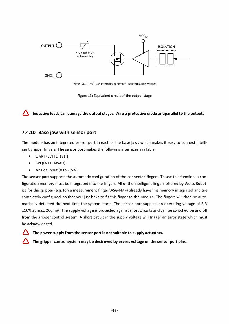
OUTPUT
GNDIO
PTC Fuse, 0,1 Aself-resetting
VCCIO
ISOLATION
Note: VCCIO (5V) is an internally generated, isolated supply voltage
Figure 13: Equivalent circuit of the output stage
-20-
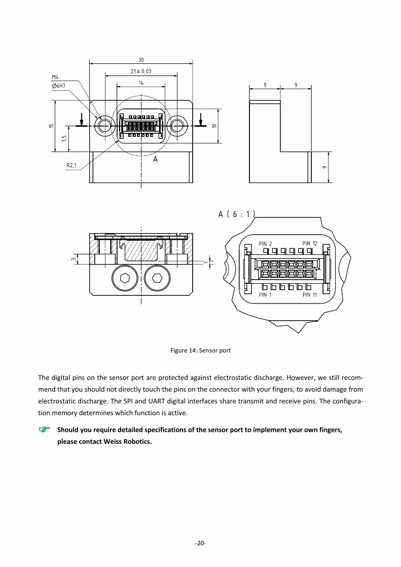
The digital pins on the sensor port are protected against electrostatic discharge. However, we still recom-
mend that you should not directly touch the pins on the connector with your fingers, to avoid damage from
electrostatic discharge. The SPI and UART digital interfaces share transmit and receive pins. The configura-
tion memory determines which function is active.
Should you require detailed specifications of the sensor port to implement your own fingers,
please contact Weiss Robotics.
Figure 14: Sensor port
-21-
Matching centering sleeves
Matching centering sleeves are supplied with the fingers. For your own designs or as a spare part, please
use the centering sleeves which are available as accessories under item no. ZH-6.0-5.35, described as: cen-
tering sleeve 06.0 x 5.35 (outer diameter: 6h6).
Sensor port connector
Made by: ERNI, type: SMC-B-12 (terminal strip), part number: 154805
Counterpiece: SMC-Q-12 (male, low-profile connector), part number: 154818
Sensor port connector pin assignments
Pin number Name Direction Function
1 MOSI/TXD OUT SPI/UART: Transmit data from the manual controller
2 nSSEL OUT Only SPI: A low signal selects the slave
3 AN IN Analog input. Voltage range: 0 to 2.5 V
4 SCLK OUT Only SPI: Clock for transmit and receive data
5 CFG-SDA I/O Configuration bus – data line
6 MISO/RXD IN SPI/UART: Received data
7 CFG-SCL OUT Configuration bus – clock line
8 NC - not connected
9 +5V OUT Operating voltage output 5V/200mA max.
10 +5V
11 GND OUT Mass
12 GND
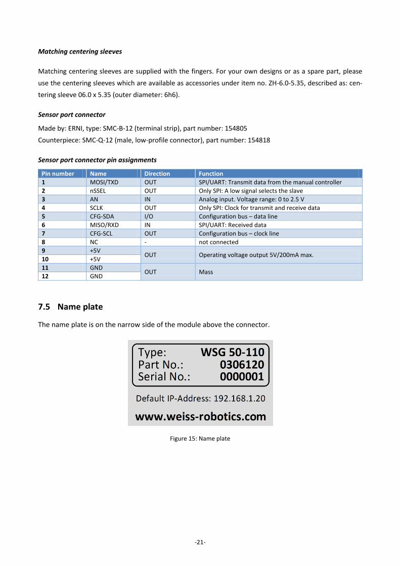
7.5 Name plate
The name plate is on the narrow side of the module above the connector.
Figure 15: Name plate
-22-
8 Installation
8.1 Installation instructions
Risk of injury because of electrical energy!
Warning: Risk of injury when the machine/system moves unexpectedly!
Remove energy supplies during all maintenance work and adjustments.
8.2 Mechanical connection
The threads which can be used to mount the module and the centering holes are shown in Figure 16. The
module has both M3 and M6 threads for fixing on the rear of ist housing, as well as 6 mm centering holes.
The M6 threads together with the centering holes form part of the 50 mm ISO standard flange for industrial
robots. When in holding mode, the module constantly adjusts the gripping force, to ensure a constant grip-
ping force. The surfaces which are screwed together must be capable of dissipating the resulting heat.
Risk of burns from hot surfaces!
Please ensure that the thermal coupling is good, especially if the module is to apply high gripping
forces over longer periods of time. There is a risk of overheating!
Prevent exposure to external sources of heat, such as from your robot’s pan-tilt unit, as this can
reduce the module’s performance. Poor dissipation of heat or exposure to additional heat will re-
quire the gripping force to be reduced.
To ensure fault-free operation and to minimize the radiation of electromagnetic interference
(EMC) the module’s housing must be properly earthed.

-23-
Do not exceed maximum torque: M3 threads = 1.0 Nm MAX, M6 threads = 3.0 Nm MAX
8.3 Electrical Connection
As supplied, the module is configured so that the M8 connector carries both the power as well as the logic
parts for the integrated gripper control system. If your application requires the power and logic parts to be
separated, for instance if you would like to use an external relay to ensure that the gripping force is safely
switched off (cf. "safe torque off", STO), then the power and logic parts can be supplied separately. The
equivalent circuit for the power supply is shown in Figure 17. The power and logic supply are not electrically
isolated so they must use the same power supply unit. The common supply of load and logic is shown in
Figure 18. If the supply to the load is to be switchable in operation, then the connection can be arranged as
shown in Figure 19.
Figure 16: Mechanical connection

-24-
+24V DRIVE
GND
+24V LOGIC
Control Stage Power Stage M
Gripper Module
Figure 17: Equivalent circuit for the power supply
Gripper Module
+24V DRIVE
+24V LOGIC
GND
Power Supply
GND
24V / 5A
Figure 18: Connection type common supply to load and logic
Gripper Module
+24V DRIVE
+24V LOGIC
GND
Power Supply
GND
24V / 5A
Force off
Figure 19: Connection type supply to load separate from supply to logic
-25-
If load and logic are operated separately, always use the same power supply.
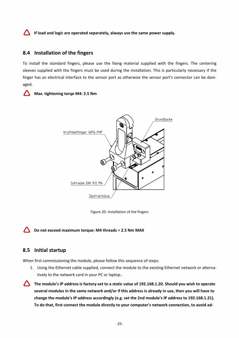
8.4 Installation of the fingers
To install the standard fingers, please use the fixing material supplied with the fingers. The centering
sleeves supplied with the fingers must be used during the installation. This is particularly necessary if the
finger has an electrical interface to the sensor port as otherwise the sensor port's connector can be dam-
aged.
Max. tightening torqe M4: 2.5 Nm
Do not exceed maximum torque: M4 threads = 2.5 Nm MAX
8.5 Initial startup
When first commissioning the module, please follow this sequence of steps:
1. Using the Ethernet cable supplied, connect the module to the existing Ethernet network or alterna-
tively to the network card in your PC or laptop..
The module's IP address is factory-set to a static value of 192.168.1.20. Should you wish to operate
several modules in the same network and/or if this address is already in use, then you will have to
change the module's IP address accordingly (e.g. set the 2nd module's IP address to 192.168.1.21).
To do that, first connect the module directly to your computer's network connection, to avoid ad-
Figure 20: Installation of the fingers
-26-
dress conflicts in the network. For more information about changing the IP address, please see
chapter 8.6.
To directly operate the module on your computer's network connection, you may have to alter
your computer's network configuration. If in doubt, contact your system administrator.
2. Connect your module with the power supply (24 V, 3 A).
3. The module will now start up. The indicator for the operating state will light up blue and after
about 5 seconds it will start flashing quickly blue. This signals that the module is booting. After
about 15 seconds the indicator will slowly flash white. The module is ready for use.
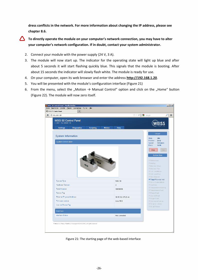
4. On your computer, open its web browser and enter the address http://192.168.1.20.
5. You will be presented with the module’s configuration interface (Figure 21)
6. From the menu, select the „Motion → Manual Control“ option and click on the „Home“ button
(Figure 22). The module will now zero itself.
Figure 21: The starting page of the web-based interface

-27-
7. Once the movements associated with zeroing have finished, for test purposes, you can move the
module via the web interface. For this, select the movement parameters about the adjuster and
then click on the "Move" button.
Important: The module must be zeroed tob e able to execute movement commands.
8. Other steps which you should take during the commissioning:
a. Call up the “Diagnostics → System State“ page, to check the module’s supply voltage
b. On the „Settings → Command Interface“ page, select the interface on which your module is
to be operated.
c. If necessary, on the „Settings → Motion Configuration“ page enable automatic zeroing dur-
ing startup („Homing on Startup“).
d. On the „Settings → System“ page, create a user with corresponding rights and activate the
web interface’s security function to prevent changes to your setting by unauthorized per-
sons.
Figure 22: „Manual Control“ configuration page
-28-
8.6 Changing the IP address and using DHCP
To change the module's IP address, in the web interface, select the "Settings → Network" menu option.
Adjust the IP address, subnet masks and any gateway or DNS server addresses for your local network and
confirm the changes by clicking on the "Apply" button.
After changing the network configuration you will have to restart the module.
To use addresses dynamically assigned via DHCP, check the corresponding box. In this case the module will
automatically take its network configuration from a DHCP server..
Please note that if you use DHCP to dynamically allocate IP addresses, there is no integrated way
of finding out what IP address has been allocated. This is why the DHCP server should be config-
ured so that the module is issued with an IP address which is known in advance.
Please contact your network administrator for more information.
9 Operation
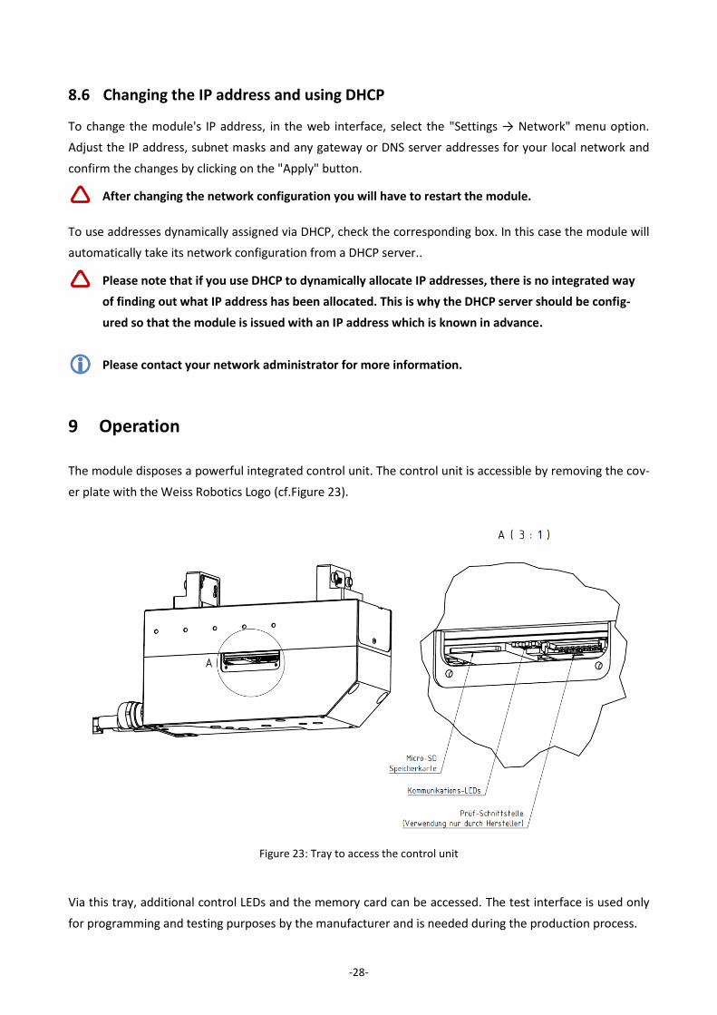
The module disposes a powerful integrated control unit. The control unit is accessible by removing the cov-
er plate with the Weiss Robotics Logo (cf.Figure 23).
Via this tray, additional control LEDs and the memory card can be accessed. The test interface is used only
for programming and testing purposes by the manufacturer and is needed during the production process.
Figure 23: Tray to access the control unit
-29-
9.1 Operating software
The software needed to operate the module is already installed in the unit.
To guarantee proper operation, the latest version of the firmware should always be installed in the
module.
The latest firmware can be downloaded free of charge from www.weiss-robotics.de. The module
has to be registered before download.
9.2 Memory card
The module’s control unit is equipped with a tray for Micro SD memory cards. Although all popular types
(SD and SDHC) are supported, the use of the following card type is recommended:
Micro SD card:
Manufacturer: SANDISK, Type: SDSDQM-002G-B35, Capacity: 2 GB
The memory card contains the following data:
the software needed to operate the module
configuration data
documentation and software tools (to be downloaded from the web interface)
scripts and other user-specific data in the /user directory
The factory-installed card has a capacity of 2 GB. The required software to operate the module is already
installed. User-specific data and scripts can be saved in the subdirectory “user”. Please do not change any
files outside of this subdirectory, as this may influence the operation of the module and a proper operation
cannot be guaranteed any more.
The memory card and the installed software are necessary to operate the module. If you are con-
sidering to change the SD card, please copy the contents of the original card to the new card with
an appropriate card reader.
9.3 Boot process
The module has a boot loader, which loads and runs the unit’s software from the memory card when the
unit is powered up. The indicator for the operating state will light up blue during this. If there is an error,
the indicator will light up red for 5 seconds. After this the boot loader will automatically be restarted. This
will continue until the firmware can be loaded correctly.
-30-
If there is a VT100 compatible terminal conected tot he serial interface, the boot loader prints ist status
messages to this interface and the indicator will turn to violet. The terminal adapter must be configured to
115200 bps, 8 data bits, no parity, 1 stop bit.
To identify the terminal adapter, the module will output the byte sequence „ESC [?1;“during
startup with the interface settings described above. If using the serial interface as command inter-
face, the host application must be configured in a way that doesn’t cause any problems when
receiveing this byte sequence.
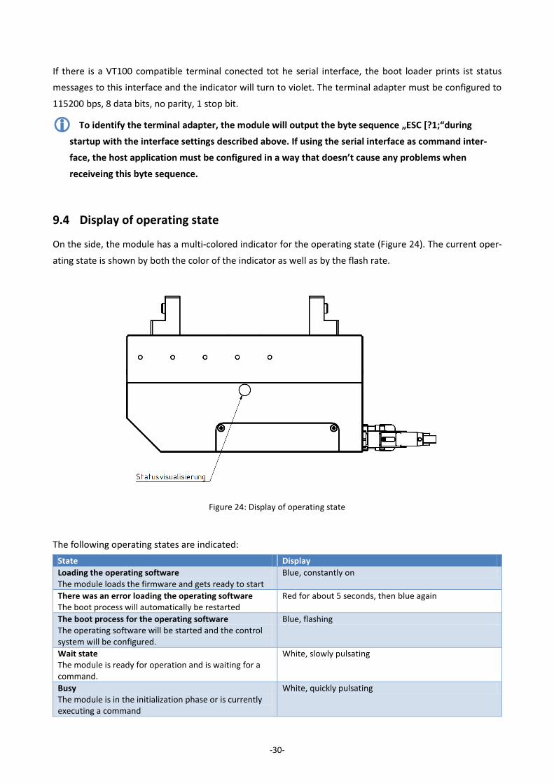
9.4 Display of operating state
On the side, the module has a multi-colored indicator for the operating state (Figure 24). The current oper-
ating state is shown by both the color of the indicator as well as by the flash rate.
The following operating states are indicated:
State Display
Loading the operating software The module loads the firmware and gets ready to start
Blue, constantly on
There was an error loading the operating software The boot process will automatically be restarted
Red for about 5 seconds, then blue again
The boot process for the operating software The operating software will be started and the control system will be configured.
Blue, flashing
Wait state The module is ready for operation and is waiting for a command.
White, slowly pulsating
Busy The module is in the initialization phase or is currently executing a command
White, quickly pulsating
Figure 24: Display of operating state

-31-
Executing a script A script is being executed by the control system.
Green, quickly pulsating
Warning One or more parameters have reached warning limits. Please check the system’s status via its web interface.
Yellow, quickly pulsating
Command received with no errors The module has received an error-free command
Green, pulses once
Error carrying out a command An error has occurred while receiving or executing a command.
Red, pulses once
Loading the operating software The module loads the firmware and gets ready to start
Blue, constantly on
Critical fault An error has occurred (e.g. excess temperature, loss of communications, etc.). This error must be acknowl-edged before the module can process new commands to move.
Red, pulses quickly
Critical software fault A serious error has occurred and the execution of the software in the unit has been stopped. The module will restart after a short time.
Red, flash code 2x short, long pause
More LEDs indicating SD card and communication activity can be found next to the SD card slot under the
cover plate with the Weiss Robotics logo (cf.Figure 25). ). A constant lightning of the respective LED indi-
cates that the interface is active. The LEDs flash in the rhythm of the interface activity or data traffic.
Ein Dauerleuchten der entsprechenden Leuchtdiode zeigt an, dass die entsprechende Schnittstelle aktiviert
ist. Die Leuchtdioden flackern im Rhythmus der Schnittstellenaktivität bzw. des Datenverkehrs.
Figure 25: Kommunikations-LEDs
-32-
9.5 Status word and gripper state
The module’s current state can be called up at any time via the status word and the gripper state.
9.5.1 Status word
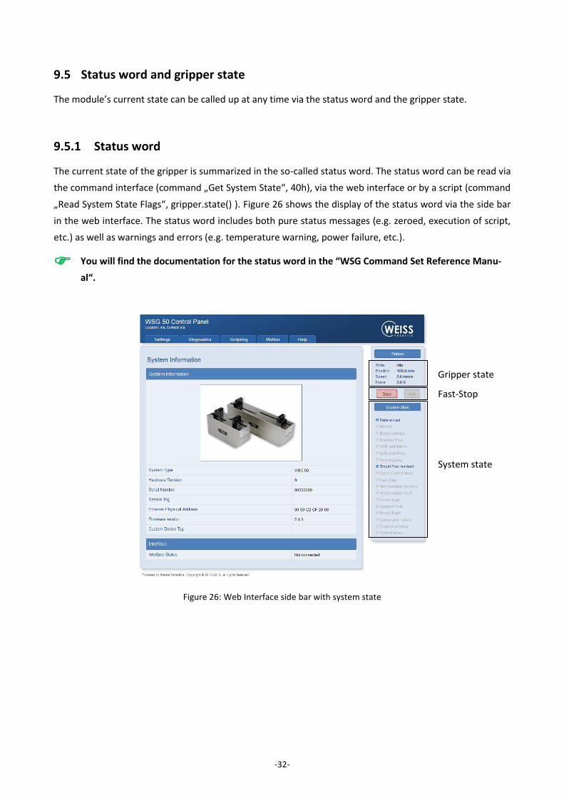
The current state of the gripper is summarized in the so-called status word. The status word can be read via
the command interface (command „Get System State“, 40h), via the web interface or by a script (command
„Read System State Flags“, gripper.state() ). Figure 26 shows the display of the status word via the side bar
in the web interface. The status word includes both pure status messages (e.g. zeroed, execution of script,
etc.) as well as warnings and errors (e.g. temperature warning, power failure, etc.).
You will find the documentation for the status word in the “WSG Command Set Reference Manu-
al“.
Figure 26: Web Interface side bar with system state
System state
Fast-Stop
Gripper state
-33-
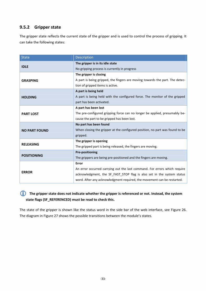
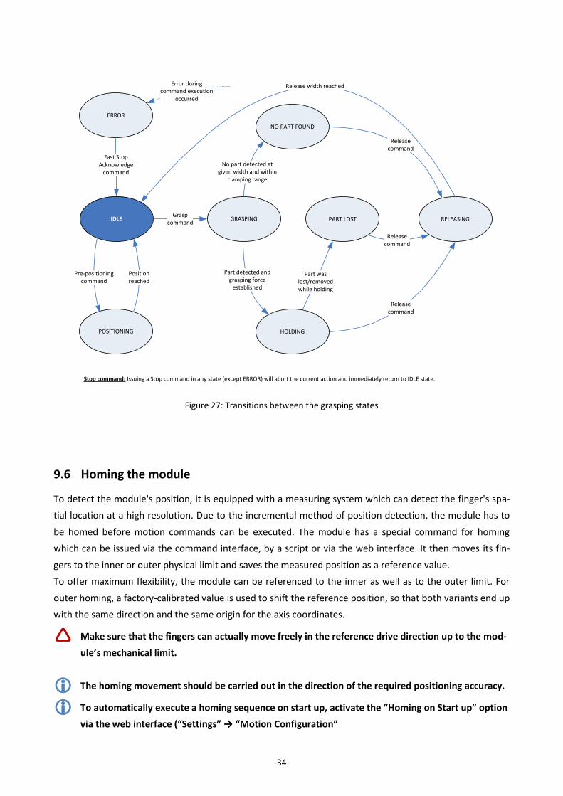
9.5.2 Gripper state
The gripper state reflects the current state of the gripper and is used to control the process of gripping. It
can take the following states:
State Description
IDLE The gripper is in its idle state
No gripping process is currently in progress
GRASPING
The gripper is closing
A part is being gripped, the fingers are moving towards the part. The detec-
tion of gripped items is active.
HOLDING
A part is being held
A part is being held with the configured force. The monitor of the gripped
part has been activated.
PART LOST
A part has been lost
The pre-configured gripping force can no longer be applied, presumably be-
cause the part to be gripped has been lost.
NO PART FOUND
No part has been found
When closing the gripper at the configured position, no part was found to be
gripped.
RELEASING The gripper is opening
The gripped part is being released, the fingers are moving.
POSITIONING Pre-positioning
The grippers are being pre-positioned and the fingers are moving.
ERROR
Error
An error occurred carrying out the last command. For errors which require
acknowledgment, the SF_FAST_STOP flag is also set in the system status
word. After any acknowledgment required, the movement can be restarted.
The gripper state does not indicate whether the gripper is referenced or not. Instead, the system
state flags (SF_REFERENCED) must be read to check this.
The state of the gripper is shown like the status word in the side bar of the web interface, see Figure 26.
The diagram in Figure 27 shows the possible transitions between the module’s states.
-34-
9.6 Homing the module
To detect the module's position, it is equipped with a measuring system which can detect the finger's spa-
tial location at a high resolution. Due to the incremental method of position detection, the module has to
be homed before motion commands can be executed. The module has a special command for homing
which can be issued via the command interface, by a script or via the web interface. It then moves its fin-
gers to the inner or outer physical limit and saves the measured position as a reference value.
To offer maximum flexibility, the module can be referenced to the inner as well as to the outer limit. For
outer homing, a factory-calibrated value is used to shift the reference position, so that both variants end up
with the same direction and the same origin for the axis coordinates.
Make sure that the fingers can actually move freely in the reference drive direction up to the mod-
ule’s mechanical limit.
The homing movement should be carried out in the direction of the required positioning accuracy.
To automatically execute a homing sequence on start up, activate the “Homing on Start up” option
via the web interface (“Settings” → “Motion Configuration”
IDLE PART LOST
NO PART FOUND
RELEASING
POSITIONING
ERROR
Pre-positioningcommand
Grasp command
Position reached
Part detected and grasping force
established
No part detected at given width and within
clamping range
GRASPING
Releasecommand
Release width reached
Part was lost/removed while holding
Release command
Releasecommand
HOLDING
Fast Stop Acknowledge
command
Error during command execution
occurred
Stop command: Issuing a Stop command in any state (except ERROR) will abort the current action and immediately return to IDLE state.
Figure 27: Transitions between the grasping states

-35-
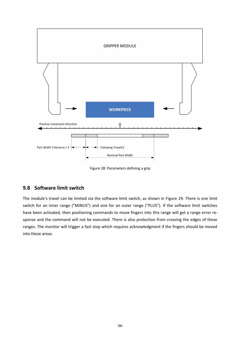
9.7 Gripping, part detection and grip monitoring
The module is equipped with an integrated detector for parts to be gripped and a grip monitor, which al-
lows reliable handling even for difficult parts without the use of external sensors. To configure these func-
tions, the following parameters are available on the web interface (“Settings“→ “Motion Configuration“):
Parameter Description
Part Width Tolerance
The tolerance of the specified nominal gripper width which is sent to the
module with the grasp command. This is measured as the relative gap be-
tween two fingers moving towards one another.
Clamping travel
If a part to be gripped has been detected, the module will attempt to apply
the required gripping force by moving the fingers within this range. This is
measured as the relative gap between two fingers moving towards one an-
other.
clarifies the function of these two parameters. A grip is only valid (which means it doesn't create an error)
if the detected width of the part lies within the hatched area consisting of the part width tolerance and the
clamping travel. If no part is detected, then the gripper state will change to "NO PART FOUND". If a contact
is detected outside of the defined range, this will be detected as an axis block and the gripper's state will
change to "ERROR".
The detector of parts to be gripped and the grip monitor are not running in pre-position mode
("Pre-position" command).
Damage to the gripper is possible due to insufficient lubrication (dry-running) if the gripper con-
stantly goes through short movements. → every 1000 movements (or at least once per day) the
gripper should be moved through its full range of travel.
For soft parts to be gripped, it may be necessary to increase the clamping travel.
Setting the part width tolerance to the full range of movement of the module (maximum settings)
will deactivate the detection of axis blocking when gripping.
-36-
GRIPPER MODULE
WORKPIECE
Nominal Part Width
Part Width Tolerance / 2
0
Clamping Travel/2
Positive movement direction
Figure 28: Parameters defining a grip
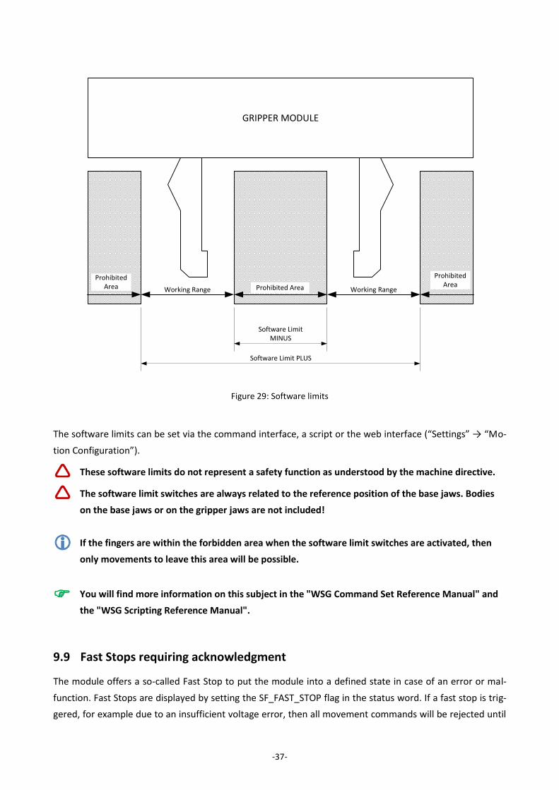
9.8 Software limit switch
The module’s travel can be limited via the software limit switch, as shown in Figure 29. There is one limit
switch for an inner range ("MINUS") and one for an outer range ("PLUS"). If the software limit switches
have been activated, then positioning commands to move fingers into this range will get a range error re-
sponse and the command will not be executed. There is also protection from crossing the edges of these
ranges. The monitor will trigger a fast stop which requires acknowledgment if the fingers should be moved
into these areas.
-37-
Figure 29: Software limits
The software limits can be set via the command interface, a script or the web interface (“Settings” → “Mo-
tion Configuration”).
These software limits do not represent a safety function as understood by the machine directive.
The software limit switches are always related to the reference position of the base jaws. Bodies
on the base jaws or on the gripper jaws are not included!
If the fingers are within the forbidden area when the software limit switches are activated, then
only movements to leave this area will be possible.
You will find more information on this subject in the "WSG Command Set Reference Manual" and
the "WSG Scripting Reference Manual".
9.9 Fast Stops requiring acknowledgment
The module offers a so-called Fast Stop to put the module into a defined state in case of an error or mal-
function. Fast Stops are displayed by setting the SF_FAST_STOP flag in the status word. If a fast stop is trig-
gered, for example due to an insufficient voltage error, then all movement commands will be rejected until
GRIPPER MODULE
Software Limit MINUS
Software Limit PLUS
Working Range Working RangeProhibited Area
Prohibited Area
Prohibited Area
-38-
the error is acknowledged and any fault condition has been cleared, with corresponding error codes being
returned (access denied).
If the module is in Fast Stop state, power will be removed from the drives but the position reference will be
retained.
The error can be acknowledged both via the command interface (the command is: Acknowledging a Fast
Stop or fault Condition, 24h) as well as manually by clicking on the "Ack" button in the side bar of the web
interface (see Figure 26). Fast stops are recorded in the module's event log (see chapter 9.10).
Loss of gripping power on fast stop!
The fast stop does not represent a safety function as understood by the machine directive.
A fast stop can also be triggered via the command interface, by a script or manually via the web
interface.
For more information, please refer to the "WSG Scripting Reference Manual".
9.10 Log memory
The module has a non-volatile log memory in which important events are recorded. The events are saved
with a timestamp (if no time of day is available via the network, then the time in milliseconds since the
system was started will be used) and are displayed in chronological order. If the memory is full, the oldest
events will be overwritten. The log memory can be read out via the web interface („Diagnostics“ → „System
State“). It can also be copied to the SD card to be downloaded from the web interface via the integrated
file manager:
1. Open the web interface
2. In the menu, go to “Diagnostics” → “System Information”
3. Click the button „Dump“ below the system log. A file named „logfile.txt“ is created in the user di-
rectory on the SD card.
4. Download the file with the file manager. Choose “Scripting” → “File Manager” from the menu. Se-
lect the file and start downloading by clicking the button .
5.
9.11 Thermal monitor
To protect the module from overheating, its housing is constantly monitored during operation. The current
housing temperature can be checked both via the web interface as well as the command interface.
If the temperature measured exceeds the limit of 65 °C, then a temperature warning will be issued. From a
housing temperature of 70 °C the module will change into temperature error mode and will switch the
power output stage off via a fast stop. This temperature error must be acknowledged via the "Fast Stop
Acknowledge" command.
-39-
Temperature warnings and errors are recorded in the module's event log (see chapter 9.10).
Loss of gripping force on temperature error!
This error can only be acknowledged if there is no longer a temperature error.
The command to read out the current housing temperature and the command to acknowledge the
Fast Stop via the command interface are documented in the "WSG Command Set Reference Manu-
al".
9.12 Monitoring the drive current
The drive current is continuously measured and monitored during operation. An integrated motor model is
used to check whether the drive is being overloaded or not. In this case, the power output stage will be
switched off via a fast stop and a "current fault" will be displayed. The current error must be acknowledged.
This can either be done via the web interface or via the command interface using the "Fast Stop
Acknowledge“ command. Current errors are recorded in the module's event log (see chapter 9.10).
Loss of gripping force when there is a current error!
This error can only be acknowledged if there is no longer a current error.
For the documentation of the command to acknowledge the "Fast Stop" via the command inter-
face, see the "WSG Command Set Reference Manual".

-40-
9.13 Monitoring the supply voltage
To ensure the correct functioning of the module, the supply voltage to its power section is continuously
monitored. If the measured voltage is outside a defined range, a warning or an error will be issued. The
following limits apply:
Threshold Consequence
Supply Voltage <= 20 V
Low voltage fault
SF_POWER_FAULT will be set in the system’s status word and the status indi-
cator will show the error state.
Supply Voltage <= 22 V
Low voltage warning
SF_POWER_WARNING will be set in the system’s status word and the status
indicator will show the warning state.
Supply Voltage >= 26 V
Excess voltage warning
SF_POWER_WARNING will be set in the system’s status word and the status
indicator will show the warning state.
Supply Voltage >= 28 V
Excess voltage error
SF_POWER_FAULT will be set in the system’s status word and the indicator
will show the error state.
Hysteresis is used to prevent the states chattering to and fro. If there is a voltage error, the power output
stage will be switched off using a Fast Stop and a voltage error will be indicated. Acknowledging the Fast
Stop is possible only if the operating voltage is back in its allowed range. Acknowledging can be done either
via the web interface or via the command interface by using the "Fast Stop Acknowledge" command.
Loss of gripper force following an error due to the voltage being too high or too low!
The low voltage fault will also be triggered if the power supply is interrupted when switching the
force off, e.g. via an emergency stop relay.
This error can only be acknowledged if there is no longer a high/low voltage error.
For the documentation of the system status word and the command to acknowledge the "Fast
Stop" via the command interface, see the "WSG Command Set Reference Manual".
9.14 Overdrive Mode
The module is equipped with an overdrive mode, in which for grasping cycles with short holding times
(max. 2 seconds) and long opening times (more than 10 seconds) grasping forces higher than the nominal
grasping force can be achieved. The overdrive mode must be activated using a special command on the
command interface and will be displayed in the system state („Overdrive Mode“).
Activating the overdrive mode will be noted in the system log (see chapter 9.10).
-41-
Despite to thermal protection, the module can be damaged when overloading. For further infor-
mation, please contact our technical distributor.
For a documentation of the overdrive mode, please check the „WSG Command Set Reference
Manual“.
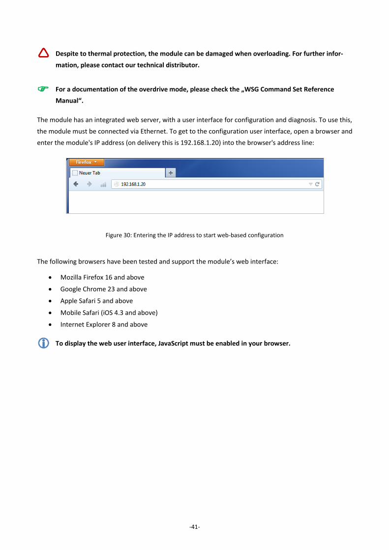
The module has an integrated web server, with a user interface for configuration and diagnosis. To use this,
the module must be connected via Ethernet. To get to the configuration user interface, open a browser and
enter the module's IP address (on delivery this is 192.168.1.20) into the browser's address line:
Figure 30: Entering the IP address to start web-based configuration
The following browsers have been tested and support the module’s web interface:
Mozilla Firefox 16 and above
Google Chrome 23 and above
Apple Safari 5 and above
Mobile Safari (iOS 4.3 and above)
Internet Explorer 8 and above
To display the web user interface, JavaScript must be enabled in your browser.
-42-
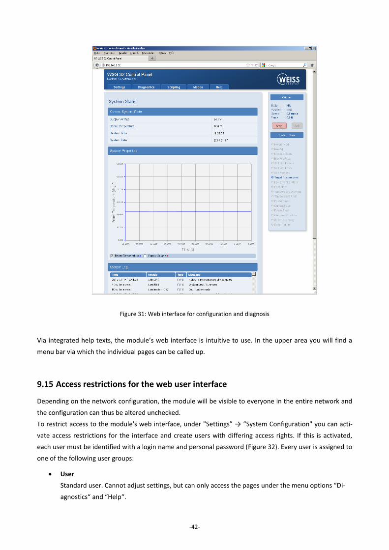
Via integrated help texts, the module’s web interface is intuitive to use. In the upper area you will find a
menu bar via which the individual pages can be called up.
9.15 Access restrictions for the web user interface
Depending on the network configuration, the module will be visible to everyone in the entire network and
the configuration can thus be altered unchecked.
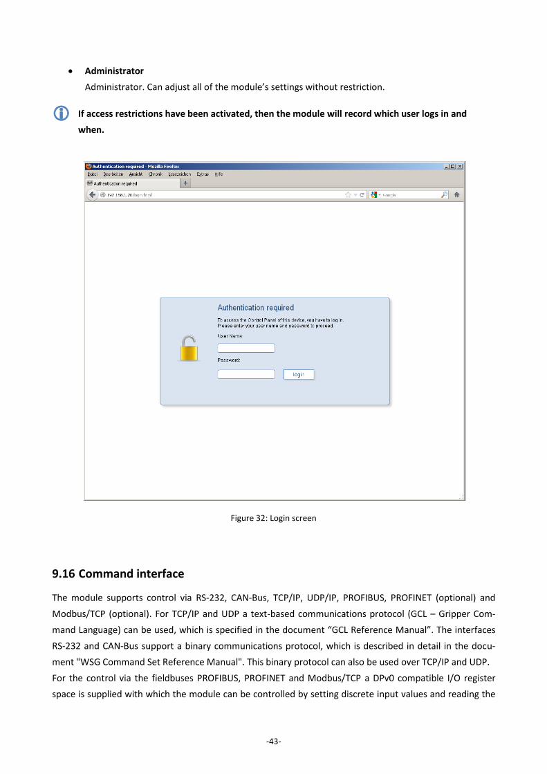
To restrict access to the module's web interface, under "Settings” → “System Configuration" you can acti-
vate access restrictions for the interface and create users with differing access rights. If this is activated,
each user must be identified with a login name and personal password (Figure 32). Every user is assigned to
one of the following user groups:
User
Standard user. Cannot adjust settings, but can only access the pages under the menu options “Di-
agnostics“ and “Help“.
Figure 31: Web interface for configuration and diagnosis
-43-
Administrator
Administrator. Can adjust all of the module’s settings without restriction.
If access restrictions have been activated, then the module will record which user logs in and
when.
9.16 Command interface
The module supports control via RS-232, CAN-Bus, TCP/IP, UDP/IP, PROFIBUS, PROFINET (optional) and
Modbus/TCP (optional). For TCP/IP and UDP a text-based communications protocol (GCL – Gripper Com-
mand Language) can be used, which is specified in the document “GCL Reference Manual”. The interfaces
RS-232 and CAN-Bus support a binary communications protocol, which is described in detail in the docu-
ment "WSG Command Set Reference Manual". This binary protocol can also be used over TCP/IP and UDP.
For the control via the fieldbuses PROFIBUS, PROFINET and Modbus/TCP a DPv0 compatible I/O register
space is supplied with which the module can be controlled by setting discrete input values and reading the
Figure 32: Login screen
-44-
module’s current output parameters. For further information, please refer to the “WSG Fieldbus Interface
Manual”.
The command interface is selected and configured via the module's web interface, via the menu option
"Settings” → “Command Interface".
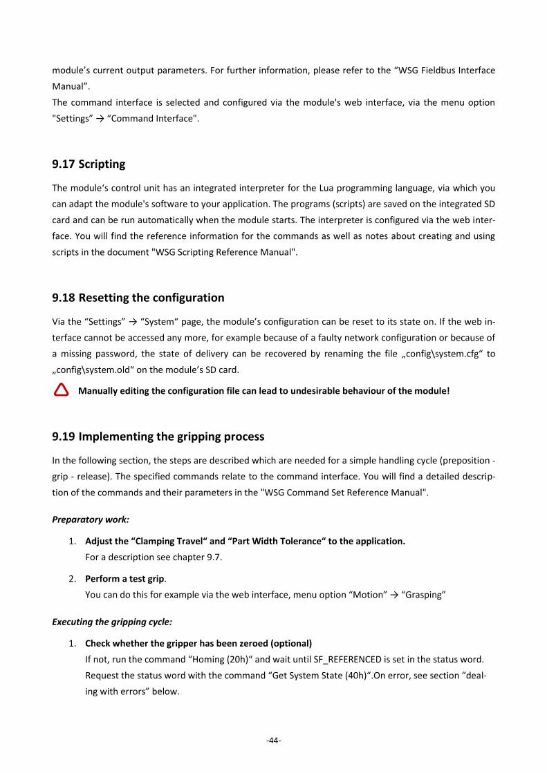
9.17 Scripting
The module‘s control unit has an integrated interpreter for the Lua programming language, via which you
can adapt the module's software to your application. The programs (scripts) are saved on the integrated SD
card and can be run automatically when the module starts. The interpreter is configured via the web inter-
face. You will find the reference information for the commands as well as notes about creating and using
scripts in the document "WSG Scripting Reference Manual".
9.18 Resetting the configuration
Via the “Settings” → “System“ page, the module’s configuration can be reset to its state on. If the web in-
terface cannot be accessed any more, for example because of a faulty network configuration or because of
a missing password, the state of delivery can be recovered by renaming the file „config\system.cfg“ to
„config\system.old“ on the module’s SD card.
Manually editing the configuration file can lead to undesirable behaviour of the module!
9.19 Implementing the gripping process
In the following section, the steps are described which are needed for a simple handling cycle (preposition -
grip - release). The specified commands relate to the command interface. You will find a detailed descrip-
tion of the commands and their parameters in the "WSG Command Set Reference Manual".
Preparatory work:
1. Adjust the “Clamping Travel“ and “Part Width Tolerance“ to the application.
For a description see chapter 9.7.
2. Perform a test grip.
You can do this for example via the web interface, menu option “Motion” → “Grasping”
Executing the gripping cycle:
1. Check whether the gripper has been zeroed (optional)
If not, run the command “Homing (20h)“ and wait until SF_REFERENCED is set in the status word.
Request the status word with the command “Get System State (40h)“.On error, see section “deal-
ing with errors” below.
-45-
2. Pre-position finger
Execute the command "Pre-Position Fingers (21h)". Parameters: Opening width and speed. The
gripper state changes to "POSITIONING". Wait until the gripper state is "IDLE". Request the gripper
state with the command "Get Grasping State (41h)".
3. Execute the grip
Command "Grasp Part (25h)". Parameters: Nominal gripping width, gripping speed, gripping force.
The gripper state changes to "GRASPING". Wait until the gripper state is "HOLDING". Deal with er-
rors if gripper state is "NO PART FOUND" or "ERROR".
4. Handling the part
Periodically request the gripper state and check whether it is still "HOLDING". Deal with errors for
"PART LOST" or "ERROR". The periodical requests will not be required if spontaneous messages
(see "WSG Command Set Reference Manual") have been activated.
5. Releasing the part
Command "Release Part (26h)". Parameters: Opening width, speed. The gripper state changes to
"RELEASING". Wait until the gripper state is "IDLE". Deal with errors on "ERROR".
6. Start again at 2.
Dealing with errors
What to do in case of an error actually depends a lot on the application, but in general requires the user to
do something. The following section gives some hints:
1. Does the returned status code differ from E_SUCCESS?
Evaluate the returned status code and eventually request user intervention.
2. Gripper status „ERROR“
request user intervention. Also: Test whether SF_FAST_STOP is set in the status word. If it is, then
request acknowledgment.
3. Gripper status „NO PART FOUND“
Depending on the task, jump over the processing and fetch a new part.
4. Gripper status „PART LOST“
Part lost. If necessary, abort processing and fetch new part or request user intervention.
Gripper cycles can also be mapped via a script. For this purpose, please see the "WSG Scripting
Reference Manual".
Damage to the gripper is possible due to insufficient lubrication (dry-running) if the gripper con-
stantly goes through short movements. → every 1000 movements (or at least once per day) the
gripper should be moved through its full range of travel.
-46-
10 Maintenance and cleaning
The maintenance and lubrication intervals must be adapted to the ambient and operating conditions. The
following factors should be taken into account here:
Extreme operating temperatures
The effects of condensation
High vibration loading
Use in a vacuum
Very dynamic operation
The effect of foreign substances (e.g. steam, acids, etc.)
Clean the module at regular intervals with a dry cloth to remove all soiling and metal chips. These typically
collect in the depressions, on the linear guides for the base jaws and on the edges of the housing.
Damage to the gripper is possible due to insufficient lubrication (dry-running) if the gripper con-
stantly goes through short movements. → every 1000 movements (or at least once per day) the
gripper should be moved through its full range of travel.
-47-
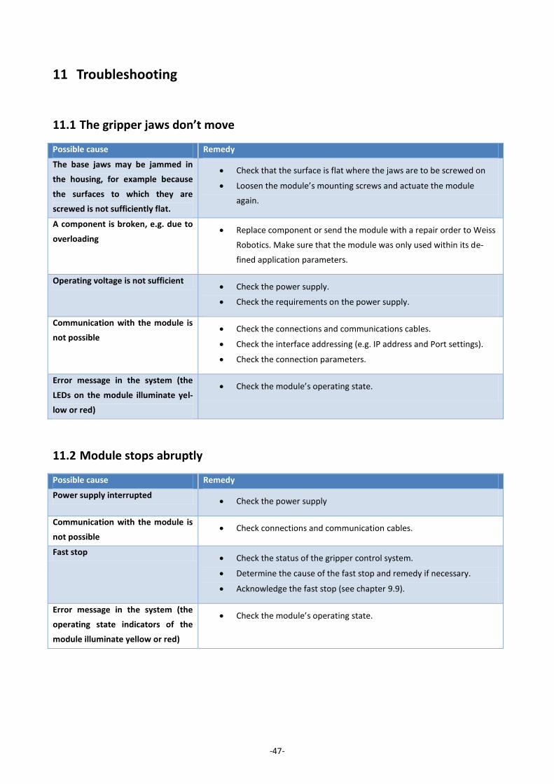
11 Troubleshooting
11.1 The gripper jaws don’t move
Possible cause Remedy
The base jaws may be jammed in
the housing, for example because
the surfaces to which they are
screwed is not sufficiently flat.
Check that the surface is flat where the jaws are to be screwed on
Loosen the module’s mounting screws and actuate the module
again.
A component is broken, e.g. due to
overloading Replace component or send the module with a repair order to Weiss
Robotics. Make sure that the module was only used within its de-
fined application parameters.
Operating voltage is not sufficient Check the power supply.
Check the requirements on the power supply.
Communication with the module is
not possible Check the connections and communications cables.
Check the interface addressing (e.g. IP address and Port settings).
Check the connection parameters.
Error message in the system (the
LEDs on the module illuminate yel-
low or red)
Check the module’s operating state.
11.2 Module stops abruptly
Possible cause Remedy
Power supply interrupted Check the power supply
Communication with the module is
not possible Check connections and communication cables.
Fast stop Check the status of the gripper control system.
Determine the cause of the fast stop and remedy if necessary.
Acknowledge the fast stop (see chapter 9.9).
Error message in the system (the
operating state indicators of the
module illuminate yellow or red)
Check the module’s operating state.

-48-
11.3 No connection to the web interface
Possible cause Remedy
Power supply interrupted Check the power supply.
Communication with the module is
not possible Check the connections and communications cable.
Check the network settings in the module.
Check the network settings in the computer.
-49-
12 EC Declaration of Incorporation
In terms of the EC Machinery Directive 2006/42/EG, Annex II, Part B
Manufacturer
Weiss Robotics GmbH & Co. KG
In der Gerste 2
D-71636 Ludwigsburg
Distributor Weiss Robotics GmbH & Co. KG
In der Gerste 2
D-71636 Ludwigsburg
We hereby declare that the following product:
Product designation: Electrical Parallel Gripper WSG 50
Type: WSG 50
Meets the applicable basic requirements of the Machinery Directive (2006/42/EC).
The incomplete machine may not be put into operation until conformity of the machine into which the
incomplete machine is to be installed with the provisions of the Machinery Directive (2006/42/EC) is
confirmed.
Applied harmonized standards, especially:
EN ISO 12100-1 Safety of machines – Basic concepts, general principles for design – Part 1:
Basic terminology, methodology
EN ISO 12100-2 Safety of machines – Basic concepts, general principles for design – Part 2:
Technical principles
The manufacturer agrees to forward on demand the special technical documents for the incomplete
machine to state offices.
The special technical documents according to Annex VII, Part B, belonging to the incomplete machine
have been created.
Person responsible for documentation: Dr.-Ing. Karsten Weiß, Tel.: +49(0)7141/642092-6
Location, Date/Signature: Ludwigsburg, September 2010
Details of the signatory: Weiss Robotics GmbH & Co. KG

© Weiss Robotics GmbH & Co. KG. All rights reserved. The technical data mentioned in this document can be changed to improve our products without prior notice. Used trademarks are the property of their respective trademark owners. Our products are not intended for use in life sup-port systems or systems whose failure can lead to personal injury.