bec apartment entry installation instructions and … apartment intercom install.pdf ·...
TRANSCRIPT
Application
The BEC Apartment Entry Intercoms provide two-way communications between the building entrance and each suite. Hands-free loudspeaker operation at the entrance/lobby panel and push button controlled communication at the suite/apartment locations provide for easy operation. Controlled door entry is permitted by push button operation at the suite in conjunction with electric door release.
Optional equipment is available to provide additional functionality, such as post office key door release, additional entrance panels, strobe light call indication and auxiliary relay for ancillary device operation (bells, lights, etc.).
Procedure
1. Read installation instructions to determine equipment location and installation methods.
2. Install housings (or back boxes) and wiring.3. Check wiring, connect and install equipment.4. Apply power and check operation.
Equipment Location
Suite/Apartment StationsLocate suite stations (also known as remote stations) where convenient for use. Install a housing or back box at the desired location.
Entrance/Lobby PanelUse the flush housing and trim frame for flush wall mounting. Locate the entrance panel where it is sheltered from weather.
Intercom AmplifierInstall the amplifier inside the entrance panel when using a flush mount housing. The amplifier must be installed outside the entrance panel when using a surface box and frame. Refer to Connections section, item #3, on page 2 for further details.
Wiring
Suite/Apartment StationsStations may be connected in risers using the following cable configurations:
3-wire stations: 1 twisted pair #22 AWG, plus 1 conductor #22 AWG per station in riser.
4-wire stations: 1 twisted pair #22 AWG, plus 1 conductor #22AWG, plus 1 conductor #22 AWG per station in riser.
5-wire stations: 1 twisted pair #22 AWG, plus 2 conductor #22 AWG, plus 1 conductor #22 AWG per station in riser.
The maximum cable length is 400 feet (120 meters). Additional risers may be added as needed. Station cables must not be run in the same conduit with (or too close to) electrical wiring or background music, and must not be close to fluorescent lighting or other electrical equipment. Failing to observe this requirement can result in noise entering the intercom audio. Ensure that sufficient amounts of cable are left in the back box to make connections to stations.
TransformerCable wiring must be 2 conductor #18 AWG with a maximum cable length of 80 feet (25 meters). If using #14 AWG wire, this distance can be extended to 200 feet (60 meters). Route cable away from suite station wiring and maintain a minimum of 3 feet (1 meter) of clearance between the transformer and the amplifier.
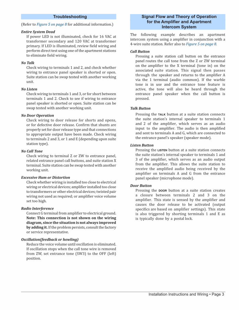
Door ReleaseCable wiring must be 2 conductor #18 AWG with a maximum length of 50 feet (15 meters). See Figure 2 on page 5 for specifics of each door control unit configuration. Note: An SS106 transformer must be used for 24 VAC doorstrike and 12 VDC Maglock applications (8 volt tap required).
BEC Apartment Entry Installation Instructions and Wiring
Apartment Entrance Panels • Rev. 6
BEC quality system is registered by UL® to the ISO 9001 standard. (Reference #10001510.)
BEC - Williamsville, NY 14221 Phone: (888) 556-3998 or (716) 689-0871
www.becaudio.com

Page 2 • Installation Instructions and Wiring
Connections
Before connecting to unit and applying power, verify that wires are free from shorts and grounds. Make connections as per Figure 1 on page 4. Observe the following notes:
1. Do not apply power to the transformer primary untilthe entire system has been installed and checked forshorts and grounds. The common wires connecting toterminals 1, 2, 3, E and 5 must show open circuit when tested with an ohmmeter.
2. Use twisted pair wiring as shown. Do not interchangewires or reverse polarity.
3. You may install intercom amplifier inside theentrance panel when using the flush housing. If it isnecessary to install the amplifier elsewhere due totemperature extremes (operating temperature rangeis 0–30°C) or because the entrance panel is not large enough to house the amplifier, then use a 2 conductorshielded cable for the entrance panel speaker(connect shield drain to amplifier terminal G).
4. The amplifier must be located at least 3 feet (1 meter)from the transformer or other electrical devices.
5. Do not run wiring for station common wires and entrancepanel speaker in the same cable and/or conduit. Thiswill cause feedback on the system.
6. Door release wiring should be run separate fromentrance panel speaker wiring.
Shunt and Dipswitch Settings
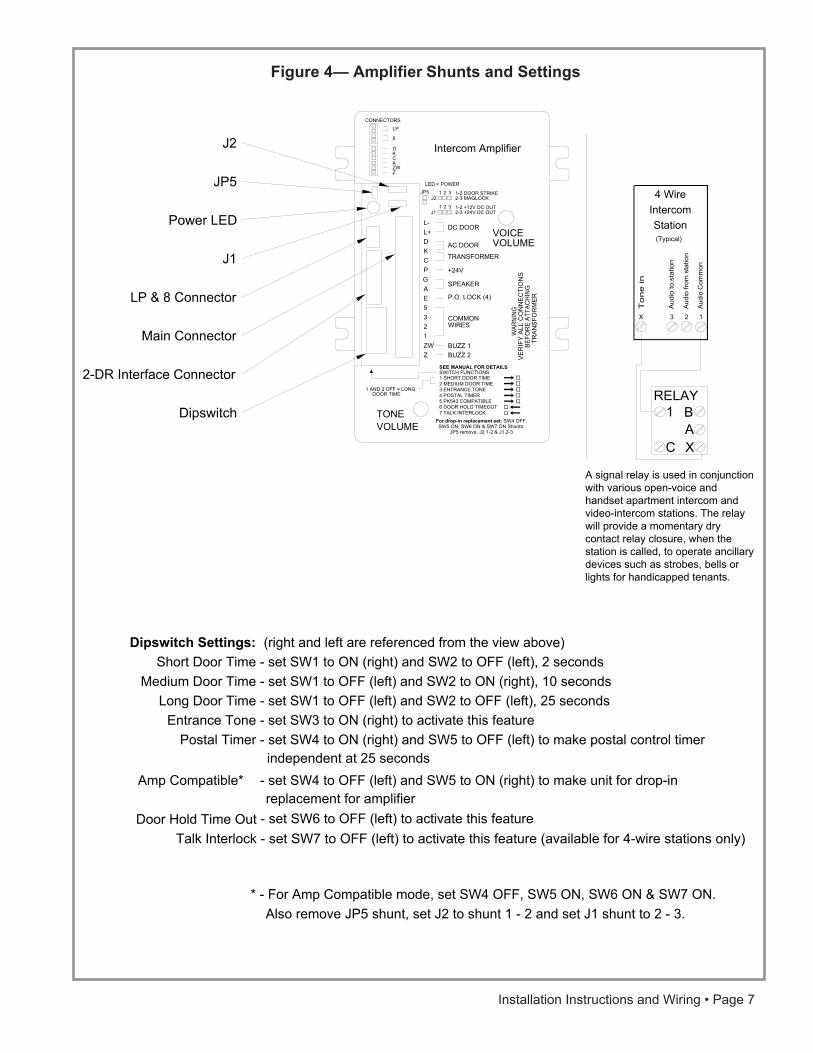
Set the dipswitches on the amplifier as per application requirements. See also Figure 4 on page 7. The select-able features and controls are as follows:
Shunt JP5 Install for maglock applications. Maximum current for maglock is 500 mA at 12 VDC, or 250 mA at 24 VDC.
Shunt J2 Place shunt across: 1–2 for doorstrike applications; 2–3 for maglock applications
Shunt J1 Place shunt across: 1–2 for +12 VDC maglock; 2–3 for +24 VDC maglock or AC/DC doorstrike applications
Short Door Time Set SW1 to ON (right) and SW2 to OFF (left), 2 seconds
Medium Door Time Set SW1 to OFF (left) and SW2 to ON (right), 10 seconds
Long Door Time Set SW1 to OFF (left) and SW2 to OFF (left), 25 seconds
Entrance Tone Set SW3 to ON (right) to activate this feature—must use warble tone
Postal Timer Set SW4 to ON (right) and SW5 to OFF (left) to make postal control timer independent at 25 seconds
Amp Compatible Set SW4 to OFF (left) and SW5 to ON (right) for PK543 drop-in replacement*
Door Hold Time Out Set SW6 to OFF (left) to activate this feature
Talk Interlock Set SW7 to OFF (left) to activate this feature (available for 4-wire stations only)
* For Amp Compatible mode, set SW4 OFF, SW5 ON, SW6 ON & SW7 ON. Also remove JP5 shunt, set J2 to shunt 1–2 and set J1 shunt to 2–3.
The Entrance Tone setting, when active, will generate a user feedback tone at the entrance panel when users press call buttons. If the warble tone is in use and the entrance tone feature is active, the tone will also be heard through the entrance panel speaker when the call button is pressed.
The Door Hold Time Out setting, when active, will allow the door control device (doorstrike, maglock, etc.) to time out normally, despite the door button being held at the suite.
Safety Tip: The Talk Interlock setting, when active, will require that the talk button (at the suite) is pressed before the door button will activate the door control device.
Optional Accessories
Install optional accessories according to the instructions provided.
Finish & Test Installation
1. Confirm that all equipment is properly installed.
2. Connect power to transformer primary (120 VAC), and ensure that local electrical codes have been compliedwith.
3. At the entrance panel, push each button and verify that the correct suite is called.
4. At each suite, push the talk and listen buttons to com-municate with a person at the entrance panel. Thenpush the door button to confirm that the door releaseoperates correctly.
Adjustments
Voice Volume and Tone Volume can be adjusted on the amplifier, via the access hole, with a small screwdriver.
Installation Instructions and Wiring • Page 3
Troubleshooting
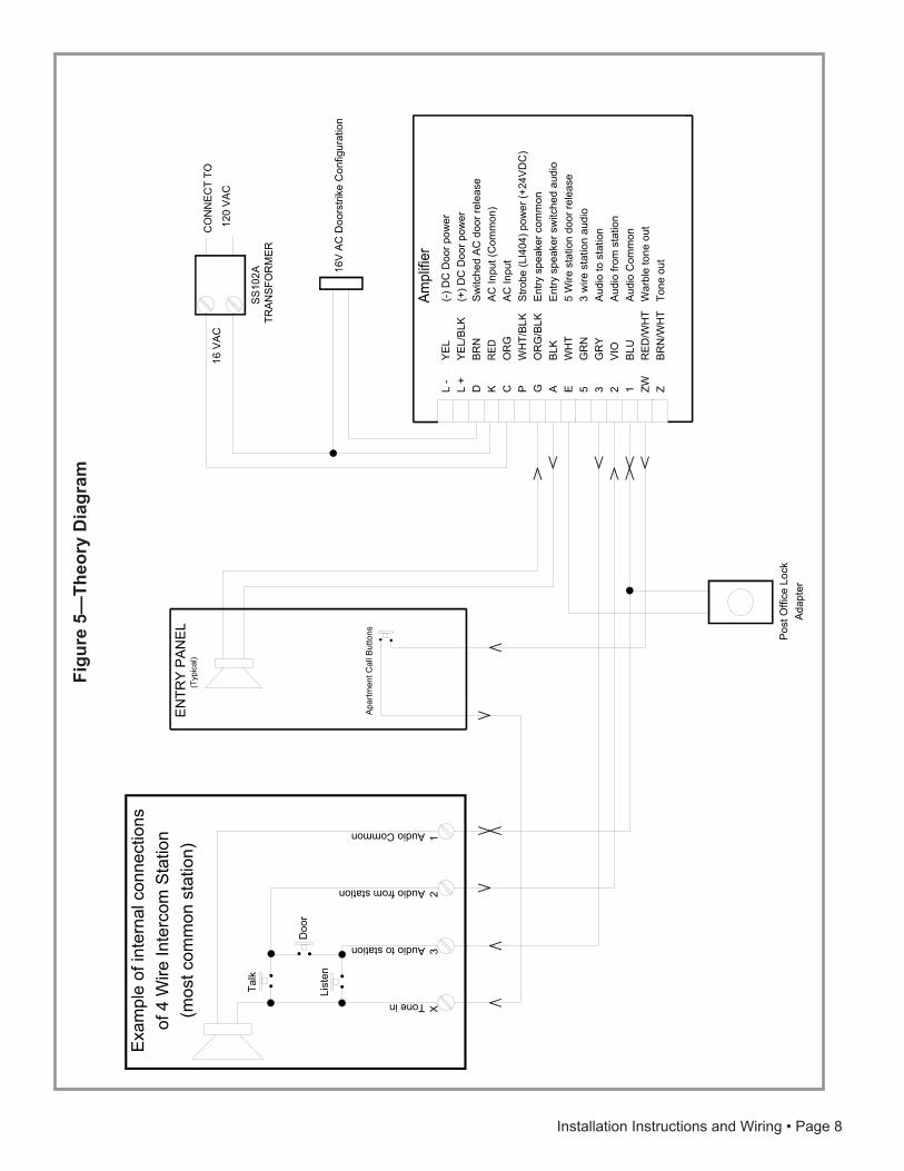
(Refer to Figure 5 on page 8 for additional information.)
Entire System DeadIf power LED is not illuminated, check for 16 VAC at transformer secondary and 120 VAC at transformer primary. If LED is illuminated, review field wiring and perform direct test using one of the apartment stations to eliminate field wiring.
No TalkCheck wiring to terminals 1 and 2, and check whether wiring to entrance panel speaker is shorted or open. Suite station can be swap tested with another working unit.
No ListenCheck wiring to terminals 1 and 3, or for short between terminals 1 and 2. Check to see if wiring to entrance panel speaker is shorted or open. Suite station can be swap tested with another working unit.
No Door OperationCheck wiring to door release for shorts and opens, or for defective door release. Confirm that shunts are properly set for door release type and that connections to appropriate output have been made. Check wiring to terminals 2 and 3, or 1 and E (depending upon suite station type).
No Call ToneCheck wiring to terminal Z or ZW to entrance panel, related entrance panel call buttons, and suite station X terminal. Suite station can be swap tested with another working unit.
Excessive Hum or DistortionCheck whether wiring is installed too close to electrical wiring or electrical devices; amplifier installed too close to transformers or other electrical devices; twisted pair wiring not used as required; or amplifier voice volume set too high.
Radio InterferenceConnect G terminal from amplifier to electrical ground. Note: This connection is not shown on the wiring diagram, since the situation is not always improved by adding it. If the problem persists, consult the factory or service representative.
Oscillation(feedback or howling)Reduce the voice volume until oscillation is eliminated. If oscillation stops when the call tone wire is removed from ZW, set entrance tone (SW3) to the OFF (left) position.
Signal Flow and Theory of Operation for the Amplifier and Apartment
Intercom System
The following example describes an apartment intercom system using a amplifier in conjunction with a 4-wire suite station. Refer also to Figure 5 on page 8.
Call ButtonPressing a suite station call button on the entrance panel routes the call tone from the Z or ZW terminal on the amplifier to the X terminal (tone in) on the associated suite station. This signal then passes through the speaker and returns to the amplifier A via the 1 terminal (audio common). If the warble tone is in use and the entrance tone feature is active, the tone will also be heard through the entrance panel speaker when the call button is pressed.
Talk ButtonPressing the talk button at a suite station connects the suite station’s internal speaker to terminals 1 and 2 of the amplifier, which serves as an audio input to the amplifier. The audio is then amplified and sent to terminals A and G, which are connected to the entrance panel’s speaker (speaker mode).
Listen ButtonPressing the listen button at a suite station connects the suite station’s internal speaker to terminals 1 and 3 of the amplifier, which serves as an audio output from the amplifier. This allows the suite station to receive the amplified audio being received by the amplifier on terminals A and G from the entrance panel speaker (microphone mode).
Door ButtonPressing the door button at a suite station creates a closure between terminals 2 and 3 on the amplifier. This state is sensed by the amplifier and causes the door release to be activated (output specifics are based on amplifier settings). This state is also triggered by shorting terminals 1 and E as is typically done by a postal lock.

Page 4 • Installation Instructions and Wiring
Figu
re 1
—Amplifier
Wiri
ng D
iagr
am
RED
OR
G
OR
G/B
LKB
LKW
HT
GR
NG
RY
VIO
BLU
RE
D/W
HT
BR
N/W
HT
A
mpl
ifier
WH
T/B
LK
BR
N
YE
L
K C G A E 5 3 2 1 ZW Z PDL +
L -
AC
Inpu
t (C
omm
on)
AC
Inpu
t
Ent
ry s
peak
er c
omm
onE
ntry
spe
aker
sw
itche
d au
dio
Aud
io to
sta
tion
Aud
io fr
om s
tatio
n
War
ble
tone
out
Tone
out
Sw
itche
d A
C d
oor r
elea
se
(+) D
C D
oor p
ower
(-) D
C D
oor p
ower
Aud
io C
omm
on
YE
L/B
LK
Stro
be (L
I404
) pow
er (+
24V
DC
)
5 W
ire s
tatio
n do
or re
leas
e3
wire
sta
tion
audi
o
ENTR
Y PA
NEL
(Typ
ical
)
Apar
tmen
t Cal
l But
tons
X3
21Audio Common
Audio from station
Audio to station(T
ypic
al)
4 W
ireIn
terc
omS
tatio
n
X5
1Audio Common
Switched Audio
Tone in(Typ
ical
)
3 W
ireIn
terc
omS
tatio
n
XE/
43
21Audio Common
Audio from station
Audio to station
5 Wire sta. door release(Typ
ical
)
5 W
ireIn
terc
omS
tatio
nTone in
Tone in
Pos
t Offi
ce L
ock
Ada
pter
CO
NN
ECT
TO 1
20 V
AC
SS
102A
TRAN
SFO
RM
ER
16 V
AC
If sh
ield
ed w
ire is
use
d, c
onne
ctsh
ield
s to
ora
nge/
blac
k w
ire (G
)at
am
plifi
er.
#18
AW
G W
ire
16V
AC
Doo
rstri
ke C
onfig
urat
ion
Rem
ove
shun
t on
JP5,
set
J1
shun
t to
2 an
d 3
and
J2 s
hunt
to 1
and
2. (
see
othe
r dia
gram
sfo
r add
ition
al c
onfig
urat
ions
)
Twis
ted
Pai
r
Twis
ted
Pai
rTw
iste
d P
air
Twis
ted
Pai
rN
otes
:1.
Use
#22
AW
G w
ire u
nles
s sh
own
othe
rwis
e.2.
War
ble
or S
tead
y To
ne is
har
d w
ire s
elec
tabl
e.3.
If en
try p
anel
has
han
dset
, con
nect
it in
pla
ce o
f spe
aker
.4.
3, 4
and
5 w
ire in
terc
om s
tatio
n ty
pes
may
be
used
in a
ny c
ombi
natio
n,
(Opt
iona
l)
5.D
oor r
elea
se w
iring
sho
uld
be ru
n se
para
te fr
om e
ntra
nce
pane
l spe
aker
wiri
ng.
6.S
hunt
s re
ferr
ed to
in d
iagr
ams
are
loca
ted
on amplifier
.
with
the
exce
ptio
n of
C d
evic
es.
See
not
e #4
7.Te
rmin
al P
is fo
r stro
be o
nly,
do
NO
T co
nnec
t oth
er w
ires
to th
is te
rmin
al.
DO N
OT
run
thes
e w
ires
in th
e sa
me
cabl
e! It
will
caus
e fe
edba
ck.
Wiri
ng fo
r 3, 4
and
5 W
ire In
terc
om S
tatio
ns
Installation Instructions and Wiring • Page 5
Figure 2—Doorstrike Applications
REDORG
ORG/BLKBLKWHTGRNGRYVIOBLURED/WHTBRN/WHT
Amplifier
WHT/BLK
BRN
YEL
KC
GAE5321ZWZ
P
DL + L -
AC Input (Common)AC Input
Entry speaker commonEntry speaker switched audio
Audio to stationAudio from station
Warble tone outTone out
Switched AC door release (+) DC Door power(-) DC Door power
Audio Common
YEL/BLK
Strobe (LI404) power (+24VDC)
5 Wire station door release3 wire station audio
CONNECT TO120 VAC
SS102ATRANSFORMER
16 VAC
#18 AWG Wire
16V DC Doorstrike Application:Remove JP5 ShuntSet J1 shunt to 2 and 3Set J2 shunt to 1 and 2
Doorstrike
REDORG
ORG/BLKBLKWHTGRNGRYVIOBLURED/WHTBRN/WHT
Amplifier
WHT/BLK
BRN
YEL
KC
GAE5321ZWZ
P
DL + L -
AC Input (Common)AC Input
Entry speaker commonEntry speaker switched audio
Audio to stationAudio from station
Warble tone outTone out
Switched AC door release (+) DC Door power(-) DC Door power
Audio Common
YEL/BLK
Strobe (LI404) power (+24VDC)
5 Wire station door release3 wire station audio
CONNECT TO120 VAC
SS106TRANSFORMER
#18 AWG Wire
+24V AC Doorstrike Application:Remove JP5 ShuntSet J1 shunt to 2 and 3Set J2 shunt to 1 and 2
Doorstrike
16 VAC Tap
8 VAC Tap
Common
#18 AWG Wire
#18 AWG Wire
IL82
6 PK
543A
Doo
rstri
ke A
pplic
atio
ns 2
Rev
2 10
2008
1
REDORG
ORG/BLKBLKWHTGRNGRYVIOBLURED/WHTBRN/WHT
Amplifier
WHT/BLK
BRN
YEL
KC
GAE5321ZWZ
P
DL + L -
AC Input (Common)AC Input
Entry speaker commonEntry speaker switched audio
Audio to stationAudio from station
Warble tone outTone out
Switched AC door release (+) DC Door power(-) DC Door power
Audio Common
YEL/BLK
Strobe (LI404) power (+24VDC)
5 Wire station door release3 wire station audio
CONNECT TO120 VAC
SS102ATRANSFORMER
16 VAC
#18 AWG Wire
+24VDC/250mA DC Maglock Application:Install JP5 ShuntSet J1 shunt to 2 and 3Set J2 shunt to 2 and 3
Maglock
REDORG
ORG/BLKBLKWHTGRNGRYVIOBLURED/WHTBRN/WHT
Amplifier
WHT/BLK
BRN
YEL
KC
GAE5321ZWZ
P
DL + L -
AC Input (Common)AC Input
Entry speaker commonEntry speaker switched audio
Audio to stationAudio from station
Warble tone outTone out
Switched AC door release (+) DC Door power(-) DC Door power
Audio Common
YEL/BLK
Strobe (LI404) power (+24VDC)
5 Wire station door release3 wire station audio
CONNECT TO120 VAC
SS106TRANSFORMER
#18 AWG Wire
+12VDC/500mA DC Maglock Application:Install JP5 ShuntSet J1 shunt to 1 and 2Set J2 shunt to 2 and 3
Maglock
16 VAC Tap
8 VAC Tap
Common
8
LP
4 pin header JP3,located in front ofmain connector.
#18 AWG Wire#18 AWG Wire
Note: LP and 8 are each available on twopins of the JP3 connector. Brackets areprovided to identify.
Page 6 • Installation Instructions and Wiring
Figu
re 3
— L
ED A
pplic
atio
ns
RED
OR
G
OR
G/B
LKB
LKW
HT
GR
NG
RY
VIO
BLU
RE
D/W
HT
BR
N/W
HT A
mpl
ifier
WH
T/B
LK
BR
N
YE
L
K C G A E 5 3 2 1 ZW ZPDL +
L -
AC
Inpu
t (C
omm
on)
AC
Inpu
t
Entry
spe
aker
com
mon
Ent
ry s
peak
er s
witc
hed
audi
o
Aud
io to
sta
tion
Aud
io fr
om s
tatio
n
War
ble
tone
out
Tone
out
Sw
itche
d A
C d
oor r
elea
se
(+) D
C D
oor p
ower
(-) D
C D
oor p
ower
Aud
io C
omm
on
YE
L/B
LK
Stro
be (L
I404
) pow
er (+
24VD
C)
5 W
ire s
tatio
n do
or re
leas
e3
wire
sta
tion
audi
o CO
NN
ECT
TO
120
VA
C
SS
102A
TRAN
SFO
RM
ER
16 V
AC
#18
AW
G W
ire
Pwr S
D -
F +
F FT1 T2
CO
NN
ECT
TO12
0 V
AC
SS
102A
TRAN
SFO
RM
ER
16 V
AC
8LP
4 pi
n he
ader
JP
3,lo
cate
d in
fron
t of
mai
n co
nnec
tor.
LED
pow
er fr
om Amplifier
(Max
20
stat
ions
)
X3
21Audio Common
Audio from station
Audio to station
4 W
ireIn
terc
omS
tatio
n
Tone in
LN LP
M
odel
F a
nd S
Sta
tions
LED
pow
er fr
om E
xter
nal S
ourc
e
X3
21Audio Common
Audio from station
Audio to station
4 W
ireIn
terc
omS
tatio
n
Tone in
LN LP
door
sw
itch
curre
nt
door
sw
itch
curre
nt
LED
Pow
er C
alcu
latio
ns fo
r Doo
r Sw
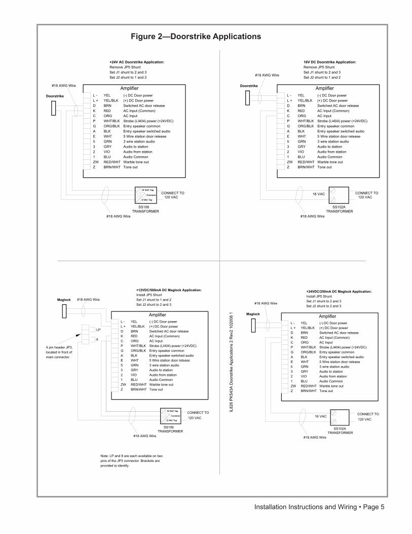
itch:
Eac
h ap
artm
ent s
tatio
n w
ith a
doo
r ind
icat
or L
ED
will
draw
17m
A
whe
n th
e do
or s
witc
h cl
oses
(cau
sed
by th
e ac
tual
bui
ldin
g do
or
bein
g op
ened
). Th
e am
plifi
er c
an s
uppl
y a
max
imum
of
20 a
partm
ent s
tatio
ns. I
f an
exte
rnal
pow
er s
uppl
y is
use
d th
en
the
over
all n
umbe
r of a
partm
ent s
tatio
ns c
an b
e m
ultip
lied
by
17m
A (m
illiam
ps) t
o de
term
ine
pow
er s
uppl
y lo
ad a
nd s
witc
h m
axim
um c
urre
nt ra
ting.
Not
e: L
P a
nd 8
are
eac
h av
aila
ble
on tw
opi
ns o
f the
JP
3 co
nnec
tor.
Bra
cket
s ar
epr
ovid
ed to
iden
tify.
M
odel
F a
nd S
Sta
tions
Installation Instructions and Wiring • Page 7
Figure 4— Amplifier Shunts and Settings
X 3 2 1
Aud
ioC
omm
on
Aud
io fr
om s
tatio
n
Aud
ioto
stat
ion
(Typical)
4 WireIntercomStation
To
ne
in
1
C
BAX
RELAY
VOICEVOLUME
TONEVOLUME
WAR
NING
SWITCH FUNCTIONSSEE MANUAL FOR DETAILS
1 SHORT DOOR TIME2 MEDIUM DOOR TIME3 ENTRANCE TONE4 POSTAL TIMER5 PK543 COMPATIBLE6 DOOR HOLD TIMEOUT7 TALK INTERLOCK
L-L+DKC
GAE5321ZWZ
DC DOOR
AC DOOR
TRANSFORMER
SPEAKER
P.O. LOCK (4)
COMMONWIRES
BUZZ 1BUZZ 2
LED = POWER
LP
8
DKCAZWZ
P +24V
CONNECTORS
1 AND 2 OFF = LONG DOOR TIME
For drop-in replacement set: SW4 OFF, SW5 ON, SW6 ON & SW7 ON Shunts:
JP5 remove, J2 1-2 & J1 2-3
J1
1 2 3
21 3
1-2 DOOR STRIKE2-3 MAGLOCK
1-2 +12V DC OUT2-3 +24V DC OUT
JP5J2
J2
JP5
Power LED
J1
LP & 8 Connector
Main Connector
2-DR Interface Connector
Dipswitch
T
RAN
SFO
RM
ER
BEFO
RE
ATTA
CH
ING
VE
RIF
Y A
LL C
ON
NE
CTI
ON
S
Dipswitch Settings:
Medium Door TimeLong Door Time
Entrance TonePostal Timer
Short Door Time - set SW1 to ON (right) and SW2 to OFF (left), 2 seconds - set SW1 to OFF (left) and SW2 to ON (right), 10 seconds - set SW1 to OFF (left) and SW2 to OFF (left), 25 seconds - set SW3 to ON (right) to activate this feature
(right and left are referenced from the view above)
- set SW4 to ON (right) and SW5 to OFF (left) to make postal control timer independent at 25 seconds
Door Hold Time OutTalk Interlock
Amp Compatible* - set SW4 to OFF (left) and SW5 to ON (right) to make unit for drop-in
* - For Amp Compatible mode, set SW4 OFF, SW5 ON, SW6 ON & SW7 ON. Also remove JP5 shunt, set J2 to shunt 1 - 2 and set J1 shunt to 2 - 3.
replacement for amplifier- set SW6 to OFF (left) to activate this feature- set SW7 to OFF (left) to activate this feature (available for 4-wire stations only)
Intercom Amplifier
A signal relay is used in conjunction with various open-voice and handset apartment intercom and video-intercom stations. The relay will provide a momentary dry contact relay closure, when the station is called, to operate ancillary devices such as strobes, bells or lights for handicapped tenants.
Figu
re 5
—Th
eory
Dia
gram
RED
OR
G
OR
G/B
LKB
LKW
HT
GR
NG
RY
VIO
BLU
RE
D/W
HT
BR
N/W
HT
Ampl
ifier
WH
T/B
LK
BR
N
YE
L
K C G A E 5 3 2 1 ZW ZPDL +
L -
AC
Inpu
t (C
omm
on)
AC
Inpu
t
Ent
ry s
peak
er c
omm
onE
ntry
spe
aker
sw
itche
d au
dio
Aud
io to
sta
tion
Aud
io fr
om s
tatio
n
War
ble
tone
out
Tone
out
Sw
itche
d A
C d
oor r
elea
se
(+) D
C D
oor p
ower
(-) D
C D
oor p
ower
Aud
io C
omm
on
YE
L/B
LK
Stro
be (L
I404
) pow
er (+
24V
DC
)
5 W
ire s
tatio
n do
or re
leas
e3
wire
sta
tion
audi
o
ENTR
Y PA
NEL
(Typ
ical
)
Apa
rtmen
t Cal
l But
tons Pos
t Offi
ce L
ock
Ada
pter
CO
NN
ECT
TO
120
VAC
SS10
2ATR
ANSF
OR
MER
16 V
AC
16V
AC
Doo
rstri
ke C
onfig
urat
ion
Audio Common
Audio from station
Audio to station
Talk
List
en
Doo
r
Exa
mpl
e of
inte
rnal
con
nect
ions
of 4
Wire
Inte
rcom
Sta
tion
(mos
t com
mon
sta
tion)
Tone in
X3
21
Installation Instructions and Wiring • Page 8

Installation for Multi DoorsDual Entrance Control Unit
ApplicationThe 2-DR Dual Entrance Control Unit provides a means to connect BEC Apartment Intercom amplifiers to more than one entrance. Voice and door release functions are automatically transferred to the calling entrance. The quantity of 2-DRs needed is equal to one less than the number of entrances.
ProcedureWarning: This switching unit will not function unless programmed for use—see Test Step #1.
1. Determine equipment location.2. Install wiring.3. Install equipment.4. Check wiring and make connections.5. Apply power and check operation.
Equipment LocationLocate the 2-DR within 3' (1 m) of the intercom amplifier. If more than one 2-DR is used, install them all in the same area. Keep the 2-DR away from direct heat or extreme cold. Operating temperature should be between 10°F and 90°F.
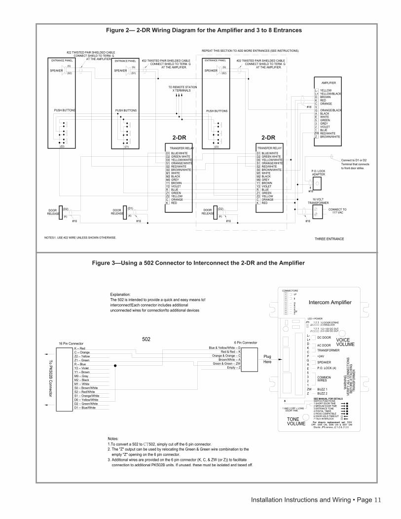
Wiring1. The first 2-DR will support two entrances; each addi-
tional 2-DR will support one additional entrance. Forexample, a three-entrance system will have two 2-DRs.See Figure 2 for an example with additional entrances.
2. Wire the suite station common wires to the amplifier, andwire the power transformer according to instructions sup-plied with the amplifier.
3. If more than one 2-DR is used, run 1 cond. #18 plus 7cond. #22 between 2-DRs. Run 3 cond. #18 plus 3 cond.#22 from the last 2-DR to the amplifier.
4. Run 2 cond. #22 twisted shielded (2 cond. #22, plus 2cond. #22 shielded for 205 amplifiers) from eachentrance panel to the associated 2-DR.
5. Run multi-cond. #22 cable (use 1 cond. per suitestation) from entrance panel to entrance panel, and fromone entrance panel to the suite stations, as required byinstructions supplied with amplifier.
6. From each entrance door release, run 1 cond. #18 to the2-DR and 1 cond. #18 to the amplifier.
7. If a Post Office (P.O.) lock adapter is used, run 1 cond. #18to the amplifier, and 1 cond. #18 to the associated doorrelease from the P.O. lock adapter. In the wiring diagram,the P.O. lock adapter is shown connected to door release#1, but it may be connected to whichever door release isrequired.
Connections1. Make connections as shown on the wiring diagram for
the amplifier being used. (For the intercom amplifier,refer to Figure 1, Figure 2 and Figure 3. If more than two2-DRs are used, break the connections going from the 2-DRs outside the dashed lines to the amplifier and insertthe wiring shown inside the dashed lines for anyadditional 2-DRs.
2. If a P.O. lock adapter is used, do not connect it until a P.O.lock is obtained from the post office. When ready, makeconnections as shown on the appropriate wiring diagram.
3. Connect transformer to power source and follow the testprocedures in the next section.
TestAfter performing the test required in the amplifier’s instructions, do the following:
1. The 2-DR must be programmed to operate with theamplifier being used. Locate the programming switch andset switches as follows.
To use the intercom amplifier, set switches 2 and 4 onand switches 1, 3 and 5 off. Failure to set theprogramming switches properly will result in faultyoperation, but will not cause permanent damage to the 2-DR.
2. Perform tests required in the amplifier’s instructions, thenat each entrance, press a call button and observe the fol-lowing:
a. The buzz tone should be heard at the called suite station.
b. If the Entrance Tone is enabled at the amplifier, thenthe buzz tone should be heard at the entrance panel.
Installation Instructions and Wiring • Page 9
L-L+DKCVGAE
2
YELLOWYELLOW/BLACKBROWNREDORANGE
ORANGE/BLACKBLACKWHITEGREENGREYVIOLETBLUERED/WHITEBROWN/WHITE
AMPLIFIER
!!!!!!!TRANSFER RELAY
YELLOW / WHITE
BLUE / WHITEGREEN / WHITE
ORANGE / WHITERED / WHITEBROWN / WHITEWHITEBLACKGREYBROWNVIOLETBLUEGREENYELLOWORANGERED
D2D1
D0S1S2S0M1M2M0Y1Y2RZ1Z2CK
ENTRANCE PANEL ENTRANCE PANEL
SPEAKER SPEAKER
PUSHBUTTONS PUSHBUTTONS
DOORRELEASE
#22 TWISTED PAIR SHIELDED CABLE #22 TWISTED PAIR SHIELDED CABLECONNECT SHIELD TO TERM G AT CONNECT SHIELD TO TERM G AT THE AMPLIFIER. THE AMPLIFIER.
16 VOLTTRANSFORMER
#18
#18
#18
#18
#18
NOTES:1. USE #22 WIRE UNLESS SHOWN OTHERWISE.
CONNECT TO117 VAC
TOREMOTESTATION
XTERMINALS
TWO ENTRANCE
(D2)
DOORRELEASE
(D1)
P.O.LOCKADAPTER
(Z2)
(S2)
(G)
(S1)
(G)
(Z1)
(K)
(K)
35
1ZWZ
c. Voice communication should be possible with the calledsuite station.
d. If the door button is pressed at the suite station, the doorrelease should operate. When the door release timehas passed, the 2-DR’s red test light should be off.
3. If the P.O. lock adapter is installed, it may be tested by usinga postal service key, or by operating the P.O. lock adaptermicro switch if a key is unavailable. The door time delayon the amplifier does not affect the P.O. lock adapter.
TroubleshootingIf the system fails to operate properly, check all wiring. If the wiring is correct, check the troubleshooting points on the amplifier installation instructions. Then check the following:
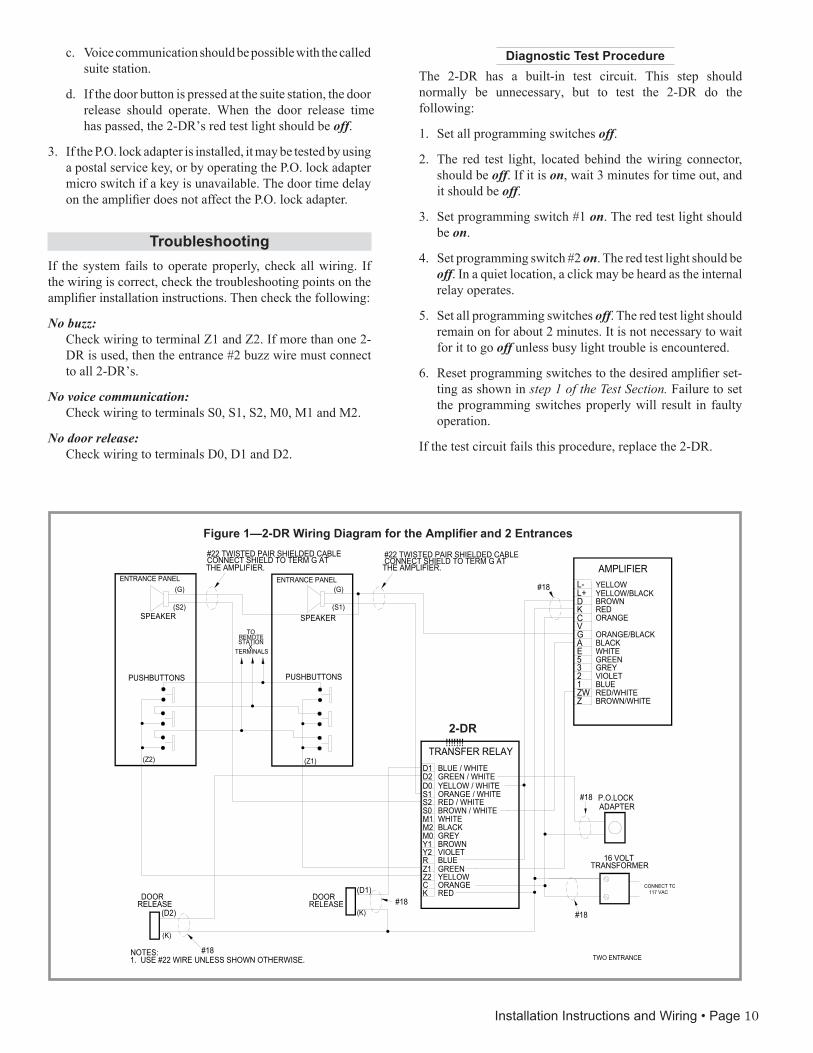
No buzz:Check wiring to terminal Z1 and Z2. If more than one 2-DR is used, then the entrance #2 buzz wire must connect to all 2-DR’s.
No voice communication:Check wiring to terminals S0, S1, S2, M0, M1 and M2.
No door release:Check wiring to terminals D0, D1 and D2.
Diagnostic Test ProcedureThe 2-DR has a built-in test circuit. This step should normally be unnecessary, but to test the 2-DR do the following:
1. Set all programming switches off.
2. The red test light, located behind the wiring connector,should be off. If it is on, wait 3 minutes for time out, andit should be off.
3. Set programming switch #1 on. The red test light shouldbe on.
4. Set programming switch #2 on. The red test light should beoff. In a quiet location, a click may be heard as the internalrelay operates.
5. Set all programming switches off. The red test light shouldremain on for about 2 minutes. It is not necessary to waitfor it to go off unless busy light trouble is encountered.
6. Reset programming switches to the desired amplifier set-ting as shown in step 1 of the Test Section. Failure to setthe programming switches properly will result in faultyoperation.
If the test circuit fails this procedure, replace the 2-DR.
Figure 1—2-DR Wiring Diagram for the Amplifier and 2 Entrances
2-DR
Installation Instructions and Wiring • Page 10
SPEAKER
CVG
L-L+
KD
21ZWZ
EA
35
YELLOW/BLACK
AMPLIFIER
REDORANGE
YELLOW
BROWN
RED/WHITEBROWN/WHITE
ORANGE/BLACK
VIOLETGREY
BLUE
GREEN
BLACKWHITE
S0M1M2
D2D1
S2S1D0
Z2Z1
KC
Y2Y1M0
R
ORANGE/WHITE
TRANSFER RELAY
YELLOW/WHITE
RED/WHITEBROWN/WHITE
BLUE/WHITEGREEN WHITE
ORANGE
BLACK
YELLOW
VIOLET
GREEN
RED
BROWN
BLUE
WHITE
GREY
#18
SPEAKER
PUSH BUTTONS
SPEAKER
S0M1M2
D2D1
S2S1D0
Z2Z1
KC
Y2Y1M0
R
ORANGE/WHITE
TRANSFER RELAY
YELLOW/WHITE
RED/WHITEBROWN/WHITE
BLUE/WHITEGREEN WHITE
ORANGE
BLACK
YELLOW
VIOLET
GREEN
RED
BROWN
BLUE
WHITE
GREY
#18 #18#18 #18
#18
#22 TWISTED PAIR SHIELDED CABLECONNECT SHIELD TO TERM. G
REPEAT THIS SECTION TO ADD MORE ENTRANCES (SEE INSTRUCTIONS).
AT THE AMPLIFIER.
AT THE AMPLIFIER.
#22 TWISTED PAIR SHIELDED CABLECONNECT SHIELD TO TERM. G
CONNECT SHIELD TO TERM. G#22 TWISTED PAIR SHIELDED CABLE
AT THE AMPLIFIER.
X TERMINALSTO REMOTE STATION
RELEASE 117 VAC
TRANSFORMER16 VOLT
CONNECT TO
1. USE #22 WIRE UNLESS SHOWN OTHERWISE.NOTES:
RELEASE RELEASEDOOR DOORDOOR
PUSH BUTTONSPUSH BUTTONS
THREE ENTRANCE
ENTRANCE PANEL ENTRANCE PANEL ENTRANCE PANEL
(D1) (D2)
P.O. LOCKADAPTER
Connect to D1 or D2Terminal that connectsto front door strike.
(G) (G) (G)
(S2)(S2) (S1)
(Z2) (Z1) (Z2)
(K)(K)
(D2)
(K)
VOICE VOLUME
TONEVOLUME
WAR
NING
VERI
FY A
LL C
ONN
ECTI
ONS
BEF
ORE
ATT
ACHI
NG T
RANS
FORM
ER
SWITCH FUNCTIONSSEE MANUAL FOR DETAILS
1 SHORT DOOR TIME2 MEDIUM DOOR TIME3 ENTRANCE TONE4 POSTAL TIMER5 PK543 COMPATIBLE6 DOOR HOLD TIMEOUT7 TALK INTERLOCK
L-L+DKC
GAE5321ZWZ
DC DOOR
AC DOORTRANSFORMER
SPEAKER
P.O. LOCK (4)
COMMONWIRES
BUZZ 1BUZZ 2
LED = POWER
LP
8
DKCAZWZ
P +24V
CONNECTORS
1 AND 2 OFF = LONG DOOR TIME
For drop-in replacement set: SW4 OFF, SW5 ON, SW6 ON & SW7 ON!
Shunts: JP5 remove, J2 1-2 & J1 2-3
J1
1 2 3
21 3
1-2 DOOR STRIKE2-3 MAGLOCK1-2 +12V DC OUT2-3 +24V DC OUT
JP5J2
Blue & Yellow/White -- DK -- RedC -- OrangeZ2 -- YellowZ1 -- GreenR -- BlueY2 -- VioletY1 -- BrownM0 -- GrayM2 -- BlackM1 -- WhiteS0 -- Brown/WhiteS2 -- Red/WhiteS1 -- Orange/WhiteD0 -- Yellow/WhiteD2 -- Green/WhiteD1 -- Blue/White
Red & Red -- KOrange & Orange -- C
Brown/White -- AGreen & Green -- ZW
Empty -- Z
16 Pin Connector 6 Pin Connector
Explanation:The 502 is intended to provide a quick and easy means to!interconnect!Each connector includes additional unconnected wires for connection!to additional devices
Notes:1. To convert a 502 to CT502, simply cut off the 6 pin connector.2. The "Z" output can be used by relocating the Green & Green wire combination to the
empty "Z" opening on the 6 pin connector.3. Additional wires are provided on the 6 pin connector (K, C, & ZW (or Z)) to facilitate
connection to additional PK502B units. If unused, these must be isolated and taped off.
502
PlugHere
To PK502B Connector
Figure 2— 2-DR Wiring Diagram for the Amplifier and 3 to 8 Entrances
Figure 3—Using a 502 Connector to Interconnect the 2-DR and the Amplifier
2-DR 2-DR
Intercom Amplifier
Installation Instructions and Wiring • Page 11