beach topography surveying using unmanned aerial vehicle
TRANSCRIPT

Volume 29 Issue 1 Article 1
Beach Topography Surveying Using Unmanned Aerial Vehicle Beach Topography Surveying Using Unmanned Aerial Vehicle Photogrammetry Technology Photogrammetry Technology
Hui-Ming Fang Bachelor Degree Program in Ocean Engineering and Technology, National Taiwan Ocean University, Taiwan
Kuan-Tsung Chang Department of Civil Engineering and Environmental Informatics, Minghsin University of Science and Technology, Taiwan
Sung-Shan Hsiao Department of Harbor and River Engineering, National Taiwan Ocean University, Center of Excellence for Ocean Engineering, Taiwan, [email protected]
Shih-Peng Chiang Department of Harbor and River Engineering, National Taiwan Ocean University, Taiwan
Follow this and additional works at: https://jmstt.ntou.edu.tw/journal
Part of the Fresh Water Studies Commons, Marine Biology Commons, Ocean Engineering Commons, Oceanography Commons, and the Other Oceanography and Atmospheric Sciences and Meteorology Commons
Recommended Citation Recommended Citation Fang, Hui-Ming; Chang, Kuan-Tsung; Hsiao, Sung-Shan; and Chiang, Shih-Peng (2021) "Beach Topography Surveying Using Unmanned Aerial Vehicle Photogrammetry Technology," Journal of Marine Science and Technology: Vol. 29 : Iss. 1 , Article 1. DOI: 10.51400/2709-6998.1000 Available at: https://jmstt.ntou.edu.tw/journal/vol29/iss1/1
This Research Article is brought to you for free and open access by Journal of Marine Science and Technology. It has been accepted for inclusion in Journal of Marine Science and Technology by an authorized editor of Journal of Marine Science and Technology.

RESEARCH ARTICLE
Beach Topography Surveying Using UnmannedAerial Vehicle Photogrammetry Technology
Hui-Ming Fang a, Kuan-Tsung Chang b, Sung-Shan Hsiao c,*, Shih-Peng Chiang d
a Bachelor Degree Program in Ocean Engineering and Technology, National Taiwan Ocean University, Taiwanb Department of Civil Engineering and Environmental Informatics, Minghsin University of Science and Technology, Taiwanc Department of Harbor and River Engineering, National Taiwan Ocean University, Center of Excellence for Ocean Engineering, Taiwand Department of Harbor and River Engineering, National Taiwan Ocean University, Taiwan
Abstract
The mechanisms of in situ topography changes must be identified for spatial planning in coastal areas. In this study,the authors used in situ direct measurement methods and indirect remote-sensing technologies to develop a method forbeach topography surveillance. Unmanned aerial vehicles (UAVs) have advantages of high portability and mobility andlow operating altitude. Therefore, a UAV was equipped with a lightweight camera and a positioning system thatcomprised a global positioning system and an inertial measurement unit. Aerial photogrammetry and aerial triangu-lation methods were adopted for matching image feature points to obtain the corresponding topographic points in thesand. A virtual base station with real-time kinematic positioning functionality was used to measure the coordinates ofthe ground control points for correcting the actual coordinates to obtain actual topographic points of the beach sand. Theresults obtained using image-matching point clouds and direct measurements were compared. The ground sampledistance of a UAV at the operational altitude of 70 m was 3.26 cm. Moreover, the average elevation error was 3.20 cm, andthe root mean square error was 0.169 m. The measurement error was ±25 cm, which was within the acceptance criteria of±50 cm set by Water Resources Agency, Ministry of Economic Affairs, Taiwan. UAV imaging technology can increasethe efficiency of conventional manual sampling and reduce the cost of indirect observations, thus minimizing themeasurement errors and field measurement costs.
Keywords: Unmanned aerial vehicles, Photogrammetry, Beach topography
1. Introduction
T aiwan is surrounded by oceans. Conductinganthropogenic development either for
coastal development or marine protection willeventually create problems related to coastalconservation. The increasing volume of discus-sions on global climate change has graduallyattracted public attention toward coastal conser-vation. Thus, one should be able to adequatelycomprehend the mechanism of changes in coastaltopography changes to implement coastal con-servation. Topographic survey methods used for
monitoring topographic changes can be catego-rized into direct and indirect methods, namely insitu observation and remote-sensing methods,respectively. Specifically, most in situ observa-tions to monitor the changes in the topography ofa region are conducted using conventional topo-graphic mapping techniques and auxiliarymethods, such as Global Navigation SatelliteSystem receivers or a Total Station (TS). In remotesensing, data related to objects, regions, or phe-nomena can be obtained without physical contactwith the measured target. Short-term periodicsurveys conducted during conventional beach
Received 11 March 2020; revised 7 April 2020; accepted 19 May 2020.Available online 31 March 2021
* Corresponding author. Fax: þ886 2 24629557.E-mail address: [email protected] (S.-S. Hsiao).
https://doi.org/10.51400/2709-6998.10002709-6998/© 2021 National Taiwan Ocean University.
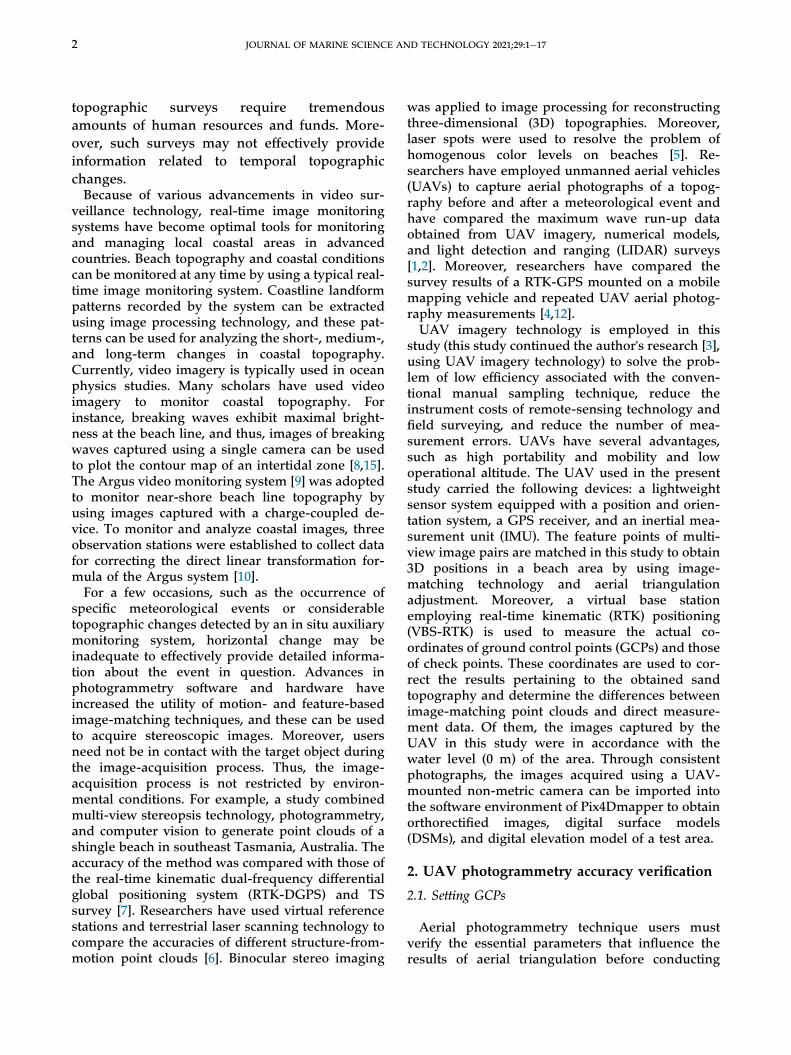
topographic surveys require tremendousamounts of human resources and funds. More-over, such surveys may not effectively provideinformation related to temporal topographicchanges.Because of various advancements in video sur-
veillance technology, real-time image monitoringsystems have become optimal tools for monitoringand managing local coastal areas in advancedcountries. Beach topography and coastal conditionscan be monitored at any time by using a typical real-time image monitoring system. Coastline landformpatterns recorded by the system can be extractedusing image processing technology, and these pat-terns can be used for analyzing the short-, medium-,and long-term changes in coastal topography.Currently, video imagery is typically used in oceanphysics studies. Many scholars have used videoimagery to monitor coastal topography. Forinstance, breaking waves exhibit maximal bright-ness at the beach line, and thus, images of breakingwaves captured using a single camera can be usedto plot the contour map of an intertidal zone [8,15].The Argus video monitoring system [9] was adoptedto monitor near-shore beach line topography byusing images captured with a charge-coupled de-vice. To monitor and analyze coastal images, threeobservation stations were established to collect datafor correcting the direct linear transformation for-mula of the Argus system [10].For a few occasions, such as the occurrence of
specific meteorological events or considerabletopographic changes detected by an in situ auxiliarymonitoring system, horizontal change may beinadequate to effectively provide detailed informa-tion about the event in question. Advances inphotogrammetry software and hardware haveincreased the utility of motion- and feature-basedimage-matching techniques, and these can be usedto acquire stereoscopic images. Moreover, usersneed not be in contact with the target object duringthe image-acquisition process. Thus, the image-acquisition process is not restricted by environ-mental conditions. For example, a study combinedmulti-view stereopsis technology, photogrammetry,and computer vision to generate point clouds of ashingle beach in southeast Tasmania, Australia. Theaccuracy of the method was compared with those ofthe real-time kinematic dual-frequency differentialglobal positioning system (RTK-DGPS) and TSsurvey [7]. Researchers have used virtual referencestations and terrestrial laser scanning technology tocompare the accuracies of different structure-from-motion point clouds [6]. Binocular stereo imaging
was applied to image processing for reconstructingthree-dimensional (3D) topographies. Moreover,laser spots were used to resolve the problem ofhomogenous color levels on beaches [5]. Re-searchers have employed unmanned aerial vehicles(UAVs) to capture aerial photographs of a topog-raphy before and after a meteorological event andhave compared the maximum wave run-up dataobtained from UAV imagery, numerical models,and light detection and ranging (LIDAR) surveys[1,2]. Moreover, researchers have compared thesurvey results of a RTK-GPS mounted on a mobilemapping vehicle and repeated UAV aerial photog-raphy measurements [4,12].UAV imagery technology is employed in this
study (this study continued the author's research [3],using UAV imagery technology) to solve the prob-lem of low efficiency associated with the conven-tional manual sampling technique, reduce theinstrument costs of remote-sensing technology andfield surveying, and reduce the number of mea-surement errors. UAVs have several advantages,such as high portability and mobility and lowoperational altitude. The UAV used in the presentstudy carried the following devices: a lightweightsensor system equipped with a position and orien-tation system, a GPS receiver, and an inertial mea-surement unit (IMU). The feature points of multi-view image pairs are matched in this study to obtain3D positions in a beach area by using image-matching technology and aerial triangulationadjustment. Moreover, a virtual base stationemploying real-time kinematic (RTK) positioning(VBS-RTK) is used to measure the actual co-ordinates of ground control points (GCPs) and thoseof check points. These coordinates are used to cor-rect the results pertaining to the obtained sandtopography and determine the differences betweenimage-matching point clouds and direct measure-ment data. Of them, the images captured by theUAV in this study were in accordance with thewater level (0 m) of the area. Through consistentphotographs, the images acquired using a UAV-mounted non-metric camera can be imported intothe software environment of Pix4Dmapper to obtainorthorectified images, digital surface models(DSMs), and digital elevation model of a test area.
2. UAV photogrammetry accuracy verification
2.1. Setting GCPs
Aerial photogrammetry technique users mustverify the essential parameters that influence theresults of aerial triangulation before conducting
2 JOURNAL OF MARINE SCIENCE AND TECHNOLOGY 2021;29:1e17

UAV aerial photography to obtain accurate topo-graphic data. These parameters, such as accuracy,form, GCP distribution, interior orientation, andcamera imperfections, substantially influence theposition correction of image points. Parameters,such as planar and vertical control measurement,GCP forms, and GCP distribution, should be plan-ned according to the actual beach topographybefore conducting UAV imaging for beach topog-raphy mapping. The GCP distribution should meetthe adjustment requirements of aerial triangulation.Specifically, the aerial photographs covering theGCPs of an area can be used to improve thecomputational reliability and accuracy of aerialtriangulation adjustment [11]. To verify the accuracyof UAV surveys of beach topography, a flat and non-obstacle beach volleyball court in the NationalTaiwan Ocean University campus was selected asthe test area. Three control points numbered T29,T30, and T31 built by the 10th River ManagementOffice, Water Resources Agency, surrounding thetest area can be used as reference points, shown asFig. 1. In Fig. 1, the test area is denoted by therectangular area marked with red lines. To verifythe reliability of the given coordinates of the threereference points, a VBS-RTK positioning methodwas used to measure and calibrate the control sys-tem for UAV topographic surveying. Table 1 lists thecoordinates measured using the VBS-RTK methodand those of the three reference points. The distanceresidual between the baselines consisting of tworeference points reached 0.5e2.0 cm, and the
orientation residual between vector orientationscalculated using the given coordinates and thosemeasured using the VBS-RTK method was smallerthan 500, as summarized in Table 2. Thus, the vali-dation results indicated that the aforementionedthree reference points can be used to measure thecoordinates of the GCPs and obtain a referencetopographic result. Because GPS-assisted aerialtriangulation can be performed during UAVsurveying, only four artificial marks distributed inthe corners of the test area and T30 were used as theGCPs in the subsequent UAV flights (see Fig. 2). Theaverage differences between the given and corre-sponding measured coordinates of the referencepoints can be regarded as systematic offsets to cor-rect the VBS-RTK-measured coordinates of the
Fig. 1. Reference control points in experimental area.
Fig. 2. Distribution of GCPs in beach court area.
Table 1. VBS-RTK-measured coordinates of reference points
Control point # Given coordinates Measured coordinates
N E Z N E Z
T29 2782788.768 328606.762 7.674 2782788.528 328607.338 10.015T30 2782763.035 328810.436 7.608 2782762.792 328811.026 9.970T31 2782653.960 328962.835 7.651 2782653.718 328963.432 10.029
JOURNAL OF MARINE SCIENCE AND TECHNOLOGY 2021;29:1e17 3

GCPs in a small test area. The results of this studysuggest that when using the VBS-RTK to performcontrol measurements in UAV surveying, at leastthree satellite control points and one first-orderbenchmark should be used as references for coor-dinate transformation.
2.2. Flight planning
To meet the requirements of direct geo-refer-encing, aerial photography was conducted with avideo camera drone (DJI Phantom 3 pro) equippedwith a GPS module and an IMU. However, the ac-curacy of the GPS module and IMU was inadequate.Therefore, GPS-assisted aerial triangulation wasemployed [16]. Aerial photogrammetry is moresuitable for a rectangular and open survey area.However, beach topography is a narrow terrain.Moreover, finding feature points for image match-ing is relatively difficult in a homogeneously sandyarea [5,13]. Imagery overlap was arranged using thesettings of the end lap (also called front overlap) andthe side lap (Fig. 3). The mathematical relationshipamong the parameters of the end and side laps canbe determined using Equations (1) and (2), respec-tively. The imagery front overlap ratio (left and rightimages) should be higher than 60% according to themapping standard [14]. The accuracy of topographic
map is a function of the ground sample distance(GSD) and the operational altitude (also called flyheight above ground level (AGL)). The proportionalrelationship between the AGL and the GSD can bederived using Equation (3) as a function of the res-olution of the photosensitive element. The GSDshould not be longer than 10 cm according to themapping standard for 1/1000 topographic maps. Thedouble-S-type flying course was adopted in thisstudy to increase the success rate of image matching(Fig. 4). Although this caused some disadvantages,such as long flight time, numerous images wereobtained from different angles. The courseincreased the overall overlap rate effectively tocover the measurement area and increased theobservation redundancy [17]. All the flight param-eters were set using the Pix4Dcapture application.
PE¼�G� BG
�� 100% ð1Þ
PS¼�G�W
G
�� 100% ð2Þ
where PE represents the end lap rate, PS the side laprate, G the length covered by a single photo, B theflying base length, and W the route interval.
Fig. 3. Neighboring image overlaps: (a) End and (b) side laps.
Table 2. Accuracy validation of reference control points
Baseline Given coordinate difference Measured coordinate difference Distance Residual (cm) Relative Accuracy
△N △E △Z △N △E △Z
T29-T30 25.733 �203.674 0.066 25.736 �203.687 0.045 1.4 1/14,396T30-T31 109.075 �152.399 �0.043 109.074 �152.406 �0.059 0.5 1/36,642T29-T31 134.808 �356.073 0.023 134.810 �356.094 �0.014 2.0 1/18,712
Vector Orientation difference
Given Measured Orientation Residual (00)
T30- > T29 277�120300 277�1204.200 1.2T30- > T31 125�3503100 125�3502600 �5.0T31- > T29 290�4401100 290�440800 �3.0
4 JOURNAL OF MARINE SCIENCE AND TECHNOLOGY 2021;29:1e17

Pixel SizeFocal Length
¼GSDAGL
ð3Þ
3. Verification of observation accuracy
The reference topography was obtained using aTS (LEICA 1205þ). Then, UAV imaging flights wereconducted based on the GCP coordinates obtainedthrough VBS-RTK positioning. Finally, a 3D pointcloud was derived using the UAV image post-processing software application Pix4Dmapper. Thecorresponding elevations of the check points can beestimated using the 3D point clouds obtainedthrough an inverse distanceeweighted interpolationmethod. The topographical points used for the ac-curacy verification and the check points overlappingin the reference and measurement results are pre-sented in Figs. 5 and 6, respectively. The elevationpoints were manually sampled based on the topo-graphic changes in the test area, for example, thedense samples were obtained at the ladders with afixed elevation difference in the right-upper side;therefore, it is not evenly distributed in Fig. 5. InFig. 6, the red and blue points represent the eleva-tion samples measured using the TS and the colormean values estimated using the UnmannedAircraft Systems (AS)results, respectively. The
appearance of red points indicates that the elevationvalues measured using the TS are larger than thoseestimated using the UAS results and vice versa. InFig. 6, most of the points are blue, implying that theprism pole used in the TS survey sank into the sandsurface during the survey. A reference topographiccontour map and two sets of contour results ob-tained in two UAV flights at different altitudes areshown in Figs. 7e9. The elevation statistic of thereference topography was 5.75e7.33 m, as in Fig. 7.Moreover, the corresponding elevation statisticsmeasured in UAV flights at the operational altitudesof 70 m and 100 m were 5.84e7.38 m and5.92e7.37 m, respectively. The overall topographicelevation distribution measured by means of UAVimaging at the operation altitude of 70 m was moreconsistent with the elevation distribution of thereference topography than that measured at theoperational altitude of 100 m. Moreover, two scatterplots pertaining to the reference topography and thetopographies measured with UAV photogrammetryat the two aforementioned operational altitudes aredisplayed in Fig. 10. The horizontal axis of Fig. 10represents the elevation values of the check pointsobtained using UAV photogrammetry, and verticalaxis represents the elevation values of the checkpoints as obtained by means of TS measurement.The best-fit results in Fig. 10 indicate a right-skew
Fig. 4. Flight course used in this study.
Fig. 5. Topographical points used for accuracy verification.
Fig. 6. Overlapping of 3D coordinates of check points.
Fig. 7. Reference topographic contour map.
JOURNAL OF MARINE SCIENCE AND TECHNOLOGY 2021;29:1e17 5

trend in the two UAV topographies, meaning thatthe elevation values estimated using the UAV werelarger than those measured using the TS. However,the topographic result obtained using the UAV atthe operational altitude of 70 m (represented asTopo_UAV_70m) was more consistent with the re-sults obtained using the TS (called as Topo_TS) thanthat obtained using the UAV at the operationalaltitude of 100 m (represented as Topo_UAV_100m).The maximum elevation errors of Topo_UAV_100mand Topo_UAV_70m were ±40 cm and ±30 cm,respectively. The abovementioned check pointswere located at the ladders adjacent to the beachvolleyball court. Moreover, at the elevations of6.2e6.5 m, good fits with the measurement resultswere mostly obtained in the sandy beach volleyballcourt area. A few accuracy indicators, namely mean
error, standard deviation, and root mean squareerror (RMSE), are listed in Table 3 to facilitatecomparison of the results. The analytically obtainedPearson productemoment correlation coefficientbetween the Topo_TS result and the Top-o_UAV_70m result was 0.936 while that between theTopo_TS result and the Topo_UAV_100m result was0.931. The results show a high level of correlationbetween the topographic results obtained using a TSsystem and those obtained using a UAV system attwo flight altitudes. The acceptable tolerance regu-lated by the Water Resources Agency, Ministry ofEconomic Affairs, Taiwan, is ±50 cm. In this study, astricter tolerance value of ±25 cm was adopted fortopographic elevation measurement, which com-plied with the topographic measurement regula-tions. This indicates that the proposed UAV image
Fig. 8. Topographic contour map created using data obtained at thealtitude of 70 m.
Fig. 10. Scatter plots of the reference topography and the topography measured using UAV photogrammetry at two operational altitudes.
Fig. 9. Topographic contour map created using the data obtained at thealtitude of 100 m.
6 JOURNAL OF MARINE SCIENCE AND TECHNOLOGY 2021;29:1e17

measurement system can be used for beach topog-raphy measurement.
4. Application example
4.1. Research area planning and configuration
Yanliao Beach was selected as the study area forapplication of the UAV photogrammetry techniquefor the topographic mapping of a real beach(Fig. 11). Figure 12 illustrates the flying course anddistribution of the GCPs in the study area obtainedat different UAV operational altitudes by using theaforementioned UAV photogrammetry technique.The parameters settings used in two flight missionsare displayed in the Table 4. The camera angle inthe Table represents the angle between the groundsurface and the facing direction of camera, andnear-vertical photography can be realized when thecamera is set at an 80� angle. Eleven full-controlpoints were measured using VBS-RTK, and Pix4D-mapper, a postprocessing software application, wasused to automatically produce orthophotos, DEM,and DSM based on user requests. The topographicpoint clouds measured using a UAV were obtained
through internal data processing and used to sub-sequently compare the measured and referencetopographies.
4.2. Comparison of results obtained using a TS
The GSD values computed from the aerial imagescaptured at the operational altitudes of 70 m and100 m were 3.26 and 4.25cm, respectively. The sandybeach study area from land to shallow waters isdisplayed in Fig. 13(a). According to the image-matching properties, changes in dynamics at thejunction between the sea and the land in the shallowwater area will to lead ill-matched points founding(Fig. 13(b)). In general, image stitching or feature-point matching is unsuitable for processing dynamicobjects that change with time. A 0-m contour line(viewed as near-shoreline) was used as the
Table 3. Elevation accuracy statistics for UAV results at two altitudes
Altitude (m) Mean error (m) Standard deviation (m) RMSE (m)
70 0.077 0.140 0.159100 0.100 0.144 0.175
Fig. 12. Flight planning and layout of GCPs and flying courses on Yanliao Beach at the operational altitudes of (a) 70 and (b) 100 m.
Fig. 11. Aerial view of Yanliao Beach.
JOURNAL OF MARINE SCIENCE AND TECHNOLOGY 2021;29:1e17 7
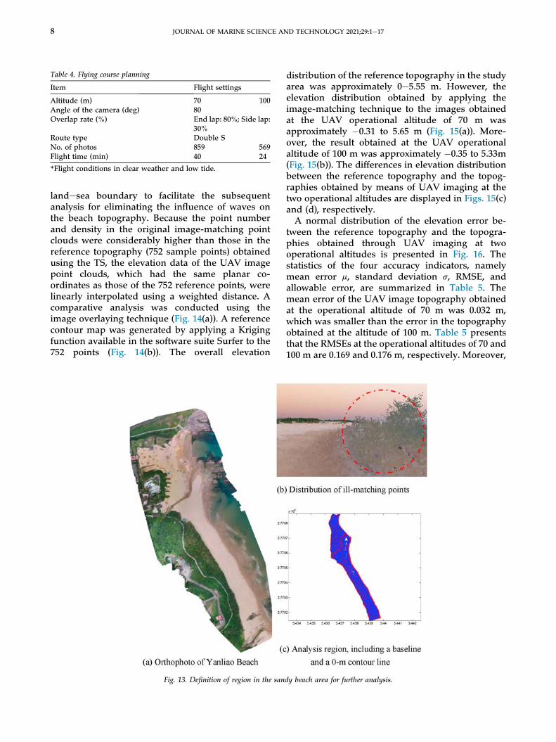
landesea boundary to facilitate the subsequentanalysis for eliminating the influence of waves onthe beach topography. Because the point numberand density in the original image-matching pointclouds were considerably higher than those in thereference topography (752 sample points) obtainedusing the TS, the elevation data of the UAV imagepoint clouds, which had the same planar co-ordinates as those of the 752 reference points, werelinearly interpolated using a weighted distance. Acomparative analysis was conducted using theimage overlaying technique (Fig. 14(a)). A referencecontour map was generated by applying a Krigingfunction available in the software suite Surfer to the752 points (Fig. 14(b)). The overall elevation
distribution of the reference topography in the studyarea was approximately 0e5.55 m. However, theelevation distribution obtained by applying theimage-matching technique to the images obtainedat the UAV operational altitude of 70 m wasapproximately �0.31 to 5.65 m (Fig. 15(a)). More-over, the result obtained at the UAV operationalaltitude of 100 m was approximately �0.35 to 5.33m(Fig. 15(b)). The differences in elevation distributionbetween the reference topography and the topog-raphies obtained by means of UAV imaging at thetwo operational altitudes are displayed in Figs. 15(c)and (d), respectively.A normal distribution of the elevation error be-
tween the reference topography and the topogra-phies obtained through UAV imaging at twooperational altitudes is presented in Fig. 16. Thestatistics of the four accuracy indicators, namelymean error m, standard deviation s, RMSE, andallowable error, are summarized in Table 5. Themean error of the UAV image topography obtainedat the operational altitude of 70 m was 0.032 m,which was smaller than the error in the topographyobtained at the altitude of 100 m. Table 5 presentsthat the RMSEs at the operational altitudes of 70 and100 m are 0.169 and 0.176 m, respectively. Moreover,
Table 4. Flying course planning
Item Flight settings
Altitude (m) 70 100Angle of the camera (deg) 80Overlap rate (%) End lap: 80%; Side lap:
30%Route type Double SNo. of photos 859 569Flight time (min) 40 24
*Flight conditions in clear weather and low tide.
Fig. 13. Definition of region in the sandy beach area for further analysis.
8 JOURNAL OF MARINE SCIENCE AND TECHNOLOGY 2021;29:1e17

the 95% confidence interval for the normal distri-bution statistics was set as the range of allowableerrors to manage the outliers. The allowable errorrange was limited to m±2s. Data points with errorsthat exceeded the allowable error range weremarked with a circle and represented as blunderpoints (Fig. 17). Pearson productemoment correla-tion coefficients were used to investigate the linearrelationship. Figure 18 shows that the correlationcoefficients at the operational altitudes of 70 and100 m are 0.990 and 0.989, respectively, which indi-cate strong correlations. In this figure, most of theblunder points are distributed in the elevation rangeof 0.0e2.0 m, and the maximum elevation differencein the UAV topography obtained from the imagescaptured at the flight altitude of 70 m is 1 m, which islarger than that in the topography obtained from theimages captured at the UAV flight of 100 m. More-over, most of the blunder points occur in the near-shoreline and steep-slope areas, according to resultsshown in Fig. 17.
4.3. Comparison with results obtained using a laserscanner
To investigate the differences between the accu-racies of auxiliary observations on the homogeneousand steep-slope areas of Yanliao Beach, a region ofthe beach with both features was selected(Fig. 19(a)). According to the configuration, GCPswere arranged at the four corners and the center ofthe experimental area. A LIDAR scanner (Fig. 19(b))was used on three sides of the steep-slope area to
scan the topographic elevations along different di-rections to reduce the point cloud vacancies due toobject obstruction. Lateral (gimbal camera) shootingand a higher image-overlap rate were added in theflying course planning to facilitate auxiliary obser-vations (Table 6 and Fig. 20). In Case 1, the followingparameters were used: operational altitude: 70 m,gimbal camera angle: 80�, end lap overlap rate: 80%,side lap overlap rate: 30%, and flying course: dou-ble-S design. In Case 2, a photo-capturing directionwith an angle of 40� was incorporated into theshooting schedule, and the shooting direction wasfixed along the steep-slope area. In Case 3, the endand side lap rates were set to 90% and 50%,respectively. The number of point clouds acquiredusing the LIDAR scanner should generally be lowerthan the GSD (3.2 cm) of the UAV images capturedat the operational altitude of 70 m. Therefore, thehorizontal and vertical intervals were set to3 � 3 cm2 for obtaining the point clouds of thereference topography.The results of Case 1, 2, and 3 and LIDAR mea-
surements were imported into the Pix4Dmapperapplication to generate point cloud data (Fig. 21) andcontour maps for presenting the derived topog-raphy results (Fig. 22). The area along the 1.5-mcontour line was fragmented in the point-cloud-matching UAV images, which indicated that imagematching in the homogeneous region was inaccu-rate. To investigate the difference between theelevation distributions generated using the LIDARpoint clouds of the reference topography and thosegenerated using the settings in different cases, two
Fig. 14. Reference contour map interpolated using 752 points.
JOURNAL OF MARINE SCIENCE AND TECHNOLOGY 2021;29:1e17 9

types of topographic maps were inlaid (Fig. 23).Compared with the elevation difference distribu-tions in other two cases (Case 1 and 3), the elevationdifference distribution in Case 2 was substantiallyreduced because tilt UAV photographs of the steep-slope area were included in the computation. Sixequally spaced sections were plotted at identical
intervals on the topographic maps of LIDAR, Case 1,2, and 3 to compare the elevation differences(Fig. 24). For the elevation range of 2e4 m in thesteep-slope area, the elevation distributionsmeasured in Case 1, 2, and 3 were consistent withthe reference topography measured using LIDAR.The elevation ranged from 1 to 1.8 m in sections S1,
Fig. 15. UAV contour results and elevation difference distributions.
10 JOURNAL OF MARINE SCIENCE AND TECHNOLOGY 2021;29:1e17

Fig. 16. Elevation error distribution at two flight altitudes.
Table 5. Statistics of four accuracy indicators for two UAV image topographies
Altitude (m) Mean error m (m) Standard deviation s(m) RMSE (m) Allowable error (m±2s)(m)
Min. Max.
70 0.032 0.166 0.169 �0.299 0.365100 0.073 0.160 0.176 �0.246 0.393
Fig. 17. Data points with gross error in UAV image topography.
JOURNAL OF MARINE SCIENCE AND TECHNOLOGY 2021;29:1e17 11

S2, and S3 for Case 1, 2, and 3. The elevation dis-tribution was irregular and inconsistent because theUAV image matching was inaccurate. For Case 1and 3, although the overlap rate increased from 80%to 90%, the problem of inaccurate image matchingwas unsolved. The elevation ranged from 1 to 1.8 min section S4, S5, and S6 for Case 1, 2, and 3. Theoverall elevation errors in the topographies ob-tained using UAV imaging were smaller than that ofthe reference topography.
The measurement errors were analyzed in termsof statistical indicatorsdmean error, standard de-viation, RMSE, and Pearson productemoment cor-relation coefficientdto compare the referencetopography obtained using a LIDAR scanner andthe topographies obtained using UAV imagematching. The statistical results of each accuracyindicator were computed and are presented in Table7 and Figs. 25e27. The mean errors in Case 1, 2, and3 were �0.049, �0.058, and �0.063, respectively, andthe corresponding standard deviations were 0.106,0.088, and 0.102. The results of the UAV imagemeasurement, which were consistent with the re-sults obtained in the previous section, indicated thata few of the elevation measurements were lowerthan the corresponding elevations in the referencetopography. Standard deviation represents datadispersion. Moreover, the smaller standard devia-tion of Case 2 revealed that the incorporation oflateral shooting increased the mapping accuracythan those in Case 1 and 3. The RMSEs of Case 1, 2,and 3 were 0.116, 0.106, and 0.119 m, respectively.These values indicated that the RMSE of Case 2, in
Fig. 18. Distribution of Pearson productemoment correlation coefficient at two operational altitudes.
Fig. 19. Configuration of auxiliary observation.
Table 6. Planning of flying course for auxiliary observation
Item Case-1 Case-2 Case-3
Angle of camera (deg) 80 80þ45
80
Overlap rate (%) End lap 80 90Side lap 30 50
Route type Double SNo. of photos 59 72 96Time (min) 2 3 4GSD (cm) 3.14 3.08 3.14
*Limit UAV operational altitude to 70 m.
12 JOURNAL OF MARINE SCIENCE AND TECHNOLOGY 2021;29:1e17
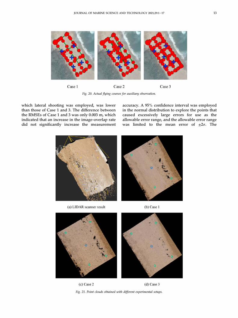
which lateral shooting was employed, was lowerthan those of Case 1 and 3. The difference betweenthe RMSEs of Case 1 and 3 was only 0.003 m, whichindicated that an increase in the image-overlap ratedid not significantly increase the measurement
accuracy. A 95% confidence interval was employedin the normal distribution to explore the points thatcaused excessively large errors for use as theallowable error range, and the allowable error rangewas limited to the mean error of ±2s. The
Fig. 20. Actual flying courses for auxiliary observation.
Fig. 21. Point clouds obtained with different experimental setups.
JOURNAL OF MARINE SCIENCE AND TECHNOLOGY 2021;29:1e17 13

correlations between the elevation of the referencetopography and the elevations obtained using UAVimagery in Case 1, 2, and 3 were 0.988, 0.991, and0.989, respectively (Figs. 25e27). These values indi-cate a high level of correlation. Numerous outlierswere found in the distribution maps in the elevationrange of 1e1.8 mdconsistent with the aforemen-tioned test area that exhibited inaccurate imagematching.
This section explores the difference between themean errors in elevation in the reference topogra-phies obtained using the TS and a LIDAR scanner.The comparison results revealed that the meanerror values in the UAV image topographiescomputed using a TS and a LIDAR were positiveand negative, respectively. In practical applications,the TS measures elevation by using the signals re-flected by a survey prism affixed to a pole. The pole
Fig. 22. Contour maps derived using different setups.
Fig. 23. Color rendering for DSM difference results of (a) Case 1, (b) Case 2, and (c) Case 3.
14 JOURNAL OF MARINE SCIENCE AND TECHNOLOGY 2021;29:1e17

is inserted in the sand during measurement. Theinsertion depth of the prism pole can be 3e5 cm. ALIDAR scanner measures elevation by emitting alaser beam toward a measurement point on a soilsurface. Artificial and systematic errors, such as theerrors due to control surveying or those introducedby measurement personnel, cause differences
between the point heights measured using the twomethods. Both LIDAR and UAV imagery areremote-sensing techniques that acquire data basedon the surface characteristics of an object. The re-sults of this study were presented as dense pointclouds, and they were relatively consistent.
Fig. 24. Elevation profiles of sections S1eS6.
Table 7. Error indicators pertaining to elevations in different cases
Item r-square Mean error (m) Standard deviation (m) RMSE (m) GCP-RMSE (m) Allowable error(m)
Min. Max.
Case-1 0.988 �0.049 0.106 0.116 0.011 �0.259 0.162Case-2 0.991 �0.058 0.088 0.106 0.008 �0.236 0.119Case-3 0.989 �0.063 0.102 0.119 0.007 �0.267 0.141
Fig. 25. Correlation and elevation error distribution in Case 1.
JOURNAL OF MARINE SCIENCE AND TECHNOLOGY 2021;29:1e17 15

5. Conclusion
UAV imaging technology has various advantages,such as high portability, low operational altitude, andhigh mobility, and it can be used for monitoring andmanaging coastal areas. This technology was used inthe present study to monitor beach topography. Insitu data were acquired through a UAV-mountednon-metric camera and GCPs. Pix4Dmapper, a UAVimage postprocessing software application, was usedto identify the feature points to obtain the informa-tion pertaining to the overall change in sand topog-raphy. Themethod proposed in this study can reducethe amount of human resources required by con-ventional direct observation methods, in addition toreducing the indirect observation costs. TheUAV,TS,and laser scanner used in this research cost approx-imately NT$45,000, NT$20,000eNT$100,000, andNT$200,000eNT$600,000 (depending on the laserpower), respectively.The measurement configuration and flying course
planning of this study included a double-S-type
flying course, camera tilt angle of �80�, an end lapoverlap rate of 80%, a side lap overlap rate of 30%,UAV operational altitudes lower than 100 m, andmeasured RMSEs of less than 20 cm. Comparedwith the reference topography measured using theTS, the topography measured using UAV imaging atthe operational altitudes of 70 and 100 m exhibitedRMSEs of 16.9 and 17.6 cm, respectively. Comparedwith the reference topography that was measuredusing a LIDAR scanner, different photographyconditions effectively increased the measurementaccuracy to an RMSE of 10.6 cm when the mea-surement was conducted at the UAV operationalaltitude of 70 m. However, gross errors were mostlygenerated from the data of landesea boundary,steep-slope areas, and areas in which the beachfeature points were inaccurately matched. The er-rors were considerably influenced by the waves atdifferent times and the weather conditions at thetime when the UAV image measurement systemwas used to estimate the 0-m contour line. Thus,various inconsistencies were observed between the
Fig. 26. Correlation and elevation error distribution in Case 2.
Fig. 27. Correlation and elevation error distribution in Case 3.
16 JOURNAL OF MARINE SCIENCE AND TECHNOLOGY 2021;29:1e17
reference topography and the UAV imagery results.Moreover, the maximum error was up to 10 m. If theUAV image topography contour of 0 m is used as areference for coastline measurement in the future,the authors of this study suggest that UAV aerialphotography should be performed when the oceanis quiet and the weather is breezy. UAV imagesshould be captured when the tide level is the lowestin the day to reduce the effect of waves. Futurestudies can consider incorporating the coastlineimage monitoring system to determine an appro-priate landesea boundary to reduce the errors thatinfluence UAV image measurements.
Acknowledgement
We are grateful to the participants of the researchteam. We thank the experts and scholars forreviewing, editing, and providing valuable com-ments on the manuscript.
References
[1] Casella E, Rovere A, Pedroncini A, Mucerino L, Casella M,Cusati AL, et al. Study of wave runup using numericalmodels and low-altitude aerial photogrammetry: a tool forcoastal management. Estuar Coast Shelf Sci 2014;149:160e7.
[2] Casella E, Rovere A, Pedroncini A, Stark CP, Casella M,Ferrari M, et al. Drones as tools for monitoring beachtopography changes in the Ligurian Sea (NW Mediterra-nean). Geo Mar Lett 2016;36:151e63.
[3] Chiang S-P. UAV photogrammetry for beach topographysurveying. Master Thesis. National Taiwan Ocean Univer-sity, Department of Harbor and River Engineering; 2017.
[4] Drummond Christopher D, Mitchell D Harley, Turner Ian L,Matheen ANashwan A, Glamore William C. UAV applica-tions to coastal engineering. In: Australasian Coasts & PortsConference; 2015. p. 15e8.
[5] Fang H-M, Hsiao S-S, Yang Y-C, Liao S-Y. Application ofbinocular stereo imaging for the beach topographicsurveying. In: Proceeding of 36th Ocean Engineering Con-ference in Taiwan; 2014. p. 647e52 (in Chinese).
[6] Mancini Francesco, Dubbini Marco, Gattelli Mario,Stecchi Francesco, Fabbri Stefano, Gabbianelli Giovanni.Using unmanned aerial vehicles (UAV) for high-resolutionreconstruction of topography: the structure from motionapproach on coastal environments. Rem Sens 2013;5:6880e98.
[7] Harwin S, Lucieer A. Assessing the accuracy of georefer-enced point clouds produced viamulti-view stereopsis fromunmanned aerial vehicle (UAV) imagery. Rem Sens 2012;4:1573e99.
[8] Holland KT, Holman RA, Lippmann TC, Stanley J, Plant N.Practical use of video imagery in nearshore oceanographicfield studies. IEEE J Ocean Eng 1997;22(1):81e92.
[9] Holman RA, Stanley J. The history and technical capabilitiesof Argus. Coast Eng 2007;54:477e91.
[10] Hsiao Y-H, Chen H-T, Chuang S-C, Huang M-C. Pre-liminary application of a Pan/tilt camera in coastal imageResearch. In: Proceeding of the 30th Ocean EngineeringConference in Taiwan; 2008. p. 745e50 (in Chinese).
[11] Hsu C-H, Lin W-H, Huang Y-T, Lin S-H, Lin C-J. “Researchon technological innovation of topographic maps updatemaintenance,” Ministry of the interior research projectReport No. 103-301000100G002. 2014.
[12] Turner Ian L, Harley Mitchell D, Drummond Christopher D.UAVs for coastal surveying. Coast Eng 2016;114:19e24.
[13] Liao S-Y. Application of binocular stereo imaging for thebeach topographic surveying. National Taiwan Ocean Uni-versity, Department of Harbor and River Engineering; 2014.Master Thesis.
[14] National Land Surveying and Mapping Center, Ministry ofthe Interior, R.O.C.. Operation manual for encrypted controland Tugen measurement using virtual base station real-timedynamic positioning technology. 2010 (in Chinese).
[15] Plant NG, Holman RA. Intertidal beach profile estimationusing video images. Mar Geol 1997;140:1e24.
[16] Rau J-Y, Chen C-Y, Jhan J-P, Liu K, Lee W. Accuracy ana-lyses of UAV photogrammetry and direct georeferencing.Taiwan J Geoinf 2014;2(1):1e22.
[17] Su B-H, Hsiao Y-S, Wang J-M, Chen S-C. A feasibility studyon unmanned aircraft systems for high accuracy mapping.J Chin Soil Water Conserv 2013:1e12.
JOURNAL OF MARINE SCIENCE AND TECHNOLOGY 2021;29:1e17 17