be8255-basic electrical ,electronics and measurement ... basic electrical... · kvl states that the...
TRANSCRIPT

BE8255-BASIC ELECTRICAL ,ELECTRONICS AND MEASUREMENT ENGINEERING
UNIT I ELECTRICAL CIRCUIT ANALYSIS
PART A
1. State Ohm’s Law.may 2017
The potential difference across any two ends of a conductor is directly
proportional to the current flowing between the two ends provided the
temperature of the conductor remains constant.
2. State Krichoff’s Law ,may2015
KVL states that the algebraic sum of voltages in a closed path is zero.
KCL states that the algebraic sum of currents in a node is zero.
3. Distinguish between a mesh and a loop of a circuit.
A mesh is a loop that does not contain other loops. All meshes are loop, but
all loops are not meshes. A loop is any closed path of branches.
4. Write down the formula for a star connected network is converted into a
delta network?
RA=( R1 R2)/( R1 +R2+ R3) RB=( R1 R3)/( R1 +R2+ R3) RC=( R2 R3)/( R1
+R2+ R3)
5. What is reactive power?
If we consider the circuit as purely inductive the output power is
reactive power. Its unit is VAR.
6. Define Form factor and Crest factor.
Form factor= RMS value / Average Value
Crest(peak) factor=Maximum Value / RMS value

7. What are the three types of power used in a a.c circuit?
8. Define RMS value.
The effective value of an alternating current is that value of steady ,direct
current which produces the same heat as that produced by the alternating current
when passed which produces the same heat as that produced by the alternating
current when passed through the same resistance for the same interval of time.
9. What is meant by eddy current damping?
When the conductor moves in a magnetic field an emf is induced in it and if
a closed path is provided ,a current flows known as eddy current. This current
intersect with the magnetic field to produce an electromagnetic torque , which
opposes the deflecting torque.
10. Which type of instrument is called as universal instrument?
The moving iron instrument are known as universal instruments, because
these instruments can be used for AC and DC.

PART B
1.Explain the Star to Delta transformation in detailed manner?
Star Delta Transformations allow us to convert impedances connected together
from one type of connection to another. Standard 3-phase circuits or networks take
on two major forms with names that represent the way in which the resistances are
connected, a Star connected network which has the symbol of the letter, Υ (wye)
and aDelta connected network which has the symbol of a triangle, (delta).
If a 3-phase, 3-wire supply or even a 3-phase load is connected in one type
of configuration, it can be easily transformed or changed it into an equivalent
configuration of the other type by using either the Star Delta
Transformation or Delta Star Transformation process.
Pi-connected and Equivalent Delta Network.

These Circuit Transformations allow us to change the three connected
resistances (or impedances) by their equivalents measured between the terminals 1-
2, 1-3 or 2-3 for either a star or delta connected circuit.
For example, resistor A is given as:
A= (PQ + QR + RP) / R with respect to terminal 3 and resistor B is given as:
B = (PQ + QR + RP) / Q with respect to terminal 2 and resistor C given as:
B = (PQ + QR + RP) / R with respect to terminal 1.
Star Delta Transformation allows us to convert one type of circuit
connection into another type in order for us to easily analyze the circuit and star
delta transformation techniques can be used for either resistances or impedances.
2.Three resistances of values 2Ω, 3Ω and 5Ω are connected in series across 20
V, D.C supply Calculate (a) equivalent resistance of the circuit (b) the total
current of the circuit (c) the voltage drop across each resistor and (d) the
power dissipated in each resistor?
Given data:
R1 = 2Ω
R2 = 3Ω
R3 = 5Ω
V = 20V

To find:
R T =?
I T =?
V1, V2, V3 =?
P1, P2, P3 =?
Formula used:
RT = R1+R2+R3 (series connection)
IT = VT / RT
V1 = R1*I1
V2= R2*I2
V3 = R3*I3
P1=V1*I1
P2=V2*I2
P3=V3*I3
Solution:
RT = R1+R2+R3 = 2+3+5
RT = 10Ω
IT = VT / RT = 20 / 10
IT = 2 A
In series connection I1 = I2 = I3 = IT = 2A
V1 = I1*R1 = 2*2
V1 = 4 V
V2 = I2*R2 = 2*3
V2 = 6 V
V3 = I3*R3 = 5*2
V3 = 10V

P1 = V1*I1
= 4*2
P1 = 8W
P2 = V2*I2
= 6*2
P2 = 12W
P3 = V3*I3 = 10*2
P3 = 20W
Result:
(a). Equivalent resistance of the circuit RT = 10Ω
(b). The total current of the circuit IT = 2A
(c). Voltage drop across each resistor V1 = 4 V, V2 = 6 V, V3 = 10V
(d). The power dissipated in each resistor P1 = 8W, P2 = 12W, P3 = 20W
3.Explain the Kirchhoff's Law in detailed manner?
Kirchhoff's Current Law:
First law (Current law or Point law): Statement:
The sum of the currents flowing towards any junction in an electric circuit
equal to the sum of currents flowing away from the junction.
Kirchhoff's Current law can be stated in words as the sum of all currents
flowing into a node is zero. Or conversely, the sum of all currents leaving a node
must be zero. As the image below demonstrates, the sum of currents Ib, Ic, and Id,
must equal the total current in Ia. Current flows through wires much like water
flows through pipes. If you have a definite amount of water entering a closed pipe
system, the amount of water that enters the system must equal the amount of water
that exists the system. The number of branching pipes does not change the net
volume of water (or current in our case) in the system.

Kirchhoff’s law:
Kirchhoff's Voltage Law:
Second law (voltage law or Mesh law): Statement:
In any closed circuit or mesh, the algebraic sum of all the electromotive
forces and the voltage drops is equal to zero.
Kirchhoff's voltage law can be stated in words as the sum of all voltage
drops and rises in a closed loop equals zero. As the image below demonstrates,
loop 1 and loop 2 are both closed loops within the circuit. The sum of all voltage
drops and rises around loop 1 equals zero, and the sum of all voltage drops and
rises in loop 2 must also equal zero. A closed loop can be defined as any path in
which the originating point in the loop is also the ending point for the loop. No
matter how the loop is defined or drawn, the sum of the voltages in the loop must
bezero.

4.Explain the superposition theorem in detailed manner?
The superposition theorem is unquestionably one of the most powerful in
this field. It has such widespread application that people often apply it without
recognizing that their maneuvers are valid only because of this theorem.
In general, the theorem can be used to do the following:
• Analyze networks such as introduced in the last chapter that have two or
more sources that are not in series or parallel.
• Reveal the effect of each source on a particular quantity of interest.
• For sources of different types (such as dc and ac, which affect the
parameters of the network in a different manner) and apply a separate analysis for
each type, with the total result simply the algebraic sum of the results.
• Become familiar with the superposition theorem and its unique ability to
separate the impact of each source on the quantity of interest.
• Be able to apply Thévenin’s theorem to reduce any two-terminal, series-
parallel network with any number of sources to a single voltage source and series
resistor.
• Become familiar with Norton’s theorem and how it can be used to reduce
any two-terminal, seriesparallel network with any number of sources to a single
current source and a parallel resistor.
The superposition theorem states the following: The current through, or
voltage across, any element of a network is equal to the algebraic sum of the
currents or voltages produced independently by each source. In other words, this
theorem allows us to find a solution for a current or voltage using only one source
at a time. Once we have the solution for each source, we can combine the results to
obtain the total solution. The term algebraic appears in the above theorem
statement because the currents resulting from the sources of the network can have
different directions, just as the resulting voltages can have opposite polarities. If
we are to consider the effects of each source, the other sources obviously must be
removed. Setting a voltage source to zero volts is like placing a short circuit across
its terminals. Therefore, when removing a voltage source from a network
schematic, replace it with a direct connection (short circuit) of zero ohms. Any
internal resistance associated with the source must remain in the network. Setting a
current source to zero amperes is like replacing it with an open circuit. Therefore,
when removing a current source from a network schematic, replace it by an open

circuit of infinite ohms. Any internal resistance associated with the source must
remain in the network.
5. Explain the thevenin’s theorem in detailed manner?
Thévenin’s theorem The next theorem to be introduced, Thévenin’s theorem,
is probably one of the most interesting in that it permits the reduction of complex
networks to a simpler form for analysis and design.
In general, the theorem can be used to do the following:
• Analyze networks with sources that are not in series or parallel.
• Reduce the number of components required to establish the same
characteristics at the output terminals.
Thévenin’s Theorem Procedure Preliminary:
1. Remove that portion of the network where the Thévenin equivalent circuit
is found. this requires that the load resistor RL be temporarily removed from the
network.
2. Mark the terminals of the remaining two-terminal network. (The
importance of this step will become obvious as we progress through some complex
networks.) RTh
3. Calculate RTh by first setting all sources to zero (voltage sources are
replaced by short circuits and current sources by open circuits) and then finding the
resultant resistance between the two marked terminals. (If the internal resistance of
the voltage and/or current sources is included in the original network, it must
remain when the sources are set to zero.) Eth
4. Calculate ETh by first returning all sources to their original position and
finding the open-circuit voltage between the marked terminals. (This step is
invariably the one that causes most confusion and errors. In all cases, keep in mind
that it is the open-circuit
5. Draw the Thévenin equivalent circuit with the portion of the circuit
previously removed replaced between the terminals of the equivalent circuit.

6. Explain the norton’s theorem in detailed manner?
The theorem states the following: Any two-terminal linear bilateral dc
network can be replaced by an equivalent circuit consisting of a current source
and a parallel resistor
Norton’s Theorem Procedure Preliminary:
1. Remove that portion of the network across which the Norton equivalent
circuit is found.
2. Mark the terminals of the remaining two-terminal network. RN:
3. Calculate RN by first setting all sources to zero (voltage sources are
replaced with short circuits and current sources with open circuits) and then
finding the resultant resistance between the two marked terminals. (If the internal
resistance of the voltage and/or current sources is included in the original
network, it must remain when the sources are set to zero.) Since RN = RTh, the
procedure and value obtained using the approach described for Thévenin’s
theorem will determine the proper value of RN. IN:
4. Calculate IN by first returning all sources to their original position and
then finding the short-circuit current between the marked terminals. It is the same
current that would be measured by an ammeter placed between the marked
terminals. Conclusion:
5. Draw the Norton equivalent circuit with the portion of the circuit
previously removed replaced between the terminals of the equivalent circuit.
7. Explain the maximum power transfer theorem in detailed manner?
maximum power transfer theorem When designing a circuit, it is often
important to be able to answer one of the following questions:
What load should be applied to a system to ensure that the load is receiving
maximum power from the system
Conversely: For a particular load, what conditions should be imposed on the
source to ensure that it will deliver the maximum power available

Even if a load cannot be set at the value that would result in maximum
power transfer, it is often helpful to have some idea of the value that will draw
maximum power so that you can compare it to the load at hand.
For instance, if a design calls for a load of 100 Ω, to ensure that the load
receives maximum power, using a resistor of 1 Ω or 1 kΩ results in a power
transfer that is much less than the maximum possible. However, using a load of
82 Ω or 120 Ω probably results in a fairly good level of power transfer.
Fortunately, the process of finding the load that will receive maximum
power from a particular system is quite straightforward due to the maximum
power transfer theorem, which states the following: A load will receive
maximum power from a network when its resistance is exactly equal to the
Thévenin resistance of the network , for the Thévenin equivalent circuit in when
the load is set equal to the Thévenin resistance, the load will receive maximum
power from the network. with RL = RTh,
we can determine the maximum power delivered to the load by first finding
the current: IL = ETh RTh + RL = ETh RTh + RTh = ETh 2RTh Then we
substitute into the power equation: PL = I 2 LRL = a ETh 2RTh b 2 (RTh) = E2
ThRTh 4R2 Th and PLmax = E 2 Th 4RTh To demonstrate that maximum power
is indeed transferred to the load under the conditions defined above, consider the
Thévenin equivalent circuit in Before getting into detail, however, if you were to
guess what value of RL would result in maximum power transfer to RL, you
might think that the smaller the value of RL, the better it is because the current
reaches a maximum when it is squared in the power equation. The problem is,
however, that in the equation PL = I 2 LRL, the load resistance is a multiplier. As
it gets smaller, it forms a smaller product. Then again, you might suggest larger
values of RL because the output voltage increases, and power is determined by
PL = V 2 L /RL. This time, however, the load resistance is in the denominator of
the equation and causes the resulting power to decrease. A balance must
obviously be made between the load resistance and the resulting current or
voltage. The following discussion shows that maximum power transfer occurs
when the load voltage and current are one-half their maximum possible values.
For the circuit in Fig. 9.85, the current through the load is determined by IL =
ETh RTh + RL = 60 V 9 Ω + RL The voltage is determined by VL = RLETh RL
+ RTh = RL(60 V) RL + RTh and the power by PL = I 2 LRL = a 60 V 9 Ω + RL
b 2 (RL) = 3600RL (9 Ω + RL) 2 If we tabulate the three quantities versus a
range of values for RL from 0.1 Ω to 30 Ω, If the load applied is less than the
Thévenin resistance, the power to the load will drop off rapidly as it gets smaller.

However, if the applied load is greater than the Thévenin resistance, the power to
the load will not drop off as rapidly as it increases.
8. Explain the parallel circuit analysis in detailed manner?
Resistors in Parallel Consider a circuit with 3 resistors in parallel (such as
the circuit below, if N = 3). Since the voltages across all the parallel elements in a
circuit are the same (E = V1 = V2=V3),
This result can be generalized to provide the total resistance of any number
of resistors in parallel:
Special Case: Two Resistors in Parallel For only two resistors connected in
parallel, the equivalent resistance may be found by the product of the two values
divided by the sum:
Current through resistors in parallel. The total current I is shared by the
resistors in inverse proportion to their resistances. Stated another way: “More
current follows the path of least resistance.”
Extreme cases for current division: Current Divider Rule The Current
Divider Rule (CDR) allows us to determine how the current flowing into a node
is split between the various parallel resistors.
Compare the formulas for the voltage divider rule and the current divider
rule. Special Case: Two resistors in parallel. For only two resistors in parallel:
open circuit short circuit
Special Case: If current enters a parallel network with a number of equal
resistors, the current will split equally between the resistors. Note:
In a parallel network, the smallest value resistor will have the largest
current. Analysis of Parallel Circuits To analyze parallel circuits we should use
the following guidelines:
1. Voltage across all branches is the same as the source voltage
2. Determine current through each branch using Ohm’s Law
3. Find the total current using Kirchhoff’s Current Law

9. Explain the inductive networks in detailed manner?
Pure Inductive circuits:
This simple circuit above consists of a pure inductance of L Henries ( H ),
connected across a sinusoidal voltage given by the expression: V(t) = Vmax sin ωt.
When the switch is closed this sinusoidal voltage will cause a current to flow and
rise from zero to its maximum value. This rise or change in the current will induce
a magnetic field within the coil which in turn will oppose or restrict this change in
the current.
But before the current has had time to reach its maximum value as it would
in a DC circuit, the voltage changes polarity causing the current to change
direction. This change in the other direction once again being delayed by the self-
induced back emf in the coil, and in a circuit containing a pure inductance only, the
current is delayed by 90o.
The applied voltage reaches its maximum positive value a quarter ( 1/4ƒ ) of
a cycle earlier than the current reaches its maximum positive value, in other words,
a voltage applied to a purely inductive circuit “LEADS” the current by a quarter of
a cycle or 90o as shown below.

The instantaneous voltage across the resistor, VR is equal to the supply
voltage, Vt and is given as:
VL = Vmax sin (ωt + 90)
IL = V / XL
XL = 2πfL
10. Explain the capacitive networks in detailed manner?
Pure Capacitive circuits:
When the switch is closed in the circuit above, a high current will start to
flow into the capacitor as there is no charge on the plates at t = 0. The sinusoidal
supply voltage, V is increasing in a positive direction at its maximum rate as it
crosses the zero reference axis at an instant in time given as 0o. Since the rate of
change of the potential difference across the plates is now at its maximum value,

the flow of current into the capacitor will also be at its maximum rate as the
maximum amount of electrons are moving from one plate to the other.
As the sinusoidal supply voltage reaches its 90o point on the waveform it
begins to slow down and for a very brief instant in time the potential difference
across the plates is neither increasing nor decreasing therefore the current
decreases to zero as there is no rate of voltage change. At this 90opoint the potential
difference across the capacitor is at its maximum ( Vmax ), no current flows into the
capacitor as the capacitor is now fully charged and its plates saturated with
electrons.
At the end of this instant in time the supply voltage begins to decrease in a
negative direction down towards the zero reference line at 180o. Although the
supply voltage is still positive in nature the capacitor starts to discharge some of its
excess electrons on its plates in an effort to maintain a constant voltage. These
results in the capacitor current flowing in the opposite or negative direction.
When the supply voltage waveform crosses the zero reference axis point at
instant 180o, the rate of change or slope of the sinusoidal supply voltage is at its
maximum but in a negative direction, consequently the current flowing into the
capacitor is also at its maximum rate at that instant. Also at this 180o point the
potential difference across the plates is zero as the amount of charge is equally
distributed between the two plates.
Then during this first half cycle 0o to 180o, the applied voltage reaches its
maximum positive value a quarter (1/4ƒ) of a cycle after the current reaches its
maximum positive value, in other words, a voltage applied to a purely capacitive
circuit “LAGS” the current by a quarter of a cycle or 90o
IC = Imax sin (ωt + 90)
IL = V / XC
XC = 1 / 2πfC

UNIT II ELECTRICAL MACHINES
PART A
1. What is an electric generator?
An electrical machine, which converts mechanical energy into electrical
Energy, is called as electric generator.
2. What is an electric motor?
An electrical machine, which converts electrical energy into mechanical
Energy, is called as electric motor.
3.What is the function yoke?
It serves the purpose of outermost cover of the dc machine. So that
the insulating material get protected from harmful atmospheric elements like
moisture, dust and various gases like SO2, acidic fumes etc.It provides mechanical
support to the poles.
4. Define voltage transformation ratio?dec2015
The ratio of secondary induced emf to primary induced emf is called as voltage
regulation ratio devoted by K.
5.Write down the emf equation for d.c generator.

Where
P = number of poles
Z = Total number of conductors
A = number of parallel paths
Ф = flux per pole
N = speed in rpm
6. what is the principle of DC motor?
Whenever a current carrying conductor placed in a magnetic field, it
experiences a mechanical force.
7. List the different types of DC motor.
o DC series motor
o DC Shunt motor
o DC Compound motor
Long shunt compound motor
Short shunt compound motor
8.Give the torque equation of a DC motor.
Ta=0.159fIa.PZ/A N-m
Ia - Armature current
P - Number of poles
Z - Total number of conductors
A -Number of parallel paths
9.List out the characteristics of DC motor.
i. Torque-Armature current characteristics (T VS Ia)
ii. Speed-Armature current characteristics (N VS Ia)

10. What are all the applications of DC motor?
Blowers and fans
Centrifugal and reciprocating pumps
Lathe machines
Machine tools
Milling machines
Drilling machines
PART B
1. write the notes on construction of d.c. machines in clear manner?
Frame
Frame is the stationary part of a machine on which the main poles and
commutator poles are bolted and it forms the supporting structure by connecting
the frame to the bed plate.

poles:
Inter-poles are small additional poles located in between the main poles.
These can be solid, or laminated just as the main poles. These are also
fastened to the yoke by bolts.
Armature
The armature is where the moving conductors are located. The armature is
constructed by stacking laminated sheets of silicon steel. Thickness of these
lamination is kept low to reduce eddy current losses.
Field windings:
Hence the armature windings are in general pre-formed, taped and lowered
into the open slots on the armature. In the case of small machines, they can be hand
wound. The coils are prevented from flying out due to the centrifugal forces by
means of bands of steel wire on the surface of the rotor in small groves cut into it.
In the case of large machines slot wedges are additionally used to restrain the coils
from flying away.
Commutator:
Commutator is the key element which made the d.c. machine of the present
day possible. It consists of copper segments tightly fastened together with
mica/micanite insulating separators

on an insulated base. The whole commutator forms a rigid and solid assembly of
insulated copper strips and can rotate at high speeds.
Brush and brush holders:
The brushes are kept pressed on the commutator with the help of springs.
This is to ensure proper contact between the brushes and the commutator even
under high speeds of operation. Jumping of brushes must be avoided to ensure arc
free current collection and to keep the brushcontact drop low. Other mechanical
parts End covers, fan and shaft bearings form other important mechanical parts.
End Shields or Bearings
If the armature diameter does not exceed 35 to 45 cm then in addition to
poles end shields or frame head with bearing are attached to the frame.If the
armature diameter is greater than 1m pedestral type bearings are mounted on the
machine bed plate outside the frame.
2. write the notes on principle of d.c. machines in clear manner?
PRINCIPLE OF OPERATION
DC generator converts mechanical energy into electrical energy. when a
conductor move in a magnetic field in such a way conductors cuts across a
magnetic flux of lines and emf produces in a generator and it is defined by faradays
law of electromagnetic induction emf causes current to flow if the conductor
circuit is closed. The pole pieces (marked N and S) provide the magnetic field. The
pole pieces are shaped and positioned as shown to concentrate the magnetic field
as close as possible to the wire loop. The loop of wire that rotates through the field
is called the ARMATURE. The ends of the armature loop are connected to rings
called SLIP RINGS. They rotate with the armature.
The brushes, usually made of carbon, with wires attached to them, ride against the
rings. The generated voltage appears across these brushes. The elementary
generator produces a voltage in the following manner (fig. 1-3). The armature loop
is rotated in a clockwise direction. The initial or starting point is shown at position
A. (This will be considered the zero-degree position.) At 0º_ the armature loop is
perpendicular to the magnetic field. The black and white conductors of the loop are
moving parallel to the field. The instant the conductors are moving parallel to the
magnetic field, they do not cut any lines of flux. Therefore, no emf is induced in
the conductors, and the meter at position A indicates zero. This position is called

the NEUTRAL PLANE. As the armature loop rotates from position A (0º) to
position B (90º), the conductors cut through more and more lines of flux, at a
continually increasing angle. At 90º they are cutting through a maximum number
of lines of flux and at maximum angle. The result is that between 0º and 90º , the
induced emf in the conductors builds up from zero to a maximum value. Observe
that from 0º_ to 90º_, the black conductor cuts DOWN through the field. At the
same time the white conductor cuts UP through the field.
The induced emfs in the conductors are series-adding. This means the resultant
voltage across the brushes (the terminal voltage) is the sum of the two induced
voltages. The meter at position B reads maximum value. As the armature loop
continues rotating from 90º_ (position B) to 180º_ (position C), the conductors
which were cutting through a maximum number of lines of flux at position B now
cut through fewer lines. They are again moving parallel to the magnetic field at
position C. They no longer cut through any lines of flux. As the armature rotates
from 90º_ to 180º_, the induced voltage will decrease to zero in the same manner
that it increased during the rotation from 0º_ to 90º_. The meter again reads zero.
From 0º_ to 180º_ the conductors of the armature loop have been moving in the
same direction through the magnetic field. Therefore, the polarity of the induced

voltage has remained the same. This is shown by points A through C on the graph.
3. Explain the E.M.F equations of d.c. machines in clear manner?
E.M.F EQUATION
Let
Φ = flux/pole in weber
Z = total number of armture conductors = No.of slots x No.of conductors/slot
P = No.of generator poles
A = No.of parallel paths in armature
N = armature rotation in revolutions per minute (r.p.m) E = e.m.f induced in any
parallel path in armature
Generated e.m.f Eg = e.m.f generated in any one of the parallel paths i.e E.
Average e.m.f geneated /conductor = dΦ/dt volt (n=1)
Now, flux cut/conductor in one revolution dΦ = ΦP Wb No.of
revolutions/second = N/60

Time for one revolution, dt = 60/N second
Hence, according to Faraday's Laws of Electroagnetic Induction,
E.M.F generated/conductor is
For a simplex wave-wound generator
No.of parallel paths = 2
No.of conductors (in series) in one path = Z/2
E.M.F. generated/path is
For a simplex lap-wound generator
No.of parallel paths = P
No.of conductors (in series) in one path = Z/P
E.M.F.generated/path
In general generated e.m.f
where A = 2 for simplex wave-winding A = P for simplex lap-winding

4. Explain the working principle of transformer in clear manner?
BASIC WORKING PRINCIPLE OF TRANSFORMER
A transformer can be defined as a static device which helps in the
transformation of electric power in one circuit to electric power of the same
frequency in another circuit. The voltage can be raised or lowered in a circuit, but
with a proportional increase or decrease in the current ratings. The main principle
of operation of a transformer is mutual inductance between two circuits which is
linked by a common magnetic flux. A basic transformer consists of two coils that
are electrically separate and inductive, but are magnetically linked through a path
of reluctance. The working principle of the transformer can be understood from the
figure below.
The core laminations are joined in the form of strips in between the strips
there are some narrow gaps right through the cross-section of the core. These
staggered joints are said to be‘imbricated’. Both the coils have high mutual
inductance. A mutual electro-motive force is induced in the transformer from the
alternating flux that is set up in the laminated core, due to the coil that is connected
to a source of alternating voltage. Most of the alternating flux developed by this
coil is linked with the other coil and thus produces the mutual induced electro-
motive force. The so produced electro-motive force can be explained with the help
of Faraday’s laws of Electromagnetic Induction as

e=M*dI/dt
If the second coil circuit is closed, a current flows in it and thus electrical energy is
transferred magnetically from the first to the second coil.
The alternating current supply is given to the first coil and hence it can be
called as the primary winding. The energy is drawn out from the second coil
and thus can be called as the secondary winding.
In short, a transformer carries the operations shown below:
Transfer of electric power from one circuit to another.
Transfer of electric power without any change in frequency.
Transfer with the principle of electromagnetic induction.
The two electrical circuits are linked by mutual induction
5. Explain the construction of transformer in clear manner?
TRANSFORMER CONSTRUCTION
Two coils of wire (called windings) are wound on some type of core
material. In some cases the coils of wire are wound on a cylindrical or rectangular
cardboard form. In effect, the core material is air and the transformer is called an
AIR-CORE TRANSFORMER. Transformers used at low frequencies, such as 60
hertz and 400 hertz, require a core of low-reluctance magnetic material, usually
iron. This type of transformer is called an IRON-CORE TRANSFORMER. Most
power transformers are of the iron-core type.
The principle parts of a transformer and their functions are:
The CORE, which provides a path for the magnetic lines of flux.
The PRIMARY WINDING, which receives energy from the ac source.
The SECONDARY WINDING, which receives energy from the primary
winding and delivers it to the load.
The ENCLOSURE, which protects the above components from dirt,
moisture, and mechanical damage.

(i) CORE
There are two main shapes of cores used in laminated-steel-core
transformers. One is the HOLLOWCORE, so named because the core is
shaped with a hollow square through the center. This shape of core. Notice
that the core is made up of many laminations of steel it shows how the
transformer windings are wrapped around both sides of the core.
(ii) WINDINGS
the transformer consists of two coils called WINDINGS which are
wrapped around a core. The transformer operates when a source of ac
voltage is connected to one of the windings and a load device is connected to
the other. The winding that is connected to the source is called the
PRIMARY WINDING. The winding that is connected to the load is called
the SECONDARY WINDING. The primary is wound in layers directly on a
rectangular cardboard form.

6. Write the E.M.F equation of transformer in clear manner?
The applied voltage V1 applied to the primary of a transformer, with
secondary open-circuited, be sinusoidal (or sine wave). Then the current I1, due to
applied voltage V1, will also be a sine wave. The mmf N1 I1 and core flux Ø will
follow the variations of I1 closely. That is the flux is in time phase with the current
I1 and varies sinusoidally.
NA = Number of turns in primary
NB = Number of turns in secondary
Ømax = Maximum flux in the core in webers = Bmax X A f = Frequency
of alternating current input in hertz (HZ)
the core flux increases from its zero value to maximum value Ømax in one
quarter of the cycle , that is in ¼ frequency second.
Therefore, average rate of change of flux = Ømax/ ¼ f = 4f ØmaxWb/s
Now, rate of change of flux per turn means induced electro motive force in
volts. Therefore,
average electro-motive force induced/turn = 4f Ømaxvolt
If flux Ø varies sinusoidally, then r.m.s value of induced e.m.f is obtained by
multiplying the average value with form factor.

EA = 4.44f NAØmax = 4.44fNABmA
Similarly, r.m.s value of induced e.m.f in secondary is
EB = 4.44f NB Ømax = 4.44fNBBmA
In an ideal transformer on no load, VA = EA and VB = EB , where VB is the terminal voltage
Voltage Transformation Ratio.
The ratio of secondary voltage to primary voltage is known as the voltage
transformation ratio and is designated by letter K. i.e.
Voltage transformation ratio, K = V2/V1 = E2/E1 = N2/N1
Current Ratio
The ratio of secondary current to primary current is known as current
ratio and is reciprocal of voltage transformation ratio in an ideal transformer.
7. Explain the types of DC motors in clear manner?
DC MOTOR TYPES
1. Shunt Wound
2. Series Wound
3. Compound wound
1. Shunt Motor

Shunt field windings are designed to produce the necessary m.m.f. by means of a
relatively large number of turns of wire having high resistance. Therefore, shunt
field current is relatively small compared with the armature current
2. Series Motor
The current passing through a series field winding is the same as the
armature current, series field windings must be designed with much fewer turns
than shunt field windings for the same mmf.Therefore, a series field winding has a
relatively small number of turns of thick wire and, therefore, will possess a low
resistance.
3. Compound Wound Motor
1) Short-shunt connection
2) Long shunt connection

When the shunt field winding is directly connected across the armature
terminals it is called short-shunt connection.
When the shunt winding is so connected that it shunts the series combination
of armature and series field it is called long-shunt connection.
8. Explain the types of DC generators in clear manner?
(i)Separately Excited D.C. Generators
A d.c. generator whose field magnet winding is supplied from an
independent external d.c. source (e.g., a battery etc.) is called a separately excited
generator. Fig shows the connections of a separately excited generator. The voltage
output depends upon the speed of rotation of armature and the field current (Eg
=PfØ ZN/60 A). The greater the speed and field current, greater is the generated
e.m.f. It may be noted that separately excited d.c. generators are rarely used in
practice. The d.c. generators are normally of self-excited type.

(ii)Self-Excited D.C. Generators
A d.c. generator whose field magnet winding is supplied current from the
output of the generator itself is called a self-excited generator. There are three
types of self-excited generators depending upon the manner in which the field
winding isconnected to the armature, namely;
Armature current, Ia = Ise = IL = I(say)
Terminal voltage, V = EG - I(Ra + Rse)
Power developed in armature = EgIa
Power delivered to load

9. Explain the transformer with no load condition in clear manner?
When the primary of a transformer is connected to the source of an ac
supply and the secondary is open circuited, the transformer is said to be on no load.
The Transformer on No Load alternating applied voltage will cause flow of an
alternating current I0 in the primary
winding, which will create alternating flux Ø. No-load current I0, also known as
excitation or exciting current, has two components the magnetizing component Im
and the energy component Ie. Im is used to create the flux in the core and Ie is used
to overcome the hysteresis and eddy current losses occurring in the core in addition
to small amount of copper losses occurring in the primary only (no copper loss
occurs in the secondary, because it carries no current, being open circuited.)
From vector diagram shown in above it is obvious that
1. Induced emfs in primary and secondary windings, E1 and E2 lag the main
flux Ø by and are in phase with each other.
2. Applied voltage to primary V1 and leads the main flux Ø by and is in
phase opposition to E1.
3. Secondary voltage V2 is in phase and equal to E2 since there is no voltage
drop in secondary.
4. Im is in phase with Ø and so lags V1 by
5. Ie is in phase with the applied voltage V1.
6. Input power on no load = V1Ie = V1I0 cos Ø0 where Ø0 = tan-1
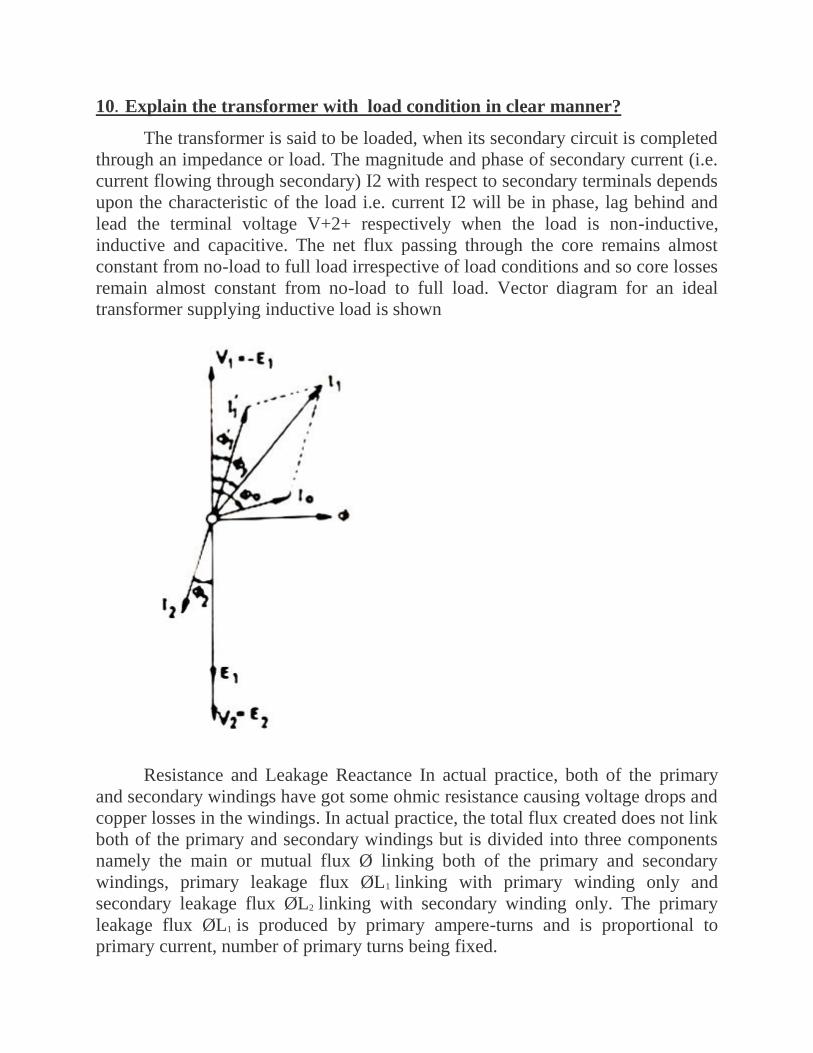
10. Explain the transformer with load condition in clear manner?
The transformer is said to be loaded, when its secondary circuit is completed
through an impedance or load. The magnitude and phase of secondary current (i.e.
current flowing through secondary) I2 with respect to secondary terminals depends
upon the characteristic of the load i.e. current I2 will be in phase, lag behind and
lead the terminal voltage V+2+ respectively when the load is non-inductive,
inductive and capacitive. The net flux passing through the core remains almost
constant from no-load to full load irrespective of load conditions and so core losses
remain almost constant from no-load to full load. Vector diagram for an ideal
transformer supplying inductive load is shown
Resistance and Leakage Reactance In actual practice, both of the primary
and secondary windings have got some ohmic resistance causing voltage drops and
copper losses in the windings. In actual practice, the total flux created does not link
both of the primary and secondary windings but is divided into three components
namely the main or mutual flux Ø linking both of the primary and secondary
windings, primary leakage flux ØL1 linking with primary winding only and
secondary leakage flux ØL2 linking with secondary winding only. The primary
leakage flux ØL1 is produced by primary ampere-turns and is proportional to
primary current, number of primary turns being fixed.

The primary leakage flux ØL1 is in phase with I1 and produces self induced
emf ØL1 is in phase with I1 and produces self induced emf EL1 given as 2f L1 I1 in
the primary winding.
The self induced emf divided by the primary current gives the reactance of
primary and is denoted by X1.
X1 = EL1/I1 = 2πfL1I1/I1 = 2FL1,
leakage reactance of secondary X2 = EL2/E2 = 2fπL2I2/I2 = 2πfL2
Equivalent Resistance and Reactance. The equivalent resistances and
reactance’s of transformer windings referred to primary and secondary sides are
given as below Referred to primary side Equivalent resistance,
Equivalent resistance, = X'1 = Referred to secondary side Equivalent resistance,
Equivalent resistance, = X2 + K2X1 Where K is the transformation ratio.

UNIT III UTILIZATION OF ELECTRICAL POWER
PART A
1. What are the mechanisms for producing forces from wind?
There are two primary mechanism for producing forces from the winds. They are
i. Lift force, and
ii. Drag force
When life force
2. Define Airfoil
Lift forces are produced by changing the velocity of the air stream flowing over
either side of the lifting surface. Speeding up the air flow causes the pressure to
drop, while slowing the air stream down leads to increase in pressure.
This pressure difference produces a force that begins to act on the high pressure
side and moves towards the low pressure side of the lifting surface which is called
an airfoil.
3. Define Magnus Effect
Magnus Effect, caused by spinning a cylinder in an air stream at a high-speed of
rotation. The spinnings slows down the air speed on the side where the cylinder is
moving into wind and increases it on the other side; the result is similar to an
airfoil. This principle has been put to practical use in one or two cases but is not
generally employed.
4. Define Stalling.
When lift decreases and the drag increases quite substantially; this phenomenon is
known as Stalling. For efficient operation, a wind turbine blade needs to function
with as much lift and as little drag as possible because drag dissipates energy.
5. What is the function of back-up in small producers?
For small producers, back-up can take the form of
(1) Battery storage

(2) Connection with the local electricity distribution systems, or
(3) A stand by generator powered by liquid or gaseous fuels
Drag force
6. Define Power Co-efficient.
The fraction of the free-flow wind power that can be ectracted by a rotor is a called
the power co-efficient. Thus
Power Coefficient = Power of wind rotor / Power available in the wind
Where, power available is calculated from the air density, rotor diameter and free
wind speed as discussed earlier. The maximum theoretical power coefficient is
equal to 16/27 or 0.593. This value cannot be exceeded by a rotor in free-flow
wind-stream.
7. Why utilization of wind is considered as part of solar technology?
The major forcing function causing surface winds from the poles toward the
equator is convective circulation. Solar radiation heats the air near the equator, and
this low density heated air is buoyed up. At the surface it is displaced by cooler
more dense higher pressure air flowing from the poles. In the upper atmosphere
near the equator the air thus tends to low back toward the poles and away from the
equator. The net result is a global convective with surface winds from north to
south in the northan hemisphere.
It is clear from the above over simplified model that the wind is basically caused
by the Solar Energy irradiating the Earth. This is why wind utilization is
considered part solar technology.
8. Define Wind.
Wind results from air motion. Air in motion arises from a pressure gradient. The
circulation of air in the atmosphere is caused by the non-uniform heating of the
earth’s surface by the Sun.
9. What are the different types of forces acting on propeller type wind turbine.
There are two types of forces which are acting on the blades. They are
(1) Circumferential force acting in the direction of wheel rotation that provides the
torque, and

(2) Axial force acting in the wind stream that provides an axial thrust that must be
countered by proper mechanical design.
10. What are the different types of vertical axis wind turbines.
i. Savonius Rotor type machines
ii. Darrieus type machines
PART B
1.Write short notes about Wind Power?
All renewable energy (except tidal and geothermal power), ultimately comes
from the sun. The earth receives 1.74x10¹⁷ watts of power (per hour) from the sun.
About one or 2 percent of this energy is converted to wind energy (which is about
50-100 times) more than the energy converted to biomass by all plants on earth.
Differential heating of the earth’s surface and atmosphere induces vertical and
horizontal air currents that are affected by the earth’s rotation and contours of the
land - > WIND. E.g.: Land Sea Breeze Cycle. Winds are influenced by the ground
surface at altitudes up to 100 meters. Wind is slowed by the surface roughness and
obstacles.
When dealing with wind energy, we are concerned with surface winds. A wind
turbine obtains it power input by converting the force o the wind into a torque
(turning force) acting on the rotor blades. The amount of energy which the wind
transfers to the rotor depends on the density of the air, the rotor area, and the wind
speed.
The kinetic energy of a moving body is proportional to its mass (or weight). The
kinetic energy in the wind thus depends on the density of the air, i.e. its mass per
unit of volume. In other words, the “heavier” the air, the more energy is received
by the turbine at 15oC air weight about 1.225 kg per cubic meter, but the density
decrease slightly with increasing humidity.
A typical 600 kW wind turbine has a rotor diameter of 43-44 meters, i.e., a rotor
area of some 1,500 square meters. Fig 5.1 shows the power generated by the wind
mill with respect to the height.
The rotor area determines how much energy a wind turbine is able to harvest from
the wind. Since the rotor area increases with the square of the rotor diameter, a
tubine which is twice as large will receive 22=2x2 = Four times as much energy.

To be considered a good location for wind energy, an area needs to have average
annual wind speeds of at least 12 miles per hour.
They have traditionally been measured at a standard height of ten meters where
they are found to be 20-25% greater than close to the surface. At a height of 60
metre they may be 30-60% higher because of the reduction in the drag effect of the
earth surface.
2.Write short notes about the Wind Power calculation?
Calculation of Power in the Wind
The power in the wind can be computed by using of Kinetics (Kinetic means
relating to or resulting from motion). The wind mill works on the principle of
converting Kinetic energy of the wind to mechanical energy.
We know that power is equal to energy per unit time. The energy available is the
kinetic energy of the wind. The kinetic energy of any particle is equal to one half
its mass times the square of its velocity.
Kinetic Energy of particle = ½ mv2
Where
M : Mass of particle (kg)
V : Velocity of particle (m/s)
The amount of air passing in unit time, through an area ‘A’, with velocity ‘V’ is A
x V, and its mass ‘m’ is equal to its volume multiplied by its density ‘ρ’ of air.
m = ρ AV
Where, m is the mass of air transversing the area ‘A’ swept by the rotating blades
of a wind mill type generator.
Power Coefficient The fraction of the free-flow wind power that can be extracted by the rotor is called
the power co-efficient; Thus,
Power Coefficient = Power of wind rotor / Power available in the wind
Where, power available is calculated from the air density, rotor diameter and free
wind speed as discussed earlier. The maximum theoretical power coefficient is

equal to 16/27 or 0.593. This value cannot be exceeded by a rotor in free-flow
wind-stream.
An ideal rotor, with propeller-type blades of proper aerodynamic design, would
have a power co-efficient approaching 0.59. But such a rotor would not be strong
enough to withstand the stresses to which it is subjected when rotating at a high
rate in a high-speed wind stream.
3.Write short notes about the circuit breakers?
Braking is very frequent in electric drives to stop a motor in a reasonably
short time.
1) Reliable and quick in its action.
2) The braking force must be capable of being controlled.
3) Adequate means be provided for dissipating the stored energy that is kinetic
energy of the rotating parts.
4) In case of a fault in any part of the braking system the whole system must
come to instantaneous rest or result in the application of the brakes.
There are two types of braking:
1) Mechanical braking:
The motor in this case is stopped due to friction between the moving part of
the motor and the brake shoe that is stored energy is dissipated as heat by a brake
shoe or brake lining which rubs against a brake shoe or brake lining which rubs
against a brake drum.
2) Electric braking:
the kinetic energy of the moving parts that is motor is converted into
electrical energy which is consumed in a resistance as heat or alternatively it is
returned to the supply source. During braking operation a motor has to function as
a generator.The motor can be held at stand still. In other words the electric braking
cannot hold the motor at rest. Thus it becomes essential to provide mechanical
brakes in addition to electric braking.
Electric braking:

Various types of electrical braking are:
a) Plugging
b) Rheostatic braking
c) Regenerative braking
4.Write short notes about the illumination in detailed manner?
Luminous intensity
Luminous intensity is an expression of the amount of light power emanating
from a point source within a solid angle of one steradian.
Laws of illumination:
The original standard of light was Wax Candle, which is highly unreliable. It was replaced by a Vaporized Pentane Lamp. This is equal to10 original Candles. In the year 1909, Incandescent Lamp was taken as standard by comparison with a Pentane Lamp. Thing to be kept in mind is Primary Standard should be reproducible.It was in1948, Luminous Intensity; based on Luminance (objective brightness) of a small aperture due to Light from a Radiator maintained at1773°c i.e. Solidification temperature of platinum was adopted as Standard. It consists of:
1. Radiator – Fused Thoria – Thorium Oxide. 45mm long internal dia of 2.5mm. Packed with Fused Thoria Powder at the bottom.
2. Supported Vertically Pure Platinum in a Fused thoria crucible with a small aperture of 1.5mm in a large refractory container.
3. Platinum melted by a High Frequency Eddy current.Luminance = 589000 Candles /m2 ≈600 000 units.
Transparent (Law of Inverse Squares):
Common unit of light intensity is candela. It is Luminous intensity in the Perpendicular direction of a surface, 1 / 600,000 of a black body at temperature of solidification or Freezing of Platinum under Standard Atmospheric pressure. It is abbreviated as Cd. It is indicative of Light Radiating Capacity of a source of Lamp.
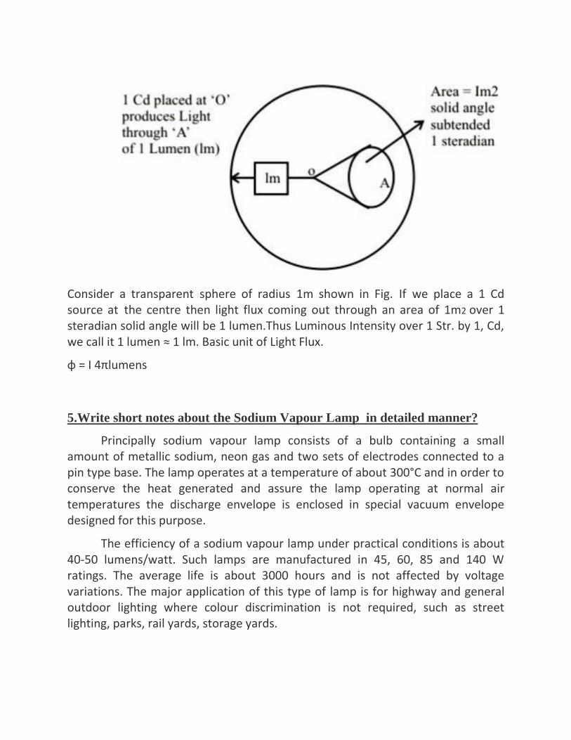
Consider a transparent sphere of radius 1m shown in Fig. If we place a 1 Cd source at the centre then light flux coming out through an area of 1m2 over 1 steradian solid angle will be 1 lumen.Thus Luminous Intensity over 1 Str. by 1, Cd, we call it 1 lumen ≈ 1 lm. Basic unit of Light Flux.
φ = I 4πlumens
5.Write short notes about the Sodium Vapour Lamp in detailed manner?
Principally sodium vapour lamp consists of a bulb containing a small amount of metallic sodium, neon gas and two sets of electrodes connected to a pin type base. The lamp operates at a temperature of about 300°C and in order to conserve the heat generated and assure the lamp operating at normal air temperatures the discharge envelope is enclosed in special vacuum envelope designed for this purpose.
The efficiency of a sodium vapour lamp under practical conditions is about 40-50 lumens/watt. Such lamps are manufactured in 45, 60, 85 and 140 W ratings. The average life is about 3000 hours and is not affected by voltage variations. The major application of this type of lamp is for highway and general outdoor lighting where colour discrimination is not required, such as street lighting, parks, rail yards, storage yards.

6.Write short notes about the fluorescent Lamp in detailed manner?
Employs transformation of UV radiation due to low pressure mercury vapor.
Luminescent Powder in tubular vapor Lamps Enhances brilliancy of
light.Radiation from Low Pressure Mercury Vapor (which is in UV region) is
impinged on Luminescent Materials and re – radiated at longer wavelengths of
visible spectrum. In a Glass Tube small drop of Mercury and small amount of
Argon gas are placed for initiation of discharge. Pressure, voltage and current are
so adjusted that 253.7 nm line is excited. This re-radiates at longer wavelength.
Typically a 40W lamp requires 2-3g of phosphors. Maximum sensitivity is around
250 – 260 nm. Various types of Fluorescent Lamps are:
1. Day Light Fluorescent Lamps- Average Noon Day Light. 6500°k suitable
where demands are not exacting
2. Standard white Light - 3500°k general Lighting.
3. 4500°k white Lamp – between std. white Light & Day Light Lamp.
4. Soft white Lamp – Pinker Light. 25% lower light output than Std. white Lamp suitable for Residential lighting and Restaurants.
Dimension and Voltage depend on Luminous Efficacy, Brightness, Lumen Output and Lumen Maintenance. Reliable Starting is achieved by having preheated cathodes / hot cathode. Half the open circuit voltage should be used by the Lamp and the other half by the ballast. Lamp Voltage decides the arc

length, bulb diameter and lamp current. Hot Cathode lamps operate at lower
voltage < cold Cathode lamps. Typically cold cathodes have 70-100V drop at the
cathode.
7.Write short notes about the mercury vapour Lamp in detailed manner?
High Pressure Mercury Vapour Lamp:
The mercury vapour lamp in construction is similar to sodium vapour lamp.
It gives greenish blue colour light, which causes colour distortion. The efficiency is
about 30-40 lumens per watt.
These lamps (MA type) are manufactured in 250 and 400 W ratings for use
on 200-250 Vac supply. Lamps of this type are used for general industrial lighting,
railway yards, ports, work areas; shopping centers etc where greenish-blue colour
ligh is not objectionable.
Another type, which is manufactured in 300 and 500 W ratings for use on ac
as well as dc supply mains is MAT type. This is similar to MA type except that it
does not use choke as ballast.
Lower wattage lamps, such as 80 and 125 W, are manufactured in a different
design and using high vapour pressure of about 5-10 atmospheres. These are
known as MB type lamps.

8.Write short notes about the charge and discharge characteristics of LI ION
in detailed manner?
nickel and cobalt have been replaced by cobalt has been replaced by nickel
and manganese right, and here it is only manganese and this is of course, is a
different, the same structure the M n 2 O 4, the M n 2 O 4 will have a spinal
structure, but this is also a same structure ok, so these are some of the layers. Next
oxides and here this is the characteristics charge, charge discharge characteristics
of the particular compound, which is spinal structure lethain lithium manganese 4,
manganese 4 spinal structural, we have seen earlier.
This is the charging characteristics of that, and these are the discharge
characteristics under different conditions of discharging, now discharging is done
normally, done at a rate of designated like C by 2 or C by 5 or 20 C the charge rate
or discharge rate, the charge rate is denoted as C or C rate, and signifies a charge or
discharge rate, charge or discharge rate equal to the capacity of the battery in in 1
hour
the capacity of a battery is normally given as ampere hour, that is the total
amount of energy which it can accommodate. So, if you have a capacity of a
particular batteries 1.6 ampere hour, the C 1 C it becomes 1.6 ampere, that means
in 1 hour, 1 hour you charge it fully, or of discharge it fully at the rate of 1.6 amp.
So, if you draw current of 1.6 ampere over a period of 1 hour, then this is the total
capacity of the battery, and this becomes then the C, a charge rate of C by 2 means
actually 0.8 ampere, 0.8 ampere, half of 1.6 will be needed for 2 hours, and a
charge rate of 2 C that means the double the value of the capacity, we have to
charge 3.2 ampere would need 30 minutes half a minute to fully charged. So, it is
basically there rate at which the current is being drawn from the, from the battery
or it is being introduced the charges, introduced battery or to recharge the battery,
so that is what is known as C rate, it assumes that the battery of course, whenever
we are doing it assumed the battery is 100 percent efficient at absorbing the charge,
and can support the pled rate that means, if you charges it at a very fast rate. For
example, 2 C or 10 C, 20 C that means your charging or discharging at a very fast
rate, and the kinetics may not support it. So, the there may be a breakdown of the
structure, this can be done in fact, that is one of the criteria when it battery is
tested.
charging is done at C by 2 rate, half the total capacity, and discharging has
been tried out, discharge have been tried out at C by 5 and in this increasing 20 C,
20 times the overall the capacity of the battery, and even then one can although the
voltage will drop obviously, and charging rate increase, and then you can get a
fairly high a specific charges. So, M n O 4, so L i M n O 4 an alternative cathode

material replacing L i C O 2, so these are the some of the typical experimental
data, and which is been taken from literature of course, and the these are the
possibilities, so one can charge it was very fast rate, as well as discharge fairly at a
very fast rate.
9.Write short notes about the domestic refrigerator in detailed manner?
refrigeration is the cooling of air/liquids, thus providing lower temperatures
to preserve food, cool beverages, make ice and for many other applications.
refrigeration is the process of removing heat from a place where it is not
wanted and transferring that heat to a place where it makes little difference.
In the average household, the room temperature from summer to winter is
normally between 700F and 900F.
The temperature inside the refrigerator fresh food section should be about
350F
The rating of a refrigeration machine is obtained by refrigerating effect or
the amount of heat extracted in a given time from a body or space.
One tonne of refrigeration is defined as the refrigerating effect (amount of
heat extracted ) produced by melting 1 tonne of ice from and at 00C in 24 hours.
We know that latent heat of fusion of ice = 336 kJ/kg.
Refrigerating effect of this heat in terms of tonne in 24 hours is rated as
tonne of refrigeration
1T.R = 336x 1000/ 24 = 14000kJ/hr.
= 210kJ/min. = 3.85 kJ/se
Performance of the refrigerator is determined by using co-efficient of
performance which is defined as requiredinput. In desired output from the
conservation of energy principle.

10.Write short notes about the earthing system in detailed manner?
Need of Earthing or Grounding. The primary purpose of earthing is to avoid or minimize the danger of
electrocution, fire due to earth leakage of current through undesired path and to
ensure that the potential of a current carrying conductor does not rise with respect
to the earth than its designed insulation.
When the metallic part of electrical appliances (parts that can conduct or
allow passage of electric current) comes in contact with a live wire, maybe due to
failure of installations or metal become charged and static charge accumulates on
it. To avoid such instances, the power supply systems and parts of appliances have
to be earthed so as to transfer the charge directly to the earth.
Below are the basic needs of Earthing.
To protect human lives as well as provide safety to electrical devices and
appliances from leakage current.
To keep voltage as constant in the healthy phase (If fault occurs on any one
phase).
To Protect Electric system and buildings form lighting.
To serve as a return conductor in electric traction system and communication.
To avoid the risk of fire in electrical installation systems.
Different Terms used in Electrical Earthing Earth: The proper connection between electrical installation systems via
conductor to the buried plate in the earth is known as Earth.
Earthed: When an electrical device, appliance or wiring system connected to the
earth through earth electrode, it is known as earthed device or simple “Earthed”.
Solidly Earthed: When an electric device, appliance or electrical installation is
connected to the earth electrode without a fuse, circuit breaker or
resistance/Impedance, It is called “solidly earthed”.
Earth Electrode: When a conductor (or conductive plate) buried in the earth for
electrical earthing system. It is known to be Earth Electrode. Earth electrodes are
in different shapes like, conductive plate, conductive rod, metal water pipe or
any other conductor with low resistance.
Earthing Lead: The conductor wire or conductive strip connected between
Earth electrode and Electrical installation system and devices in called Earthing
lead.
Earth Continuity Conductor: The conductor wire, which is connected among
different electrical devices and appliances like, distribution board, different plugs
and appliances etc. in other words, the wire between earthing lead and electrical
device or appliance is called earth continuity conductor. It may be in the shape of
metal pipe (fully or partial), or cable metallic sheath or flexible wire.

Sub Main Earthing Conductor: A wire connected between switch board and
distribution board i.e. that conductor is related to sub main circuits.
Earth Resistance: This is the total resistance between earth electrode and earth
in Ω (Ohms). Earth resistance is the algebraic sum of the resistances of earth
continuity conductor, earthing lead, earth electrode and earth.
points to be earthed Earthing is not done anyhow. According to IE rules and IEE (Institute of
Electrical Engineers) regulations,
Earth pin of 3-pin lighting plug sockets and 4-pin power plug should be
efficiently and permanently earthed.
All metal casing or metallic coverings containing or protecting any electric
supply line or apparatus such as GI pipes and conduits enclosing VIR or PVC
cables, iron clad switches, iron clad distribution fuse boards etc should be
earthed (connected to earth).
The frame of every generator, stationary motors and metallic parts of all
transformers used for controlling energy should be earthed by two separate and
yet distinct connections with the earth.
In a dc 3-wire system, the middle conductors should be earthed at the generating
station.
Stay wires that are for overhead lines should be connected to earth by connecting
at least one strand to the earth wires.

UNIT IV ELECTRONIC CIRCUITS
PART A
1. What is meant by Q-factor?
Q-factor is known as the quality factor. It is used to measure the quality
factor of the coils such as inductors, Capacitors etc.
2. Define transistor action.
A transistor consists of 2 coupled PN junctions. The base is a common
region to both junctions and makes a coupling between them. Since the base
regions are smaller, a significant interaction between junctions will be available.
This is called transistor actions.
3. Define hybrid parameters.
Any linear circuit having input and output terminals can be analysed by four
parameters(one measured on ohm, one in mho and two dimensionless) called
hybrid or hparameters.
4. Which is the most commonly used transistor configuration? Why?
The CE Configuration is most commonly used. The reasons are
High Current gain
High voltage gain
High power gain
Moderate input to output ratio.
5. What are the types of transistors?
Unipolar junction transistor
Bipolar junction transistor.
6. Define delay time
It is defined as the time required for the current to rise from 0 to 10% of its
maximum value.

7. Define rise time
It is the time required for the current to rise from 0 to 90 percentage of the
maximum value.
8. Define Biasing
“Biasing” is providing minimum external voltage and current to activate the
device to study its characteristics.
There are two operating regions and two "biasing" conditions for the standard
Junction Diode and they are:
1. Zero Bias 2.Forward Bias 3.Reverse Bias
9. What is meant by zener effect?
When the doping is heavy, even the reverse voltage is low, the electric field at
barrier will be so strong thus the electrons in the covalent bonds can break away
from the bonds. This effect is known asZener effect.
10.Draw thw V/I characteristics of PN diode?

PART B
1.Explain the V/I characteristics of ZENER diode?
Zener Diode
A diode which exhibits the zener effect is called a Zener Diode. Hence it is
defined as a reverse biased heavily doped PN junction diode which operates in
breakdown region.
zener effect
In a general purpose PN diode the doping is light; as a result of this the
breakdown voltage is high. If a P and N region are heavily doped then the
breakdown voltage can be reduced. When the doping is heavy, even the reverse
voltage is low, the electric field at barrier will be so strong thus the electrons in the
covalent bonds can break away from the bonds. This effect is known asZener
effect.
ZENER DIODE
A diode which exhibits the zener effect is called a Zener Diode.
Hence it is defined as a reverse biased heavily doped PN junction diode
which operates in breakdown region. The zener diodes have been designed
to operate at voltages ranging from a few volts to several hundred
volts.Zener Breakdown occurs in junctions which is heavily doped and
have narrow depletion layers. The breakdown voltage sets up a very strong
electric field. This field is so strong enough to break or rupture the covalent
bonds thereby generating electron hole pairs.Even a small reverse voltage is
capable of producing large number of current carrier. When a zener diode is
operated in the breakdown region care must be taken to see that the power
dissipation across the junction is within the power rating of the diode
otherwise heavy current flowing through the diode may destroy it.
V-I characteristics of Zener diode

The illustration above shows this phenomenon in a current vs voltage graph
with a zener diode connected in the forward direction .It behaves exactly as a
standarddiode. In the reverse direction however there is a very small leakage
current between 0v and the zener voltage –i.e. just a tiny amount of current is
able to flow.Then, when the voltage reaches the breakdown voltage (vz),suddenly
current can flow freely through it.
Application of Zener diode
a) as voltage regulator
b) as peak clippers
c) for reshaping waveforms
2. Briefly describe the operation of Half wave Rectifier?
Principle
It is a circuit that converts alternating voltage or current into pulsating
voltage or current for half the period of input cycle hence it is named as “half
wave rectifier”

Operation
During the positive half cycle of input, the diode D is forward biased, it offers
very small resistance and it acts as closed switch and hence conducts the
current through the load resistor.
During the negative half cycle of the input diode D is heavily reverse biased,
it offers very high resistance and it acts as open switch hence it does not
conduct any current. The rectified output voltage will be in phase with AC
input voltage for completely resistive load.

Construction
It consists of step-down transformer, semiconductor diode and the load
resistance.
The step-down transformer – reduce the available ac voltage into required
level of smaller ac voltage.
The diode can be used to convert the ac into pulsating dc.
3. Briefly describe the operation of Full wave Rectifier?
Principle
A circuit that converts the ac voltage or current into pulsating voltage or current
during both half cycle of input is known as “full wave rectifier”.
Operation
During positive half cycle of ac input, diode D1 becomes forward
biased, provides very small resistance and acts as closed switch,
resulting in the flow of current.
During negative half cycle, diode D1 reverse biased, offers high
resistance and it acts as open circuit.
The “rectifier” is a circuit that converts AC voltages and currents into
pulsating DC voltages and currents. It consists of DC components and the
unwanted ac ripple or harmonic components which can be removed by using filter
circuit. Thus the output obtained will be steady DC voltage and magnitude of DC
voltage can be varied by varying the magnitude of AC voltage.
Filters: A circuit that removes ripples (unwanted ac components) present in
the pulsating dc voltage.
Regulator: A circuit that maintains the terminal voltage as constant even if
the input voltage or load current varying.

4. Explain the operation of BIPOLAR JUNCTION TRANSISTOR?
A bipolar junction transistor is a three terminal semiconductor device in
which the operation depends on the interaction of majority and minority
carriers.Transistor refers to Transfer Resistor i.e., signals are transferred from low
resistance circuit into high resistance circuit.BJT consists of silicon crystal in
which a layer of ‘N’ type silicon is sandwiched between two layers of ‘P’ type
silicon. The semiconductor sandwiched is extremely smaller in size.In other words,
it consists of two back to back PN junction joined together to form single piece of
semiconductor crystal. These two junctions gives three region called Emitter, Base
and Collector.
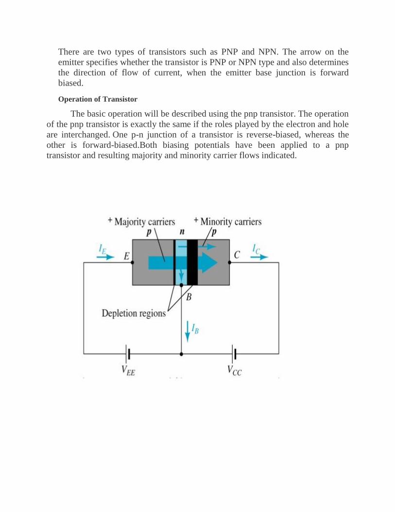
There are two types of transistors such as PNP and NPN. The arrow on the
emitter specifies whether the transistor is PNP or NPN type and also determines
the direction of flow of current, when the emitter base junction is forward
biased.
Operation of Transistor
The basic operation will be described using the pnp transistor. The operation
of the pnp transistor is exactly the same if the roles played by the electron and hole
are interchanged. One p-n junction of a transistor is reverse-biased, whereas the
other is forward-biased.Both biasing potentials have been applied to a pnp
transistor and resulting majority and minority carrier flows indicated.

Majority carriers (+) will diffuse across the forward-biased p-n junction into the
n-type material.A very small number of carriers (+) will through n-type material
to the base terminal. Resulting IB is typically in order of microamperes. The
large number of majority carriers will diffuse across the reverse-biased junction
into the p-type material connected to the collector terminal.Majority carriers can
cross the reverse-biased junction because the injected majority carriers will
appear as minority carriers in the n-type material.
Applying KCL to the transistor :
IE = IC + IB
The comprises of two components – the majority and minority carriers
IC = ICmajority + ICOminority
ICO – IC current with emitter terminal open and is called leakage current.
5.Describe the Common Base configuration of transistor?
Common-base terminology is derived from the fact that the :
base is common to both input and output of the configuration.
base is usually the terminal closest to or at ground potential.
All current directions will refer to conventional (hole) flow and the arrows in
all electronic symbols have a direction defined by this convention.
Note that the applied biasing (voltage sources) are such as to establish current
in the direction indicated for each branch.
To describe the behavior of common-base amplifiers requires two set of
characteristics:
1.Input or driving point characteristics.
2.Output or collector characteristics
The output characteristics has 3 basic regions:
1.Active region –defined by the biasing arrangements
2.Cutoff region – region where the collector current is 0A
3.Saturation region- region of the characteristics to the left of
VCB = 0V


The curves (output characteristics) clearly indicate that a first approximation to the
relationship between IE and IC in the active region is given by
IC ≈IE
Once a transistor is in the ‘on’ state, the base-emitter voltage will be assumed
to be
VBE = 0.7V

In the dc mode the level of IC and IE due to the majority carriers are related by
a quantity called alpha
α = IC / IE
IC = α IE + ICBO
It can then be summarize to IC = αIE (ignore ICBO due to small value)
For ac situations where the point of operation moves on the characteristics
curve, an ac alpha defined by
Alpha a common base current gain factor that shows the efficiency by
calculating the current percent from current flow from emitter to collector. The
value of is typical from
0.9 ~ 0.998.
6.Describe the Common Emitter configuration of transistor?
It is called common-emitter configuration since :
emitter is common or reference to both input and output terminals.
emitter is usually the terminal closest to or at ground potential.
Almost amplifier design is using connection of CE due to the high gain for
current and voltage.
Two set of characteristics are necessary to describe the behavior for CE;
input (base terminal) and output (collector terminal) parameters.
Input characteristics for CE configuration
IB in microamperes compared to milliamperes of IC.
IB will flow when VBE > 0.7V for silicon and 0.3V for germanium
Before this value IB is very small and no IB.
Base-emitter junction is forward bias
Increasing VCE will reduce IB for different values.


Output characteristics for CE configuration
For small VCE (VCE < VCESAT, IC increase linearly with increasing of VCE
VCE > VCESAT IC not totally depends on VCE -- > constant IC
IB(uA) is very small compare to IC (mA). Small increase in IB cause big
increase in IC
IB=0 A -- > ICEO occur.
Noticing the value when IC=0A. There is still some value of current flows.

7.Describe the Common Collector configuration of transistor?
Also called emitter-follower (EF).
It is called common-emitter configuration since both the
signal source and the load share the collector terminal as a common
connection point.
The output voltage is obtained at emitter terminal.
The input characteristic of common-collector configuration is similar with
common-emitter. configuration.
Common-collector circuit configuration is provided with the load resistor
connected from emitter to ground.
It is used primarily for impedance-matching purpose since it has high input
impedance and low output impedance.

For the common-collector configuration, the output characteristics are a
plot of IE vs VCE for a range of values of IB.
8. Explain how the Small Signal Amplifier has functioned in clear manner?
When the input signal is so weak as to produce small fluctuations in the
collector current compared to its quiescent value, the amplifier is known as Small
Signal Amplifier.
In other words, as the name indicates, the input applied to the circuit is
Vin << Vth. It has only one amplifying device.
Α = IC / IE
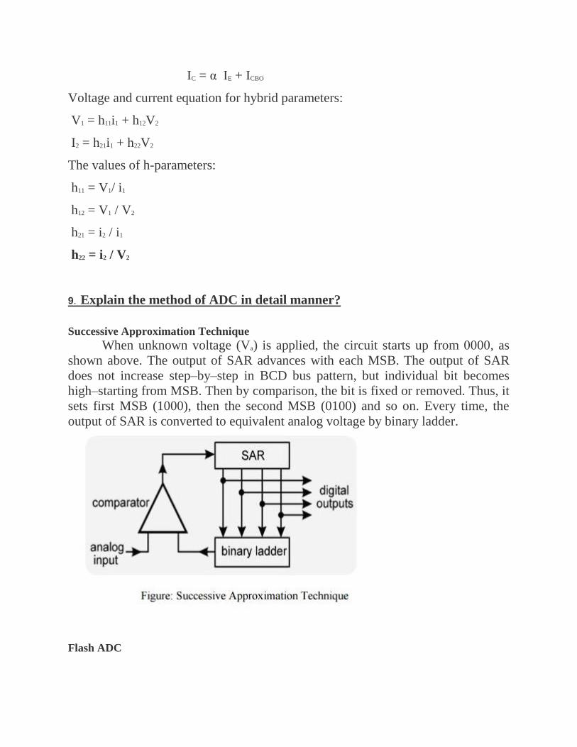
IC = α IE + ICBO
Voltage and current equation for hybrid parameters:
V1 = h11i1 + h12V2
I2 = h21i1 + h22V2
The values of h-parameters:
h11 = V1/ i1
h12 = V1 / V2
h21 = i2 / i1
h22 = i2 / V2
9. Explain the method of ADC in detail manner?
Successive Approximation Technique
When unknown voltage (Va) is applied, the circuit starts up from 0000, as
shown above. The output of SAR advances with each MSB. The output of SAR
does not increase step–by–step in BCD bus pattern, but individual bit becomes
high–starting from MSB. Then by comparison, the bit is fixed or removed. Thus, it
sets first MSB (1000), then the second MSB (0100) and so on. Every time, the
output of SAR is converted to equivalent analog voltage by binary ladder.
Flash ADC
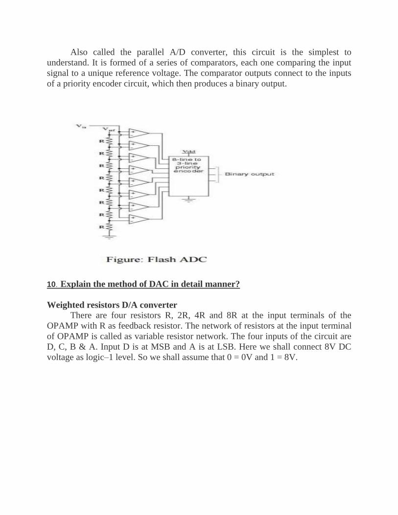
Also called the parallel A/D converter, this circuit is the simplest to
understand. It is formed of a series of comparators, each one comparing the input
signal to a unique reference voltage. The comparator outputs connect to the inputs
of a priority encoder circuit, which then produces a binary output.
10. Explain the method of DAC in detail manner?
Weighted resistors D/A converter There are four resistors R, 2R, 4R and 8R at the input terminals of the
OPAMP with R as feedback resistor. The network of resistors at the input terminal
of OPAMP is called as variable resistor network. The four inputs of the circuit are
D, C, B & A. Input D is at MSB and A is at LSB. Here we shall connect 8V DC
voltage as logic–1 level. So we shall assume that 0 = 0V and 1 = 8V.

Figure: Weighted resistors D/A converter
Now the working of the circuit is as follows. Since the circuit is summing
amplifier, its output is given by the following equation
Working of the circuit
When input DCBA = 0000, then putting these value in above equation (1) we get
When digital input of the circuit DCBA = 0001, then putting these value in above
equation (1) we get
When digital input of the circuit DCBA = 0010, then putting these value in above
equation (1) we get
R–2R Ladder D/A Converter
It is modern type of resistor network. It has only two values of resistors the
R and 2R. These values repeat throughout in the circuit. The OPAMP is used at
output for scaling the output voltage. The working of the circuit can be understood
as follows. For simplicity, we ignore the OPAMP in the above circuit (this is
because its gain is unity). Now consider the circuit, without OPAMP. Suppose the
digital input is DCBA = 1000. Then the circuit is reduced to a small circuit.

Now suppose digital input of the same circuit is changed to DCBA = 0100. Then
the output voltage will be V/4, when DCBA = 0010, output voltage will be V/8, for
DCBA = 0001, output voltage will be V/16 and so on. The general formula for the
above circuit of R–2R ladder, including the OPAMP also, will be –
You can take (R) common from the above formula and simplify it. With the help
of this formula, we can calculate any combination of digital input into its
equivalent analog voltage at the output terminals.
UNIT V ELECTRICAL MEASUREMENTS
PART A
1. What are the basic elements of a generalized measurement system?
Primary sensing element which is generally a transducer. Data conditioning
element which further consists of variable conversion element and variable
manipulation element.
Data transmission and presentation elements which include data transmission
system and data display system.
2. List any four Static characteristics of a measuring system.
Accuracy,
Precision,
Error,
Resolution,
Stability,
Linearity etc.
3. Define the term Accuracy.

The accuracy is defined as the degree of closeness with which the instrument
reading approaches the true value of the quantity to be measured. It indicates the
ability of an instrument to indicate the true value of the quantity.
4. What is an Error?
The algebraic difference between the indicated value and the true value of
the quantity to be measured is called an error.
5. What is calibration?
Calibration is the process of making an adjustment or making a scale so that
the readings of an instrument agree with the accepted value and the certified
standard.
6. Define the term Precision.
It is the Measure of consistency or repeatability of measurements. It denotes
the amount by which the individual readings are departed about the average of
number of readings.
7.Give the applications of measurement systems.
The instruments and measurement systems are sued for
Monitoring of processes and operations.
Control of processes and operations.
Experimental engineering analysis.
8. What are the various Dynamic characteristics?
Various Dynamic characteristics are
Fidelity
Speed of Response
Time Delay
Lag

Dynamic error
9. Explain the function of measurement system.
The measurement system consists of a transducing element which converts
the quantity to be measured in an analogous form. The analogous signal is then
processed by some intermediate means and is then fed to the end device which
presents the results of the measurement.
10. Define static characteristics.
Static characteristics are the set of rules or criteria that is defined for those
instruments that varies very slowly with time or remains a constant.
PART B
1.Explain the Static characteristics of measurement?
The set of criteria defined for the instruments, which are used to measure the quantities which are slowly varying with time or mostly constant, i.e., do not vary with time, is called ‘static characteristics’.
Accuracy:
It is the degree of closeness with which the reading approaches the true value of
the quantity to be measured. The accuracy can be expressed in following ways:
Conformity:
Consider a resistor having true value as 2385692 , which is being measured by an ohmmeter. But the reader can read consistently, a value as 2.4 M due to the non availability of proper scale. The error created due to the limitation of the scale reading is a precision error.
Number of significant figures:
The precision of the measurement is obtained from the number of significant figures, in which the reading is expressed. The significant figures convey the

actual information about the magnitude & the measurement precision of the quantity. The precision can be mathematically expressed as:
Where, P = precision
Xn = Value of nth measurement
Xn = Average value the set of measurement values
Sensitivity:
The sensitivity denotes the smallest change in the measured variable to which the instrument responds. It is defined as the ratio of the changes in the output of an instrument to a change in the value of the quantity to be measured.
Reproducibility:
It is the degree of closeness with which a given value may be repeatedly measured. It is specified in terms of scale readings over a given period of time.
Repeatability:
It is defined as the variation of scale reading & random in nature Drift: Drift may be classified into three categories:
a) zero drift:
If the whole calibration gradually shifts due to slippage, permanent set, or due to undue warming up of electronic tube circuits, zero drift sets in.

b) Span drift or sensitivity drift
If there is proportional change in the indication all along the upward scale, the drifts is called span drift or sensitivity drift.
c) Zonal drift:
In case the drift occurs only a portion of span of an instrument, it is called zonal drift.
Resolution:
If the input is slowly increased from some arbitrary input value, it will again be found that output does not change at all until a certain increment is exceeded. This increment is called resolution.
Threshold:
If the instrument input is increased very gradually from zero there will be some minimum value below which no output change can be detected. This minimum value defines the threshold of the instrument.
Stability:
It is the ability of an instrument to retain its performance throughout is specified operating life.
Tolerance:

The maximum allowable error in the measurement is specified in terms of some value which is called tolerance.
Range or span:
The minimum & maximum values of a quantity for which an instrument is designed to measure is called its range or span.
2.Explain the Dynamic characteristics of measurement?
The set of criteria defined for the instruments, which are changes rapidly with time,
is called ‘dynamic characteristics’.
The various static characteristics are:
Speed of response
Measuring lag
Fidelity
Dynamic error
Speed of response:
It is defined as the rapidity with which a measurement system responds to changes
in the measured quantity.
Measuring lag:
It is the retardation or delay in the response of a measurement system to changes in
the measured quantity. The measuring lags are of two types:
a) Retardation type:
In this case the response of the measurement system begins immediately after the
change in measured quantity has occurred.
b) Time delay lag:
In this case the response of the measurement system begins after a dead time after
the application of the input. Fidelity: It is defined as the degree to which a

measurement system indicates changes in the measurand quantity without dynamic
error.
3.Explain the types of measurement errors in detailed manner?
Errors in Measurement
1.Theoretical errors:
The explicit or implicit model on which we base our interpretation of our
measurements may be inapplicable or inaccurate.Range of Validity: A model is
applicable only within a limited range of Conditions.Be-yond that, it will give
inaccurate predictions.Approximation: Models have finite precision even within
their range of validity
2.Static errors:
i. Parallax: Analog meters use a needle as a pointer to indicate the measured
value. Reading this at an oblique angle causes a misreading, known as a parallax
reading error.
ii. Interpolation: The needle often rests between two calibrated marks.
Guessing its position by interpolation is subject to an error that depends on the
size of the scale, and on the visual acuity and experience of the person reading the
meter.
iii. Last-digit bobble: Digital readouts re often observed to oscillate between two neighboring values, for example a digital voltmeter (DVM) may alternately show 3.455 and 3.456 volts. This occurs when the actual value is about midway between the two displayed values. Small variations in the system under test, or in the meter itself, are sufficient to change the reading when it is delicately poised between the two values.
3.Environmental errors:
Measurements can be affected by change in ambient factors
I. Temperature
II. Pressure
III. Electromagnetic field: Static electric or magnetic f i e l d s , dynamic
(changing) fields, and propagating fields (radiation) can interfere with
measurements.

4. Characteristic errors:
Zero Offset: a meter (for example) may read zero when the actual value is
nonzero. This is a common form of calibration error.
Gain error: amplifiers are widely used in instruments such as CRO probes, and we
may trust that “times 10” means precisely what it says only when the
amplification has been carefully calibrated.
Processing error: modern instruments contain complex processing devices such as
analog computers which can introduce errors into the process leading to
thedisplayed value of a measurement.
Repeatability error: instruments change over time, which is why they must be
regularly calibrated, just as a car must be serviced. Instruments change, however
slightly, even between consecutive measurements.
Nonlinearity: Drive an amplifier to too high a gain and it will operate in its
nonlinear regions, producing a severely distorted output signal.
Resolution: devices can only resolve (that is, distinguish) values that are
sufficiently separated .For example, optical instruments cannot easily resolve
objects less than one wavelength apart.
5.Drift:
Drift is a complex phenomenon for which the observed effects are that the
sensitivity and offset values vary. It also can alter the accuracy of the instrument
differently at the various amplitudes of the signal present.
4.Describe the working principle of strain gauges in detailed manner?
Principle of Working of Strain Gauges
When force is applied to any metallic wire its length increases due to the
strain. The more is the applied force, more is the strain and more is the increase in
length of the wire. If L 1 is the initial length of the wire and L2 is the final length
after application of the force, the strain is given as: ε = (L2-L1)/L1 Further, as the
length of the stretched wire increases, its diameter decreases

Now, we know that resistance of the conductor is the inverse function of the
length. As the length of the conductor increases its resistance decreases. This
change in resistance of the conductor can be measured easily and calibrated against
the applied force. Thus strain gauges can be used to measure force and related
parameters like displacement and stress. The input and output relationship of the
strain gauges can be expressed by the term gauge factor or gauge gradient, which is
defined as the change in resistance R for the given value of applied strain ε.
Applications of the Strain Gauges
1) Measurement of strain
2) Measurement of other quantities
5.Describe the working principle of LVDT in detailed manner?
LVDT (Linear Variable Differential Transformer) The LVDT operation does not require electrical contact between the moving
part (probe or core rod assembly) and the transformer, but rather relies on
electromagnetic coupling; this and the fact that they operate without any built-in
electronic circuitry are the primary reasons why LVDTs have been widely used in

applications where long life and high reliability under severe environments are a
required, such Military/Aerospace applications.
The LVDT consists of a primary coil (of magnet wire) wound over the
whole length of a non-ferromagnetic bore liner (or spool tube) or a cylindrical coil
form. Two secondary coils are wound on top of the primary coil for “long stroke”
LVDTs (i.e. for actuator main RAM) or each side of the primary coil for “Short
stroke” LVDTs (i.e. for electro-hydraulic servo-valve or EHSV). The two
secondary windings are typically connected in “opposite series” (or wound in
opposite rotational directions). A ferromagnetic core, which length is a fraction of
the bore liner length, magnetically couples the primary to the secondary winding
turns that are located above the length of the core.
When the primary coil is excited with a sine wave voltage (Vin), it generate a
variable magnetic field which, concentrated by the core, induces the secondary

voltages (also sine waves). While the secondary windings are designed so that the
differential output voltage (Va-Vb) is proportional to the core position from null,
the phase angle (close to 0 degree or close to 180 degrees depending of direction)
determines the direction away from the mechanical zero. The zero is defined as the
core position where the phase angle of the (Va-Vb) differential output is 90
degrees.
The differential output between the two secondary outputs (Va-Vb) when
the core is at the mechanical zero (or “Null Position”) is called the Null Voltage; as
the phase angle at null position is 90 degrees, the Null Voltage is a “quadrature”
voltage. This residual voltage is due to the complex nature of the LVDT electrical
model, which includes the parasitic capacitances of the windings
6.Describe the working principle of RVDT in detailed manner?
Rotary Variable Differential Transformer (RVDT)
Rotary Variable Differential Transformer (RVDT) A Rotary Variable
Differential Transformer (RVDT) is an electromechanical transducer that provides
a variable alternating current (AC) output voltage that is linearly proportional to
the angular displacement of its input shaft.
When energized with a fixed AC source, the output signal is linear within a
specified range over the angular displacement. RVDT’s utilize brushless, non-
contacting technology to ensure long-life and reliable, repeatable position
sensing with infinite resolution. Such reliable and repeatable performance assures
accurate position sensing under the most extreme operating conditions. Moog
offers seven frequency optimized RVDT’s in a basic size 8 configured housing.
Each is designed to operate at a specific frequency. Frequency optimization
provides the benefit of an increased operating range of angular displacement with a
reduction in sensor size and weight.

The Rotational Variable Differential Transformer (RVDT) is used to measure
rotational angles and operates under the same principles as the LVDT sensor.
Whereas the LVDT uses a cylindrical iron core, the RVDT uses a rotary
ferromagnetic core.
7.Describe the working principle of Piezoelectric Transducer
in detailed manner?
The main principle of a piezoelectric transducer is that a force, when applied
on the quartz crystal, produces electric charges on the crystal surface. The charge
thus produced can be called as piezoelectricity. Piezo electricity can be defined as
the electrical polarization produced by mechanical strain on certain class of
crystals. The rate of charge produced will be proportional to the rate of change of
force applied as input. As the charge produced is very small, a charge amplifier is
needed so as to produce an output voltage big enough to be measured. The device
is also known to be mechanically s tiff. For example, if a force of 15 KN is given
to the transducer, it may only deflect to a maximum of 0.002mm. But the output
response may be a s high as 100 KHz. This proves that the device is besst
applicable for dynamic measurement.
Piezoelectric Transducer can me asurepressure in the same way a force or
an acceleration can be measured. For low pressure measurement, possible
vibration of the amount should be compensated for. The pressure measuring quartz
disc stack faces the pressure through a diaphragm and on the other side of this
stack, the comp ensating mass followed by compensating quart z.

Advantages
o Very high frequency response.
o Self generating, so no need of external source.
o Simple to use as they have small dimensions and large measuring
range.
8.Describe the working principle of Energy Meter in detailed manner?
Introduction
The energy meter is an electrical measuring device, which is used to
record Electrical Energy Consumed over a specified period of time in terms of
units.Electric meters are typically calibrated in billing units, the most common one
being the kilowatt hour.
A periodic reading of electric meters establishes billing cycles and energy
used during a cycle.
Features:
* Display of current time (24 hours type), week, load power and cost tariff.
* Display of total on time, total used energy and accrued energy cost.
* Display of total record time, total on time and percentage.
* Dual programmable power tariffs.
* Connection, operation settings.

9.Describe the working principle of moving coil in detailed manner?
Moving Coil
Moving Coil Instruments are used for measuring DC quantities. They can be
used on AC systems when fed through bridge rectifiers. Center magnet system is
incorporated in our moving coil instruments which completely shields the
movement from the effect of external magnetic fields. The movement is pivoted
between synthetic sapphire jewel bearings for frictionless operation.
10.Describe the working principle of moving iron in detailed manner?
Moving Iron
Moving Iron Instruments are generally used for measuring AC Voltage and
Currents. A feature of the moving element is that it is fitted with synthetic
sapphire jewels. The movement is light, quick acting, but extremely robust. An
efficient system of fluid damping is employed. The movement is efficiently
shielded against the effect of external magnetic fields.

