bdm federal, inc. = report to federal, inc. bdm-vas-0784-93-tr 1.0 objective bdm international, inc....
TRANSCRIPT

MASTER COPY KEEP THIS COPY FOR REPRODUCTION PURPOSES
-A0 771oPAE o,,o, 0704-0188
gthertingM and in it ,1 iformtfionll•l sl~ ~lena corme is r ararlgl this burole" estimate or an'y other ase at thliscoIllcionl of inlfc.. . . ..... •,, meeaKquarterServices. Directorate for Itiorrmaton Op~erations anid RepDorts. I as iS jeferon
1. AGENCY USE ONLY (Leave blank) 1 2. REPORT DATE 3. REPORT TYPE AND DATES COVEREDI June 3, 1993 Final Report 26 Nov 90-30 Nov 92
4. TITLE AND SUBTITLE S. FUNDING NUMBERSSmart Materials / Structures Technical Analysis DAAL03-91-C-0002
6. AUTHOR(S)
Dr. Phillip A. ParrishDr. Carlos J. CoeDr. Norman M. Wereley
7. PERFORMING ORGANIZATION NAME(S) AND ADORESS(ES. B' ~ . PERFORMING ORGANIZATIONBDM Federal, Inc. = REPORT NUMBER
4001 North Fairfax Drive _ -D,-VAS-0784-93-TR
Suite 750 . ,Arlington, VA 22203 "...._
9. SPONSORING/ MONITORING AGENCY NAME(S) ANCVOPBESS(ES) ir 10. SPONSORING/ MONITORINGAGENCY REPORT NUMBER
U. S. Army Research Office toP. 0. Box 12211 ARO 28608.1-MSResearch Triangle Park, NC 27709-2211
11. SUPPLEMENTARY NOTES
The view, opinions and/or findings contained in this report are those of theauthor(s) and should not be construed as an official Department of the Armyposition, policy, or decision, unless so designated by other documentation.
12a. DISTRIBUTION/ AVAILABILITY STATEMENT i 12b. DISTRIBUTION fnf-
Approved for public release; distribution unlimited. 93-15719
13. ABSTRACT (Maximum 200 words)
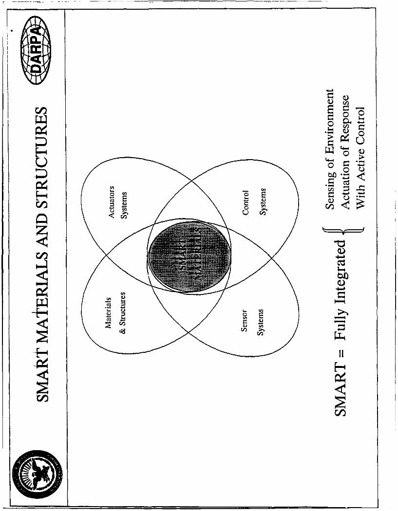
'Smart' Materials and Structures have the capability to respond to their environmentto a significant degree, by virtue of intrinsic properties and/or built-in sensor/actuator systems. The words 'smart' or 'intelligent' as applied to materials/struc-tures are used in an idealistic and imprecise way to indicate an analogy with theintegrated sensor/actuator/control systems evolved by living beings. The programatiobjectives of this proposal suggest the following definition of Smart Materials/Structures (SMS): Smart Materials / Structures (SMS) - Structural systems based uponmaterials with the ability to SENSE their own response to environmental and opera-tional stimuli, and MODIFY that response in such as way as to maintain or optimizestructural performance, utilizing embedded sensors and actuators interfaced withclosed-loop ADAPTIVE CONTROL systems based on system stimulus-response models. Inthis effort, BDM Federal, Inc., a subsidiary of BDM International, Inc. (BDM)conducted a technical analysis of Smart Materials and Structures in order to assistDARPA in planning a future initiative in this area. The ultimate goal of SmartMaterials/Structures is the development of smart subsystems, consisting of materialssensors, actuators, and controllers, etc., capable of significantly improving the
14. SUBJECT TERMS performance or uou systems. IS. NUMBER OF PAGES
4816. PRICE CODE
17. SECURITY CLASSIFICATION I 18. SECURITY CLASSIFICATION 19. SECURITY CLASSIFICATION 20. LIMITATION OF ABSTRACT
OF REPORT OF T4IS PAGE OF ABSTRACT
UNCLASSIFIED I UNCLASSIFIED I UNCLASSIFIED ULNSN 7540-01-280-5500 Standard Form 298 (Rev 2-89)
Pr21 ,1 &I ANS Std 139-19

NOTICE
0-0
THIS DOCUMENT IS BEST
QUALITY AVAILABLE. THE COPY
FURNISHED TO DTIC CONTAINED
A SIGNIFICANT NUMBER OF
PAGES WHICH DO NOT
REPRODUCE LEGIBLY.

SMART MATERIALS / STRUCTURESTECIHNICAL ANALYSIS
FINAL REPORT
Accesion For
NTIS CRA&MDTIC TAB
DR. PHILLIP A. PARRISH UWan ounced o,
DR. CARLOS J. COE J.tifat . ....................
DR. NORMAN M. WERELEY By
Dist. ibution l
Availability Codes
JUNE 3,1993 Avail and/orDist Special
U. S. ARMY RESEARCH OFFICE
ARO PROPOSAL NUMBER: 28608-MSCONTRACT NUMBER: DAAL03-91-C-0002
BDM FEDERAL, INC.4001 NORTH FAIRFAX DRIVE, SUITE 750
ARLINGTON, VA 22203(703) 351-6900
APPROVED FOR PUBLIC RELEASE;DISTRIBUTION UNLIMITED

BDM IFEDERAL, INC. BDM-VAS-0784-93-TR
TABLE OF CONTENTS
1.0 O BJECTIV E ........................................................................................................................ 1
2.0 SMART MATERIALS / STRUCTURES ........................................................................... 1
2.1 INTRODUCTION ........................................................................................................ 1
2.2 THE CURRENT TECHNOLOGY BASE .................................................................... 4
2.3 INTELLIGENT PROCESSING OF MATERIALS ..................................................... 7
2.4 INTEGRATED IPM - SMS PROGRAM ...................................................................... 8
3.0 SUMMARY OF SUBSTANTIVE INFORMATION FROM VISITS ANDM EETIN G S ....................................................................................................................... 10
4.0 LIST OF MANUSCRIPTS SUBMITTED OR PUBLISHED ...................................... 12
5.0 SCIENTIFIC PERSONNEL SUPPORTED BY THIS PROJECT ANDDEGREES AWARDED DURING THIS REPORTING PERIOD .............................. 12
6.0 REPORT OF INVENTIONS (BY TITLE ONLY) ...................................................... 12
REFEREN CES .............................................................................................................................. 12
A PPEND ICES ............................................................................................................................... 13
A SMART ACTUATOR CONCEPTS FROM THE ACESA PROGRAM ........... 13
B EVALUATION OF POTENTIAL FOR POLYMER RESINS ASEMBEDDING MATERIALS FOR SMART SENSOR/ACTUATORSY STEM S ......................................................................................................................... 18
C EXISTING SMART MATERIALS/STRUCTURES PROGRAMS .............. 20
D FINAL BRIEFING MATERIALS PREPARED FOR ARO ........................................ 22
E BRIEFING MATERIALS PREPARED FOR DARPA .................................................... 27
F RELATED WORK PREPARED BY BDM PERSONNEL ........................................ 40

'BDM IFEDERAL, INC. BDM-VAS-0784-93-TR
LIST OF FIGURES
Figure 1.0-1 Flow chart of technical analysis for Smart Materials/Structures effort ................ 2
Figure 2.1-1 An example of a smart structure application ..................................................... 3
Figure 2.2-1 Smart materials/structures ................................................................................... 4
Figure 2.3-1 Block diagram implementation of Intelligent Processing of Materialsparadigm using BDM's hierarchical adaptive control systemarchitecture .......................................................................................................... 8
Figure 2.4-1 Pervasive impact of an integrated Intelligent Processing of Materialsfor Smart Materials Structures (IPM/SMS) Program on DoD systems ............. 9
LIST OF TABLES
Table 1 Sensor and actuator candidates (from Ref. 3) ..................................................... 6
Table 2 Sensor selection evaluation matrix (from Ref. 3) .............................................. 6
Table 3 Evaluation of embedded fiber optic strain sensing techniques (Ref. 2) .............. 7

BDM FEDERAL, INC. BDM-VAS-0784-93-TR
1.0 OBJECTIVE
BDM International, Inc. (BDM) conducted a technical analysis of Smart Materials and
Structures as illustrated in Figure 1.0-1. The ultimate goal of Smart Materials/Structures is the
development of smart subsystems, consisting of the integration of materials, sensors, actuators,
and controllers, etc., capable of significantly improving the performance of DoD systems.
2.0 SMART MATERIALS / STRUCTURES
2.1 INTRODUCTION
'Smart' Materials and Structures have the capability to respond to their environment to a
significant degree, by virtue of intrinsic properties and/or built-in sensor/actuator systems. Thewords 'smart' or 'intelligent' as applied to materials/structures are used in an idealistic and
imprecise way to indicate an analogy with the integrated sensor/actuator/control systems evolved
by living beings (that need not necessarily be 'smart' or 'intelligent' in the normal usage of these
words). The concept is thus amorphous and is better understood through examples, such as the
reconfiaurable structures concepts shown in Figure 2.1-1.
The pragmatic objectives of this proposal suggest the following definition of Smart
Materials / Structures (SMS):
Smart Materials / Structures (SMS) - Structural systems based upon materialswith the ability to SENSE their own response to environmental and operationalstimuli, and MODIFY that response in such av way as to maintain or optimizestructural performance, utilizing embedded sensors and actuators interfaced withclosed-loop ADAPTIVE CONTROL systems based on system stimulus-responsemodels.Smart Materials / Structures may potentially be utilized where application of control was
previously prohibited due to the large number of actuators and sensors required. For example, a
smart skin for a control surface, using piezoceramics or shape memory alloy tendons, can
provide autonomous, distributed control of shape, and is accomplished with significant
simplification of the system (e.g. elimination of moving parts, communication lines, and power
distribution systems). Traditionally, space structures have been deployed via pyrotechnics,
which are complex, often unreliable, and rather heavy. Prototype application of shape memory
alloy for deploying space structures has reduced the weight required for these deployment
mechanisms, improved reliability, and decreased the amount of transient vibration aboard
spacecraft during deployment, which is critical for costly and sensitive payloads.
I

BDM FEDERAL, INC. BDMWVAS-0784-93-TR
InitialEvaluation
Criteria EvaluateManufacturing Summarize
Base tor TechnologyActive Materials Base
IdentifyCandidate
DoD SystemsAvailable AvailableIntelligent Smart Materials/
Processing of Structures
Summarize and Materials ConceptsDiscuss ConceatsSystems Evaluate
Requirements a TechnologicalDeficits
RequisiteSmart Materials/
Structures RequiredConcepts
Manufacturing Design Prototyping"* IPM - Modeling - Virtual Factory"* Multi-step process * Concurrent eng. * IPM simulation"* Embedding • Process design (IPM) - Rapid prototyping\,,,
S~SystemIntegration
Issues
Prototype SmartDoD System(s)
Figure 1.0-1. Flow chart of technical analysis for Smart Materials/Structures effort.
2

BDU FEDERAL, INC. BDM-VAS-0784-93-TR
APPLICATION SPECIFICRECONFIGU RABLESTRUCTURES
Potential ApplicationsTechnology Inputs • Selectively warped airvane
"• Multiole modulus skinsand structures
"* Embedded digital Lead Adaptively shaped airframemicrosensors to 40-
"* Comoact actuators -D-with/without tendons High RCS LOw RCS
"* High resoonse • Altitude optimized wingmicrovatves
"• Supporting controlelectronics Hgh alti-LeTow a11tudee Propeller snrouds
Nonna thrust Enhanced trustwith cavtatmon with less c a
PotentialApplications Technology Discriminators Payoffs
Wkwg end - Ewfitedded aCKaOrs anid -asr More internet volume in missile bodyainvanes * Multple moni*n structure * Lower cost due to lower pat counts
- Real time optrwned and net same molding processesaerodynamics - Less weight than conventionam
- Design smwildy control system- Multinexing leads to greater
rokobiaility- Less drag leads to greater range
and less specic fuel consumnpoon
Ad•ptively • Vadede RCS . Change relleoing angle with threats$'ed • Frequency selective * Inflight tradeols between drag and RCSaidrarmes Thra adaptive - Low cost
- Read time optiied aerodynamics Less weight than many low signature• Entedded sens rs and actuators spray-on systems
Propeller • Opfimrnid hyrodynamic shaping in More speedshrouds rea tne Ouiet - less cavtation
- Lem cmavon Elfioern reveim• F 'eddsd semors and actuaors Les drag am greeter thrust- Can be imtegrgW into compemu
Figure 2.1-1: An example of a smart structure application.
3

V
BDM FEDERAL, INC. BDM-VAS-07B4-93-TR
SMS also allows sensing, actuation, and control to be implemented where traditionalmeans of control was impractical. For example, a prototype of a soft machinery mount used toprovide a microgravity vibration environment aboard a milligravity spacecraft was developedusing piezoelectric film actuators (Mercadal, Blaurock, von Flotow, and Wereiey, 1991]. Themount passively (that is, with no active control), provided adequate isolation of a payload above
1 Hz._ The soft mount was actively controlled below 1Hz using multivariable control techniquesto reduce low frequency vibrations (. 1 to 1 Hz). Thus, even if the active elements failed in orbit,the passive mount was capable of providing baseline control adequate to assure mission success.This demonstrates the immensely improved functional versatility of the Smart Material/Structure
system over what could be accomplished via traditional means.
SsMART......MATERIALS
Stimulus Snsr
-" Pressure stressSesrI-" Strain
I"Heat•
Electromagnetic
"Control
Response ,Actuators
-- Shape change
Energy transformation
Figure 2.2-1: Smart materials/structures.
2.2 THE CURRENT TECHNOLOGY BASEAn important technology driver for SMS has been the space program, particularly in the
areas of adaptive structures, vibration control, and health monitoring. Results obtained in thisarea cover a wide range of applications of DoD interest. An important example is the ACESA
4

BDM FEDERAL, INC. BDM-VAS-0784-93-TR
(Advanced Composites with Embedded Sensors and Actuators) program being carried out by
TRW and Boeing for AFSC. The ACESA program provides a useful overview of current smart
technology and illustrates the methodology that should be exercised for evaluation of the utility
of available technology for the demonstration system. As part of the ACESA program. a number
of sensor and actuator candidates were identified as compatible with space systems applications
as shown in Figure 2.2-1. These candidates were evaluated with respect to the general criteria
listed in Table 2.
Descriptions of the operation of four actuators - piezoceramic, electro/magnetostrictive,
shape memory alloy (SMA), and electro-rheological fluids, as well as evaluation of their
potential, are given in Appendix A. The principal measure of interest to the ACESA program is
strain. Out of the large number of fiber optic sensors (FOS) capable of measuring strain, only a
few (listed in Table 1) were found suitable. Noisy and temperature-dependent response,
introduction of cross-talk between sensor arms by multiplexing, and delicacy and difficulty of
construction tend to offset their many positive a.tributes (strength, temperature stability, relative
immunity to EMI, etc.). The evaluations of Table 1 are of interest for any application involving
strain sensing. Tables 2 and 3 show the ACESA sensor and actuator selection matrix,
respectively. While the requirements row is application-specific, the information shown for the
various sensors and the actuators is generally applicable.
In order for the sensors and actuators to function as part of a smart system, they must be
made an integral part of that system, typically by being embedded in a structural composite.
TRW has evaluated several composites with respect to their suitability as embedding materials.
Their results are given in Appendix B. In summary, we have very succinctly addressed the
salient features of the current technology base and at the same time illustrated many of the
important issues involved in lower half of the filow chart of Figure 1.0-1, in the context of the
intelligent structures problem. Lest we give the impression that this area completely dominates
the smart materials/structures arena, Appendix C lists a representative set of programs and
research efforts in this area. This is then the reservoir from which a data base must be culled,
similar to that put together by Boeing, bearing both on the applicability of current technology to
a chosen DoD system, and on the additional required RD&E.
5

BDM FEDERAL, INC. BDM-VAS-0784-93-TR
Table 1: Sensor and actuator candidates (from Ref. 3).
Active Material Sensors Actuators
Piezoelectric ceramics/films 4 4ShaDe memory alloys (e.g. NiTiNOL 4 4Fiber optics 4tAcoustic waveguides 4_ _
Caoacitive sensors 4_X-ray sensors 4Strain gages 4_Accelerometers 4Electro-rheological fluids __
Maanetostnctive materials ,4
Electrostrictive material __
Table 2. Sensor selection evaluation matrix (from Ref. 3)
Requirement 1/3 0 175 +5 500 .2 * * Mod Low Low
Piezoelectric 1 0 560 200 20K .001-- * * Mod Mod Lowceramic .01
Fiber optic 1 0 300 2800 10K .11 per * * Mod Mod Lowinterferometer fiber
NiTiNOLwire 1 * 300 5000 10K .1-1.0 * * Low Low Low
Strain gage 1 * 1112 10000 500K 2 * * Low Low Low
6

BDM FEDERAL, INC. BDM-VAS-0784-93-TR
Table 3. Evaluation of embedded fiber optic strain sensing techniques (Ref. 2)
P aaete,
arameter Resommong Direcuoni OnhogonaI Embeadabtvt Cost i Comniexztv PoterulaiSUtran Resoluuon Probjiae
Technoioev __
Phase Locked -Loop Lok1 0 No No Good Very Lots oi
High isup:port!euquiument
Mach Zehnder < 10 Yes Yes Gcoa Low Low FibersInterferometrry -4ew i break
S100/I Temp.Ch.
Few Mode -iO Oniv ir Pcssloiv •Doo "BD ,TD Fiberssensorl break
usea
Dual Core 3x10 - No Yes C.,ficult High I High FibersI-breaK
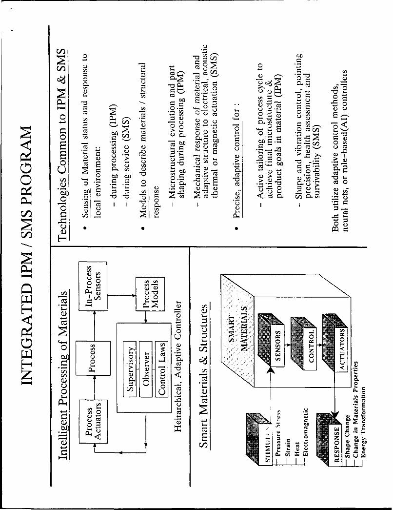
2.3 INTELLIGENT PROCESSING OF MATERIALS
During this program, it was evident that a primary obstacle to DoD implementation ofSmart Materislv.'Itructures (SMS) concepts and prototypes was the lack of a manufacturing base
for the active materials (e.g. electrostrictive ceramics, shape memory alloy, etc.) required forimplementation, and of a manufacturing base for embedding the various sensor and actuator
subsystems into composite material and other material systems. Results of an evaluation by
TRW (shown in Appendix B) address the suitability of several composites with respect to the
embedding materials.The manufacturing base in active materials can be developed using the Intelligent
Processing of Materials (IPM) paradigm for control of a material manufL...:uring process. IPMrelies on the development of three enabling technologies including in-situ sensing of the process,
modeling of the evolution of the process, and intelligent or adaptive control. Formally, the
following definition is suggested for IPM:
Intelligent Processing of Materials (IPM) - Active, ADAPTIVE CONTROL of materialsprocessing utilizing IN-PROCESS SENSING of critical microstructural, geometrical,and overall product features as they evolve during processing, utilizing analytical andheuristic MODELS of the process to MODIFY the process schedule (e.g. time histories of
7

6DM FEDERAL, INC. BDM-VAS-0784-93-TR
temperature, pressure, gas flow rates, etc.) as required during processing to achieveoptimized, reproducible product goals.
A block diaeram of an IPM system is shnwn in Figure 2.3-1. The basic goal of IPM is t(
develop a processing capability for engineered materials with specific properties. The need for
smart composite materials that are engineered to have specific properties is substantial. Forexample, the effectiveness of piezoceramic composites could be improved by introducing an
[PM system that examines the evolution of permittivity during processing, in order to maximize
the permittivity of the final product. Alternatively, IPM could be applied to grow large diameter
and highly crystallographic magnetostrictive crystals, so as to permit the implementation of
actuators for high-force and low-displacement applications. Further, problems associated with
the embedding of actuator or sensor components in a composite material could be resolved
through the application of IPM, by using the embedded smart sensor/actuator as the in-process
sensor, such as in the emnbedding of fiber optic sensors in a polymer composite.
[• Process PoesI-rcsActuators -' Prcs _ -rcSSensors
Supervisory
Observer Process
I ModelControl Laws
Hierarchical AdaptiveController
Figure 2.3-1. Block diagram implementation of Intelligent Processing of Materialsparadigm using BDM's hierarchical adaptive control system architecture.
2.4 INTEGRATED IPM - SMS PROGRAM
An interesting aspect of both the SMS and IPM technology areas is the significant
amount of overlap between the trwo. This overlap is illustrated in Figure 2.4-1.
8

"BDM FEDERAL, INC. BDM-VAS-0784-93-TR
BDM, as part of the successful team which bid on DARPA I 92-15 on the topic area of
Synthesis and Processing of Smart Materials (the team consists of Martin-Marietta, Lockheed,
and AVX, along with u-,iversity and government laboratory participation) seeks to accelerate the
development of Smart Materials and Structures and transition them to existing and future
military systems, but even more significantly, to transition these technologies to commercial
applications. The ultimate vision of this industrial - academia - government lab Partnership is to
develop a broadband smart material comprising two distinct actuator materials with operational
capabilities at both the micro (micron) and macro (millimeter) scale, that can sense, respond, and
cancel acoustic and vibrational energy.
The Partnership has the potential to have an immense impact on numerous military and
commercial systems. In addition, the Partnership identified several technology insertion targets
largely as identified by BDM under this program:
Electro-optic (EO) targeting systems such as LAINTIRN night vision system to
enhance pointing resolution and precision
sion Sral stic ed dar Optical Mutunn
Active Co-locatIdVariable Control of 3-D Spatial Electrically Optical ConsorsControl Control Noise and Light Tuned Phase andValves Vibration Modulator Waveguide Conjugator Actuators
Solid State Adaptable.Missiles Missiles, Smart Skins. Scene E!ectronically Laser Beam.. Machine-ToolsSpacecraft Aircraft, & Machinery Generation Scanned Steering. Vibration andLand-based Underwater Acoustic:::: Simulation & Radar SelffTargeting Jitter-freeEngines Vehicles SuOpression Calibration DEW, Processing
Optical ATR
I Results: Early development & exploitation of these smart materials will result in lighterweight weapon systems, with significantly improved manufacturability and reliability. !
Figure 2.4.1. Pervasive impact of an integrated Intelligent Processing of Materials for
Smart Materials Structures (IPM/SMS) Program on DoD systems.
9

BDM FEDERAL, INC. B DM-VAS-0784-93-TR
"* Fleet Ballistic Missile System for enhanced range and precision"* Advanced control surfaces for underwater vehicles"* Improved pointing and tracking control of large flexible space structures"* Isolation of engine / transmission noise from aerospace and aircraft structures in
struts, pylons, etc."* Development of jitter-free adaptive compliance precision machine tools"* Automotive engine mounts
A Technology Applications Board has been established under Lockheed chairmanship to
define application requirements, encourage technology transfer, and facilitate participation in the
program by outside users including other ARPA Partnerships. The Partnership identifies five
major thrust areas:"* Synthesis and Processing of Multilayer Ceramic Actuators"• Synthesis and Processing of Shape Memory Foil"• Application of IPM to each process"* Integration of each actuator concept into a prototype, large-scale active vibration
canceller"* Integration towards an active vibration canceller at the micron scale
Significant and early deliverables of a prototype AVC, a proof-of-principle device at themillimeter scale, and an IPM-based process are proposed at the end of an aggressive, 18 month,
Phase I program.
3.0 SUMMARY OF SUBSTANTIVE INFORMATION FROM VISITS ANDMEETINGS
BDM personnel participated in the DARPA-sponsored Workshop in Smart Materials I
Structures in January, 1991. In conjunction with the University of California, Santa Barbara(UCSB) URI working group, a one-day workshop was organized by Dr. Tony Evans, UCSB, andDr. Eric Cross, Penn State, and focused principally on the electromechanical behavior of
piezoelectric (PZT and PZLT) ceramics and piezoelectric composites. Major gaps in knowledge
about these materials were identified. First, the effects of processing on long-term stability ofproperties of piezoelectrics are were not fully characterized. Surface flaws induced during
processing were shown to drastically affect useful lifetimes of these materials. The opportunities
in Intelligent Processing of piezoelectric composites should be evaluated, where fibers havepotential uses as structural elements, in-situ sensors during processing and in health monitoring
of the composite during service life. Additionally, Dr. Bill Ditto of Naval Surface Weapons
Center (NSWC), White Oak, Maryland, reviewed their efforts on magnetostrictive materials suchas Terfenol, which exhibit substantial modulus shifts as a function of applied magnetic field, and
10

BDM FEDERAL, INC. BDM-VAS-0784-93-TR
are envisioned in damping of mechanical vibrations in noise - sensitive applications aboard
submarines and damping of vibrations in precision machining of optics and high speed bearings.
BDM personnel attended a Workshop on Smart Materals hosted by the Defense Sciences
Research Council in La Jolla, California on 18 July 1991. Key presentations were made by
several Government program managers, as well as by Dr. Uchino of Penn State, who spoke about
commercialization of Smart Materials in Japan.
BDM personnel participated in the International Symposium and Exhibition on Active
Materials and Adaptive Structures in Alexandria, Virginia, on 4-8 November 1991. A prototype
smart materials/structures application was presented by Dr. N. M. Wereley (BDM) at the
conference. This paper describes an ultrastable microgravity vibration isolation softmount for
deployment in a space shuttle middeck locker that was developed using piezo-film actuators.
Active control of low frequency vibrations (0.01 to I Hz), and passive isolation of high
frequency vibrations, were experimentally verified, proving feasibility of the soft-mount concept.
During this conference, substantial information was collected on smart materials/structures
component technologies, as well as current research programs in potential DoD prototype system
technologies.
BDM personnel met with Dr. Kristl Hathaway (ONR) to discuss the potentials for
magnetostrictive materials for both sensor and actuator applications. It was recognized that
magnetostrictive materials are in a somewhat embryonic stage of development. It was
determined that a workshop on magnetostrictive materials - specifically manufacture of
magnetostrictive crystal, potential DoD applications, and potential implementations could
provide the impetus for technological innovation in magnetostrictive materials. A recent SPIE
conference (February 1992) had a day-long workshop on magnetostrictive applications. BDM is
exploring the potential for further workshops in order to derive the most benefit for
DARPA/DSO.
BDM developed a conceptual design for a micromechanical magnetostrictive actuator.
The concept involves using layered material to produce a magnetostrictive structure with
improved crystal orientation in order to achieve 30 - 40% increase in strain due to an applied
electromagnetic field. The actuator can then be used to improve the operating envelopes of
micromechanical de-tices such as a micromechanical tuning fork gyroscope. The gyroscopic
response of the micromechanical tuning fork to an input rate about the longitudinal axis between
the tines has substantial stability problems at high frequency due to time periodic dynamics.
Implementation of a micromechanical magnetostrictive actuator, with a suitable control
algorithm, will allow the gyroscope to operate at higher frequencies than is currently possible.
BDM is continuing to develop this concept.
II

BDM FEDERAL, INC. BDM-VAS-0784-93-TR
4.0 LIST OF MANUSCRIPTS SUBMITTED OR PUBLISHED
No manuscripts were submitted or published under ARO sponsorship during this
reporting period, including journal references.
5.0 SCIENTIFIC PERSONNEL SUPPORTED BY THIS PROJECT AND DEGREESAWARDED DURING THIS REPORTING PERIOD
The following scientific personnel were supported during the reporting period: Dr. PA.
Parrish, Dr. C.J. Coe, Dr. R.B. Raphael, Dr. Tony F. Zahrah, and Dr. Norman M. Wereley.
6.0 REPORT OF INVENTIONS (BY TITLE ONLY)
None to report.
REFERENCES
1. DARPA Briefing. "Smart Materials, Devices, and Structures," Feb. 21, 1990.
2. The Concept of Intelligent Materials and the Guidelines on R & D Promotion," Japan Science
and Technology Agency, Nov. 30, 1989
3. Advanced Composites with Embedded Sensors and Actuators (ACESA)," Final Report for
Period 28 Sept. 1988 - 1 March 1990, R. Iregami, D. G. Wilson and J. H. Laarso, Beoing
Aerospace and Electronics Division, Aerospace Systems Technology Organization, P.O.
Box 3999, Seattle, WA 93124, AL-TR-90-022 prepared for Astronautics Laboratory
(AFSC), June 1990.
12

BDM FEDERAL, INC. BDM.VAS-0784-93-TR
APPENDICES
A SMART ACTUATOR CONCEPTS FROM THE ACESA PROGRAM
Concept of operation and evaluation of four smart actuator concepts from the ACESA
program (Ref 3):
13

BDM FEDERAL, INC. B DM-VAS-0784-93-TR
Concept of Operation
1I I I H
Positive strain Compressive strain
4Polarization direction
Applied Field
• When a field is applied parallel to X3direction a positive strain S3 results
* An opposite field of the same magnitude gives a compressive strain S3
d31 coefficient characterizes strain perpendicular to poling direction X1 andX2 directions) due to an electrical field aligned with poling (X3) direction.Usually considered a secondary, poisson-like effect resulting from strain duetoD 3 3 .Sl=d 31 E 3
• Evaluation
"* Stroke limited to maximum of 300 m strain"• Demonstrated embedability in Gr/Ep composites"• Very high bandwidth (greater than 20,000 Hz)"* Ceramic material-very fragile"• Requires very high drive voltages (200-400 volts)"• MIT has demonstrated control of composite beam with embedded
piezoelectric ceramic actuators
Figure A-1: Piezoelectric ceramic actuators ( from Ref. 3).
14

BDM FEDERAL, INC. BDM-VAS-0784-93-TR
Concept of Operation
Magnetostrictive materials:
- A magnetic field is applied to an anisotropic material with randomly distributeddomains. The domains will rotate to align with the magnetic field. Thiscauses internal strains in the material which result in a positive expansion ofthe material in the direction of the magnetic field.
Electrostrictive materials:
- Electrostrive materials self-polarize. Applying a field of these electrostrictivematerials begins the process of aligning the randomly oriented electric
domains. As the domains align, the material elongates.
" Magnetostrictive material offer no advantage over electrostrictivematerials due to overhead
" Electrostrictive stroke peak to peak 2000m strain Piezoelectricstroke 300m strain
" Electrostrictive stroke highly nonlinear at high ends requiringbiasing resulting in similar strain range to piezoelectric
" Some technology development required
" Neither magnetostrictive nor electrostrictive materials offer anyadvantages over piezoelectric ceramics
Figure A-2: Magnetostrictive and electrostrictive actuators (from Ref. 3).
15

BDM FEDERAL, INC. B DM-VAS-0784-93-TR
""" iqP 4P qP P 41 R F uid
Concept of Operation
- Changes in electrical field imposed upon the fluid can alter the yield strengthof the fluids. By introducing fluid in voids in a composite structure thestiffness and damping characteristics of the composite structure canbe changed
* Evaluation
- Creates large voids in composite material
- Extensive technology development required
Figure A-3: Electro-rheological fluid actuator (from Ref. 3).
16

BDM FEDERAL, INC. BDM-VAS-0784-93-TR
* Concept of Operation
- Produce SMA in basic shape (wire, rod, tube, sheet) Z- Form into the desired memory shape Z- Clamp into fixture.." -, SMA in Martensite- Heat treat (anneal) - condition - soft-Strain to desired shape ._ . z m
SMA in Austenite"Add heat condition - hard
Reverts to memoryset with high energyrelease
- Remove heat and strain to repeat cycle
- Evaluation
- Results of thermal analysis for NiTiNOL wire embedded in Gr/Ep
* Rise times are limited by the circuits ability to supply power andovercome induciton effects
* Cooling times are limited by the material surrounding the NiTiNOL
* Cooling will be needed to maintain acceptable temperatures for fastcycling and long soaks
- Large force capability with lightweight
- Simple electronics
Figure A-4: NiTiNOL shape memory alloy (SMA) actuators (see Ref. 4).
17

BDM FEDERAL, INC. BDM-VAS-0784-93-TR
B EVALUATION OF POTENTIAL FOR POLYMER RESINS AS EMBEDDING
MATERIALS FOR SMART SENSOR/ACTUATOR SYSTEMS
Typical Systems: Gr/Ep, Gr/BMI. Gr/PI
"• Advantages:
- Mature materials and processes
- Large experimental base
- Tailorable CTE
- Documented physical and mechanical properties
"• Disadvantages:
- AO, UV, and radiation protection required
- Outgassing, and moisture absorption controlled with coatings
- Hostile threat vulnerability
- Low processing temperatures (250" - 650" F)
S/A embedding potential:
" Processing temperatures only preclude embeddingpiezoelectric films
"• Embedding fiber optics and Nitinol alreadydemonstrated
"* Hand layup, tube rolling, filament winding easilyallows embedding
Figure B-i: Evaluation of Thermoset Composites (Ref.3)
18

BDM FEDERAL, INC. BDM-VAS-0784-93-TR
Typical Systems: Gr/PEEK, Gr/PPS
"* Advantages:
- Potential for low-cost fabrication
- Better toughness than thermosets
- Potential for simplified
- Versatility in processing
- Low out-gassing
"• Disadvantages:
- Up-front component development costs can be high
- Lack of experience base in processing
- Property variability due to processing
- Difficult to adhesively bond
S/A embedding potential:
"• Processing temperatures exceed fiber opticcoating limits
"• Thermoforming, roll-forming, filament windingstill in development
"* Hand layup, tube rolling, filament winding easilyallows embedding
Figure B-2: Evaluation of Thermoset Composites (Ref.3)
19

BDM FEDERAL, INC. BDM-VAS-0784-93-TR
C EXISTING SMART MATERIALS/STRUCTURES PROGRAMS
WHERE WHO WHAT
1. AFSC C. Browning Active Structural Control2. A. R. 0. A. Crowson, R. Ghirardelli Smart Structures3. Bertin et Cie (France) Pierre Sansanetti Smart Structures4. Boeing Co. K. Talat FOS; Smart Skins
5. Caltech J. Brady ER Fluid Research6. Canadian Marconi Z. J. Lu FOS for Strain7. Catholic Univ. A Bax et al SMA Actuators8. Cranfield Inst. Tech. H. Block ER Fluid Research9. Duke Univ. S. K. Das et al Adaptive Structures
(Space)10. E.R. Fluids Devel. Ltd. J. Stangroom ER Fluid Research
11. Fla. Inst. Tech. P. G. Grossman et al Smart Struc., FOS12. Ga Tech Hanagud Piezoceramics, PVDF13. Lord Corp. Cary N. C. Duclos Smart Materials
14. MDAC El. Sys. Div. Eric Uda Smart Materials15. M.I.T. Crawley, Anderson Piezo-Ceramic Actuation16. MSU M. V. Ghandi E. R. Fluids17. NAWC P. A. Raiti Smart Structures Skins18. NASA/Langley R. S. Rogowsky Active Control of
Space Structures19. NRL B. B. Rath Self Assembly;
Smart Mat'ls20. NRL Adv. F. 0. Res. GP. C. R. Crowe Fiber Optic Systems21. N. Car. State U. Y. Choi et al ER Fluids for
Vibration Control
22. Penn State Newnham, Cross Smart Ceramics23. Simmonds Precision W. Stillman Active Control24. Stanford Univ. A. Gast (CHE) ER Fluid Research25. TRW Space Tech Gp. Integ. Space Structures26. Wayne State Rivin Passive Self-Adaptive
Structures27. Wright Aero Labs Stevens, Ghirardi Health Monitoring,
20

BDM FEDERAL, INC. BDM-VAS-0784-93-TR
Structural Integrity.28. U. Ariz. P. Calvert Polymer Fiber Composites29. U. Fla Gainesville Zimmerman Vibration Control of
Structures30. Univ of Quebec/Hull W. T. Bock FOS for Strain31. U. Illinois C. Zukoski ER Fluid Research32. Univ. Maryland J. S. Sirtis Smart Structures
33. U. Minn James SMA's (Theory)34. Univ. of Strathclyde Brian Culshaw Smart Structures
35. U. Toronto Measures, Turner, et al FOS; Strain for
Smart Structures
36. UTRC James Dumphy Smart Structures37. U. Utah Ctr. Eng. De.ign Micro-Electronic &
Mech. Systems
38. Va Tech Furey Tribopolymerization39. Va Tech FEORC Claus FOS-Design, Mfr, Test40. Va. Tech SMSL Rogers, Ahmad,Robert Shaw Dynamic Control, SMA's
21

BDM FEDERAL, INC. BDWVAS-0784-93-TR
D FINAL BRIEFING MATERIALS PREPARED FOR ARO
Final briefing materials supplied to Dr. Robert Crowe (ARO). This is an abbreviated
version of a briefing package containing over 80 pages of material, which was prepared for ARO
by BDM during the program.
22
-0 a. -. ) y (t
1~ Ca
4-4 - -a
0~c C/)
uc~ QC)
-z v 0 -0 -o )
00 0 =j >
Q C/ ~ ~ I)C- 10 e)Q :
CI) ~C 00 --
4 0-
.O-
00
In Sal)

cc Lo2I
caJ
0-0
734 E.4r4 E -
0-4~
o I
In-
0,
01t
co ca:
rrA
0 !i ail -iiiiiijii i /. ii ii} : : i
S:::::::::::::::::::::::::::::::::: :•4. )
C/)•I:ssis~~~~i!: ::::@:.:: :: :: :: : :::: :: :::: :: ::-: :
i : :::::::::::::::::::::: :::: : : - ii~•i•:........ .. . .
- - ii - c ii :~~:•. !}i~~i .}ii!
:2-. 0i:!~iiii:ii :•ii: • id:~•m• ~ ~ ~- i - ::.5:::: .:24-.22 2 55J•52•::5
- ;;;.:#ii iii• I•Z i i::: i:i.?:iii:i~i:i: ~ilk ;:i ii i •• ::0:
H .00 .i:)~~~i•::!i
0-I•~~~~~, 0- , ; ...• •::;a: :
H: i~

0
zc-o0
0
U P4
*-A~00o 0> 4)CI) CIO
0~
CCIS 0~~
-4
C) Qcz... 0z_ Z- 00 .~ '3.
- ~ 4. C) ,Cu OH CZ - U
U' - CZ~
h0 CIa
CZ~C
0 bO .- A 1-4
C) '3) = ~
4- 6-4
CuZhc
" CZ

- 04
Qj 64 0u Cc
P2 w
CuU
*- "ca
060

BDM FEDERAL, INC. BDM-VAS-0784-93-TR
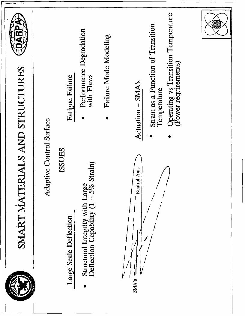
E BRIEFING MATERIALS PREPARED FOR DARPA
Briefing materials supplied to Dr. Ben Wilcox (DARPA) describing how IPM and SMStechnologies have synergy for long term advances in Smart Materials system applications.
27
r c---.-
con
_u2
ci00
zccn0
-z 03m0
-I- w U b - 0 -
cz. Cd Q
c) a)C13 & c))
zz ýc/ c
0i E
00 b
Cd4 W-4
C/I)
a) Q) CODcc 0 " a
0 ~~ V)~'oc 00/)
4.4 0 4-A> <H

cc
(.. c/ En
H4
zo __W

hil
406 Qi-h
ow -0 Ch
CJL

W ir0 z
a) utnE.0 : tw
. - Uip
40hi0Cc ~ ~ .0~ 0~uu~0
W*" z u)
-~Mm
II
60C8
cis~
0 U)
.4.0
U) C L tw )
-H Cc- ~ ~ CD
Cc MOW
CU W
W" 0-4 60)I)
0.%
4-
"0 * *zU
4-A--HA00

C).-
-0 'I
CIO ~
H ci~cz
H v i
zz L._ _
LD in m
wzz
U-M
-a 1=
IT,.
.4-. e ;.
H 04

CDC
.3 ____i.E__j
- a CD c'>..
ClC)
Q cý - )0nig- .~I~Q
-S
04-4
0
Cl)4- -rd >zLg a
Ci Ln
cc to x) r. CM 0 C! ~ a
91-1 )CXNOIIVZINWld 03ZVTVKS0"N-O()/VC..d)

CZS
u 0 CIO C
'J" a
iIii I
II!z- 6I
0c
b C~ ~)
H C.) ->
czz
V))
cu Q.)'-I
.~ ~ -4I-

CZ U
Ci~Cl
'-..
Cd13
-4 b
Hc

V-4-U Li
Li
V-o-H -Cc
-J c
man
0~~ 00.sub twi'O ho SOV H =Z.
H3Nl 3MO ýG SCNld=0SOIrX

BDM FEDERAL, INC. BDM-VAS-0784-03-TR
F RELATED WORK PREPARED BY BDM PERSONNEL
During the program, related activities were pursued by BDM personnel at no cost to the
program.
Dr. Norman M. Wereley prepared a paper on a prototype micro-gravity vibration
isolation mount using PVDF film as actuators. This paper was presented at the International
Symposium and Exhibition on Active Materials and Adaptive Structures in Alexandria, Virginia,
on 4-8 November 1991. The PVDF film is a polymer exhibiting piezo-electric properties. The
paper is attached.
40

UICROGRAVITY ISOLATION FOR SPACECRAFT PAYLOAD'
.MI. Mlercacal. 2 C.A. Blaurock. 3 A.H. von Flotow. - and N.M'. Wereiev 3Department of Aeronautics and Astronautics: "Mlassachusetts Institute of Technology,Rm 37-335: Cambridge. .MA 02139
ABSTRACT. A laboratory prototype of a six axis microgravity isolation mount is pre-S-entea. to provide a microgravi:v or micro-GEE (9.81 x 1.-0rn i/s) vibration payload envi-ronment on board a miili-GEE (9.81 x 10- 3 m is') spacecraft. The design can be adaptedfor N ASA space shuttle or Space Station Freedom missions. T-fe mount accomodates data.power. and cooling umbilicals of limited stiffness. Actuators are currentiv implementedusing piezoelectric film.
1. MICROGRAVITY ISOLATION REQUIREMENTS
Mlission specialist Bonnie Dunbar. on mission STS 32. measured acceleration ievels above 10mGEE (9.81 x 10- 2 M/s 2), especially when the crew members perform treadmiii exercise. Fig-ure I f'tom "1] shows a typical vibration time history measured in the orbiter cabin. Preventiveactions. such as shutting off unnecessary motors or restricting crew physical exercise. can reducevibration during vibration sensitive experiments, but is impracticai for extended periods.
Current NASA/ESA specifications consider harmonic disturbances onlv. M.ore stringentrequirements on the combined effects of broad-band GEE-jitter i crew motion. control thrusterfirings. sound etc.) and narrowband disturbances i antennae motion, rotating machinery, breath-ing etc.I rieed to be developed [2]. The single harmonic concept puts upperbounds on knownnarrowband disturbances and produces a curve of environmental disturbances as shown in Fig-ure 2a W3.. The desired curve is Figure 2b. a combination of [4] and NASA specifications (21from :31. The two curves clearly emphasize the need for isolation.
2. MIT SIX AXIS ISOLATION MOUNT
The vibration isolation concept involves softly mounting an inner box to the shuttle. so thatvibrations of an outer container are not transmitted to the inner box. A 2 cm Lap is providedbetween the inner box and the outer box. following recommendations by [3]. A mount travel of1 cm is accomodated before the mount -bottoms out" on rubber bumpers. T:iis is four timesgreater than the travel implied by the transmissibility specification of Figure 2. A 1 cm sinusoidat 0.01 Hz produces 4 micro-GEE of acceleration.
The soft mounts are implemented using piezo-electric (PVDF) film. The film. in appropriateshape configurations. behaves like a soft spring to mechanically isolate the inner box from theouter box. Second. the film deforms when voltage is applied, and can be used as an actuator.Active feedback control is used to increase damping, and to further soften the mount. Combined
t Presented at the International Symposium and Exhibition on Active Materials and Adavtive Structureu.Alexandria. Virginia: November 4-8. 1991. Substantially revised version of a paper presented at the 42ndCongress of the International Astronautical Federation: Montreal. PQ, Canada: October 7-11. 1991. Thisresearch was supported by the McDonnell-Douglas Space Systems Company with technical monitors Y.T. Chungand J.J. Tracy.
2 Visiting Scientsst. Currently: Compagnie Dassault. Paris. France.'Research Engineer.4jAociate Professor
sRcsearch Scientist. Currently: Staff Member. Control and Sensor Technology, BDM International Inc.. 4001N. Fairfax Dr.. Suite 750. Arlington, VA 22203

44 3
Cd, I-?., ,
-4 f - n=1_ __ _
10 20TIME (seconds) 0.01 0.1 i 100
Fraeqncv tHzu
Figure 1: Shuttle middeck vibration time Figure 2: Single harmonic vibration require-
history during STS 32 flight ments by Jones et al
active and passive action limits the need for active control: open ioop performance of the mount
is quite good. even though it falls short of the specifications in Figure 2.
Actuators were mounted so that three transiations and three rotations of the inner box can
be equally well controlled. Coupling between the six derees of freedom is minimized to simplify
control application. Each actuator is paired with an accelerometer. Decoupling the dynamics
enables the entire system to be identified on the ground with partial tests only. This reduces
the requirement for on-orbit identification. The control system can also be validated on the
ground before launch.From a survey of proposed microgravity experiments. flow of information, power. coolant,
and vacuum must occur between the payload and spacecraft. Utility umbilicals will add stiffness
to the system which is undesirable. so that umbilical stiffness should be minimized in order to
achieve as soft a passive mount as possible. reducing the need for feedback control.
3. EXPERIMENTAL APPARATUS
The isolation system has been sized so that the isolated payload fits inside two standard NASA
Space Shuttle middeck lockers. Wvle Laboratories f.5]. has developed the Universal Small
Experiment Container (USEC) system shown in Fiure 3. which fits inside two snace shuttle
mid-deck lockers and satisfies NASA safety standards for experiments flown on the shuttle. The
USEC is proposed since microgravity payloads such as crystal growth or biologicai experimentsrequire this degree of containment. The isolation system is part of the payload as far as the
integration process is viewed by NASA.
The piezo-film actuators were modelled as a displacement source in series with a spring.The primary role of the actuators is to overpower the utility umbilicals and soften the mount.
The payload box is nominally still, so that little control effort is used to overpower payload
inertia. The utility umbilicals were lumped together and given a stiffness equivalent for all axes.
Thus. the force on the actuator is the umbilical stiffness times the box relative motion. The
derivation of actuator stiffness and free deflection is detailed in [61. The actuators. as configured
in Figure 4. actuate all six axes. and each kinematically actuates only one degree of translation
and rotation. Rear actuators were doubled up to maintain equal control authority in the X
axis. The actuators were nominally fiat to maximize payload volume. The total mount stiffness
measured was 5 N/m per axis. The mount was designed to handle an umbilical with 20 N/m
stiffness. The design and fabrication of the actuators is detailed in [6].
The experiment focused on actuator validation. so that a mock-up of the locker and payload

. . . . . . . . . . . . . . . . ... . . . . . . .
N ... V
.............. ............
Figure 3: The Wyle Laboratories USEC Figure 4: Actuators are configured such
containment box satisfies NASA's contain- that two push at each location.
ment specifications for the shuttle middeck.
A~ A
Figure 5: Experiment hardware. Figure 6: Placement of coolant umbilical.
was fabricated with representative dimensions and properties. During proof-of-concept, easy
access to system components was required. As shown in Figure 5. the front panel was open to
permit payload removal. Bumpers prevented damage to the actuators due to excessive payload
motion. Actuator attachment locations were provided on all four longerons. and at the rearvertical bar. The actuator attachment hardware allowed nominal centering of payload. The
payload rested on an air table with rninimial damping, to permit free movement in the horizontalplane.
Actuator power was supplied by three Kepco BOP 1000M high voltage ampiifiers, for which
their maximum current output of 40 miliiaznps proved to be barely sufficient. Three shakers
were used to excite the system, one for axial motion. and two at the side of the locker, to allow
"2 transiations. and rotation around the vertical axis. The shaker heads were connected to the
core of an LVDT linear position sensor, so that transmissibility from locker motion to payload
acceleration could be measured directly.
Sundstrand QA-1400 accelerometers were mounted on an adjustable platform that could
be tilted to remove the accelerometer's DC bias by cancelling it with a component of gravity.
Looped computer ribbon cable was used for the sensor umbilical. The modes of the experiment

with the ribbon cable in place were comparea to the dynamics of the pavioad with acceierome-ter connections of very thin magnet wire. Utility umbilicais consisting of acceierometer cablingand a simuiated coolant hose. sufficient for 1 HW of cooiinz with less tnan 50 deerees Celsiustemperature increase, were imDiemented. The system ID places constraints on the umbilicallocations, since some coupling terms in the stiffness matrix cannot be identified i61. The um-bilicais were attached svmmetricaily about the payload center of mass. as shown in Figure 6to rr'nimize unidentified coupling. Each cooiant hose was ioooed. so tiat the hose was neverstretched. The stiffness was fouhd to be 8.2 N,'m in the X direction. and negiigible in the Yaxis.
4. SYSTEM IDENTIFICATION
Ref. 161 details an analytical model of the system based on system geometry. its mass and inertiacharacteristics, the umbilical and actuator stiffnesses. This model is valid at low frequency(below about 10 Hz) where the control system exercises most of its authority.
Mechanical properties. such as mass. inertia, or stiffness, can be measured, or computed fromdetailed engineering drawings. However. system identification of the physicai system shouldprove convenient information suitable control design. The six axis mount couid be identifiedon-orbit. However. system ID would be time consuming d'ue to low natural frequencies of themount. xith computational reaurements far exceeding those ior closed iooD control. Thus. wepropose six axis ground-based system ID. usinz three sets of three axis system identificationtests. A single three ax-is test consists of resting one side of the inner box on an air tablewhile suspending the outer box appropriately. This setup allows two translations and onerotation. and permits the identification of a projection of the unrestricted six degree of freedommotion. The accuracy and the validity of this strategy depends strongly on the decoupiing ofthe dynamics. After the three 3-axis tests are performed. the identified stiffness matrix. K. isknown except for those entries designed to be small. that is. identification cannot determine:helicoidal spring constants where a translation produces a torque in the same axis or torsionalspring constants not aligned with one of the geometrical axes. Such springs have however beeneliminated by design. Details of the 3-axis system identification is deferred to Appendix 1 of(6].
Singie-input multi-output system ID of the three axis testbed was performed using a Tek-tronix 2630 Fourier analyzer. which computed transfer functions. and conerence functions. Anensemble average of 15 runs takes 39 min 45 sec. A weighted least mean square aizorithm wasused to determine a state space model 161. The test was performed on the system equipped withtwo rubber hoses attached on the Y sides of the inner box to simulate the cooling apparatus.Excellent agreement is obtained for both magnitude and the phase. The resonant frequenciesare a-. .'"24 Hz and 0.181 IHz for the Y and X translational modes (the umbilical separatesthe itequencies) and at 0.273 IHz for the rotational Z mode. Comparing with a second testperformed without umbilical. the umbilical stiffness is estimated at 8.2 N/m. which is withindesign specifications.
Modal damping was identified to be between 4% and 6%ý. Also. the damping matrix. C. wasnot aligned with the stiffness matrix, so that modal decoupling was not compietely effective.In Figure - the transfer function (magnitude only) of the decoupied plant is plotted. Theoff-diagonal elements of the transfer function matrix are substantially smaller than those onthe main diagonal. but are not negligible.

i- I
1 3 xsts ihunii: magnitud
r 7 I I
The. coto objctve se b,' th S/S udlns ,rqietecoe opplso h
SI0 I 0 I - /I
5.COT.O ORECII
isolated payload to be at 0.05 Hz (curve a) or 0.01 Hz (curve b), with a damping ratio above0.707. The control strategy is to combine sensor and actuator signals to modally decouple
the syvstem. and close a single input single output (SISO) control loop around each of the6 decoupled modes. The advantage of nhe decoupnng strategy over purely localized controlbetween collocated sensors and actuators is that spread in modal frequencies can be equalized
due to the spread in the stiffness matrix. With such a well-conditioned plant. however, sixlocalized feedback loops are still possible. one for each (local) sensor/actuator pair. In order to
drive the fastest mode to the required frequency. heie localized scheme wiil require higher gains.To reduce the natural frcquencv of the system, modal mass must be increased, or modal
stiffness must be decreased. To improve modal damping and phase margins, velocity feed-back was implemented. Acceieration feedback was selected for this application. over positionfeedback. because accelerometers were much less expensive than gap sensors of comparablesensitivity. Gap sensors can be easily accomodated in the current controller framework. andmay be implemented in future work.
The design target will be to set the closed loop modal frequencies w.i = 0.01 Hz (requirementa) or jI = 0.05 Hz (requirement b), with damping c = I to eliminate overshoot. However,
phase losses from digital controller implementation and anti-aliasing filters will decrease closedloop damping.
The high-pass filter is a two-pole filter with corner frequency at 0.02 Hz. The corner fre-
quencv of the high pass filter was selected to prevent saturation of the actuators due to biasesand bias drifts present in acceierometers and associated conditioning amplifiers. The filters en-sure that modal mass is added oniv in the frequency range of interest. Thie high-pass filter adds
phase lead and may reduce the amount of damping provided by the feedback loop. especially ifthe filter frequency is too high. The low-pass filter is a one-pole filter at 0.3 Hz followed by atwo-pole filter at 10 Hz. The double pole filter at 10 Hz reduces high frequency accelerometer

OP04 LOOP VERSW CLA5E WOW WRAIJhsuzy
lot LOOP WOOP A UNP P " ! 0oo)8 : . , . . -: . . ,-• - .. .: '---.. .I,• - . .. : ..
• I',~l •mmm m ICl
101
-wy InqI lo fHZ
Figure 8: Loop transfer function of Z rota- Figure 9: Open versus closed loop trans-
tion mode, 0.2726 Hz. with filters missibility of Z rotation mode
noise. and serves as anti-aliasing filters. in orGer to maintain stabilitY, a one pole roil off is
neeceed at cross-over with enough phiase iead to prevent instabilities. The corner frequency of
0.3 liz was selected for that purpose.The filters have a significant effect on the closed loop Cynamics since their corner frequencies
are close to the natural frequencies of the system. be it closed or open loop. The high-pass
filter reduces the phase lag introduced by the integrator and will therefore reduce the amount
of passive damping in the system. However. the 0.3 Hz iow-pass filter adds sc-ne phase lag and
compensates somewhat for the lead. The choice of the mni and c; must therefore be iterated
until a satisfactory compromise is reached. The closed loop frequencies and damping will bevery different from the prediction based only on the second oscillator model for the modes. The
target for the closed loop is to set the modes at 0.04 IHz with as much damping as the wash-out
filter can allow. The accieration feedback gain. mr.). and the veiocity feedback gain. c,.). chosenin the experiment are: X Translation Mode. 0.1807 1Hz. m- = 4. c- = 4: Y Translation Mode.
0.1236 lIz. my = 2. cl. = 2: Z Rotation Mode. 0.2726 Htz. n7- = 10. c. = 10. The nominal
closed loop poles are: V translation. 0.0141 Hz. 35%, dammni: AT transiation. 0.042 Hz. 41%
dammnin: Z rotation. 0.040 Hz. 40% damping.
-le loop transfer function. the predicted closed loon versus open loop transmissibility and
the sensor noise to acceleration spectrum is plotted for the stiffer Z rotation mode in Figures 8-9.
These results are representative of all three modes.
6. CLOSED LOOP 3 AXIS GROUND EXPERIMENT
Control system was implemented part anaiog and part digital. Analog low-pass filters served
the double purpose of attenuating the sensor noise and anti-aliasinz. The control computer was
an IB. I Model PS/30(286). The accelerometer signals were sampled with an Analog Devices
RTI-_00 A/D converter. The control algorithm was implemented in Microsoft Quick C and ran
at 1.'.2 Hz. The high-pass filter was realized digitally due to its very low time constant. The
digital control signal was passed to the Analog Devices RTI-S02 D/A output. The D/A outputto the current amplifier drove the piezo-electric actuators.
First. we compare the open and closed loop transient responses. Figure 10 shows the three
open loop accelerometer time traces recorded simultaneously for 40 seconds developed after
a impulsive disturbance was applied (the experimenter blew on the inner box). The three

"--N LOOP 7WAN-- d .. AC2U.tO?.0NY Ot LCOO 1RANSIIMf6 ACELE ma.1, "i
al- : •sl--- - -
- -'• "" - 7 - - I o-' -.. '
2V 'N LOOP TXAJf5TL'f ACCEU., T ER. '1. _" LOOP 1ANSTIT ACCOELERO.lrr C
02.2). - - .,2. • , .
).4 'fIL LOOP TWANS1T'f! ACCL23.ONWTE~ 3 -- 2= LOOP 1WANSWTI -AC O!OWTER 91
~ -'4t. -~
Figure 10: Open loop acceleration transient Figure 11: Closed loop acceleration tran-sient
modes of the system are excited and damping levels are small. Figure 11 shows the threeacceierometer time traces recordered simultaneously for 40 seconds with active control. Theimpuisive disturbance was applied to a corner of the inner box designed to to excite all three
modes. The time period of the oscillation is close to 25 seconds, or 0.04 Hz. The motion is alsomore strongly damped.
Experimental transmissibility curves were also obtained. A single shaker was used to excite
all three modes. Z rotation. X and Y translations. Shaker motion was measured by a LVDT dis-placement sensor. The transmissibility, or the transfer function between accelerometer output
and LVDT output. was obtained using the Textronix Fourier anaivzer. Transfer function unitsare Accelerometer Volt / LVDT Volt. The DC gain is not equal to i as predicted by the analyt-ical model. Figure 12 compares the open and closed loop transmissibility for accelerometer #3.
Note that the open loop natural frequencies have shifted due to the umbilical stretching overtime. thereby increasing stiffness. Damping has greatly increased, and the closed loop naturalfrequency has decreased. The maximum attenuation seen in the transmissibility is observed at0.3 Htz on Figure 12 where the attenuation is greater than 36 dB. or reduced by a factor of 70.
T. SUMMARY
The six axis microgravity isolation mount prototype developed at MIT is a practical solutionto isoiating vibration sensitive payloads on board nililiGEE svacecraft such as the NASA spaceshuttle or space station. The isolation system can be visuaiized as two boxes. The inner box,containing the payload. is mounted to an outer box the voiume of two NASA Space Shuttle
middeck lockers. The inner box is attached to the outer box via several soft springs made ofpiezo-eiectric film. and soft utility umbilicals. The passive mechanical isolation is then enhanced
actively using the piezo-film actuators. The payload has provision for cooling, datalink andpower through umbilicals of limited stiffness.

SHAKER #2 TO ACCELEROMEMTh #3 TRANSMISSIBIUrTY
, :: OPEN LOOP
4 : - ,
10
CLASED LOOP
10 100, 10' 10'
frequency iHZI
Figure 12: Comparison of exoerimental closed loop and open booD transmissibility between shakerno. 2 and accelerometer no. 3
The mount is designed to minimize interaxis coupling. Thus. ground-based system identi-fication via three axis tests is sufficient to identify the six axis system, and provides enoughinformation for control system design. The inertia and stiffness matrix are nominally diagonaland tile location of the sensors and actuators makes modal control the natural approach. Activedamping and mass are added to each mode via velocity and acceleration feeedback. respectively,such that the compensator is essentially a lag compensator. The control philosophy has beenvalidated by the test performed on the 3 axis identification testbed.
REFERENCES
'1] B. J. Dunbar. D. A. Liomas. and J. N. Schoess. --The microgravity environment of thespace shuttle Columbia middeck during STS-32." Tech. Rep.. NASA. 1921.
[2] E. S. Nelson. "An examination of anticipated g-jitter on space station and its effects onmaterial processes." Tech. Rep.. NASA. April 1991. NASA Tecb -ical Memorandum 103775.
[3] D. I. Jones. A. R. Owens. and R. G. Owen. "A microgravity isolation mount." Acta Astro-nautica. vol. 15. pp. 441-448. 1987.
[4] C. Tiby and D. Langbein. "Allowable g levels for microgravity payloads.- Tech. Rep.. BatelleInstitute. Frankfort. 19S5. ESTEC contract 5504/83.
[3] R. Giuntini. "Developing payload systems: there is a lot to it." Tech. Rep.. \WYLE Labo-ratories. 7800 Governors Drive. PO Box 07777. Huntsville. AL. 1991.
[6] M. Mercadal. C. Blaurock. A. H. von Flotow. and N. MI. Wereiey. "'Laboratory prototype of asix-axis microgravitv ioslation mount." Tech. Rep.. Dept. of Aeronautics and Astronautics.M.I.T., 1991. Final Technical Report submitted to McDonnell Douglas SDace Systems
Company. ___