bd-2100 manual - moisture meters delmhorst · 5 testing wood 5 paint failure and moisture 6...
TRANSCRIPT
1
BD-2100
BUILDING MATERIALS MOISTURE METER OPERATION MANUAL
DELMHORST EUROPE
TITANIUMLAAN 100
NL 5221 CK ‘s-HERTOGENBOSCH
THE NETHERLANDS
www.MoistureMetersDelmhorst.com +31 (0)73 6395080
2
Model BD-2100
Owners Manual
TABLE OF CONTENTS
2 BD-2100 Features
3 Section A - Before You Begin
3 Button Functions
3 Check Calibration
3 Set the Scale
4 Change the Set Point
4 Information About Your Readings
4 To Check Accumulated Readings
4 To Reset the Meter
5 Section B - Practical Applications
5 Testing Wood
5 Paint Failure and Moisture
6 Temperature correction table
6 Pin correction table
7 Species correction table
8 EIFS (Exterior Insulation & Finishing Systems)
8 Testing Gypsum
8 Using the 0-100 Reference Scale
9 Testing Plaster Walls
9 Testing Concrete Slabs for Flooring Applications
10 - Taking a surface reading
- Key factors to consider.
11 Testing Brick or Concrete for Paint Application
12 Detecting Moisture in Insulation
13 Care of Your Meter
13 Service For Your Meter
14 Warranty
BD-2100 FEATURES
Designed to check moisture levels in wood, concrete, EIFS, sheetrock and other materials.
Resistance technology recognized worldwide as the most accurate method for measuring
moisture
6% - 40% moisture range for Wood
0.2%-50% moisture range on gypsum
0 to 100 relative scale for all non-wood materials
Digital readout
Includes sturdy carrying case
Easy one-hand operation
Includes (1) 9-Volt Battery
Proven microcontroller circuit
One year warranty
Over 50 fifty years of proven quality, accuracy and service
The operating instructions for the model BD-2100 are divided into two sections. Section A is a
systematic guide to the different features and basic use of your moisture meter. Section B
contains information on how the meter is used for testing different materials.
Please read the instructions carefully. If you require additional information, please contact
Delmhorst for assistance.

3
SECTION A - BEFORE YOU BEGIN
BUTTON FUNCTIONS
#1 Read Button - This button reads the Percent Moisture Content value (%MC), in the user-
selected scale.
#2 Calibration Check Button - This button checks the meter calibration. It also displays the
average of up to 100 accumulated readings; displays the maximum stored reading; erases the
readings.
#3 Scale Button - This button sets the display scale to #1 (Wood), #2 (Plaster/Concrete
reference scale), and #3 (Gypsum). This button also acts as a scroll key, depending on the
function.
#4 Set-Point Button - This button programs the set-point value. A buzzer will alert you if the
meter reads higher than the selected value. This button also acts as a scroll key, depending
on the function.
CHECK CALIBRATION
Press the read button (#1) and calibration check button (#2) simultaneously. Meter is
in calibration if it displays 12% (+ or - .2). Make sure the pins are not in contact with
anything when checking the calibration.
If you check the calibration and the meter does not display 12% it is likely an indication of a
low battery. If this occurs, change the battery immediately. Continued use with a low battery
may cause the meter to go out of calibration. If you have a fresh battery and the instrument
still does not indicate a proper calibration, return it to DELMHORST for service. See “Service
for your Meter” section. When the battery is removed and then reconnected, the meter
displays its software version for one second and then turns itself off. After replacing the
battery, you must reset the meter as described in “Resetting the Meter” section.
SET THE SCALE
Set the scale for #1 Wood, #2 Plaster/Concrete reference scale, or #3 Gypsum.
To change the scale, press the scale button (#3). The meter will display the current
scale for one second.
To scroll forward through the scales hold the scale button (#3) while the current scale
is displayed and scroll to the scale desired.
To scroll backward through the scales, press and hold the set-point button (#4) within
one second of pressing and releasing the scale button (#3). Continue to hold the set-point
button (#4) and the scale number will decrease.
When scrolling in either direction, release the button to stop at your desired scale.
Changing the scale will automatically reset the set-point value to the default setting for that
particular scale. Default settings are as follows:
#1 #2 #3
Wood Scale -15% Plaster / Concrete Reference Scale - 85% Gypsum Scale - 1%

4
CHANGE THE SET-POINT
To change the set-point value, press the set-point button (#4). The meter will display
the current set-point value for the scale you have chosen for one second.
To scroll forward to a higher value for that scale hold the set-point button (#4) while the
current set point is displayed and scroll to the set-point value desired.
To scroll backward through the set-point values, press and hold the scale button (#3)
within one second of pressing and releasing the set-point button (#4).
Continue to hold the scale button (#3) and the set-point value will decrease.
When scrolling in either direction, release the button to stop at your desired set point.
INFORMATION ABOUT YOUR READINGS
The meter will accumulate up to 100 readings. After all 100 readings are “stored” it will not
add new readings until the memory has been cleared. It will also continue to display the
average of all 100 readings as a reminder that the memory is full.
To add a reading to the sum of all the previously stored readings, release the read button
(#1) within 2 seconds.
When taking and storing readings of a specific material, be sure to “clear” the meter before
moving on to the next scale if you do not want to group all of the readings together.
TO CHECK ACCUMULATED READINGS
This feature allows you to view the total number of all accumulated readings, for the given
material you have chosen, the average of those readings, and the highest stored reading.
To view the readings press and release the calibration check button (#2). First the
meter displays the number of accumulated readings for one second, then the average of
those readings for two seconds. Then it displays the highest stored reading for two
seconds. The total “cycle” time is five seconds.
To erase readings hold the calibration check button (#2) down for 5 seconds. All
accumulated readings will be erased and the meter will display “0”.
To keep the accumulated readings in memory, release the calibration check button
(#2) before the meter finishes the above cycle.
TO RESET METER
Press and release the calibration check button (#2).
Within one second, press the scale button (#3).
The meter will reset itself the default setting of Scale #1 (wood) and 15% set point, and
clear all the readings stored in memory.
Resetting the meter will erase any previously stored readings.
5
SECTION B - PRACTICAL APPLICATIONS
TESTING WOOD:
Set the scale for #1 Wood
Align the contact pins parallel to the grain and push them into the wood to their full
penetration, if possible.
Press the read button (#1). The meter displays the %MC for two seconds.
If the displayed reading is above the set-point value, the set-point buzzer will sound. In
addition, one of the LEDs on the front panel will light up as follows:
Wood Scale #1
Green - 6% to 15% Yellow - 15% to17% Red - > 17%
The LEDs are a visual aid to help quickly determine the moisture level that each reading
indicates. Readings that activate the green light indicate a sufficiently dry moisture level,
those that activate the yellow light indicate a borderline situation, and those that active the red
light indicate material that is too wet for most applications.
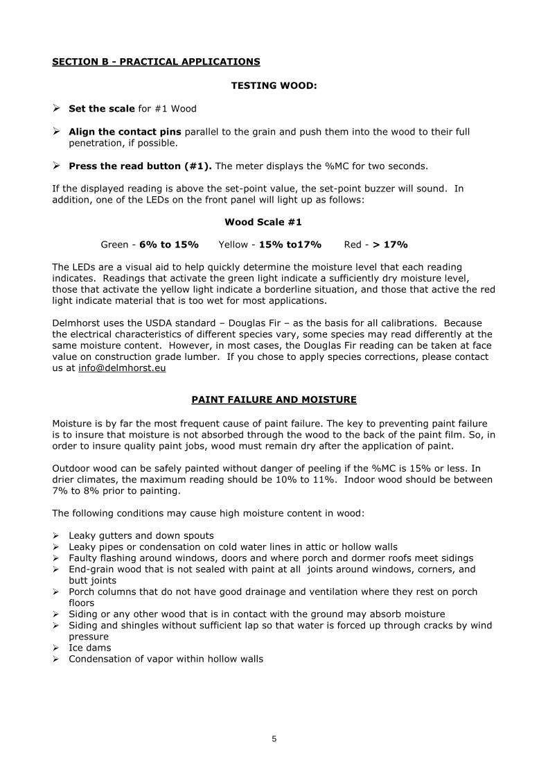
Delmhorst uses the USDA standard – Douglas Fir – as the basis for all calibrations. Because
the electrical characteristics of different species vary, some species may read differently at the
same moisture content. However, in most cases, the Douglas Fir reading can be taken at face
value on construction grade lumber. If you chose to apply species corrections, please contact
us at [email protected]
PAINT FAILURE AND MOISTURE
Moisture is by far the most frequent cause of paint failure. The key to preventing paint failure
is to insure that moisture is not absorbed through the wood to the back of the paint film. So, in
order to insure quality paint jobs, wood must remain dry after the application of paint.
Outdoor wood can be safely painted without danger of peeling if the %MC is 15% or less. In
drier climates, the maximum reading should be 10% to 11%. Indoor wood should be between
7% to 8% prior to painting.
The following conditions may cause high moisture content in wood:
Leaky gutters and down spouts
Leaky pipes or condensation on cold water lines in attic or hollow walls
Faulty flashing around windows, doors and where porch and dormer roofs meet sidings
End-grain wood that is not sealed with paint at all joints around windows, corners, and
butt joints
Porch columns that do not have good drainage and ventilation where they rest on porch
floors
Siding or any other wood that is in contact with the ground may absorb moisture
Siding and shingles without sufficient lap so that water is forced up through cracks by wind
pressure
Ice dams
Condensation of vapor within hollow walls

6
Pin correction: METER READINGS WITH INSULATED PINS (26-ES ELECTRODE) 7 8 10 12 14 16 18 20 22 24 CORRECTED READINGS (TRUE INDICATED MOISTURE CONTENT) 7.3 8.4 10.6 12.8 14.9 17.0 19.2 21.4 23.7 26.0
7

8
EIFS (Exterior Insulation & Finish Systems) *
Moisture intrusion problems in EIFS (also known as synthetic stucco) stem from leaking
window frames, improper use of or lack of sealant, and faulty installation of flashing.
If you suspect a problem, take a visual inspection. Look for gaps around windows, doors, air
conditioning units, light fixtures, hose bibs, dryer vents and other areas of potential
penetration. Also, look for visible signs of water damage. If you feel a problem exists, use the
BD-2100 meter with a # 21-E electrode. This electrode includes the #608 - (4")
insulated pins.
Procedure:
Drill two 1/4" holes about ¾” apart at an upward 45° angle.
Push the # 21-E Electrode into the holes through the polystyrene and into the
substrate.
Press read button (#1) and read the moisture content on the scale.
* Refer to the wood scale #1 if the sheathing is plywood. If gypsum sheathing is
used, refer to the gypsum scale #3
TESTING GYPSUM
Set the scale for #3 Gypsum.
To take a reading, push the contact pins into the gypsum to their full
penetration, if possible.
Press the read button (#1), and read the moisture content on the display. The meter
displays the reading for 2 seconds.
The set-point buzzer will sound if the displayed reading is above the set-point value. In
addition, one of the LEDs on the front panel will light up as follows:
Gypsum Scale #3
Green - 0% to 0.5% Yellow - 0.5 to1% Red - > 1%
The LEDs are a visual aid to help quickly determine the moisture level that each reading
indicates. Readings that activate the green light indicate a sufficiently dry moisture level,
those that activate the yellow light indicate a borderline situation, and those that active the red
light indicate` material that is too wet for painting or wallpaper.
USING 0-100 REFERENCE SCALE
When taking a reading on hard materials such as concrete or masonry, use Scale #2 to
determine a qualitative reading.
Tests should be made on samples of material that are known to be dry. Such readings can be
used as standard or reference points, against which subsequent readings are compared. All
readings should be evaluated in the light of factors such as type of paint, type of construction,
and climatic conditions.
The set-point buzzer will sound if the displayed reading is above the set-point value. Also one
of the LEDs on the front panel will light up as follows:
0-100 Reference Scale #2
Green - 0-85 Yellow - 85-95 Red - >95

9
The LEDs are a visual aid to help quickly determine the moisture level that each reading
indicates. Readings that activate the green light indicate a sufficiently dry moisture level,
those that activate the yellow light indicate a borderline situation, and those that active the red
light indicates material that is too wet for most applications.
TESTING PLASTER WALLS
Under normal drying conditions and proper application of plaster (sufficient drying time
between coats), surface readings give accurate results. However, if rapid drying occurs, the
surface of the plaster may be dry, but moisture is still present below the surface and will
eventually affect the paint or wallpaper. This condition occurs when there is high temperature
or exceptionally good air circulation, or where brown scratch and white coats are applied within
a few days. Take several readings on each wall. Pay special attention near the base, around
doorjambs, electrical and plumbing fixtures, and other places where the plaster is thicker than
normal.
Taking a surface reading:
Drive the contact pins into the plaster to their full penetration, if possible
Press the read button (#1) and read the reference scale.
Taking a reading below the surface:
Drive a pair of nails into the plaster at least 1/3 of the total thickness of the plaster.
If you are applying plaster to a material of doubtful dryness, such as brick or concrete,
drive the nails through the plaster and into the brick or concrete.
Touch the heads of the nails with the contact pins and read the meter.
TESTING CONCRETE SLABS FOR FLOORING APPLICATIONS
Moisture meters are an effective tool to check moisture in concrete. They can tell you where
there may be excess moisture and help determine if you need to conduct further testing.
It is important to test both the surface and mid-section of the slab, especially if the slab is on
or below grade. This will help determine if there is continuous moisture migration toward the
surface. If this condition exists, the moisture movement may be so slow that once it reaches
the surface, moisture evaporates and causes a “dry” reading when a surface test is made.
However, if a sub-surface test is made, the meter may read “wet” indicating the presence of
moisture. When the slab is covered and the upward movement of moisture continues,
moisture will move into a hygroscopic (wood) floor, or build-up pressure under a non-
breathing synthetic floor, causing delamination.

10
Taking a surface reading:
Drive two hardened-steel masonry nails about 3/4" apart into the finish coat of
concrete floor. Drive them about 1/8" deep so they make firm contact with the
concrete and do not move when touched.
Touch the nails with the contact pins.
Press read button (#1) and read the scale. If the meter reads in the red or “wet”
area, it shows the floor is not satisfactory for covering. If meter reads in the green or
“dry” area, the surface is dry. However, subsurface tests should be made to verify if
the slab is dry throughout.
Subsurface test:
Drill two 1/4" holes, 3/4" apart and 1/2" to 2" deep.
Drive the masonry nails into the bottom of the holes and make the tests as described
above. Nails must not touch sides of drilled holes.
If the meter still indicates green or “dry” the floor is ready for covering. Tests should be made
at several points, especially when the slab is thick and air circulation is poor. Tests should only
be made in newly drilled holes, since the inside surface of the holes can dry out while the rest
of the slab is still wet.
Even readings in the red or “wet” area can indicate relatively low moisture content in concrete.
For example, readings in the 85-95 range on the reference scale indicate approximately 2% to
4% moisture content.
If more testing is required, the calcium chloride test is recommended, which measures the
moisture vapor emission rate of concrete. The National Wood Flooring Association offers the
following guidelines when evaluating the results of the calcium chloride test***:
RESULTS INDICATE
0-3 lbs. Dry
over 3 lbs. Moisture barrier required
over 7 lbs. Too wet
Key factors to consider:
The age of the slab. National Wood Flooring Association guidelines specify to wait at
least 30 days after the slab is laid before checking moisture content.***
Color of the concrete. Color of good healthy concrete should be almost sugar-white.
Concrete that is gray, brown, tan, or off-white may have contaminants, admixtures, or
problems that may affect the flooring installation.
Is the slab on grade or suspended? If the slab is on grade, is there an effective
vapor barrier under the slab?
How thick is the slab?
What is the drainage condition of the ground?
History of other structures in the area
***Taken from Section V Appendix AA “Moisture Testing Procedures for
Concrete Slabs” – NWFA

11
TESTING BRICK OR CONCRETE FOR PAINT APPLICATION
Brick, stucco, or concrete surfaces must be dry at the time of application and must remain dry
after paint is applied or failure of the paint film may occur. These materials are frequently
exposed to unusual moisture conditions that allow them to absorb moisture through some
exposed surface or some structural defect. This is why it is important to check the moisture
content of the brick or concrete when it has been exposed to conditions that permit it to
absorb moisture.
Procedure:
Drive two hardened steel masonry nails about 3/4" apart into the brick or concrete.
Drive them about 1/4" deep so they make firm contact and do not move when touched.
Touch the nails with the contact pins.
Press read button (#1) and read the reference scale.
Normally, dry concrete or brick will read in the green or “dry” portion of scale, indicating a
safe condition to apply paint. Meter readings should be evaluated in relation to other
factors -- knowledge of the structure, type of paint used, expected weather conditions in
the near future, etc. Paint should not be applied if readings are in the red or “wet” portion
of the scale.
Do not be misled by surface appearance of masonry materials. Short exposure to rain may
thoroughly wet the surface while the interior is still dry. In this instance, we recommend
repeating the test on the masonry below the surface as mentioned above.
Key areas to check:
The rear sides of brick parapet walls -- generally are not waterproof above the
flashing line and frequently absorb moisture during rains
Painted concrete floors on ground -- subject to peeling as they absorb moisture
from the earth, unless an effective vapor barrier has been installed
Tests on these materials should be made a day or so after they have been exposed to rain or
other high moisture conditions to verify to what extent they absorb moisture
Tracing Leaks
The BD-2100 can help trace leaks in masonry material. Normally, dry plaster, brick, or
concrete will contain so little moisture it cannot be detected by the meter. If the meter
indicates the presence of moisture you can trace the moisture to its origin.
To trace the origin of a leak:
Drive a nail into an area that is known to be wet and attach an insulated wire
between the nail and one of the contact pins.
Apply the other pin to various parts of the wall where you suspect the leak originates.
If the meter indicates red or “wet”, the material is wet between the points of contact. If the
meter reads green or “dry,” the material along this line is not in the path of a leak.
To confirm if a brick wall is waterproof:
Perform the following procedure after storms to verify if a brick wall is waterproof, or if
waterproofing repairs have been properly performed:
12
Drive pairs of nails into the brick wherever it is necessary to make the tests and leave
them in place until after all the tests are completed.
Take readings after each storm, and record the readings. The pattern of these readings
will indicate if the brick is gradually drying out or is moistened again by each storm.
Detecting Moisture In Insulation
Use the BD series meter with the #21-E Electrode and #608 insulated pins to detect
moisture in insulation. These pins are insulated, except at the tips. Only the uninsulated tips
make contact with the material, providing information as to the depth at which moisture is
present.
Procedure:
Drill two 3/16" diameter holes, one inch apart through the siding.
Using the #21-E, insert the #608 contact pins into the holes so that you make contact
with the insulation.
Press the read button (#1)and take a reading. Take readings at various depths of
penetration to determine the location of moisture.
Fill holes with putty at the conclusion of the test.
Meters are not calibrated to read the percentage of moisture content in the insulation. Instead,
meter readings provide a qualitative indication of the presence of moisture. The meter may
also help identify the pattern of distribution to help you determine if moisture is due to
condensation or leakage.
The presence of moisture in insulating material greatly reduces its insulating properties. If the
insulating material absorbs moisture, water will displace the air in the material. Water also
transmits heat at a faster rate than air, thus reducing the efficiency of the insulation.
Side walls and roof insulation pick up moisture because of leaks in the roof or structural
defects in the side walls which allow storm water to be forced in during high wind. During
periods of cold weather, vapor will condense as it approaches the colder area near the outside
walls, and resulting moisture will remain trapped in the insulation.
Cork, wood fiber boards, and other cellulose material read lower than glass wool and other
inorganic type of insulation.
13
CARE OF YOUR METER
To keep your meter in good working order:
Store your meter in a clean, dry place. The prote
ctive carrying case provided is an ideal storage place when the meter is not in use.
Change the Alkaline 9-Volt battery as needed. Continued use with a low battery may
cause the meter to go out of calibration. We strongly recommend to not use
rechargeable batteries.
Change contact pins as needed. Keep pin retainers hand tightened.
Clean the meter and contact pins with any biodegradable cleaner. Use the cleaner
sparingly and on external parts only. Keep cleaner out of the external connector .
Remove the battery if the meter will not be used for one month or longer.
SERVICE FOR YOUR METER
Pack your meter securely. Enclose a purchase order or letter with a brief description of the
problem.
There is no need to call us for a return authorization number if you are within the EU.
Customers outside the EU must contact us for more specific instructions prior to returning a
meter.
Include your name, address, daytime phone and fax numbers or e-mail address. If you
believe the meter is under warranty, please provide the original sales slip or invoice.
Ship via UPS, Express Mail, Priority Mail or any overnight courier who provides prompt
service. Do not use standard parcel post.
Insure your instrument for its full value and ship prepaid. We are not responsible for
damage in transit.
We do not accept COD shipments or cover any incoming freight or duty charges on
returned merchandise
Turnaround time on repairs is approximately two weeks.
We will call you with an estimate if you specifically request one, or if we determine that the
meter may be too costly to repair.
Non-warranty repairs will be returned via UPS/COD unless you have already established
other payment terms. There is no COD service outside the EU.
Payments have to be made by Bank transfer prior to the return shipment. A Proforma
invoice will be raised in advance.
Warranty repairs will be returned at no charge if shipped within the EU via GLS Ground
Service. Freight charges for expedited services (i.e., Federal Express, UPS/2 Day, UPS/1
Day, etc.) are the customer’s responsibility and will be charged as per the above terms.

14
WARRANTY
DELMHORST EUROPE, referred to hereafter as DELMHORST, guarantees your moisture meter
for one year from date of purchase and any optional electrodes against defects in material or
workmanship for 90 days. If, within the warranty period of the meter, you find any defect in
material or workmanship return the meter following the instructions in the “Service for Your
Meter” section. This limited warranty does not cover abuse, alteration, misuse, damage during
shipment, improper service, unauthorized or unreasonable use of the meter or electrodes. This
warranty does not cover batteries, pin assemblies, or pins. If the meter or any optional
electrodes have been tampered with, the warranty shall be void. At our option we may replace
or repair the meter. DELMHORST shall not be liable for incidental or consequential damages for
the breach of any express or implied warranty with respect to this product or its calibration.
With proper care and maintenance the meter should stay in calibration; follow the instructions
in the “Care of Your Meter” section.
Under no circumstances shall DELMHORST be liable for any incidental, indirect, special, or
consequential damages of any type whatsoever, including, but not limited to, lost profits or
downtime arising out of or related in any respect to the meters or electrodes and no other
warranty, written, oral or implied applies. DELMHORST shall in no event be liable for any
breach of warranty or defect in this product that exceeds the amount of purchase of this
product. The express warranty set forth above constitutes the entire warranty with respect to
Delmhorst meters and electrodes and no other warranty, written, oral, or implied applies. This
warranty is personal to the customer purchasing the product and is not transferable.
ARTTEST B.V.
Trade name DELMHORST EUROPE
TITANIUMLAAN 100
NL 5221 CK ‘s-HERTOGENBOSCH
THE NETHERLANDS
www.moisturemetersdelmhorst.com
+31 (0)73 6395080
For already 65 years, Delmhorst is a leading brand for high-quality resistance moisture meters.
Today the Delmhorst range consists of a complete line of portable moisture meters for a
variety of different applications including woodworking / lumber, agriculture, construction and
paper.