bbdd ttuurrbboo gguuaarrdd // bbllooww--ooffff · pdf filebbdd ttuurrbboo gguuaarrdd //...
TRANSCRIPT

31 August 2012 Part #’s 1047250AR / 1047250AS / 1047250SR / 1047250SS / 1047251SR / 1047251SS 1
BD Engine Brake Inc. Plant Address: 33541 MacLure Rd. Abbotsford, BC, Canada V2S 7W2
U.S. Shipping Address: 88-446 Harrison St, Sumas, WA 98295 U.S. Mailing Address: P.O. Box 231, Sumas, WA 98295 Phone: 604-853-6096 | Fax: 604-853-8749 | Internet: www.bd-power.com
BBDD TTuurrbboo GGuuaarrdd // BBllooww--OOffff VVaallvvee Installation Manual
Part Number Application
1047250AR General Application Kit, Aluminum Adaptor, Red Valve
1047250AS General Application Kit, Aluminum Adaptor, Silver Valve
1047250SR General Application Kit, Steel Adaptor, Red Valve
1047250SS General Application Kit, Steel Adaptor, Silver Valve
1047251SR 12 Valve Application Kit, Steel Adaptor, Red Valve
1047251SS 12 Valve Application Kit, Steel Adaptor, Silver Valve
* Read all instructions before beginning installation of this kit! *
OWNER’S MANUAL – LEAVE IN GLOVE BOX
Installation Manual Part # I1047250-251

31 August 2012 Part #’s 1047250AR / 1047250AS / 1047250SR / 1047250SS / 1047251SR / 1047251SS 2
BD Engine Brake Inc. Plant Address: 33541 MacLure Rd. Abbotsford, BC, Canada V2S 7W2
U.S. Shipping Address: 88-446 Harrison St, Sumas, WA 98295 U.S. Mailing Address: P.O. Box 231, Sumas, WA 98295 Phone: 604-853-6096 | Fax: 604-853-8749 | Internet: www.bd-power.com
TABLE OF CONTENTS
Welcome ................................................................................................................... 3
Special Tools Required ............................................................................................. 3
Pre-Installation .......................................................................................................... 4
Dodge 12/24V Auto Trans Install .............................................................................. 4
Intercooler Tube Removal ......................................................................................... 6
Intercooler Tube Installation ...................................................................................... 8
Spool Valve Installation ............................................................................................. 9
Dodge 12V Manual Trans Install ............................................................................. 11
Throttle Switch ............................................................................................... 11
Wiring & Plumbing Diagram ........................................................................... 14
Wiring & Plumbing Diagram ........................................................................... 15
Duramax Install (2001- 2004).................................................................................. 16
Wiring And Plumbing Diagram ....................................................................... 18
Duramax Install LLY,LBZ,LMM (2004.5- ................................................................. 19
Wiring And Plumbing Diagram ....................................................................... 20
Ford 7.3/ 6.0L (R/S) Installation .............................................................................. 21
Wiring And Plumbing Diagram ....................................................................... 23
Ford Powerstroke 6.4.............................................................................................. 24
Wiring And Plumbing Diagram ....................................................................... 26
TGE Adjustment & Testing ..................................................................................... 27
Troubleshooting ...................................................................................................... 30
OPERATING GUIDELINES .................................................................................... 30

31 August 2012 Part #’s 1047250AR / 1047250AS / 1047250SR / 1047250SS / 1047251SR / 1047251SS 3
BD Engine Brake Inc. Plant Address: 33541 MacLure Rd. Abbotsford, BC, Canada V2S 7W2
U.S. Shipping Address: 88-446 Harrison St, Sumas, WA 98295 U.S. Mailing Address: P.O. Box 231, Sumas, WA 98295 Phone: 604-853-6096 | Fax: 604-853-8749 | Internet: www.bd-power.com
Welcome
Thank you for purchasing a BD Turbo Guard kit. This manual is divided into different areas to assist you with your installation of the different kits and operation of the Turbo Guard.
The BD Turbo Guard is one of the nicest units on the market. The body and all internal components are CNC machined from 6061 aluminum alloys. It features the one of the largest dump valves at a whopping 1.98” (50.5 mm), which gives you the highest flow in the industry. A V-Band clamping system allows easy installation and removal. The valve seal utilizes a Viton O-ring that is clamped in place to prevent the possibility of sticking to the seat and pulling out. The valve stem and guide are Teflon lubricated and hard anodize coated for wear resistance.
Special Tools Required
Drill with 1 7/8” hole saw
Crimping Pliers
Test light
¼” Drive Socket set
Small Blade tip screwdriver
MIG or TIG Welder (Aluminum feed for the Duramax kit)
Teflon tape or putty
5/32” Allen key

31 August 2012 Part #’s 1047250AR / 1047250AS / 1047250SR / 1047250SS / 1047251SR / 1047251SS 4
BD Engine Brake Inc. Plant Address: 33541 MacLure Rd. Abbotsford, BC, Canada V2S 7W2
U.S. Shipping Address: 88-446 Harrison St, Sumas, WA 98295 U.S. Mailing Address: P.O. Box 231, Sumas, WA 98295 Phone: 604-853-6096 | Fax: 604-853-8749 | Internet: www.bd-power.com
Pre-Installation
** PLEASE READ THIS MANUAL COMPLETELY BEFORE
INSTALLING THE BLOW-OFF VALVE ** To prevent damage to electronic components, it is recommended that you disconnect both negative battery terminals before starting.
Dodge 12/24V Auto Trans Install
This kit is designed for the Dodge Cummins 12 or 24 Valve with an APPS/TPS voltage source. You will be using the new Turbo Guard Electronics (TGE) module to determine when to activate the valve. It is recommended that you mount this module underneath the steering column inside the cab to keep out any moisture or dirt from under the hood. Locate a switched 12 Volt power source in the fuse panel with a test light. You can also use the supplied fuse tap and flag connector for another power source as well.

31 August 2012 Part #’s 1047250AR / 1047250AS / 1047250SR / 1047250SS / 1047251SR / 1047251SS 5
BD Engine Brake Inc. Plant Address: 33541 MacLure Rd. Abbotsford, BC, Canada V2S 7W2
U.S. Shipping Address: 88-446 Harrison St, Sumas, WA 98295 U.S. Mailing Address: P.O. Box 231, Sumas, WA 98295 Phone: 604-853-6096 | Fax: 604-853-8749 | Internet: www.bd-power.com
This 12 volt switched power should go to the “Switched Power” input on the TGE module using the supplied red wire. You will need to use a set of crimping pliers to connect the connectors on the power side of the red wire.
When connecting the power wire to the TGE, there are special quick
connectors that allow an easy installation. Trim the proper amount of
insulation off of the wire and be sure to tighten the locking screw on the green
quick connector. Be careful that there are no cross shorts between cables.
Also check to make sure that the green connection block is firmly inserted
into the TGE case. You also need to locate a clean ground location which should be wired into the “Ground” input on the TGE module using the supplied black wire and ring connector. Usually a bolt will protrude from the firewall, which makes a good ground. Please again trim excess wire. Route the gray and violet wires through the firewall and into the engine compartment. The violet wire should be connected to the TGE input labeled
“APPS” and the grey wire should be wired into the TGE output labeled “Output”.
Location Year Wire Color
APPS/TPS Sensor
Or at ECM
2004-05 Brown w/ White Tracer
2003 Yellow
1994-2002 Light Blue w/ Black Tracer
PCM 1994-2003+ Orange w/ Dark Blue Tracer
The violet wire from the Turbo Guard kit should be connected to the APPS signal. Reference to the chart above for which wire to tap onto. This signal is located at the driver’s side front of the Cummins 24 valve engine above the injection pump on vehicles 98-03. On the 2004+ vehicles this wire will be located at APPS sensor on the throttle pedal. Use the supplied Posi-Tap™ to tap into the wire. Note that you may also tap into this wire at the PCM and as well at the Cummins ECM. This wire should range from approximately 0.5 volts to 5 volts depending on how far the pedal is depressed. At idle the voltage should be near the 0.5 to 1.0 volt scale and at full throttle it should read close to 3-5 volts. On 12 Valve engines the APPS/TPS is at the rear of the P7100 injection pump. Use the supplied Posi-Tap to tap into this wire and connect it to the violet wire. You may have to trim the excess wire.

31 August 2012 Part #’s 1047250AR / 1047250AS / 1047250SR / 1047250SS / 1047251SR / 1047251SS 6
BD Engine Brake Inc. Plant Address: 33541 MacLure Rd. Abbotsford, BC, Canada V2S 7W2
U.S. Shipping Address: 88-446 Harrison St, Sumas, WA 98295 U.S. Mailing Address: P.O. Box 231, Sumas, WA 98295 Phone: 604-853-6096 | Fax: 604-853-8749 | Internet: www.bd-power.com
Once the Violet APPS wire has been routed connect the Grey wire to the bullet connector on the spool valve that you mounted to the intake horn earlier. You will need crimping pliers to attach the opposite gender bullet connector to the grey wire. Route the wire inside of the supplied loom. Please be careful of routing the wires away from any heat sources or any moving parts.
Intercooler Tube Removal
Before welding the Blow-Off Valve adapter onto the cool side of the intercooler tube (driver side), you must remove it. Remove the two clamps located on the intercooler boots. Use a 7/16” deep socket to remove the top and bottom boot clamp. The adapter will be installed on the upper portion of the tube furthest away from the intercooler. Using a tape measure, measure about 2½ - 3” from the upper edge
of the tube and mark a drill spot. This mark should be the center of the adapter. As you can see from the picture above, the edge of the adapter should be within a ½ inch from the second raised lip. Once you have marked your drill location, use a center punch and drill a pilot hole. Use a 1-7/8” hole saw and drill out the remainder of the hole. Place the adapter and the tube in a vice in order to hold the adapter tight against the tube while welding. You can tack-weld the adapter if you are unsure of its proper location. After the weld is complete, be absolutely certain that the weld is strong and there are no air leaks.
Warning: Ensure the weld is
clean on the inside of the tube.
If any slag is left there is a
chance of engine damage.

31 August 2012 Part #’s 1047250AR / 1047250AS / 1047250SR / 1047250SS / 1047251SR / 1047251SS 7
BD Engine Brake Inc. Plant Address: 33541 MacLure Rd. Abbotsford, BC, Canada V2S 7W2
U.S. Shipping Address: 88-446 Harrison St, Sumas, WA 98295 U.S. Mailing Address: P.O. Box 231, Sumas, WA 98295 Phone: 604-853-6096 | Fax: 604-853-8749 | Internet: www.bd-power.com
After the weld has been cleaned, a nice coat of black paint is recommended to eliminate any tarnishing.

31 August 2012 Part #’s 1047250AR / 1047250AS / 1047250SR / 1047250SS / 1047251SR / 1047251SS 8
BD Engine Brake Inc. Plant Address: 33541 MacLure Rd. Abbotsford, BC, Canada V2S 7W2
U.S. Shipping Address: 88-446 Harrison St, Sumas, WA 98295 U.S. Mailing Address: P.O. Box 231, Sumas, WA 98295 Phone: 604-853-6096 | Fax: 604-853-8749 | Internet: www.bd-power.com
Intercooler Tube Installation
Use the supplied aluminum V band clamp to attach the Blow-Off Valve to the newly welded adapter. Do not forget to use the supplied Viton O-ring to seal the valve to the adapter.
Be very careful not to over-extend the V band clamp, as damage will result. Tighten the Allen bolt with a 5/32” Allen key so that the
valve is securely fastened to the adapter. Re-install the intercooler tube in the reverse order that it was removed. Be sure that all the intercooler boot clamps are securely tightened. Rotate the tube so that the Blow-Off Valve is facing towards the front the truck.
31 August 2012 Part #’s 1047250AR / 1047250AS / 1047250SR / 1047250SS / 1047251SR / 1047251SS 9
BD Engine Brake Inc. Plant Address: 33541 MacLure Rd. Abbotsford, BC, Canada V2S 7W2
U.S. Shipping Address: 88-446 Harrison St, Sumas, WA 98295 U.S. Mailing Address: P.O. Box 231, Sumas, WA 98295 Phone: 604-853-6096 | Fax: 604-853-8749 | Internet: www.bd-power.com
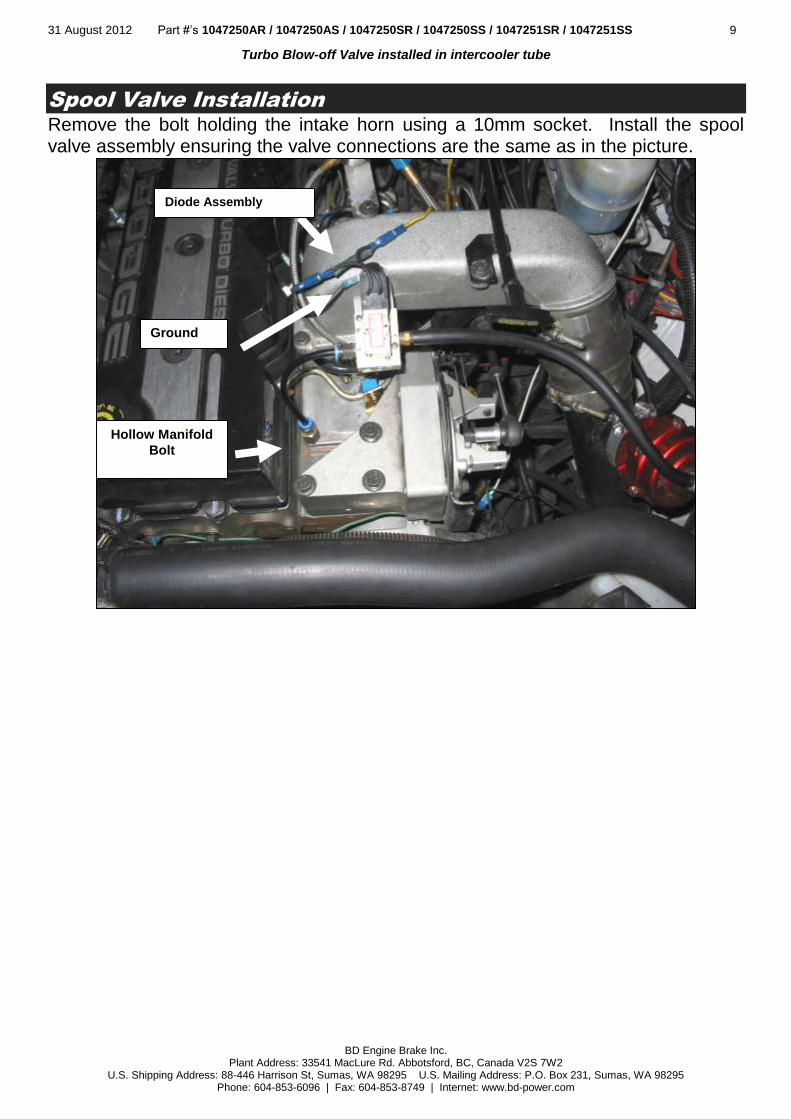
Turbo Blow-off Valve installed in intercooler tube
Spool Valve Installation
Remove the bolt holding the intake horn using a 10mm socket. Install the spool valve assembly ensuring the valve connections are the same as in the picture.
Diode Assembly
Ground
Hollow Manifold
Bolt

31 August 2012 Part #’s 1047250AR / 1047250AS / 1047250SR / 1047250SS / 1047251SR / 1047251SS 10
BD Engine Brake Inc. Plant Address: 33541 MacLure Rd. Abbotsford, BC, Canada V2S 7W2
U.S. Shipping Address: 88-446 Harrison St, Sumas, WA 98295 U.S. Mailing Address: P.O. Box 231, Sumas, WA 98295 Phone: 604-853-6096 | Fax: 604-853-8749 | Internet: www.bd-power.com
When securing the spool valve assembly with the long 10mm bolt, connect the spool valve ground (ring connector) between the intake horn and the spool valve assembly. Be sure to re-torque the 10mm bolt, or a boost leak may occur. Install the “Free Wheeling” Diode pigtail assembly. Route the power through the red wire and then into the spool valve. The black wire of the assembly should be mounted to ground using the ring connector. Use the rubber hose to connect the Blow-Off Valve to the brass push-on connector on the spool valve. Secure the connection using the supplied hose clamps at each connection point. Keep the hoses as short as possible. Remove the 10mm bolt that holds the intake manifold plate in place. Install the supplied hollow manifold bolt with the blue or green “quick-connect” connector in place. It is recommended that a small amount of sealing putty be used on the manifold bolt. Route the hard plastic tube from the manifold connector to the blue or green “quick-connect” connector in the spool valve. Please verify the following connection points as each connection is numbered in the picture.
Conn. Description
1
Engine Boost Pressure via “quick-connect” connector.
2 N/C
3 N/C
4 Blow-Off Valve via rubber air hose
5 N/C

31 August 2012 Part #’s 1047250AR / 1047250AS / 1047250SR / 1047250SS / 1047251SR / 1047251SS 11
BD Engine Brake Inc. Plant Address: 33541 MacLure Rd. Abbotsford, BC, Canada V2S 7W2
U.S. Shipping Address: 88-446 Harrison St, Sumas, WA 98295 U.S. Mailing Address: P.O. Box 231, Sumas, WA 98295 Phone: 604-853-6096 | Fax: 604-853-8749 | Internet: www.bd-power.com
If you are unsure about any connection, look through the next couple of pages and find your kit number. In your kit’s section you will find a wiring schematic that will assist your installation. Tighten the banjo bolt on top of the Blow-Off Valve securing the hose connection. You may also notice some pre-wired circuits connecting the ground to the power side of the spool valve. There should be a short diode harness wired as well. This is to remove any inductive spikes caused by the spool valve. Please trim any excess tubing or hose, trying to make the installation clean as possible. You will also notice that you received 4 shims in the kit as well. These shims are used to adjust the valve opening and closing pressure. The more shims you use, the higher the opening pressure.
Dodge 12V Manual Trans Install
This kit is designed for the Dodge Cummins 12 Valve with a standard transmission. A throttle pedal micro-switch is required for this application due to the fact that there is no TPS voltage. The purpose of this throttle switch is to indicate when then throttle is at the idle position.
Throttle Switch
At the throttle pedal, locate the nuts on the large aluminum bracket, just up from and to the left of the pedal. These nuts secure the aluminum bracket to the firewall and are the mount for the throttle and brake pedal. Remove the lower nut and loosen off the top nut. In the kit you will find the long throttle switch bracket, which has two long slots for the throttle switch. Slide the top end of the bracket (with the cut out slot) under the loosened upper nut and lay against the aluminum bracket so the stud that was exposed when you

31 August 2012 Part #’s 1047250AR / 1047250AS / 1047250SR / 1047250SS / 1047251SR / 1047251SS 12
BD Engine Brake Inc. Plant Address: 33541 MacLure Rd. Abbotsford, BC, Canada V2S 7W2
U.S. Shipping Address: 88-446 Harrison St, Sumas, WA 98295 U.S. Mailing Address: P.O. Box 231, Sumas, WA 98295 Phone: 604-853-6096 | Fax: 604-853-8749 | Internet: www.bd-power.com
removed the lower nut protrudes through the other slot on the Throttle Switch Bracket. Screw the lower nut back onto the stud, but do not tighten the nuts yet. In the kit, find the small 2-3/8” long bracket with two holes. The arm of the throttle pedal starts off wide, then angles off into a thinner section further up the pedal. Just before the pedals arm angles to the thinner section, place the middle hole of the bracket on the still wide section, close to the edge and angle the bracket towards the throttle switch on the other bracket you installed above. Ensure sufficient clearance between the long throttle switch bracket and throttle pedal by sliding the bracket as far to the left as possible, to eliminate any possibility of the pedal catching on the bracket. Adjust both brackets so that the small bracket you are holding on the pedal arm is going to make good contact with the throttle switch when the pedal is in its resting/idle position. Mark and drill the two holes on the pedal arm and screw or pop rivet the small bracket to the arm. Tighten the nuts for the aluminum bracket and make any necessary final adjustments to the throttle switch bracket on the aluminum bracket. Make sure the screws supporting the throttle switch and screws for the electrical wires on the switch are tight. Periodic adjustment of the throttle switch might be required to maintain proper contact with the bracket on the throttle pedal. Use the supplied line tapper or fuse tapper and find a 12v fused ignition switch power source and attach one side of the throttle pedal micro switch to the power source using the supplied red wire. Attach the long grey wire to the last connection on the throttle pedal micro switch and route the wire through the firewall. Continue to route the wire in a discrete

31 August 2012 Part #’s 1047250AR / 1047250AS / 1047250SR / 1047250SS / 1047251SR / 1047251SS 13
BD Engine Brake Inc. Plant Address: 33541 MacLure Rd. Abbotsford, BC, Canada V2S 7W2
U.S. Shipping Address: 88-446 Harrison St, Sumas, WA 98295 U.S. Mailing Address: P.O. Box 231, Sumas, WA 98295 Phone: 604-853-6096 | Fax: 604-853-8749 | Internet: www.bd-power.com
fashion to the bullet connector on the spool valve that you installed earlier on the intake horn of the engine. You will have to use a crimping tool to connect the bullet connector to the grey wire. Be conscious of moving or hot engine parts when routing the wire. Once all of the connections have been finalized and you are confident that everything is correct you may test all the connections. Turn the key to the “ON” position (KOEO). Press the throttle pedal up and down. As the accelerator pedal is applied, the spool valve should deactivate. A small click should be heard as the pedal is released and the spool valve should activate once again. You can test the circuit with a voltmeter or a test light. You must remember that when the key is “ON” and the throttle pedal is at an idle state the spool valve will be energized. As soon as the throttle is slightly pressed past idle position, the spool valve will deactivate. Refer to the diagram on the next page.
31 August 2012 Part #’s 1047250AR / 1047250AS / 1047250SR / 1047250SS / 1047251SR / 1047251SS 14
BD Engine Brake Inc. Plant Address: 33541 MacLure Rd. Abbotsford, BC, Canada V2S 7W2
U.S. Shipping Address: 88-446 Harrison St, Sumas, WA 98295 U.S. Mailing Address: P.O. Box 231, Sumas, WA 98295 Phone: 604-853-6096 | Fax: 604-853-8749 | Internet: www.bd-power.com
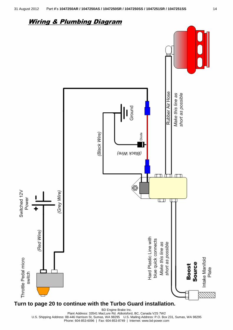
Wiring & Plumbing Diagram
Turn to page 20 to continue with the Turbo Guard installation.

31 August 2012 Part #’s 1047250AR / 1047250AS / 1047250SR / 1047250SS / 1047251SR / 1047251SS 15
BD Engine Brake Inc. Plant Address: 33541 MacLure Rd. Abbotsford, BC, Canada V2S 7W2
U.S. Shipping Address: 88-446 Harrison St, Sumas, WA 98295 U.S. Mailing Address: P.O. Box 231, Sumas, WA 98295 Phone: 604-853-6096 | Fax: 604-853-8749 | Internet: www.bd-power.com
Wiring & Plumbing Diagram
Turn to page 20 to continue with the Turbo Guard installation.

31 August 2012 Part #’s 1047250AR / 1047250AS / 1047250SR / 1047250SS / 1047251SR / 1047251SS 16
BD Engine Brake Inc. Plant Address: 33541 MacLure Rd. Abbotsford, BC, Canada V2S 7W2
U.S. Shipping Address: 88-446 Harrison St, Sumas, WA 98295 U.S. Mailing Address: P.O. Box 231, Sumas, WA 98295 Phone: 604-853-6096 | Fax: 604-853-8749 | Internet: www.bd-power.com
Duramax Install (2001- 2004)
The installation of the turbo guard for the Duramax is slightly different as the other applications although the concept is still the same. It is highly recommended that you read over the Dodge installation portion of this manual. The intercooler tubes that you will be mounting the blow-off valve adapter to are made of aluminum; hence you will need an aluminum welder to mount the aluminum adapter. The intercooler tube of choice is the turbocharger compressor outlet tube, which is located on the driver side. If you cannot mount it there, then the passenger side engine inlet will do, although you may suffer some response time. You will need to use the brass three-way adapter to tap into the wastegate line as a
boost source. The APPS/TPS wire that you are looking for is Dark Blue - it can be found on the accelerator pedal assembly inside the truck. A suggested location for the spool valve is on the trucks firewall over top of the engine ground strap. Remember to keep the plastic & rubber hoses as short as possible.
Use a ground strap bolt to mount the
spool valve.
Use a wastegate line as a boost
source.
Mount the valve on the compressor outlet of the intercooler tube
(before the
intercooler)

31 August 2012 Part #’s 1047250AR / 1047250AS / 1047250SR / 1047250SS / 1047251SR / 1047251SS 17
BD Engine Brake Inc. Plant Address: 33541 MacLure Rd. Abbotsford, BC, Canada V2S 7W2
U.S. Shipping Address: 88-446 Harrison St, Sumas, WA 98295 U.S. Mailing Address: P.O. Box 231, Sumas, WA 98295 Phone: 604-853-6096 | Fax: 604-853-8749 | Internet: www.bd-power.com
You will also notice that you received 4 shims in the kit as well. These shims are used to adjust the valve opening pressure. The more shims you use the higher the opening pressure.
Secondary mounting
location. When using
this location you will
need to find a
mounting bolt for the
spool valve.

31 August 2012 Part #’s 1047250AR / 1047250AS / 1047250SR / 1047250SS / 1047251SR / 1047251SS 18
BD Engine Brake Inc. Plant Address: 33541 MacLure Rd. Abbotsford, BC, Canada V2S 7W2
U.S. Shipping Address: 88-446 Harrison St, Sumas, WA 98295 U.S. Mailing Address: P.O. Box 231, Sumas, WA 98295 Phone: 604-853-6096 | Fax: 604-853-8749 | Internet: www.bd-power.com
Wiring And Plumbing Diagram

31 August 2012 Part #’s 1047250AR / 1047250AS / 1047250SR / 1047250SS / 1047251SR / 1047251SS 19
BD Engine Brake Inc. Plant Address: 33541 MacLure Rd. Abbotsford, BC, Canada V2S 7W2
U.S. Shipping Address: 88-446 Harrison St, Sumas, WA 98295 U.S. Mailing Address: P.O. Box 231, Sumas, WA 98295 Phone: 604-853-6096 | Fax: 604-853-8749 | Internet: www.bd-power.com
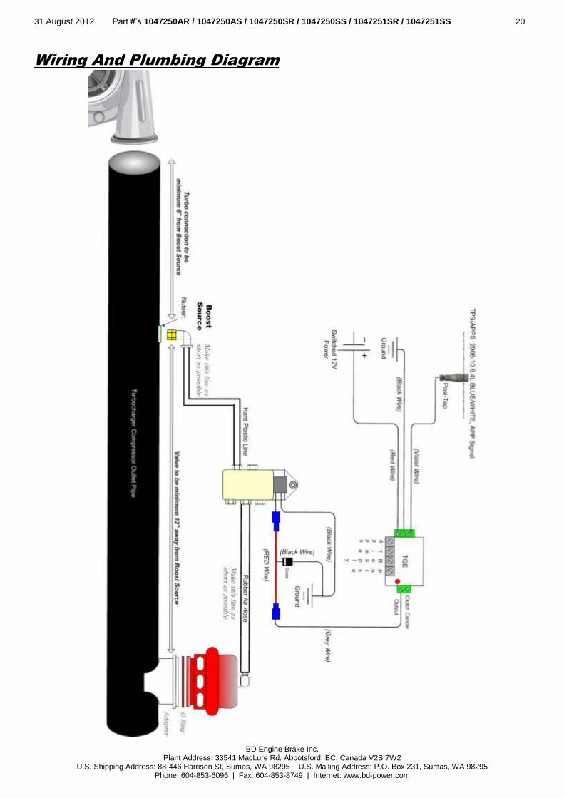
Duramax Install LLY,LBZ,LMM (2004.5-
Being that you have a VGT turbocharger you will not be able to pull boost pressure from the turbocharger waste gate line. Ideally it is best to install the unit on the turbocharger outlet tube (driver’s side). For the LLY you may have no choice but to install the unit into engine inlet pipe (passenger’s side). In the case of the LBZ and LMM you don’t have a choice and must install the unit on the turbocharger outlet pipe (driver’s side). Also it is very important that the boost pressure source for the top of the BOV be from the turbocharger outlet side. To install the boost pressure source there should be a nutsert included with the kit. You will need to remove the turbocharger outlet pipe and install the nutsert in it. Once this pipe is removed, drill a 3/8” hole on the top of the pipe closest to the turbo. Use a file or de-burring wheel to clean to hole. Coat the nutsert with a moderate temperature silicon or gasket maker. Insert the coated nutsert into the 3/8” hole in the pipe. Insert the Allen head screw through the install nut with the serrated end facing towards the nutsert. Use a wrench to hold the nut in place while tightening the Allen screw with the provided Allen key. Continue to tighten the Allen key until the force needed to turn it drastically increases. Reinstall the tube into place on the truck, making sure the all the intercooler boots are clean of oil and the clamps are tight. Route the black nylon house over to the switch valve.
31 August 2012 Part #’s 1047250AR / 1047250AS / 1047250SR / 1047250SS / 1047251SR / 1047251SS 20
BD Engine Brake Inc. Plant Address: 33541 MacLure Rd. Abbotsford, BC, Canada V2S 7W2
U.S. Shipping Address: 88-446 Harrison St, Sumas, WA 98295 U.S. Mailing Address: P.O. Box 231, Sumas, WA 98295 Phone: 604-853-6096 | Fax: 604-853-8749 | Internet: www.bd-power.com
Wiring And Plumbing Diagram

31 August 2012 Part #’s 1047250AR / 1047250AS / 1047250SR / 1047250SS / 1047251SR / 1047251SS 21
BD Engine Brake Inc. Plant Address: 33541 MacLure Rd. Abbotsford, BC, Canada V2S 7W2
U.S. Shipping Address: 88-446 Harrison St, Sumas, WA 98295 U.S. Mailing Address: P.O. Box 231, Sumas, WA 98295 Phone: 604-853-6096 | Fax: 604-853-8749 | Internet: www.bd-power.com
Ford 7.3/ 6.0L (R/S) Installation
The installation of the turbo guard for the Ford is slightly different as the other
applications although the concept is still the same. It is highly recommended that you read over the Dodge installation portion of this manual. Although the installation pictures show a 6.0L the concept is still the same for the 7.3L. The intercooler tubes that you will be mounting the blow-off valve adapter to are made of steel; ideally a TIG welder looks the nicest but a MIG welder will do. The intercooler tube of choice is the turbocharger compressor outlet tube, which is located on the driver side (7.3L) and on the passenger side (6.0L). If you cannot mount it there, then the opposite side (engine inlet) will do, although you may suffer some response time. You will need to use the brass three-way adapter to tap into the boost sensor line as a boost source. The APPS/TPS wire that you are looking for is mounted inside the cab just off the pedal. Use the table to locate the proper color wire.
Mount valve in this location.
‘T’ into boost sensor line

31 August 2012 Part #’s 1047250AR / 1047250AS / 1047250SR / 1047250SS / 1047251SR / 1047251SS 22
BD Engine Brake Inc. Plant Address: 33541 MacLure Rd. Abbotsford, BC, Canada V2S 7W2
U.S. Shipping Address: 88-446 Harrison St, Sumas, WA 98295 U.S. Mailing Address: P.O. Box 231, Sumas, WA 98295 Phone: 604-853-6096 | Fax: 604-853-8749 | Internet: www.bd-power.com
Vehicle Year APPS/TPS Wire Color
1999.5-02 7.3L Grey w/White
2003-04 6.0L Yellow w/White
2005-07 6.0L White w/Red
A suggested location for the spool valve is on the trucks firewall. Remember to keep the plastic & rubber hoses as short as possible and away from any heat source. You will also notice that you received 4 shims in the kit as well. These shims are used to adjust the valve opening pressure. The more shims you use the higher the opening pressure.

31 August 2012 Part #’s 1047250AR / 1047250AS / 1047250SR / 1047250SS / 1047251SR / 1047251SS 23
BD Engine Brake Inc. Plant Address: 33541 MacLure Rd. Abbotsford, BC, Canada V2S 7W2
U.S. Shipping Address: 88-446 Harrison St, Sumas, WA 98295 U.S. Mailing Address: P.O. Box 231, Sumas, WA 98295 Phone: 604-853-6096 | Fax: 604-853-8749 | Internet: www.bd-power.com
Wiring And Plumbing Diagram

31 August 2012 Part #’s 1047250AR / 1047250AS / 1047250SR / 1047250SS / 1047251SR / 1047251SS 24
BD Engine Brake Inc. Plant Address: 33541 MacLure Rd. Abbotsford, BC, Canada V2S 7W2
U.S. Shipping Address: 88-446 Harrison St, Sumas, WA 98295 U.S. Mailing Address: P.O. Box 231, Sumas, WA 98295 Phone: 604-853-6096 | Fax: 604-853-8749 | Internet: www.bd-power.com
Ford Powerstroke 6.4
Being that you have twin turbocharger’s, you will not be able to pull boost pressure from the turbocharger waste gate line. In your case you will need to pull the boost srouce from the turbocharger compressor outlet pipe located on the driver’s side. While the valve should be located on the manifold air intake side located on the passenger side.
To install the boost pressure source there should be a nutsert included with the kit. You will need to remove the turbocharger outlet pipe and install the nutsert in it (You can install nutsert without removing the pipe but you will need to ensure that none of the drill debris is left in the pipe). Once this pipe is removed, drill a 3/8” hole on the top of the pipe closest to the turbo. Use a file or de-burring wheel to clean to hole. Coat the nutsert with a moderate temperature silicon or gasket maker. Insert the coated nutsert into the 3/8” hole in the pipe. Insert the Allen head screw through the install nut with the serrated end facing towards the nutsert. Use a wrench to hold the nut in place while tightening the Allen screw with the provided Allen key. Continue to tighten the Allen key until the force needed to turn it drastically increases. Reinstall the tube into place on the truck, making sure the all the intercooler boots are clean of oil and the clamps are tight. Route the black nylon house over to the switch valve.
Boost Source
BOV Location

31 August 2012 Part #’s 1047250AR / 1047250AS / 1047250SR / 1047250SS / 1047251SR / 1047251SS 25
BD Engine Brake Inc. Plant Address: 33541 MacLure Rd. Abbotsford, BC, Canada V2S 7W2
U.S. Shipping Address: 88-446 Harrison St, Sumas, WA 98295 U.S. Mailing Address: P.O. Box 231, Sumas, WA 98295 Phone: 604-853-6096 | Fax: 604-853-8749 | Internet: www.bd-power.com

31 August 2012 Part #’s 1047250AR / 1047250AS / 1047250SR / 1047250SS / 1047251SR / 1047251SS 26
BD Engine Brake Inc. Plant Address: 33541 MacLure Rd. Abbotsford, BC, Canada V2S 7W2
U.S. Shipping Address: 88-446 Harrison St, Sumas, WA 98295 U.S. Mailing Address: P.O. Box 231, Sumas, WA 98295 Phone: 604-853-6096 | Fax: 604-853-8749 | Internet: www.bd-power.com
Wiring And Plumbing Diagram

31 August 2012 Part #’s 1047250AR / 1047250AS / 1047250SR / 1047250SS / 1047251SR / 1047251SS 27
BD Engine Brake Inc. Plant Address: 33541 MacLure Rd. Abbotsford, BC, Canada V2S 7W2
U.S. Shipping Address: 88-446 Harrison St, Sumas, WA 98295 U.S. Mailing Address: P.O. Box 231, Sumas, WA 98295 Phone: 604-853-6096 | Fax: 604-853-8749 | Internet: www.bd-power.com
TGE Adjustment & Testing
The unit is abundant with features as it offers the user the most advanced custom functions available. The unit works by monitoring the APPS/TPS signals and quickly reacts to the decrease in voltage associated to a quick release of the throttle. To achieve the correct setting for the activation of the Blow-Off valve in relation to the throttle pedal, the TGE module must be calibrated for your vehicle. The
adjustable settings are: APPS, TIME, RE-APPLY, PULSE, and CLUTCH CANCEL. The adjustment screws are accessed by removing the cover from the module. To remove the cover, trim away the center of the sticker on the top of the module so you can access the cover screw. Remove the screw & the cover will lift off. See photo on page 29.
APPS This option allows the user to adjust the amount of voltage (APPS/TPS) that needs to be dropped before the valve will open and discharge boost. Turn the unit clockwise to increase the voltage or amount of throttle that has to be lifted. Turn the unit counter-clockwise to initiate a faster or quicker activation with less of a TPS drop.
TIME This setting allows the user to adjust the period of time that the APPS/TPS setting must be initiated in to activate the valve. It controls the amount of time that the microprocessor monitors the APPS/TPS signal. If you would like to increase the time frame (Volts/Seconds) then you would turn the potentiometer in the clockwise direction. To decrease the scanning period, turn the potentiometer in the counter-clockwise direction. Increasing the scanning timing tends to slow down the response. Most likely you will only need to adjust this setting once; usually the factory default setting is fine. For example, a decrease of 0.5 Volts in 0.25 seconds would respond faster than a decrease of 0.5 Volts in 1 second. The next diagram is a simulation of the APPS/TPS voltage over time on what typically happens when the throttle is quickly released. You can see by adjusting the APPS/TPS sensitivity you can control when the valve activates based on the amount of voltage dropped. The TIME setting controls activation assuring the voltage drop occurred in the right period of time. This eliminates any valve activations that are not quick or fast.

31 August 2012 Part #’s 1047250AR / 1047250AS / 1047250SR / 1047250SS / 1047251SR / 1047251SS 28
BD Engine Brake Inc. Plant Address: 33541 MacLure Rd. Abbotsford, BC, Canada V2S 7W2
U.S. Shipping Address: 88-446 Harrison St, Sumas, WA 98295 U.S. Mailing Address: P.O. Box 231, Sumas, WA 98295 Phone: 604-853-6096 | Fax: 604-853-8749 | Internet: www.bd-power.com
RE-APPLY This setting basically allows the user to adjust how much of a re-apply APPS/TPS voltage to allow before canceling the valve activation. If this setting were not present every time the throttle was re-applied while the valve was open you would be dumping boost. With this setting the user will cancel that valve activation when the throttle is pressed which allows for a faster transition and less wasted energy. The stock setting should be appropriate. Turn the potentiometer counter-clockwise for less APPS apply, and Clockwise for a more APPS apply.
PULSE This is the length of time that the valve should be pulsed open for. Turn the potentiometer counter-clockwise for less time, and Clockwise for a longer pulse.
CLUTCH CANCEL This option basically cancels any operation whenever 12 volts is applied to this input. If a user wanted they could hook a 12-volt switch up to this input to cancel the operations when shifting or if they wanted to turn the unit off. This option is not normally used.
DEFAULT SETTINGS You’ll notice that there are small arrows on the dials of the potentiometers, in the graphic below these arrows have been emphasized to show the default settings.
AP
PS
(V
oltag
e)
Time (Seconds)
This is adjusted by the TIME adjustment POT
This
is a
dju
ste
d b
y th
e A
PP
S
adju
stm
en
t P
OT

31 August 2012 Part #’s 1047250AR / 1047250AS / 1047250SR / 1047250SS / 1047251SR / 1047251SS 29
BD Engine Brake Inc. Plant Address: 33541 MacLure Rd. Abbotsford, BC, Canada V2S 7W2
U.S. Shipping Address: 88-446 Harrison St, Sumas, WA 98295 U.S. Mailing Address: P.O. Box 231, Sumas, WA 98295 Phone: 604-853-6096 | Fax: 604-853-8749 | Internet: www.bd-power.com
When setting this unit up it is advised to have the Key On, Engine Off (KOEO). Have the unit mounted underneath the dash in an easy to reach location. First depress the pedal and rapidly release to see if the TGE activates. You will not only hear the solenoid energize but you will also see a red LED that will mimic the Blow-Off valve. It is best to have the unit sensitive enough to control a turbo surge when approximately 25% of the throttle is quickly released. The value can be customized for any application. Now adjust the APPS potentiometer to reflect your desired activation point based on the amount of throttle released. Remember if you would like the valve to activate only when a large amount of throttle is release turn the dial clockwise. Conversely turn the dial counter clockwise if you want the valve to activate on smaller amount of throttle release. Note if you have turned the APPS dial to its minimum you may get oscillations or an unstable valve opening. The TIME setting is by far the most misunderstood. Basically this value controls the amount of time that the APPS setting must be release in. Say if you set the TIME dial for an unusually large time, say 1 second, this would setup the TGE to activate the valve when the APPS voltage (say 2 volts) had been released in 1 second. As you know 1 second is a long period of time, and this setting would not be very reasonable. Note if you have turned the TIME dial to its minimum you may get oscillations or an unstable valve opening. When adjusting the PULSE setting, you must keep in mind that you want the valve open for the least amount of time. This is dependant on how badly your turbocharger surges. If the valve pulse time is too long the valve may stick open while accelerating. The REAPPLY setting typically does not need to be adjusted. In some instances the valve may stick open, if this does happen reduce the PULSE time setting and use the shims. When the valve first opens, there maybe some stickition between the valve seat and the oring. To prevent this you can use a mild grease or lubricant.
Screw Post

31 August 2012 Part #’s 1047250AR / 1047250AS / 1047250SR / 1047250SS / 1047251SR / 1047251SS 30
BD Engine Brake Inc. Plant Address: 33541 MacLure Rd. Abbotsford, BC, Canada V2S 7W2
U.S. Shipping Address: 88-446 Harrison St, Sumas, WA 98295 U.S. Mailing Address: P.O. Box 231, Sumas, WA 98295 Phone: 604-853-6096 | Fax: 604-853-8749 | Internet: www.bd-power.com
Troubleshooting
Following the diagrams in this manual, tracing hoses and wiring, checking continuity through electric components or checking for any lines that are disconnected, should solve any problems that may arise. If you have any problems or need replacement parts, call us at 1-800-887-5030, between 8:30am and 4:30pm Pacific Time.
Use the table below to troubleshoot some common problems
Large boost leak o The Blow-Off valve is being powered while the throttle is depressed.
This is the opposite of what should happen. Check the voltage at the spool valve, as well as check the adjustment of the TGE or throttle switch.
o The spool valve air input/outputs is incorrect. Please check the schematic of the applicable part number.
Small Boost leak o Check hose clamps and rubber hose that connect the spool valve to the
Blow-Off Valve o Check quick connects and the hard plastic tubing o Check that all the mounting bolts have been tightened (i.e. intake horn
10mm bolts and intake manifold plate bolt). o Check the welded Blow-Off Valve flange.
Blow-Off valve does not open o Check adjustment of TGE or throttle switch o Check for Power and ground continuity
Blow-Off Valve sticks open o Adjust activation point or reduce “Pulse” time o Install shims
OPERATING GUIDELINES
The higher performance aftermarket turbo chargers that are being used today offer very large horsepower levels that were unthinkable just years ago, but unfortunately with their high flow numbers, their reliability has been of some concern. The larger turbo chargers are more susceptible to an off-throttle surge. Typically this surge is referred to as a “bark”. This is caused from the engine not consuming enough air from the turbo, which then causes the compressed air to stall or stop the compressor wheel.

31 August 2012 Part #’s 1047250AR / 1047250AS / 1047250SR / 1047250SS / 1047251SR / 1047251SS 31
BD Engine Brake Inc. Plant Address: 33541 MacLure Rd. Abbotsford, BC, Canada V2S 7W2
U.S. Shipping Address: 88-446 Harrison St, Sumas, WA 98295 U.S. Mailing Address: P.O. Box 231, Sumas, WA 98295 Phone: 604-853-6096 | Fax: 604-853-8749 | Internet: www.bd-power.com
This surge can have catastrophic effects on the turbo. Typically, the thrust bearings will wear out or even cause the wheel to move in the bore, which may result in a snapped shaft. Both of these effects severely hurt the longevity of the turbo charger. This “Off Throttle Surge” is caused once the throttle is cut, the air that the engine was consuming stops, then almost reverses its direction and stalls or stops the compressor wheel. The Blow-Off valve helps this problem by dumping the airflow before it has a chance to stall the compressor wheel. Once you quickly lift off of the throttle, the Blow-Off valve opens and exhausts all the compressed air quickly. After installing this kit you will notice that the throttle has to be cut back all the way to an idle position for the Blow-Off valve to effective.