battery circuit-breaker box - apc by schneider electric - page 3 1. installation of box 400 or 600...
TRANSCRIPT

�������������������
���� ���
��������������
����������
����
���
���
�
����������� !"
����
���
�
�#� $�%$��&�����' (������$�#�$
)��(�$��*
&+��,,��*
�����-� �(�!�
��
��)
�.�
��
�/&0
��1�1/����/�2��2����
��(�
�$��(,
3!$ !�
'��!�
���� ,� �,
4��� 5 ��
&�����+
�!#�����
&+��,,
3�����
������
MGE™ Galaxy™ 5000 MGE™ Galaxy™ 5500 MGE™ Galaxy™ 6000 MGE™ Galaxy™ PW
Battery circuit-breaker box
Installation manual

6739383EN/HB - Page 2
Introduction
Table of contents
1. Installation of box ...........................................................................................................................3
2. Characteristics of box2.1 Mechanical characteristics of box ..............................................................................................4
2.2 Electrical characteristics of box .................................................................................................6
NS circuit-breakers .........................................................................................................................6
NSX or T6N circuit-breakers...........................................................................................................7
3. Connection3.1 Connection points .......................................................................................................................8
400 or 600 mm wide box ................................................................................................................8
800 mm wide box ...........................................................................................................................9
3.2 Connection diagrams ................................................................................................................10
Connection for box without insulation monitor..............................................................................10
Connection for box with insulation monitor...................................................................................12
3.3 Auxiliary box connections
MGE™ Galaxy™ 5000 / 5500 cabinets .........................................................................................16
MGE™ Galaxy™ PW cabinets ......................................................................................................17
MGE™ Galaxy™ 6000 cabinets ....................................................................................................18
Thank you for selecting an APC by Schneider Electric product to protect your electrical equipment.
The MGE™ Galaxy™ 5000, 5500, 6000 and PW ranges have been designed with the utmost care.We recommend that you take the time to read this manual to take full advantage of the many features of your UPS.
APC by Schneider Electric pays great attention to the environmental impact of its products.Measures that have made MGE™ Galaxy™ 5000, 5500, 6000 and PW a reference in environmental protection include:◗ the eco-design approach used in product development,◗ the elimination of harmonic disturbances reinjected into the AC source,◗ production in an ISO 14001 certified factory,◗ recycling of the MGE™ Galaxy™ 5000, 5500, 6000 and PW at the end of its service life.
, To discover the entire range of APC by Schneider Electric products and the options available for the MGE™ Galaxy™ 5000, 5500, 6000 and PW ranges, we invite you to visit our web site, www.apc.com, or contact your local APC by Schneider Electric representative.
All products in the MGE™ Galaxy™ 5000, 5500, 6000 and PW ranges are protected by patents. They implement original technology not available to competitors of APC by Schneider Electric.
To take into account evolving standards and technology, equipment may be modified without notice. Indications concerningtechnical characteristics and dimensions are not binding unless confirmed by APC by Schneider Electric.
This document may be copied only with the written consent of Schneider Electric. Authorised copies must be marked:"MGE™ Galaxy™ 5000, 5500, 6000 and PW battery circuit breaker box installation manual n° 6739383".
6739383EN/HB - Page 3
1. Installation of box
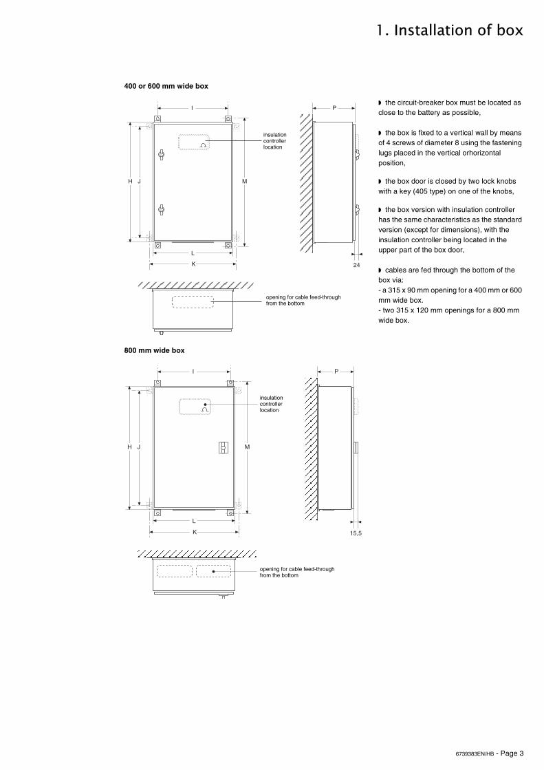
400 or 600 mm wide box
◗ the circuit-breaker box must be located as close to the battery as possible,
◗ the box is fixed to a vertical wall by means of 4 screws of diameter 8 using the fastening lugs placed in the vertical orhorizontal position,
◗ the box door is closed by two lock knobs with a key (405 type) on one of the knobs,
◗ the box version with insulation controller has the same characteristics as the standard version (except for dimensions), with the insulation controller being located in the upper part of the box door,
◗ cables are fed through the bottom of the box via:- a 315 x 90 mm opening for a 400 mm or 600 mm wide box.- two 315 x 120 mm openings for a 800 mm wide box.
800 mm wide box
�
��
�
���
�
insulation
opening for cable feed-through
controller location
from the bottom
�
���
�
�
���
insulation controller location
opening for cable feed-throughfrom the bottom

6739383EN/HB - Page 4
2. Characteristics of box
◗ the characteristics of the box indicated in the tables below are valid for a linear load charge with power factor of 0.8 and a minimum battery voltage set to 335 V on the inverter side (340 V on the battery side),◗ the recommended cable cross-sections are applicable to U1000R02V type copper conductors. They are calculated in relation to permissible temperature rises and take into account a maximum line voltage drop of 1 % for a maximum cable length of 25 m. For greater cable lengths, cross-sections will be chosen to keep the voltage drop within 1 %.
Note : the battery circuit breaker box for a 400 kVA UPS includes a battery current smoothing inductor (for 40 to 300 kVA and 500 to 600 kVA inverters, this inductor is in the rectifier-inverter cabinet).
2.1 Mechanical characteristics of boxBattery backup time less or equal to 10 mn
Battery backup time more than 10 mn
UPS
rated power in kVA
Box without insulation monitor Box with insulation monitor Max. cable cross- section in mm
2
Dimensions in mm weight in kg
Dimensions in mm weight in kg
H L P M I K J H L P M I K J
20 600 400 200 658 350 458 550 15 600 400 200 658 350 458 550 17 35
30 600 400 200 658 350 458 550 15 600 400 200 658 350 458 550 17 35
40 600 400 200 658 350 458 550 15 600 400 200 658 350 458 550 17 35
50 600 400 200 658 350 458 550 15 600 400 200 658 350 458 550 17 35
60 600 400 200 658 350 458 550 15 600 400 200 658 350 458 550 17 70
80 600 400 200 658 350 458 550 15 600 400 200 658 350 458 550 17 95
100 600 400 200 658 350 458 550 15 600 400 200 658 350 458 550 17 2 x 50
120 600 400 200 658 350 458 550 15 600 400 200 658 350 458 550 17 2 x 70
160 600 400 200 658 350 458 550 15 600 400 200 658 350 458 550 17 2 x 95
200 800 600 250 858 550 658 750 35 800 600 250 858 550 658 750 37 2 x 95
250 800 600 250 858 550 658 750 35 800 600 250 858 550 658 750 37 2 x 120
300 800 600 250 858 550 658 750 35 800 600 250 858 550 658 750 37 2 x 120
UPS
rated power in kVA
Box without insulation monitor Box with insulation monitor Max. cable cross- section in mm
2
Dimensions in mm weight in kg
Dimensions in mm weight in kg
H L P M I K J H L P M I K J
20 600 400 200 658 350 458 550 15 600 400 200 658 350 458 550 17 35
30 600 400 200 658 350 458 550 15 600 400 200 658 350 458 550 17 35
40 600 400 200 658 350 458 550 15 600 400 200 658 350 458 550 17 35
50 600 400 200 658 350 458 550 15 600 400 200 658 350 458 550 17 70
60 600 400 200 658 350 458 550 15 600 400 200 658 350 458 550 17 70
80 600 400 200 658 350 458 550 15 600 400 200 658 350 458 550 17 95
100 800 600 250 858 550 658 750 35 800 600 250 858 550 658 750 37 2 x 50
120 800 600 250 858 550 658 750 35 800 600 250 858 550 658 750 37 2 x 70
160 800 600 250 858 550 658 750 35 800 600 250 858 550 658 750 37 2 x 95
200 800 600 250 858 550 658 750 35 800 600 250 858 550 658 750 37 2 x 95
250 800 600 250 858 550 658 750 35 800 600 250 858 550 658 750 37 2 x 120
300 1000 800 303 1058 750 858 950 74 1000 800 303 1058 750 858 950 76 2 x 120
6739383EN/HB - Page 5
2. Characteristics of box
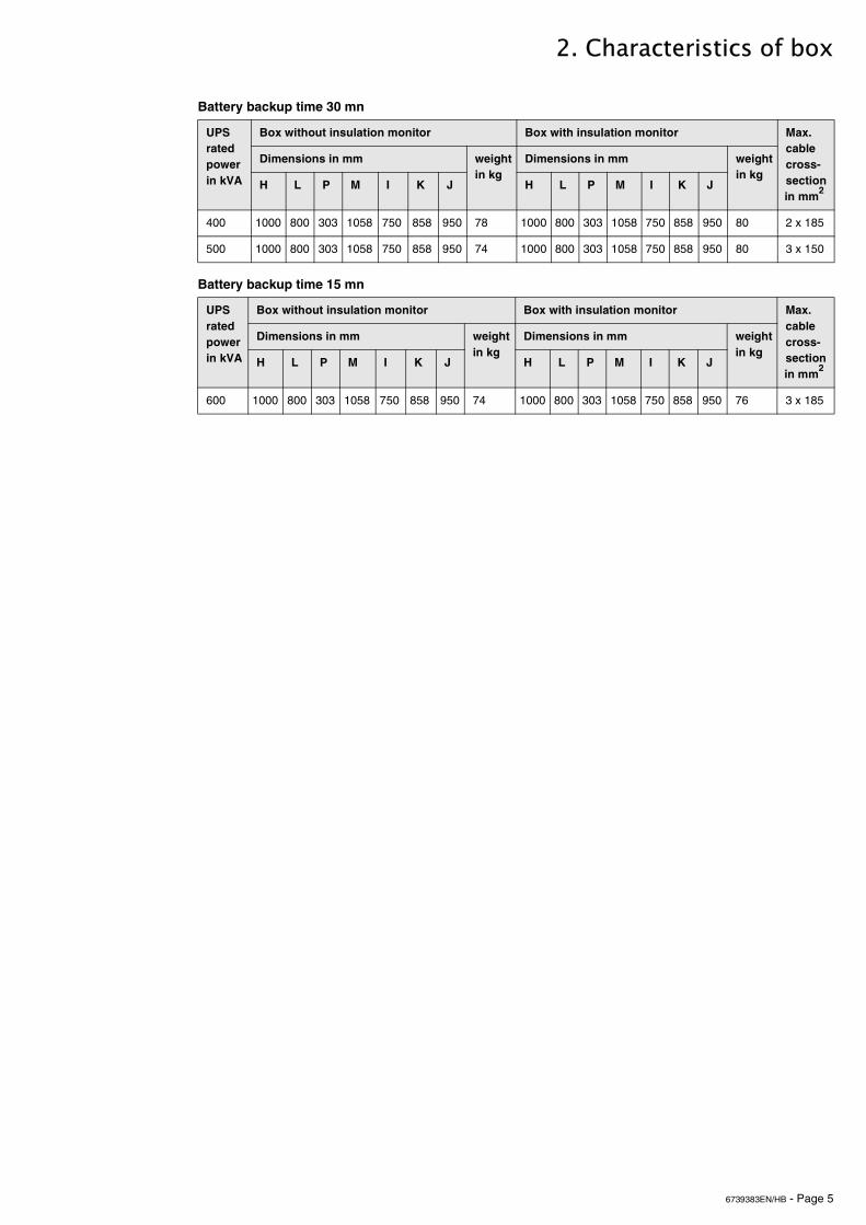
Battery backup time 30 mn
Battery backup time 15 mn
UPS
rated power in kVA
Box without insulation monitor Box with insulation monitor Max. cable cross- section in mm
2
Dimensions in mm weight in kg
Dimensions in mm weight in kg
H L P M I K J H L P M I K J
400 1000 800 303 1058 750 858 950 78 1000 800 303 1058 750 858 950 80 2 x 185
500 1000 800 303 1058 750 858 950 74 1000 800 303 1058 750 858 950 80 3 x 150
UPS
rated power in kVA
Box without insulation monitor Box with insulation monitor Max. cable cross- section in mm
2
Dimensions in mm weight in kg
Dimensions in mm weight in kg
H L P M I K J H L P M I K J
600 1000 800 303 1058 750 858 950 74 1000 800 303 1058 750 858 950 76 3 x 185

6739383EN/HB - Page 6
2. Characteristics of box
2.2 Electrical characteristics of boxBox can be equipped with Schneider NS, NSX or T6N circuit-breaker range:
NS circuit-breakers
(1) For other values, consult the after sales department or your local agency.
UPS rated power inkVA
Maximum battery back-up times at rated power (1)
QF1 circuit-breaker
Type Release Magnetic setting
thermal setting
20 10 mn NS 100 TM100D 800 A 1
> 10 mn NS 100 TM100D 800 A 1
30 10 mn NS 100 TM100D 800 A 1
> 10 mn NS 100 TM100D 800 A 1
40 10 mn NS 100 TM100D 800 A 1
> 10 mn NS160 TM160D 800 A 1
50 10 mn NS 100 TM100D 800 A 1
> 10 mn NS160 TM160D 800 A 1
60 10 mn NS160 TM160D 800 A 1
> 10 mn NS160 TM160D 800 A 1
80 10 mn NS160 TM160D 1250 A 1
> 10 mn NS250 TM250D 1250 A 1
100 10 mn NS250 TM250D 1250 A 1
> 10 mn NS400 MP1 800 A -
120 10 mn NS250 TM250D 1250 A 1
> 10 mn NS400 MP1 800 A -
160 10 mn NS250 TM250D 1250 A 1
> 10 mn NS400 MP1 800 A -
200 10 mn NS400 MP1 800 A -
> 10 mn NS630 MP1 800 A -
250 10 mn NS400 MP1 1000 A -
> 10 mn NS630 MP1 1000 A -
300 10 mn NS630 MP1 1000 A -

6739383EN/HB - Page 7
2. Characteristics of box
NSX or T6N circuit-breakers
(1) For other values, consult the after sales department or your local agency.
(2) Two poles in parallel by polarity, empacity x 2..
UPS rated power inkVA
Maximum battery back-up times at rated power(1)
QF1 circuit-breaker
Type Release Magnetic setting
thermal setting
20 10 mn NSX 100S DC TM100DC 800 A 1
> 10 mn NSX 100S DC TM100DC 800 A 1
30 10 mn NSX 100S DC TM100DC 800 A 1
> 10 mn NSX 100S DC TM100DC 800 A 1
40 10 mn NSX 100S DC TM100DC 800 A 1
> 10 mn NSX 160S DC TM160DC 800 A 1
50 10 mn NSX 100S DC TM100DC 800 A 1
> 10 mn NSX 160S DC TM160DC 800 A 1
60 10 mn NSX 160S DC TM160DC 800 A 1
> 10 mn NSX 160S DC TM160DC 800 A 1
80 10 mn NSX 160S DC TM160DC 1250 A 1
> 10 mn NSX 250S DC TM250DC 1250 A 1
100 10 mn NSX 250S DC TM250DC 1250 A 1
> 10 mn NSX 400S DC MP1 800 A -
120 10 mn NSX 250S DC TM250DC 1250 A 1
> 10 mn NSX 400S DC MP1 800 A -
160 10 mn NSX 250S DC TM250DC 1250 A 1
> 10 mn NSX 400S DC MP1 800 A -
200 10 mn NSX 400S DC MP1 1000 A -
> 10 mn NSX 630S DC MP1 1000 A -
250 10 mn NSX 400S DC MP1 1000 A -
> 10 mn NSX 630S DC MP1 1000 A -
300 10 mn NSX 630S DC MP1 1000 A -
> 10 mn T6N 800 4P TMA 800 A 4000 A(2) 560 A(2)
400 30 mn T6N 800 4P TMA 800 A 4000 A(2) 560 A(2)
500 30 mn T6N 800 4P TMA 800 A 4000 A(2) 680 A(2)
600 15 mn T6N 800 4P TMA 800 A 4000 A(2) 800 A(2)

6739383EN/HB - Page 8
3. Connection
3.1 Connection points
400 or 600 mm wide box
UPS rated power in kVA
Autonomy To UPS To battery To earth
Copper terminal in mm
Hole diameter in mm
Copper terminal in mm
Hole diameter in mm
Copper terminal in mm
threaded rod diameter in mm
20 All 25 x 5 8.2 25 x 5 8.2 50 x 5 8
30 All 25 x 5 8.2 25 x 5 8.2 50 x 5 8
40 All 25 x 5 8.2 25 x 5 8.2 50 x 5 8
50 All 25 x 5 8.2 25 x 5 8.2 50 x 5 8
60 All 25 x 5 8.2 25 x 5 8.2 50 x 5 8
80 All 25 x 5 8.2 25 x 5 8.2 50 x 5 8
100 10 mn 25 x 5 8.2 25 x 5 8.2 50 x 5 8
> 10 mn 32 x 8 12.2 32 x 10 12.2 50 x 5 8
120 10 mn 25 x 5 8.2 25 x 5 8.2 50 x 5 8
> 10 mn 32 x 8 12.2 32 x 10 12.2 50 x 5 8
160 10 mn 25 x 5 8.2 25 x 5 8.2 50 x 5 8
> 10 mn 32 x 8 12.2 32 x 10 12.2 50 x 5 8
200 All 32 x 8 12.2 32 x 10 12.2 50 x 5 8
250 All 32 x 8 12.2 32 x 10 12.2 50 x 5 8
300 10 mn 32 x 8 12.2 32 x 10 12.2 50 x 5 8
�
�� ��
��
�� ���
�
�
��
����������
��������
�������������
door openview AAbox with

6739383EN/HB - Page 9
3. Connection
800 mm wide box
UPS rated power in kVA
Autonomy To UPS To battery To earth
Copper terminal in mm
Hole diameter in mm
Copper terminal in mm
Hole diameter in mm
Copper terminal in mm
threaded rod diameter in mm
300 > 10 mn 50 x 10 3 x 12.2 125 x 5 3 x 12.2 50 x 8 3 x 12.2
400 30 mn 50 x 10 3 x 12.2 125 x 5 3 x 12.2 50 x 8 3 x 12.2
500 30 mn 50 x 16 3 x 12.2 125 x 8 3 x 12.2 50 x 8 3 x 12.2
600 15 mn 50 x 16 3 x 12.2 125 x 8 3 x 12.2 50 x 8 3 x 12.2
(1) only for an inverter with a power rating of 400 and 500 kVA.
�
�
�� ��
��
��
�����
����
�
To
Auxiliaries
to UPS
box with view AA
cabinet
battery
door open

6739383EN/HB - Page 10
3. Connection
3.2 Connection diagrams
Connection for box without insulation monitor
400 or 600 mm wide box
◗ the cross-section of the power cables is given in the tables in the section entitled "characteristics of box";◗ recommended cross-section of auxiliary conductors: 1 mm2 (terminal acceptance capacity: 2.5 mm2);◗ make sure that the auxiliary conductors and power cables do not follow the same path;◗ power cables and auxiliary conductors are not supplied.
Important : leave the QF1 circuit-breaker in "off" position until the UPS has been commissioned.
MGE™ Galaxy™ 5000 / 5500 :
MGE™ Galaxy™ PW :
(1) See MGE™ Galaxy™ PW installation manual.(2) strap or one of the contacts of the emergency stop button, if any.
�� ��
� � �
� � ��
�� ��
��������� !�"#�#�$%�$��%���& ��%#�%'#������(��
����#!!#$)*��+�'$,��-�.��)��%�#.
���#$-�����
�������� %#�%'#������(��
�����/#$�.�.�%(
���������������������������
��&��������&��6���������
��
�� ��
� � � � 0
���
�� ��
To battery
QF1 battery
position QF1 tripping:
XR1
to UPSbattery
to terminals 7 and 8 of the XR3 connector
contact of QF1 circuit-breaker
24V under-voltage coil
circuit-breaker
circuit-breakerbox
terminalblock
on the remote relay board (1).
to terminals 2 and 3 of the XR3 connectoron the remote board relay board (1).

6739383EN/HB - Page 11
3. Connection
800 mm wide box
◗ the cross-section of the power cables is given in the tables in the section entitled "characteristics of box";◗ recommended cross-section of auxiliary conductors: 1 mm2 (terminal acceptance capacity: 2.5 mm2);◗ make sure that the auxiliary conductors and power cables do not follow the same path;◗ power cables and auxiliary conductors are not supplied.
Important : leave the QF1 circuit-breaker in "off" position until the UPS has been commissioned.
MGE™ Galaxy™ 6000 :
(1) see MGE™ Galaxy™ 6000 installation manual.(2) strap or one of the contacts of the emergency stop button, if any.
MGE™ Galaxy™ 6000 :
(1) see MGE™ Galaxy™ 6000 installation manual.(2) strap or one of the contacts of the emergency stop button, if any.(3) only for an inverter with a power rating of 400 and 500 kVA.
�� ��
� � � � 0
���
�� ��
�� ��
� � � � 0
���
�� ��
to terminals 11 and 12 of the XR3 connector
to terminals 7 and 8 of the XR3 connector
To battery
QF1 battery
position QF1 tripping:
XR1
to UPSbattery
contact of QF1 circuit-breaker
24V under-voltage coil
circuit-breaker
circuit-breakerbox
terminalblock
on the remote relay board (1).
on the remote relay board (1).
� � � � 0
���
�� ��
�� ��
�����
to terminals 11 and 12 of the XR3 connector
to terminals 7 and 8 of the XR3 connector
To battery
QF1 battery
positionQF1 tripping:
XR1
to UPSbattery
contact of QF1 circuit-breaker
24V under-voltage coil
circuit-breaker
circuit-breakerbox
terminalblock
on the remote relay board (1).
on the remote relay board (1).

6739383EN/HB - Page 12
3. Connection
Connection for box with insulation monitor
400 or 600 wide box
◗ the cross-section of the power cables is given in the tables in the section entitled "characteristics of box";◗ recommended cross-section of auxiliary conductors: 1 mm2 (terminal acceptance capacity: 2.5 mm2);◗ make sure that the auxiliary conductors and power cables do not follow the same path;◗ power cables and auxiliary conductors are not supplied.
Important : leave the QF1 circuit-breaker in "off" position until the UPS has been commissioned.
MGE™ Galaxy™ 5000 / 5500 :
(1) see MGE™ Galaxy™ 5000 installation manual or MGE™ Galaxy™ 5500 installation manual.(2) strap or one of the contacts of the emergency stop button, if any.
��
� � ����1 2 3
240
� 3 �
� � �
�
���)�
+#)#.�5/6���
�
��
�� ��
��&��������&��6��������
!�7���"'!!. '$#�
#$"'.��#�$�&�'.�
����5��#$"'.��#�$�%#�%'#������(���&��8�$��/�.�"�'�%��#$��5� ���%��#$���"���&#)'����$�$�9��!�)��
��
��������� !�"#�#�$%�$��%���& ��%#�%'#������(��
����#!!#$)*��+�'$,��-�.��)��%�#.
���#$-�����
�������� %#�%'#������(��
�����/#$�.�.�%(
���������������������������
������/#$�.�.�%(
earth

6739383EN/HB - Page 13
3. Connection
MGE™ Galaxy™ PW :
(1) see MGE™ Galaxy™ PW installation manual.(2) strap or one of the contacts of the emergency stop button, if any.
��
� � � � 0���1 2 3
240
� 3 �
� � �
�
���)�
+#)#.�5/6���
�
��
���
�� ��
QF1 battery
to UPS
battery
to battery
power supply unit
XR2
insulation fault
to terminal 1 of the XM5 connector and
earth
circuit-breaker
circuit-breaker box
terminalblock
positionQF1 tripping:contact of
QF1 circuit-breaker
24V under-voltage coil
Mains 1 interphase voltage (380V, 400V or 415V):
terminal 2 of XM7 connector :- from UPS cabinet ETOI board (PW 40-60 kVA) or- from UPS cabinet RELI board (PW 80-200 kVA)
to terminals 7 and 8 of the XR3 connectoron the remote relay board (1).
to terminals 2 and 3 of the XR3 connectoron the remote board relay board (1).
XR1terminalblock

6739383EN/HB - Page 14
3. Connection
MGE™ Galaxy™ 6000 :
(1) see MGE™ Galaxy™ 6000 installation manual.(2) strap or one of the contacts of the emergency stop button, if any.
��
� � � � 0���1 2 3
240
� 3 �
� � �
�
���)�
+#)#.�5/6���
�
��
���
�� ��
earth
to terminals 11 and 12 of the XR3 connector
to terminals 7 and 8 of the XR3 connector
on the remote relay board (1).
on the remote relay board (1).
QF1 battery
to UPS
battery
to battery
power supply unit
XR2
insulation fault
circuit-breaker
circuit-breaker box
terminalblock
positionQF1 tripping:contact of
QF1 circuit-breaker
24V under-voltage coil
Mains 1 interphase voltage (380V, 400V or 415V):- to terminal 1 of the XM205 connector and terminal 2 of XM206 connector from UPS cabinet board RFIZ (unitary UPS)- to terminal 1 of the XM5 connector and terminal 2 of XM7 connector from UPS cabinet board RELI (modular UPS)
XR1terminalblock

6739383EN/HB - Page 15
3. Connection
800 mm wide box
◗ the cross-section of the power cables is given in the tables in the section entitled "characteristics of box";◗ recommended cross-section of auxiliary conductors: 1 mm2 (terminal acceptance capacity: 2.5 mm2);◗ make sure that the auxiliary conductors and power cables do not follow the same path;◗ power cables and auxiliary conductors are not supplied.
Important : leave the QF1 circuit-breaker in "off" position until the UPS has been commissioned.
MGE™ Galaxy™ 6000 :
(1) see MGE™ Galaxy™ 6000 installation manual.(2) strap or one of the contacts of the emergency stop button, if any.(3) only for an inverter with a power rating of 400 and 500 kVA.
� � � � 0���1 2 3
240
� 3 �
� � �
�
��
+#)#.�5/6���
�
���
�� ��
�� ��
�����
earth
to terminals 11 and 12 of the XR3 connector
to terminals 7 and 8 of the XR3 connector
on the remote relay board (1).
on the remote relay board (1).
QF1 battery
to UPS
battery
to battery
power supply unit
XR2
insulation fault
circuit-breaker
circuit-breaker box
terminalblock
QF1 tripping:contact of QF1 circuit-breaker
24V under-voltage coil
Mains 1 interphase voltage (380V, 400Vor 415V):- to terminal 1 of the XM205 connector and terminal 2 of XM206 connector from UPS cabinet board RFIZ (unitary UPS)- to terminal 1 of the XM5 connector and terminal 2 of XM7 connector from UPS cabinet board RELI (modular UPS)
XR1terminalblock

6739383EN/HB - Page 16
3. Connection
3.3 Auxiliary box connections
MGE™Galaxy™ 5000 / 5500 cabinets
���
����
���
����
���
����
���
����
to terminals1-2-3-4 ofQF1 circuit-breaker
To terminals 1-2 of box
Insulation circuit-breaker
To insulationcircuit-breaker

6739383EN/HB - Page 17
3. Connection
MGE™Galaxy™ PW cabinets
�����������
������������
�� ���
���������
����
���
�������
����
�������������
�� ��� �������
�������
�� ��� �������
������������� �������
����������
ETO board
RELI board
RELI board

6739383EN/HB - Page 18
3. Connection
MGE™Galaxy™ 6000 cabinets
160 to 200 kVA modular cabinet
Carte RELICarte RELI
�� ��� �������
terminal 1 XM5 terminal 2 XM7
RELI board
mains 1battery
cable tie bar
mains 2 load
to terminals 1 and 2 of XR2 terminal blockof battery circuit-breakerbox (version with controller)

6739383EN/HB - Page 19
3. Connection
160 to 400 kVA unitary cabinet
500 kVA unitary cabinet
�� ���� ������
terminal 1 terminal 2
RFIZ board
mains 1 battery
tie cable bar
mains 2 load
XM205 XM206
to terminals 1 and 2 of XR2 terminal block of battery circuit-breaker box (version with controller)
������������ terminal 1
terminal 2
RFIZ board
mains 1battery mains 2 load
XM205
XM206
to terminals 1 and 2 of XR2 terminal block of battery circuit-breaker box (version with controller)

6739383EN/HB - Page 20
3. Connection
600 kVA unitary cabinet
�:
terminal 1 terminal 2
RFIZ board
réseau 1 battery
cable tie bar
XM205 XM206
to terminals 1 and 2 of XR2 terminal block of battery circuit-breaker box (version with controller)