basic requirements, planning and installation, tv
TRANSCRIPT

TRIAX® technical appendix Basic requirements, Planning and installation, TV standards, Frequency, Channels, etc.
12 Side lobe
Main lobe
Ang
le o
f acc
epta
nce
-3 dB
rU
Average of 1 and 2
vU

2
Reliability is our business. It’s what we stand for.
For nearly 70 years, TRIAX has strived to be your preferred partner for all your connectivity needs. We’re proud to provide reliable solutions for the present, while connecting our customers to the future.
At the forefront of technological trends and developments, we’re with you each step of the way, from installing home connections and business critical hospitality solutions, to realising complex, large scale integrations.
Ready for any job at hand, our products are available individually or as part of tailor-made
solutions. From aerials and dishes, to headends, outlets, cables and beyond – we make connectivity easy, ensuring you live up to your own customer promises.
Rest assured that at TRIAX, reliability and innovation run through the core of everything we do, from product development to our friendly, efficient service and support.
So enjoy browsing through this catalogue for an overview of our full product range. And of course, we’re always just a phone call away for more inspiration towards your next solution.
Contact TRIAX To place an order or consult one of our experts, contact us via: Phone: +45 76 82 22 00e-mail: [email protected] Or pay us a visit online at www.triax.com, where you’ll find a wealth of further material about our products and solutions.

PB 3
Technical appendix
Introduction terrestrial aerials 4-5
Basic technical requirements 6
Technical data in the catalogue 7
Planning and installation 8-9
Earthing and equipotential 10
Frequency range of waves 10
TV standards 10
Frequency range and channels 11
Channels and frequencies 12
Carrier frequencies 12
Analogue colour and broadcasting 13
Signal level: mV to dBµV 14
Signal level: dBm to mW to dBm 14
TRIAX® technical appendixTriax Main Catalogue

4 5
Television antennas for DVB-TDVB-T reception is possible with any antenna that is suitable for the related frequency band and polari zation. In the catalogue all antennas suitable for the reception of DVB-T signals in VHF III and UHF IV/V bands are marked with the DVB logo .
Omnidirectional receptionThe omnidirectional radio antenna has approximately the same sensitivity for all directions and can only be recommended for well supplied reception areas.
Directional receptionThe directional antenna receives signals from one main direction better than omnidirectional antennas, but has poorer reception of signals from other directions. A directional antenna is absolutely necessary for areas where signals are weak, or in areas where a particular weak transmitter is to be received.
AntennasStereo signals can be received using any FM anten-na. Because, however, a higher signal level and greater freedom from reflection are needed for clear stereo reception than for mono reception, it is usually necessary to use a directional antenna.
Terrestrial aerials Introduction
12 Side lobe
Main lobe
Ang
le o
f acc
epta
nce
-3 dB
rU
Average of 1 and 2
vU
Antennas are suitable for the reception of digital terestrial signals (DVB-T)
Radiation pattern – The most important terms
GainRatio of an antenna’s reception power in its main receiving direction to receive power of a l/2 dipole at the same installation site (logarithmic measure expressed in dB). Angle of acceptanceAngular aperture of the major lobe between the points where the gain is lower by 3 dB than its maximum value. Major lobeSection of the radiation pattern in the direction of the maximum gain. Side lobeLateral and rearward lobe-shaped sections of the radiation pattern that have a lower gain than in the main receiving direction.
Front to back ratio*Ratio of the voltage Uv in the main receiving direction to an average Ur generated on the basis of the voltages of the side lobe 2 in the back direction (180°) and of the larger side lobe 1 in the rear sector (90°-270°) (logarithmic measure expressed in dB).
* CorrespondingtoadefinitionbytheTechnical Commission of the “Receiving Antennas” association in ZVEI

4 5
1.0 m
2.8 m
0.6 m
4) TRIAX TD 88 dish
3) UNIX 52
2) VHF ch. 8 - 8 elem.
Mast Ø42 mm
2.0 m
3.0 m
1) FM Omni
1/6
The sum of the moments resulting from the intrinsic moment of the mast and the bending moments caused by the mount ed antennas must not exceed the maximum permitted bending moments of the mast itself. The bending moment caused by an antenna is calculated by the following formula: Wind load (N) x distance (m) = bending moment (Nm)
The distance and bending moment refer to the top clamping point. Bending moments in excess of 1650 Nm require proof of structural stability. Wind load x distance = bending moment 1) 16 N x 3,6 m = 57.6 Nm2) 56 N x 2,8 m = 156.8 Nm3) 96 N x 2,0 m = 192,0 Nm4) 619 N x 1 m = 619,0 NmTotal bending moment of the antennas 1025,4 Nm The total bending moment for the antenna at 1025.4 Nm is less than the usable bending moment for the antenna to be mounted of 1250 Nm. Thereforetheintendedconfigurationispermitted!
In accordance with DIN EN 50083-1 the clamped length of the mast must be at least 1/6 of the mast length
Mast calculation designed for superior TV reception

6 7
All equipment and components in this catalogue meet, unless otherwise stated, the European standards for “Cable networks for television signals, sound signals and interactive services” from the standardisation organisation CENELEC, which have been adopted in national versions.
EN 50083-1 Safety requirementsEN 50083-1/A1EN 50083-1/A2EN 50083-2 Electromagnetic compatibility (EMC) of equipment
The equipment conforms to the uniform European “EMC directive” in accordance with legal requirements. For the majority of the product groups in this catalogue, EN 50083-2 is relevant. In relation to the “Low voltage directive”. EN 60065 is the basis to which reference is made in EN 50083-1 “Safety requirements”. The CE marking for products in relation to EMC and the low voltage directive is based on these standards. In addition, CENELEC committee TC 209 has ratified European standards for equipment and system requirements for “Cable networks for television signals, sound signals and interactive services”.
EN 50083-3 Active broadband equipment for coaxial cable networksEN 50083-4 Passive broadband equipment for coaxial cable networksEN 50083-5 Headend equipmentEN 50083-6 Optical equipmentEN 50083-7 System requirementsEN 50083-8 Electromagnetic compatibility of cable networksEN 50083-9 Interfaces for CATV/SMATV headends and similar professional equipment for DVB/MPEG-2 transport streamsEN 50083-10 System performance for return paths
The system and equipment requirements are matched to each other in such a way that the minimum requirements for signal quality at the subscriber’s outlet can be met with a minimum of technical effort. In addition, requirements that result from use of both analogue and digital signal transmission have also been taken into account. The EN 50083 standards provide the network operator, planner and installer with concrete guidelines for network design and selection of appropriate network components. TRIAX network components are developed to these standards and are marked in the catalogue by the relevant EN standard. The equipment standards (EN 50083 Parts 3...6) include fulfillment of the safety and EMC requirements (EN 50083 Parts 1 + 2).
The legally required CE marking for antenna and telecommunication products refers to adherence to electromagnetic compatibility (EMC) limits and, from 1 Jan 1997, to adherence to the low voltage directive.
The CE marking does not therefore imply fulfilment of the product and system requirements according to EN 50083- 3...-10. For this reason Triax indicates compliance with these basic requirements on equipment (EN 50083-3...6) by explicitly noting the corresponding EN standard in the catalogue and in the operating instructions.
1.1 Marking of components for TV cable networks
With the CE marking Triax confirms the compliance of its products with the applicable EU directives (currently EMC and low voltage directives) as well as with the standards EN 50083-1, EN 50083-2 and EN 60065. For receivers the standards EN 55013, EN 55020 and EN 61000 are applied. The CE marking is placed on the product, on the packaging and/or included in the operating instructions. To prevent interference between TV cable networks and radio services, it is necessary to use components with sufficient shielding. Due to the varying conditions in European countries, the shielding rate was defined in the European standard EN 50083-2 in two stages, the high quality class A and class B with reduced shielding rate values. For compliance with the legal EMC requirements for TV cable networks, we expressly recommend the use of class A components, including connecting cables so marked for terminal equipment.
Protection class 2 according to IEC 60417-5172 for components with power connection 230 V ~.
1. Basic technical requirements
TRIAX® technical appendixTriax Main Catalogue

6 7
2. Technical data in the catalogue2.1. Characteristic impedanceUnless otherwise expressly mentioned, all technical data in the catalogue refer to a 75W impedance for RF connections.
2.2. Operating temperatureAll passive units in the catalogue can be used within an operating temperature range of –20 °C to +60 °C. The mains-operated units meet the requirements of the EN 60065 standard within the temperature range from –20 °C to +50 °C. Operability of these units is nevertheless also maintained fully in the temperature range from –20 °C to +60 °C. Individual units that deviate with regard to the above operating temperature range are specifically mentioned.
2.3. Mains voltageAll mains-operated units in the catalogue already meet the requirements of the IEC 60038 standard. with a rated voltage of 230 V~ +6% /–10%.
2.4. Wind loadFor antenna locations, safety regulations according to EN 50083-1 differentiate between two heights above ground (up to 20 m and above 20 m). They specify different dynamic pressure values for each height. q = 800 N/m2. and q = 1100 N/m2 respectively. The wind load values (horizontal and vertical) specified in this catalogue were determined using a dynamic pressure of q = 800 N/m2. If a value for q = 1100 N/m2 is needed. the value in the catalogue has to be multiplied by 1.37.
2.5. Permissible output level for active electronic equipmentSpecification of the permissible output level is made according to EN 50083-3 “Active broadband equipment for coaxial cable networks” for a signal-to-noise ratio of:
• IMD = 60 dB for amplifiers for AM, QAM and FM signals (in SMATV/MATV, broadband cable, CATV installations)• IMD = 35 dB for amplifiers for FM signals only
(satellite IF transmission)
Now that this measurement method is standard throughout Europe, this important parameter has become transparent and comparable. With the aid of this information, the network planner and installer are able to determine the optimum amplifier gain (refer also to the planning instructions) to maintain the required minimum signal-to-noise ratios for a given number of channels. This procedure provides considerable advantages wherever new networks with a minimum number of amplifiers (cost advantage) are planned or where over riding regulations apply to certain parts of the network. For example the permissible output level for a house connection amplifier to a house connection point is explicitlyspecifiedatCTB/CSO≥66dB. This means that the required signal quality (CTB/CSO≥57dBaccordingtoEN50083-7)canbe maintained up to the subscriber’s connection. Other permissible output levels are also given on the one hand for the CENELEC spacing (EN 50083-3) and on the other hand for full adjacent channel load of TV bands.
Maintaining the latter control limits allows for any channel load with analogue and digital TV signals (worst case: complete channel load with analogue and digital TV channels). Assigning only digital TV channels in the frequency range < 606 MHz makes it possible to raise the output level of the house connection amplifier by up to 2 dB.
TRIAX® technical appendixTriax Main Catalogue

8 9
3. Planning and installation instructions3.1. Permissible output level for house connection amplifiers, multiple band amplifiers, and postamplifiers
It is always recommended to carry out these calculations on a Windows PC using:
� AND by CDS Germany (www.cdsgmbh.de) � CACAO by PTE-software (www.ptesoftware.dk)
The following explanations can be an additional help for solving problems and for understanding the underlying relationships.
The permissible output level is dependent on: � The required signal-to-noise ratio CTB, CSO � The number of TV channels to be transmitted � The frequency distribution of the channels
The signals of the FM radio band can be treated as a single TV channel if their levels are 6-8 dB below the level of the TV chan-nels.ThefirstselectioncriterionisthenumberofTVchannels to be transmitted.
3.1.1Maximum number of TV channels: 10 (MATV systems)
� Determine the permissible output level from the technical data: for IMD2 (60dB 2nd order intermodulation products according to EN 50083-5), for IMR3 (60dB 3rd order intermodulation products according to EN 50083-5)
� Reduce the IMR3 value according to the number of channels
The smaller of the two output levels (with respect to IMD2. IMR3) is the permissible output level (dB(µV)) for a signal-to-interference ratio of IMD=60 dB.
3.1.2More than 10 TV channels (broadband cable. MATV. CATV)Inordertoobtainoptimalgainfromamplifierswithmanychannels loaded, it is necessary to use the permissible output levelsspecificallydefinedforeachsuchcase(foraCSOandCTB ratio of 60 dB) and a channel raster as close as possible toadefinedone.
3.1.3Approximate calculation for the permissible output level:
a) Permissible output level dependent on required CSO and CTB values that are different from catalogue values:
CSOQuestion: “How high is the permissible output level for a CSO value D a dB above the catalogue value (CSO = 60 dB)?”na1 = output level in dB(µV) for CSO = 60 dB (catalogue value)na2 = output level in dB(µV) for CSO = (60 + D a) dB
na2 = na1 - D a
i. e. on an increase in the CSO requirement by D a dB, the permissible output level is reduced by D a dB.
CTBQuestion: “How high is the permissible output level for a CTB value D a dB above the catalogue value (CTB = 60 dB)?”na3 = output level in dB(µV) for CTB = 60 dB (catalogue value)na4 = output level in dB(µV) for CTB = (60 + D) dB
na4 = na3 - D a/2
i. e. on an increase in the CTB requirement by d a dB, the permissible output level is reduced by D a/2 dB.
b) Permissible output level for channel loads deviating from catalogue specifications
The individual Triax operating instructions list the maximum permissible output level for a signal-to-interference ratio of 60 dB for three different channel spacings: - up to 450 MHz: 36 TV + 24 FM channels. - up to 606 MHz: 29 TV channels (“CENELEC raster“) - up to 862 MHz: 42 TV channels (“CENELEC raster“) Refer to “Channel spacing” table
These conditions are critical with respect to the development of non-linear distortion (CTB, CSO). For small deviations of the actual channel spacing from the standard ones, it is not necessary to reduce the output level shown in the operating instructions. For larger deviations, the following rules of thumb can help to obtain a rough approximation for the adjustment:
1. Select the catalogue values corresponding to the highest channel frequency.2. For a channel pattern with twice the number of channelsspecifiedinthecatalogue.reducethe output level by about 3 dB.
Table1: Level reduction as a function of the number of channels loaded
Number of Correction to the channel loads catalog value in dB 2 0 3 – 2 4 – 3 5 – 4 6 – 5 7 – 5.5 8 – 6 10 – 7
TRIAX® technical appendixTriax Main Catalogue
8 9
3. Planning and installation instructions- continued from last page
If the frequency band contains only one half of the number of channels (with constant channel spacing), it is possible toraisetheoutputlevelby3dB.Iftheconfigurationliessomewhere in between these extremes, it is possible to make a rough interpolation.
c) Maximum output level for frequency pre-compensation (line equaliser)A frequency pre-compensation value for example of 10 dB usingalineequaliserpermitsdrivingtheamplifier approximately 2 dB higher. This value can also be treated as output reserve. It should be noted, however, that the signal-to-interference ratio at low frequencies will deteriorate by the amount of compensation attenu ation. For extreme cases , optimisation by a planning specialist is therefore required.
d) Permissible output level when cascading amplifiersFor cascades, reduce the output level by 3 dB each time youdoublethenumberofcascadedamplifiers.
3.2. Radiated interference power and max. operating levelThe radiated interference power of an antenna system according to EN 50083-2 may not exceed:
� 20 dB(pW) = 39 dB(µV) at 75W in the frequency range 30-950 MHZ
� 43 dB(pW) = 62 dB(µV) at 75W in the frequency range 950-2500 MHz
Thus,inconjunctionwiththeshieldingratespecifiedfortheequipment, the maximum operating level is as follows:Maximum operating level =
� Shielding rate+ 39 dB(µV) (in the 30-950 MHz frequency range)
� Shielding rate + 62 dB(µV) (in the 950-2500 MHz frequency range)
3.3. Shielding rateThe passive TRIAX components in this catalogue meet as a minimum the shielding rates required by EN 50083-2. class B:
� 5-470 MHz 75 dB min � 470-950 MHz 65 dB min � 950-3000 MHz 50 dB min
Class A components meet the increased requirements of EN 50083-2
� 5-300 MHz 85 dB min � 300-470 MHz 80 dB min � 470-950 MHz 75 dB min � 950-3000 MHz 55 dB min
For active units, the class A marking also documents compliance with EN 50083-2.
3.4. Signal-to-noise ratio, noise factor
The signal-to-noise ratio is the ratio of the used signal power to the noise power expressed in decibels. The noise factordefinesbyhowmuchthesignal-tonoiseratioattheoutputofanactiveunit(e.g.amplifier)islessthanthesignal-to-noise ratio at the input.
The thermal noise level on a 75 W resistor amounts - for a bandwidth of 5 MHz (TV channel) and - for a temperature of 293 K to approximately 2 dB(µV).
The signal-to-noise ratio of the received signal is the decisive factor for the video quality of a TV set (see below). The signal-to-noise ratio at the output of an individual amplifier(forideal.i.e.noise-freeinputsignal)canbe determined as follows:
Operating level at the output � gain � noise factor � noise level
Example:Anamplifierwiththefollowingoutputparameters: 94 dB(µV) operating level, 21 dB gain, and 7 dB noise factor.The signal-to-noise ratio at the output of an individual amplifierwouldthenbe: 94 dBµV operating level – 21 dB set gain –7 dB noisefigure – 2 dBµV noise level = 64 dB s/n out
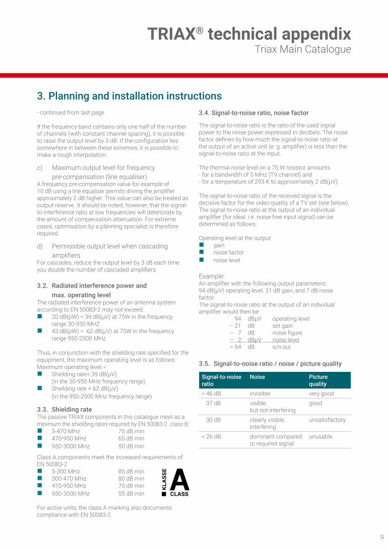
3.5. Signal-to-noise ratio / noise / picture quality
Signal-to-noiseratio
Noise Picture quality
> 46 dB invisible very good 37 dB visible,
but not interferinggood
30 dB clearly visible, interfering
unsatisfactory
< 26 dB dominant compared to required signal
unusable
TRIAX® technical appendixTriax Main Catalogue

10 11
4. Earthing and equipotential bonding cablesEN50083-1specifiesthefollowingearthingandequipotentialbondingcablesforantennasystems:
Earthing cables:Material Cross-section Ø Condition ExampleCopper > 16 mm2 > 4.6 mm bare or insulated KokaAluminium
Aluminium
> 25 mm2
> 50 mm2
> 5.7 mm
> 8.0 mm
bare (indoors only) or insulated (wrought) alloy
Steel wireSteel strip
- 2.5 x 20 mm
8.0 mm -
galvanisedgalvanised
--
Cable types: single conductor or multi-conductor,butnofinewires
Equipotential bonding cables:Material Cross-section Ø Condition ExampleCopper 4 mm2 2.3 mm bare or insulated Koka
Frequency ranges of radio wavesFrequencyrange
Int. abb. Abb. ModulationPicture/sound
Channelwidth
Channels Frequency Wave-length
Polarisation
Long wave LF L AM 9 kHz 2-4 150 - 285 kHz 2000 - 1050 m VMedium wave MF M AM 9 kHz 510 - 1605 kHz 590 - 187 m VShort wave HF K AM 9 kHz 3.95 - 26.1 MHz 76 - 11.5 m VBand I VHF F I AM FM 7 MHz 2-4 47 - 68 MHz 6.35 - 4.4 m H/VBand II (radio) VHF UKW FM 300 kHz 2-70 87.5 - 108 MHz 3.4 - 2.8 m HS-channels VHF USB AM FM 7 MHz S2 - S10 111 - 174 MHz 2.7 - 1.7 m -1)
Band III VHF F III AM FM 7 MHz 5-12 174 - 230 MHz 1.7 - 1.3 m H/VS-channels VHF OSB AM FM 7 MHz S11 - S20 230 - 300 MHz 1.3 - 1.0 m -1)
S-channels UHF ESB AM FM 8 MHz S21 - S38 302 - 446 MHz 99 - 68 cm -1)
Band IV UHF F IV AM FM 8 MHz 21-39 470 - 622 MHz 64 - 68 cm H/VBand V UHF F V AM FM 8 MHz 40-60 622 - 790 MHz 48 - 38 cm H/V
-1) in wideband installation
5. TV standards
1) Second audio carrier for dual or stereo operation
Standard No. of lines
Channel width(MHz)
Video bandwidth
(MHz)
Video/audio seperation
(MHz)
Vestigial sideband
(MHz)
Videomodulation
Audio modulation
B (CCIR) 625 7 5 + 5.5 (+5.742) 0.75 negative FM. FM1
D (OIRT) 625 8 6 + 6.5 0.75 negative FMG (CCIR) 625 8 5 + 5.5 (+5.742) 0.75 negative FM. FM1
H (B) 625 8 5 + 5.5 1.25 negative FMI (GB) 625 8 5.5 + 6.0 1.25 negative FMK (OIRT) 625 8 6 + 6.5 0.75 negative FMK1 (CCIR) 625 8 6 + 6.5 1.25 negative FML (F) 625 8 6 + 6.5 1.25 positive AMM (FCC) 525 6 4.2 + 4.5 0.75 negative FMN (South America) 625 6 4.2 + 4.5 0.75 negative FM
TRIAX® technical appendixTriax Main Catalogue

10 11
6. Frequency ranges and channel allocation
Channel number
Frequency range
Channel centre
Picture carrier
1st sound
Unit MHz MHz MHzReturn/datacommunication 4 - 30
Return/datacommunication 5 - 65
Return-TV R 1 14.75-21.75R 2 21.75-28.75
Band I 2 47 - 54 50.50 48.25 53.753 54 - 61 57.50 55.25 60.754 61 - 68 64.50 62.25 67.75
Data channel 70 - 75Band II / FM 2 - 70 87.5 - 108Digital-sound S 2 111 - 1181st channel S 3 118 - 125Lower S 4 125 - 132 128.50 126.25 131.75S-channels S 5 132 - 139 135.50 133.25 138.75
S 6 139 - 146 142.50 140.25 145.75USB S 7 146 - 153 149.50 147.25 152.75
S 8 153 - 160 156.50 154.25 159.75S 9 160 - 167 163.50 161.25 166.75S10 167 - 174 170.50 168.25 173.75
Band III 5 174 - 181 177.50 175.25 180.75TV/DAB 6 181 - 188 184.50 182.25 187.75
7 188 - 195 191.50 189.25 194.758 195 - 202 198.50 196.25 201.759 202 - 209 205.50 203.25 208.75
10 209 - 216 212.50 203.25 208.7511 216 - 223 219.50 217.25 222.7512 223 - 230 226.50 224.25 229.75
Upper S 11 230 - 237 233.50 231.25 236.75S-channels S 12 237 - 244 240.50 238.25 243.75
S 13 244 - 251 247.50 245.25 250.75S 14 251 - 258 254.50 252.25 257.75S 15 258 - 265 261.50 259.25 264.75S 16 265 - 272 268.50 266.25 271.75S 17 272 - 279 275.50 273.25 278.75S 18 279 - 286 282.50S 19 286 - 293 289.50 287.25S 20 293 - 300 296.50 294.25 299.75
S-channels S 21 302 - 310 306.00 303.25 308.75S 22 310 - 318 314.00 311.25 316.75S 23 318 - 326 322.00 319.25 324.75S 24 326 - 334 330.00 327.25 332.75S 25 334 - 342 338.00 335.25 340.75S 26 342 - 350 346.00 343.25 348.75S 27 350 - 358 354.00 351.25 356.75S 28 358 - 366 362.00 359.25 364.75S 29 366 - 374 370.00 367.25 372.75S 30 374 - 382 378.00 375.25 380.75S 31 382 - 390 386.00 383.25 388.75S 32 390 - 398 394.00 391.25 396.75S 33 398 - 406 402.00 399.25 404.75S 34 406 - 414 410.00 407.25 412.75S 35 414 - 422 418.00 415.25 420.75S 36 422 - 430 426.00 423.25 428.75S 37 430 - 438 434.00 431.25 436.75S 38 438 - 446 442.00 439.25 444.75
Channel number
Frequency range
Channel centre
Picture carrier
1st sound
Unit MHz MHz MHzBand IV 21 470 - 478 474.00 471.25 476.75
22 478 - 486 482.00 476.25 484.7523 486 - 494 490.00 487.25 492.7524 494 - 502 498.00 495.25 500.7525 502 - 510 506.00 503.25 508.7526 510 - 518 514.00 511.25 516.7527 518 - 526 522.00 519.25 524.7528 526 - 534 530.00 527.25 532.7529 534 - 542 538.00 535.25 540.7530 542 - 550 546.00 543.25 548.7531 550 - 558 554.00 551.25 556.7532 558 - 566 562.00 559.25 564.7533 566 - 574 570.00 567.25 572.7534 574 - 582 578.00 575.25 580.7535 582 - 590 586.00 583.25 588.7536 590 - 598 594.00 591.25 596.7537 598 - 606 602.00 599.25 604.7538 606 - 614 610.00 607.25 612.7539 614 - 622 618.00 615.25 618.75
Band V 40 622 - 630 626.00 623.25 626.7541 630 - 638 634.00 631.25 636.7542 638 - 646 642.00 639.25 644.7543 646 - 654 650.00 647.25 652.7544 654 - 662 658.00 655.25 660.7545 662 - 670 666.00 663.25 668.7546 670 - 678 674.00 671.25 676.7547 678 - 686 682.00 679.25 684.7548 686 - 694 690.00 687.25 692.7549 694 - 702 698.00 695.25 700.25
ECN/LTE 700 50 702 - 710 706.00 703.25 708.75Band V 51 710 - 718 714.00 711.25 716.75
52 718 - 726 722.00 719.25 724.7553 726 - 734 730.00 727.25 732.7554 734 - 742 738.00 735.25 740.7555 742 - 750 746.00 743.25 748.7556 750 - 758 754.00 751.25 756.7557 758 - 766 762.00 759.25 764.7558 766 - 774 770.00 767.25 772.7559 774 - 782 778.00 775.25 780.7560 782 - 790 786.00 783.25 788.75
ECN/LTE 800 61 790 - 798 794.00 791.25 796.75Band V 62 798 - 806 802.00 799.25 804.75
63 806 - 814 810.00 807.25 812.7564 814 - 822 818.00 815.25 820.7565 822 - 830 826.00 823.25 828.7566 830 - 838 834.00 831.25 836.7567 838 - 846 842.00 839.25 844.7568 846 - 854 850.00 847.25 852.7569 854 - 862 858.00 855.25 860.75
TRIAX® technical appendixTriax Main Catalogue

12 13
6. Channels and frequencies
Standard B. ItalyVHF I A 52.5-59.5 53.75 59.25 B 61-68 62.25 67.75 VHF II C 81-88 82.25 87.75 VHF III D 174-181 175.25 180.75 E 182.5- 189.5 183.75 189.25 F 191-198 192.25 197.75 G 200-207 201.25 206.75 H 209-216 210.25 215.75 H 1 216-223 217.25 222.75 H 2 223-230 224.25 229.75 Standard D. OIRT VHF I R I 48.5-56.5 49.75 56.25 R II 58-66 59.25 65.75 R III 76-84 77.25 83.75(VHF II) R IV 84-92 85.25 91.75 R V 92-100 93.25 99.75 s1 110-118 111.25 117.75 s2 118-126 119.23 125.75 s3 126-134 127.25 133.75 s4 134-142 135.25 141.75 s5 142-150 143.25 149.75 s6 150-158 151.25 157.75 s7 158-166 159.25 165.75 s8 166-174 167.25 173.75 (VHF III) R VI 174-182 175.25 181.75 R VII 182-190 183.25 189.75 R VIII 190-198 191.25 197.75 R IX 198-206 199.25 205.75 R X 206-214 207.25 213.75 R XI 214-222 215.25 221.75 R XII 222-230 223.25 229.75 s9 230-238 231.25 237.75 s10 238-246 239.25 245.75 s11 246-254 247.25 253.75 s12 254-262 255.25 261.75 s13 262-270 263.25 269.75 s14 270-278 271.25 277.75 s15 278-286 279.25 285.75 s16 286-294 287.25 293.75 s17 294-302 295.25 301.75 s18 302-310 303.25 309.75 s19 310-318 311.25 317.75 s20 318-326 319.25 325.75 s21 326-334 327.25 333.75 s22 334-342 335.25 341.75 s23 342-350 343.25 349.75 .. .............. .......... .......... s38 462-470 463.25 469.75
Standard D. ChinaVHF I 1 48.5-56.5 49.75 56.25 2 56.5-64.5 57.75 64.25 3 64.5-72.5 65.75 72.25 4 76.0-84.0 77.25 83.75 5 84.0-92.0 85.25 91.75VHF III 6 167-175 168.25 174.75 7 175-183 176.25 182.75 8 183-191 184.25 190.75 9 191-199 192.25 198.75 10 199-207 200.25 206.75 11 207-215 208.25 214.75 12 215-223 216.25 222.75 Standard I. Ireland VHF I I A 44.5-52.5 45.75 51.75 I B 52.5-60.5 53.75 59.75 I C 60.5-68. 5 61.75 67.75VHF III I D 174-182 175.25 181.25 I E 182-190 183.25 189.25 I F 190-198 191.25 197.25 I G 198-206 199.25 205.25 I H 206-214 207.25 213.25 I J 214-222 215.25 221.25 Standard L. France VHF I A 41.00-49.00 47.75 41.25 B 49.00-57.00 55.75 49.25 C 57.00-65.00 63.75 57.25 C 1 53.75-61.75 60.50 54.00 VHF III 5 174.75-182.75 176.00 182.50 6 182.75-190.75 184.00 190.50 7 190.75-198.75 192.00 198.50 8 198.75-206.75 200.00 206.50 9 206.75-214.75 208.00 214.50 10 214.75-222.75 216.00 222.50 Standard K1. (France)VHF III 4 174-182 175.25 181.75 5 182-190 183.25 189.75 6 190-198 191.25 197.75 7 198-206 199.25 205.75 8 206-214 207.25 213.75 9 214-222 215.25 221.75
Spec
. cha
nel
Spec
. cha
nel
Channel Channellimits(MHz)
Videocarrier(MHz)
Audiocarrier(MHz)
5.68
6.75
6.992
7 MHz channel raster
8 MHz channel raster
Picture Color 2. Sound
1. Sound
λ MHz1.25
7. Carrier frequencies for radio and TV channelsFrequencies of a TV-signal (Norm B. G/Pal)
7 MHz raster: FI. USB. F III. OSB
8 MHz raster: ESB. F IV. F V
TRIAX® technical appendixTriax Main Catalogue
Channel Channellimits(MHz)
Videocarrier(MHz)
Audiocarrier(MHz)

12 13
8. Analogue colour and broadcasting systems by countryCountry TV Colour
systemStereo Subtitles
Albania B/G PAL Argentina N PAL-N Australia B/G PAL FM-FM Teletext Austria B/G PAL FM-FM Teletext Azores (Portugal) B PAL Bahamas M NTSC Bahrain B PAL Barbados M NTSC Belgium B/G PAL Nicam Teletext Bermuda M NTSC Brazil M PAL-M MTS Bulgaria D SECAM Canada M NTSC MTS CC Canary Is B PAL China D PAL Colombia M NTSC Cyprus B PAL Czechsolvakia D/K SECAM/PAL Denmark B PAL Nicam Teletext Egypt B SECAM Faroe Islands (DK) B PAL Finland B/G PAL Nicam Teletext France E/L SECAM Teletext Gambia I PAL Germany B/G PAL FM-FM Teletext Germany (old East) B/G SECAM/PAL Gibraltar B PAL Greece B/G PAL Hong Kong I PAL Nicam Hungary B/G &
D/K PAL Nicam
(Budapest) Iceland B PAL India B PAL Indonesia B PAL Iran H SECAM Ireland I PAL Nicam Teletext Israel B/G PAL Nicam Teletext Italy B/G PAL FM/FM Teletext Jamaica N SECAM Japan M NTSC Matrix Jordan B PAL Kenya B PAL Korea M NTSC Luxembourg B/G PAL NICAM Teletext Madeira B PAL Madagascar B SECAM Malaysia B PAL Malta B/G PAL Mauritius B SECAM Mexico M NTSC MTS CC Monaco L/G SECAM/PAL Morocco B SECAM
Country TV Coloursystem
Stereo Subtitles
Netherlands B/G PAL FM-FM Teletext New Zealand B/G PAL Nicam Teletext North Korea D/K SECAM Norway B/G PAL Nicam Pakistan B PAL Paraguay N PAL Peru M NTSC Philipines M NTSC Poland D/K PAL Teletext Portugal B/G PAL Nicam Teletext Romania G PAL Russia D/K SECAM Saudi Arabia B SECAM Seychelles I PAL Singapore B PAL South Africa I PAL South Korea M NTSC Spain B/G PAL Nicam Teletext Sri Lanka B/G PAL Sweden B/G PAL Nicam Teletext Switzerland B/G PAL FM-FM Teletext Tahiti KI SECAM Taiwan M NTSC Thailand B PAL Trinidad M NTSC Tunisia B SECAM Turkey B PAL - Teletext United Arab Emirates B/G PAL United Kingdom I PAL Nicam Teletext Uruguay N PAL MTS USA M NTSC MTS CC Venezuela M NTSC Yugoslavia B/H PAL Zimbabwe B PAL
TRIAX® technical appendixTriax Main Catalogue

14 PB
Signal level - mV to dBµV
mV v/75 W dBµV20.0 8622.5 8725.0 8828.0 8931.5 9035.5 9140.0 9245.0 9350.0 9456.0 9563.0 9670.0 9780.0 9890.0 99100 100112 101125 102140 103160 104180 105200 106225 107250 108280 109315 110355 111400 112450 113500 114560 115630 116700 117800 118900 119
1000 1201120 1211250 1221400 1231600 1241800 1252000 1262250 1272500 1282800 129
mV v/75 W dBµV0.100 400.112 410.125 420.140 430.160 440.180 450.200 460.225 470.250 480.280 490.315 500.355 510.400 520.450 530.500 540.560 550.630 560.700 570.800 580.900 591.00 601.12 611.25 621.40 631.60 641.80 652.00 662.25 672.50 682.80 693.15 703.55 714.00 724.50 735.00 745.60 756.30 767.00 778.00 789.00 7910.0 8011.2 8112.5 8214.0 8316.0 8418.0 85
Voltage ratio in dB
*) Factor -dB dB *) Factor +dB1.0 0.0 1.0
0.95 0.5 1.060.89 1.0 1.120.84 1.5 1.190.8 2.0 1.25
0.75 2.5 1.330.71 3.0 1.410.67 3.5 1.50.63 4.0 1.60.60 4.5 1.670.56 5.0 1.780.53 5.5 1.880.50 6.0 2.00.47 6.5 2.120.45 7.0 2.240.42 7.5 2.370.4 8.0 2.5
0.38 8.5 2.660.35 9.0 2.820.33 9.5 3.000.32 10 3.160.28 11 3.550.25 12 4.000.22 13 4.50.2 14 5.00
0.18 15 5.620.16 16 6.30.14 17 7.1
0.125 18 8.00.11 19 8.90.10 20 10.0
0.089 21 10.00.08 22 12.5
0.071 23 14.10.063 24 16.00.056 25 17.80.050 26 20.00.045 27 22.40.04 28 25.0
0.035 29 28.20.032 30 31.60.028 31 35.50.025 32 400.022 33 450.020 34 500.018 35 560.016 36 630.014 37 71
0.0125 38 800.011 39 890.01 40 100
0.0056 45 1780.0032 50 3160.0018 55 5620.001 60 1000
*) The numbers are dB value calculated to times.Signal level is often stated in dBµV which is to be understood as the number of dB the signal exceeds 1µV.
9. Signal level - mV to dBµV 10. Power level dBm to mV to dBm
dBm mW dBm mW-20 0,01 -20,00 0,01-19 0,01 -16,99 0,02-18 0,02 -15,23 0,03-17 0,02 -13,98 0,04-16 0,03 -13,01 0,05-15 0,03 -12,22 0,06-14 0,04 -11,55 0,07-13 0,05 -10,97 0,08-12 0,06 -10,46 0,09-11 0,08 -10,00 0,1-10 0,10 -6,99 0,2-9 0,13 -5,23 0,3-8 0,16 -3,98 0,4-7 0,20 -3,01 0,5-6 0,25 -2,22 0,6-5 0,32 -1,55 0,7-4 0,40 -0,97 0,8-3 0,50 -0,46 0,9-2 0,63 -0,00 1-1 0,79 3,01 20 1,00 4,77 31 1,26 6,02 42 1,58 6,99 53 2,00 7,78 64 2,51 8,45 75 3,16 9,03 86 3,98 9,54 97 5,01 10,00 108 6,31 10,41 119 7,94 10,79 12
10 10,00 11,14 1311 12,59 11,46 1412 15,85 11,76 1513 19,95 12,04 1614 25,12 12,30 1715 31,62 12,55 1816 39,81 12,79 1917 50,12 13,01 2018 63,10 13,22 2119 79,43 13,42 2220 100,00 13,62 2321 125,89 13,80 2422 158,49 13,98 2523 199,53 14,15 2624 251,19 14,31 2725 316,23 14,47 2826 398,11 14,62 2927 501,19 14,77 30
TRIAX® technical appendixTriax Main Catalogue

15
Notes
15

16
Art. No. 891407
Contact
TRIAX is a global supplier of reliable, innovative products and solutions for the reception and distribution of video, audio and data signals.Our Products are used in homes, businesses and operator networks by broadcasters, satellite, cable and telecom operators.Our Solutions combine our hardware and software expertise to deliver value to hospitality and related markets, through a partner network of system integrators, large installers and operators. TRIAX’s headquarters, production and R&D base is in Denmark. With 9 international sales subsidiaries we operate in more than 60 distributor countries. The TRIAX team consists of 300 employees and is owned by Polaris Private Equity.
See www.triax.com for further info.
Copyright © 2016 TRIAX. All rights reserved. The TRIAX Logo and TRIAX, TRIAX Multimedia areregisteredtrademarksortrademarksoftheTRIAXCompanyoritsaffiliates. The Triax portfolio is constantly changing and growing so this catalogue cannot be complete at all times. Please refer to our website and your sales representative for an update.Allspecificationinthiscataloguesubjecttochangewithoutfurthernotice.
triax.com / contact
05-2
018A