basic hydraulics learning activity packet · did you notice that the flow rate is different when...
TRANSCRIPT

4
BASICHYDRAULICS
BASIC HYDRAULIC CIRCUITSBASIC HYDRAULIC CIRCUITS
LEARNINGACTIVITYPACKET
BB831-XA02XEN
TM

LEARNING ACTIVITY PACKET 2
BASIC HYDRAULIC CIRCUITS
INTRODUCTIONThis LAP will explore two new components: motors and needle valves. Both of
which are often used in hydraulic circuits.The first segment will continue to discuss hydraulic pumps, and the last segment will
explain the interpretation and creation of hydraulic schematics. These are important skills to know when working with fluid power.
ITEMS NEEDEDYou will need the following items in order to perform this LAP.Amatrol Supplied 1 85-BH Basic Hydraulic Training System 1 85-HPS Hydraulic Power Unit
School Supplied 1 Allen Wrench Set 1 Stopwatch 1 Measuring Container (1-5 gal./3.78-18.9 liters)
Shop Towels or Rags
BB831-XA02XEN BASIC HYDRAULIC CIRCUITSCopyright © 2010 Amatrol, Inc. 2
FIRST EDITION, LAP 2, REV. BAmatrol, AMNET, CIMSOFT, MCL, MINI-CIM, IST, ITC, VEST, and Technovate are trademarks or registered trademarks of Amatrol,Inc. All other brand and product names are trademarks or registered trademarks of their respective companies.Copyright © 2010, 2009 by AMATROL, INC.All rights Reserved. No part of this publication may be reproduced, translated, or transmitted in any form or by any means, electronic,optical, mechanical, or magnetic, including but not limited to photographing, photocopying, recording or any information storage andretrieval system, without written permission of the copyright owner.Amatrol,Inc., 2400 Centennial Blvd., Jeffersonville, IN 47130 USA, Ph 812-288-8285, FAX 812-283-1584 www.amatrol.com

TABLE OF CONTENTS
SEGMENT 1 PUMPS . . . . . . . . . . . . . . . . . . . . . . . . . . . . . . . . . . . . . . . . . . . . . . . . . . . . . . . 4OBJECTIVE 1 Define flow rate and explain how it can be measuredOBJECTIVE 2 Describe the operation of two types of flowmeters and give their schematic symbol
SKILL 1 Connect and read a flow meterActivity 1 Flowmeter accuracy
OBJECTIVE 3 Describe the operation of a fixed-displacement pump and give its schematic symbolActivity 2 Fixed-displacement pump operation
OBJECTIVE 4 Describe the operation of three types of fixed-displacement pumps and give an application of each
SEGMENT 2 NEEDLE VALVES . . . . . . . . . . . . . . . . . . . . . . . . . . . . . . . . . . . . . . . . . . . . . . . 23OBJECTIVE 5 Describe the main function of a needle valveOBJECTIVE 6 Describe the operation of a needle valve and give its schematic symbol
Activity 3 Needle valve operationSKILL 2 Connect and operate a needle valve to control the speed of an actuatorSKILL 3 Control the speed of an actuator using a manually-operated DCV
SEGMENT 3 BASIC MOTOR CIRCUITS. . . . . . . . . . . . . . . . . . . . . . . . . . . . . . . . . . . . . . . . . . 35OBJECTIVE 7 Describe the function of a hydraulic motor and give an applicationOBJECTIVE 8 Describe the operation of a hydraulic motor and give its schematic symbol
SKILL 4 Connect and operate a bi-directional hydraulic motor using a 3-position, manually-operated DCVOBJECTIVE 9 List three types of hydraulic motors and give an application of each
SEGMENT 4 HYDRAULIC SCHEMATICS . . . . . . . . . . . . . . . . . . . . . . . . . . . . . . . . . . . . . . . . . 51OBJECTIVE 10 Describe eight basic rules for drawing hydraulic schematics
SKILL 5 Draw a hydraulic schematic from the actual circuit connections on a pictorialSKILL 6 Draw a hydraulic circuit given a schematicSKILL 7 Design a multiple actuator hydraulic circuit
BB831-XA02XEN BASIC HYDRAULIC CIRCUITSCopyright © 2010 Amatrol, Inc. 3

SEGMENT 1
PUMPS
OBJECTIVE 1 DEFINE FLOW RATE AND EXPLAIN HOW ITCAN BE MEASURED
The flow rate of a fluid indicates the amount of fluid that flows pasta point in a certain amount of time. This amount can be measured as aweight or volume. In hydraulics, flow is most often measured by volume. The most common flow rate units of measure are gallons per minute(gpm) in the U.S. Customary system and liters per minute (lpm) in theS.I. metric system.
BB831-XA02XEN BASIC HYDRAULIC CIRCUITSCopyright © 2010 Amatrol, Inc. 4
POINT A
TIME FOR THEFLUID TO FLOWPAST POINT A
VOLUME OF FLUID
Figure 1. Volume Flow in a Tube
VOLUMETRIC FLOW RATE FORMULA
Flow Rate = Volume
Time
Where:
U.S. Customary Units
Flow Rate = Gallons per Minute (gpm)
S.I. Units
Flow Rate = Liters per Minute (lpm)

One way the flow rate in a system can be determined is bymeasuring the amount of time it takes to fill a container of knownvolume. For example, if the flow from a hydraulic pump fills a 5-literbucket in one minute, the pump’s flow rate is 5 liters per minute (5 lpm). This method can be very accurate but is messy and time consuming. Thepreferred method for measuring flow rate is a flowmeter, although thismethod is not as accurate as measuring with a stopwatch and a container.
OBJECTIVE 2 DESCRIBE THE OPERATION OF TWO TYPES OFFLOWMETERS AND GIVE THEIR SCHEMATIC SYMBOL
A flowmeter is a device that measures the flow rate of fluid.Flowmeters are useful tools for troubleshooting hydraulic systems. Theycan show that a pump is wearing out or that a line is blocked. They arealso used in the laboratory for testing.
The two common types of hydraulic flowmeters are the rotameterand the turbine-type flowmeter.
RotameterThe rotameter consists of a transparent tube which contains a
movable piston. The tube and piston are constructed so that the fluidflows through the tube and around the piston, as shown in figure 2. Theflow rate is determined by measuring the height to which the piston israised by the force of the fluid flow.
This type of flowmeter must be oriented in a vertical position and isusually rated for low pressures. This means it can only be used in a returnline.
BB831-XA02XEN BASIC HYDRAULIC CIRCUITSCopyright © 2010 Amatrol, Inc. 5

Another type of rotameter uses a spring against which the piston ispushed to indicate flow rate. This type of flowmeter can be oriented inany position. It is the type used in the 850 Series trainer.
BB831-XA02XEN BASIC HYDRAULIC CIRCUITSCopyright © 2010 Amatrol, Inc. 6
MOVABLEPISTON
FLUID PASSES THROUGHTHIS ANNULAR AREA
TAPERED GLASSMETERING TUBE
INLET
OUTLET
Figure 2. Rotameter

Turbine-Type FlowmeterThe turbin-type flowmeter consists of a wheel with blades that rotate
inside a body as fluid flows through it. The speed is usually measured by an electronic sensor that sends an electrical pulse as each blade passesby. The rate at which the pulses are generated is converted into a flowreading.
This type of meter can be oriented in any position and can operate inhigh pressure as well as low pressure lines.
The schematic symbol for all types of flowmeters is shown in figure4. The inlet and outlet are not specified on the symbol but flowmeters are usually read in only one flow direction.
BB831-XA02XEN BASIC HYDRAULIC CIRCUITSCopyright © 2010 Amatrol, Inc. 7
MAGNETICPICKUP
TURBINEWHEEL
Figure 3. Typical Turbine Flowmeter
Figure 4. Flowmeter Schematic Symbol

SKILL 1 CONNECT AND READ A FLOWMETER
q 1. Connect the flowmeter on the 850 Series trainer, as shown infigures 5 and 6.
This type of flowmeter is a rotameter that indicates flow with amagnetic ring that is positioned on the outside of the tube andfollows the piston. A second tube encases this ring.
The Amatrol flowmeter operates under normal system pressures.The maximum pressure is 3000 psi/20,700 kPa.
In order to use the flowmeter in your system, connect theflowmeter for the direction of flow you want to measure. The inletport is on the bottom. Inside the flowmeter, a black mark on asilver metal band indicates the amount of flow. The flowmeter hasa dual scale for gpm and lpm.
BB831-XA02XEN BASIC HYDRAULIC CIRCUITSCopyright © 2010 Amatrol, Inc. 8
HYDRAULIC INSTRUMENTATION PANEL
GAUGE A GAUGE B GAUGE CFLOWMETER
SUPPLYMANIFOLD
RETURNMANIFOLD
BASIC HYDRAULIC VALVE MODULE
1
2
3
1
2
3
A B
B A
B A
AA B
IN
OUT
RELIEF \ SEQUENCEVALVE
PRESSURE REDUCINGVALVE
VALVE
CHECK VALVE #1
CHECK VALVE #2
D.C.V.#1
NEEDLE
SHUTOFFVALVE
IN
OUT
Figure 5. Pictorial of Circuit for Measuring Flow Rate with a Flowmeter
Procedure OverviewIn this procedure, you will connect the flowmeter to the
outlet of the pump and measure its flow rate.
q 2. Perform the following checkout procedures for the power unit.A. Check the oil level. Fill if necessary.B. Press the stop push button on the motor starter to make sure it
is in the off position.C. Plug in the power cord to a wall outlet.D. Reduce the relief valve to its minimum pressure setting (turn
CCW fully).q 3. Make sure the shutoff valve is closed.
q 4. Turn on the power unit.
q 5. Turn the relief valve’s adjustment knob CW until the pressure atGauge S reads 500 psi/3447 kPa.
This makes sure that the relief valve is closed and the full pumpflow will flow through the flowmeter in the next step.
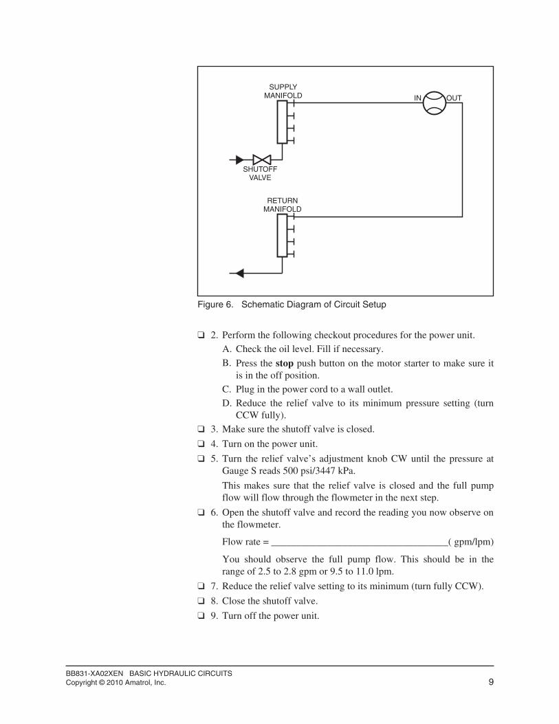
q 6. Open the shutoff valve and record the reading you now observe on the flowmeter.
Flow rate = ___________________________________( gpm/lpm)
You should observe the full pump flow. This should be in therange of 2.5 to 2.8 gpm or 9.5 to 11.0 lpm.
q 7. Reduce the relief valve setting to its minimum (turn fully CCW).
q 8. Close the shutoff valve.
q 9. Turn off the power unit.
BB831-XA02XEN BASIC HYDRAULIC CIRCUITSCopyright © 2010 Amatrol, Inc. 9
IN OUT
RETURNMANIFOLD
SUPPLYMANIFOLD
SHUTOFFVALVE
Figure 6. Schematic Diagram of Circuit Setup

q10. Now connect the flowmeter into the circuit shown in figure 7.
Be sure to use the small bore cylinder.
This location allows you to measure the return line flow of thecircuit.
q11. Turn on the power unit and adjust the pressure to 500 psi/3447 kPa.
q12. Open the shutoff valve.
q13. Now cycle the cylinder and observe the flowmeter reading.
Record the flow rate when the cylinder extends, retracts, and stops.
Did you notice that the flow rate is different when the cylinderextends and retracts? The rate you measured should have beenapproximately 2.5 gpm/9.5 lpm extending and 2.7 gpm/10.2 lpmretracting. You will learn in the next LAP why there is a difference between retracting and extending flow rates.
q14. Reduce the relief valve setting to its minimum.
q15. Close the shutoff valve and turn off the power unit.
q16. Move the DCV handle back and forth to remove all pressure.
q17. Disconnect the hoses and proceed to the activity.
BB831-XA02XEN BASIC HYDRAULIC CIRCUITSCopyright © 2010 Amatrol, Inc. 10
IN
OUT
IN
OUT
A
B
SMALL CYLINDER
Figure 7. Circuit Setup
OPERATION FLOW RATE(gpm/lpm)
Extending
Retracting
Stopped
Activity 1. Flowmeter Accuracy
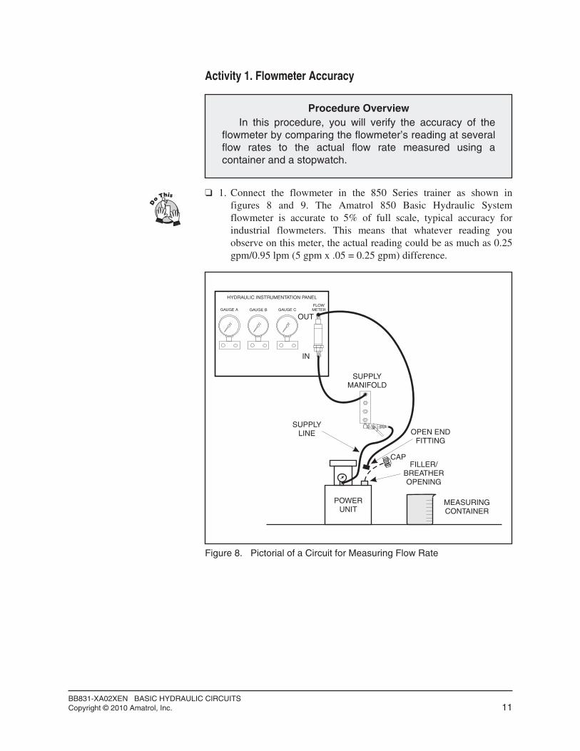
q 1. Connect the flowmeter in the 850 Series trainer as shown infigures 8 and 9. The Amatrol 850 Basic Hydraulic Systemflowmeter is accurate to 5% of full scale, typical accuracy forindustrial flowmeters. This means that whatever reading youobserve on this meter, the actual reading could be as much as 0.25gpm/0.95 lpm (5 gpm x .05 = 0.25 gpm) difference.
BB831-XA02XEN BASIC HYDRAULIC CIRCUITSCopyright © 2010 Amatrol, Inc. 11
Procedure OverviewIn this procedure, you will verify the accuracy of the
flowmeter by comparing the flowmeter’s reading at severalflow rates to the actual flow rate measured using acontainer and a stopwatch.
HYDRAULIC INSTRUMENTATION PANEL
GAUGE A GAUGE B GAUGE CFLOWMETER
SUPPLYMANIFOLD
OUT
IN
POWERUNIT
OPEN ENDFITTING
SUPPLYLINE
FILLER/BREATHEROPENING
CAP
MEASURINGCONTAINER
Figure 8. Pictorial of a Circuit for Measuring Flow Rate

q 2. Before restarting the power unit, unscrew the filler-breather cap on the reservoir and direct the open end of the hose into it.
q 3. Place a clean measuring container near the reservoir.
q 4. Record the volume of the measuring container below.
Volume of Container _____________________________gal./liters
q 5. Perform the following checkout procedures for the power unit.A. Check the oil level. Fill if necessary.B. Press the stop pushbutton on the motor starter to make sure it is
in the Off position.C. Plug in the power cord to the wall outlet.D. Reduce the relief valve to its minimum pressure setting. (Turn
CCW fully).q 6. Make sure the shutoff valve is closed. (Handle perpendicular to the
flow path).
The shutoff valve will be used to change the flow rates through the flowmeter.
q 7. Turn on the power unit.
q 8. Turn the relief valve adjustment knob CW until the pressure atGauge S reads 200 psi/1380 kPa.
q 9. Holding the open end of the hose directed into the filler-breatheropening, slowly open and adjust the shutoff valve until 0.5gpm/1.9 lpm is shown as flowing through the flowmeter.
Oil will be flowing out the open end fitting back into the tankthrough the filler-breather opening.
BB831-XA02XEN BASIC HYDRAULIC CIRCUITSCopyright © 2010 Amatrol, Inc. 12
IN OUT
RETURNMANIFOLD
SUPPLYMANIFOLD
SHUTOFFVALVE
FLOWMETER
OPEN-ENDFITTING
MEASURINGCONTAINER
Figure 9. Schematic Diagram of a Circuit for Measuring Flow Rate

q10. Quickly redirect the open end of the hose into the measuringcontainer and with a stopwatch, measure the time required to fill it. Direct the hose back to the filler-breather opening. Record the time to fill the container in the chart below:
q11. Close the shutoff valve, empty the container back into the powerunit tank through the filler-breather opening, and place thecontainer next to the reservoir.
q12. Again, while directing the open hose end into the filler-breatheropening, slowly open and adjust the shutoff valve to set the flow to 1.0 gpm/3.8 lpm through the flowmeter.
q13. Switch the hose back to the container and again measure the timerequired to fill it. Direct the hose back to the filler-breatheropening and record this time in the chart.
q14. Repeat steps 11, 12, and 13 for the other two flow rates listed inthe chart.
q15. Close the shutoff valve and reduce the power unit relief valvesetting to minimum (turn fully CCW).
q16. Turn off the power unit.
q17. Empty the container back into the power unit tank through thefiller-breather opening.
q18. Replace the filler-breather cap on the reservoir and clean up anyspilled oil, using clean shop rags.
BB831-XA02XEN BASIC HYDRAULIC CIRCUITSCopyright © 2010 Amatrol, Inc. 13
FLOWMETER TIME TO FILL
gpm lpm seconds
2.5 9.5
2.0 7.6
1.0 3.8
0.5 1.9

q19. Now calculate the actual flow rates for each flowmeter reading,using the following formula. Record your answers in the chartprovided.
Actual flow rate (gpm/lpm) = volume of container (gal / liters)
time to fill (minutes)
q20. Using your data from step 19, calculate the difference in flow ratebetween the flowmeter reading and the actual. Record in the chartin step 19.
None of your differences should exceed 0.25 gpm/0.95 lpm forthis flowmeter. Slight differences exceeding the stated accuracy of±5% of full flow could be attributed to measuring and timinginaccuracies.
BB831-XA02XEN BASIC HYDRAULIC CIRCUITSCopyright © 2010 Amatrol, Inc. 14
NOTESeconds must be converted to minutes for this formula.
FLOWMETER FLOW RATE ACTUAL FLOW RATE DIFFERENCE
gpm lpm gpm lpm gpm lpm
2.5 9.5
2.0 7.6
1.0 3.8
0.5 1.9
OBJECTIVE 3 DESCRIBE THE OPERATION OF A FIXED-DISPLACEMENTPUMP AND GIVE ITS SCHEMATIC SYMBOL
The pump generates fluid flow in a hydraulic system. Industrialhydraulic pumps use a positive displacement design. This means that ifthe shaft of the pump is turned at a constant speed by the electric motor,the pump produces a near-constant flow at its outlet regardless of thepressure.
There are two categories of positive displacement pumps: variabledisplacement and fixed-displacement. A variable displacement pump can change its flow rate, a fixed-displacement pump cannot. Its flow rate isfixed.
It is important to note that a fixed-displacement pump does notcreate pressure, only flow. Hydraulic system pressure develops onlywhen there is a resistance to flow. This resistance can be caused by aload on an actuator or fluid friction. Resistance will be covered in a laterLAP.
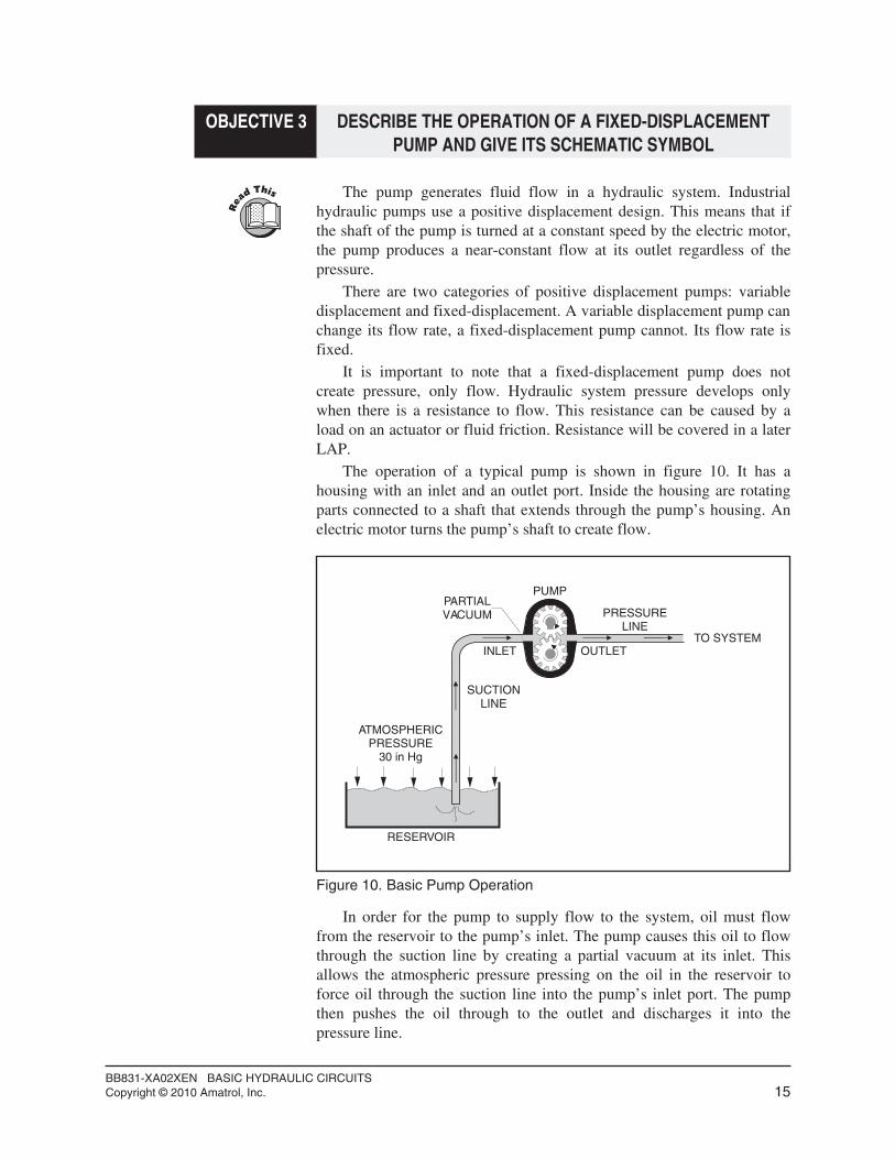
The operation of a typical pump is shown in figure 10. It has ahousing with an inlet and an outlet port. Inside the housing are rotatingparts connected to a shaft that extends through the pump’s housing. Anelectric motor turns the pump’s shaft to create flow.
In order for the pump to supply flow to the system, oil must flowfrom the reservoir to the pump’s inlet. The pump causes this oil to flowthrough the suction line by creating a partial vacuum at its inlet. Thisallows the atmospheric pressure pressing on the oil in the reservoir toforce oil through the suction line into the pump’s inlet port. The pumpthen pushes the oil through to the outlet and discharges it into thepressure line.
BB831-XA02XEN BASIC HYDRAULIC CIRCUITSCopyright © 2010 Amatrol, Inc. 15
ATMOSPHERICPRESSURE
30 in Hg
RESERVOIR
SUCTIONLINE
PUMP
PRESSURELINE
TO SYSTEMINLET OUTLET
PARTIALVACUUM
Figure 10. Basic Pump Operation

With all types of hydraulic pumps, the vacuum at the inlet is created byincreasing the volume inside the pump. The fluid then discharges to thesystem at the outlet port when the pump decreases the volume. Theoperation of a syringe, as shown in figure 11, demonstrates this principle.
It is important to remember that the pump does not develop pressureat its outlet. It only discharges the fluid at a certain flow rate. Pressuredevelops at the pump’s outlet only when there is a resistance to flow.
The schematic symbol for a fixed-displacement hydraulic pump isshown in figure 12 along with symbols for a coupling, electric motor,reservoir, and filter.
BB831-XA02XEN BASIC HYDRAULIC CIRCUITSCopyright © 2010 Amatrol, Inc. 16
DRAWING FLUID IN(INCREASING VOLUME)
PUSHING FLUID OUT(DECREASING VOLUME)
Figure 11. Pump Action of a Syringe
ELECTRICMOTOR
COUPLING
INLET
RESERVOIR
OUTLETSOLID ARROW INDICATES
MEDIUM IS LIQUID
CIRCLEINDICATES
ROTATING DRIVE
SUCTIONFILTER
PUMP
Figure 12. Schematic Symbols for Fixed-Displacement Hydraulic Pumpand Power Unit Components

Activity 2. Fixed-Displacement Pump Operation
q 1. Set up the circuit shown in figure 13.
This is the same circuit used in figure 6 except that the schematicsymbols for the power unit components have been added.
The oil flows from the pump through the supply line to the supplymanifold. It then goes through the flowmeter and back to thereservoir from the return manifold.
When the shutoff valve is closed, the oil pressure increases andcauses the relief valve to open. The oil from the pump then returnsto the reservoir through the relief valve.
In this circuit there is no resistance to flow when the shutoff valveis open, other than the resistance of the fittings and the flowmeter.
BB831-XA02XEN BASIC HYDRAULIC CIRCUITSCopyright © 2010 Amatrol, Inc. 17
Procedure OverviewIn this procedure, you will show that a
fixed-displacement pump produces the same flowregardless of pressure.
M
FLOWMETER
RETURNMANIFOLD
SUPPLYMANIFOLD
SHUTOFFVALVE
RELIEFVALVE
RETURNLINE
SUPPLYLINE
GAUGES
Figure 13. Circuit Setup

q 2. Perform the following checkout procedures for the power unit.A. Check the oil level. Fill if necessary.B. Press the stop push button on the motor starter to make sure it
is in the Off position.C. Plug in the power cord to a wall outlet.D. Reduce the relief valve to its minimum pressure setting (turn
CCW fully).q 3. Turn on the hydraulic power unit.
q 4. Make sure the shutoff valve is closed.
q 5. Adjust the relief valve pressure to 500 psi/3447 kPa.
q 6. Open the shutoff valve fully.
The pump should now be pumping its full flow through the flowmeter. The pressure reading at Gauge S should be less than 200psi/1380 kPa. This pressure is caused by the resistance of thequick-connect fittings and the flowmeter.
q 7. Turn the handle of the shutoff valve slightly until the pressure atGauge S reaches 200 psi/1380 kPa. Record the flow rate in thefollowing chart.
Partially closing the shutoff valve creates a resistance to flowwhich causes a back pressure at the pump’s outlet. You should still observe, however, that the flow does not change or, if it does, it isonly small.
q 8. Increase the pressure at Gauge S to 250 psi/1725 kPa by turningthe shutoff valve.
The flow reading you are now observing is again the full flow ofthe pump except the pump is pumping against a pressure of 250psi/1725 kPa.
Examine the flowmeter’s reading carefully to see if it has changedfrom the flow rate at 200 psi/1380 kPa. Then record this flow ratein the chart.
BB831-XA02XEN BASIC HYDRAULIC CIRCUITSCopyright © 2010 Amatrol, Inc. 18
PRESSURE(psi/kPa)
FLOW RATE(gpm/lpm)
200/1380 /
250/1725 /
300/2070 /
350/2415 /
400/2760 /

q 9. Repeat step 8 for each of the other pressures listed in the chart.
You should observe that the flow rate stays nearly the samebecause pump flow is constant regardless of pressure. However, as you increase the pressure, you may notice a slight drop in flowbecause the pump is less efficient at higher pressures. Some oilwill slip back to the inlet from the outlet.
q10. Reduce the relief valve’s setting to minimum.
q11. Close the shutoff valve completely.
q12. Turn off the power unit.
q13. Disconnect the hoses and store them.
OBJECTIVE 4 DESCRIBE THE OPERATION OF THREE TYPES OF FIXED-DISPLACEMENT PUMPS AND GIVE AN APPLICATION OF EACH
There are three common types of fixed-displacement pumps used inhydraulic systems: gear, vane, and piston. As shown in figure 14, themain difference among these three types is the design of the internalrotating parts.
All three of these pump types use positive displacement designs.
BB831-XA02XEN BASIC HYDRAULIC CIRCUITSCopyright © 2010 Amatrol, Inc. 19
Figure 14. Types of Hydraulic Pumps
VANE
PISTON
GEAR

Gear PumpGear pumps use two meshing gears. One of the gears directly
attaches to the pump’s shaft while the other gear acts as an idler gear. Atthe inlet side of the pump, the meshing gear teeth of the two gears rotateaway from each other. This creates an increasing volume which causes apartial vacuum or suction at the inlet. The atmospheric pressure at thereservoir then pushes the fluid into the inlet.
As fluid enters the inlet, it is trapped between the gear teeth and thehousing. The rotating gear teeth carry the fluid around to the outlet sidewhere it is pushed into the system.
This pump type is the least expensive and is used in low to mediumpressure applications, such as a trash compactor.
Vane PumpVane pumps have a rotor containing movable vanes that slide in and
out in radial slots of a rotor. As the shaft turns the rotor, the centrifugalforce throws the vanes out against a surrounding cam ring or housing.The suction at the inlet is created when the vanes rotate around towardthe inlet. Because the rotor is positioned off center, these vanes create anincreasing volume at the inlet which creates a partial vacuum.
BB831-XA02XEN BASIC HYDRAULIC CIRCUITSCopyright © 2010 Amatrol, Inc. 20
SHAFTCONNECTED TO DRIVE
(ELECTRIC MOTOR)
DRIVE GEAR
ROTARYMOTION
INLET
HOUSING IDLERGEAR
OUTLET
INCREASINGVOLUME
FLOW
Figure 15. Gear Pump Design

The pump moves fluid through it by trapping the fluid between thevanes and the pump housing. The fluid is pushed out of the pump at theoutlet by the decreasing volume created as the vanes slide back into therotor.
Applications where efficiency is somewhat important use vane pumps.
Piston PumpPiston pumps use a number of pistons which each create a pumping
action. As the pistons are rotated by the barrel, they move in and outbecause they are held on one end by an angled swashplate. This createsan increasing and decreasing volume action similar to a syringe.
High pressure applications such as presses and molding machinesoften use piston pumps. They are the most efficient but also the mostexpensive.
BB831-XA02XEN BASIC HYDRAULIC CIRCUITSCopyright © 2010 Amatrol, Inc. 21
SWASHPLATE
PISTONS BARREL
VALVE PLATE
SHAFT
Figure 17. A Piston Pump Design
PUMP SHAFT ROTOR
VANES
OUTLETINLET
HOUSING
INCREASEDVOLUME
SMALLVOLUME
Figure 16. Vane Pump Design

SEGMENT 1 SELF REVIEW
BB831-XA02XEN BASIC HYDRAULIC CIRCUITSCopyright © 2010 Amatrol, Inc. 22
1. Hydraulic flow rate can be measured by _________ or___________.
2. The two types of flowmeters used in hydraulics are____________ and _____________.
3. A(n) ________________ pump is the least expensive.
4. A(n) ________________ pump is the most efficient.
5. A fixed-displacement pump creates _______________ not____________.
6. A pump creates flow at its inlet by creating a(n)___________ volume.

SEGMENT 2
NEEDLE VALVES
OBJECTIVE 5 DESCRIBE THE MAIN FUNCTION OF A NEEDLE VALVE
The main function of a needle valve is to control the speed of anactuator by controlling the flow rate to that actuator. A typical needlevalve is shown in figure 18.
BB831-XA02XEN BASIC HYDRAULIC CIRCUITSCopyright © 2010 Amatrol, Inc. 23
Figure 18. Needle Valve Used in the 850 System

OBJECTIVE 6 DESCRIBE THE OPERATION OF A NEEDLE VALVEAND GIVE ITS SCHEMATIC SYMBOL
The needle valve controls flow rate by causing a restriction in theline. A typical valve consists of two major components: a valve bodyand an adjustment screw, as shown in figure 19.
The valve body consists of two ports with a passage connectingthem. This passage provides a flow path for the fluid. The adjustmentscrew can be turned in or out to vary the passage opening in the bodyfrom blocked to fully open. The adjustment screw has a tapered end forvery fine control of this orifice.
The needle valve controls the flow rate by adjusting the size of theopening or orifice. This will be explained in more detail in the activity.
The schematic symbol for a needle valve is shown in figure 20. Itshows two ports and an orifice. The angled arrow across the flow pathindicates that the orifice is variable.
BB831-XA02XEN BASIC HYDRAULIC CIRCUITSCopyright © 2010 Amatrol, Inc. 24
ADJUSTMENTSCREW
VALVE BODY
FLOW
PORT A
PORT B
Figure 19. Needle Valve Construction
SYMBOL EXPLANATION
VARIABLEORIFICE
PORTB
PORTA
ORIFICE
Figure 20. Needle Valve Schematic Symbol
Activity 3. Needle Valve Operation
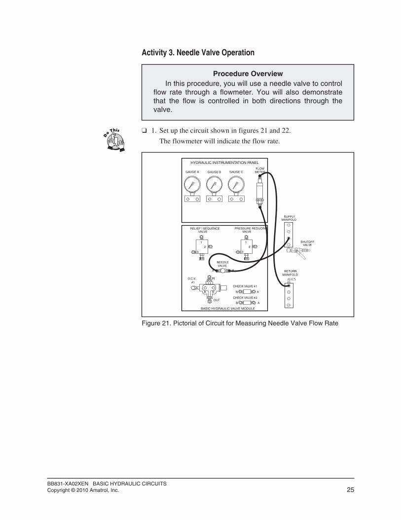
q 1. Set up the circuit shown in figures 21 and 22.
The flowmeter will indicate the flow rate.
BB831-XA02XEN BASIC HYDRAULIC CIRCUITSCopyright © 2010 Amatrol, Inc. 25
Procedure OverviewIn this procedure, you will use a needle valve to control
flow rate through a flowmeter. You will also demonstratethat the flow is controlled in both directions through thevalve.
HYDRAULIC INSTRUMENTATION PANEL
GAUGE A GAUGE B GAUGE CFLOWMETER
SUPPLYMANIFOLD
RETURNMANIFOLD
BASIC HYDRAULIC VALVE MODULE
1
2
3
1
2
3
A B
B A
B A
AA B
IN
OUT
RELIEF \ SEQUENCEVALVE
PRESSURE REDUCINGVALVE
VALVE
CHECK VALVE #1
CHECK VALVE #2
D.C.V.#1
NEEDLE
SHUTOFFVALVE
Figure 21. Pictorial of Circuit for Measuring Needle Valve Flow Rate

The long and short dashed lines drawn around the power unitcomponents tell you that these components are mounted together.
q 2. Perform the following checkout procedures for the power unit.A. Check the oil level. Fill if necessary.B. Press the stop push button on the motor starter to make sure it
is in the Off position.C. Plug in the power cord to a wall outlet.D. Reduce the relief valve to its minimum pressure setting (turn
CCW fully).q 3. Open the needle valve by turning the adjustment knob fully CCW.
q 4. Close the shutoff valve fully.
q 5. Turn on the hydraulic power unit.
q 6. Increase the pressure setting on the relief valve to 500 psi/3447kPa.
q 7. Open the shutoff valve and observe the flow rate through theflowmeter.
Gauge S Pressure ________________________________(psi/kPa)
Flow Rate ____________________________________(gpm/lpm)
You should observe that the flow rate indicates that the maximumflow of the pump is flowing through the needle valve.
The needle valve controls the flow rate by causing a restriction ofthe flow. When the adjustment screw is turned all the way out, thepassage is unblocked with a lower resistance to flow.
BB831-XA02XEN BASIC HYDRAULIC CIRCUITSCopyright © 2010 Amatrol, Inc. 26
NEEDLEVALVE
FLOWMETER
M
Figure 22. Schematic Diagram for Measuring Needle Valve Flow Rate
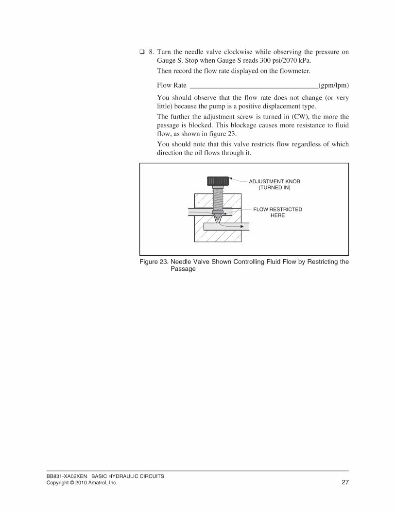
q 8. Turn the needle valve clockwise while observing the pressure onGauge S. Stop when Gauge S reads 300 psi/2070 kPa.
Then record the flow rate displayed on the flowmeter.
Flow Rate ____________________________________(gpm/lpm)
You should observe that the flow rate does not change (or verylittle) because the pump is a positive displacement type.
The further the adjustment screw is turned in (CW), the more thepassage is blocked. This blockage causes more resistance to fluidflow, as shown in figure 23.
You should note that this valve restricts flow regardless of whichdirection the oil flows through it.
BB831-XA02XEN BASIC HYDRAULIC CIRCUITSCopyright © 2010 Amatrol, Inc. 27
ADJUSTMENT KNOB(TURNED IN)
FLOW RESTRICTEDHERE
Figure 23. Needle Valve Shown Controlling Fluid Flow by Restricting thePassage

q 9. Continue turning the needle valve clockwise. Observe the flow rate as the pressure on Gauge S increases to 450 psi/3105 kPa.
You should observe that the upstream pressure continues to rise asthe needle valve’s opening gets smaller, as shown in figure 24.However, the flow rate should stay nearly constant because thepump is a positive displacement type and we have not yet reachedthe relief valve’s setting of 500 psi/3447 kPa.
BB831-XA02XEN BASIC HYDRAULIC CIRCUITSCopyright © 2010 Amatrol, Inc. 28
RESERVOIR
RELIEFVALVE
LOWPRESSURE
Figure 24. Relief Valve Closed, Flow Constant Through Needle Valve

q10. Now keep turning the needle valve’s adjustment knob clockwiseslowly and watch the flow rate reading as the pressure gets verynear to the relief valve setting (500 psi/3447 kPa).
You should observe that the flow rate starts to reduce noticeably.This occurs because the relief valve opens partially and allows part of the pump flow to bypass the flowmeter and go directly to thereservoir, as shown in figure 25.
q11. See if you can adjust the flow rate, using the needle valve, to eachof the following flow rates: 2.0 gpm/7.6 lpm, 1.5 gpm/5.7 lpm, 1.0 gpm/3.8 lpm and 0.5 gpm/1.9 lpm.
This will give you more experience with the adjustment of theneedle valve.
You should observe that the pressure continues to rise as theneedle valve’s opening gets smaller.
q12. Reduce the relief valve to its minimum pressure setting (turn CCW fully).
q13. Close the shutoff valve and turn off the power unit.
q14. Switch the hoses at the needle valve so that the supply hoseconnects to port B and the hose to the flowmeter connects to portA. This will allow oil to flow in the other direction through theneedle valve.
BB831-XA02XEN BASIC HYDRAULIC CIRCUITSCopyright © 2010 Amatrol, Inc. 29
RESERVOIR
RELIEFVALVE
HIGHPRESSURE
LOWPRESSURE
Figure 25. Relief Valve Partially Open, Flow Reduced Through NeedleValve

q15. Turn on the hydraulic power unit and increase the pressure settingon the relief valve to 500 psi/3447 kPa.
q16. Open the shutoff valve.
q17. Adjust the needle valve to provide 2.0 gpm/7.6 lpm, 1.5 gpm/5.7lpm, 1.0 gpm/3.8 lpm and 0.5 gpm/1.9 lpm just as you did in step11.
This will verify the ability of the needle valve to control flowwhen the flow is reversed through it.
q18. Reduce the relief valve to its minimum pressure setting (turn CCW fully).
q19. Close the shutoff valve and turn off the power unit.
SKILL 2 CONNECT AND OPERATE A NEEDLE VALVE TO CONTROLTHE SPEED OF AN ACTUATOR
q 1. Set up the circuit, as shown in figures 26 and 27.
In this circuit, the needle valve restricts the flow to the DCV andon to the cylinder.
BB831-XA02XEN BASIC HYDRAULIC CIRCUITSCopyright © 2010 Amatrol, Inc. 30
Procedure OverviewIn this procedure, you will use a needle valve to control
the speed of a cylinder. This is a common task done everyday in industry.
HYDRAULIC INSTRUMENTATION PANEL
GAUGE A GAUGE B GAUGE CFLOWMETER
SUPPLYMANIFOLD
RETURNMANIFOLD
BASIC HYDRAULIC VALVE MODULE
1
2
3
1
2
3
A B
B A
B A
A B
IN
OUT
RELIEF \ SEQUENCEVALVE
PRESSURE REDUCINGVALVE
VALVE
CHECK VALVE #1
CHECK VALVE #2
D.C.V.#1
NEEDLE
HYDRAULIC ACTUATOR MODULE
CYLINDER
A
B
A
B
CYLINDER
FLOWCONTROL
#1
FLOWCONTROL
#2
MOTOR
SHUTOFFVALVE
Figure 26. Circuit for Controlling the Speed of a Cylinder with the NeedleValve

q 2. Perform the following checkout procedures for the power unit.A. Check the oil level. Fill if necessary.B. Press the stop push button on the motor starter to make sure it
is in the Off position.C. Plug in the power cord to a wall outlet.D. Reduce the relief valve to its minimum pressure setting (turn
CCW fully).q 3. Turn on the power unit.
q 4. Increase the pressure setting on the relief valve to 500 psi/3447kPa.
q 5. Open the shutoff valve.
q 6. Open the needle valve fully (CCW).
q 7. Cycle the cylinder back and forth by shifting the lever of the DCV. Notice the speed of the cylinder.
It should be relatively fast (less than a second) because full pumpflow is going to the cylinder.
BB831-XA02XEN BASIC HYDRAULIC CIRCUITSCopyright © 2010 Amatrol, Inc. 31
SMALL BORECYLINDER
IN
OUT
A
B
Figure 27. Schematic of Circuit for Controlling the Speed of a Cylinderwith a Needle Valve

q 8. As you continue to cycle the DCV, turn the needle valve’sadjustment knob CW until it takes approximately four seconds forthe cylinder to extend. You may have to turn it several turns before you start to see any speed change at all.
The flow rate of oil into the actuator determines the speed of ahydraulic actuator. To show how this works, consider the cylindershown in figure 28. In order to extend the cylinder, the oil must fill the volume created when the cylinder extends. The rate at whichthe oil flows determines how fast this volume can fill. Forexample, if our cylinder in figure 28 creates a total volume of 2liters when extended and the flow rate is 1 lpm, the time to extendis 2 minutes (2 ÷ 1 = 2). If the flow rate is higher, it will take lesstime to fill the volume and the faster the actuator speed will be.
q 9. Test your ability to provide other cylinder speeds by adjusting theneedle valve to other openings.
q10. Open the needle valve by turning the adjustment knob fully CCW.
Leave the system running and continue to the next skill.
BB831-XA02XEN BASIC HYDRAULIC CIRCUITSCopyright © 2010 Amatrol, Inc. 32
CYLINDERRETRACTED
CYLINDEREXTENDED
2 LITERS OF OIL
Figure 28. Volume of Oil to Extend
SKILL 3 CONTROL THE SPEED OF AN ACTUATOR USINGA MANUALLY-OPERATED DCV
q 1. Continuing from the previous skill, gently push the lever of theDCV slightly off center so that the spool of the DCV is onlypartially shifted. Observe the speed of the cylinder.
You should observe that the cylinder extends at a slower speed.
This technique is called feathering a directional control valve. It iscommonly used on mobile equipment, such as tractors andbackhoes, to control the speed of an actuator. In these applications, the needle valve is not needed. The spool inside the DCV has longtapers that provide a gradually increasing path for the oil to flow.This technique works because the valves are manually shiftedallowing you to move the spool to any position you desire.
q 2. After the cylinder is extended, pull the lever out so that the spool is shifted only slightly in the other direction. Observe the cylinder’sspeed as it retracts.
q 3. Repeat steps 1 and 2 several times and try different lever positionsto observe your ability to change the speed of the cylinder bycontrolling the amount of DCV shift.
q 4. Retract the cylinder rod fully.
q 5. Reduce the relief valve’s pressure setting to the minimum setting(turn CCW).
q 6. Close the shutoff valve.
q 7. Turn off the power unit.
q 8. Move the handle of the DCV back and forth to remove anypressure in the circuit.
q 9. Disconnect the circuit and store the components.
BB831-XA02XEN BASIC HYDRAULIC CIRCUITSCopyright © 2010 Amatrol, Inc. 33
Procedure OverviewIn this procedure, you will use the directional control
valve to control the speed of the cylinder by opening itpartially. This action causes the DCV spool to restrict theflow similar to the needle valve. Hydraulic systems inconstruction equipment such as backhoes often use thistechnique.
NOTEControl of cylinder speed may be sensitive because this DCV
was not made with tapers on the spool.
SEGMENT 2 SELF REVIEW
BB831-XA02XEN BASIC HYDRAULIC CIRCUITSCopyright © 2010 Amatrol, Inc. 34
1. The __________ of an actuator is determined by the flowrate of oil into the actuator.
2. To close a needle valve, turn the adjustment knob ________.
3. Controlling the amount of DCV shift to control the speed ofan actuator is called _____________.
4. The needle valve controls the flow rate by causing a(n)__________.
5. The needle valve body has __________ ports.
6. Flow is restricted through a(n) ____________________regardless of which direction the oil flows through it.
SEGMENT 3
BASIC MOTOR CIRCUITS
OBJECTIVE 7 DESCRIBE THE FUNCTION OF A HYDRAULIC MOTORAND GIVE AN APPLICATION
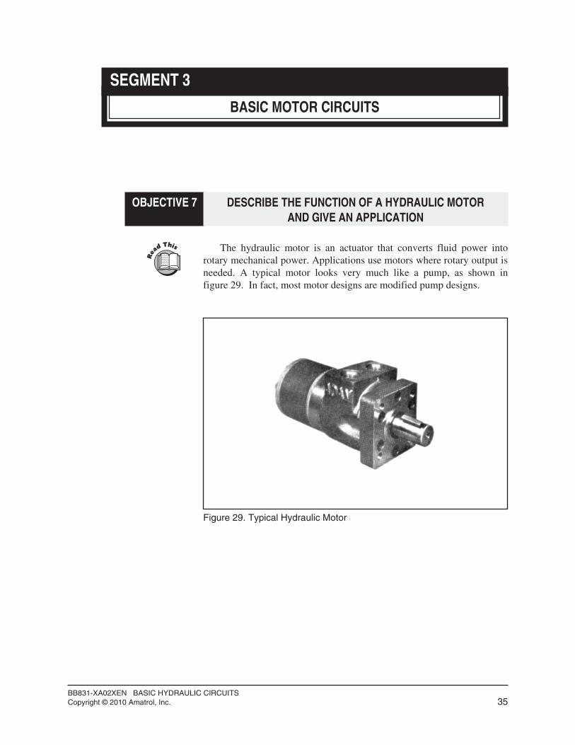
The hydraulic motor is an actuator that converts fluid power intorotary mechanical power. Applications use motors where rotary output is needed. A typical motor looks very much like a pump, as shown infigure 29. In fact, most motor designs are modified pump designs.
BB831-XA02XEN BASIC HYDRAULIC CIRCUITSCopyright © 2010 Amatrol, Inc. 35
Figure 29. Typical Hydraulic Motor
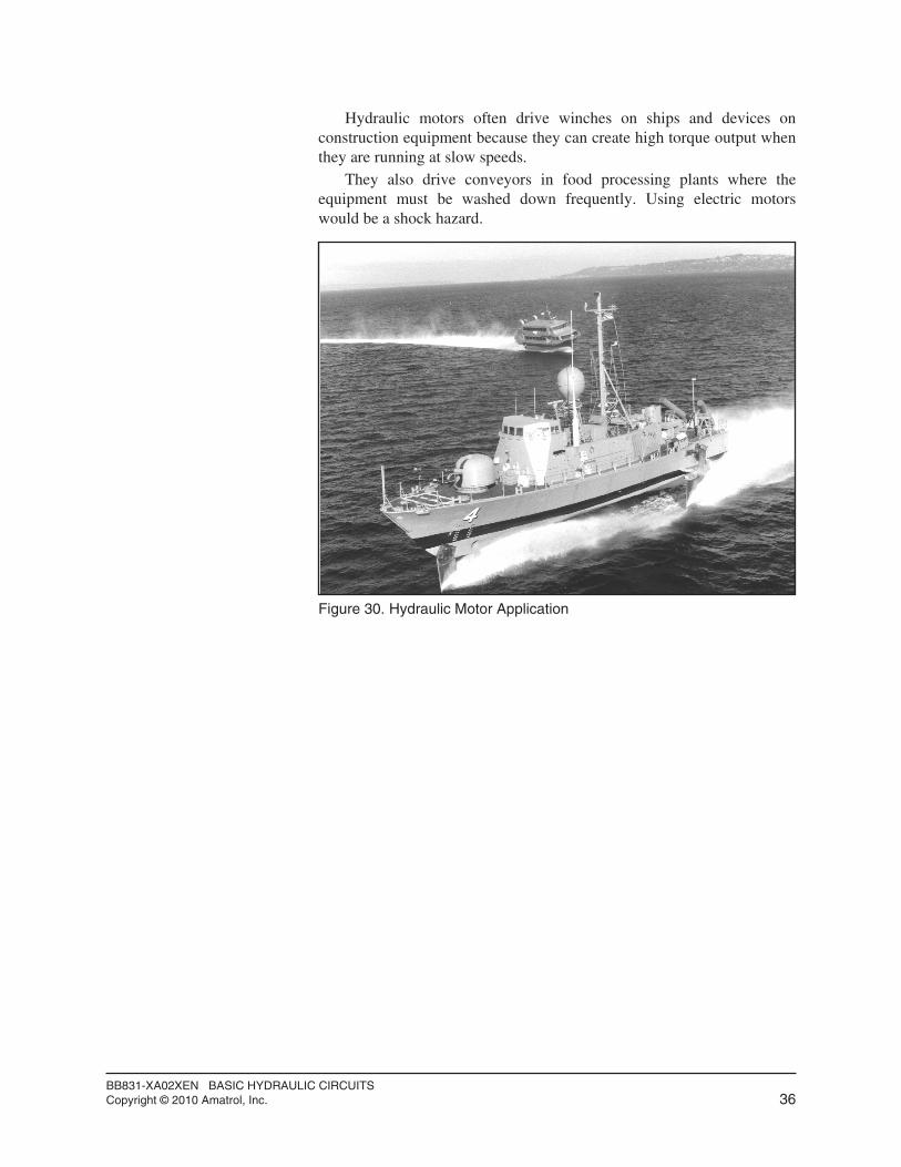
Hydraulic motors often drive winches on ships and devices onconstruction equipment because they can create high torque output whenthey are running at slow speeds.
They also drive conveyors in food processing plants where theequipment must be washed down frequently. Using electric motorswould be a shock hazard.
BB831-XA02XEN BASIC HYDRAULIC CIRCUITSCopyright © 2010 Amatrol, Inc. 36
Figure 30. Hydraulic Motor Application
OBJECTIVE 8 DESCRIBE THE OPERATION OF A HYDRAULIC MOTORAND GIVE ITS SCHEMATIC SYMBOL
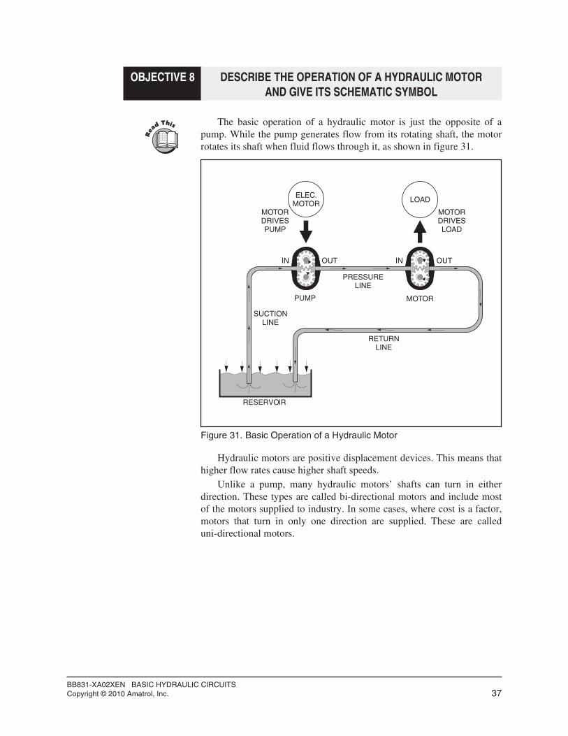
The basic operation of a hydraulic motor is just the opposite of apump. While the pump generates flow from its rotating shaft, the motorrotates its shaft when fluid flows through it, as shown in figure 31.
Hydraulic motors are positive displacement devices. This means thathigher flow rates cause higher shaft speeds.
Unlike a pump, many hydraulic motors’ shafts can turn in eitherdirection. These types are called bi-directional motors and include mostof the motors supplied to industry. In some cases, where cost is a factor,motors that turn in only one direction are supplied. These are calleduni-directional motors.
BB831-XA02XEN BASIC HYDRAULIC CIRCUITSCopyright © 2010 Amatrol, Inc. 37
RESERVOIR
SUCTIONLINE
PUMP MOTOR
PRESSURELINE
ELEC.MOTOR LOAD
MOTORDRIVESPUMP
MOTORDRIVESLOAD
IN INOUT OUT
RETURNLINE
Figure 31. Basic Operation of a Hydraulic Motor
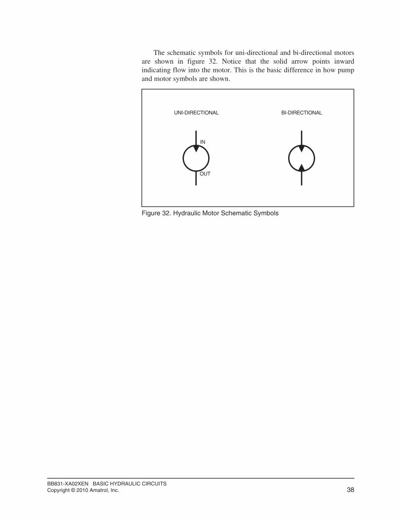
The schematic symbols for uni-directional and bi-directional motorsare shown in figure 32. Notice that the solid arrow points inwardindicating flow into the motor. This is the basic difference in how pumpand motor symbols are shown.
BB831-XA02XEN BASIC HYDRAULIC CIRCUITSCopyright © 2010 Amatrol, Inc. 38
IN
OUT
UNI-DIRECTIONAL BI-DIRECTIONAL
Figure 32. Hydraulic Motor Schematic Symbols

SKILL 4 CONNECT AND OPERATE A BI-DIRECTIONAL HYDRAULICMOTOR USING A 3-POSITION, MANUALLY-OPERATED DCV
q 1. Set up the hydraulic motor circuit shown in figures 33 and 34.
BB831-XA02XEN BASIC HYDRAULIC CIRCUITSCopyright © 2010 Amatrol, Inc. 39
Procedure OverviewIn this procedure, you will set up a basic hydraulic
circuit that will allow you to stop, start, and operate a motor in both directions of rotation. This circuit uses a 4-way,3-position DCV to control a bi-directional motor.
HYDRAULIC INSTRUMENTATION PANEL
GAUGE A GAUGE B GAUGE CFLOWMETER
SUPPLYMANIFOLD
RETURNMANIFOLD
BASIC HYDRAULIC VALVE MODULE
1
2
3
1
2
3
A B
B A
B A
A B
IN
OUT
RELIEF \ SEQUENCEVALVE
PRESSURE REDUCINGVALVE
VALVE
CHECK VALVE #1
CHECK VALVE #2
D.C.V.#1
NEEDLE
HYDRAULIC ACTUATOR MODULE
CYLINDER
A
B
A
B
CYLINDER
FLOWCONTROL
#1
FLOWCONTROL
#2
MOTOR
SHUTOFFVALVE
Figure 33. Pictorial of a Basic Hydraulic Motor Circuit
BB831-XA02XEN BASIC HYDRAULIC CIRCUITSCopyright © 2010 Amatrol, Inc. 40
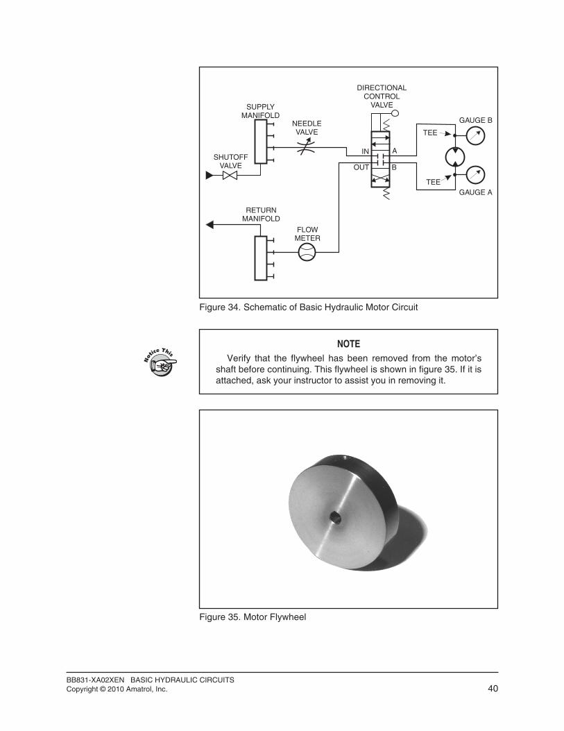
NOTEVerify that the flywheel has been removed from the motor’s
shaft before continuing. This flywheel is shown in figure 35. If it is attached, ask your instructor to assist you in removing it.
Figure 35. Motor Flywheel
SUPPLYMANIFOLD
RETURNMANIFOLD
DIRECTIONALCONTROL
VALVE
FLOWMETER
SHUTOFFVALVE
GAUGE B
GAUGE A
IN
OUT
A
B
TEE
TEE
NEEDLEVALVE
Figure 34. Schematic of Basic Hydraulic Motor Circuit

q 2. Perform the following checkout procedures before starting thehydraulic power unit.A. Check the oil level. Fill if necessary.B. Press the stop push button on the motor starter to make sure the
starter is in the Off position.C. Plug in the power cord to a wall outlet.D. Reduce the relief valve to its minimum pressure setting (turn
CCW fully).q 3. Close the needle valve completely and then open it 1/4 turn. This
should cause the motor to rotate at slow speed when the DCV isoperated and allow you to observe its operation.
q 4. Turn on the power unit.
q 5. Increase the relief valve’s pressure setting to 300 psi/2070 kPa.
q 6. Open the shutoff valve.
q 7. Test the ability of the circuit to drive the motor in two directionsby operating the lever of the DCV. Record below which leverposition causes the motor’s shaft to turn in the CW direction andthen in the CCW direction when looking at the motor shaft fromthe back of the motor.
Like the double-acting cylinder, the motor’s direction of rotationchanges by reversing the hose connections.
q 8. Reduce the relief valve to minimum and turn off the power unit.
q 9. Reverse the hoses to the hydraulic motor.
q10. Turn on the power unit and increase the pressure to 300 psi/2070kPa.
q11. Now test the motor’s operation by pushing the lever in and pullingit out. Record below which lever position creates CW and CCWrotation.
You should observe that the motor runs in the opposite directionfor each position of the handle.
BB831-XA02XEN BASIC HYDRAULIC CIRCUITSCopyright © 2010 Amatrol, Inc. 41
MOTOR DIRECTION LEVER POSITION (IN/OUT)
CW
CCW
MOTOR DIRECTION LEVER POSITION (IN/OUT)
CW
CCW

q12. Perform the following substeps to adjust the speed of the motorusing the needle valve.
This will allow you to test the ability to measure motor speed.A. Push the lever of the DCV in and hold it so that the motor runs.B. Adjust the setting of the needle valve so that the flow rate is 0.5
gpm/1.9 lpm. The motor should be operating at a low speed.Also, listen carefully to the pitch of the motor.
C. Test the effect that flow rate has on motor speed by opening the needle valve CCW until the flow rate at the flowmeter reads0.75 gpm/2.9 lpm. Listen for any change in speed in the motor.A higher pitch indicates faster speed; a lower pitch indicatesslower speed.Record your observations in the chart.
D. Repeat substep C adjusting the needle valve for each of theother flow rates in the chart.You should have observed that motor speed increases as flowrate through the motor increases and the motor speed slows asflow rate through the motor decreases.
E. Release the handle of the DCV.
BB831-XA02XEN BASIC HYDRAULIC CIRCUITSCopyright © 2010 Amatrol, Inc. 42
MOTOR FLOW(gpm/lpm)
MOTOR SPEED(Same/Increasing/Decreasing)
0.75 / 2.8
1.0 / 3.8
1.5 / 5.7
2.0 / 7.6
1.0 / 3.8
q13. Now adjust the circuit using the following substeps so you canobserve the effects of rapidly reversing motor rotation.A. Push the lever of the DCV in and hold it so the motor runs.B. Adjust the needle valve so that the flow rate is 0.75 gpm/2.9
lpm.q14. Now test the ability of the motor to be quickly reversed by shifting
the lever of the directional control valve quickly from a full-inposition to a full-out position. Record the peak pressure reading on Gauge A when you do this.
No flywheel, moderate speed:
Peak Pressure, Gauge A ___________________________(psi/kPa)
q15. Stop the motor and open the needle valve completely.
This valve setting will allow you to test the reversibility of themotor at a high speed.
q16. Repeat step 14 again to see how smoothly and quickly the motorshifts direction at high speed. Record the new peak pressure.
No flywheel, high speed:
Peak Pressure, Gauge A ___________________________(psi/kPa)
You should observe that the motor reverses very smoothly andquickly. The peak pressure will be greater than that of step 14.
q17. Release the lever of the DCV to stop the motor.
q18. Reduce the relief valve pressure to minimum and turn off thepower unit.
BB831-XA02XEN BASIC HYDRAULIC CIRCUITSCopyright © 2010 Amatrol, Inc. 43
NOTEOne of the features of a hydraulic system is that it can reverse
the actuator’s direction very suddenly without causing anydamage. In contrast, electric motors can burn up if they arereversed suddenly and repeatedly. In the remaining steps of thisskill, you will demonstrate the ability of the motor to reversedirection quickly.

q19. Perform the following substeps to put the flywheel on the shaft ofthe motor, as shown in figure 38.
A. Locate the flywheel and remove the first set screw using a3/32-inch Allen wrench, as shown in figure 36.There are two set screws in the flywheel. One tightens againstthe shaft. The other (the one you are removing) holds thesecond set screw in place.
B. Use a 3/32-inch Allen wrench to back the second set screwaway from the key slot of the flywheel.This will allow the flywheel to slide onto the shaft easily. Youonly need to turn the Allen wrench CCW a few turns to do this.
C. Verify that the key shown in figure 37 is in the key slot of themotor shaft.
D. Orient the flywheel in your hand so that the set screw accesshole is closer to the motor as shown in figures 37 and 38.
E. Orient the flywheel in your hand so that the key slot is alignedwith the key on the motor shaft and slide the flywheel onto theshaft.
F. Then position the flywheel on the shaft as shown in figure 38.G. Tighten the second set screw.
BB831-XA02XEN BASIC HYDRAULIC CIRCUITSCopyright © 2010 Amatrol, Inc. 44
Figure 36. Removing a Set Screw from the Flywheel Using a 3/32-inchAllen Wrench
NOTEFor safety and proper operation, the flywheel must be locked
firmly to the motor shaft. As shown in figures 37 and 38, theflywheel is locked using slots in the flywheel, a slot in the shaft,two set screws, and a key.

H. Add and tighten the first set screw on top of the second setscrew to jam the set screws so the flywheel won’t come loose(a safety precaution). This will make sure the flywheel issecurely mounted to the shaft.The flywheel will show the effect of a load when a motorreverses direction in the following steps.
BB831-XA02XEN BASIC HYDRAULIC CIRCUITSCopyright © 2010 Amatrol, Inc. 45
KEY
KEY SLOTS
FLY WHEEL
SET SCREWACCESS HOLE
HYDRAULICMOTOR
Figure 37. Flywheel and Motor Showing Key Slots
HYDRAULICMOTOR
SET SCREWACCESS HOLE
KEY
MOTORSHAFT
FLYWHEEL
SECONDSET
SCREW
FIRSTSET
SCREW
Figure 38. Proper Position of Flywheel on Motor Shaft

q20. Turn on the power unit and set the relief valve pressure to 300psi/2070 kPa.
q21. Close the needle valve completely. Then open it 1/4 turn.
q22. Push the lever of the DCV in and hold it so that the motor runs.
q23. Adjust the setting of the needle valve so that the flowmeter reads0.75 gpm/2.9 lpm.
q24. Use the DCV to quickly reverse the motor direction. Observe tosee how the motor shifts direction with a load. Observe the peakpressure.
Flywheel load, moderate speed.
Peak Pressure, Gauge A __________________________(psi/kPa)
You should observe that the motor smoothly and quickly reversesdirection, even though the peak pressure is higher.
q25. Release the lever of the DCV.
q26. Open the needle valve fully.
q27. Repeat step 24 and observe.
Flywheel load, high speed.
Peak Pressure, Gauge A ___________________________(psi/kPa)
You should observe that the motor smoothly reverses directioneven though it takes more time and the peak pressure is evenhigher.
q28. Release the lever of the DCV to stop the motor.
q29. Reduce the relief valve setting to minimum.
q30. Turn off the power unit.
q31. Close the shutoff valve.
q32. Shift the lever of the DCV back and forth to remove any pressurelocked in the circuit.
q33. Remove the flywheel.
q34. Disconnect the circuit and store the components.
BB831-XA02XEN BASIC HYDRAULIC CIRCUITSCopyright © 2010 Amatrol, Inc. 46

OBJECTIVE 9 LIST THREE TYPES OF HYDRAULIC MOTORSAND GIVE AN APPLICATION OF EACH
As with pumps, there are three basic designs of motors:
• Gear Motors
• Vane Motors
• Piston Motors
Gear MotorsThere are two types of gear motors available: standard gear motors
and gerotor motors. A standard gear motor uses two meshing spur gearsthat rotate inside a housing. This design is so similar to its pumpcounterpart that many gear motors can be used as pumps.
The gerotor motor, shown in figure 39, uses an internal gear thatrotates inside a ring gear similar to planetary gears. Gerotor motors aregenerally less efficient than other types of motors but they are veryinexpensive and highly durable under extreme environmental conditions. Gerotor motors are very popular for light-duty mobile applicationsincluding agriculture, mining, and construction.
BB831-XA02XEN BASIC HYDRAULIC CIRCUITSCopyright © 2010 Amatrol, Inc. 47
Figure 39. The Gerotor Motor
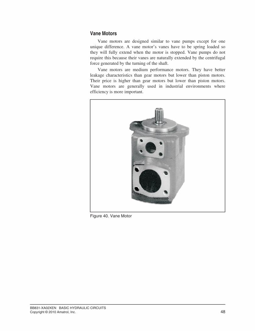
Vane MotorsVane motors are designed similar to vane pumps except for one
unique difference. A vane motor’s vanes have to be spring loaded sothey will fully extend when the motor is stopped. Vane pumps do notrequire this because their vanes are naturally extended by the centrifugalforce generated by the turning of the shaft.
Vane motors are medium performance motors. They have betterleakage characteristics than gear motors but lower than piston motors.Their price is higher than gear motors but lower than piston motors.Vane motors are generally used in industrial environments whereefficiency is more important.
BB831-XA02XEN BASIC HYDRAULIC CIRCUITSCopyright © 2010 Amatrol, Inc. 48
Figure 40. Vane Motor

Piston MotorsThere are three types of piston motors available: in-line, bent axis,
and radial. An example of each type is shown in figure 41. The inline isby far the most common.
Applications use piston motors where high performance is needed.They give exact speed regulation, low speed-high torque, and highspeed-low torque. They have low internal friction and very closetolerances yielding a very high efficiency.
BB831-XA02XEN BASIC HYDRAULIC CIRCUITSCopyright © 2010 Amatrol, Inc. 49
Figure 41. Types of Piston Motors
BENT AXIS
RADIALINLINE
SEGMENT 3 SELF REVIEW
BB831-XA02XEN BASIC HYDRAULIC CIRCUITSCopyright © 2010 Amatrol, Inc. 50
1. The actuator that produces rotary motion is called a(n)_____ .
2. To increase the speed of a hydraulic motor, increase the_________.
3. The three types of hydraulic motors are ____, ____, and______.
4. The direction of rotation of a motor is determined byviewing the shaft from the ______ of the motor.
5. A(n) _________ is used to rapidly change direction ofrotation of a motor.
6. _________________ motors are inexpensive and highlydurable under extreme environmental conditions.
SEGMENT 4
HYDRAULIC SCHEMATICS
OBJECTIVE 10 DESCRIBE EIGHT BASIC RULES FOR DRAWINGHYDRAULIC SCHEMATICS
Up to this point, a number of hydraulic schematic symbols and some basic schematics have been covered. However, how to draw thesecircuits has not been discussed.
Eight new rules to when drawing hydraulic schematics are:
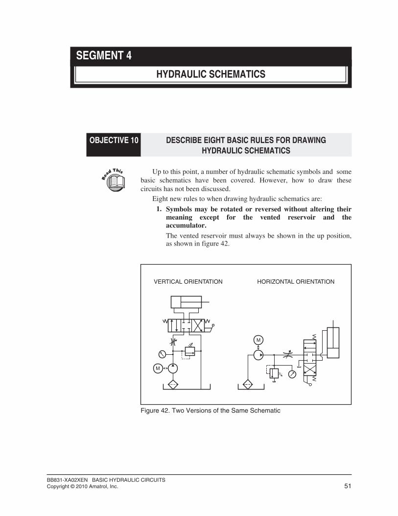
1. Symbols may be rotated or reversed without altering theirmeaning except for the vented reservoir and theaccumulator.
The vented reservoir must always be shown in the up position,as shown in figure 42.
BB831-XA02XEN BASIC HYDRAULIC CIRCUITSCopyright © 2010 Amatrol, Inc. 51
M
M
VERTICAL ORIENTATION HORIZONTAL ORIENTATION
Figure 42. Two Versions of the Same Schematic

2. The vented reservoir symbol may be shown as many timesas desired without indicating that there is more than onereservoir.
By showing that a line returns to the tank without plumbing itback to the one reservoir allows the drawing to be read moreeasily.
BB831-XA02XEN BASIC HYDRAULIC CIRCUITSCopyright © 2010 Amatrol, Inc. 52
M
INDICATES THATRETURN LINE GOESTO THE RESERVOIR
Figure 43. Reservoir Represented with More than One Symbol

3. Lines (conductors) are shown either horizontally orvertically on the schematic diagram. Diagonal lines shouldnot be drawn.
4. Connecting lines, crossing lines, and blocked lines should bedrawn as shown in figure 44.
BB831-XA02XEN BASIC HYDRAULIC CIRCUITSCopyright © 2010 Amatrol, Inc. 53
CONNECTED LINES BLOCKED LINE
CROSSING LINES BLOCKED LINE
Figure 44. Line Connections

5. Symbols show connections, flow paths, and functions only.
They do not show construction, size, location of ports, flow rate, or pressures.
6. Each symbol is drawn to show normal, at rest, de-energized, or neutral condition of the component.
The only exception is when multiple diagrams are drawnshowing various phases of circuit operation.
7. Letters may be used as part of graphic symbols but are notnecessary except M inside a circle to denote electric drivemotor and ∑ inside the flow meter symbol to show that it isa totalizing flow meter.
8. A solid arrow or triangle, as shown in figure 45, can indicate the flow direction of oil from the pump and the circuit. Thisarrow can be used by itself to represent the power unit.
BB831-XA02XEN BASIC HYDRAULIC CIRCUITSCopyright © 2010 Amatrol, Inc. 54
M
SUPPLY FROMPUMP
RETURN TORESERVOIR
Figure 45. Flow To and From the Pump

SKILL 5 DRAW A HYDRAULIC SCHEMATIC FROM THE ACTUALCIRCUIT CONNECTIONS ON A PICTORIAL
q 1. On a copy of figure 47, draw the circuit schematic for the pictorialshown in figure 46. Start from the supply and return manifoldconnections as shown. You may show flexible hoses as rigidconnectors (i.e. a straight line) and omit all quick-connect symbols.
BB831-XA02XEN BASIC HYDRAULIC CIRCUITSCopyright © 2010 Amatrol, Inc. 55
Procedure OverviewIn this procedure, you will draw schematics by looking
at actual circuit connections on pictorials. This is acommon requirement in industry because the schematics are not often readily available.
HYDRAULIC INSTRUMENTATION PANEL
GAUGE A GAUGE B GAUGE CFLOWMETER
SUPPLYMANIFOLD
RETURNMANIFOLD
HYDRAULIC ACTUATOR MODULE
CYLINDER
A
B
A
B
CYLINDER
FLOWCONTROL
#1
FLOWCONTROL
#2
MOTOR
BASIC HYDRAULIC VALVE MODULE
1
2
3
1
2
3
A B
B A
B A
AA B
IN
OUT
RELIEF \ SEQUENCEVALVE
PRESSURE REDUCINGVALVE
VALVE
CHECK VALVE #1
CHECK VALVE #2
D.C.V.#1
NEEDLE
Figure 46. Pictorial of a Basic Hydraulic Cylinder Circuit

q 2. On a copy of figure 49, draw the circuit schematic for the pictorialshown in figure 48. Start from the supply and return manifoldconnections as shown. You may show flexible hoses as rigidconnectors (i.e. a straight line) and omit all quick-connect symbols.
BB831-XA02XEN BASIC HYDRAULIC CIRCUITSCopyright © 2010 Amatrol, Inc. 56
Figure 47. Schematic of a Basic Hydraulic Cylinder Circuit
HYDRAULIC INSTRUMENTATION PANEL
GAUGE A GAUGE B GAUGE CFLOWMETER
SUPPLYMANIFOLD
RETURNMANIFOLD
BASIC HYDRAULIC VALVE MODULE
1
2
3
1
2
3
A B
B A
B A
A B
IN
OUT
RELIEF \ SEQUENCEVALVE
PRESSURE REDUCINGVALVE
VALVE
CHECK VALVE #1
CHECK VALVE #2
D.C.V.#1
NEEDLE
HYDRAULIC ACTUATOR MODULE
CYLINDER
A
B
A
B
CYLINDER
FLOWCONTROL
#1
FLOWCONTROL
#2
MOTOR
SHUTOFFVALVE
Figure 48. Pictorial of a Basic Hydraulic Motor circuit

q 3. Draw the circuit schematic for the pictorial shown in figure 50 on a copy of figure 51. Start from the supply and return manifoldconnections as shown. You may show flexible hoses as rigidconnectors (i.e. a straight line) and omit all quick-connect symbols.
BB831-XA02XEN BASIC HYDRAULIC CIRCUITSCopyright © 2010 Amatrol, Inc. 57
Figure 49. Schematic of a Basic Hydraulic Motor Circuit
HYDRAULIC INSTRUMENTATION PANEL
GAUGE A GAUGE B GAUGE CFLOWMETER
SUPPLYMANIFOLD
RETURNMANIFOLD
BASIC HYDRAULIC VALVE MODULE
1
2
3
1
2
3
A B
B A
B A
A B
IN
OUT
RELIEF \ SEQUENCEVALVE
PRESSURE REDUCINGVALVE
VALVE
CHECK VALVE #1
CHECK VALVE #2
D.C.V.#1
NEEDLE
HYDRAULIC ACTUATOR MODULE
CYLINDER
A
B
A
B
CYLINDER
FLOWCONTROL
#1
FLOWCONTROL
#2
MOTOR
SHUTOFFVALVE
Figure 50. Pictorial of a Hydraulic Circuit

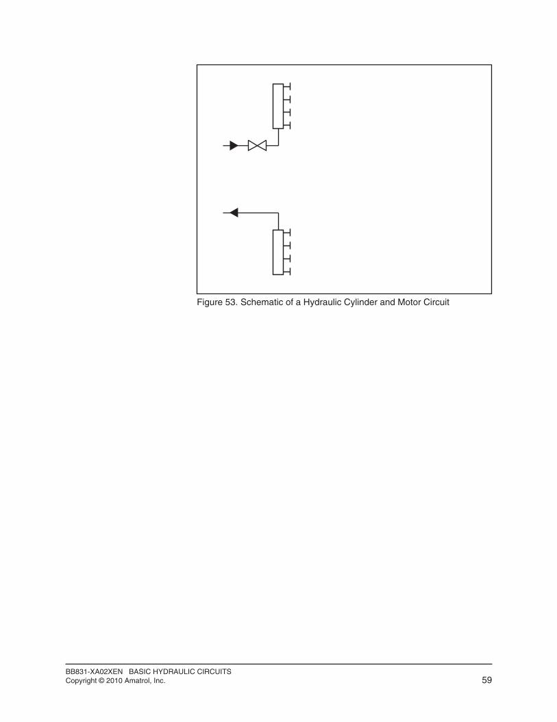
q 4. Draw the circuit schematic for the pictorial shown in figure 52 on a copy of figure 53. Start from the supply and return manifoldconnections as shown. You may show flexible hoses as a rigidconnector (i.e. a straight line) and omit all quick-connect symbols.
BB831-XA02XEN BASIC HYDRAULIC CIRCUITSCopyright © 2010 Amatrol, Inc. 58
HYDRAULIC INSTRUMENTATION PANEL
GAUGE A GAUGE B GAUGE CFLOWMETER
SUPPLYMANIFOLD
RETURNMANIFOLD
BASIC HYDRAULIC VALVE MODULE
1
2
3
1
2
3
A B
B A
B A
A B
IN
OUT
RELIEF \ SEQUENCEVALVE
PRESSURE REDUCINGVALVE
VALVE
CHECK VALVE #1
CHECK VALVE #2
D.C.V.#1
NEEDLE
HYDRAULIC ACTUATOR MODULE
CYLINDER
A
B
A
B
CYLINDER
FLOWCONTROL
#1
FLOWCONTROL
#2
MOTOR
SHUTOFFVALVE
Figure 52. Pictorial of a Hydraulic Cylinder and Motor Circuit
Figure 51. Schematic of a Hydraulic Circuit
BB831-XA02XEN BASIC HYDRAULIC CIRCUITSCopyright © 2010 Amatrol, Inc. 59
Figure 53. Schematic of a Hydraulic Cylinder and Motor Circuit

SKILL 6 DRAW A HYDRAULIC CIRCUIT GIVEN A SCHEMATIC
q 1. Draw the circuit hose connections between circuit components ona copy of the pictorial shown in figure 55 given the schematic offigure 54.
BB831-XA02XEN BASIC HYDRAULIC CIRCUITSCopyright © 2010 Amatrol, Inc. 60
Procedure OverviewIn this procedure, you will draw pictorials of the
hydraulic trainer’s actual circuit connections givenschematics. This will help you develop your skills inreading schematics.
Figure 54. Schematic of a Fluid Power Circuit
HYDRAULIC INSTRUMENTATION PANEL
GAUGE A GAUGE B GAUGE CFLOWMETER
SUPPLYMANIFOLD
RETURNMANIFOLD
BASIC HYDRAULIC VALVE MODULE
1
2
3
1
2
3
A B
B A
B A
A B
IN
OUT
RELIEF \ SEQUENCEVALVE
PRESSURE REDUCINGVALVE
VALVE
CHECK VALVE #1
CHECK VALVE #2
D.C.V.#1
NEEDLE
HYDRAULIC ACTUATOR MODULE
CYLINDER
A
B
A
B
CYLINDER
FLOWCONTROL
#1
FLOWCONTROL
#2
MOTOR
SHUTOFFVALVE
Figure 55. Pictorial of a Fluid Power Circuit

q 2. Draw the circuit hose connections between circuit components ona copy of the pictorial shown in figure 57 given the schematic offigure 56.
BB831-XA02XEN BASIC HYDRAULIC CIRCUITSCopyright © 2010 Amatrol, Inc. 61
GAUGE A
GAUGE C
Figure 56. Schematic of a Two-Cylinder Circuit
HYDRAULIC INSTRUMENTATION PANEL
GAUGE A GAUGE B GAUGE CFLOWMETER
BASIC HYDRAULIC VALVE MODULE
1
2
3
1
2
3
A B
B A
B A
A B
IN
OUT
RELIEF \ SEQUENCEVALVE
PRESSURE REDUCINGVALVE
VALVE
CHECK VALVE #1
CHECK VALVE #2
D.C.V.#1
NEEDLE
HYDRAULIC ACTUATOR MODULE
CYLINDER
A
B
A
B
CYLINDER
FLOWCONTROL
#1
FLOWCONTROL
#2
MOTOR
SUPPLYMANIFOLD
RETURNMANIFOLD
SHUTOFFVALVE
Figure 57. Pictorial of a Two-Cylinder Circuit
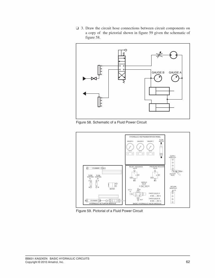
q 3. Draw the circuit hose connections between circuit components ona copy of the pictorial shown in figure 59 given the schematic offigure 58.
BB831-XA02XEN BASIC HYDRAULIC CIRCUITSCopyright © 2010 Amatrol, Inc. 62
GAUGE AGAUGE B
Figure 58. Schematic of a Fluid Power Circuit
HYDRAULIC INSTRUMENTATION PANEL
GAUGE A GAUGE B GAUGE CFLOWMETER
SUPPLYMANIFOLD
RETURNMANIFOLD
BASIC HYDRAULIC VALVE MODULE
1
2
3
1
2
3
A B
B A
B A
A B
IN
OUT
RELIEF \ SEQUENCEVALVE
PRESSURE REDUCINGVALVE
VALVE
CHECK VALVE #1
CHECK VALVE #2
D.C.V.#1
NEEDLE
HYDRAULIC ACTUATOR MODULE
CYLINDER
A
B
A
B
CYLINDER
FLOWCONTROL
#1
FLOWCONTROL
#2
MOTOR
SHUTOFFVALVE
Figure 59. Pictorial of a Fluid Power Circuit

SKILL 7 DESIGN A MULTIPLE ACTUATOR HYDRAULIC CIRCUIT
q 1. Read the following scenario.
Scenario: You work for a company that builds plastic injectionmolding machines. Your job is to design a hydraulic circuit thatwill perform the following operations:
• Open and close a mold with a hydraulic cylinder.
• Power a hydraulic motor to turn a large screw that feeds hotplastic into the mold.
The motor and the cylinder should be capable of operatingseparately, but the motor should only be able to turn when themold is clamped (cylinder extended). The speed of both thecylinder and the motor must be separately adjustable.
A pressure gauge should be located near each actuator.
The motor only needs to turn in one direction.
You can use more than one directional control valve if needed.
Use lever operated DCV’s.
BB831-XA02XEN BASIC HYDRAULIC CIRCUITSCopyright © 2010 Amatrol, Inc. 63
Procedure OverviewNow that you have learned how to draw schematics,
you will get a chance to combine this skill with yourcreativity to design a more complex hydraulic circuit.
A. HYDRAULICCLAMP
CYLINDER BC
D
E
F
G
JL
N
H. HYDRAULIC MOTORDRIVE
Figure 60. Plastic Injection Molding Machine
A. Hydraulic clamp cylinderB. Movable platenC. Mold halvesD. Fixed platenE. Injection nozzle
F. Heating cylinder andreciprocating screw
G. Hopper for Plastic PelletsH. Hydraulic Screw drive
Oil pressure:J. Screw forwardL. ClampN. No pressure
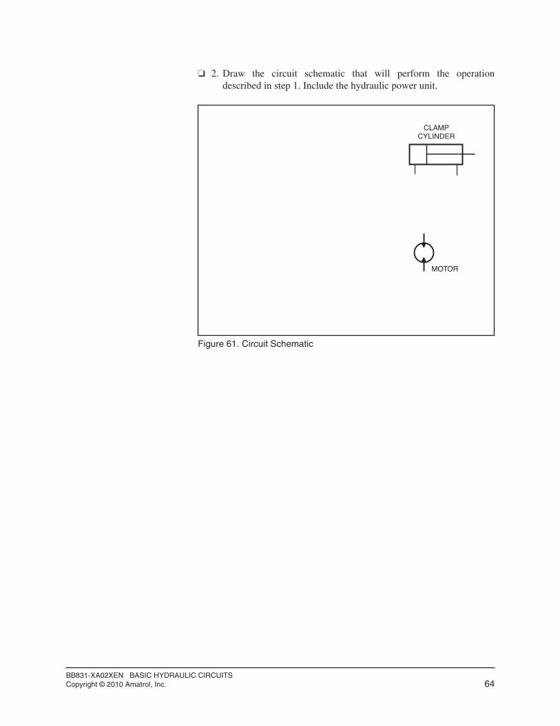
q 2. Draw the circuit schematic that will perform the operationdescribed in step 1. Include the hydraulic power unit.
BB831-XA02XEN BASIC HYDRAULIC CIRCUITSCopyright © 2010 Amatrol, Inc. 64
MOTOR
CLAMPCYLINDER
Figure 61. Circuit Schematic

SEGMENT 4 SELF REVIEW
BB831-XA02XEN BASIC HYDRAULIC CIRCUITSCopyright © 2010 Amatrol, Inc. 65
1. Unless specifically mentioned, schematic symbols are drawn in the ______________ condition.
2. The one symbol which may be shown many times on aschematic but does not mean that there are more than one isthe __________________.
3. The letter M inside of a circle indicates ____________.
4. Symbols may be rotated or reversed except for the ________________ which is always shown with an open side up.
5. An X across a conductor or connector indicates that it is _________________.