basic (electronic) experiments for nuclear engineersweb.khu.ac.kr/~kpark/basic_exprts/basic...
TRANSCRIPT

C O U R S E B O O K ( P A R T 1 )
D E P A R T M E N T O F N U C L E A R E N G I N E E R I N G K Y U N G H E E U N I V E R S I T Y
K W A N G H E O N P A R K
Basic (Electronic) Experiments for Nuclear Engineers
1

2
-GM Counter

Grade: Experiment note (30%), Mid-term (20%), Final (20%), Reports(HW) (15%), Aduino (10%), Attendance (5%)
Text: Dave Cutcher, ‘Electronic Circuits for the Evil Genius,’ Mc Graw HillPaul Scherz, ‘Practical Electronics for Inventors,’ 2nd ed. Mc Graw Hill
3
Lesson Exp Week Content Experiment Homework Aduino
3/7 3/9 1 (1) Introduction, Class schedule, Precautions, charge, electric current, voltage, electric circuit - Blinking a LED
3/14 3/16 2 (2) Ohm's Law, Digital Multimeter, Resistor, LDR, Diode 1,2,3 Traffic Light
3/21 3/23 3 (3) Kirchhoff's Law, Resistor, Capacitor, Introducing Excel 4,5,6 1,2 Alarm
3/28 3/30 4 (4) NPN, PNP Transistor 7,8,9 3,4 Temperature Alarm
4/4 4/6 5 (5) Digital logic, AND, OR, NAND, NOR Gates, CMOS IC 10,11 Detecting Vibration
4/11 4/13 6 MidTerm (Election)
4/18 4/20 7 (6) LabView and Data Acquisition 12 Auto Light
4/25 4/27 8 (7) NAND gate oscillator 13 5 Moving a Servor
5/2 5/4 9 (8) AC and DC, Amplifier, Oscilloscope 14,15,16 6 Motor Fan
5/9 5/11 10 (9) OP amp - Feedback circuit 17,18 7 Interact with Servo
5/16 5/18 11 Review
5/23 5/25 12 (10) Dosimetry by a GM Counter 19 8,9 LED Matrix
5/30 6/1 13 (10) Dosimetry by a GM Counter (continue) 20,21 10 Bluetooth Module
6/6 6/8 14 (10) Dosimetry by a GM Counter (continue) 22,23 Self guided Problem
6/13 6/15 15 Review
6/20 6/22 16 Final

Fundamental Concepts.
Text: Dave Cutcher, ‘Electronic Circuits for the Evil Genius,’ Mc Graw HillPaul Scherz, ‘Practical Electronics for Inventors,’ 2nd ed. Mc Graw Hill
1-1

1. Charge:Ordinary matter is made up of atoms which have positively charged nuclei and negatively charged electrons surrounding them. Charge is quantized as a multiple of the electron or proton charge ( ).Unit= C (coulomb)
191.602 10 Coul
Fundamental Concepts.
1-2
-1C = 6.242x10¹⁸ electrons
Free electrons
Conductor Insulator
Valence electrons

1-36

2. Electric current:The total charge that passes through a conductor per unit time.Unit= A(ampere) = 1 C/s (coulomb per sec)
1-4
From now on, we consider positive charges are moving along the directionof current, which is wrong, however, which is convenient to think over.
7

3. Voltage:Electromotive force that is responsible for giving all free electrons (or ions)within the conductor a push to move.Unit= V (volt)
Electrical Battery:chemical driving force = electromotive force.
1-58

V+: Appliedvoltage
Current
Water flow:Current
Hydrostatic Potential:Voltage
1-69

1-710

4. Electrical circuit:An electrical circuit is a network that has a closed loop, giving a return path for the current.
1-811

5. Ground, the earth (reference)
Ground (earth), the reference as V=0 volt.
1-912

6. Ohm’s law: ( https://youtu.be/GwxFfWS4vyc )
Free electrons in a material undergo frequent collisions with other electrons, lattice ions, and impurities within the lattice that limit their forward motion.These mechanisms impede electron flow with electrical resistance. Resistance is the ratio of the applied voltage divided by the resultant currentflow.
or,
The unit of resistance, .
11V / 1A
VRI
( )ohm
V I R
7. Energy:The total work that 1 C of charge moves along 1 V of electromagnetic forceis 1 Joule.
1 Joule = 1 V x 1 C
8. Power:Energy per second used by a device such as a resistor.
22( / sec) ( ) VP joule P watt V I I R
R
2-113

2
2
2-2
2
2
14

2-3
2
2
15

2-416

Resistors in series: R4R3R2R1
1 2 3 4TotR R R R R
Resistors in parallel:
R4R3R2R1
1 2 3 4
1 1 1 1 1
TotR R R R R or,
1 2 3 4
11 1 1 1TotR
R R R R
2-517

2-618

9. Digital Multimeter
Measure voltage, resistivity (impedance), current.
2-719

2-820

10. Diode
Diode is a one-way street. Diode lets current flow only in one direction.
Power diodeLED (Light Emitting Diode)
Negative(cathode)
2-921

2-1022

Experiment 1. Preparation.
a) The solderless breadboard has a definite layout as shown in the figure.One strip of the spring metal in the breadboard connects the five holes.You can easily connect five pieces in one strip. Please draw lines wherethe holes are commonly connected.
b) You will be given 5 resistors that were known to have the same resistance.Measure the resistance of each resistor and record it. Find the average value and the standard deviation.
23

Experiment 2. Start to make a basic electronic circuit.Purpose: The summation of each voltage at all components in a circuit
equals to the total voltage applied to the circuit.Setup the following circuit on your breadboard.
Parts Spec. No./ea
9V Battery cell 1
Safety diode IN4003 1
Resistor 470 Ohm 1
LED 1
24

http://www.play-hookey.com/
25

Experiment 2 (cont.)Let's look at how the voltage is being used in the circuit. Set the Digital Multimeter(DMM) to direct-current voltage (DCV).
a) Measure the voltage of the 9-volt battery while it is connected to the circuit.Place the red (+) probe at test point A (TP-A) and the black (-) probe atTP-D (ground). The arrows in the schematic shown in Figure indicate where to attachthe probes.Record your working battery. voltage. _____V
b) Measure the voltage used between the following points:TP-A to TP-B across the safety diode: _____VTP-B to TP-C across the 470-ohm resistor: _____VTP-C to TP-D across the LED: _____V
c) Now add all the voltages from b): _____V
d) Compare the voltage used by all of the parts to the voltage provided by the battery.The voltages added together should be approximately the same as the voltageprovided by the battery. It may be only a few hundredths of a volt difference.
e) Describe why there is a difference between two total voltages.
26

R1=470 ohmR2= 1 kohmR3=470 ohmR4= 1 kohm
R4R3
R2
R1
A B
C
D E
Experiment 3. Ohm’s law conformation.Purpose: Application of Ohm’s law for the analysis of a circuit.
a) Measure the resistance of R1, R2, R3, R4 by DMM. Check the accuracy.
Now, set up the circuit on the breadboard.
b) Measure the resistance connected in series (RACD) and that in parallel (RBE). Be sure of that the connection that you are going to measure should be isolated. After setting up total connection, measure the total resistance. Check whether Ohm’s law is applicable.
c) Measure the voltage across each resistor.
d) Calculate the value of current passes through each resistor.
e) Calculate the power generated by each resistor.
f) Compare the sum of all powers generated by each resistorand the power calculated from the total resistance.
22 VP I V I R
R
27

11. Resistors ( https://youtu.be/ETxe--h4u40 )
3-128

① 10Ⅹ105Ω=1MΩ ±5%② 68Ⅹ103Ω=68kΩ ±5%③ 51Ⅹ102Ω=5.1kΩ ±5%
① ② ③
?3-229

12. Open circuit, short circuit
3-330

13. Capacitor ( https://youtu.be/2F2vJr47AkY )
A capacitor can store an electric charge. The capacitor is made of just twoMetal plates with a bit of insulation between them. The amount of chargea capacitor can store is proportional to the voltage applied. Capacitance ofa capacitor is defined by,
( )( )( )
Q coulombC F faradV volt
61 ( ) 1 10F microfarad F 121 ( ) 1 10pF picofarad F
3-431

• 금속판
• 금속판
• 유전체
Metal foil
insulator
( 47x103pF, 5%)
( 33x103pF, 10%)
( 10x104pF )
3-532

3-633

Capacitors can be connected in serial and/or in parallel.
Capacitors in parallel:
C1 C2 C3 C4
C1 C2 C3 C4Capacitors in series:
1 2 3 4TotC C C C C
1 2 3 4
1 1 1 1 1
TotC C C C C
1 2 3 4
11 1 1 1TotC
C C C C
3-734

Experiment 4Purpose: Role of Capacitor as a charge storage.
a) Set up the circuit on the breadboard. Look closely at the electrolytic capacitors. Be sure to note the stripe and the short leg that marks the polarity.
b) Describe what happens in your circuit as you push the button, then let go.
c) (1) Disconnect the wire between the capacitor and R1 (point A).(2) Push the button to charge the capacitor.
Now wait for a minute or so.(3) Set your DMM to the proper voltage range. Put the red probe
to the positive side of the cap, and the black probe to ground. Record the voltage that first appears. The capacitor will slowly leak its charge through the DMM.
(4) Reconnect the wire and describe what happens.
d) Use the following Table to record your information as you play with your circuit. As you replace each capacitor and record the time, the LED stays on. Don't expect the time to be very exact.
Capacitor value Time
1,000 microF
470 microF
100 microF
Ax
R1=470 OhmC1= 1000 microF
35
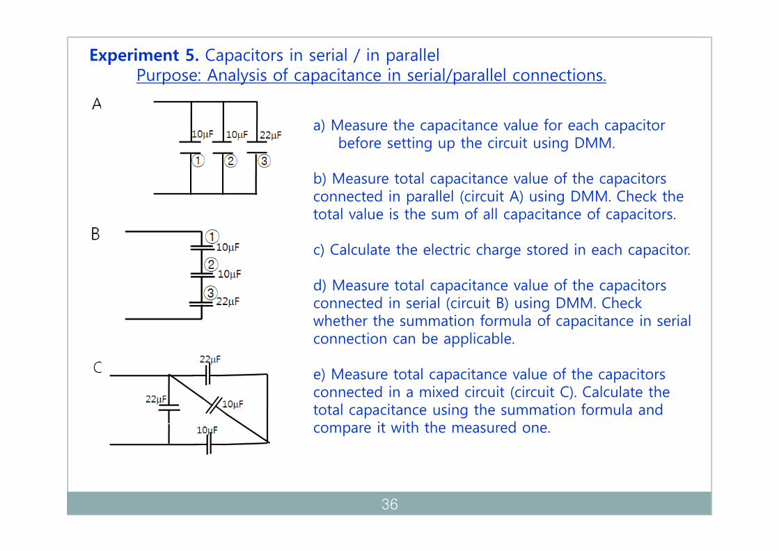
Experiment 5. Capacitors in serial / in parallelPurpose: Analysis of capacitance in serial/parallel connections.
a) Measure the capacitance value for each capacitor before setting up the circuit using DMM.
b) Measure total capacitance value of the capacitors connected in parallel (circuit A) using DMM. Check the total value is the sum of all capacitance of capacitors.
c) Calculate the electric charge stored in each capacitor.
d) Measure total capacitance value of the capacitors connected in serial (circuit B) using DMM. Check whether the summation formula of capacitance in serial connection can be applicable.
e) Measure total capacitance value of the capacitors connected in a mixed circuit (circuit C). Calculate the total capacitance using the summation formula and compare it with the measured one.
36

14. Kirchhoff’s Law
Voltage law (or loop rule): The algebraic sum of the voltages around any loop of a circuit is zero.
1 2 3 0NV V V V V
3-837

Current law (or junction rule): The sum of the currents that enter a junctionequals the sum of the currents that leave the junction.
in outI I
1 2 3I I I
3 4 6I I I 2 4 5I I I
3-938

Example
In a matrix form (multivariable-linear equations),
3-10
6 variables, 6 equations
39

AX Y
A X Y where,
where, 1A Inverse matrix of A I
1 1A AX I X X A Y
3-1140
‘Office Excel’ is very useful and powerful.
Usage of Excel1. Spread sheet – make tables, cells, reports, etc..2. Draw graphs and charts.3. Calculation tool – easy and powerful.
Calculation Tools – examples.1. Basic calculations in Excel2. Solution of equations:
- one variable, non-linear equation.- multivariable linear equations
Exl-141

Basic calculations
Exl-242

Linear Least Squares Fitting
Exl-343

Excel Equation Solver
Setting up.
Exl-444

Solution of non-linear single variable equation
solution of2 3 4 0x x
Exl-545

Solution of linear multivariable equations
then,AX Y 1 1A AX I X X A Y
Exl-646

Matrix
11 12 13
21 22 23
31 32 33
a a aa a aa a a
1st row2nd row3rd row
3rd
colum
n
2nd
colum
n
1stco
lumn
ija ith row jth column
11 12 13 11 12 13 11 11 12 21 13 31 11 12 12 22 13 32 11 13 12 23 13 33
21 22 23 21 22 23 21 11 22 21 23 31 21 12 22 22 23 32 21 13 22 23 23 33
31 32 33 31 32 33 31 1
a a a b b b a b a b a b a b a b a b a b a b a ba a a b b b a b a b a b a b a b a b a b a b a ba a a b b b a b
1 32 21 33 31 31 12 32 22 33 32 31 13 32 23 33 33a b a b a b a b a b a b a b a b
Matrix multiplication AB C1
N
ij ik kjk
c a b
2 3 1 1 11 41 4 3 2 13 7
Example:1 1 2 1 3 1 5 6 82 1 1 2 1 1 3 6 01 3 2 1 1 3 5 4 2
1 2 1 1 1 42 1 4 2 2 241 1 3 2 3 162 1 2 1 4 2
N K K M N M
1 0 2
1 1 2 0 1 1 5 7 12 4 0
Supplementary
A
47 Exl-7

Unit matrix
1 0 0 1 2 1 1 2 10 1 0 1 1 3 1 1 30 0 1 0 2 4 0 2 4
I A AI AI A
4 2 1 1 0 0 4 2 12 1 3 0 1 0 2 1 31 2 1 0 0 1 1 2 1
Inverse matrix 1A 1AA I 1A A I
2 2 3 1 1 3 1 0 03 1 3 0 2 3 0 1 02 1 2 1 2 4 0 0 1
1 1 3 2 2 3 1 0 00 2 3 3 1 3 0 1 01 2 4 2 1 2 0 0 1
1 0 0 2 20 1 0 1 10 0 1 4 4
Supplementary
1 2 1 0 1 1 1 0 01 1 1 1 1 0 0 1 00 1 1 1 1 1 0 0 1
48 Exl-8

Homework 1. You have learned Kirchhoff’s law for the analysis of a circuit. Find total current (i.e., the current passes through R1) in the circuit below. And compare the result with that from the calculation based on Ohm’s law.
V
49

Experiment 6 Purpose: Application of Kirchhoff’s law for the analysis of a circuit.
We are going to setup the following circuit on the breadboard.
a) Before setting up, measure the resistance of each resistor and check the accuracy.b) After setup, measure the voltage across each resistor.c) Find out the current passes through each resistor.d) Analyze the circuit and calculate the current passing through each resistor
using Kirchhoff’s law (Use Excel program to get the solution). Compare the values of the currents from the calculation and those from the measurements.
R1= 470 ohmR2= 1 kohmR3= 2.2 kohmR4= 470 ohmR5= 4.7 kohmR6= 1 kohm
50

Homework 2. A circuit called Wheatstone bridge is technically important in measuring the unknown resistance of a resistor. Explain the principles of Wheatstone bridge by applying Kirchhoff’s law.
51

15. Transistor ( https://youtu.be/Cr6bHNrdNp0 )
NPN transistor: semiconductor devices that act as either electrically controlled switchesor amplifier controls.
The arrow inside the symbol.-the direction of the current towards ground-always on the side of the emitter.
The NPN transistor is turned on when a positive voltage is applied to the base.The NPN transistor acts very much like a water faucet. A little pressure on thehandle opens the valve, releasing the water under pressure.
4-1
N
P
N
52

High PressureWater
HighCurrent
ControlValveby VBEHigh Pressure
Water
ControlValve
4-253

An NPN transistor control current flow through a lightbulb. When a positive voltage is applied to the base,the collector-to-emitter channel opens, allowing currentto flow from Vcc through the light bulb and into ground.
Transistors are operated in the active region. Small amount of base current changes large amount of collector current. For example, 0.3mA of base current results 10mA of collector current. So, a little pressure (voltage) on the base of the NPN transistor leads to a very large increase in the flow of current through the NPN transistor from the collector to the emitter.
4-3
Increasing VBE
VBEB
E
C
54

(a) Basic common-emitter amplifier circuit. (b) Transfer characteristic of the circuit in (a). The amplifier is biased at a point Q, and a small voltage signal vi is superimposed on the dc bias voltage VBE. The resulting output signal vo appears superimposed on the dc collector voltage VCE. The amplitude of vo is larger than that of vi by the voltage gain Av.
VBE
VCE
VBE (V)
VCE
4-455

Experiment 7. NPN transistor demonstration circuit.Purpose: Role of the base voltage to the emitter current in NPN transistor.
Setup the following circuit on the breadboard.
a) Press and release the push button. After you release the push button, what part provides the power to the base of the transistor?
b) Describe the path of the current that provides the power to the LED. Is the capacitor powering the LED?
c) Record three time trials of how long the LED stays on with the 10 microF capacitor. Find the average.
d) Replace C1 with 100 microF capacitor. Time the LED here for three times as well and find the average. Roughly, how much more time did the 100 microF capacitor keep the LED on than 10 microFcapacitor?
e)Write down your prediction of how much time the 1000 microFcapacitor would keep the LED working? And check the estimation by trying it using 1000 microF capacitor. How accurate was your prediction? Can you make a relation between the LED light emitting time and capacitance?
C1= 10 micrFR1= 22 kOhmR2= 470 Ohm
56

Homework 3
a) Briefly describe the purpose of the transistor.
b) There are many transistors that look different. Draw some of them, and indicate Emitter, Base, and Collector to the three legs.
c) What two separate things does the arrow inside the transistor symbol indicate?
d) Regarding the water faucet analogy, is the water pressure provided by the water system or the handle?
57

15. Transistor (continue)
PNP transistor:
N
P
PThe PNP transistor’s action is opposite of the NPN. As you increase the voltageto the base, the flow decreases; and as the voltage to the base decreases, thePNP transistor is turned on more. The PNP transistor still acts very much like a water faucet. A little pressure on the handle closes the valve, stopping the water.
The arrow inside the symbol still points in the direction of the current , but is on the top side.PNP emitters and collectors have reversed positions relative to the NPN.
4-558

In PNP transistor circuit, everything is reversed to that of the NPN.Current must leave the base in order for a collector current to flow.
4-659

Experiment 8. PNP transistor demonstration circuit, 1st Example.Purpose: Role of the base voltage to the collector current in PNP transistor.
Setup the following circuit on the breadboard.
a) When you first attach your battery, check whether LED turns on immediately. Why does LED turn on initially?
b) Press and release the push button. What happens to LED? Describe the path of the current that provides the power to the LED.
c) Record three time trials of how long it takes till the LED turns on fully with the 100 microF capacitor. Find the average.
d) Replace C1 with 1000 microF capacitor. Time the LED here for three times as well and find the average. Roughly, how much more time did the 1000 microF capacitor need for the LED to light on than 100 microF capacitor?
e) Replace R1 with 1 MOhm resistor and let C1 be 100 microF. Measure roughly how much time is needed to make LED turn on fully.
C1= 100 micrFR1= 100 kOhmR2= 22 kOhmR3= 470 Ohm
60

Experiment 9. PNP transistor demonstration circuit, 2nd Example.Purpose: Measurement of DC current gain of a PNP transistor.
Setup the following circuit on the breadboard.
a) When you first attach your battery, check whether LED turns on immediately. Measure the voltage at point A with respect to the ground.
b) Measure the voltage between points AD (VAD) and points FG (VFG).
c) Calculate the current through R3 (IB) and that through R4 (IC), respectively. Find DC current gain, i.e., the ratio, IC / IB .
d) Replace R1 with 10 kOhm. Measure the voltage at point A again.
e) Measure the voltage between points AD (VAD) and points FG (VFG).Calculate the current through R3 and that through R4, and find the DC current gain (i.e., IC / IB ).
f) Replace R1 with 20 kOhm (connect two 10 kOhm resistors serially).Measure the voltage at A, and find the DC current gain.
g) Find the average DC current gain.
R1= 47 kOhmR2= 10 kOhmR3= 22 kOhmR4= 470 Ohm
Ax x
x
x
D
F
G
61

Homework 4
Find and write down the definition of ‘DC current gain’ (hFE or ) of a transistor. You can find the data sheet for ‘2n3906’ PNP transistor easily by web searching. Compare the measured current gains in Experiment 9 with the values in the data sheet.
62

16. Digital Logic ( https://youtu.be/V3z-N1VHgOM )
Digital electronics deals with only two things; on/off (or 0/1, low/high, …).By combination of these two things, you can store, transfer, and makemeaningful information.
Binary system (0,1):
Decimal system (0,1,2,3,4,5,6,7,8,9):
A byte is a basic unit of measurement of information storage in computer science. In many computer architectures it is a unit of memory addressing. There is no standard but a byte most often consists of eight bits.
10011101 8 bit/ 1 byte
7 6 5 4 3 2 1 010011101 1 2 0 2 0 2 1 2 1 2 1 2 0 2 1 2
7 6 5 4 3 2 1 045623907 4 10 5 10 6 10 2 10 3 10 9 10 0 10 7 10
5-163

Binary alphabet: ASCII table
Space= 20 = 00010100A = 65 = 01000001 a = 97 = 01100001B = 66 = 01000010 b = 98 = 01100010
Y = 89 = 01011001 y = 121 = 01111001 Z = 90 = 01011100 z = 122 = 01111010
5-2
Digital electronic system:Information is combinations of only two things, i.e., High or Low; 1 or 0; On or Off; Yes or No;….
Time set by Clock
H H L L H H L H H1 1 0 0 1 1 0 1 1
+V
-V
0
64

Analog Digital
advantage
Varying voltages. Precise transfer of information.
Easy to record. No generational loss.
Easy to play back. Footprint of a bit can be done at the molecular level.
Common transfer rate in billion bits per second.
Any material can be used for storing data. (0/1, high/low, on/off)
Disadvantage
Not precise. Needs special equipment to transfer, record, and read information.
Signal loss with each generation recorded.
Take up large recording space.
Limited transfer time.
Signal fades as media ages.
5-365

17. AND, OR, NAND, NOR Gates
AND Gate:
input A input B Output
High High HighHigh Low LowLow High LowLow Low Low
5-466

OR Gate:
input A input B Output
High High HighHigh Low HighLow High HighLow Low Low
5-567

NOT Gate:
N T input Output
High LowLow High
5-668

NAND Gate:
input A input B Output
High High LowHigh Low HighLow High HighLow Low High
If any one of inputs is ‘low’,the output is ‘High’.
5-769

input A input B Output
High High High
High Low High
Low High High
Low Low Low
input A input B Output
High High Low
High Low High
Low High High
Low Low High
input A input B Output
High High High
High Low Low
Low High Low
Low Low Low
input A input B Output
High High Low
High Low Low
Low High Low
Low Low High
AND Gate OR Gate
NAND Gate NOR Gate
5-870
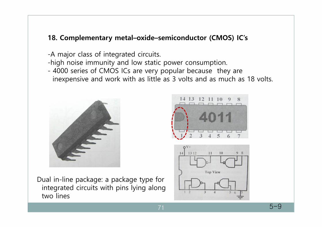
18. Complementary metal–oxide–semiconductor (CMOS) IC’s
-A major class of integrated circuits.-high noise immunity and low static power consumption.- 4000 series of CMOS ICs are very popular because they are
inexpensive and work with as little as 3 volts and as much as 18 volts.
Dual in-line package: a package type forintegrated circuits with pins lying along two lines
5-971

Precautions for CMOS ICs
- CMOS IC’s are static sensitive.
- Always store the IC in a carrying tube or static foam until it is placed into the circuits.
- Remove static from your fingers. Touch some type of large metal object to remove any static electricity from your fingers before you handle the CMOS chips.
- Always check that the chip is set in properly. (cautious about numbering).
- Don’t walk across the room with a CMOS chip in hand.
- Always tie any unused inputs to ground. If an input is not connected, the small voltage changes in the air around us can affect the input.
5-1072

Experiment 10. NAND logic conformation.Purpose: Check the NAND gate output.
Setup the following circuit on the breadboard.Be careful about numbering the legs of the 4011 IC chip.We use only legs, 1, 2, and 3. The other input legs (5, 6, 8, 9, 12, 13) should be grounded.
a) Measure the voltages (VA, VC) at points, A and C. If the voltage is higher than V/2, we call it is ‘High’. Otherwise, it is ‘Low’. Remember we are studying digital logic. Which ones are high and which ones are low?
b) Apply High voltage (VA) to point D and Low voltage (VC) to point E. Check whether LED turns on. Remove the LED, then measure the voltage at point F. c) If we apply High voltages to both inputs (points D and E), what happens? Measure the output voltage at point F.
d) By changing high and low voltages applied to points D and E, check NAND logic by filling up the following table.
R= 10 kOhm
73

Experiment 11. Analog and Digital Combination.Purpose: Understanding the analog and digital combination circuit.
Set up the following circuit on your breadboard. Be careful about numbering the legs of the IC chip. Unused inputs are recommended to be grounded. Notice the test points (TP) 1, 2, 3, and 4. When you push the button, LED will light for a while then turn itself off, if all parts are successfully connected.a) Measure the voltages at TP1, TP2, TP3, and TP4 before you push the button. b) Measure the voltages at TP1, TP2, TP3, and TP4 while you are pushing the button.c) Measure the voltages at TP1 and TP2 after you release the button.d) Observe the voltage change at TP3 after you release the button. If possible, record the voltage change with time. Measure how long LED turns on.
e) After you release the button, LED turns on for a while. Observe the voltage at TP3, then record the voltage when LED turns off. Is it the half of 9V?f) Change C1 and R2 as shown in the table below. First, expect the time for which LED turns on. And measure the real time for which LED is on.
R1= 100 kOhmR2= 220 kOhmC1= 100 microF
74

75