basic design study report on the project for the
TRANSCRIPT

BASIC DESIGN STUDY REPORT
ON THE PROJECT
FOR
THE IMPROVEMENT
OF
NATIONAL HIGHWAY N-25
IN
ISLAMIC REPUBLIC OF PAKISTAN
JULY 2005
JAPAN INTERNATIONAL COOPERATION AGENCYGRANT AID MANAGEMENT DEPARTMENT
No.
J R
05-111
G M

PREFACE
In response to a request from the Government of the Islamic Republic of Pakistan, the
Government of Japan decided to conduct a basic design study on the Project for the Improvement of
National Highway N-25 in the Islamic Republic of Pakistan and entrusted the study to the Japan
International Cooperation Agency (JICA).
JICA sent to Pakistan a study team from January 8th to February 26th, 2005.
The team held discussions with the officials concerned of the Government of Pakistan, and
conducted a field study at the study area. After the team returned to Japan, further studies were
made. Then, a mission was sent to Pakistan in order to discuss a draft basic design, and as this result,
the present report was finalized.
I hope that this report will contribute to the promotion of the project and to the enhancement
of friendly relations between our two countries.
I wish to express my sincere appreciation to the officials concerned of the Government of the
State of Eritrea for their close cooperation extended to the teams.
July , 2005
Seiji Kojima
Vice-President
Japan International Cooperation Agency

July, 2005
Letter of Transmittal
We are pleased to submit to you the basic design study report on the Project for the
Improvement of National Highway N-25 in the Islamic Republic of Pakistan.
This study was conducted by the joint venture between Construction Project Consultants, Inc.,
and Nippon Koei Co., Ltd., under a contract to JICA, during the period from December, 2004 to
July, 2005. In conducting the study, we have examined the feasibility and rationale of the project
with due consideration to the present situation of Pakistan and formulated the most appropriate
basic design for the project under Japan’s grant aid scheme.
Finally, we hope that this report will contribute to further promotion of the project.
Very truly yours,
Shozo Inoue
Project Manager
Basic design study team on the Project for
the Improvement of National Highway
N-25 in the Islamic Republic of Pakistan
The joint venture between
Construction Project Consultants, Inc.
and Nippon Koei Co.,Ltd.

International Border
Provincial Border
Trunk Road
Pakistan
LOCATION MAP
0 100 200 300
km
Wadh
Kararo
Objective Road
N
N
National Capital
Province City

PE
RS
PE
CT
IVE

List of Tables
Table 2.1 Options for Geometric Structure of the Road .........................................................11
Table 2.2 Options for Pavement Structure ..............................................................................13
Table 2.3 Evaluation Standard for Bridge Damage ................................................................15
Table 2.4 Evaluation Standard for Bridge Load Bearing Capacity.........................................15
Table 2.5 Evaluation Standard for Culvert Damage ...............................................................15
Table 2.6 Evaluation Standard for Culvert Functionality .......................................................16
Table 2.7 Summary of Elements to be considered..................................................................19
Table 2.8 Evaluation of alternatives for the selection.............................................................21
Table 2.9 Items to be rehabilitated in the project....................................................................22
Table 2.10 Improvement work of each design section ...........................................................24
Table 2.11 Design speed for each design section....................................................................25
Table 2.12 Minimum radius and maximum incline for each design speed.............................26
Table 2.13 Outline of Design Condition .................................................................................28
Table 2.14 Section-wise traffic and standard axle load per vehicle type ................................29
Table 2.15 Test Result on Material and bearing strength of the existing road........................30
Table 2.16 Traffic Sign Design Plan.......................................................................................31
Table 2.17 Design Standard for Transversal Drainage Facilities............................................32
Table 2.18 Mode of Rehabilitation for Target Culverts ..........................................................33
Table 2.19 Mode and magnitude of replacement for the target culverts.................................34
Table 2.20 Mode and magnitude of rehabilitation for the culverts to be widned ...................36
Table 2.21 Summary of Quality Control.................................................................................45
Table 2.22 Procurement Countries for Major Materials .........................................................46
Table 2.23 Procurement Countries for Construction Machines..............................................46
Table 2.24 Implementation Schedule......................................................................................47
Table 2.25 Work Items Assigned to Pakistan..........................................................................48
Table 2.26 Estimated Project Cost (to be borne by Japan) .....................................................51
Table 2.27 Summary of Operqation & Maintenance Cost......................................................52

List of Figures
Figure 2.1 Standard Cross-section of Road Plan ....................................................................12
Figure 2.2 Standard Cross-section of Pavement Plan .............................................................13
Figure 2.3 Flow chart of basic concept on building structure repair ......................................17
Figure 2.4 Existing Condition and Feature of the Project Road .............................................20
Figure 2.5 Outline of selected project scope...........................................................................22
Figure 2.6 Basic sectional view of road..................................................................................27

Abbreviation
GDP : Gross Domestic Product
NHA : National Highway Authority
PRSP : Poverty Reduction Strategy Paper
IMF : I nternational Monetary Fund
JICA : Japan International Cooperation Agency
ADB : Asian Development Bank
AC : Asphalt Concrete
HDM-4 : Highway Development and Management System-4
BOT : Build Operate Transfer
AADT : Annual Average daily Traffic
F/S : Feasibility Study
PC-1 : Project Concept -1
RC : Reinforced Concrete
UNDP : United Nation Development Programme
EIA : Environmental Impact Assessment
IEE : Initial Environmental Evaluation
ROW : Right of Way
WB : World Bank
AASHTO : American Association of State Highway and Transportation Officials
CBR : California Bearing Ratio
DBST : Double Bituman Surface Dressing
E/N : Exchange of Note
CAD : Computer Aid Design
AP : Authorization to Pay

- 1 -
Summary Pakistan has a population of 150 million and has a coastline of 800 km on the Arabian Sea.
The country borders Iran and Afghanistan to the west and north, and India and China to the
east and north. The land area is 796 thousand km2, which is approximately twice as large
as that of Japan. There are mountains of over 7000 m in the north of the country and the
Indus River originates in these mountains flowing into the Arabian Sea through the center
of the country. In the west of the country lies Balochistan plateau where the target road for
this project (National Highway 25) runs through, and there is fertile Indus plain in the east,
exhibiting a contrasting natural environment.
The transportation sector in Pakistan is composed of the four modes of road, railway,
aviation, and navigation. It is one of the important industrial sectors that accounts for 10%
of GDP and creating about 2 millions of employment. While road and railway traffic are
the major means of transportation, the ratio of road transportation is increasing, with its
present ratio of 95% in passenger transport and nearly 90% in freight transport. The
number of registration of vehicles is also on the rise at a rate of 8 % per annum and the
total registration is over 5 million at present. The total length of roads in the country is
approximately 250,000 km of which 60 %, corresponding to 160,000 km, is paved. The
National Highway Authority (NHA) manages 19 national highway routes. The total length
of these routes is 9,252 km. Although its figure accounts for only 3.5 % of the national
total, these roads are responsible for 80 % of the total passenger and freight traffic.
The Poverty Reduction Strategy Papers (PRSP), which were released in December 2003
and corresponding to the Five-Year Plan in the past, puts improvement of infrastructure as
one of the important elements to accelerate the economic growth that is an indispensable
factor to poverty reduction. In the papers, especially the road sector is described as
requiring appropriate means of rehabilitation and maintenance in consideration of the
future demand. In response to this situation, NHA of Pakistan, an agency under the
Ministry of Communication, placed the optimum use of existing road system by
rehabilitation and maintenance as one of the priority measures to cope with the problem of
deteriorated existing roads (50 % of the National Highway is in poor condition). In the
five-year mid-term investment plan for 2005/2006 – 2009/2010 prepared in line with the
measures above, the measure is mainly of rehabilitation of existing roads. The

- 2 -
rehabilitation of the section between Kararo-Wadh, the target road section for this project is
also included as one of the newly planned improvement work.
The target section of the road for this project, Kararo-Wadh section is a portion of the
National Highway 25. The highway 25 is growing in its importance as the sole trunk road
passing from north to south in the province of Baluchistan and also as an international road
connecting the surrounding inland countries such as Afghanistan directly to the port in
Karachi in shortest distance. However, this section of the road contains narrow lanes,
sections with many blind curves, and steep slopes. The situation results in frequent
accidents such as crushes and falling off the road due to over-speeding at curves and trying
to pass other vehicles. NHA is carrying out its own repair work to cope with the problems
but it is essentially nothing more than regular maintenance work. Full-fledged
rehabilitation is difficult for NHA both economically and technically, which is the
bottleneck in the rehabilitation effort. The situation is anticipated to create hindrance to the
Kararo-Wad section of the road and it can eventually cause negative effects on the function
of National Highway 25. The rehabilitation of this section is, thus, considered necessary
and urgent. Under these circumstances, in 2003, the government of Pakistan requested
Japan’s grant aid assistance on the improvement of traffic safety in the road section (96
km) including widening of the road to 7.3 m, amelioration of sharp curves and steep slopes,
and improvement of drainage structures.
The government of Japan, in response to this request, decided to conduct a basic design
study. JICA undertook the study and dispatched a study team for the basic design study
starting from 8th
January to 26th
February 2005 and the team conducted a field
investigation of the 96 km – section requested for improvement. The study team, through
discussions with Pakistani side, reached a consensus with NHA that the rehabilitation work
should limit to sections and work items requiring urgent measures by Japan’s grant aid and
exclude portions of work that could be handled by the Pakistani side. After returning to
Japan, the study team determined the scope of work for the grant aid assistance as shown
below on the basis of the results of the field investigation.

- 3 -
Imprivement items for the plan Contents of plan 1) Road improvement section
1-1) Roadway -Design speed
Alignment conditions -Pavement width -Pavement structure
1-2) Road shoulder -Road shoulder width -Pavement structure
2) Section for minor improvement
44.8km 60km/h(mountains and hills) Minimum radius of curve (135m), Maximum slope (7%) 7.3m(3.65 m x 2 lanes) Asphalt concrete 12 cm (surface 5cm, base 7cm) Base course: 20cm Sub base course 27cm
Standard 2.0 m(Min1.0m) Surface(double bituminous surface treatment DBST) Base course (Sub base course material) 59 cm
51.2 km Reshaping road shoulders Road marking lines (center and side lines)
3)Rehabilitation of transversal drainage structures
Reconstruction of 113 culverts Expansion of 12 culverts
4) Auxiliary facilities Drainage and retention :Retention pit, Intake pipe Slope protection :Masonry wall, flat gabion Road sign :103 Guardrail :5,500 m Guard post :300 Edge marker :191 Road marking :Center and side line 96km Kilo-post :97
The items shown in the table above along with other information were integrated in a
report on the basic design study. The study team with the mission of presenting and
explaining this report was dispatched starting 2nd June to 11th June 2005 and made an
agreement with the Pakistani side on the general content of the report.
The study found the period required to implement the project under the scheme of Japan’s
grant aid assistance to be 8.5 months for detailed designing (including tender) and 42
months for construction work. The project cost was estimated to be 4,156 million yen
(Japanese side: 4,113 million yen, Pakistani side : 43 million yen).
There is no construction work allocated to the Pakistani side in this project. However, since
the two parties agreed on the arrangement that the project only focuses on the sections and
items that require urgent rehabilitation by Japan’s grant aid assistance scheme and that the
items and portions of work that can be implemented by the Pakistani side itself have been
excluded, the Pakistani side is expected to realize their rehabilitation plans to promote the
- 4 -
function of the Kararo-Wadh section of the highway as a whole.
The target portion of the road for this project is a section of National Highway 25 that is
the only trunk road that runs through the province of Balochistan in north-south direction.
Implementation of this project is considered to benefit about 7 million of the whole
residents in the province of Balochistan. The following are the expected benefits
determined through the study.
Direct benefits
-The number of traffic accidents will decrease (average number of accident:120 case/
year for 5 years) due to improved road alignment (max. slope reduced from 10 % to 7 %,
min. curve radius reduced from 50 m to 135 m) and improved traffic safety.
-Possible reduction in travel time due to the smooth traffic on improved road with the
average speed of 60km/hr, compared with actual speed restriction of 30km/hr on about
30 places of sharp curves and steep slopes
Indirect benefits
-The National Highway 25 that includes the target section for this project is the National
Highway directly connecting Afghanistan and the central Asia to the Karachi port in
Pakistan. Thus, the implementation of the project, by eliminating the traffic bottleneck in
the international highway, can also help promote the revitalization of Afghanistan that is
rapidly underway.
-Rehabilitation of the road is expected to bring up the number of buses, ambulances and
school buses plying certain routes. This will facilitate transportation to major towns in
the area. As a result, the local people will obtain excellent facilities.
-The area along National Highway 25 within the province of Baluchistan constitutes
large-scale farmland for cash crops such as fruits and vegetables. Especially around
Quetta area, promiculture is widely practiced and the products are exported from the
Karachi port. As in this example, the elimination of the traffic bottleneck in highway 25
will contribute to more rapid and secure transportation of harvested farm products to
Karachi for both consumption and exportation and eventually contribute to facilities of
the local residents.

- 5 -
As described above, this project aims at securing safe traffic by improving the sections
with safety problems along Kararo-Wadh section of the highway. The project directly
contributes to the amelioration of a major highway in the country, which the Pakistani
government requires. In addition, the joint and coordinated realization of the project by
Japan’s grant aid assistance and the work by Pakistani side is expected to strongly
contribute to establishing better relationship between the two countries, which also
confirms validity of the project implementation.

BASIC DESIGN STUDY ON THE PROJECT FOR
THE IMPROVEMENT OF NATIONAL HIGHWAY N-25
Preface
Letter of Transmittal
Location Map/Perspective
List of Tables & Figures
Abbreviation
Summary
TABLE OF CONTENTS Page
Chapter 1 Background of the Project .....................................................................................1
Chapter 2 Contents of the Project ..........................................................................................3
2.1 Basic Concept of the Project..........................................................................................3
2.2 Basic Design of the Requested Japanese Assistance...................................................4
2.2.1 Design Policy ........................................................................................................... 4
2.2.2 Basic Plan ..............................................................................................................18
2.2.3 Drawings for Basic Design ...................................................................................38
2.2.4 Implementation Plan ............................................................................................39
2.3 Outline of Work Assigned to Pakistani Government.................................................48
2.3.1 General Requirements of Grant Aid Assistance Projects by the Government of
Japan .................................................................................................................................48
2.3.2 Issues Specific to This Project ..............................................................................48
2.3.3 Request to the Pakistani Side ..............................................................................49
2.4 Management and Maintenance of the Project ...........................................................50
2.5 Outline of Estimated Project Cost ..............................................................................51
2.5.1 Estimated Cost for the Work Subject to Assistance............................................51
2.5.2 Operation and Maintenance cost .........................................................................52
Chapter 3 Project Evaluation and Recommendations ........................................................53
3.1 Project Effect................................................................................................................53
3.2 Recommendationstation of this project ......................................................................54
Appendices
1. Member List of the Survey Team
2. Survey Schedule
3. List of Party Concerned in Eritrea
4. Minutes of Discussion
5. Other Relevant Data

Chapter 1 Background of the Project

- 1 -
Chapter 1 Background of the Project
The transportation sector in Pakistan is composed of the four modes of road, railway,
aviation, and navigation. It is one of the important industrial sectors that accounts for
10% of GDP and creating about 2 millions of employment. While road and railway
traffic are the major means of transportation, the ratio of road transportation is
increasing, with its present ratio of 95% in passenger transport and nearly 90% in
freight transport. The number of registration of vehicles is also on the rise at a rate of
8 % per annum and the total registration is over 5 million at present. The total length of
roads in the country is approximately 250,000 km of which 60 %, corresponding to
160,000 km, is paved. The National Highway Authority (NHA) manages 19 national
highway routes. The total length of these routes is 9,252 km. Although its figure
accounts for only 3.5 % of the national total, these roads are responsible for 80 % of the
total passenger and freight traffic.
The province of Balochistan, having almost the same area as Japan (350 thousand km2),
has a population of only 7 million. With its 75 % of population living in farm villages, it
is a part of the country that is lagging behind both socially and economically. The target
section of the road for the project is a section of National Highway 25, the only trunk
road that runs through the province of Balochistan in north-south direction, that is
increasing in its importance in recent years. The road is also becoming important as an
international highway directly connecting the surrounding inland countries such as
Afghanistan to the port of Karachi in shortest distance.
The target section of the road for the project, Kararo-Wadh section, recorded a traffic of
about 4,300 vehicles per day and large vehicles accounts for as much as 40%. However,
this section of the road contains narrow lanes, sections with many blind curves, and
steep slopes. The situation results in frequent accidents such as crushes and falling off
the road due to over-speeding at curves and trying to pass slowing large vehicles at
steep slope sections. An average of 10 cases/month of accidents including minor ones
occur within the section. Thus the securing of traffic safety in this section has become
an urgent problem to tackle. NHA is carrying out its own repair work to cope with the
problems trying to secure the road alignment with a 60 to 100 km/h-design speed.
However, full-fledged improvement for this road section is difficult for NHA both
economically and technically, which is the bottleneck in the improvement effort. The
situation is anticipated to create hindrance to the Kararo-Wadh section of the road and it
can eventually cause negative effects on the function of National Highway 25. The
improvement of this section is, thus, considered necessary and urgent. Under these
circumstances, in 2003, the government of Pakistan requested Japan’s grant aid

- 2 -
assistance on the improvement of traffic safety in the road section (96 km) including
widening of the road to 7.3 m, amelioration of sharp curves and steep slopes, and
improvement of drainage structures.

Chapter 2 Contents of the Project

- 3 -
Chapter 2 Contents of the Project
2.1 Basic Concept of the Project
The Poverty Reduction Strategy Papers (PRSP), which is the basic principle for national
development for Pakistan (released in December 2003), defines improvement of
infrastructure as one of the important elements to accelerate the economic growth that is
an indispensable factor to poverty reduction. In the papers, especially the road sector is
described as requiring appropriate means of improvement and maintenance in
consideration of the future demand. In response to these documents, NHA of Pakistan
selected the optimum use of existing road system by improvement and maintenance as
one of the priority measures to cope with the problem of deteriorated existing roads
(50 % of the national highway is in poor condition). In the five-year mid-term
investment plan for 2005/2006 – 2009/2010 prepared in line with the measures above,
the measure is mainly of improvement of existing roads. The improvement of the
section between Kararo-Wadh, the target road section for this project is also included as
one of the newly planned improvement work.
While the importance of National Highway 25 is increasing both as an international
highway and as a main road in the province, the target section of the highway for the
project poses a major problem of traffic safety, having sections with narrow lanes, blind
curves, and steep slopes,
Under these circumstances, the improvement of the target section of National Highway
25, Kararo-Wadh section, was decided to be implemented as a project for the purpose of
securing safe traffic within the section and avoiding the worst case scenario of traffic
interruption due to failure of highly deteriorated road structures or to traffic accidents.
In order to achieve the above goals, the optimum improvement plan was determined
through the following examinations: firstly the basic improvement alternatives for the
Kararo-Wadh section were examined, secondly classification of the section into
subsections based on the present extent of damage of the road and on geographical
conditions for each subsection was made, thirdly alternative plans were devised in terms
of effect of investment and they were analyzed and compared.

- 4 -
2.2 Basic Design of the Requested Japanese Assistance
2.2.1 Design Policy
2.2.1.1 Basic Policy
The section of the road to be improved which was the subject of the request for
collaboration under the current plan is the 96 kilometer section between Kararo and
Wadh. The improvement plan included the securing of a roadway width of 7.3 meters,
the improvement of steep gradients, sharp curves and drainage structural facilities.
However, the improvements relating to the structural facilities only covered work of a
trifling nature. The field survey conducted this time to verify the soundness of the
structural facilities revealed that there were many such facilities requiring improvement.
Consequently, it has been ascertained that the roughly estimated figure based on the
implementation plan prepared by the government of Pakistan would be insufficient to
cover the road improvement of the section concerned and improvement of the structural
facilities. Therefore, consultations were held with the implementing organization (NHA)
of the government and, as a result, it was mutually agreed that the work would be
divided into sections to be carried out by the Japanese government and sections to be
carried out by the government of Pakistan according the necessity and urgency of the
condition.
At present, NHA is conducting the improvement work on the flat portion at the Wadh
side included in the current plan. This involves widening of the road to 7.3 m,
overlaying, formation of road shoulders extending 2m on both sides. The survey team
has suggested that the extent and nature of the work that can be carried out by the
Pakistani government should be determined with consideration to the results of the
aforementioned improvement work and that the scope and nature of the work to be
covered under the grant acid scheme of Japan should be limited accordingly. It has been
mutually agreed that the final decision regarding the scope and nature of the work will
be made at the time of discussion of the draft final report of basic design.
In light of the foregoing considerations, the basic policy with respect to determining the
content and scale of the current plan will be as follows:
- Sections of the road where accidents frequently occur or which are conducive to
accidents will be the subject of improvements.
- In determining which sections under the plan are to be included in the Japanese
government’s scope of work and which are to be included in that of the
Pakistani government’s, sections regarding which it is deemed that the Pakistani

- 5 -
side is capable of carrying out regular maintenance (sections currently being
improved and sections deemed to possess similar geographical features and
work involvement) will be excluded from the sections to be covered by the
current plan.
- The specifications will be equivalent to the Pakistani standard specifications
and needed to assure the safety traffic flow.
- Structural facilities requiring urgent attention will be the subject of
improvements.
- The installation of traffic safety facilities to reduce traffic accidents will be
included in the plan.
2.2.1.2 Policy for Natural Conditions
(1) Geographical features
The roads concerned are located at elevations ranging from 400 to 1,200 meters above
sea level and course through 45 percent mountainous regions (sections containing
numerous sharp curves and steep grades), 29 percent hilly country (sections with
continuous undulations), and 26 percent flat terrain. The entire length of the road
concerned is covered with a sandy or conglomerate layer and there is a section where
the bedrock is exposed. Further, the existence of steep gradients and sharp curves has
been confirmed in sections prior and subsequent to some of the structural facilities.
These constitute serious bottlenecks to traffic passing through such sections. Therefore,
priority will be given to studying improvements in their vertical and holizontal
alignments, etc. in the current plan and the resolution of these traffic bottlenecks in the
sections concerned will be considered basic policy.
(2) Weather conditions
The yearly variation in temperature is large, ranging from a minimum of 0 degrees
Celsius to a maximum of about 45 degrees. The daily temperature difference is also
large, being about 20 to 25 degrees. The average annual rainfall varies from around 150
mm to 350 mm. However, the rainfall pattern is not consistent through the year. From
past records, only the period from September through October can be called the dry
season and there is no rainy season during which rain falls continuously for long periods.
Also, there are cases in which localized concentrated rainfall occurs irregularly.
According to the records of recent years, there was 163 mm of precipitation in 24 hours

- 6 -
on July 20, 1995 and concentrated rainfall of 212 mm within 48 hours on the 20th
and
21st (380-year probability rainfall). As a matter of policy, the work execution plan will
be prepared by taking such weather conditions as irregular rainfall pattern, large
temperature variations and the like into account.
Furthermore, while it is reported that the flooding caused by localized downpours have
caused the destruction of existing structures in sections neighboring the sections in the
current plan, floods in recent years in sections covered by the current plan have
necessitated the rebuilding of four bridges out of a total of 419 existing drainage
facilities. However, as the water flow areas of the minor rivers served by the other water
drainage structural facilities are small, the floodwater level does not rise greatly even
during increased rainfall.
Hence, it can be said that the risk of destruction of these facilities due to flooding is
small and therefore the policy regarding improvement of such facilities will entail
considering the improvement of embankments to prevent erosion, measures to facilitate
the smooth flow of rainwater in the vicinity of the structural facilities, and so on.
2.2.1.3 Policy for Social Conditions
(1) Regional characteristics and public security issues
As it cannot be said that public security is generally stable in the state of Balochistan the
following security measures will be necessary as a minimum:
- Securing of means of communication
As it is difficult in this region to utilize even fixed telephones, it will be necessary to
use satellite telephones as a means of communication.
- Maximum employment of local people
The current plan involves a project offering one of the few opportunities for
employment in the still developing state of Balochistan. It is therefore necessary to
consider the promotion of maximum employment of local people.
- Adequate explanation of the project to local populace
In order to implement the project smoothly, it will be necessary to fully explain the
scopes and the effects of the project through NHA and so on to the local inhabitants
concerned so as to obtain their understanding concerning the project, before
commencing the project.

- 7 -
(2) Environmental considerations
Virtually all of the sections covered by the current plan pass through mountainous and
hilly terrain. While there is some agricultural land in the flat section near Wadh for the
cultivation of wheat and cotton, most of the land along the route consists of wasteland
exposed to arid weather conditions. Hence there are no zones in the sections covered by
the current plan which would have a large impact on the environment and neither are
there any natural or cultural assets involved. Therefore the IEE (initial environmental
survey) of the government’s environmental ordinance will be carried out in connection
with the improvement plan for the sections concerned.
The IEE environment assessment procedures concerning the sections under the current
plan (Improvement plan for National Road 25: between Kararo and Wadh) have been
completed without any problems.
2.2.1.4 Policy for Construction Conditions
(1) Labor situation
It will be possible to recruit most of the workers for the project from regions lying along
the route but it will be necessary to recruit civil engineers, operators and other skilled
personnel from Karachi and other large cities because of the shortage of such personnel.
Furthermore, it will be necessary to consider the dispatch of skilled plant-related
personnel and experts from Japan and other third countries for the operation and
maintenance of construction equipment and facilities that are likely to be brought in
from countries outside Pakistan.
Additionally, as most of the necessary construction materials must be procured from
locations outside the state of Balochistan, such as Karachi city, personnel experienced in
procurement management and familiar with the geography of the districts involved
under the current plan, necessary documentary procedures, and so on, will be required.
Concerning the engagement of local workers, there is the labor standards law, revised in
2002, which stipulates the working hours for each craft category, working conditions,
surcharge conditions, and so on, but apart from minimum wages, there are no detailed
pertinent regulations. Working hours, etc., are fixed independently based on the labor
contract of the enterprise concerned.
As for working hours, “eight hours per day, 48 hours per week” is the general rule but
six hours work per day is recognized for religious reasons during the Islamic fasting
period (Ramadan: about 30 days). While the working week generally comprises six

- 8 -
days, i.e., Monday through Saturday, most private firms are switching over to a five-day
working week.
(2) Procurement prospects concerning construction materials
With regard to construction materials, practically all materials such as aggregate for
concrete, macadam for roads, bitumen material, cement, lumber, plywood, rectangular
timber, and the like can be obtained locally. Other materials such as ancillary items for
bridges, etc., will have to consist of imported goods. Most types of electrical tools and
household electrical goods are available on the local market. Although such items as
guardrails and delineators are being made locally, the market is being supplied by only a
few manufacturers. Such precision items as testing and measuring equipment and
chemical reagents will be imported.
It is considered that aggregate source material for paving purposes, which is an
important material for the work, can be obtained in relatively large quantities at two
locations along the route. It is also possible to obtain aggregate and good quality soil
which satisfy the standards for the lower roadbed, backfilling and so on, along the entire
route. Sand for preparing concrete can be gathered at Wadh village, near the route
terminal.
(3) Procurement prospects concerning construction machinery
As there are no specialist firms engaged in the leasing of construction machinery, the
borrowing of such machinery from local construction firms is basically being
considered. Local construction firms have been purchasing second-hand construction
machinery and equipment from Japan and other other countries since the latter half of
the 1990s. While some quantity of new machinery and equipment had been imported
prior to that, the import tax was relatively high compared to that for similar second-hand
items and also the exchange rate of the local currency had plummeted. As the risk of
plunging residual values became evident, virtually no new construction machinery or
equipment is being imported at present. Furthermore, there are no existing asphalt
plants, quarry plants or concrete batcher plants in areas along the route.
Consequently, the policy with regard to the procurement of construction machinery and
equipment will be, broadly speaking, to conduct comparative studies of the economics
of the following two methods: a) leasing of locally available construction machinery
and equipment, b) procurement from neighboring countries.

- 9 -
2.2.1.5 Policy of Procurement of Local Contractor
A system is in effect whereby local civil engineering firms are registered with NHA.
These firms are classified into six categories, with 12 firms being registered in the
topmost class. On making enquiries at some of the latter firms, it has been found that
each firm possesses numerous construction machinery and equipment and more than 90
percent of such equipment is currently in operation.
Hence these firms are actively engaged in their respective activities and their maximum
possible utilization will be recommended to the Japanese contractors taking part in the
current plan.
2.2.1.6 Policy of Management and Maintenence Capabilities of the Execution
Agency
The supervisory government agency for the current plan is the Ministry of
Communications, with the NHA being the execution organization. While the total
number of NHA personnel at the time of its inception in 1991 was about 2,300, as a
result of large-scale reductions, due to organizational restructuring, in lower ranking
personnel other than those of technical executive class, there are now about 1,300
personnel. Of these, about 300 are engineering class personnel.
Further, organizational and functional reforms were carried out at NHA under the
auspices of the World Bank, leading to the introduction of systems to control the
overloading of vehicles, road toll collection systems, BOT road construction methods
and the like. Thus NHA’s organization has been put on a sound footing and it is
considered that NHA has attained a level of competence whereby it is technically
capable of independently carrying out the operation, maintenance and management of
national roads. Therefore it is considered that NHA is adequately capable of executing
the current program.
The section covered by the current plan is at present under the control of the Khuzdar
maintenance control office. This office is responsible for the maintenance of the 451 km
stretch of National Road 25 between Uthal and Kalat. The total maintenance
management budget for fiscal year 2003/2004 was 342 million rupees, of which 45
percent, namely 153 million rupees, was allocated to the section covered by the current
plan, indicating the degree of importance placed on its maintenance and management. It
is thus considered that there are no large problems in NHA’s technical approach to
maintenance management or associated budgetary measures.

- 10 -
2.2.1.7 Policy for Scale of Facilities under the Project and Determining Their
Content
(1) Road facilities plan
1) Design standards
The widths if the roads concerned will be studied with consideration to the Pakistani
design standards, Asian Highway (AH) standards, international standards, standards of
the roads adjacent to National Road 25 and so on.
2) Design speeds of the sections concerned
As the sections concerned run through a variety of terrain which include flat, hilly and
mountainous country, facilities of the scale and type optimal to each terrain will be
studied. The figures stipulated as the design speed for each type of terrain as set forth in
PC-l of the Pakistani government, viz., flat terrain: 100 km/hr, hilly terrain: 80 km/hr,
mountainous terrain: 60 km/hr, will be observed.
3) Policy concerning type and extent of improvements
3-1)Standard cross section
Concerning the width of the roadway, the Pakistani government standards and the other
related sections of National Road 25 will be verified and studied with consideration to
harmony over the total length of National Road 25 and construction cost. As regards the
road standard cross section, the relation with the Pakistani government standards, the
adjacent World Bank and Asian Development Bank sections, etc., will be considered.
The roadway will be two-lane, with a width of 7.3 m. Regarding road shoulder width,
while 2 to 3 meter standards do exist, road shoulder width will be 2 m (min. 1 m) with
regard to hilly and mountainous terrain.
Furthermore, regarding the gradients of cutback and banking surfaces, slope gradients
considered suitable for the cutback, banking, soft rock, hard rock concerned will be
adopted based on the current geological conditions, state of the sloped surfaces, etc., as
verified by the field survey.
3-2) Road alignment (Determination of centerline of road under the plan)
Although 24 out of 232 curves in the existing road have smaller radii than required for
design speed, there are no sections with an extremely small radius such as a hairpin
curve. Some curved sections have unnatural curvature, deviating from an alignment that
would allow vehicles to drive easily. These are some of the safety issues. In the
designing of road alignment in this plan, topographical conditions and conditions of the

- 11 -
existing facilities are examined together with the situation described above in order to
maintain the construction cost at a reasonable level.
In the designing of the road alignment, the following options were examined and
compared as shown in Table 2.1. Options 1 and 2 aim to utilize the existing road as
much as possible and option 3 aims to secure detours during the construction of the road.
These options were examined and compared from the viewpoints of utilization of the
existing road and facilities, reduction of construction cost, securing detours, and
minimizing the impact on the social environment. The cost was especially examined
carefully because there are many existing structures at the 200 m interval and their
improvement cost may significantly affect the total project cost.
As a result of the examination, the first option (Option 1) was found to be most
advantageous as the geometric design and adopted as the design policy. The option
aligns the planned centerline close to the centerline of the existing road
Table 2.1 Options for Geometric Structure of the Road
Option for plan
Utilization of
existing road
Construction cost
DetourInfluence on
social environment
Judgment
1.Existing centerline = New centerline
◎ ◎ △ ○ ◎
2.Expansion of one Side of existing road
○ ○ ○ ○ ○
3.New construction beside the existing road
× × ◎ × ×
Note) ◎: Excellent, ○: Good, △: Fair, ×: Poor

- 12 -
Option 1
Option 2
Option 3
Figure 2.1 Standard Cross-section of Road Plan
3-3) Pavement
The pavement design policy is to maximize the use of the existing road while
maintaining the functions required of National Highway 25. In order to realize this
policy, the study team will propose an optimum pavement structure plan for the target
section of the road, based on the examination of assumed soundness and bearing
capacity of the existing road, the traffic survey results that will be conducted in this
study. The options for the pavement structure as shown in Table 2.2 are proposed for
comparison. As a result of examining and comparing the use of the existing road,
reduction of construction cost, extent of maintaining flatness, and construction speed,
“Option A” that employs AC surface course and aggregate base course was found to be
the most advantageous and therefore adopted as the pavement structure plan.
G.L.
Ex. Shoulder Ex. Carriageway
C.L.(Plan=Existing)
2.0~3.0
(Min. 1)
11.3~13.3
2.0~3.0
(Min. 1)
G.L.G.L.
Ex. Shoulder Ex. Carriageway
C.L.(Plan=Existing)
2.0~3.0
(Min. 1)
11.3~13.3
2.0~3.0
(Min. 1)
G.L.
11.3~13.3
C.L.(Existing)
C.L.(Plan)
2.0~3.0
(Min. 1)
2.0~3.0
(Min. 1)
G.L. Ex. Shoulder Ex. Carriageway G.L.
11.3~13.3
C.L.(Existing)
C.L.(Plan)
2.0~3.0
(Min. 1)
2.0~3.0
(Min. 1)
G.L. Ex. Shoulder Ex. Carriageway G.L.
C.L. C.L.
2.0~3.0
(Min. 1)
11.3~13.3
2.0~3.0
(Min. 1)
(Plan)
G.L.
(Existing)
Ex. Shoulder Ex. Carriageway
G.L.
C.L. C.L.
2.0~3.0
(Min. 1)
11.3~13.3
2.0~3.0
(Min. 1)
(Plan)
G.L.
(Existing)
Ex. Shoulder Ex. Carriageway
G.L.

- 13 -
Table 2.2 Options for Pavement Structure
Option for plan
Utilization
of existing
road
Construction
cost Flatness
Construction
speed Judgment
a. AC layer + aggregate roadbed ○ ○ ◎ ○ ◎
b. AC layer + ATB layer ○ × ◎ × ×
c. AC layer overlay ◎ ○ × ○ ○
Note) ◎: Excellent, ○: Good, ×: Poor
Option a Option b Option c
Figure 2.2 Standard Cross-section of Pavement Plan
3-4) Slope protection
Erosion scars are evident at some places in the road shoulders and slopes of the existing
road. The erosion is significant in sections where sandy soil has been used for filling the
road shoulder and where the slope of the road shoulder is not appropriate (tilting
towards the road). Erosion is also significant in the road cut sections where there is no
ditch for drainage. In addition, erosion marks can be seen in the road shoulders and
slopes on both sides of some culverts and bridges located at the bottom of the vertical
curve of the road. To cope with these problems, the use of drainage facilities at places
where rainwater converges and the use of materials with higher erosion-resistance for
the upper layer of pavement are examined.
3-5) Slope protection (Stone and mortar, gabion, stone pitching)
The existing slope protection is categorized into two groups in terms of their protection
target: one for the road and one for drainage facilities. The former group is also divided
into the ones constructed at the bottom of the slope of soil fill to minimize construction
cost, and the ones installed at the bottom of cut slope to protect the road against falling
rocks and soil debris. Most of them are constructed by piling stones or gabions. Other
than these structures, there are some stone-pile walls designed to prevent the falling of
vehicles.
Ex. AC Surface
Ex. Road
AC Surface
Leveling
Ex. Road
AC Surface
Base Course
AC Surface
ATB Course
Ex. Road

- 14 -
Those installed for drainage facilities are mostly designed to protect the bridge base, the
back of culverts, the slope extending from the culverts. There are also some protected
slopes that are presumably designed to restrict stream flows. The structure of these
protected slopes for flow restriction is commonly that with mortar lining over piled
stone or gabion, especially at the intake and outlet of the bridges and culverts over
which water directly flows.
In this plan, the necessity of these existing protection facilities is evaluated and the sites
for new construction and expansion are determined followed by the examination of their
dimensions and structures.
3-6) Traffic safety facilities
There are only a few facilities for traffic safety installed for some sections on the target
section of road improvement: concrete edge markers, metal edge poles (painted red and
while), and concrete walls designed to prevent falling. Insufficient protection facilities
are installed at places where they are necessary; for instance, at sloping curved sections,
on both ends of bridge culverts, and at sections with elevated soil filling. These are
considered major traffic safety problems. In the planning of traffic safety facilities, basic
improvements of the road such as the vertical and horizontal alignments are first
examined. Then, the sites of installation are determined followed by the examination
and comparison of structures for the facilities, considering the conditions of the sites
and long-term viability of maintenance. The following measures are mainly
considered for traffic safety and as auxiliary facilities.
‐Signs (traffic signs, road marking)
‐Facilities for fall prevention (guardrails, guard posts, edge markers)
‐Marking centerline and sidelines
‐Kilo marker posts
(2) Drainage facilities plan
The magnitude and details of drainage structures are determined based on the results of
a soundness survey of the existing structures conducted in this study.
1) Soundness survey
The soundness survey is conducted by visual inspection of structures to evaluate their
structural soundness. The structures were evaluated based on the items shown in “Table
2.3, Evaluation Standard for Bridge Damage” (Guidelines for bridge inspection by the
Bureau of Construction, Tokyo) and “Table 2.4, Evaluation Standard for Bridge Load

- 15 -
Bearing Capacity” (Guidelines for bridge inspection by the Bureau of Construction,
Tokyo). The culverts are evaluated based on the items shown in “Table 2.5 Evaluation
Standard for Culvert Damage” and “Table 2.6, Evaluation Standard for Culvert
Functionality”.
Table 2.3 Evaluation Standard for Bridge Damage
Table 2.4 Evaluation Standard for Bridge Load Bearing Capacity
Evaluation item Sub-item Weight (bi) Score New 1 New<~<= 40 years old 1.5
Active load
40 years old <
2
1.6 4000 => 1 4000< ~ <= 8000 2 8000 < ~ <= 12000 3
Large vehicle traffic
12000 <
1
4 20 year => 1 20 year < ~ <= 40 year 2 40 year < ~ <= 60 year 3
Service life
60 year <
1
4
Table 2.5 Evaluation Standard for Culvert Damage
Evaluation rank (ai) Evaluation item
Weight (bi)A B C D E
Main structure 10 1 2 3 4 5 Intake 5 1 2 3 4 5 Outlet 5 1 2 3 4 5
Evaluation rank (ai) Evaluation item Sub-item Weight(bi) A B C D E
Main beam 30 1 2 3 4 5 Cross beam 3 1 2 3 4 5
Superstructure
Floor slab 10 1 2 3 4 5 Pier 3 1 2 3 4 5 Bridge base 3 1 2 3 4 5
Sub-structure
Abutment 5 1 2 3 4 5 Bridge parapet 1 1 2 3 4 5 Bridge surface Pavement 1 1 2 3 4 5
Others Slope protection 2 1 2 3 4 5

- 16 -
Table 2.6 Evaluation Standard for Culvert Functionality
Evaluation item Sub-item Weight (bi) Score Clearance=> 0.5 m 1 0.5 m <~<= 0 m 3
High water level
0 <
10
5 90% <= 1 60% <= ~ < 90% 3
Open area ratio
60% > =
3
5 Sufficient 1 Discharge capacity Insufficient
7 5
20 year => 1 20 year < ~ <= 40 year 2 40 year < ~ <= 60 year 3
Service life
60 year <
2
4
The soundness of the main members of structures is visually evaluated on a scale of A
to E. The evaluation result is combined with those of the bearing capacity inspection
and load capacity inspection to give the overall soundness evaluation of the existing
structures. The following are the evaluation criteria for each of the five ranks. The
results of the evaluation are attached in the appendix 5.
A : Structurally sound without noticeable damage
B : With minor damage that is not structurally critical and can be maintained by regular
repair work
C : With some damage that could develop into structurally critical ones depending on
future conditions. Does not require urgent repair but normal regular repair work will
be necessary.
D : With extensive damage that is structurally critical. Requires the earliest possible
repair.
E : With extremely extensive and intensive damage that is structurally critical. Can
collapse at any time and injure people. Requires urgent repair.
2) Basic strategy for structure rehabilitation
The rehabilitation concept will be determined for each rank of soundness survey
results (A, B, C, D, E) of the structures in consideration of the effective width of the
existing road. The following are descriptions of the rehabilitation concepts
determined for the soundness survey results.
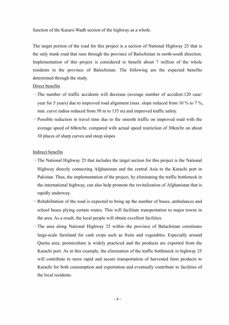
A : There is no noticeable damage and requires no rehabilitation or replacement. If
expansion is necessary, however, the same structure should be added for expansion.

- 17 -
Countermeasure 1
Nothing
specifically
required
Countermeasure 2
Widen without
repairing
Countermeasure 3
Rebuild a part of
the structure
Countermeasure 5
Rebuild entire
structure
Structure
Condition
Category-A
Structure
Condition
Category-B
Structure
Condition
Category-C
Structure
Condition
Category-D
Structure
Condition
Category-E
Widening
required
Widening
required
Widening
required
B : There is some damage but it is not structurally critical at present. In the case of
serious damage in bridge rails, they should be repaired. If expansion is necessary,
however, the same structure should be added for expansion.
C : There is a fair amount of damage but these are not structurally critical at present.
The damage can develop into critical ones depending on the future condition of the
road (e.g., increase in traffic). If the damage is extensive in some parts, the portions
concerned should be repaired or replaced. If expansion is necessary, however, the
same structure should be added for expansion.
D: There is extensive structurally critical damage. The earliest possible repair is
required. Thus the item concerned is to be replaced in this plan.
E : There is extremely extensive and intensive damage that is structurally critical. It
can cause collapse at any time and possibly injure people. Thus, the item
concernedfss requires urgent replacement.
Figure 2.3 presents a flow chart on the basic concept of structure rehabilitation.
Figure 2.3 Flow chart of basic concept on building structure repair
2.2.1.8 Policy for Construction Methods and Periods
(1) Policy concerning construction period
The policy for determining the construction period takes into account the following
points:
- The work shall be started as early as conveniently possible and the schedule will be

- 18 -
formulated on the basis of the nature of the project (road and structures) within the
framework of the grant assistance system.
(2) Policy concerning construction methods
The policy for determining the construction methods takes into account the following
points:
- In consideration of the fact that the section to be constructed under this plan is
included in a trunk road, influence on the current traffic shall be minimized as much
as possible. The site conditions require that the construction work be conducted along
one side of the road and hence the methods shall be determined taking into account
the safe thoroughfare of the current traffic.
- In determining the timing of construction of river crossing structures, particular
attention shall be paid to the fact that rapid flooding of rivers may occur because of
the characteristics of rainfalls in the area.
2.2.2 Basic Plan
2.2.2.1 Selection of Scope of Basic Design Study under Japanese Grant Aid
(1) Outline
In the 5 years medium term plan for investment by NHA, the improvement plan of
Kararo~Wadh (96km) section on National Route 25 has been formulated as a one of the
group of project of improvement for existing roads. PC-I has not been originally
prepared under the conception of the Japanese Grant Aid, but also for the procurement
of local contractors.
As a result of basic design study, the estimated cost of PC-I can not cover the full scale
improvement for 96km including the structure rehabilitation.
Therefore, the discussion between the Study Team and NHA was take place and the two
parties agreed that the scopes of the project under Japanese Grant Aid will be identified
on the basis of determination of Pakistan portion which can be improved by themselves.
(2) Conditions to be considered for the selection of scope
The conditions to be considered for the selection of the project scope are described as
follows:

- 19 -
1)Main points to be considered
Main points to be considered for the selection of scope are shown as follow.
Table 2.7 Summary of Elements to be considered
Expected Effect Current condition of project road Elements to be considered
1 Decrease of traffic accident
Frequent traffic accident Improvement of dangerous curve and steep slope
2 Enhance the function as trunk road & international road
Demand of smooth transportation to domestic and international
Widening of road width to 7.3m for international road standard
3 Benefits to the habitant along the road
Difficulty to access the basic social services (e.g. education)
Improvement of road condition
2)Dividing of the road section to be selected
The project road has been divided for the selection of target section in accordance with
the topographic features and other considerable condition of road (refer to Fig. 2.4).
(3) Evaluation of alternatives for the selection
Table2.8 shows the result of the evaluation of alternatives for the selection.

Fig
ure
2.4
E
xis
tin
g C
on
dit
ion
an
d F
eatu
re o
f th
e P
roje
ct R
oad
Km
0
Exi
sting R
oad W
idth
Hilly
Port
ion
17.3
Km
Hilly
and M
ounta
inous
Port
ion
53.7
Km
Fla
t P
ort
ion
2
5K
m
Pro
file
Pla
n
Km
11
Km
17.5
Km
38.5
Km
48.5
Km
61.3
Km
96
Km
61.3
W=5.0
~6.1
mW
=7.3
m
Kara
ch
Quett
a
Km
0Km
17.3
Km
96
Km
71
Shar
p C
urv
e
Ste
ep C
urv
e( )
( )
Shar
p C
urv
e
Ste
ep C
urv
e
( )
Shar
p C
urv
e
Ste
ep C
urv
e
Critical
Hazar
d Section
Critical Hazar
d S
ection
Critical
Hazar
d Section
- 20 -

Tab
le 2
.8
E
valu
ati
on
of
alt
ern
ati
ves
for
the
sele
ctio
n
Con
ten
t of
im
pro
vem
ent
Len
gth
of
se
lect
ed
sect
ion
Mil
e st
one
Rea
son
of
sele
ctio
n
Des
ign
con
cep
t
Roa
d
Dra
inage
stru
ctu
re
Bri
dge
An
cill
ary
Ap
p. co
st
(bil
lion
PR
)
1
96k
m
0k
m~
96k
m
Ori
gin
al
sect
ion
as
sam
e as
orig
inal
PC
-I
----
----
----
----
- F
ull
sp
ec. --
----
----
----
--1)P
avem
ent
wid
th;
7.3
m
2)s
hou
lder;
3m
(m
in. 1m
) 3
Min
.Ra
diu
s;as
per
des
ign
sp
eed
4)M
ax.g
rad
ien
t;7%
5)S
tru
ctu
re: R
efer
rin
g t
o th
e re
sult
of
con
dit
ion
su
rvey
Carr
iagew
ay
-A
c su
rface:
12cm
-B
ase
cou
rse:
20cm
-S
ubbase
cou
rse:
27cm
S
hou
lder
-S
urf
ace:
DB
ST
-B
ase
cou
rse:
20cm
-Rep
lace
of
RC
pip
e(3
4)
-Wid
enin
g
of
RC
p
ipe
(8)
-R
epla
ce
Box
C
ulv
ert
(251)
-Wid
enin
g
of
B
ox
Cu
lver
t (2
5)
-
Wid
enin
g
of
Sla
b
C(
69)
T
otal:
387 C
ulv
erts
-Rec
onst
ruct
ion
to
P
C g
art
er(
5)
-R
econ
stru
ctio
n
to
RC
gart
er(
6)
-W
iden
ing
of
RC
gart
er(
2)
-W
iden
ing
of
slab
bri
dge(
8)
T
otal:
21 B
rid
ges
-Sid
e d
rain
-R
etain
ing w
all
-T
raff
ic s
ign
-G
uard
rail
-C
ente
r li
ne
mark
ing
-Km
pos
t
6.2
5
2
53
.7k
m
17.3
km
~
71k
m
Excl
usi
on o
f fl
at
terr
ain
se
ctio
n,
bec
au
se
of
on
–goi
ng i
mp
rovem
ent.
In
th
e re
st
of
sect
ion
71k
m,
17.3
km
fr
om
the
start
poi
nt
is e
xcl
ud
ed a
t th
e p
oin
t of
vie
w
of
top
ogra
ph
ic
con
dit
ion
, d
iffi
cult
y
of
the
wor
ks
an
d c
ost
effe
ctiv
enes
s
----
----
----
----
- F
ull
sp
ec. --
----
----
----
--1)P
avem
ent
wid
th;
7.3
m
2)s
hou
lder;
3m
(m
in. 1m
) 3M
in. R
ad
ius;
as
per
des
ign
sp
eed
4)M
ax.g
rad
ien
t;7%
5)S
tru
ctu
re: R
efer
rin
g t
o th
e re
sult
of
con
dit
ion
su
rvey
Carr
iagew
ay
-A
c su
rface:
12cm
-B
ase
cou
rse:
20cm
-S
ubbase
cou
rse:
27cm
S
hou
lder
-S
urf
ace:
DB
ST
-B
ase
cou
rse:
20cm
-Rep
lace
of
RC
pip
e(1
6)
-Wid
enin
g
of
RC
p
ipe
(6)
-R
epla
ce
Box
C
ulv
ert
(135)
-Wid
enin
g
of
B
ox
Cu
lver
t (2
0)
- W
iden
ing
of
Sla
b
C(
43)
T
otal:
220 C
ulv
erts
-Rec
onst
ruct
ion
to
P
C g
art
er(
3)
-R
econ
stru
ctio
n
to
RC
gart
er(
3)
-W
iden
ing
of
RC
gart
er(
2)
-W
iden
ing
of
slab
bri
dge(
5)
T
otal:
13 B
rid
ges
-Sid
e d
rain
-R
etain
ing w
all
-T
raff
ic s
ign
-G
uard
rail
-C
ente
r li
ne
mark
ing
-Km
pos
t
3.5
3
53
.7k
m
17.3
km
~
71k
m
Sam
e as
the
abov
e. B
ut,
re
habil
itati
on
of
stru
ctu
res
are
lim
ited
to
wh
ich
are
aff
ecte
d b
y
reali
gn
men
t of
roa
ds.
----
----
----
----
Lim
ited
Sp
ec. --
----
----
---
1)P
avem
ent
wid
th;
7.3
m
2)s
hou
lder;
3m
(m
in. 1m
) 3M
in. R
ad
ius;
as
per
des
ign
sp
eed
4)M
ax.g
rad
ien
t;7%
5)
Reh
abil
itati
on
of
stru
ctu
res
lim
ited
to
w
hic
h are
aff
ecte
d
by r
eali
gn
men
t of
roa
ds.
Carr
iagew
ay
-A
c su
rface:
12cm
-B
ase
cou
rse:
20cm
-S
ubbas
cou
rse:
27cm
S
hou
lder
-S
urf
ace:
DB
ST
-S
ubbase
cou
rse:
20cm
-Rep
lace
of
RC
pip
e(1)
-Wid
enin
g
of
RC
p
ipe
(2)
-R
epla
ce
Box
C
ulv
ert
(26)
- W
iden
ing o
f S
lab C(
8)
Tot
al:
37 C
ulv
erts
-Rec
onst
ruct
ion
to
R
C g
art
er(
1)
-S
ide
dra
in
-Ret
ain
ing w
all
-T
raff
ic s
ign
-G
uard
rail
-C
ente
r li
ne
mark
ing
-Km
pos
t
2.2
5
4
96k
m
0k
m~
96k
m
Excl
usi
on
from
ro
ad
im
pro
vem
ent
wh
ere
the
pavem
ent
wid
th
is
ass
ure
d
to7.3
m.
Mor
eover
, ex
clu
sion
w
her
e th
e P
ak
ista
n s
ide
can
im
pro
ve
the
por
tion
ex
pec
tin
g t
he
wor
ks
can
be
exec
ute
d
rela
ted
to
p
hysi
cal
con
dit
ion
. T
he
stru
ctu
res
evalu
ate
d
as
D a
re r
ehabil
itate
d.
----
----
----
----
Lim
ited
Sp
ec.-
----
----
----
To
44.8
km
Sec
tion
, 0~
11k
m(1
1k
m)、
17.5
~3
8.5
km
(21
km
),
48.5~
61
.3k
m(1
2.8
km
) 1)P
avem
ent
wid
th;
7.3
m
2)s
hou
lder;
2m
(m
in. 1m
) 3M
in. R
ad
ius;
as
per
des
ign
sp
eed
4)M
ax.g
rad
ien
t;7%
5)
Reh
abil
itati
on
of
stru
ctu
res
lim
ited
to
wh
ich
are
aff
ecte
d b
y
reali
gn
men
t of
ro
ad
s an
d
D
evalu
ate
d s
tru
ctu
re
To
44.8
km
Sec
tion
C
arr
iagew
ay
-A
c su
rface:
12cm
-B
ase
cou
rse:
20cm
-S
ubbase
cou
rse:
27cm
S
hou
lder
-S
urf
ace:
DB
ST
-S
ubbase
cou
rse:
20cm
T
o 51.2
km
Sec
tion
-Sh
ould
er g
rad
ing
-C
ente
rlin
e m
ark
ing
-Rep
lace
of
RC
pip
e(1
6)
-Wid
enin
g
of
RC
p
ipe
(1)
-R
epla
ce
Box
C
ulv
ert
(97)
-Wid
enin
g
of
B
ox
Cu
lver
t (2
) -
Wid
enin
g o
f S
lab C(
9)
Tot
al:
125 C
ulv
erts
Non
e -S
ide
dra
in
-Ret
ain
ing w
all
-T
raff
ic s
ign
-G
uard
rail
-C
ente
r li
ne
mark
ing
-Km
pos
t
2.0
- 21 -

- 22 -
(4) Determination of selected project scope
According to the evaluation of alternatives, alternative-4 is only feasible for the project.
The outline of selected project scope of alternative-4 is shown as follow (refer to Fig.2.5)
and the improvement items are summarized in the following table 2.9.
Figure 2.5 Outline of selected project scope
Table 2.9 Items to be rehabilitated in the project
Item Component Remarks
Requested section 96km 0km~96km
Project objective section 96km 0km~96km
1.Road
1) Major improvement section
* Road Length : 44.8km
* Carriageway
- Width : 7.3m(3.65mx2 lanes)
- Pavement : Surface As Concrete
12cm
Base Course 20cm
Sub-Base Course 27cm
* Shoulder
- Width : 2.0m each side (min. 1m)
- Pavement : DBST
Sub-Base Course :20cm
0km~11km (11km),
17.5m~38.5km (21km),
48.5km~61.3km (12.8km)
① ROAD
② STRUCTURE
km0.0 km11.0 km17.5 km38.5 km48.5 km61.3
Minor
Improvement
Section
Major
Improvement
Section
Existing Road
W=6.2m
L=6.5km
New Road
W=7.3m
L=11.0km
W=7.3m W=6.2m
②-1 : Replacement of Seriously Damaged Existing Structure (Category-D ; Need of immediate rehabilitation)
Major
Improvement
Section
Major
Improvement
Section
Minor
Improvement
Section
Minor
Improvement
Section
New Road
W=7.3m
L=21.0km
New Road
W=7.3m
L=12.8km
Existing Road
W=6.2m
L=10.0km
Existing Road
W=7.3m
L=34.7km
W=7.3m W=7.3mW=6.2m
W=7.3m
②-2 : Replacement/Expantion of Existing Structure at Road Alignment Improvement Section
Minor
Improvement
Section
Major
Improvement
Section
Major
Improvement
Section
Major
Improvement
Section
Minor
Improvement
Section
Minor
Improvement
Section

- 23 -
2) Minor improvement section
* Road Length : 51.2km
* Shoulder grading
* Center line marking
11km~17.5km (6.5km),
38.5km~48.5km (10km)
61.3km~96km (34..7km)
2. Drainage structure
1) Cross drain
2) Longitudinal drain
(In objective section:0km~96km)
* Reconstruction : 113 culverts
* Extension of width : 12 culverts
* Earth ditch : 41,970 m
* Masonry ditch : 5,080 m
* Concrete ditch : 906m
*D categorized culverts: 88
*C categorized culverts: 25
*A categorized culverts: 6
*B: categorized culverts: 6
3. Bridge
* Reconstruction : No bridges to be
reconstructed
* Extension of width :No bridges to be
extended
4. Ancillary
Drainage:Catch basin、Inlet pipe
Retaining Wall : Stone Masonary,
Gabion etc.
Traffic sign :103 Nos.
Guard rail:5,500m
Center line marking:0-96km
Kmpost:97 Nos.
Note : Category of actual culvert condition:
In concluding the above, the basic concept for the rehabilitation of structures (especially
evaluated as category C) is given as follow.
The structures evaluated as category C have some damage, but not in the critical condition
for road user in present. Therefore, these category C structures are excluded from the
project at the point of view of emergency degree except the structures affected by road
realignment section by the project. They should be maintained in manner by the Pakistan
Government with the consideration of traffic increment in future.
Rearding to handling of building structures of soundness evaluation C, the basic
philosophy of the survey team in arriving at the foregoing conclusions is as follows:
The structures along the sections whose soundness evaluation value is equal or inferior to
D and the sections whose alignment after the completion of the plan does not trace
A: Good condition
B: No need of rehabilitation
C: Need of rehabilitation in future
D: Need of immediate rehabilitation

- 24 -
existing roads are to be repaired under this plan. Structures of soundness evaluation C that
are not in urgent need of repair despite some degree of damage will not be repaired.
However, in consideration of the possibility of becoming dangerous due to future changes
in conditions (increase in amount of traffic, etc.), maintenance (repair, etc.) by the
government of Pakistan to prevent actual damage from getting worse is required.
2.2.2.2 Facility Plan for Sections Concerned
(1) Alignment improvement plan
1) Design of sections and design conditions
1-1) Design of sections
Regarding the section of 96km concerned, the sections are designated as “road
amelioration” sections and “road improvement” sections, and their repair work has been
studied, taking into account the analysis of geographic features and conditions of the
existing roads as well as the total construction cost, as follows:
Table 2.10 Improvement work of each design section
Section Length Current
width
Application Work
km 0.0 - 11.0 11.0km 5.0 - 6.2m Major improvement All major work concerning road improvement
km 11.0 - 17.5 6.5km 6.2m Minor improvement Forming of road shoulders, dividing line on road surface,
rehabilitation of D class structures, etc.
km 17.5 - 38.5 21.0km 6.2m Major improvement All major work concerning road improvement
km 38.5 - 48.5 10.0km 6.2m Minor improvement Forming of road shoulder, dividing line on road surface,
rehabilitation of D class structures, etc.
km 48.5 - 61.3 12.8km 6.2m Major improvement All major work concerning road improvement
km 61.3 - 96.0 34.7km 7.3m Minor improvement Forming of road shoulders, dividing line on road surface,
rehabilitation of D class structures, etc.
Remarks: Total length of major improvement sections = 44.8km. Total length of minor improvement
sections = 51.2km.

- 25 -
1-2) Design conditions
The study was conducted based on the design speeds of 100km/h for flat portions, 80km/h
for the hilly portions and 60km/h for mountainous areas, in consideration of the AASHTO
values determined by PC-I subject to the standards of Pakistan according to various
geographic features of the sections covered by the current plan. After determination of the
design sections indicated in the above table, the design speed for the road amelioration
sections was fixed at 60km/h, because such sections are mostly located in mountainous
areas
The design speed for the road improvement sections were studied by taking km 0 – 71.0
as that for hilly areas and km 71.0-96.0 as that for mountainous areas.
Design standards
Standards of Pakistan and the U.S. (AASHTO) were adopted as design standards.
Japanese road standards (Road Construction Ordinance) were also referred to.
Design speeds
Design speeds were fixed respectively for the sections indicated in the table below. For the
junctions of sections having different design speeds, attention was paid in order to avoid
rapid change of alignment.
Table 2.11 Design speed for each design section
Section Design speed Remarks
km 0.0 - 11.0, 17.5 - 38.5, 48.5 - 61.3,
61.3 - 71.0
60km/h Mountainous and hilly area
km 11.0 - 17.5, 38.5 - 48.5 80km/h slight hilly area
km 71.0 - 96.0 100km/h flat area
Horizontal alignment and longitudinal profile
The sections of design speed of 60km under the current plan actually have many curves
whose radius does not satisfy the minimum radius. Curves in some sections meet the
requirements of minimum radius, but they are often not in harmony with the plan, because,
for example, two or more curvatures are hypothesized for a single curve. In this plan, these
conditions were taken into account and studied.
Concerning the longitudinal alignment, there are many sections with a design speed of
60km/h that have slopes with inclines exceeding the maximum incline. Such sections are

- 26 -
mostly located in mountainous areas or in sections before and after some structures. In this
plan, these sections were taken into account and studied, in consideration of the
geographical features of each section, in order to avoid having any slopes with inclines
exceeding the maximum incline mentioned below.
The minimum radius and the maximum incline for each design speed are as follows:
Table 2.12 Minimum radius and maximum incline for each design speed
Section Design speed minimum
radius
maximum
incline
km 0.0 - 11.0, 17.5 - 38.5, 48.5 - 61.3, 61.3
- 71.0
60km/h 135m 7%
km 11.0 - 17.5, 38.5 - 48.5 80km/h 250m 6%
km 71.0 - 96.0 100km/h 435m 5%
Superelevation
The maximum superelevation value is to be 6% with consideration to the safety of large
cars passing through curves. Curves whose radius exceeds R3000 shall not be
superelevated.
Width of roads
For the road amelioration sections, the number of lanes shall be two and the roadway
width shall be 7.3m, in consideration of the design standards, the results of traffic analysis,
the width of adjacent sections, etc.
The width of road shoulders shall be basically 2m, because the road amelioration sections
are mostly located in hilly or mountainous areas. However, in some areas such as hard
rock excavation areas where it is difficult to ensure a 2m width, a width of 1m shall be
ensured at the least. For the road improvement areas, the width of road shoulders shall be
kept as it is and only the road shoulders that need to be repaired, such as those from which
waste water flows onto roadways, shall be reformed by grader.

- 27 -
Typical Cross Section(Fill Section
Typical Cross Section(Cut Section)
Figure 2.6 Basic sectional view of road
Slope protection method
In consideration of the soil conditions at the site, the incline of embankment slope made of
soil with pebbles shall be 1:0.5, and that of embankment slope made of other soils shall be
1:2. The incline of excavation slope made of hard rock shall be 1:0.5, that of excavation
slope made of soft rock shall be 1:0.75 and that of excavation slope made of normal rock
shall be 1:1. As countermeasures against the erosion of embankments by rainwater,
surface soil containing seeds and leaf mold stripped at the time of clearing and eradicating
work shall be put back on the surface of the embankment slope and concrete steps shall be
prepared around sagging parts where rainwater tends to converge. As foot protection of
steep embankment slopes and as a countermeasure against falling stone from the
excavation slopes, retaining walls are to be installed.
Sub Base Material
General Fill
41cm Sub Grade
5cm A.C. Wearing
7cm A.C. Binder20cm Base
27cm Sub Base (if required)
20cm Sub Base Material
Guard Rail
Shoulder
( min.)
4.0%
G.L.
Existing Road Width
Existing Carriageway
Existing Shoulder
Existing Culvert (Ref.)
Carriageway
2.5%2 .5%Guide Post
( min.)
4.0%
Shoulder
DBST
41cm Sub Grade (if required)
1:0.75 Soft Rock
1:1.0 Soil
1:0.5 Hard Rock
( min.)
4.0% 2.5%2.5%
( min.)
4.0%
ShoulderCarriageway
Shoulder
Sub Base Material
20cm Sub Base Material
5cm A.C. Wearing
7cm A.C. Binder
20cm Base
27cm Sub Base (if required)
G.L.
Existing Carriageway
Existing Shoulder
Existing Road Width
DBST

- 28 -
Outline of Design Conditions
The study team and the counterpart personnel of NHA discussed the design conditions,
after the joint field survey by the study team and the counterpart engineers, during the
study in Pakistan in January and February 2005. The study team analyzed and examined
the results and the design details proposed by PC-I, and finalized the design conditions of
the road rehabilitation plan for the target section as presented in the following table. The
following shows the outline of section-wise design conditions that include design speed,
road width, shoulder width, and slope dimensions.
Table 2.13 Outline of Design Condition
Terrain Condition
Description UnitsFlat Rolling
Mountainous
/Hilly
Design Speed Km/hr 100 80 60
No. of Lanes No. 2 2 2
Roadway Width m 13.3 11.3 9.3
Carriageway Width m 7.3 7.3 7.3
Shoulder Width m 3 2 1 Min
Cross Fall on Carriageway % 2 2 2
Cross Fall on Shoulder % 4 4 4
Minimum Radius of Horizontal Curve m 435 250 135
Maximum Gradient % 5 6 7
Maximum Superelevation % 6 6 6
Minimum Sight Distance m 160 110 75
Granular soil Angle 1:1.5 1:1.5 1:1.5 Fill Slope
Other soil Angle 1:2 1:2 1:2
Hard Rock Angle 1:0.5 1:0.5 1:0.5
Decomposed Rock Angle 1:0.75 1:0.75 1:0.75 Cut Slope
Other than Rock Angle 1:1 1:1 1:1
2) Land for road construction
The study team confirmed, in the discussion with NHA in January 2005, that 30 m-wide
strip of land on both sides of the centerline of the existing road had been secured for this
rehabilitation project.

- 29 -
3) Section-wise traffic and standard axle load by vehicle type
The traffic survey conducted at the end of January 2005 revealed that the annual average
daily traffic (AADT) is 4313 vehicles. The figure is composed of the following: small
vehicle: 38.4%, bus: 8.0%, large vehicle including tractors: 31.4%. This figure is also
close to 4428 confirmed by the PC-I survey conducted in August 2003. For axle load for
each vehicle type, typical values (converted to 8.2 ton axle load, ESA) for the vehicle
types were adopted based on the figures in the PC-I and also on the results of some
surveys conducted in Pakistan in the past. The following is the traffic and standard axle
load per vehicle type.
Table 2.14 Section-wise traffic and standard axle load per vehicle type
Traffic Axle load Vehicle Type
Number Ratio (ESA/Vehicle)
1 Motorcycle 954 22.1% -
2 Passenger car, Taxi 903 20.9% -
3 Wagon, Pickup truck 754 17.5% -
4 Bus 346 8.0% 0.504
5 Tractor 74 1.7% 5.680
6 Truck (2 axle) 567 13.1% 4.670
7 Truck (3 axle) 413 9.6% 8.840
8 Trailer (4 axle) 195 4.5% 10.350
9 Trailer (5 axle) 96 2.2% 10.840
10 Trailer (6 axle) 11 0.3% 10.840
11 Other vehicles 0 0.0% -
Total 4313 100%
4) Material and bearing strength of the existing road
CBR tests on the existing road were conducted to grasp the present conditions of
pavement and roadbed and in order to optimize its use. The tests revealed that all the
samples yielded values over CBR 30 required for typical lower roadbed materials and they
were found to be good at least for the lower roadbed. The following is the result of the
tests.

- 30 -
Table 2.15 Test Result on Material and bearing strength of the existing road
Pavement Sub grade
Item Surface (cm)
Base course (cm)
Sub base course (cm)
Total (cm)
Asphalt content
(%)
Bearing strength (CBR)
Average 4.72 15.57 18.35 38.65 3.90 43.46 Standard deviation
1.04 4.26 5.39 - 0.20 6.86
Max. 6.60 24.00 30.00 60.60 4.25 61.70
Min. 2.90 9.00 8.00 19.90 3.38 35.90
(2) Pavement plan
1) Design method
The existing road is paved with either asphalt (DBST) or low-cost asphalt (Bitmac). At the
time of the field survey, one section of the road (km 65 - 93) was being converted from
DBST to Bitmac. In this plan, the pavement structure and thickness were determined
considering the existing conditions, current situation, bearing capacity, traffic, and axle
loads, in order to maximize the use of the existing road. The design is also in line with
AASHTO guidelines and the service life of the pavement was set at 10 years. The
following are the design conditions and pavement specifications.
2) Design conditions
Design pavement service life : 10 years
Design traffic : 4313 vehicles/day/direction
Design axle load : 29.4 million, cumulative standard axle load (ESAL)
Roadbed bearing capacity : 30 or over for existing road, 10 or over for extension
3) Pavement structure and specifications for roadway
Surface course : 12 cm asphalt concrete (5 cm surface + 7 cm base layer)
Base course : 20 cm, size-adjusted crushed aggregate
Sub base course : 27 cm granular material, (procured at site)
4) Specifications of road shoulders
Surface layer : double bituminous surface treatment (DBST)
Roadbed material : 59 cm, granular material (procured at site)

- 31 -
(3) Traffic safety facilities plan
1) Pavement marking
The centerline and sideline designs are prepared for the entire section of the target road. In
addition, 20 zebra zones for schools and villages on the road and 40 warning zones for
existing bridges were also planned. The following shows designs of the typical road
markings.
General Bridge Area Pedestrian Crossing
2) Traffic signs
Traffic signs are planned for the following locations that require such signs.
Table 2.16 Traffic Sign Design Plan
Item Quantity Remarks Speed limit 15Nos. In vicinity of public facilities, at tight corners Curve 22Nos. At curves with small radius Slope 31Nos. At road sections with high longitudinal slope Stop 11Nos. Intersection with minor roads in villages, at the entrance Intersection 11Nos. Intersection with minor roads in villages, at the entrance Pedestrian crossing 13Nos. At schools, villages
Total 103Nos.
3) Safety barriers
The following facilities are planned to ensure safety of traffic at places where they are
required.
Guardrails : For road sections with bridges and both ends of the bridges, for road
sections where over 5m of earth filling is expected, problematic
sections in road alignment (tight corners)
Guard post : At both ends of guardrails
Edge marker : At both ends of Guard post, at other necessary places

- 32 -
(4) Drainage facilities plan
1) Transversal drainage facilities
1-1) Design conditions of drainage facilities
The design conditions follow both “Standardization of bridge superstructures” of Pakistan
(Jan. 2005) that is based on AASHTO and the “specifications for highway bridge
designing (I, II, III, IV, V) of Japan Road Association. The adopted figures are listed in
table 2.17.
Table 2.17 Design Standard for Transversal Drainage Facilities
Item Design Standard Remarks
(design basis)
Active load Pakistani Standard Class-A Bridge design
Standard
Temperature
load
±25oC Bridge design
Standard
Centrifugal
load
None Close to line on plan
Seismic load k=0.1g After Seismic
Zones of Pakistan
Dead load Steal :77kN/m3
(7,850kg/m3)
Reinforced concrete : 24.5 kN/m3
(2,500kg/m3)
Concrete :23.5 kN/m3 (2,400kg/m
3)
Asphalt concrete : 23.5 kN/m3
(2,400kg/m3)
Bridge design
Standard for
concrete and asphalt
concrete
Des
ign l
oad
Asphalt
pavement
50mm Bridge design
Standard
Design strength of
concrete
Culvert :25N/mm²
Bridge superstructure: 25N/mm²
Bridge substructure: 21N/mm²
Additional facilities None Note) Design strength of concrete : 28
th day strength
1-2) Road width plan
The detailed widths of culverts are taken to be the same as those of the road. The roadway
width is 7.3 m and the shoulder width is 2.0 m (12.1m for two lanes) based on the standard
of Pakistan as shown in the following figure.

- 33 -
2,000 2,000 4007,300
12,100
400
1-3) Outline of rehabilitation
The rehabilitation work for drainage facilities (culverts) in this plan is divided into the
following two modes in terms of the extent of rehabilitation: A) replacement, B) expansion.
The replacement work includes intake and outlet facilities construction and expansion
work includes construction of intake and outlet facilities designed in accordance with the
road alignment.
The culvert structures to be rehabilitated for the target road section in this plan are those
judged D for their structural soundness and those require reconstruction to fit the improved
road alignment. The rehabilitation methods for those structures are listed in Table 2.18.
Table 2.18 Mode of Rehabilitation for Target Culverts
Basis for rehabilitation
Judged Soundness Rehabilitation detail Number of target
A Use of existing facilities
6
B Ditto 6
Structures to be reconstructed due to road re-alignment
C Remove the existing, new construction
22
Structures requiring urgent rehabilitation
D Ditto 91
1-4) Rehabilitation of culvert by replacement
- Examination of internal width and height
The culverts to be replaced all have sufficient drainage capacity according to the interview
survey at site (no record of overflowing). Thus, the designing maintains the existing
internal width and height. The mode and magnitude of replacement for the target culverts
are listed in Table 2.19.

- 34 -
Table 2.19 Mode and magnitude of replacement for the target culverts
Span Width Heigth
1 00+690 2 1.5 0.75 8.9 90 D Pipe 2 @ 0.75 x
2 00+995 1 3.8 2.8 10.1 90 C Box 1 @ 4.00 x 3.00
3 02+466 1 1.8 0.9 11.4 90 C Pipe 2 @ 1.52 x
4 07+558 2 10.4 2.2 11.4 85 D Box 2 @ 5.50 x 2.50
5 08+732 1 3 4 13.5 70 D Box 1 @ 3.00 x 4.00
6 10+000 1 2.75 3.6 13.2 70 D Box 1 @ 3.00 x 4.00
7 12+200 1 2 1.65 8.45 90 D Box 1 @ 2.00 x 2.00
8 12+415 1 6.15 4.63 11.5 90 D Box 1 @ 6.50 x 5.00
9 12+608 2 10.9 4.1 9.6 45 D Box 2 @ 5.50 x 4.50
10 13+284 1 1.5 2.3 12.3 90 D Pipe 2 @ 1.52 x
11 14+280 1 1.8 1.1 10.6 80 D Box 1 @ 2.00 x 1.50
12 18+114 1 2.52 2.75 8.8 45 D Box 1 @ 3.00 x 3.00
13 18+211 1 3 3.4 8.25 90 C Box 1 @ 3.00 x 3.50
14 18+780 1 1.78 2.5 12.7 90 D Box 1 @ 2.00 x 2.50
15 18+955 1 3.3 2.4 13.74 60 D Box 1 @ 3.50 x 2.50
16 19+797 1 2.43 3.6 8.8 80 D Box 1 @ 2.50 x 4.00
17 19+997 1 2.65 2.1 10.03 90 D Box 1 @ 3.00 x 2.50
18 20+362 1 1.87 2.4 8.8 90 D Box 1 @ 2.00 x 2.50
19 27+477 1 8 5.3 10 62 C Box 1 @ 8.00 x 5.50
20 27+598 1 2.7 3 9.12 70 C Box 1 @ 3.00 x 3.00
21 29+495 1 6.9 7 7.65 70 C Box 1 @ 7.00 x 7.00
22 30+404 1 7.3 5.2 10.2 C Box 1 @ 8.00 x 5.50
23 31+412 1 4.55 4.6 9.9 90 C Box 1 @ 5.00 x 5.00
24 31+700 1 3 2.3 19.6 70 C Box 1 @ 3.00 x 2.50
25 32+690 1 1.26 2.8 11.85 80 D Pipe 2 @ 1.52 x
26 32+740 2 2x1.0 1 9 90 C Box 2 @ 2.00 x 2.00
27 32+825 1 3.1 2 9 60 D Box 1 @ 3.50 x 2.00
28 32+900 1 3.1 3 13.1 60 D Box 1 @ 3.50 x 3.00
29 37+437 1 4.5 2.5 12 90 D Box 1 @ 4.50 x 2.50
30 38+032 1 2.4 2.1 14.9 90 C Box 1 @ 2.50 x 2.50
31 44+832 2 2x0.9 0.9 10 60 D Pipe 2 @ 1.22 x
32 45+810 1 4.5 3.5 10.9 80 D Box 1 @ 4.50 x 3.50
33 50+690 1 2.5 1.65 10.65 80 C Box 1 @ 2.50 x 2.00
34 52+780 5 24.8 2.8 11.85 50 D Box 5 @ 5.00 x 3.00
35 52+995 1 8 2.0 11.6 37 D Box 1 @ 8.00 x 2.50
36 54+135 1 2.3 1.5 14.2 80 C Pipe 2 @ 1.52 x
37 54+665 1 3.1 1.9 13.5 90 D Box 1 @ 3.50 x 2.00
38 54+931 1 1.9 0.8 12.2 85 D Box 1 @ 2.00 x 1.00
40 55+710 1 3.67 2.4 12.7 65 C Box 1 @ 4.00 x 2.50
41 55+845 1 3.2 2 12.5 65 C Box 1 @ 3.50 x 2.00
42 55+900 1 3.1 1.9 10.9 70 C Box 1 @ 3.50 x 2.00
42 56+089 1 3.45 2 9.9 65 C Box 1 @ 3.50 x 2.00
43 56+341 1 3.1 2.45 13.4 65 C Box 1 @ 3.50 x 2.50
44 56+850 1 3.7 1.4 13.5 80 D Box 1 @ 4.00 x 1.50
45 57+875 1 2.4 2 11.5 70 D Box 1 @ 2.50 x 2.00
46 58+835 1 1.9 1.3 9.6 75 D Pipe 2 @ 1.52 x
47 58+945 1 1.25 1.2 12 80 C Pipe 2 @ 1.22 x
48 59+246 1 1.8 1 12.4 90 D Box 1 @ 2.00 x 1.00
49 59+630 1 1.7 1 11.5 70 D Box 1 @ 2.00 x 1.00
50 61+170 1 5.6 3.6 9.7 55 C Box 1 @ 6.00 x 4.00
51 61+227 1 3.3 3.1 10 85 C Box 1 @ 3.50 x 3.50
No.
Mode and magnitude of rehabilitation
Typen @ B x H
Sta.No.Damaged
LevelSkew
Existing Culvert
No. of
Cell
Total
Length l(m)Heigth (m)
Culvert
Width (m)

- 35 -
Span Width Heigth
52 62+095 1 2 1.5 12.8 90 D Pipe 2 @ 1.52 x
53 64+720 1 3.7 1.45 10.5 45 D Box 1 @ 4.00 x 1.50
54 65+625 1 2.3 2.3 11.8 80 D Box 1 @ 2.50 x 2.50
55 70+665 1 1.4 0.5 10 80 D Box 1 @ 1.50 x 0.50
56 71+186 1 1.8 1.1 11 60 D Box 1 @ 2.00 x 1.50
57 72+545 1 3.4 1 9.8 75 D Box 1 @ 3.50 x 1.00
58 72+605 1 0.75 0.75 9.7 90 D Pipe 2 @ 0.76 x
59 72+815 1 1.3 1 9.2 90 D Pipe 2 @ 1.52 x
60 73+237 1 4 1.1 12.6 85 D Box 1 @ 4.00 x 1.50
61 73+748 1 1.1 1.1 9.7 90 D Box 1 @ 1.50 x 1.50
62 73+825 1 1.1 1.1 9.7 90 D Box 1 @ 1.50 x 1.50
63 74+290 1 1.5 1.1 9.7 90 D Box 1 @ 1.50 x 1.50
64 76+915 1 1.8 0.8 10.1 90 D Box 1 @ 2.00 x 1.00
65 76+955 1 1.8 0.8 11.8 90 D Box 1 @ 2.00 x 1.00
66 77+025 1 1.7 0.7 10 90 D Box 1 @ 2.00 x 1.00
67 77+130 1 1.2 0.4 9.3 90 D Box 1 @ 1.50 x 0.50
68 77+220 1 1.8 1.1 11.5 90 D Box 1 @ 2.00 x 1.50
69 77+337 1 1.8 0.6 9.4 90 D Box 1 @ 2.00 x 1.00
70 77+545 1 1.2 0.6 9.7 90 D Box 1 @ 1.50 x 1.00
71 77+770 1 1.6 0.3 9.7 90 D Box 1 @ 2.00 x 0.50
72 77+908 1 2.1 0.7 11.6 90 D Box 1 @ 2.50 x 1.00
73 78+095 1 2.1 0.65 8.4 90 D Box 1 @ 2.50 x 1.00
74 78+265 1 2.2 0.4 10.7 90 D Box 1 @ 2.50 x 0.50
75 78 + 310 1 2 1 9.7 90 D Box 1 @ 2.00 x 1.00
76 78+472 1 2.2 0.6 9.4 90 D Box 1 @ 2.50 x 1.00
77 78+645 1 2.2 1.2 9.3 90 D Box 1 @ 2.50 x 1.50
78 78+662 1 1.8 1 8.6 90 D Box 1 @ 2.00 x 1.00
79 78+745 1 2.4 1 9.4 90 D Box 1 @ 2.50 x 1.00
80 78+945 1 1.3 0.6 9.7 90 D Pipe 2 @ 0.76 x
81 78+975 1 1 0.5 9.7 90 D Pipe 2 @ 0.61 x
82 79+090 1 1.3 1 9.7 80 D Box 1 @ 1.50 x 1.00
83 79 + 132 1 1.8 0.5 9.9 80 D Box 1 @ 2.00 x 0.50
84 79+200 1 1.5 0.65 9.2 90 D Pipe 2 @ 0.91 x
85 79+260 1 1.5 0.4 10 80 D Box 1 @ 1.50 x 0.50
86 79+740 1 1.3 0.5 9.3 90 D Box 1 @ 1.50 x 0.50
87 79+788 1 1.8 0.8 9.5 80 D Box 1 @ 2.00 x 1.00
88 79+855 1 1.9 0.5 9.5 80 D Box 1 @ 2.00 x 0.50
89 79+900 1 1.9 0.5 9.5 80 D Box 1 @ 2.00 x 0.50
90 79+995 1 2.4 0.6 9.8 90 D Box 1 @ 2.50 x 1.00
91 80+040 1 2 1 9.7 90 D Box 1 @ 2.00 x 1.00
92 80+160 1 1.8 0.8 9.7 90 D Box 1 @ 2.00 x 1.00
93 80+338 1 1.8 0.4 9.7 90 D Box 1 @ 2.00 x 0.50
94 80+400 1 1.3 0.8 9.8 90 D Box 1 @ 1.50 x 1.00
95 80+510 1 1.8 0.6 10 90 D Box 1 @ 2.00 x 1.00
96 80+670 1 1.2 0.5 9.4 90 D Box 1 @ 1.50 x 0.50
97 80+840 1 1.8 0.8 10.4 90 D Box 1 @ 2.00 x 1.00
98 80+967 1 1.2 0.3 9.1 90 D Box 1 @ 1.50 x 0.50
99 81+490 1 1.8 0.6 10 90 D Box 1 @ 2.00 x 1.00
100 81+650 1 1.8 1.1 11.85 90 D Box 1 @ 2.00 x 1.50
101 81+695 1 1.8 0.6 9.4 90 D Box 1 @ 2.00 x 1.00
102 81+760 1 1.6 0.7 11.85 90 D Box 1 @ 2.00 x 1.00
103 81+910 1 1.7 0.4 9.5 90 D Box 1 @ 2.00 x 0.50
104 81+995 1 1.3 0.5 9.7 90 D Box 1 @ 1.50 x 0.50
105 82+055 1 1.6 0.4 9.6 90 D Box 1 @ 2.00 x 0.50
106 82+152 1 1 0.2 9.6 90 D Box 1 @ 1.00 x 0.50
107 82+255 1 1.3 0.2 9.1 90 D Box 1 @ 1.50 x 0.50
108 82+328 1 1 0.3 9.1 90 D Box 1 @ 1.00 x 0.50
109 82+360 1 1.8 0.5 9.4 90 D Box 1 @ 2.00 x 0.50
110 82+420 1 1.8 0.5 8.7 90 D Box 1 @ 2.00 x 0.50
111 82+504 1 1.1 0.3 9.2 80 D Box 1 @ 1.50 x 0.50
112 82+610 1 1.8 0.3 9 90 D Pipe 2 @ 0.61 x
113 83+070 1 0.7 0.3 9.6 80 D Pipe 2 @ 0.46 x
No.
Mode and magnitude of rehabilitation
Typen @ B x H
Sta.No.Damaged
LevelSkew
Existing Culvert
No. of
Cell
Total
Length l(m)Heigth (m)
Culvert
Width (m)

- 36 -
Examination of intake and outlet facilities
In order to secure smooth discharge and to prevent erosion of the riverbeds and side slopes,
intake and outlet facilities are planned at the upstream and downstream sides of the culvert
respectively. The structure of the facilities is determined from the viewpoints of cost,
workability, and durability. The sidewall is covered with stone and mortar, and the
riverbed is protected with concrete. In addition, gabion is placed at the end of the intake
and outlet to prevent riverbed erosion.
1-5) Rehabilitation of culvert by expansion
Examination of structure
The expansion of a culvert aims to add a new piece of culvert to the existing one so that
the combined culvert will satisfy the required width of 12. 3 m (roadway 7.3 m + shoulder
2 x 2 m ). The additional portion of the culvert should have the same structure as the
existing one.
Structure Existing structure → Expanded structure
Top slab Concrete → concrete
Concrete → concrete Side wall
Stone and mortar → stone and mortar
The mode and magnitude of rehabilitation for the culverts to be widened are listed in Table
2.20
Table 2.20 Mode and magnitude of rehabilitation for the culverts to be widned
Span Width Heigth
1 02+766 Box Concrete Mason 1 2.4 3.2 78 B 1 @ 2.40 x 3.202 03+810 Pipe Concrete Concrete 1 2x1.0 1 90 B 2 @ 1.22 x3 19+242 Box Concrete Mason 1 4.5 5.4 80 B 1 @ 4.50 x 5.404 27+710 Box Concrete Mason 1 2.4 2.1 90 B 1 @ 2.40 x 2.105 29+957 Box Concrete Mason 1 2.47 3.7 30 B 1 @ 2.47 x 3.706 30+747 Box Concrete Concrete 1 4.52 3.75 90 A 1 @ 4.52 x 3.757 53+689 Box Concrete Concrete 1 4.6 2.85 90 A 1 @ 4.60 x 2.858 53+720 Box Concrete Mason 1 5.7 2.4 65 A 1 @ 5.70 x 2.409 53+905 Box Concrete Mason 1 2.45 1.9 55 A 1 @ 2.45 x 1.9010 58+700 Box Concrete Mason 1 1.85 2.8 80 A 1 @ 1.85 x 2.8011 59+145 Box Concrete Mason 1 2.4 2.5 90 A 1 @ 2.40 x 2.5012 61+077 Box Concrete Mason 1 3.45 3.5 75 B 1 @ 3.45 x 3.50
No.
of
Cell
.No.Type of
Slab
Type of
Side Wall
Damaged
LevelSkew
Existing Culvert
Type
Mode and manitude of
rehabilitation
n @ B x HSta.No. Width
(m)
Heigth
(m)
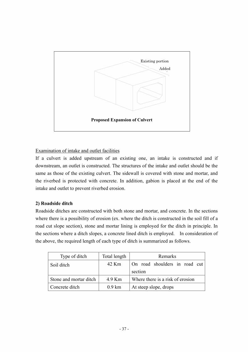
- 37 -
Examination of intake and outlet facilities
If a culvert is added upstream of an existing one, an intake is constructed and if
downstream, an outlet is constructed. The structures of the intake and outlet should be the
same as those of the existing culvert. The sidewall is covered with stone and mortar, and
the riverbed is protected with concrete. In addition, gabion is placed at the end of the
intake and outlet to prevent riverbed erosion.
2) Roadside ditch
Roadside ditches are constructed with both stone and mortar, and concrete. In the sections
where there is a possibility of erosion (ex. where the ditch is constructed in the soil fill of a
road cut slope section), stone and mortar lining is employed for the ditch in principle. In
the sections where a ditch slopes, a concrete lined ditch is employed. In consideration of
the above, the required length of each type of ditch is summarized as follows.
Type of ditch Total length Remarks
Soil ditch 42 Km On road shoulders in road cut
section
Stone and mortar ditch 4.9 Km Where there is a risk of erosion
Concrete ditch 0.9 km At steep slope, drops
拡幅
既設
Proposed Expansion of Culvert
Existing portion
Added ti

- 38 -
2.2.3 Drawings for Basic Design
The drawings prepared based on the design conditions discussed above are presented
below.
List of Drawings
Drawing No. Detail of drawing Number of
sheets
1~49 Road plan and longitudinal profile 49
50 Standard transversal profile of road 1
51~58 Designs of transversal drainage facilities 8
59 Auxiliary road structures 1


