basic design study report on the project · basic design study report on the project for...
TRANSCRIPT

BASIC DESIGN STUDY REPORT
ON
THE PROJECT
FOR
REHABILITATION OF GATES
OF TAUNSA BARRAGE
IN
ISLAMIC REPUBLIC OF PAKISTAN
DECEMBER 2004
JAPAN INTERNATIONAL COOPERATION AGENCY
SANYU CONSULTANTS INC. YACHIYO ENGINEERING CO.,LTD
No.
GM JR
04-238


PERSPECTIVE
THE PROJECT FOR REHABILITATION OF
GATES OF TAUNSA BARRAGE IN ISLAMIC
REPUBLIC OF PAKISTAN
Inta
ke a
t rig
ht b
ank
Wei
r Gat
e
Dow
nstr
eam
Ups
trea
m
Und
er
Slui
cega
teat
Lef
t ban
k
Inta
ke a
t lef
t ban
k
Und
er S
luic
e ga
te a
tRi
ght b
ank

i
Summary
Economy of Islamic Republic of Pakistan (Population 149,030 thousand, GNP 470 USD per Capita,
in 2003) has been largely dependent on the agricultural sector with such dominant indexes of about 1/4 of
GDP, about 1/2 of working population, etc. However, the agriculture sector is now in a very difficult and
sensitive situation being subjected to problematic weather conditions affecting the area. The GDP of the
country in 2000/01 came down due to severe drought that occurred in the country. Situation changed in
2003/2004 because the country’s GDP was 6.4 percent higher than the government objective figures of 5.3
percent due mainly to the favorable conditions of the manufacturing sector, as well as the recovery of the
agricultural sector.
However, economy of the country is still on the decline due to problems of debt repayment, and
other medium and long-term problems such as delay of adequate privatization, stagnation of agricultural
productivity, sluggish growth of export industry, etc. Major problems in the fields of irrigation and
drainage are summarized in the issues of: a) shortage of water resources in accordance with population
increase, b) lowering of irrigation efficiencies caused by the deterioration of provided irrigation systems, c)
facility damages due to water-logging and salt, water contamination, lowering of ground-water table, flood,
and; d) shortages of operation and maintenance (O&M) costs due to low recovery of water-charges, etc.
Of the agricultural infrastructures in the country, Irrigation systems play major role in the
development of the agricultural economy. However, the irrigation systems in the country have been
constructed more than 50 to 100 years ago. Due to its age, the irrigation systems now require large-scale
rehabilitation and improvement. The Punjab Government conducted a survey in 1997/98 and results of
survey revealed that six (6) out of 14 major barrages should urgently be rehabilitated. Especially, the
Taunsa Barrage, that has been constructed more than 46 years ago, is considered to be severely
deteriorated and was considered as top priority for rehabilitation among other barrages.
Also, based on the “Feasibility Study on Taunsa Barrage Irrigation Systems Rehabilitation”,
undertaken by the JICA Study Team in the same period of 1997/98 stated that the Taunsa Barrage should
be urgently rehabilitated as its facilities are very deteriorated.
Details of the problems of the Taunsa Barrage are summarized below confirming the need for the
urgent rehabilitation works of the related facilities;
1) Remarkable lessening function of gates operation due to deterioration of gate facilities, resulting in
inadequate gate operation at flooding period and for diversion of irrigation water. Decrease in the
function of gates can bring about ineffective gate operation for flood discharge, and the possibility
of the Barrage to collapse in the future.
2) Occurrence of remarkable water leakage from gate structure due to lessening function of
water-tightness of the gates.

ii
3) Progress of the damages of apron and riprap structures due to lowering of the river-bed
immediately downstream of the Barrage.
4) Shortages of irrigation water for DG Khan area due to development of sediment materials in the
DG Khan Irrigation Canal at the right bank of the river, which is possibly caused by the shifting of
water-route of the Indus River
The Pakistan Government has considered as most urgent 1), 2) and 4) out of the above mentioned
problems and considered these as priority for improvement and requested to the Japanese Government the
following works/equipment to be undertaken under the Japan Grant-Aid Program in July 2002, aiming at
functional recovery of the Taunsa Barrage and improvement of future operation and maintenance
activities.
a) Rehabilitation of 24 weir gates and replacement of 7 under sluice gates b) Rehabilitation of 60 gate opening and closing devices (hoists) and electrification of 31 gates c) Rehabilitation of 60 gate continual decks of superstructures d) Procurement of 6 bulkhead gates*1 using for coffering dam e) Provision of one set of bulkhead gate stockyard and jetty for the gates f) Procurement of construction equipment (one set of 80 ton and 30 ton cranes, 2 tugboats, 3
working boats, etc.) and spare-parts.
In response to the request made by the Pakistan Government, the Government of Japan dispatched
the Preliminary Survey Team to Pakistan through the Japan International Cooperation Agency (JICA)
during the periods of August to September 2003 and January 2004, to evaluate the urgency and adequacy
of the request, and as a result decided to undertake the Basic Design of the Project under the Grant-Aid
Program. JICA, furthermore, dispatched the Basic Design Study Team to Pakistan from May to July
2004, and conducted a series of discussion with the Pakistan Government agencies concerned and
confirmation of the request contents. The Team conducted the survey on the current conditions of the
Taunsa Barrage and irrigation areas covered by the Barrage, and also operation and maintenance
organization, etc. As the results, gate facilities of the Taunsa Barrage were identified to be in serious
conditions with lessening function due to the deteriorations of the facilities, hard to operate gates
adequately under flooding period and also hard to supply stable irrigation water to the areas. Under the
situations, it was proven that an urgent rehabilitation of the related Taunsa Barrage facilities is needed.
Following these survey results, JICA dispatched the Draft Basic Design Explanation Team to Pakistan in
September 2004 to discuss and confirm the basic design contents of the Project.
The Punjab Provincial Government, therefore, has the plan to provide and rehabilitate related
facilities of the Taunsa Barrage, that includes the following: a) rehabilitation of gate leafs, b) rehabilitation
of apron and riprap structures of the Barrage, c) rehabilitation of under sluice structure at the right bank, d)
construction of new subsidiary weir at the immediate downstream of the Barrage, e) construction and
*1 Floating type gates for the use of temporary coffering dam with water-tightness structures, and towed into
the position by boats, and plunged/emerged by the operation of pumping and drainage devices.

iii
rehabilitation of spur dikes at the upstream portion of the Barrage, etc. in the �Punjab Barrages
Rehabilitation and Modernization Project�.
As to the remaining rehabilitation works excluded from the Japan Grant-Aid program, the
Government of Punjab now discussing with the World Bank and requesting financial assistance for the
required loan to be needed.
In the Basic Design of the Project, the following basic rehabilitation plan has been formulated after
due considerations of restoring of original form, functional recovery, improvement of operation and
maintenance systems of the Taunsa Barrage, etc.
a) On the basis of study results made by the JICA Preliminary Survey Team and data of gate
rehabilitation records conducted by the Punjab Provincial Government during past 5 years,
regarding 22 weir gates, which were evaluated with high priority from view points of
rehabilitation urgency, i) improvement of wheel portions, ii) partial improvement of vertical end
girders and sill beams, and iii) heightening of gate height of one feet (0.31 m) would be
undertaken.
Furthermore, regarding 7 under sluice gates provided at the left bank, i) replacement of whole
gate leafs, ii) improvement of sill beams, and iii) raising of gate height of one feet (0.31m) would
be implemented. The purposes of raising intake water level of one feet height are to secure
stable water supply to the DG Khan Irrigation Canals to restore original conditions, because the
current DG Khan canal capacity was decreased by about 78 percent of the designed capacity due
to severe deposit of diverted sediment materials in the canals. The raising gate crest of one foot
was planned for 29 gates inclusive of weir gates and under sluice gates under the Grant-Aid
Program. The implementation however of the other gates to cope with the raising water level
would be undertaken by the Pakistan Government.
b) Regarding the improvement of gate hoists and rehabilitation of continual decks of superstructures,
gate hoists for 7 under sluice gates and 22 weir gates would be improved with electrification to
cope with a prompt response to meet river flooding speed.
c) In order to expect future improvement of an effective operation and maintenance works of the
Barrage, 65 continual decks of superstructures will be improved from wooden-made decks to metal
decks by grating structure, and 29 opening and closing devices were planned to be shifted to these
decks considering their operability and easy operation and maintenance works.
d) Necessary bulkhead gate numbers were planned to be 5 gates, based upon the study results of the
most optimal and economical number of gates considering the relationships between introduced
numbers of gates and required construction periods, and also required numbers to carry out an
adequate operation and as well as maintenance works of the Taunsa Barrage after implementation
of the Project.
iv
e) Provision of one set of bulkhead gate stockyard and jetty for the gates
f) Procurement of necessary construction equipment (1 unit of 50 ton crane, 2 units of tugboats, and 3
units of working boats) and their spare-parts.
Present maintenance and repair periods for gate leafs and Barrages are limited to only 20 days in
January (considered as �Annual Closure Period�), witch would take place under no river flow conditions in
the Indus River around the vicinity of the Barrage owing to coffering by the Chashma Barrage at the
upstream. Under these conditions, it would be difficult to undertake a full-scale rehabilitation works of the
Barrage within the limited period of time, so that the bulkhead gate systems to close the Barrages at an
immediate upstream were proposed in the Project, in order to realize the implementation of necessary
maintenance and rehabilitation works. These bulkhead gates would be used not only for the gate
rehabilitation works in this Project, but also for similar rehabilitation works at other barrages in the Punjab
Province. The scale and contents of the proposed facilities and equipment proposed by the Basic Design
Study Team are summarized below.
Scale and Contents of Proposed Facilities and Equipment Items Project Scale and Contents
1. Replacement of Left Bank Under Sluice Gate
Type : Single gate type (steel plate guider structure) Scale : Clear span 60 ft x gate leaf height 23 ft x 7 gates (not including
4 under sluice gates at right bank) Replaced Parts : Gate leaf and water-tightness structure, and sill beams (for 7
gates) Improved Parts : Side flame and roller parts
2. Improvement of Related Facilities of Weir Gate
Type : Single gate type (steel plate guider structure) Scale : Clear span 60 ft x gate leaf height 20 ft x 22 gates (total gate
numbers: 53 gates) Replaced Parts : Gate leaf and water-tightness structure, and sill beams (for 22
gates) Improved Parts : Raising sill structure, gate leaf vertical end girder, wheel
portions, and water-tightness (22 gates) 3. Replacement and
Improvement of Gate Hoists
Type : One motor, two drums, electric wire rope winch type Operation Method : Operated from motor side only (Local Control) Number : Under sluice gate : 7 units (7 gates), and weir gate: 22 units (22
gates) Head : Under sluice gate: 32 ft (9.75 m) and weir gate : 29 ft (8.84
m) 4. Electrification of Gate
Hoists Motor Type : Totally enclosed fan-cooled outdoor motor Motor : Under sluice gate : 2.2 kw 6 P continuous rating,
Weir gate : 1.5 kw 6 P continuous rating Power Source : 3 phase AC 50 Hz 400 V Number : 29 units (under sluice gate: 7 units, and weir gate: 22 units)
5. Rehabilitation of Continual Decks of Superstructures
Type : Grating type Scale : Total length 4,342 ft x width 10 ft, total number : 65 gates
6. Procurement of Bulkhead Gates for Temporary Coffering Dam
Type : Steel floating gate Scale : Clear span 60 ft x gate leaf height 25.26 ft x 5 gates Diversion to Others : Possible to divert to other barrages
7. Provision of Bulkhead Gated Stockyard and Its Jetty
Scale : 14,400 m2 (length 150 m x width 90 m) Incline Facility : Rail length 427 ft slope 1/10, winch motor output 5.5 kw x
speed 1.0 m/sec Jetty : Dry masonry revetment
8. Procurement of required Construction Equipment
Truck crane : 50 ton class truck crane Tugboats : Horse power 150 ps x 2 boats Working Boats : Length 8.5 m x width 2.3 m x height 0.8 m x 73 ps x 3 boats
9. Procurement of required Spare-parts for Construction Equipment
Spar-parts required for 3 years of construction periods
v
The proposed Project implementation period is 50.0 month, with 5.5 month for detailed design and
44.5 months for manufacturing /procurement and rehabilitation. The preliminary project costs were
estimated at 5,469 million Japanese Yen (Japanese Yen portion of 5,281 million Yen and Pakistan portion
of 188 million Yen).
With the implementation of the Project, the following project benefits could be expected.
a) Direct Benefits
Reservation of Stable Irrigation Water
The rehabilitation works for the Taunsa Barrage that will be implemented under the Japan
Grant-Aid Program for 29 gates, and the gate leaf raising works with one feet height that will be
implemented by the Pakistan Government for the remaining gates is expected to bring back the original
amounts of diverted irrigation water in the Taunsa Irrigation System. This will therefore make
possible the supply of stable irrigation water to the areas.
- DG Khan Irrigation Canal diverted from the Taunsa Barrage at the right bank of the Indus River is
taking irrigation water of reduced amounts of 9,047 ft3/sec (256 m3/sec) due to the sediment
materials in the Canal. However theses amounts will be increased to 11,564 ft3/sec (327 m3/sec)
*2 after the implementation of the project.
- Canal capacity of Muzaffargah Irrigation Canal diverted from the Taunsa Barrage at the left bank
is expected increase to 8,300 ft3/sec (235 m3/sec)*2. The present capacity is only 7,476 ft3/sec
(2,125 m3/sec).
Improvement of Gate Operation Speed by Gate Electrification and Reduction of Flood Damages
Required gate operation speed to meet flowing down of flood discharges safely would be
secured by the electrification of the gate hoisting devices. Gate operation speed at the conditions of
present and after project implementation could be assessed as shown below, based on the past
maximum flood discharges that occurred in September 14, 1992.
- Required gate operation speed could be calculated at 0.16 m/minute for the initial stage of
flooding and 0.27 m/minute for the final stage of flooding.
- Present gate operation speed made by manual operation is 0.05 m/minute for gate rising case, and
0.10 m/minute for gate lowering case, and these speeds could not respond to the flood occurring
speed.
- Gate operation speed after the project implementation would be 0.30 m/minute for both gate rising
and lowering cases, and these speeds can respond to the flood occurring speed.
*2 The canal capacity of 11,564 ft3/sec and 8,300 ft3/sec indicate the water right at the sites.

vi
Safety Improvement with Well-Maintenance of Barrage
After the implementation of the Taunsa Barrage the safety of the facilities is assured as the
introduction of bulkheads will enable that periodical operation and maintenance works will be done at
the most efficient and appropriate period of time. The present gate maintenance and rehabilitation
works is being done within the limited period of 20 days in January, (during the “Annual Closer
Period”). Under these conditions, it would be difficult to do full-scale rehabilitation works of the
Barrage within the very limited period of time.
b) Indirect Benefits
Usages of Bulkhead Gates at Other Rehabilitation Works of Barrages
Bulkhead gates introduced in the Project can also be used for the rehabilitation works of other
barrages such as Jinnah and Trimmu Barrages contributing to the reduction of required working period
and costs.
Holding of Social Lifeline Functions
The Taunsa Barrage is presently equipped with other important function beside the irrigation
purpose, that is, functions of road bridge, railway bridge, oil and gas-pipelines, electricity and
communication lines, etc. The presence of security measures/facilities of the Taunsa Barrage will
bring about a sense of peace and security to the people working/involved in the O&M of the facility.
These may bring about more time for social life activities and functions due to the assurance that the
facility is safe.
Future management and operation and maintenance (O&M) works of the project facilities are
planned to be undertaken continuously by the Taunsa Barrage Division (TBD) under Irrigation and
Power Department, the Government of Punjab, which has a enough experiences and actual
performances on the management and O&M works of the Taunsa Barrage for the past 50 years. In the
Project new facilities and equipment will be provided namely 5 bulkhead gates, incline facilities for
usages of bulkhead gates, tugboats, cranes, etc. The required staff to maintain these facilities and
equipment could taken/tapped from the present number of the TBD staff with minor changes in the
working positions of staff and/or introduction of on-the-job-training (OJT) systems.
Required O&M costs after project implementation will slightly increased as compared to the
present because of the introduction of bulkhead gates and other equipment. The incremental rates are
estimated at 2 percent of the mean annual O&M costs of the TBD Office for past 10 years.
From the environmental view point, it was assessed that the implementation of the project will
not have any negative impacts around the vicinity of the project area. The Environmental
Conservation Division in the Punjab Provincial Government approved the implementation of the
project in September 6, 2004 based on the provisions of the environmental impact assessment (EIA)
and other necessary environmental procedures adopted in Pakistan.

vii
Based on the series of presentations mentioned above, the project is found to be viable and
recommended for possible Japan Grant-Aid Program project. Finally, it is also recommended that
“Punjab Barrages Rehabilitation and Modernization Project” proposed by the Government of Pakistan
with possible financial assistance from the World Bank be also implemented to effectively support and
complement this Project proposed under Japan Grant Aid Programme. The implementation of the two
projects (under Japan Grant Aid Programme and Under the World Bank Loan programme) will bring
about smooth and effective operations as well as security of Taunsa Barrage Irrigation Facility. This
will also bring about improvement of the social and economic condition and well being of the farmers
and other residents of the Project area and its surrounding areas.

TABLE OF CONTENTS Preface Letter of Transmittal Location Map Perspective Summary Table of Contents List of Figures and Tables Abbreviations
Page Chapter 1 Background of the Project
1-1 Background and Outline of the Project·················································································1-1 1-2 Main Components Requested·······························································································1-2
Chapter 2 Contents of the Project ························································································2-1
2-1 Basic Concept of the Project·································································································2-1 2-1-1 Overall Goal and Project Purpose ···············································································2-1 2-1-2 Outline of the Project ··································································································2-2
2-2 Basic Design of the Requested Japanese Assistance ·····························································2-4 2-2-1 Design Policy···············································································································2-4 2-2-1-1 Basic Policy ································································································2-4 2-2-1-2 Natural Conditions ······················································································2-5 2-2-1-3 Soil Mechanical and Geological Condition ·················································2-6 2-2-1-4 Rehabilitation of Under Sluice Gate and Weir Gate·····································2-7 2-2-1-5 Bulkhead Gates ·························································································2-27 2-2-1-6 Bulkhead Gate Stockyard ··········································································2-38 2-2-1-7 Electrical Facilities····················································································2-40 2-2-1-8 Conditions of Construction and Equipment···············································2-42 2-2-1-9 Procurement and Fabrication of Gate Facilities ·········································2-43 2-2-1-10 Procurement of Other Material and Equipment ·········································2-47 2-2-1-11 Construction Plan and Method ··································································2-49 2-2-1-12 Temporary Works······················································································2-52 2-2-1-13 Operation and Maintenance of Facilities ···················································2-57 2-2-1-14 Ability on Operation and Maintenance of Executing Agency ····················2-58 2-2-1-15 Environmental and Social Considerations ·················································2-58 2-2-2 Basic Plan··················································································································2-59 2-2-2-1 Rehabilitation of Under Sluice Gates and Weir Gates································2-59 2-2-2-2 Gate Hoist ·································································································2-63 2-2-2-3 Electrification of Gate Hoist······································································2-64 2-2-2-4 Rehabilitation of Upper Deck (Superstructure) ·········································2-65 2-2-2-5 Bulkhead Gates ·························································································2-69 2-2-2-6 Tug Boats, Boats, Crane, Spare parts·························································2-71 2-2-2-7 Bulkhead Gate Stockyard ··········································································2-71 2-2-2-8 Electric Facilities·······················································································2-80 2-2-2-9 Temporary Facilities··················································································2-84 2-2-2-10 Specifications and Quantities of Incidental Facilities and Equipment········2-85

2-2-2-11 Scope of the Project ··················································································2-86 2-2-3 Basic Design Drawings······························································································2-87 2-2-4 Implementation Plan ································································································2-102 2-2-4-1 Implementation/Procurement ································································2-102 2-2-4-2 Conditions of Implementation/Procurement ············································2-104 2-2-4-3 Undertaking in Implementation and Procurement ···································2-104 2-2-4-4 Implementation/Procurement and Consultant Supervision ······················2-106 2-2-4-5 Quality Control Management ··································································2-109 2-2-4-6 Procurement Plan ····················································································2-109 2-2-4-7 Implementation Schedule ········································································2-111
2-3 Obligations of Recipient Country ·····················································································2-113 2-3-1 General Obligations ································································································2-113 2-3-2 Obligations Prior to and during the Implementation of the Project··························2-113
2-4 Project Operation Plan······································································································2-114 2-4-1 Organization of Executing Agency··········································································2-114 2-4-2 Components of Operation and Maintenance····························································2-116
2-5 Project Cost······················································································································2-118 2-5-1 Project Cost·············································································································2-118 2-5-2 Operation and Maintenance Cost ············································································2-119 Chapter 3. Project Evaluation and Recommendations········································· 3-1
3-1 Project Effect························································································································3-1 3-1-1 Direct Effect················································································································3-1 3-1-2 Indirect Effect ··············································································································3-3
3-2 Recommendations ················································································································3-3 [Appendices]
1. Member List of the Study Team 2. Study Schedule 3. List of Parties Concerned in the Government of Pakistan 4. Minutes of Discussions 5. List of Data collected 6. Other Relevant Data and Information

Lists of Figures and Tables
List of Figures
Page
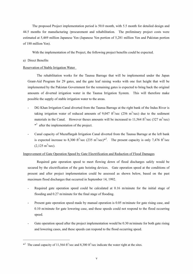
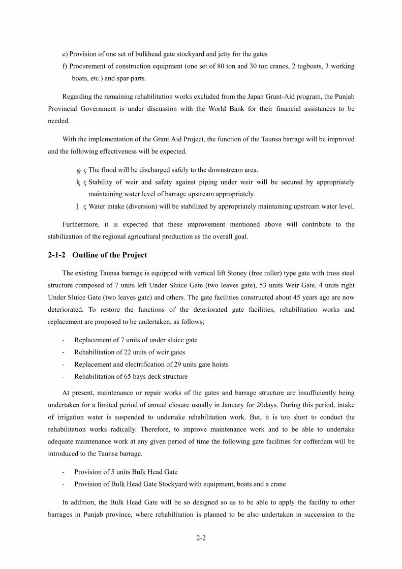
Figure 2-2-1.1 Water level between up and downstream,and discharge
at upstream of Taunsa Barrage ........................................................................... 2-5
Figure 2-2-1.2 Mechanisms Causing Problems with Under Sluice Gates and Weir Gates...................2-15
Figure 2-2-1.3 Subject Parts for Rehabilitation ....................................................................................2-18
Figure 2-2-1.4 Comparison of Roller Structures ..................................................................................2-18
Figure 2-2-1.5 State of Side Girder Deformation .................................................................................2-18
Figure 2-2-1.6 Comparison of Subject Gates for Rehabilitation ..........................................................2-20
Figure 2-2-1.7 Classification Results of the Repair Contents in the Last Five Years ...........................2-21
Figure 2-2-1.8 Relation between Bulkhead Gate Numbers and NPV ..................................................2-34
Figure 2-2-1.9 Gate Rehabilitation Work Schedule with 5 units of Bulkhead Gates ...........................2-35
Figure 2-2-2.1 Remodelling of Locker Assembly ................................................................................2-59
Figure 2-2-2.2 Configuration of Hoist..................................................................................................2-64
Figure 2-2-2.3 Reinforcing Sections for Superstructure.......................................................................2-68
Figure 2-2-2.4 Installation Plan for Other Barrages .............................................................................2-70
Figure 2-2-2.5 Layout of Bulkhead Gate Stockyard.............................................................................2-72
Figure 2-2-2.6 Power Supply Diagram for Gate Control Panel ...........................................................2-82
Figure 2-2-2.7 Electrical Equipment Layout ........................................................................................2-83
Figure 2-2-4.1 General Power Supply Diagram................................................................................. 2-105
Figure 2-2-4.2 Implementation Schedule ........................................................................................... 2-112
Figure 2-4.1 Organization Chart of IPD (2003/04) .......................................................................... 2-114
Figure 2-4.2 Organization Chart of TBD.......................................................................................... 2-114

List of Tables
Table 1-2.1 Main Components Requested .........................................................................................1-2
Table 2-2-1.1 Under Sluice Gates Rehabilitation Methods ............................................................... 2-11
Table 2-2-1.2 Causes of Problems and Remedial Measures ...............................................................2-16
Table 2-2-1.3 Comparison of Roller Unit Structure .......................................................................... 2-17
Table 2-2-1.4 Comparison of Heightening Method of Weir Gate.......................................................2-22
Table 2-2-1.5 Objective Floods for Simulation of Gate Operation ...................................................2-23
Table 2-2-1.6 Simulation for gate Operation ......................................................................................2-25
Table 2-2-1.7 Calculation Results of Gear Strength ..........................................................................2-27
Table 2-2-1.8 Barrages in Punjab........................................................................................................2-28
Table 2-2-1.9 Structural Dimensions of Two Barrages .......................................................................2-28
Table 2-2-1.10 Comparison Table of Temporary Cofferdam Methods to be Selected..........................2-29
Table 2-2-1.11 Comparison of Bulkhead Gate Types .........................................................................2-32
Table 2-2-1.12 Comparison Study on Bulkhead Gate Numbers and Required Rehabilitation Periods 2-33
Table 2-2-1.13 Comparison of NPV .....................................................................................................2-33
Table 2-2-1.14 Combination of the Bulkhead Gates using for Under Sluice and Weir Gates ..............2-36
Table 2-2-1.15 Cost Reduction Coefficient with Production Number of Gate .....................................2-36
Table 2-2-1.16 Production Cost of Bulkhead Gate of Each Alternatives..............................................2-37
Table 2-2-1.17 Candidates of Procurement on Gate Facilities..............................................................2-44
Table 2-2-1.18 Estimated Weight of Steel Product ...............................................................................2-44
Table 2-2-1.19 Comparison of Amount of Procurement for Bulkhead Gates .......................................2-45
Table 2-2-1.20 Comparison of Amount of Procurement for Gates .......................................................2-46
Table 2-2-1.21 Comparison of Construction Method
for Installation and Demolition of Under Sluice Gate ..................................2-51
Table 2-2-1.22 List of Telemeter to be Relocated .................................................................................2-52
Table 2-2-1.23 The Actual River Discharge in Each Case....................................................................2-53
Table 2-2-2.1 List of Materials to be used (Under Sluice Gates)........................................................2-60
Table 2-2-2.2 List of Stresses for Main Members of Under Sluice Gate ............................................2-61
Table 2-2-2.3 Under Sluice Gate Specifications .................................................................................2-61
Table 2-2-2.4 List of Materials to be used (Weir Gates) ..................................................................... 2-62
Table 2-2-2.5 List of Stresses for Main Members of Weir Gate .........................................................2-63
Table 2-2-2.6 Weir Gate Specifications ..............................................................................................2-63

Table 2-2-2.7 Operating Load of Under Sluice Gate ..........................................................................2-64
Table 2-2-2.8 Hoist Specifications......................................................................................................2-65
Table 2-2-2.9 Bulkhead Gate Specifications.......................................................................................2-69
Table 2-2-2.10 Stresses for Main Members of Bulkhead Gate .............................................................2-69
Table 2-2-2.11 Specifications for Auxiliary Equipment for Bulkhead Gate Operation ........................2-71
Table 2-2-2.12 Study Results on Inclination Slope of Inclination Facility
for Bulkhead Gate Stockyard ................................................................2-75
Table 2-2-2.13 Examination of Gate Lifting-up Speed of Inclination Facilities
for Bulkhead Gate Stockyard ................................................................2-77
Table 2-2-2.14 Examination Table on Electric Source for Winch for Stockyard of Bulkhead .............2-79
Table 2-2-2.15 Specifications of Main Electrical Equipment ...............................................................2-81
Table 2-2-2.16 Specifications of Bulkhead Gate Equipment ................................................................2-85
Table 2-2-2.17 Bulkhead Gate Spare Parts ...........................................................................................2-86
Table 2-2-2.18 Scope of the Grant Aid Project .....................................................................................2-86
Table 2-2-4.1 Scope of Work for Technicians to be Dispatched ....................................................... 2-103
Table 2-2-4.2 Residential Specialists Engineers Assignment Plan ................................................... 2-106
Table 2-2-4. 3 Detail Design Staff Plan ............................................................................................. 2-107
Table 2-2-4. 4 Construction Supervision Works for the Gate ............................................................ 2-108
Table 2-2-4. 5 Staffs for Construction Supervision............................................................................ 2-108
Table 2-2-4.6 Staffs for Supervision of Equipment Procurement ..................................................... 2-108
Table 2-2-4. 7 Quality Control Plan (Construction)...........................................................................2-109
Table 2-2-4. 8 Quality Control Plan (Fabrication) ............................................................................. 2-109
Table 2-2-4. 9 Schedule of Gates Repair Works ................................................................................ 2-111
Table 2-4.1 Components of O&M Works of the Equipment ......................................................... 2-117
Table 2-5-2.1 Annual Gate Operation Records................................................................................. 2-119
Table 2-5-2.2 Inspection and Maintenance Costs ............................................................................. 2-120
Table 2-5-2.3 O&M Budgets and Required Expenditures
for Taunsa Barrage and Related Facilities............................................. 2-121
Table 3-1. 1 Restoration of Intake Volume of Irrigation Water (D.G.Khan Irrigation Canal) .............3-1
Table 3-1. 2 Restoration of Intake Volume of Irrigation Water (Muzaffargah Irrigation Canal) ........3-2
Table 3-1. 3 Comparison of Gate Operation Hours for the Largest Flood
(September 14, 1992) between Present and with Project ..........................3-2

Abbreviations Abbreviations ADB Asian Development Bank ASTM American Society for Testing and Materials AWS American Welding Society BHG Bulkhead Gate CTBT Comprehensive Test Ban Treaty DAU Data Acquisition Unit D.G.Khan Dera Ghazi Khan D/S Downstream ECNEC Executive Committee of National Economic Council EIA Environment Impact Assessment EPA Environment Protection Agency F-PRSP Full-Poverty Reduction Strategy Paper GDP Gross Domestic Product GOP Government of the Punjab GPS Gate Positioning Sensor IEE Initial Environment Examination IPD Irrigation and Power Department I-PRSP Interim-Poverty Reduction Strategy Paper IRSA Indus River System Authority ISO International Organization for Standardization JICA Japan International Cooperation Agency MOAF Ministry of Agriculture, Forestry and Fisheries of Japan NPV Net Present Value NWFP North West Frontier Province TBD Taunsa Barrage Division T.P.Limk Canal Taunsa-Panjinad Link Canal U/S Upstream WAA Water Apportionment Accord WAPDA Water and Power Development Authority WB World Bank Glossary Annual Closure The period for around 20 days in January every year in which water diversion
to canals from barrage is suspended. Kharif Summer cropping season from April 15th to October 15th Rabi Winter cropping season from October 16th to April 14th
Currency Rs Pakistan Rupee(s) Yen or J¥ Japanese Yen USD or US$ US Dollar

Exchange Rate(August 2004) Rs = ¥ 1.90 US$ = ¥109.51
Units mm millimeter cusec cubic feet per second cm centimeter MCM million cubic meter m meter MAF million acre feet km kilometer kg kilogram ft feet t (ton) ton sq.m (m2) square meter A ampere sq.km (km2) square kilometer V voltage acre acre KW Kilowatt ha hectare MW Megawatt m/s (m/s) meter per second KVA Kilovolt ampere m3/s (m3/sec) cubic meter per second N Newton cu.m (m3) cubic meter KN Kilo-Newton min minute M/M Man-month hr hour RD Reduced distance ft3/sec (CS) cubic feet per second RL Relative level

Chapter 1 Background of the Project

1-1
Chapter 1 Background of the Project 1-1 Background and Outline of the Project
Economy of Islamic Republic of Pakistan (Population 149,030 thousand, GNP 470 USD per Capita,
in 2003) has been largely dependent on the agricultural sector with such dominant indexes of about 1/4 of
GDP, about 1/2 of working population, etc. However, the agriculture sector is now in a very difficult and
sensitive situation being subjected to problematic weather conditions affecting the area. The GDP of the
country in 2000/01 came down due to severe drought that occurred in the country. Situation changed in
2003/2004 because the country’s GDP was 6.4 percent higher than the government objective figures of 5.3
percent due mainly to the favorable conditions of the manufacturing sector, as well as the recovery of the
agricultural sector.
However, economy of the country is still on the decline due to problems of debt repayment, and
other medium and long-term problems such as delay of adequate privatization, stagnation of agricultural
productivity, sluggish growth of export industry, etc. Major problems in the fields of irrigation and
drainage are summarized in the issues of: a) shortage of water resources in accordance with population
increase, b) lowering of irrigation efficiencies caused by the deterioration of provided irrigation systems, c)
facility damages due to water-logging and salt, water contamination, lowering of ground-water table, flood,
and; d) shortages of operation and maintenance (O&M) costs due to low recovery of water-charges, etc.
Of the agricultural infrastructures in the country, Irrigation systems play major role in the
development of the agricultural economy. However, the irrigation systems in the country have been
constructed more than 50 to 100 years ago. Due to its age, the irrigation systems now require large-scale
rehabilitation and improvement. The Punjab Government conducted a survey in 1997/98 and results of
survey revealed that six (6) out of 14 major barrages should urgently be rehabilitated. Especially, the
Taunsa Barrage, that has been constructed more than 46 years ago, is considered to be severely deteriorated
and was considered as top priority for rehabilitation among other barrages.
Also, based on the “Feasibility Study on Taunsa Barrage Irrigation Systems Rehabilitation”,
undertaken by the JICA Study Team in the same period of 1997/98 stated that the Taunsa Barrage should be
urgently rehabilitated as its facilities are very deteriorated. As a result, the Pakistan Government requested
to the Japanese Government the implementation of the Taunsa Barrage rehabilitation project under the
Grant-Aid Program in July 2002, aiming at functional recovery of the Taunsa Barrage and improvement of
future operation and maintenance activates.
In response to the request made by the Pakistan Government, the Government of Japan dispatched
the Preliminary Survey Team to Pakistan through the Japan International Cooperation Agency (JICA)
during the period of August to September 2003, to evaluate the urgency and adequacy of the request, and as
a result decided to undertake the Basic Design of the Project under the Grant-Aid Program. JICA,
furthermore, dispatched the Basic Design Team to Pakistan from May to July 2004. The Project was

1-2
named “ The Basic Design Study on the Project for Rehabilitation of Gates of Taunsa Barrages”.
The Government of Punjab has submitted “the PC-1 PROFOMA” to the Government of Pakistan
for approval. “Taunsa Barrages Irrigation System Rehabilitation Project” was finally approved for
implementation on April 23, 2003.
1-2 Main Components Requested
The main components requested by the government of Pakistan are as follows;
Table 1-2.1 Main Components Requested
No Type of Work Application by the
Government of Pakistan
Proposal in the Preliminary
Survey (Alternative 1)1 Replacement of the under sluice gate
at left bank 7gates 7gates
2 Rehabilitation of the weir gate facilities 24gates 24gates
3 Replacement of old-type gate hoist to new type and rehabilitation
60gates under sluice gate:7gates, weir gate :53gates
31gates under sluice gate:7gates, weir gate :24gates
4 Electrification of gate hoist 31gates under sluice gate:7gates, weir gate :24gates
31gates under sluice gate:7gates, weir gate :24gates
5 Rehabilitation of deck on superstructure
60gates under sluice gate:7gates, weir gate :53gates
65gates under sluice gate:11gates, weir gate :53gates, navigation lock :1gate
6 Provision of bulkhead gate for temporary cofferdam works 6gates 6gates
7 Construction of stockyard for bulkhead gate and slope protection works for loading way
1set 1set
8 Procurement of construction machinery 1set 1set
9 Procurement of Spare parts for item 8 1set 1set
Note: Alternative 1 : proposed by the Preparatory Study Team (preliminary Survey) as the most suitable plan

Chapter 2 Contents of the Project

2-1
Chapter 2. Contents of the Project
2-1 Basic Concept of the Project
2-1-1 Overall Goal and Project Purpose
Details of current problems of the Taunsa Barrage could be summarized as follows, and urgent
rehabilitation works of the related facilities are essential and prerequisite in order to secure stable irrigation
water supply, adequate operation of irrigation systems, etc.
1) Remarkable lessening function of gate operation due to deterioration of gate facilities, resulting in
inadequate gate operation at flooding period and for diversion of irrigation water. Increase of
inoperative gates would bring about an ineffective gate operation for flood discharge, and there
would be fear that Barrage itself would be collapsed in future.
2) Occurring remarkable water leakage from gate structure due to lessening function of
water-tightness of the gates.
3) Progress of the damages of apron and riprap structures due to lowering the river-bed immediate
downstream of the Barrage.
4) Shortages of irrigation water for DG Khan areas due to development of sediment materials in the
DG Khan Irrigation Canal on right bank of the river, which would be caused by shifting water-route
of the Indus river
The Punjab Provincial Government, therefore, has the plan of newly provision and rehabilitation
works for the related Taunsa Barrage facilities, that is;
a) Rehabilitation of gate leaves,
b) Rehabilitation of apron and riprap structures of the Barrage,
c) Rehabilitation of under sluice structure at the right bank,
d) Newly construction of subsidiary weir immediate downstream of the Barrage,
e) Newly construction and rehabilitation of spur dikes at the upstream portion of the Barrage, etc.
The Pakistan Government put a prioritization for improvement of the Taunsa Barrage as mentioned
below, considering the most urgent solution against the problems of 1), 2) and 4) out of the above
mentioned problems, and requested to the Japanese Government as the Grant Aid-program.
a) Rehabilitation of 24 weir gates and replacement of 7 under sluice gates
b) Rehabilitation of 60 gate opening and closing devices (hoists) and electrification of 31 gates
c) Rehabilitation of 60 gate continual decks of superstructures
d) Procurement of 6 bulkhead gates1 using for coffering dam
1 Floating type gates for the use of temporary coffering dam with water-tightness structures, and towed into the
position by boats, and plunged/emerged by the operation of pumping and drainage devices.
2-2
e) Provision of one set of bulkhead gate stockyard and jetty for the gates
f) Procurement of construction equipment (one set of 80 ton and 30 ton cranes, 2 tugboats, 3 working
boats, etc.) and spar-parts.
Regarding the remaining rehabilitation works excluded from the Japan Grant-Aid program, the Punjab
Provincial Government is under discussion with the World Bank for their financial assistances to be
needed.
With the implementation of the Grant Aid Project, the function of the Taunsa barrage will be improved
and the following effectiveness will be expected.
① The flood will be discharged safely to the downstream area.
② Stability of weir and safety against piping under weir will be secured by appropriately
maintaining water level of barrage upstream appropriately.
③ Water intake (diversion) will be stabilized by appropriately maintaining upstream water level.
Furthermore, it is expected that these improvement mentioned above will contribute to the
stabilization of the regional agricultural production as the overall goal.
2-1-2 Outline of the Project
The existing Taunsa barrage is equipped with vertical lift Stoney (free roller) type gate with truss steel
structure composed of 7 units left Under Sluice Gate (two leaves gate), 53 units Weir Gate, 4 units right
Under Sluice Gate (two leaves gate) and others. The gate facilities constructed about 45 years ago are now
deteriorated. To restore the functions of the deteriorated gate facilities, rehabilitation works and
replacement are proposed to be undertaken, as follows;
- Replacement of 7 units of under sluice gate
- Rehabilitation of 22 units of weir gates
- Replacement and electrification of 29 units gate hoists
- Rehabilitation of 65 bays deck structure
At present, maintenance or repair works of the gates and barrage structure are insufficiently being
undertaken for a limited period of annual closure usually in January for 20days. During this period, intake
of irrigation water is suspended to undertake rehabilitation work. But, it is too short to conduct the
rehabilitation works radically. Therefore, to improve maintenance work and to be able to undertake
adequate maintenance work at any given period of time the following gate facilities for cofferdam will be
introduced to the Taunsa barrage.
- Provision of 5 units Bulk Head Gate
- Provision of Bulk Head Gate Stockyard with equipment, boats and a crane
In addition, the Bulk Head Gate will be so designed so as to be able to apply the facility to other
barrages in Punjab province, where rehabilitation is planned to be also undertaken in succession to the

2-3
Taunsa barrage.
This Grant Aid Project will mainly consider improvement of gate facilities of the Taunsa barrage that are mostly problem-ridden. On the other hand, the Government of Punjab has commenced the
feasibility study (hereinafter referred to as “Punjab F/S”) regarding the civil and hydraulic structures of
Taunsa barrage under “Punjab Barrages Rehabilitation and Modernization Project”. The result of the
feasibility study stressed the need for the implementation of the reinforcement work without delay for civil
and hydraulic structures to ensure safety and stability of the barrage.
The Government of Punjab has also requested financial assistance from the World Bank. The World
Bank assistance will cover the works what is excluded from the scope of Japan’s Grant Aid Project, i.e. ①
structural improvement of barrage, ② rehabilitation and modernization (electrification) of gate facilities
that are excluded from Japan’s Grant Aid Project, and ③ technical support.
Thus, both projects will complement one another to recover function of the barrage which affects socio
economy and environment greatly.

2-4
2-2 Basic Design of the Requested Japanese Assistance
2-2-1 Design Policy
2-2-1-1 Basic Policy
Basic policies that will be applied to the basic design of the Grant Aid Project will be as follows;
① The scope of grant aid will be studied based on the “Alternative Plan 1” proposed in the preliminary
survey (refer to the Section 1-2),
② In the rehabilitation project by the grant aid, priority will be given to the subjects that need urgent
improvement and advanced technologies,
③ The Government of Pakistan will rehabilitate remaining facilitates of the Taunsa barrage excluded
from the scope of Japanese grant aid project successively in the Taunsa Barrage Rehabilitation and
Modernization Project planned by Pakistan side,
④ The optimum rehabilitation plan for gates will be designed based on the design standard of Japan and
taking into consideration current capability of engineers of the executing agency of Pakistan.
⑤ Office of Taunsa Barrage Division of the Irrigation and Power Department of Punjab Province shall
operate and maintain facilities and equipment that will be rehabilitated under the Japanese grant aid,
⑥ As the project requires high urgency, rehabilitation works shall be commenced as early as possible.
⑦ As to gate roller type, Stoney type roller gate will be employed as with the present one.
⑧ Gate height will be heightened for one foot in order to raise up water level of the Taunsa Barrage to
restore the original design intake discharge for irrigation canals.
⑨ The gates subject to be studied for rehabilitation plan will be seven (7) under sluice gates at left bank
and the weir gates except No. 59, 60 and 61 at right bank. No. 59, 60 and 61 gates of weir gate and
four (4) gates of under sluice gate at right bank shall be improved by Pakistan side in relation to the
Kacchi Canal Project. The other existing head regulating gates will not be subjected to rehabilitation
works since these are still in good condition and are still functioning well,
⑩ With regards to temporary cofferdam method at upstream necessary for gate rehabilitation, the Balk
Head Gate will be selected taking into consideration adjustability, water tightness and economical
efficiency,
⑪ The Bulkhead gates will be planned to be reused in other barrages in Punjab other than Taunsa
Barrage,
⑫ The Bulkhead gate stockyard will be constructed at the left bank at about 450m upstream of the
Taunsa Barrage,
⑬ The gate hoist and superstructure will be improved and modernized,
⑭ Annual closure period will be planned for 30 days for the project during the month of January,
⑮ Since the project being implemented by the Government of Pakistan and the Japan Grant Aid project
complement one another, there is a need for coordination between the two with regards to facility
design, procedure and construction schedule,
⑯ The grant aid project shall be planned so as not to affect surrounding environment and operation of
2-5
Indus R iver W ater Level: 1999 - 2003
410
415
420
425
430
435
440
445
450
455
1999/1/1 1999/7/2 2000/1/1 2000/7/1 2000/12/31 2001/7/1 2001/12/31 2002/7/1 2002/12/31 2003/7/1 2003/12/31
Tim e
Water Level (ft)
U /S W ater Level (R ight P ocket)
D /S W ater Level (R ight D /S )
Indus River Discharge at the U/S of Taunsa Barrage: 1999 - 2003
0
100,000
200,000
300,000
400,000
500,000
600,000
700,000
1999/1/1 1999/7/2 2000/1/1 2000/7/1 2000/12/31 2001/7/2 2001/12/31 2002/7/2 2003/1/1 2003/7/2 2004/1/1
Time
Dis
char
ge (f
t3/s
ec)
irrigation water intake at the barrage,
⑰ Through reviewing survey results on O & M of the hydraulic facilities of Taunsa Barrage, appropriate
plans for improvement will be also proposed in relation with facilities to be rehabilitated by grant aid,
if necessary,
⑱ Technical suggestions will be proposed if necessary through review of the Punjab F/S results
conducted by Pakistan side.
2-2-1-2 Natural Conditions
Design policies considering natural conditions are as follows;
- Annual total rainfall over 10 years at Taunsa Barrage is not much ranging only from 35mm to
488mm, involving only slight damage to steel structures. Therefore the facilities that will be
designed will consider one that is appropriate to the characteristics of the rainfall,
- Facilities will be designed accordingly taken into account characteristics of temperature at Multan
Figure 2-2-1.1 Water Level between Up and Downstream,
and Discharge at Upstream of Taunsa Barrage

2-6
city nearby Taunsa Barrage, where 42.3 ℃ is considered highest average on June and 4.5 ℃ is
considered as lowest in January,
- Countermeasure for acid rain and saline water, which affect seriously steel structures, will not be
considered since these are not identified around Taunsa Barrage,
- Facilities will be designed in accordance with characteristics of water level and discharge over five
(5) years as shown in Figure 2-2-1.1. These graphs show water level between up and downstream
and discharge at upstream.
2-2-1-3 Soil Mechanical and Geological Conditions
Geology around Taunsa Barrage site is formed with alluvial deposits inclusive of fine and coarse sand,
and holds a lot of lime. Part of the areas (in the vicinity of the proposed site of Kachhi Irrigation Canal)
located in the western part of the site, has a relatively soft clayey soils, which is easily cracked when dried
in dry season.
(1) Geological Features of Foundation Ground
The geological foundation and soil mechanic conditions around the Taunsa Barrage, has been
described in detail in the JICA Report, “ Feasibility Study on Taunsa Barrage Irrigation System
Rehabilitation” prepared in August 1998. The summary of the report is presented below, as follows.
① Bed slope of the Indus River around the Taunsa Barrage site ranges from 1/5,000 to 1/10,000 at
present. The width of the Indus River in the vicinity of the site before the Barrage construction would
be about 13 km for high-flood channel, and it could be supposed that the river course and formulated
sand bar would be meandered and shifted repeatedly by each big flood occurred within this river width.
When considered current River characteristics of the mean annual maximum flood of 13,000 m3/sec
(460,000 ft3/sec), average bed slope of 1/5,000, low-flood channel width of 2 to 3 km, etc., it could be
assumed that sand deposit with fine sand could easily observed.
② According to the results of boring investigation, foundation of barrage site is formed by alluvial
deposits with almost uniform fine sand in the depth of about 40 m. Particle size distribution of the
foundation materials is; 3-16% for 0.9-0.3 mm, 84-92% for 0.15-0.3 mm, and 1-10 % for below 0.15
mm. Similar distributions of particle side could be observed at other investigated sites.
Permeability is estimated at (1-2) x 10-2 cm/sec based on the above particle size distribution.
③ N-values of foundation differ from site to site, but in general, the larger values are observed in
accordance with the deeper depth. The N-values in the ranges of ground surface (elevation of 134-140
m, equivalent to 440-459 ft) to 5m in depth is partially less than 15, and larger N-values of 15-30 are
observed at deeper layer of 5-10 m. At the depth of more than 15 m, bigger N-values more than 50
are observed.

2-7
④ Long-term allowable bearing capacity of the foundation will be set as shown below.
⋅ River bet at the elevation of around 130 m (425t ft) : 15 ft/m2
⋅ Foundation at the elevation of 125 m (410 ft) : 30 ft/m2
⋅ Bearing stratum at the elevation of 120 m (395 ft) : 50 ft/m2
(2) Soil Mechanic Conditions
Soil mechanic conditions (sandy soil at Indus alluvial deposits : R.L. 395 ft-410 ft (EL. 120 m-125 m)
for designing Taunsa Barrage facilities is described below, based on the geological features of the
foundation conditions.
① Unit Weight of Soil
Unit weight of soil for sandy layer is around 1.8 t/m3 at natural conditions, so that unit weights of soil
at different conditions are assumed as;
⋅ Dry condition soil : 1.6 t/m3
⋅ Wet condition soil : 1.8 t/m3
⋅ Submerged soil : 2.0 t/m3
② Internal Friction Angle of Soil
Considering the N-values of 15-30 for sandy layer , internal friction angle of soil is assumed as
follows on the basis of equation of φ= N・15 + 15.
⋅ Mean N-value : N = 15
⋅ Internal friction angle : φ= 1515 x + 15 = 30°
③ Cohesion of Soil
Cohesion of soil for sandy layer is negligible; therefore no cohesion of soil is taken into account in the
design.
⋅ Cohesion of soil : C = 0 kgf/cm2
2-2-1-4 Rehabilitation of Under Sluice Gate and Weir Gate
(1) Number of Gate Leaf of Under Sluice Gates
① Design Conditions for Under Sluice Gates
The design conditions for under sluice gates are described below.
1) Type of Gate
The type of the existing under sluice gates is “a steel truss roller gate”. When the total rehabilitation of
the gates is planned, however, “steel plate girder roller gates” will be adopted due to the following reasons
(refer to Table 2-2-1.1).

2-8
• When the Taunsa Barrage was originally constructed some 50 years ago, rivet joints were mainly
used because of unreliability regarding the quality and manufacturing technology of steel. The
steel truss roller type was adopted for long-span gates because the structure was easy to assemble
using rivet joints.
• However, compared to a plate girder structure, the truss structure has a disadvantage as it has a
tendency towards a heavier gate leaf weight and difficulty of repainting as part of maintenance
work because of the large number of members.
• In recent years, the improved steel and steel plate manufacturing technologies possessed by mill
makers means that it is easier to manufacture wide steel plates. Together with improved welding
technologies, it has become easier and less costly to produce a plate girder structure which is easy
to repaint. Steel girder roller gates are, therefore, commonly adopted as the type for under sluice
gates nowadays.
• Compared to a steel girder structure, a truss structure is very complicated, requiring higher
precision for manufacture, transportation and installation, resulting to higher cost.
2) Number of Gates
Seven (7) under sluice gates will be installed at the left bank.
3) Clear Span
Because of the use of the existing barrage piers, the clear span will be the same as the existing clear
span of 60 feet (= 18.288 m).
4) Gate Sill Elevation
The gate sill elevation is RL. 425.00 feet
5) Elevation of Gate Crest and Gate Height
The normal maximum water level planned under the “Punjab Barrages Rehabilitation and
Modernisation Project” by Punjab Province is 447 feet. Taking into consideration design freeboard of 1 foot
for the gate, the elevation of the gate crest and gate height will be as described below.
• Elevation of the gate crest = normal maximum water level (RL. 447.00 feet)
+ design freeboard (1.00 feet) = RL. 448.00 feet
• Gate height = elevation of the gate crest (RL. 448.00 feet) – sill elevation (RL. 425.00 feet)
= 23.00 feet (= 7.01 m)
6) Design Water Level and Design Water Head
• Design water level (upstream side) = elevation of the gate crest RL. 448.00 feet

2-9
• Design water level (downstream side) = sill elevation RL. 425.00 feet
• Design water head (upstream side) = design water level (RL. 448.00 feet)
- sill elevation (RL. 425.00 feet)
= 23.00 feet (= 7.01 m)
• Design water head (downstream side) = design water level (RL. 425.00 feet)
- sill elevation (RL. 425.00 feet)
= 0.00 feet (= 0.00 m)
7) Operating Water Level and Operating Water Head
• Operating water level (upstream side) = elevation of the gate crest RL. 448.00 feet
• Operating water level (downstream side) = sill elevation RL. 425.00 feet
• Operating water head (upstream side) = operating water level (RL. 448.00 feet)
- sill elevation (RL. 425.00 feet)
= 23.00 feet (= 7.01 m)
• Operating water head (downstream side) = operating water level (RL. 425.00 feet)
- sill elevation (RL. 425.00 feet)
= 0.00 feet (= 0.00 m)
8) Design Sedimentation Depth
The sedimentation depth in front of the gate, considering existing conditions, will be as follows.
• Design sedimentation depth = sedimentation elevation (RL. 431.00 feet)
- sill elevation (RL. 425.00 feet)
= 6.00 feet (= 1.83 m)
9) Watertight Method
• Watertight method: watertight on three sides by the front using rubber
10) Hoist
In the case of the existing under sluice gates, the “one motor, two drum, wire rope winch system” will
be employed due to the continual deck shape of the superstructure of the present barrage. This “one motor,
two drum, wire rope winch system” will also be used as the hoisting system for the under sluice gates to be
rehabilitated because of its simple and economical mechanism.
11) Operating Method
Electrified gates will be controlled on the motor side (local control panel) in consideration of safe gate
operation. However, manual operation may also be conducted as a backup mode of operation in case of

2-10
failure of electric operation due to breakdown of the motor or any other reason.
12) Operating Speed
The operating speed of the existing gates (0.05 m/min) is not fast enough to efficiently operate the
gates at the time of flooding. An operating speed of 1 foot/min (= 0.30 m/min) will, therefore, be adopted in
accordance with the relevant design standard used by the “Punjab Barrages Rehabilitation and
Modernisation Project” by Punjab Province.
13) Lifting Height
The lifting height for the gates will be as follows.
• Lifting height of the gate = elevation at the lower end when lift up (RL. 457.00 feet)
– sill elevation (RL. 425.00 feet)
= 32.00 feet (= 9.75 m)
14) Allowable Stress and Allowable Deflection
The Technical Standards for Steel Water Gates Gate and Penstocks established by Hydraulic Gate and
Penstock Association of Japan will be used to determine these values.
The above standard provides that the allowable deflection is less than 1/800 of the gate span in case
of gate with 20m to 30m of span, however, 1/600 of span is applied to the gates of Taunsa Barrage as the
allowable deflection taking into consideration the present gate span of 18m, that would gives the gates
almost equivalent deflection and stress as well as water-tightness based on the following calculation.
(25m/18m) x (1/800) = 1/600
② Rehabilitation Methods for Under Sluice Gates
The following three rehabilitation methods have been compared to determine the best method in
consideration of the study findings such as the situation of leakage and frequency of use, both of which
were confirmed during the latest survey.
① Partial rehabilitation of double gates type
② Total rehabilitation of double gates type (replacement)
③ Remodelling to single gate type

2-11
Table 2-2-1.1 Under Sluice Gates Rehabilitation Methods
Alternative (complete remodelling to single gate) is selected as the rehabilitation method for the
under sluice gates because of the following reasons.
• The purpose of using double gates for the under sluice gates is to control water level of the barrage and
the discharge to the downstream easier. At the Taunsa Barrage, the under sluice gates are fully closed at a
runoff of 450,000 feet3/sec based on the operation performance of some 50 years to control such a water
level and volume of discharge through the operation of 53 weir gates.
• Accordingly, there is no special need for the under sluice gates to use double gates to control water level
and discharge to the downstream.
• In order for the under sluice gates to fully perform their sand removing function, gate operation of
underflow discharge involving the simultaneous removing of sand deposited in the sediment pockets is
Descriptions Partial Rehabilitation of Double Gates Type (Steel Truss Structure)
Total Rehabilitation of Double Gates Type
(Steel Plate Guider Structure)
Remodelling to Single Gate Type
(Steel Plate Guider Structure)General Drawing
Gate Leaf Rehabilitation of vertical side girders of upper and lower gate, straightening plate, gate support & watertight sections at the base and between the gates
Complete replacement of double gates of plate girder structure
Complete replacement of single gate of plate girder structure
Guide Frame
Rehabilitation of truck plate only while using the existing guide frame
Rehabilitation of truck plate only while using the existing guide frame
Rehabilitation of truck plate only while using the existing guide frame
Hoist Complete rehabilitation, including motorization (two motors to operate upper and lower gates)
Complete rehabilitation, including motorization (two motors to operate upper and lower gates)
Complete rehabilitation, including motorization (one motor)
Watertight Function
Water tightness between upper and lower gates is required
Water tightness between upper and lower gates is required
Unnecessary due to no separation
Sand Removing Function
Sand removing from the base is possible
Sand removing from the base is possible
Sand removing from the base is possible
Operability Operability is not as good as operation of lower gate requires simultaneous operation of upper gate
Operability is not as good as operation of lower gate requires simultaneous operation of upper gate
Operability is excellent as only a single gate is involved
Economy approx. 105% approx. 125% 100% Evaluation Result ∆ ∆

2-12
required along with normal water discharge.
• When the double gates type is employed for under sluice gates which are frequently operated, the
operation of the two gates must be synchronised. The single gate type offers better operability in this
regard and, therefore, such a structure will be used for under sluice gates frequently used.
• In the case of discharge from inter-space of double gates, many foreign matters enter the lower roller
guard. As these foreign matters are deposited on the roller support section, operation of the roller is
adversely affected. To prevent this, it will be necessary to newly install deflector of 14 feet in height to
the lower gate (the cost of this new deflector is estimated to be about 20% of the total rehabilitation cost
of a gate leaf).
• Alternative (complete remodelling to single gate) is the least expensive of the three alternatives when
the installation cost of the new deflector plate to a double gates type is taken into consideration.
(2) Rehabilitation Method for Weir Gates and Number of Gates to be Rehabilitated
① Design Conditions for Weir Gates
1) Type of Gates
Based on the survey result, rehabilitation will be made only for vertical side girder, parts of the weir
gate leaf which are seriously damaged. Accordingly, existing gate body is utilized and the type of weir
gates is the same as existing gate “a steel truss roller gate”.
2) Number of Gates
Total of 22 units of weir gates are selected to be rehabilitated in consideration of existing maintenance
records of repair contents and frequency as discussed later.
3) Clear Span
Because of the use of the existing barrage piers, the clear span will be the same as the existing clear
span of 60 feet (= 18.288 m).
4) Gate Sill Elevation
The gate sill elevation is RL. 428.00 feet.
5) Elevation of Gate Crest and Gate Height
The normal maximum water level planned under the “Punjab Barrages Rehabilitation and
Modernisation Project” by Punjab Province is R.L.447 feet. Taking into consideration design freeboard of 1
foot for the gate height, the elevation of the gate crest will be as described below.
• Elevation of the gate crest = normal maximum water level (RL. 447.00 feet) +
design freeboard (1.00 feet) = RL. 448.00 feet

2-13
• Gate height = elevation of the gate crest (RL. 448.00 feet) – sill (RL. 428.00 feet)
= 20.00 feet (= 6.10 m)
6) Design Water Level and Design Water Head
• Design water level (upstream side) = elevation of the gate crest RL. 448.00 feet
• Design water level (downstream side) = sill elevation RL. 428.00 feet
• Design water head (upstream side) = design water level (RL. 448.00 feet)
- sill height (RL. 428.00 feet)
= 20.00 feet (= 6.10 m)
• Design water head (downstream side) = design water level (RL. 428.00 feet)
- sill elevation (RL. 428.00 feet)
= 0.00 feet (= 0.00 m)
7) Operating Water Level and Operating Water Head
• Operating water level (upstream side) = elevation of the gate crest RL. 448.00 feet
• Operating water level (downstream side) = sill elevation RL. 428.00 feet
• Operating water head (upstream side) = operating water level (RL. 448.00 feet)
- sill elevation (RL. 428.00 feet)
= 20.00 feet (= 6.10 m)
• Operating water head (downstream side) = operating water level (RL. 425.00 feet)
- sill elevation (RL. 425.00 feet)
= 0.00 feet (= 0.00 m)
8) Design Sedimentation Depth
The sedimentation depth in front of the gate, considering existing condition, will be as follows.
• Design sedimentation depth = Sedimentation elevation (RL. 431.00 feet)
- sill elevation (RL. 428.00 feet)
= 3.00 feet (= 0.91 m)
9) Watertight Method
• Watertight method: watertight on three sides in the front using rubber
10) Hoist
In the case of the existing weir gates, the “one motor, two drum, wire rope winch system” was
employed due to the continual deck shape of the superstructure of the present barrage. This “one motor, two
drum, wire rope winch system” will also be used as the hoist for the weir gates to be rehabilitated because
of its simple and economical mechanism.

2-14
11) Operating Method
Electrified gates will be controlled on the motor side (local control panel) in consideration of safe
gate operation. However, manual operation may also be conducted as a backup mode of operation in case
of failure of electric operation due to breakdown of the motor or any other reason.
12) Operating Speed
The operating speed of the existing gates (0.05 m/min) is not fast enough to efficiently operate the
gates at the time of flooding. An operating speed of 1 foot/min (= 0.30 m/min) will, therefore, be adopted in
accordance with the relevant design standard used by the “Punjab Barrages Rehabilitation and
Modernisation Project” by Punjab Province.
13) Lifting Height
The lifting height for the gates in question will be as follows.
• Lifting height of the gate = elevation at the lower end when lift up (RL. 457.00 feet)
– sill elevation (RL. 428.00 feet)
= 29.00 feet (= 8.839 m)
14) Allowable Stress and Allowable Deflection
The Technical Standards for Steel Water Gates Gate and Penstocks established by Hydraulic Gate
and Penstock Association of Japan will be used to determine these values.
The above standard provides that the allowable deflection is less than 1/800 of the gate span in case
of gate with 20m to 30m of span, however, 1/600 of span is applied to the gates of Taunsa Barrage as the
allowable deflection taking into consideration the present gate span of 18m, that would gives the gates
almost equivalent deflection and stress as well as water-tightness based on the following calculation.
(25m/18m) x (1/800) = 1/600

2-15
Figure 2-2-1.2 Mechanisms Causing Problems with Under Sluice Gates and Weir Gates
step3-1
step3-2
Rocker assembly (cast steel)
water pressure
Truck rail (cast steel)
Roller; Stainless steel
Hardness Stainless steel > cast steel
Uneven truck rail caused by the roller
Increased operating load due to insufficient rotation of the roller
step 0step1-1
step1-2
step2-1
step2-2
step2-3
Increased roller load due to a reduced number of operating rollers
Tilting of the gate due to roller movement
water leakage Damage to the roller guard due to leaked water(jet stream)
Falling of the roller due to excessive deformation of the roller train
Tilting of the gate due to the stoppage of roller rotation on one side
Damage to and loss of thewatertight plate due to leaked water (jet stream)
Increased leakage (jet) From the bottom and the sides
< Roller Train >
< Sealing Plate >
< Hoist>
Damage of the components of the operating apparatus due to an excessive load

2-16
② Rehabilitation Method
1) Analysis of Present Problems
At present, the under sluice gates and weir gates are experiencing the following problems.
• Leakage from the bottom and sides of the gates
• Increased operating load of the gates
• Falling of the roller
• Damage to components of the hoist (pillow block and others)
The mechanisms causing these problems are shown in Figure 2-2-1.2. The fundamental causes are
believed to lie with the rocker assembly (oscillating truck plate), roller train and truck rail.
2) Planning of Remedial Measures
Studying the mechanisms causing the problems, the planned rehabilitation of the weir gates can be
successfully achieved by eradicating the causes of the problems.
Table 2-2-1.2 Causes of Problems and Remedial Measures Problem Cause Remedial Measure Remarks
Guide frame becoming uneven
The roller material is equivalent to or harder than the rail material.
Use of a harder material for the rail than the material for the roller
Leakage from the bottom
The sill beams at the bottom is becoming uneven.
Renewal of the metal sill beams
Changing the watertight plate at the bottom to watertight rubber to improve the capacity to deal with unevenness
Leakage from the sides
Deformation of the gate leaf due to unevenness of the roller Problem with the mechanism and structure of the rocker assembly
Improvement with the use of an appropriate guide frame and roller
Modification of the structure and mechanism of rocker assembly and replacement with the new one modified
The main cause of is believed to be that a load higher than the design one is acting on the gate leaves because of the inadequate rotation of the rocker assembly.
In addition to the above table, further detail of rehabilitation will be studied based on the concepts that
existing vertical side girders and beams at the gate lips, which are deformed and cracked in some gates by
the influence of the problems, will be replaced with the new ones.
3) Detailed Structure
Table 2-2-1.3 compares the present situation, the proposal under the JICA F/S and the latest proposal
regarding the structure of the roller unit (roller train, rocker assembly and guide frame). It is proposed to
change the rocker assembly mounting method from mounting to the gate leaf to mounting to the guide
frame, which will be less influence to the gate leaf if the rocker assembly or roller train get some problems,
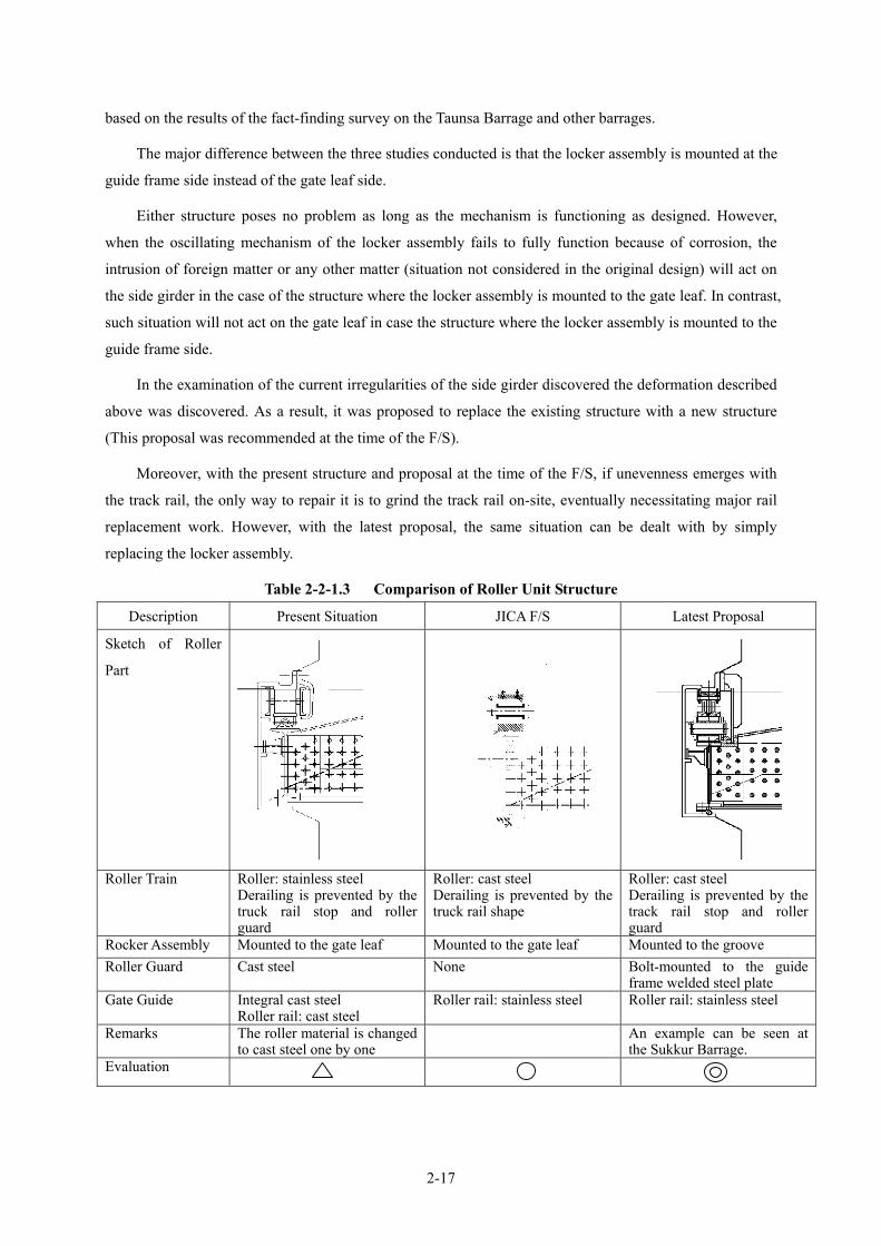
2-17
based on the results of the fact-finding survey on the Taunsa Barrage and other barrages.
The major difference between the three studies conducted is that the locker assembly is mounted at the
guide frame side instead of the gate leaf side.
Either structure poses no problem as long as the mechanism is functioning as designed. However,
when the oscillating mechanism of the locker assembly fails to fully function because of corrosion, the
intrusion of foreign matter or any other matter (situation not considered in the original design) will act on
the side girder in the case of the structure where the locker assembly is mounted to the gate leaf. In contrast,
such situation will not act on the gate leaf in case the structure where the locker assembly is mounted to the
guide frame side.
In the examination of the current irregularities of the side girder discovered the deformation described
above was discovered. As a result, it was proposed to replace the existing structure with a new structure
(This proposal was recommended at the time of the F/S).
Moreover, with the present structure and proposal at the time of the F/S, if unevenness emerges with
the track rail, the only way to repair it is to grind the track rail on-site, eventually necessitating major rail
replacement work. However, with the latest proposal, the same situation can be dealt with by simply
replacing the locker assembly.
Table 2-2-1.3 Comparison of Roller Unit Structure
Description Present Situation JICA F/S Latest Proposal
Sketch of Roller
Part
Roller Train Roller: stainless steel
Derailing is prevented by the truck rail stop and roller guard
Roller: cast steel Derailing is prevented by the truck rail shape
Roller: cast steel Derailing is prevented by the track rail stop and roller guard
Rocker Assembly Mounted to the gate leaf Mounted to the gate leaf Mounted to the groove Roller Guard Cast steel None Bolt-mounted to the guide
frame welded steel plate Gate Guide Integral cast steel
Roller rail: cast steel Roller rail: stainless steel Roller rail: stainless steel
Remarks The roller material is changed to cast steel one by one
An example can be seen at the Sukkur Barrage.
Evaluation

2-18
The parts that will be subjected for rehabilitation are shown in Figure 2-2-1.3.
設計外の曲げモーメント作用
水 圧 水 圧
ローラ片当り
Existing Latest Proposal
Figure 2-2-1.4 Comparison of Roller Structures Figure 2-2-1.5 State of Side Girder
Deformation
Partial contact
Figure 2-2-1.3 Subject Parts for Rehabilitation
Moment
Water Pressure Water Pressure

2-19
③ Number of Gates to be Rehabilitated
The JICA F/S and the Preliminary Study have already confirmed the deteriorating condition of the
gates (visual external inspection and plate thickness test, etc.) and problems with the hoists (visual external
inspection and operating capacity test).
Besides the results of these preceding studies, the gates requiring urgent rehabilitation have been
re-examined by the rehabilitation records in the last five years.
This is because of the judgement that any findings of a single survey can be significantly affected by
the contents of the maintenance work conducted during the previous year as those gates with problems are
usually repaired every year during the annual closure. Figure 2-2-1.6 compares the gates that are judged
to be problematic during the F/S in 1998, the Preliminary Study in 2003 and the present Study. Because of
frequent repairs, the gates with problems vary depending on the study timing. For example, Gate No. 34
which was ranked priority in terms of rehabilitation at the time of the F/S, does not anymore require
rehabilitation at the time of the Preliminary Study.
Figure 2-2-1.7 shows the classification results of the repair records in the last five years based on the
following three levels.
Level 1: rehabilitation of the roller train
Level 2: rehabilitation of the roller train and truck rail
Level 3: rehabilitation of the roller train, truck rail and components of the hoist
It was agreed that the criteria for rehabilitation gates will be based on any of the following:
① Gate which has been classified at Level 2 at least twice
② Gate which has been classified as Level 3 even once
As a result, 22 weir gates listed below were proposed to be rehabilitated (excluding three gates on the
right bank side of which the conversion to under sluice gates is planned).
10, 11, 12, 13, 14, 15, 16, 17, 18, 19, 20,
23, 24, 25, 26, 27, 31, 33, 35, 38, 55, 58
④ Heightening Methods of Weir Gate
There are two methods of heightening weir gate.
• Heightening at the Bottom
• Heightening at the Top
Comparison of heightening methods of weir gates is shown in table 2-2-1.4.Heightening at the bottom
is selected as the heightening method for the weir gates because of lesser impact on the existing gate.

2-20
Note: An asterisk (*) indicates that the gates not subject to rehabilitation at the time of the F/S but were subsequently
judged to require rehabilitation by the Preliminary Study. The gates with were dropped from the
scope of rehabilitation after the Preliminary Study even though their rehabilitation were considered necessary at the
time of the F/S.
Figure 2-2-1.6 Comparison of Subject Gates for Rehabilitation
Trouble Mentenance Trouble ranking Mentenance Trouble Mentenance Trouble Mentenance Trouble Mentenance Trouble Mentenance Trouble Mentenance Trouble Mentenance
1 12 23 34 45 56 67 78 89 9
10 ■ 24 ■ 1011 ■ 7 ■ ■ 1112 ■ 12 ■ ■ 1213 32 ■ 1314 ■ 5 ■ ■ 1415 ■ 5 ■ ■ 1516 ■ 4 ■ ■ 1617 ■ 7 ■ ■ 1718 ■ 2 ■ ■ 1819 ■ 7 ■ ■ 1920 ■ 3 ■ ■ 2021 45 2122 41 2223 ■ 23 ■ 2324 29 ★ ■ 2425 25 ■ 2526 35 ■ 2627 25 ■ 2728 25 2829 35 2930 ■ 11 3031 49 ■ 3132 ■ 14 3233 ■ 14 ■ 3334 ■ 1 3435 35 ■ ■ 3536 ■ 13 ■ 3637 41 ★ 3738 51 ★ ■ 3839 50 ★ 3940 ■ 14 4041 33 4142 40 4243 29 4344 ■ 14 ■ 4445 38 4546 38 4647 ■ 10 ■ 4748 25 4849 44 4950 52 5051 41 5152 ■ 14 ■ 5253 ■ 14 ■ 5354 ■ 14 ■ 5455 45 ■ ■ 5556 ■ 14 ■ 5657 33 ★ 5758 45 ★ ■ 5859 45 5960 ■ 14 6061 29 6162 6263 6364 6465 65
GateNo.
1998 1999 2000 GateNo.
-1998 2002 2003 20042001

Note
s;A
ction o
f R
epa
ir
1: R
epa
ir o
f R
olle
r Tra
in2: R
epa
ir o
f R
olle
r Tra
in + W
eld
ing
of R
ocke
r A
ssem
bly
3: R
epa
ir o
f R
olle
r Tra
in+W
eld
ing
of R
ocke
r A
ssem
bly
+R
epl
ace o
f B
ear
ing
Blo
cks
of H
ois
t
: R
ecom
mend
to R
epa
lace
M
ain G
ates:
22 (e
xcept
No.5
9, 60)
Rule
s fo
r D
ecis
ion o
f R
epl
acem
ent
1. T
he C
ase C
ounte
d R
ank"
3" m
ore
than
one(1
) tim
e.
2. T
he C
ase C
ounte
d R
ank"
2"m
ore
than
tw
o(2
) tim
es.
No.1
0123
2000
2001
2002
2003
2004
No.2
0123
2000
2001
2002
2003
2004
No.4
0123
2000
2001
2002
2003
2004
No.5
0123
2000
2001
2002
2003
2004
No.6
0123
2000
2001
2002
2003
2004
No.7
0123
2000
2001
2002
2003
2004
No.8
0123
2000
2001
2002
2003
2004
No.9
0123
2000
2001
2002
2003
2004
No.1
0
0123
2000
2001
2002
2003
2004
No.1
1
0123
2000
2001
2002
2003
2004
No.1
2
0123
2000
2001
2002
2003
2004
No.1
3
0123
2000
2001
2002
2003
2004
No.1
4
0123
2000
2001
2002
2003
2004
No.1
5
0123
2000
2001
2002
2003
2004
No.1
6
0123
2000
2001
2002
2003
2004
No.1
7
0123
2000
2001
2002
2003
2004
No.1
8
0123
2000
2001
2002
2003
2004
No.1
9
0123
2000
2001
2002
2003
2004
No.2
0
0123
2000
2001
2002
2003
2004
No.2
1
0123
2000
2001
2002
2003
2004
No.2
2
0123
2000
2001
2002
2003
2004
No.2
3
0123
2000
2001
2002
2003
2004
No.2
4
0123
2000
2001
2002
2003
2004
No.2
5
0123
2000
2001
2002
2003
2004
No.2
6
0123
2000
2001
2002
2003
2004
No.2
7
0123
2000
2001
2002
2003
2004
No.2
8
0123
2000
2001
2002
2003
2004
No.2
9
0123
2000
2001
2002
2003
2004
No.3
0
0123
2000
2001
2002
2003
2004
No.3
1
0123
2000
2001
2002
2003
2004
No.3
2
0123
2000
2001
2002
2003
2004
No.3
3
0123
2000
2001
2002
2003
2004
No.3
4
0123
2000
2001
2002
2003
2004
No.3
5
0123
2000
2001
2002
2003
2004
No.3
6
0123
2000
2001
2002
2003
2004
No.3
7
0123
2000
2001
2002
2003
2004
No.3
8
0123
2000
2001
2002
2003
2004
No.3
9
0123
2000
2001
2002
2003
2004
No.4
0
0123
2000
2001
2002
2003
2004
No.4
1
0123
2000
2001
2002
2003
2004
No.4
2
0123
2000
2001
2002
2003
2004
No.4
3
0123
2000
2001
2002
2003
2004
No.4
4
0123
2000
2001
2002
2003
2004
No.4
5
0123
2000
2001
2002
2003
2004
No.4
6
0123
2000
2001
2002
2003
2004
No.4
7
0123
2000
2001
2002
2003
2004
No.4
8
0123
2000
2001
2002
2003
2004
No.4
9
0123
2000
2001
2002
2003
2004
No.5
0
0123
2000
2001
2002
2003
2004
No.5
1
0123
2000
2001
2002
2003
2004
No.5
2
0123
2000
2001
2002
2003
2004
No.5
3
0123
2000
2001
2002
2003
2004
No.5
4
0123
2000
2001
2002
2003
2004
No.5
5
0123
2000
2001
2002
2003
2004
No.5
6
0123
2000
2001
2002
2003
2004
No.5
7
0123
2000
2001
2002
2003
2004
No.5
8
0123
2000
2001
2002
2003
2004
No.5
9
0123
2000
2001
2002
2003
2004
No.6
0
0123
2000
2001
2002
2003
2004
No.6
1
0123
2000
2001
2002
2003
2004
No.6
2
0123
2000
2001
2002
2003
2004
No.6
3
0123
2000
2001
2002
2003
2004
No.6
4
0123
2000
2001
2002
2003
2004
No.6
5
0123
2000
2001
2002
2003
2004
No.3
0123
2000
2001
2002
2003
2004
2-21
Figu
re 2
-2-1
.7C
lass
ifica
tion
Res
ults
of t
he R
epai
rC
onte
nts i
n th
e L
ast F
ive
Yea
rs
Left
Unde
r Slu
ice
Gat
e
Nav
igat
ion
Lock
Gat
e
Weir G
ate
Weir G
ate
Rig
ht
Unde
r Slu
ice
Gat
e

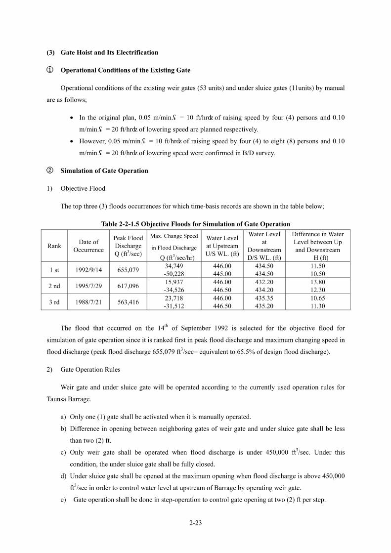
2-23
(3) Gate Hoist and Its Electrification
① Operational Conditions of the Existing Gate
Operational conditions of the existing weir gates (53 units) and under sluice gates (11units) by manual
are as follows;
• In the original plan, 0.05 m/min.(= 10 ft/hr)of raising speed by four (4) persons and 0.10
m/min.(= 20 ft/hr)of lowering speed are planned respectively.
• However, 0.05 m/min.(= 10 ft/hr)of raising speed by four (4) to eight (8) persons and 0.10
m/min.(= 20 ft/hr)of lowering speed were confirmed in B/D survey.
② Simulation of Gate Operation
1) Objective Flood
The top three (3) floods occurrences for which time-basis records are shown in the table below;
Table 2-2-1.5 Objective Floods for Simulation of Gate Operation
Rank Date of Occurrence
Peak Flood Discharge Q (ft3/sec)
Max. Change Speed
in Flood Discharge
⊿Q (ft3/sec/hr)
Water Level at UpstreamU/S WL. (ft)
Water Level at
Downstream D/S WL. (ft)
Difference in Water Level between Up and Downstream ⊿H (ft)
1 st 1992/9/14 655,079 34,749 -50,228
446.00 445.00
434.50 434.50
11.50 10.50
2 nd 1995/7/29 617,096 15,937 -34,526
446.00 446.50
432.20 434.20
13.80 12.30
3 rd 1988/7/21 563,416 23,718 -31,512
446.00 446.50
435.35 435.20
10.65 11.30
The flood that occurred on the 14th of September 1992 is selected for the objective flood for
simulation of gate operation since it is ranked first in peak flood discharge and maximum changing speed in
flood discharge (peak flood discharge 655,079 ft3/sec= equivalent to 65.5% of design flood discharge).
2) Gate Operation Rules
Weir gate and under sluice gate will be operated according to the currently used operation rules for
Taunsa Barrage.
a) Only one (1) gate shall be activated when it is manually operated.
b) Difference in opening between neighboring gates of weir gate and under sluice gate shall be less
than two (2) ft.
c) Only weir gate shall be operated when flood discharge is under 450,000 ft3/sec. Under this
condition, the under sluice gate shall be fully closed.
d) Under sluice gate shall be opened at the maximum opening when flood discharge is above 450,000
ft3/sec in order to control water level at upstream of Barrage by operating weir gate.
e) Gate operation shall be done in step-operation to control gate opening at two (2) ft per step.

2-24
3) Simulation for Manual Gate Operation
The result of simulation for manual gate operation on flood that occurred on the 14th of September
1992 is shown below (peak flood discharge:655,079 ft3/sec = equivalent to 65.5% of design flood
discharge)(refer to Table 2-2-1.6).
a) Four (4) gates must be operated simultaneously since required maximum raising speed of gate
become 32.00 ft/hr(0.16 m/min.)at 1:00 AM in 14th September 1992.
b) Three (3) gates must be operated simultaneously since required maximum raising speed of gate
become 54.00 ft/hr(0.27 m/min.)at 10:00 AM in 15th September 1992.
c) The time zone in which manual operation (simultaneous operation of one gate with 0.05m/min.=10
ft/hr of raising speed and 0.10 m/min.=20 ft/hr of lowering speed) cannot be done will be 15 hours
in total, eight (8) hours in raising and seven (7) hours in lowering, (equivalent to 8.9% of seven (7)
days of flooding period)
③ Electrification of Gate Hoist
The results of simulation for manual gate operation show that eight (8) hours delay in raising
operation during seven (7) days of flooding period will occur and water level at upstream will rise as a
result, and long operation of 111 hours by manual operation (equivalent to 66.1% of seven (7) days
flooding period) will be required. Therefore, current operation system (10 to 12 persons x 3 shifts) needs to
be strengthened to four (4) times or raising speed must be improved.
Other barrages already rehabilitated in Punjab Province have been powered by electricity. Therefore
gates operated by electricity become indispensable for efficient operation, accurate water control and
discharge management.
In addition, objective for electrified gate hoist is planned only for leaves to be rehabilitated. The
reason for this is that gate leaf might be broken and some serious problems might occur if electrification of
gate hoist only leaving leaf structure is not improved.
Though various parts of the gate hoist are generally well managed at present, it is proposed to replace
drum and drum gear along with change of power source because of necessity of replacement due to its
strength in structure (described later about examination of strength).
Since it was clarified through the latest field survey that there are many problems with middle gear
system in the present structure of gate hoist, it is proposed to change part of the middle gear of the chain
structure to the system where the whole gate hoist will be placed at the upper deck.

2-
25
Tabl
e 2-
2-1.
6 S
imul
atio
n fo
r G
ate
Ope
ratio
n(Fl
ood
on 1
4th
Sept
embe
r 19
92)
Wei
r Gat
e G
roup
A
Wei
r gat
e G
roup
B
Und
er S
luic
e G
ate
Gro
up A
U
nder
Slu
ice
Gat
e G
roup
B
Tota
l D
isch
arge
Q
(ft3 /s
ec)
Tota
l O
peni
ng
∑a
(ft)
Dat
e an
d Ti
me
Dis
char
geQ
(f
t3 /sec
)
Diff
eren
ce
in
Dis
char
ge(f
t3 /sec
)
Wat
er L
evel
at
Ups
tream
U
/S W
L.
(ft)
Wat
er L
evel
at
D
owns
tream
D/S
WL.
(ft)
Ope
nin
g a 1
(ft)
No.
of
ga
tes
N
(Uni
t)
Dis
char
geQ
1
(ft3 /s
ec)
Ope
nin
g a 2
(ft)
No.
of
ga
tes
N
(Uni
t)
Dis
char
ge Q
2 (f
t3 /sec
)
Ope
ning
a 3
(ft)
No.
of
Gat
esN
(U
nit)
Dis
char
geQ
3 (f
t3 /sec
)
Ope
nin
g a 4
(ft)
No.
of
gate
N
(U
nit)
Dis
char
geQ
4 (f
t3 /sec
)
Ope
ning
Sp
eed
Vg
(ft/h
r)
9/10
00
:00
256,
167
044
6.50
43
1.00
4.00
5023
5,85
56.
003
20,4
090.
0011
02.
000
025
6,26
40
0.00
9/
11
18:0
0 33
4,95
178
,784
444.
00
431.
906.
0050
311,
537
8.00
323
,678
0.00
110
2.00
00
335,
214
106
2.52
9/
11
22:0
0 37
6,34
541
,394
444.
00
432.
106.
0025
156,
062
8.00
2822
1,45
20.
0011
02.
000
037
7,51
450
12
.50
9/12
00
:00
376,
345
044
4.00
43
2.10
6.00
2515
6,06
28.
0028
221,
452
0.00
110
2.00
00
377,
514
0 0.
00
9/12
01
:00
404,
649
28,3
0444
4.00
43
2.20
6.00
956
,262
8.00
4434
8,53
90.
0011
02.
000
040
4,80
032
32
.00
9/12
06
:00
404,
649
044
4.00
43
2.20
6.00
956
,262
8.00
4434
8,53
90.
0011
02.
000
040
4,64
90
0.00
9/
13
03:0
0 52
5,64
212
0,99
344
5.00
43
3.85
8.00
3730
7,47
010
.00
1615
7,90
04.
008
39,8
086.
003
21,6
1952
6,79
710
0 4.
76
9/13
04
:00
542,
364
16,7
2244
5.00
43
3.90
8.00
3730
7,79
310
.00
1615
8,08
34.
001
4,98
06.
0010
72,1
1954
2,97
514
14
.00
9/13
05
:00
542,
364
044
5.00
43
3.90
8.00
3730
7,79
310
.00
1615
8,08
34.
001
4,98
06.
0010
72,1
1954
2,97
50
0.00
9/
13
09:0
0 54
4,47
22,
108
445.
00
434.
058.
0037
308,
033
10.0
016
158,
220
6.00
643
,296
8.00
546
,327
555,
875
12
3.00
9/
13
10:0
0 56
9,17
814
,706
445.
00
434.
108.
0037
308,
331
10.0
016
158,
389
8.00
1092
,726
10.0
01
11,1
2857
0,57
414
14
.00
9/13
12
:00
569,
178
044
5.00
43
4.10
8.00
3730
8,33
110
.00
1615
8,38
98.
0010
92,7
2610
.00
111
,128
570,
574
0 0.
00
9/13
20
:00
599,
587
30,4
0944
5.50
43
4.25
8.00
3731
4,76
110
.00
1616
2,04
38.
000
010
.00
1112
4,65
059
9,58
720
2.
50
9/13
21
:00
634,
336
34,7
4944
6.00
43
4.50
8.00
3732
1,14
710
.00
1616
5,66
412
.00
911
9,55
213
.00
228
,157
634,
520
24
24.0
0 9/
13
22:0
0 64
0,33
05,
994
446.
00
434.
558.
0037
321,
269
10.0
016
165,
733
12.0
02
26,5
7713
.00
912
6,75
664
0,33
47
7.00
9/
15
07:0
0 60
6,11
7-3
4,21
344
5.00
43
5.00
8.00
4335
9,23
910
.00
1099
,271
13.0
011
149,
040
15.0
00
060
7,54
9-1
2 -0
.36
9/15
08
:00
585,
278
-20,
839
445.
00
434.
806.
003
19,6
568.
0050
417,
116
13.0
011
148,
823
15.0
00
058
5,59
5-2
6 -2
6.00
9/
15
09:0
0 55
5,45
7-2
9,82
144
5.00
43
4.70
6.00
1912
4,26
48.
0034
283,
075
13.0
011
148,
526
15.0
00
055
5,86
5-3
2 -3
2.00
9/
15
10:0
0 50
5,22
9-5
0,22
844
5.00
43
4.50
6.00
4629
9,99
28.
007
58,0
9813
.00
1114
8,06
015
.00
00
506,
151
-54
-54.
00
9/15
11
:00
505,
229
044
5.00
43
4.50
6.00
4629
9,99
28.
007
58,0
9813
.00
1114
8,06
015
.00
00
506,
151
0 0.
00
9/15
12
:00
479,
502
-25,
727
445.
00
434.
404.
006
27,1
886.
0047
306,
097
13.0
011
147,
838
15.0
00
048
1,12
2-2
6 -2
6.00
9/
15
15:0
0 47
9,50
20
445.
00
434.
404.
006
27,1
886.
0047
306,
097
13.0
011
147,
838
15.0
00
048
1,12
20
0.00
9/
15
18:0
0 46
6,63
9-1
2,86
344
5.00
43
4.50
4.00
1358
,871
6.00
4026
0,33
713
.00
1114
7,73
115
.00
00
466,
939
-14
-4.6
7 9/
15
21:0
0 37
9,28
9-8
7,28
944
5.00
43
4.00
4.00
1358
,656
6.00
4025
9,29
84.
007
34,6
436.
004
28,6
5738
1,25
3-9
1 -3
0.33
9/
16
00:0
0 36
6,65
0-1
2,70
044
5.00
43
3.90
4.00
1358
,628
6.00
4025
9,16
52.
002
5,11
44.
009
44,5
2336
7,43
0-1
2 -4
.00
9/17
00
:00
251,
949
-114
,701
445.
00
430.
304.
0045
202,
223
6.00
851
,632
0.00
110
2.00
00
253,
855
-104
-4
.33
2-25

2-26
(4) Electrification and Operating Method
① Subjects of Electrification
The gates proposed to be electrified are the gates are to be rehabilitated as described earlier.
② Operating Method
When the hoist is electrified, the gate can be operated from the motor (local) side or by remote control.
The results of the fact-finding survey on other electrified barrages indicate the limited use of a remote
control mechanism as gates are usually operated from the motor side.
• Used only during the flood season (Chashma Barrage)
• Not used (Marala Barrage)
The planned rehabilitation does not feature additional monitoring devices. As such, the use of remote
control can be very dangerous as the gates will be operated without visual confirmation. Together with the
actual situation of remote control operation, it has been decided to plan gate operation from the motor
(local) side only.
(5) Rehabilitation of Superstructure Deck
With the electrification of the hoist, the upper deck will be rehabilitated for the purpose of improving
its maintainability. As the latest field survey has found that dispersion of the control floor poses a problem
in terms of operability as well as structure, the drum and drum gears will be placed at the uppermost deck
to make the hoist located on a single floor in order to improve the structure, operability, maintainability and
safety.
Following such improvement, reinforcement of the superstructure will be necessary. Meanwhile, this
improvement will enable the omission of a platform for gear maintenance as will be described later.
(6) Painting of Superstructure Deck
As painting of the upper deck is part of the normal inspection and repair work, the exclusion of this
painting work from the planned rehabilitation work is proposed.
(7) Rehabilitation of Hoisting Drum and Gears
As indicated by the past study results, the maintenance conditions of each component of the hoist are
generally good. However, the planned change to power source will necessitate a change of the drum and
drum gears to increase their structural strength and, therefore, these will be replaced as part of the planned
rehabilitation work.
Table 2-2-1.7 shows the examination results of the drum gear strength after electrification. Neither the
bending strength of the gears nor the bearing strength of the tooth surface satisfies their respective current
reference value.

2-27
Table 2-2-1.7 Calculation Results of Gear Strength
Safety Factor for Bending Strength Safety Factor for Bearing Strength Items
Calculated Value Allowable Value Calculated Value Allowable Value
At Rated Operation 1.2 5.0 0.05 1.0
(8) Platform for Gear Maintenance
As already described earlier, the present proposal calls for the installation of hoist at the upper deck.
Accordingly, the originally planned platform for gear maintenance will no longer be required. Therefore,
the omission of this platform from the rehabilitation plan is possible.
2-2-1-5 Bulkhead Gates
(1) Possibility of Using Bulkhead Gates for Other Barrages
An enquiry was made with the Pakistan side regarding the converted use of bulkhead gates for other
barrages. The recommended suitable places were the Jinnah Barrage and the Trimu Barrage.
These recommended sites were then analysed from the two points described below. It was concluded
that converted use at these two barrages would be most effective. The use of two bulkhead gates at each
barrage, including the Taunsa Barrage, will be possible. All five gates may be used as single barrage in case
of barrage rehabilitation.
① Checking of Possibility of Converted Use of Bulkhead Gates
Barrages in Punjab Province are classified into three phases based on their respective year of
construction. Phase I barrages were rehabilitated around 1970 under a World Bank project. At the time of
the implementation of the World Bank assisted project, the barrages constructed in Phase III were not due
for rehabilitation and, therefore, have never been rehabilitated. All of the barrages constructed in Phase II
are gateless head works. In contrast, those constructed in Phase III have gates with a span of 18 m.
Based on Table 2-2-1.8, possible sites for the converted use of the bulkhead gates after use at the
Taunsa Barrage are restricted to the Jinnah and the Trimu Barrage if they would be used only for
rehabilitation work.

2-28
Table 2-2-1.8 Barrages in Punjab
Notes
1) The number of years since construction or rehabilitation 2) O Within 40years of construction or rehabilitation is colour coded in the following manner
0 – 20 years over 100years ☆ Within 40-60 years of construction or rehabilitation 20 – 40 years 40 – 60 years Rehabilitation conducted ★ More than 60 years since construction rehabilitation 60 – 80 years 80 – 100years
② Checking of Structural Dimensions of Jinnah Barrage and Trimu Barrage
The structural dimensions of the barrage and gates of these two barrages to be considered as
preferential sites for the converted use of the bulkhead gates were checked and are shown in Table 2-2-1.9.
Table 2-2-1.9 Structural Dimensions of Two Barrages
Jinnah Trimu Taunsa
Span (L) 18 m (60 feet) 18 m (60 feet) 18 m (60 feet)
Height (H) (Sediment Discharge Gate) 5.5 m (18 feet) 5.5 m (18 feet) 6.7 m (22 feet)
Height (H) (Floodgate) 4.6 m (15 feet) 4.7 m (15.5 feet) 6.0 m (20 feet)
At the Trimu Barrage, work to replace the lower part of the gate is in progress because of the evident
corrosion of the gate leaf members. Given this situation, it is anticipated that the gate rehabilitation work
will take place fairly soon in the coming years.
(2) Validity of Temporary Cofferdam Method for Barrage Rehabilitation
Due to the following objectives, introduction of new bulkhead gates is proposed for the rehabilitation
of Barrage and future O & M;
1)
1890 1900 1910 1920 1930 1940 1950 1960 1970 1980 1990 2000 2010
Khanki 1892 ★
Sidhnai 1897 1965 ○
Rasul 1901 1974 ○
Malara 1912 1968 ○
Baloki 1913 H/W -
Qadirabad 1967? 1967 ? ○
Chashima 1971 ○
Slemanki 1927 H/W -
Isram 1928 H/W -
Punjunad 1929 H/W? -?
Trimmu 1939 ★
Jinnah 1946 ☆
Taunsa 1958 ☆
ConditionName Construct Repair Type
Ⅰ
Ⅱ
Ⅲ
2)

2-29
• Temporary cofferdam works at upstream of the Barrage for gate rehabilitation by grant aid
project
• Temporary cofferdam works upstream of the Barrage for the rehabilitation of gate, and civil
works on barrage body and apron to be done by Pakistan side.
• Temporary cofferdam works at upstream of the Barrage for annual O & M repairing works
such as repainting of gates after completion of rehabilitation works of Barrage.
Generally there are three (3) methods in temporary cofferdam that have actually been employed so far,
1) bulkhead gate method, 2) stop-log gate method, and 3) cofferdam by steel sheet plate. When determining
optimum method, efficiency in function, water seal, installation and removal, economy and availability for
repeated-use etc must be examined comprehensively.
Table 2-2-1.10 Comparison Table of Temporary Cofferdam Methods to be Selected
Methods Bulkhead Gate Methods Stop-Log Gate Method Cofferdam by Steel Sheet Pile Method
Structure
Outline of Structure
1) Leaf type is sealed box structure.
2) Pouring & drainage devices will be equipped to install or float leaves.
3) It is necessary for leaves to fix in preparation to reversed water pressure.
1) Leaf type is plate girder structure. 2) Mid-piers are necessary, which will
be fixed by anchor on piers’ bottom and supporting apron.
3) To be sealed with pier and part of steel at bottom.
1) Double cofferdam structure with steel sheet pile.
2) Banking is necessary to install steel sheet pile since concrete apron or rubble foundation established on foundation ground.
Function
1) Availability in response to difference in gate span to some extent. ◎
1) Two (2) piers will be necessary due to long gate span with 18.8m. ○
1) Steel sheet pile of IV type x 9.0 m length will be necessary due to 8.5m height of temporary cofferdam.
2) It is difficult to IV typed steel sheet pile in Pakistan.
△
Water Seal
1) Small water leak is predicted due to water seal with water pressure.
2) In rehabilitation, small water leak can be drained by drainage pump.
3) Some water leak is allowed considering future O&M(repainting etc)
○
1) Considerable water leak is predicted due to long water seal with mid-piers, bottom and part of mid-connecting.
2) Large scale drainage will be necessary for considerable leak of water in rehabilitation works.
3) Difficulty is predicted in O&M (repainting etc) due to considerable leak of water.
△
1) Adequate depth for sheet pile cannot be secured because of existence of concrete apron or rubble foundation on foundation ground.
2) Considerable seepage from foundation ground is predicted due to inadequate depth of steel sheet pile.
3) In rehabilitation, dewatering works by deep well etc is necessary due to difficulty for drainage of considerable seepage by drainage pump.
△
Bulkhead gate
WL
h
Sheet Pile
B = 0.8 - 1.2h
Embankment
中間支柱
角落しゲートStop-logSupport

2-30
Methods Bulkhead Gate Methods Stop-Log Gate Method Cofferdam by Steel Sheet Pile Method
Installation and Removal or Construction
1) Leaf will be floated on canal surface with incline and towed to the site by tugboat.
2) Leaves will be installed by pouring water into them.
3) When removing to store in stockyard, adverse procedure of 2) will be taken.
4) Special technology is necessary when installing and removing.
5) It will take about two(2) days to install and remove one (1) leaf.
◎
1) Installation and removal of middle piers will be done in diving operation since water depth will be predicted to be about 7.0m.
2) Difficulty is predicted for diving operation due to low degree of water clearness.
3) Since installation and removal of stop-log will be done by crane placed on attached road bridge, closure of attached road bridge will be necessary for this period.
4) It will take about five (5) days for installation and removal of one (1) leaf.
×
1) Large quantity of soil will be necessary (about 2,500 m3) to install steel sheet piles into banking, and it will take about five (5) days to install and remove banking from work barge.
2) It will take about 20 days to install and remove steel sheet piles and soil from work barge per one (1) leaf.
×
Availability for Application to the Existing
Piers of Barrage
1) It is necessary to heighten water seal efficiency by installing steel plates on the existing apron and to lay underground steel as guide frame at a side of piers.
2) More than three (3) m is necessary between downstream of Bulkhead gate and upstream of the gate to secure space for rehabilitation works. For the purpose, it is necessary to pay attention to leaf’s shape of Bulkhead gate.
○
1) Slot for stop-log is necessary on the piers to support leaves.
2) Necessary space for rehabilitation works is not secured because there is only 2.1 m to set a slot for stop-log on the existing piers.
×
1) No impact is predicted on the existing piers since temporary cofferdam will be established at a distant from the existing piers.
2) Necessary space for rehabilitation works will be secured freely.
◎
Repeat-use 1) Possible ◎ 1) Possible ◎ 1) Impossible ×
Diverted use for Other Barrages
1) Repeat-use is possible for a barrage with less than 22ft height of leaves since gate span and thickness of pier for large scale barrage are unified in Pakistan.
2) Newly installation of steel plate for Bulkhead gate and steel for guide frame is also necessary.
◎
1) Repeat-use is possible for a barrage with less than 22ft height of leaves since gate span and thickness of pier for large scale barrage are unified in Pakistan.
2) Newly installation of steel plate for Bulkhead gate and steel for guide frame is also necessary.
△
1) Repeat-use in other barrages is impossible.
×
Economical Efficiency
1) Duration in year:50 years
2) Usable 91 times with repainting every 7 years.
3) Economical efficiency (per one temporary cofferdam with one gate):3,503 thousand Yen
△
1) Duration in year:50 years 2) Includes cost to water leakage.3) Usable 91 times with
repainting every 7 years. 4) Economical efficiency (per one
temporary cofferdam with one gate):3,651 thousand Yen
◎
1) Installation and removal will be done seven (7) times for 50 years.
2) It includes cost to drain seepage water from foundation ground.
3) Economical efficiency (per one temporary cofferdam with one gate):11,360 thousand Yen
×
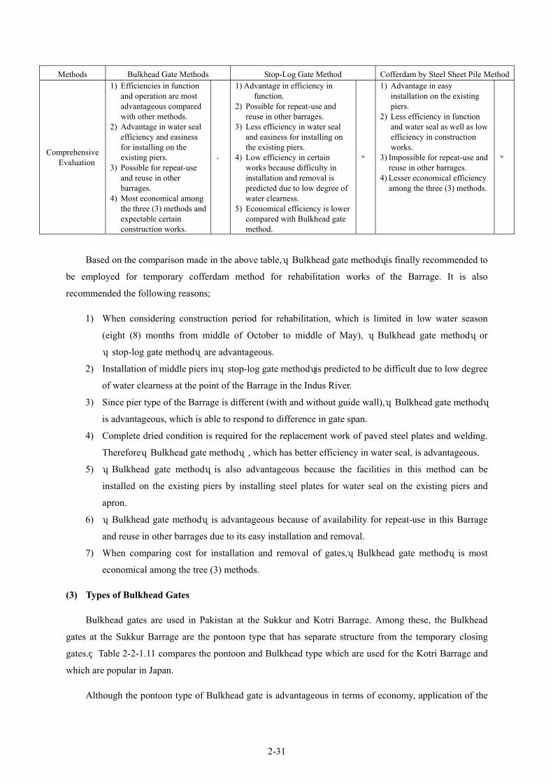
2-31
Methods Bulkhead Gate Methods Stop-Log Gate Method Cofferdam by Steel Sheet Pile Method
Comprehensive Evaluation
1) Efficiencies in function and operation are most advantageous compared with other methods.
2) Advantage in water seal efficiency and easiness for installing on the existing piers.
3) Possible for repeat-use and reuse in other barrages.
4) Most economical among the three (3) methods and expectable certain construction works.
◎
1) Advantage in efficiency in function.
2) Possible for repeat-use and reuse in other barrages.
3) Less efficiency in water seal and easiness for installing on the existing piers.
4) Low efficiency in certain works because difficulty in installation and removal is predicted due to low degree of water clearness.
5) Economical efficiency is lower compared with Bulkhead gate method.
×
1) Advantage in easy installation on the existing piers.
2) Less efficiency in function and water seal as well as low efficiency in construction works.
3) Impossible for repeat-use and reuse in other barrages.
4) Lesser economical efficiency among the three (3) methods.
×
Based on the comparison made in the above table, 「Bulkhead gate method」is finally recommended to
be employed for temporary cofferdam method for rehabilitation works of the Barrage. It is also
recommended the following reasons;
1) When considering construction period for rehabilitation, which is limited in low water season
(eight (8) months from middle of October to middle of May), 「Bulkhead gate method」or
「stop-log gate method」are advantageous.
2) Installation of middle piers in 「stop-log gate method」is predicted to be difficult due to low degree
of water clearness at the point of the Barrage in the Indus River.
3) Since pier type of the Barrage is different (with and without guide wall), 「Bulkhead gate method」
is advantageous, which is able to respond to difference in gate span.
4) Complete dried condition is required for the replacement work of paved steel plates and welding.
Therefore「Bulkhead gate method」, which has better efficiency in water seal, is advantageous.
5) 「Bulkhead gate method」is also advantageous because the facilities in this method can be
installed on the existing piers by installing steel plates for water seal on the existing piers and
apron.
6) 「Bulkhead gate method」is advantageous because of availability for repeat-use in this Barrage
and reuse in other barrages due to its easy installation and removal.
7) When comparing cost for installation and removal of gates,「Bulkhead gate method」is most
economical among the tree (3) methods.
(3) Types of Bulkhead Gates
Bulkhead gates are used in Pakistan at the Sukkur and Kotri Barrage. Among these, the Bulkhead
gates at the Sukkur Barrage are the pontoon type that has separate structure from the temporary closing
gates. Table 2-2-1.11 compares the pontoon and Bulkhead type which are used for the Kotri Barrage and
which are popular in Japan.
Although the pontoon type of Bulkhead gate is advantageous in terms of economy, application of the

2-32
pontoon type to the Taunsa Barrage is difficult from the structural point of view. The Bulkhead type is
superior to the pontoon type when the operability, water tightness and converted use for another barrage are
taken into consideration. Given the particularly large number of barrages for management in Punjab
Province, the prospective converted use for other barrages must be taken into consideration as rehabilitation
work is already planned for the Trimu and Jinnah Barrage which will certainly be followed by other
barrages in the future. For these reasons, the Bulkhead type will be adopted for the present Project.
Table 2-2-1.11 Comparison of Bulkhead Gate Types
Descriptions Pontoon Type Bulkhead Type
General Drawings
Watertight Performance
As side water tightness is structurally required, water tightness must be done at the sides of the barrage piers. As the watertight performance is easily affected by the completed conditions of these piers, the water tightness at the sides is inferior.
As the water tightness is structurally done at the top of the barrage piers, the impact of the completion conditions of the piers is less prominent compared to the pontoon type, providing a better watertight performance.
Application to Taunsa Barrage
Because the upstream piers are shorter at the Taunsa Barrage, the Bulkhead gate must be fairly near the main gate to secure the side water tightness, making the clearance to the main gate very small. The application of the radial type to the Taunsa Barrage is impossible as its arched gate would make the gate nearer the downstream main gate, leaving a space of only some 500 mm for work.
As water tightness is established at the top of the barrier piers, sufficient clearance to the main gate can be secured, causing no obstacle to rehabilitation work.
Converted Use for Other Barrage
Difficult to divide the gate. Possible to divide the gate.
Economy 90% The pontoon can be shared; good economy if the number of gates is large.
100% Slightly disadvantageous from an economic point of view.
Judgement Functionally, it is difficult to apply the pontoon type to the Taunsa Barrage and this type, therefore, is not employed.
Functionally, its use for the Taunsa Barrage has no problems and, therefore, this type is employed.
(4) Gate Numbers of Bulkhead Gates
Study on the required number of the Bulkhead gates was made considering ① the most optimum
scale in terms of project economy based on the gate numbers and rehabilitation periods and ② adequate
operation and maintenance works for the rehabilitated gates after the implementation of the project.
Finally, it was concluded that the most optimum numbers of gate is 5.
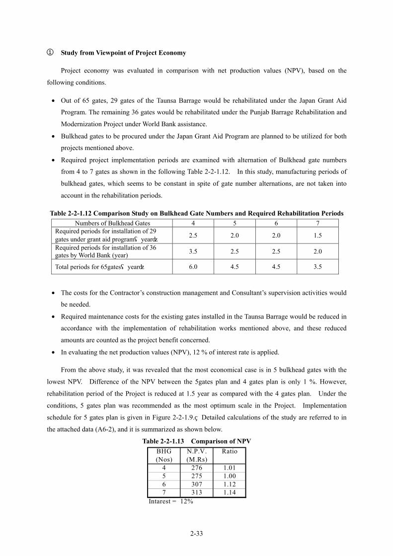
2-33
① Study from Viewpoint of Project Economy
Project economy was evaluated in comparison with net production values (NPV), based on the
following conditions.
• Out of 65 gates, 29 gates of the Taunsa Barrage would be rehabilitated under the Japan Grant Aid
Program. The remaining 36 gates would be rehabilitated under the Punjab Barrage Rehabilitation and
Modernization Project under World Bank assistance.
• Bulkhead gates to be procured under the Japan Grant Aid Program are planned to be utilized for both
projects mentioned above.
• Required project implementation periods are examined with alternation of Bulkhead gate numbers
from 4 to 7 gates as shown in the following Table 2-2-1.12. In this study, manufacturing periods of
bulkhead gates, which seems to be constant in spite of gate number alternations, are not taken into
account in the rehabilitation periods.
Table 2-2-1.12 Comparison Study on Bulkhead Gate Numbers and Required Rehabilitation Periods Numbers of Bulkhead Gates 4 5 6 7
Required periods for installation of 29 gates under grant aid program(year) 2.5 2.0 2.0 1.5
Required periods for installation of 36 gates by World Bank (year) 3.5 2.5 2.5 2.0
Total periods for 65gates(year) 6.0 4.5 4.5 3.5
• The costs for the Contractor’s construction management and Consultant’s supervision activities would
be needed.
• Required maintenance costs for the existing gates installed in the Taunsa Barrage would be reduced in
accordance with the implementation of rehabilitation works mentioned above, and these reduced
amounts are counted as the project benefit concerned.
• In evaluating the net production values (NPV), 12 % of interest rate is applied.
From the above study, it was revealed that the most economical case is in 5 bulkhead gates with the
lowest NPV. Difference of the NPV between the 5gates plan and 4 gates plan is only 1 %. However,
rehabilitation period of the Project is reduced at 1.5 year as compared with the 4 gates plan. Under the
conditions, 5 gates plan was recommended as the most optimum scale in the Project. Implementation
schedule for 5 gates plan is given in Figure 2-2-1.9. Detailed calculations of the study are referred to in
the attached data (A6-2), and it is summarized as shown below.
Table 2-2-1.13 Comparison of NPV BHG N.P.V. Ratio(Nos) (M.Rs)
4 276 1.015 275 1.006 307 1.127 313 1.14
Intarest = 12%

2-34
Figure 2-2-1.8 Relation between Bulkhead Gate Numbers and NPV
② Study from Viewpoint of Operation and Maintenance after Project Implementation
Effective periodical gate operation and maintenance and improvement works, such as gate repainting,
gate improvement, regulatory structure improvement, etc. could be expected after project implementation
by using the introduce bulkhead gates. In studying the adequate number of bulkhead gates from the
operation and maintenance viewpoints, data from other related barrages were used.
In case of the Kotri barrage constructed in Sind Province, 3 sets of bulkhead gates have been installed.
Barrage and related facilities have been properly maintained and in good conditions utilizing the bulkhead
gates. Utilization records of bulkhead gates in the Kotri Barrage are given below.
Maintenance Period: 1.5 month/gate
No. of Bulkhead gates: 3 gates
Total no. of gates: 45 gates
According to the data, the installed gates have been maintained and improved once every 2years on
the average (45 x 1.5 / 3 / 12 = 1.9 year).
If the operation and maintenance works of the Taunsa Barrage would be undertaken in the same
frequency as the Kotri Barrage, the required number of bulkhead gates for the Taunsa Barrage is estimated
at 5 gates as shown below.
65gates / 45gates x 3 gates = 4.3 gates,
Say 5 gates
Relation between Units of Bulk Head Gate and Net Present Value
250
270
290
310
330
350
4 5 6 7
Units of Bulk Head Gate
Net
Pre
sent
Valu
e(M
illion
Rs)
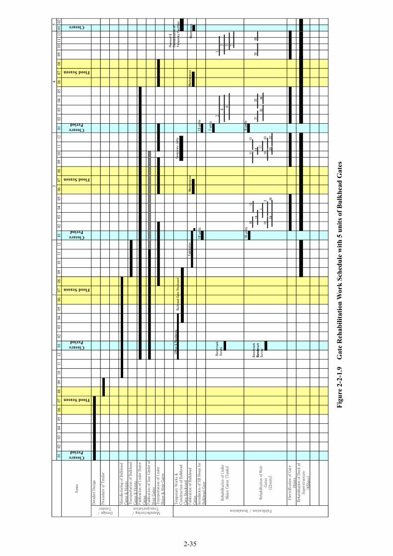
2-35
Figu
re 2
-2-1
.9
Gat
e R
ehab
ilita
tion
Wor
k Sc
hedu
le w
ith 5
uni
ts o
f Bul
khea
d G
ates
2-35
12
34
0102
0304
0506
0708
0910
1112
0102
0304
0506
0708
0910
1112
0102
0304
0506
0708
0910
1112
0102
0304
0506
0708
0910
1112
0102
Item
s
ClosurePeriod
Flood Season
ClosurePeriod
Flood Season
ClosurePeriod
Flood Season
ClosurePeriod
Flood Season
Closure
Det
aile
d D
esig
n
Pro
cedu
re o
f T
ende
r
Man
ufac
turing
of B
ulkh
ead
Gat
es &
Hoi
sts
Tra
nspo
rtat
ion
of B
ulkh
ead
Gat
es &
Hoi
sts
Fab
licat
ion
of U
nder
Slu
ice
Gat
esFab
licat
ion
of S
ise
Girde
r of
Wei
r G
ates
Tra
nspo
rtat
ion
of U
nder
Slui
ce &
Wei
r G
ates
Tem
pora
ry W
orks
&C
onst
ruct
ion
of B
ulkh
ead
Gat
e St
ocky
ard
Fab
licat
ion
of B
ulkh
ead
Gat
esIn
stal
lation
of Si
ll B
eam
for
Bul
khea
d G
ate
21
43
65 7
Ele
ctrific
atio
n of
Gat
eH
oist
sReh
abili
tation
of D
eck
ofSu
pers
truc
ture
(65b
ays)
5
Reh
abili
tation
of U
nder
Slui
ce G
ates
(7u
nits
)
Reh
abili
tation
of W
eir
Gat
es(2
2uni
ts)
Design /Tender
Manufacturing /Transportation
Fablication / Instalation
Offic
e &
Res
iden
ceB
ulkh
ead
Gat
e Sto
ckya
rd
Fab
licat
ion
Mai
nten
ance
Tem
pora
ry J
etty
Mai
nten
ance
Rem
oval
&D
emob
iliza
tion
of
Tem
pora
ry F
acili
ties
Mai
nten
anc
Ben
chm
ark
Sur
vey
1012
14
1
182
2426
1113
15
17
1923
2527
3133
3538
5558
13 u
nits
16 u
nits
7 un
its
6 un
its
16 u
nits
Ben
chm
ark
Sur
vey
Ben
chm
ark
Sur
vey

2-36
(5) Height of Bulkhead Gate
① Study on Combination of Bulkhead Gates for Under Sluice and Weir Gate
Based on the study result discussed in the former Section, provision of five (5) number of bulkhead
gates is the optimum for the project.
Since the required height of bulkhead gate is different between that for the Under Sluice Gate
(height:25ft) and that for the Weir Gate (height:22ft) due to the different gate height, it is necessary to study
the composition of number of the bulkhead gate for the under sluice and weir gate. Basically, two (2)
bulkhead gates for the under sluice gate will at leased be required to arrange the construction schedule of
the project within the least period of four (4) years. Therefore, the following four (4) alternative cases are
studied.
Table 2-2-1.14 Combination of the Bulkhead Gates using for Under Sluice and Weir Gates
Items Case 1 (5 units for Under Sluice)
Case 2 (4 units for Under Sluice)
Case 3 (3 units for Under Sluice)
Case 4 (2 units for Under Sluice)
Nos. of Bulkhead Gate for Under Sluice (Height: 25ft) 5 units 4 units 3 units 2 units
Nos. of Bulkhead Gate for Weir Gate (Height: 22ft) 0 unit 1 unit 2 units 3 units
② Basic Conditions for Study
Basic Conditions for study of the Bulkhead gate height are as follows.
1) Total weight of the Bulkhead Gate for Under Sluice Gate (Height: 25ft) is estimated at 130 ton
/unit and the production cost in case of fabrication of only one bulkhead gate is also estimated
approximately 100 million yen/unit.
2) Cost reduction coefficients for simultaneous fabrication of plural number of gate are provided as
follows in conformity with the standard for cost estimation of the mechanical plant construction
stipulated by the Ministry of Land, Infrastructure and Transport.
Table 2-2-1.15 Cost Reduction Coefficient with Production Number of Gate Production Number (unit) 2 units 3 units 4 units 5 units Reduction Coefficient
(per unit) 0.95 0.93 0.92 0.91
Namely, unit cost of bulkhead gate is given as “100 million yen x 0.91 = 91 million yen” in case
of fabrication of unified five (5) units of the bulkhead gate.
3) Total weight of the Bulkhead Gate for Weir Gate (Height: 22ft) is estimated at 123 ton /unit which
corresponds 95 % of the one for Under Sluice Gate. Then, the production cost of the Bulkhead
Gate for Weir Gate will be estimated in proportion to the weight of that for Under Sluice Gate.
Therefore, the production cost of the Bulkhead Gate for the Weir Gate in case of fabrication of

2-37
only one unit is estimated approximately 95 million yen/unit.
③ Comparison of the Production Cost among 4 Cases
Table 2-2-1.16 Production Cost of Bulkhead Gate of Each Alternatives
Items Case 1 (5 units for Under Sluice)
Case 2 (4 units for Under Sluice)
Case 3 (3 units for Under Sluice)
Case 4 (2 units for Under Sluice)
For Under Sluice
For Weir Gate
For Under Sluice
For Weir Gate
For Under Sluice
For Weir Gate
For Under Sluice
For Weir Gate Unit Number of Bulkhead Gate
5 units - 4 units 1 unit 3 units 2 units 2 units 3 unitsWeight Ratio of Bulkhead Gate for Weir Gate (Height:22 ft) against that for Under Sluice Gate
0.95 0.95 0.95 0.95
For Under Sluice
For Weir Gate
For Under Sluice
For Weir Gate
For Under Sluice
For Weir Gate
For Under Sluice
For Weir Gate
Reduction Coefficient according to Production Unit Number
0.91 1.00 0.92 1.00 0.93 0.95 0.95 0.93
Accumulated Coefficient for 5 units of Bulkhead Gate converted to the one for Under Sluice Gate (Height:25ft)
1.00 x 0.91 x 5units
+ 0.95 x 1.00 x 0unit
= 4.55
1.00 x 0.92 x 4units
+ 0.95 x 1.00 x 1unit
= 4.63
1.00 x 0.93 x 3units
+ 0.95 x 0.95 x 2units = 4.60
1.00 x 0.95 x 2units
+ 0.95 x 0.93 x 3units = 4.55
Unit Production Cost of Bulkhead Gate for Under Sluice Gate(million yen /unit)
100 100 100 100
Total Production Cost for 5 units of Bulkhead Gate (Ratio) 455(1.00) 463(1.02) 460(1.01) 455(1.00)
Difference of Production Cost (million yen) 0 8 5 0
Evaluation ◎ △ ○ ◎
④ Conclusion
Based on the above result and the following reasons, Case 1 gives the optimum alternative. Therefore,
five (5) units of the Bulkhead Gates with the height of 25 ft will be fabricated for the project.
1) Two cases of Case 1 and Case 4 give the most cheapest production cost of the Bulkhead Gate.
2) Case 1 is more suitable between two cases (Case 1 and Case 4) in order to satisfy the requirement
of the construction plan that will need 4 units of the Bulkhead Gate for the Under Sluice Gate
(Height: 25ft).
3) No constraint will arise in arrangement of maintenance order between the Sluice Gate and Weir
Gate when gate maintenance works such as repainting after project will be scheduled in the Case 1
due to all higher bulkhead gates.
4) In the Case 1, there is high compatibility of the parts of the Bulkhead Gate when repair is needed
because of all the same shaped gate blocks and parts that have interchangeability.

2-38
(6) Ancillary Equipment for Bulkhead Gate
The following equipment will be required when the bulkhead gate is made usable.
• Crane to assemble the bulkhead gate
• Bulkhead gate lifting equipment
• Bulkhead gate towing equipment
① Crane for Assembly
The crane must be capable of hoisting the weight of the largest block of the bulkhead gate within the
operating radius which takes the layout of the storage area into consideration. Assuming that the weight of
the largest block is 15 tons and the operating radius is 8 m, the required crane must be a 45 ton truck crane.
② Lifting Equipment
When the bulkhead is used, it must be lowered to the water front along the rails laid on the slipway by
placing it on a cart. For this purpose, winch type lifting (and lowering) equipment will be installed.
Assuming the speed of the cart is 1.0 m/min, a 5.5 kW winch will be required.
③ Towing Equipment
To install the bulkhead gate, it must be towed by tow (2) tug boats from the storage to the installation
site. Assuming a river water velocity of 1 m/sec, the required motor output to allow the tug boat to navigate
at a speed of 4 knots (2 m/s) against the current is 150 PS. At the time of towing, two tug boats positioned
at the front and back of the bulkhead gate will be used. A total of three working boats will be provided, two
of which will be used to transport the bulkhead operating equipment while the other will be used for
communication purpose with the land.
2-2-1-6 Bulkhead Gate Stockyard
(1) Layout for Bulkhead Gate Stockyard
Regarding the stockyard of bulkhead gates, two places of stockyard storing 3 gates at both right and
left banks have been proposed in “Feasibility Study on Taunsa Barrage Irrigation System Rehabilitation”
prepared by JICA Study Team in August 1998. However, a lump stock plan with 5 gates at the left bank is
proposed for JICA Grant Aid Program instead the above plan considering their storages and O&M.
① Location of Bulkhead Gate Stockyard
The following were considered in the determination of the adequate location of bulkhead gate
stockyard.
・ Location with low sedimentation on inclination
・ Convenient location from view point of storage, management, O&M, etc.
・ Location of easy security for towing bulkhead gates

2-39
② Scale of Stockyard for Bulkhead Gate
The following were considered in the selection of appropriate scale of stockyard;
• Length of stockyard
Inclination length, passage width, embankment road width, etc
• Width of stockyard
Embankment road width, passage width, gate loading space, gate stock width, working space, etc.
• Ground elevation of stockyard
Since the stockyard will be provided at river-side land, ground elevation of the yard will be
planned to be RL 454.00 ft as the same as that of proposed bank.
(2) Equipment Plan
① Inclination
The following were taken into account in consideration an adequate scale of inclination;
• Top elevation of inclination
Design maximum water level, required draft, truck height, allowance, etc.
• Crest elevation of inclination
Flood water level, freeboard of embankment, etc.
• Slope of inclination
Slope of inclination will be studied for the following three cases of alternatives of 1/15, 1/10, and
1/5 in the aspects of equipment scale, installation schedule, costs, etc.
• Length of inclination
Elevation difference, slope, etc.
② Lifting-up Winches for Bulkhead Gate
The following were taken into account in consideration an adequate scale of winches;
• Gate lifting-up speed
• Gate lifting-up power
• Electric motor capacity
Electrical power sources for winch will be studied using the following alternative plans from
viewpoint of reliability, costs, etc. , that is, 1) Plan-1:commercial electric power + motor, 2) Plan-2:
generator + motor, and 3) Plan-3: generator
(3) Bank Revetment for Loading Slope
The following were taken into consideration in designing bank revetment works of the Indus River.
• Scale of loading revetment

2-40
• Structures of loading revetment
(4) Civil Works
In designing the major civil works for the bulkhead gate stockyard, the following were taken into
account.
• Land preparation works
• Earth works
• Foundation works
• Pavement works
• Revetment works
2-2-1-7 Electrical Facilities
The electrical systems must be able to fully resist the tropical climate given the harsh weather
conditions and operating temperature range of 0°C to 55°C is taken into consideration for the design of the
systems. The systems shall be simple and well-balanced in terms of structure and function to ensure good
operationality, safety and maintainability. For gate operation, prevention of manmade flooding in the
downstream due to operational error shall be considered. Both electrical operation and manual operation
will be conducted from the equipment (local) side to ensure safety during gate opening or closing
operation.
The number of gates to be simultaneously opened at the time of flooding will be 10 in consideration of
the following facts.
Based on the result of simulation of gate operation in the flood, gates more than two units are
required to operate simultaneously at the Taunsa Barrage.
Six (6) units of gate were simultaneously operated at Chashma barrage and eight (8) units at Marala
barrage based on past record.
The planned number of simultaneous operation gates is set at ten (10) at the maximum for Taunsa
barrage.
Although the number of gates subject to rehabilitation under the Project is 29, the power supply
system will be designed for all 64 gates in order to introduce unified power supply system considering that
the remaining gates will be rehabilitated under the Punjab Barrage Rehabilitation and Modernization
Project.
(1) Applicable Codes/Standards and Units
Such international standards as IEC and ISO and the Japanese standards listed below will be applied
for the design of the main functions of the equipment to maintain compatibility with the existing equipment
of other barrages. As there are no local standards governing electrical work, Japanese standards will be

2-41
used for such work. The International System of Units (SI) will be used for the units.
a) International Electrotechnical
Commission (IEC)
: applied to electrical products in general
b) International Standards
Organization (ISO)
: applied to industrial products in general
c) Japanese Industrial Standard (JIS): : applied to industrial products in general
d) Standard for the Japan Electrical
Committee (JEC):
: applied to electrical products in general
e) Standards of Japan Electrical
Manufacturers Association (JEM)
: applied to electrical products in general
f) Japanese Electric Association (JEAC) : applied to electrical products in general
g) Japanese Cable Makers Standard (JCS) : applied to electrical wires and cables
h) Technical Standards for Electrical : applied to the design of electrical equipment and Facilities in Japan work in general
(2) Equipment Size
① Power Receiving Equipment
Under the Project, arrangements will be made to receive power through a single line extended from
the 11 kV local distribution network. The local distribution network has so far reached the premises of the
administration office of the Taunsa Barrage. Outdoor power receiving equipment will be installed at the
side of the control office. The transformer will be the stationary type and will be installed within the fence
for the purpose of safety control. Low voltage distribution panel and reserve generator will be provided
with roof for protection from direct sunlight and rain and also in view of better operability.
② Gate Operating Apparatus
The Taunsa Barrage consists of a total of 64 gates. While the rehabilitation of 29 gates is planned
under the Project, the Pakistani side plans to conduct the rehabilitation and electrification of the remaining
35 gates with World Bank assistance. However, as the gate locations subject for rehabilitation under the
Project is not continuous, it is still necessary to design a unified standard for electrification, as power cable
to supply power will be laid for all 64 gates.
The gate opening per one time operation will be restricted to prevent manmade flooding in the
downstream due to operational error.
③ Lifting Equipment
Although the Taunsa Barrage has some lighting equipment, 20% of this equipment is not
functioning at present. Improvement of the existing lighting equipment will be conducted by the Pakistani
side.

2-42
④ Communication Equipment
At present, the gates are manually operated by a group of gate operators (approximately 10 persons
per shift). The operators’ group uses radio equipment to communicate with the staff office or the control
office and operates under specific instructions regarding which gates to be operated and the degree of
opening. Following the electrification of these gates, a multiple number of gates will be simultaneously
operated and the number of existing radio equipment will be inadequate to deal with this situation.
⑤ Emergency Generator
The 11 kV local distribution network experiences frequent power cuts, particularly at the time of
rain, hence the power supplied by this network is unstable, making the installation of a reserve generator
necessary. This emergency generator shall be outdoor type and manually operated using a battery.
⑥ Equipment for Bulkhead Gate Removal and Storage
After use, a bulkhead gate will be moved into the ground for storage. This landing operation from
Indus River will use a winch, making the procurement of motor and control panel necessary. Power supply
to the motor and control panel will be made from the exclusive reserve generator. As the equipment will not
be frequently used, it will be stored in the workshop in view of better maintenance.
⑦ Relocation of Telemeter Panels and Gate Position Sensors
At present, nine (9) telemeter panels (DAU : Data Acquisition Unit) to transmit data on the gate
aperture, etc. have been installed by the WAPDA at the pier section on the operating deck. These will be
relocated to an appropriate location near the centre of the gate to allow remodelling of the gate operating
apparatus and reinforcement of the piers.
Meanwhile, the existing gate position sensors (GPS, two pair per gate) are installed on the
transmission shaft linked to the drum. As this shaft will be relocated to the upper deck, relocation of the
gate position sensors will be necessary.
2-2-1-8 Conditions of Construction and Equipment
(1) Contractor
In Pakistan, there are many big and small-scale contractors. Some major contractors have large-scale
construction experiences and their technical level is relatively high. Small contractors are mostly located in
the provincial areas.
Contractors in the towns near the project site are small-and-medium-scale. No contractor in the towns
has large-scale bridge and dam construction experiences. There are 12 contractors that are approved by IPD
as class A (class A contractors have the right to bid all kinds of construction works), which are concentrated
in Islamabad and Lahore.
Contractors with large-scale construction work such as bridge, barrage and dam construction are
confined to the major cities of Karachi, Islamabad and Lahore.

2-43
Domestic contractors in Pakistan have executed repair works of barrage (e.g. repair work of gate,
improvement of river bed protection work) single-handedly or under a joint venture with foreign companies.
Therefore, it is possible to execute construction work by Pakistani companies under supervision of selected
Japanese contractor.
(2) Labor Force
Employment of unskilled labors around Taunsa Barrage (e.g. Cot Adu, D.G.Khan, Muzaffar Garh,
Multan) will be possible but it would be difficult to employ skilled labors near the site.
As the project is mainly for rehabilitation work, securing workforce is planned as follows.
・ Skilled labor such as welders, mechanics and electricians will be sourced out from Lahore city
and Islamabad city.
・ Lack of workers during peak period of construction will be also come from both cities above
mentioned.
・ Welders and erection workers who are engaged in gate rehabilitation work are required to be
technically eligible for qualification of JIS or AWS. In view of this, it is planned that to be able
to get qualified skilled workers, contractors coordinate with firms that has experiences in
manufacturing and installation of gate or plant. By so doing, the contractor will be able to get
the required skilled workers..
(3) Construction Equipment
Most of common construction equipment can be procured in Pakistan. Local contractors own these
common construction equipment. In addition, there are company leasing equipment that the contractor can
tap when necessary.
However, as procurement of construction equipment is difficult around Taunsa Barrage, they are
planned to be procured in the cities of Lahore and Islamabad.
2-2-1-9 Procurement and Fabrication of Gate Facilities
Bulkhead gates, which are cofferdam gates, will be procured as the equipment and supply project
separate from the rehabilitation works. Under sluice gates and weir gates are planned to be part of the main
rehabilitation works. However, Bulkhead gates are connected with the main works, the tender shall be
applied about manufacture and procurement after detailed design instead of the tender including design,
manufacture and procurement.
Some of factories that were surveyed have sufficient ability to manufacture hydraulic steel gates.
Though the past records of manufacturing hydraulic gate are a few, major factories have a lot of experience
in manufacturing steel structures such as products used in the plant.
Therefore, end beam of weir gate, under sluice gate and so on, are possible to be manufactured in the
factory of Pakistani companies. However, the bulkhead gate will be possible to be manufactured in the
factory of Pakistan with the technical support of the Japanese Heavy Industry Company (Gate

2-44
Manufacturer) who has experiences of manufacture of the bulkhead gate.
The estimated weight of steel product required in this project is shown in the Table 2-2-1-18. SUS
(stainless used steel) material is planned to be procured in Japan since it is not produced in Pakistan.
While it is possible to procure SS (carbon steel for general structure) material in Pakistan, along with the
increased demand for steel materials in China and growth of export to Afghanistan in recent days, steel
prices is raising rapidly and therefore there is short supply of steel materials in Pakistan. Local prices of
steel in Pakistan and third country are not much different from that in Japan.
Taking into consideration the above situation, SS material is also planned to be procured in Japan
since required amount for steel material in this project is more than 2,000 tons.
Table 2-2-1. 17 Candidates of Procurement on Gate Facilities Manufacturing Country Item of Procurement Japan Pakistan Third country
Gate Leaf ○ △ ○ Bulkhead Gate Guide Frame ○ ○ ○ Gate Leaf ○ ○ ○ Roller Train ○ ○ ○ Track Plate on Guide Frame ○ ○ ○
Under Sluice Gate
Sill Beam ○ ○ ○ Leaf End ○ ○ ○ Roller Train ○ ○ ○ Track Plate on Guide Frame ○ ○ ○
Weir Gate
Sill Beam ○ ○ ○ Gate Hoist ○ × ×
Deck on Superstructure
Deck Plate ○ ○ ○
Cart, Platform ○ ○ ○ Equipments in Bulkhead Gate
Stockyard Lifting Device (Winch) ○ × ×
Table 2-2-1. 18 Estimated Weight of Steel Product (unit : ton) Major Component
Item Number Carbon Steel (SS)
Stainless Steel (SUS)
Auxiliary Component
Parts / Equipment
Total Weight
Bulkhead Gate (Body) 5 gates 650.0 2.9 - 10.3 663.2Bulkhead Gate (Guide Frame) 29 gates 138.0 87.5 - 9.5 235.0Under Sluice Gate (Leaf/Guide Frame) 7 gates 331.0 15.1 13.3 1.9 361.3
Weir Gate (Leaf (End Beam) / Guide Frame) 22 gates 137.0 48.7 - 6.4 192.1
Gate Hoist 29 gates 430.0 0.0 25.3 80.9 536.4Deck on Superstructure 65 gates 13.6 0.0 - 130.2 143.8Equipments in Bulkhead Gate Stockyard 1 lot 114.8 4.0 - 2.1 120.9
Total 1,814.6 158.2 38.6 241.3 2,252.7
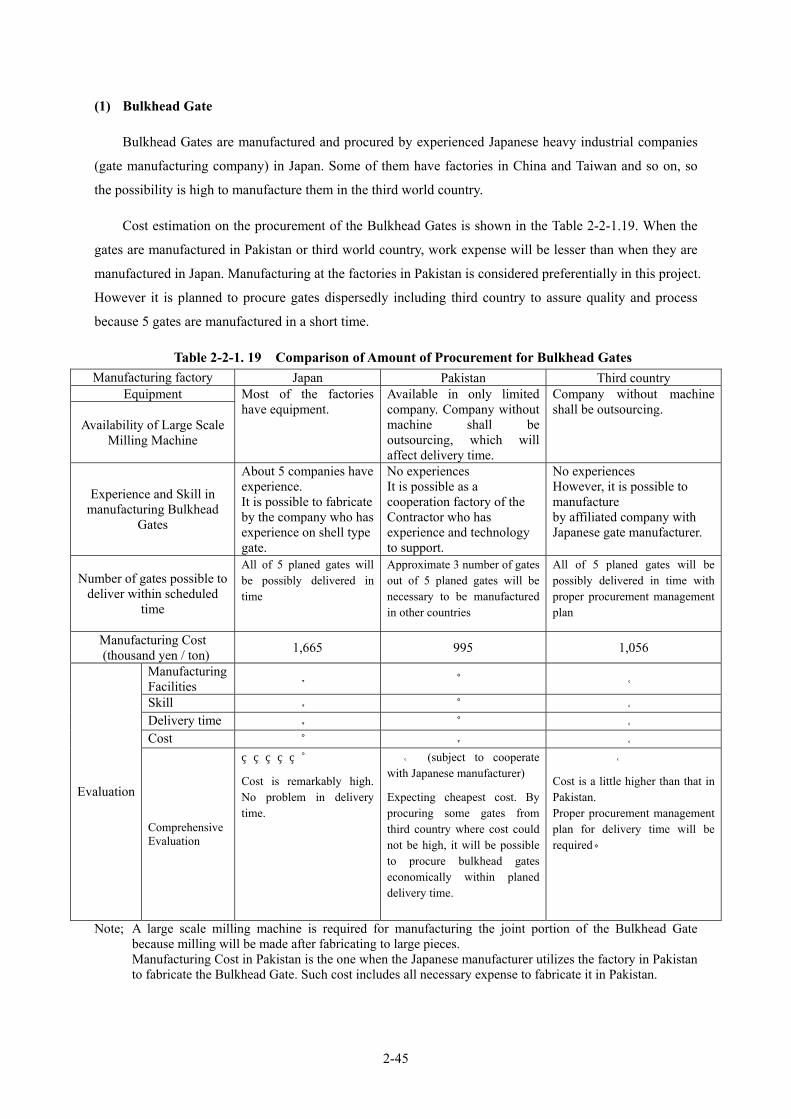
2-45
(1) Bulkhead Gate
Bulkhead Gates are manufactured and procured by experienced Japanese heavy industrial companies
(gate manufacturing company) in Japan. Some of them have factories in China and Taiwan and so on, so
the possibility is high to manufacture them in the third world country.
Cost estimation on the procurement of the Bulkhead Gates is shown in the Table 2-2-1.19. When the
gates are manufactured in Pakistan or third world country, work expense will be lesser than when they are
manufactured in Japan. Manufacturing at the factories in Pakistan is considered preferentially in this project.
However it is planned to procure gates dispersedly including third country to assure quality and process
because 5 gates are manufactured in a short time.
Table 2-2-1. 19 Comparison of Amount of Procurement for Bulkhead Gates Manufacturing factory Japan Pakistan Third country
Equipment
Availability of Large Scale Milling Machine
Most of the factories have equipment.
Available in only limited company. Company without machine shall be outsourcing, which will affect delivery time.
Company without machine shall be outsourcing.
Experience and Skill in manufacturing Bulkhead
Gates
About 5 companies have experience. It is possible to fabricate by the company who has experience on shell type gate.
No experiences It is possible as a cooperation factory of the Contractor who has experience and technology to support.
No experiences However, it is possible to manufacture by affiliated company with Japanese gate manufacturer.
Number of gates possible to deliver within scheduled
time
All of 5 planed gates will be possibly delivered in time
Approximate 3 number of gates out of 5 planed gates will be necessary to be manufactured in other countries
All of 5 planed gates will be possibly delivered in time with proper procurement management plan
Manufacturing Cost (thousand yen / ton) 1,665 995 1,056
Manufacturing Facilities ◎ △ ○
Skill ◎ △ ○ Delivery time ◎ △ ○ Cost △ ◎ ○
Evaluation
Comprehensive Evaluation
△
Cost is remarkably high. No problem in delivery time.
○ (subject to cooperate with Japanese manufacturer)
Expecting cheapest cost. By procuring some gates from third country where cost could not be high, it will be possible to procure bulkhead gates economically within planed delivery time.
○
Cost is a little higher than that in Pakistan. Proper procurement management plan for delivery time will be required。
Note; A large scale milling machine is required for manufacturing the joint portion of the Bulkhead Gate because milling will be made after fabricating to large pieces. Manufacturing Cost in Pakistan is the one when the Japanese manufacturer utilizes the factory in Pakistan to fabricate the Bulkhead Gate. Such cost includes all necessary expense to fabricate it in Pakistan.

2-46
(2) Under Sluice Gate / Weir Gate
While the existing gates have a steel truss structure, the new Under Sluice gates replaced will be a
plate girder structure. Fabrication and procurement of the gates with such structure will be possible to be
manufactured at the factories in Japan, Pakistan and the third world country that have experiences of
fabrication of plate girder type gates. Cost estimation of procurement of Under Sluice Gate and Weir Gate
are shown in table 2-2-1.20. When the gates are manufactured in Pakistan or third world country, work
expense may be lower than when they are manufactured in Japan. Manufacturing at the factories in
Pakistan is considered preferentially in this project.
Table 2-2-1. 20 Comparison of Amount of Procurement for Gates Manufacturing factory In Japan In Pakistan In Third world country
Equipment
Possession of Large Scale Milling Machine
Sufficient facilities available in most of Gate Maker factories
Available in limited steel manufacturing factories
Available in limited steel manufacturing factories
Experience and Skill in Manufacturing the
Truss Type Structure and Plate Guider Type Structure
Many Gate Makers have experience in manufacturing.
Limited steel manufacturing factories have experience. It will be possible for steel manufacturing factories to manufacture those gates as subcontractor under supervision of Japanese experienced Gate Makers
Limited steel manufacturing factories have experience. It will be possible for steel manufacturing factories who have affiliation to Japanese experienced Gate Makers or for steel manufacturing factories as subcontractor under supervision of Japanese experienced Gate Makers to manufacture those gates.
Delivery time:
Number of gates to be delivered within planned
schedule
All of 7 planned Under Sluice gates and 22 planned Weir gates will be possibly delivered in time
All of 7 planned Under Sluice gates will be possibly delivered in time. 8 numbers of gates out of 22 planned Weir gates will necessarily be manufactured in other countries
All of 7 planned Under Sluice gates and 22 planned Weir gates will be possibly delivered in time with proper procurement management plan.
Combined Under Sluice Gate and Weir Gate Manufacturing Cost (Thousand Yen/ton)
1,694 1,157 1,281
Manufacturing facilities ◎ △ ○
Skill ◎ ○ ○ Delivery time ◎ △ ○ Cost △ ◎ ○
Evaluation Comprehensive Evaluation
△ Cost is remarkably high. No problem in delivery time.
○ Expecting the cheapest cost. By procuring some gates from Third country where cost could be not high, it will be possible to procure those gates economically within the planned delivery time.
○ Cost is a little higher than in Pakistan. All of 7 planned Under Sluice gates and 22 planned Weir gates will be possibly delivered in time with proper procurement management plan.
However, some numbers of Weir Gate would be manufactured in third world country out of 22 gates when
the Under Sluice gates and a few bulkhead gates will be planned to manufacture at the factory in Pakistan
due to limited number of manufacturing facilities. Therefore, it is planned to procure gates dispersedly

2-47
including third country to assure quality and process because of necessity of delivery of gates in a short
period.
(3) Gate Hoist
Gate hoist must conform to strict standards on the strength and quality.
Particularly, when electrifying gate operation, torque will become bigger than current manual
operation. Therefore, higher technical specifications regarding strength of parts and accuracy on
manufacturing and assembling are required on this device.
Pakistani factory has no experience in manufacturing electrified gate hoist though they have
experiences with manual type. On manufacturing electrified devices, some works such as precise
workmanship, for example, butt seam welding of dram shell, gear engagement, centering of coupling and
so on are required. Therefore, it may be difficult for the factories in Pakistan to execute the work complying
with high accuracy technical standards, such as welding, machining, assembling and adjustment.
Accordingly, gate hoist is planned to be procured in Japan.
(4) Electrical Facilities
There are two major companies dealing with incoming and substation facilities in Pakistan. These two
(2) companies collectively occupy 80% share of the domestic market in Pakistan. Each company has about
40% of market share and the rest by other smaller companies. Therefore, these 2 major companies have
sufficient work experience in Pakistan.
Furthermore, considering O&M conditions in the future, it is desirable for this project to introduce
domestically produced equipment. Accordingly incoming and substation facilities are planned to be
procured in Pakistan.
However, local control panel for gate hoist is planned to be procured in Japan considering that both
two (2) major electric companies do not have the work experience in manufacturing this kind of panel. This
panel should be designed tolerable for the use in tropical area.
(5) Deck on Superstructure
It is planned that reinforcing components for superstructure and the components necessary for repair
work of deck on superstructure will be manufactured in the factories in Pakistan.
2-2-1-10 Procurement of Other Material and Equipment
(1) Tug boat, Boat and Truck crane for the Installation of Bulkhead Gate
The tugboat, the boat and the truck crane to be procured in this project will be used in construction
work, however, the delivery period is limited.

2-48
Equipment to be Procured Purpose of Procurement Time Limit of Procurement
Truck Crane: 50 ton class Assembly of Bulkhead Gate Before Oct, 2006 Tug Boat: 150ps, Boat : Live Load 1.2t Towing of Bulkhead Gate Before Jan, 2007
In Pakistan, there is only one dockyard in Karachi for building steel ships, which is run by government
and most of its products are mainly delivered to the state industries. There are some private companies
building glass fiber ships in Pakistan, and that deals with imported products from foreign countries.
Therefore, considering the limited period of delivery of ship, the above-mentioned boats are planned
to be procured in Japan.
(2) General Materials for Construction
It is possible for the contractor to procures the following construction materials, e.g. cement,
reinforcing bar, lumber, general building materials, lightweight steel product, electric wires, piping
materials and so on.
Most of them are planned to be transported from Lahore city to the project site. Coarse and fine
aggregates for concrete works are planned to be procured in D.G. Khan.
(3) Construction Machines
Most of general construction equipment such as backhoe, bulldozer, truck, crane can be procured (80
ton class crane is also available) in Pakistan. Local contractors have their own construction equipment. In
addition, there are companies that can lease these required / needed equipment.
However, procurement of construction equipment around Taunsa Barrage is difficult. Therefore, it is
proposed that the construction equipment be procured in Lahore city and transported to the project site.
Pontoon of unit float type will be used for repair work of under sluice gates, which is possible to
assemble and disassemble over a short period of time. It is proposed to procure this in Japan because it is
hard to procure in Pakistan and neighboring countries.
(4) Materials for the Temporary Works
Many of local construction companies use timbers as support materials and use boards for formworks
as well as steel scaffold. So, these temporary materials can be procured in Pakistan. Cofferdam in the
river is planned to be made with sandbags. Although usual sandbags are available in the market of Pakistan,
the large size bags that will be used in this project are planned to be procured in Japan.
In the procurement of steel sheet pile, there is neither market of the lease companies in Pakistan nor
neighboring Middle East countries. Procuring the leased materials from Japan is moderate in price than
purchasing in the neighboring countries of Pakistan. Therefore, it is proposed that the contractors procure
the leased steel sheet pile from Japan.

2-49
2-2-1-11 Construction Plan and Method
(1) Basic Construction Plan
Major components of this project consist of replacement of gate such as the under sluice gate, the end
beam of weir gate, the guide frame of sill beam and side beam, and the bulkhead gate will be set up at
upstream of the main gate as cofferdam.
The installation of bulkhead gate will be stopped from the middle of May to the middle of September
due to high velocity of river flow. On the other hand, the bulkhead gates have to be returned to stockyard at
the end of December due to annual closure period, in which rivers flow dramatically drop. Consequently,
taking these conditions into account, as it takes 3.5 months (February - Middle of May, Middle of
September – December) for the replacement period of one gate, basic construction plan shall be designed to
complete in the period.
The guide frame for bulkhead gate must be installed under dry condition during the annual closure
period. However as the period is limited to 30 days, number of work shifts must be increased in order to
complete the installation work within one month.
Existing equipment to be removed and installation equipment shall be carried by truck crane placed on
the attached road bridge. Construction schedule is formulated on the ground that daytime transportation
will be closed during construction period, except one hour. Taking into consideration Class AA (70 tons
army tank) loading, in case that weight of construction equipment exceeds 70 tons, pontoon shall be
required.
IPD requested the Japan’s Grant Aids for filling work of 100,000 m3 for bulkhead gate stockyard.
However, based on the principle of Japan’s Grant Aids, the filling works, which does not require high
technology, shall be carried out by recipient country. The filling work should be completed before October
2005, which is the beginning of the Project.
(2) Construction of Stockyard for Bulkhead Gate and Incline work
The incline work in the river requires cofferdam. The cofferdam is planned to combine embankment
and sheet piling and is designed to reduce the volume of filling soil as much as possible. Since concrete
volume of 1,600 m3 is necessary, it is planned to mix concrete at the site as there is no existing concrete
plant within the vicinity of Taunsa Barrage. Countermeasures against hot weather concrete placement
should be taken due to over 35 ℃ as a maximum temperature in the expected period of concrete works.
In addition, the construction of stockyard for bulkhead gate and incline work shall be completed
before the end of September 2006, which is the commencement of bulkhead gate assembly.

2-50
(3) Installation Work of Guide Frame for Bulkhead Gate
The guide frame for bulkhead gate must be
installed under dry condition during the annual
closure period (around 30 days from 1st January),
because water amount decreases and downstream
discharge can be stopped from Chashma Barrage
located in the upper area of Taunsa barrage
during this period. The Guide frame for bulkhead
gate is supplied as equipment project separately.
It is planned to install the first gate frame in
January 2007. Installation period is restricted
within one month, therefore 16 gates will be
installed in January 2007 and 13 gates in January
2008. Total construction number of gate to be
rehabilitated will decrease if the exchange works
of sill beam will be made combined with the
main gate rehabilitation works at the same time.
Therefore, exchange of sill beam of the Under
Sluice and Weir gates shall be done during the annual closure period simultaneous with the installation of
the gate frame
Amount of Guide Frame for Bulkhead Gate, Weir and Under Sluice Gates January 2007 January 2008
Bulkhead Gate 16 gates (18 piers) 13 gates (18 piers) Bulkhead Gate 16 gates 13 gates Weir Gate 13 gates 6 gates Under Sluice Gate - 7 gates
The guide frame and concrete materials shall be carried by 25 tons truck crane from the attached road
bridge due to insufficient time to construct the temporary access road in the river during annual closure
period.
(4) Rehabilitation of Under Sluice and Weir Gates
Rehabilitation period of main gate and guide frame is limited to 3.5 months each from middle of
September to December and from February to middle of May exclusive of annual closure period and
flooding period from middle of May to middle of September.
Besides, it is expected that the downstream water level of Taunsa Barrage during the construction of
the subsidiary weir, which is planned to be constructed at the downstream of Taunsa Barrage under the
project of Punjab Barrages Rehabilitation and Modernization from October 2005 for two years, is rather
higher than that after completion of the subsidiary weir as discussed in Section 2-2-1-12. In order to
Installation of the guideframe for bulkhead gate
Replace of the guide frame for main gate
Indus River is dry condition for only annual closureperiod in a year.

2-51
realize the proper condition for rehabilitation and to reduce the scale of the downstream cofferdam for
rehabilitation of gates, precedence will be given to rehabilitation of the Weir Gates due to higher elevation
of sill crest than that of the Under Sluice Gates. Accordingly, rehabilitation of the Weir Gates will mainly
be planned to implement in the year 2007 and that of the Under Sluice Gates will be in the year 2008 after
completion of the subsidiary weir.
There are two methods regarding to replacement of under sluice gate, such as pontoon method and
truck crane method. The pontoon method is the construction method by pontoon equipped with crane
from upstream of barrage and the truck crane method is by truck crane from the attached road bridge at
downstream.
Table 2-2-1. 21 Comparison of Construction Method for Replacement of Under Sluice Gate
Furthermore, other two cases of crane capacity mounting on pontoon are considered. The first case is
that the 50 tons truck crane procured for the project for assembling and disassembling of bulkhead gate will
be utilized for under sluice gate works. Another case is that 80 tons truck crane will be leased to reduce
the number of gate partition. Consequently based on the three cases study mentioned above, the pontoon
equipped with 80 tons truck crane is planned to be adopted. In addition, 25 tons truck crane is adopted for
hanging guide frame from attached road bridge.
(5) Rehabilitation of Gate Hoist
The gate hoist will be rehabilitated together with the gates. Considering that the replacement work of
gate hoist and the rehabilitation work of gate will be carried out at ups and downs simultaneously, safety
catcher will be installed for safety measures. 25 tons truck crane will be used for hanging guide frame of
gate from the attached road bridge. In addition, electric incoming and distribution line should be
completed before the commencement of gate rehabilitation because gates will be operated immediately
after rehabilitation. Final inspection and operation training will be executed at the time of completion of
Method Pontoon (80TTC) Pontoon (50TTC) Truck Crane Method
Execution Pontoon equipped with 80 tons crane
Pontoon equipped with 50 tons crane.
Truck equipped with 25tons crane and winch for pulling.
Number of Gate
Segment
9 segments (Maximum weight:8.0t)
15 segments (Maximum weight:4.5t)
25 segments (Maximum weight:3.5t)
76 days/one gate 4 gates/3.5 months
103 days/one gate 1 gate/3.5 months Construction period has to be extended
131 days/one gate Running over 3.5 months Required
period
○ × × No problem Negative impact such as twist
and shrinkage by welding due to large number of segments
Negative impact such as twist and shrinkage by welding due to large number of segments
Quality
○ × × Evaluation Good Not suitable Not suitable

2-52
gate hoist installation and gate rehabilitation.
(6) Rehabilitation of Upper Deck (Superstructure Deck)
Rehabilitation work of upper deck will be carried out simultaneously with rehabilitation work of the
gate hoist because partial reinforcement works of beam members of upper deck structure is required along
with replacement of gate hoist. Rehabilitation work of upper deck at the bay without gate rehabilitation will
also be carried out in flood season mainly in accordance with the progress of other gate rehabilitation. 25
tons truck crane on the attached road bridge will be used for removal and newly installation of upper deck,
hanging of reinforcing steel materials.
(7) Relocation of Telemeter Panel (DAU) (Pakistan side responsibility)
Gate position sensor (GPS), data acquisition unit (DAU) and other cables for data acquisition of gate
opening controlled under WAPDA might be obstacle for electrification of gate hoist and strengthening of
superstructure if left as is. Consequently these facilities of nine (9) units are planned to be placed at the
upper deck at the upstream of the barrage. Details are shown in Table 2-2-1.22.
Accordingly, relocation of telemeter panel and so forth will be relocated and its cost will be borne by
Pakistan side.
Table 2-2-1.22 List of Telemeter to be Relocated
2-2-1-12 Temporary Works
(1) Temporary Diversion Channel
The construction works on this grant aid project, such as 1) rehabilitation of weir gates, 2) replacement
of under sluice gates, 3) rehabilitation and electrification of gate hoist, 4) rehabilitation of deck on
superstructure, 5) installation of bulkhead gates, will be done in the Indus River. Therefore, temporary
diversion channel should be secured to flow the river discharge safely during implementation of works. The
Taunsa Barrage has 53 weir gates (60ft=18.3m span each) and 11 under sluice gates (60ft=18.3m span
Panel No. Location DAU 1 Gate No 5 of M.Garh canal ( for both canals T.P.Link & M.Garh) DAU 2 Gate No.2-3 center (pier) DAU 3 Gate No.9-10 center DAU 4 Gate No.17-18 center DAU 5 Gate No.25-26 center DAU 6 Gate No.33-34 center To be relocatedDAU 7 Gate No.41-42 center DAU 8 Gate No.49-50 center DAU 9 Gate No 57-58 center
DAU 10 Gate No.63-64 center DAU 11 Gate No.4 of D.G.Khan Canal

2-53
each). In order to flow the river discharge certainly, those gates will be utilized as temporary diversion
channel, provided that the temporary diversion channel should be more than one (1) gate away from the
actual gate to be rehabilitated.
① Construction Period and Design Discharge to be Diverted
The design discharge to be discharged by temporary diversion channel is estimated as the second to
the third – ranking of actual flood discharge during construction period which are recorded at the barrage
point in the last 10 years. If it is taken the probability analysis way to set the design discharge, the design
discharge is estimated as five years return period (refer to the criteria of design standard for Head-works,
MOAF Japan,).
The following three cases are considered for construction period under water of the River.
Case①; 9 months (from September,1 to May,31 of next year)
Case②; 8 months (from September,16 to May,15 of next year)
Case③; 7 months (from October,1 to Apri,30 of next year)
Table 2-2-1.23 The Actual River Discharge in Each Case (recorded in 1994-2003)
The construction period in the Indus River and the design discharge to be diverted are set up as
follows taking into consideration the flood discharge during the period and height of the temporary
cofferdam required at downstream of the barrage.
・The construction period; 8 months (Case②, from September,16 to May, 15 of next year)
・The design discharge ; Q=170,000 ft3/sec = 4,800 m3/sec
Remarks:
1) In case of Case ①, since it is supposed to be 350,000 ft3/sec of design discharge and 432.7 ft of
downstream water level, the height of temporary cofferdam at the downstream side of the barrage
should be high, about 8.0 ft. The period of nine (9) months is enough for implementation of
rehabilitation activities.
2) In case of Case ②, since it is supposed to be 170,000 ft3/sec of design discharge and 429.6 ft of
downstream water level, the height of temporary cofferdam should be relatively low, about 4.0 ft.
The period of eight (8) months is enough for implementation of rehabilitation activities.
3) In case of Case ③, since it is supposed to be 150,000 ft3/sec of design discharge and 429.2 ft of
Case Construction period Actual river discharge
Ranking
Case① 9 months (ft3/sec)
Case② 8 months (ft3/sec)
Case③ 7 months (ft3/sec)
The first 360,680 173,935 173,935
The second 352,908 168,264 153,746
The third 333,731 167,700 146,777

2-54
downstream water level, the height of temporary cofferdam should be low, about 3.0 ft. However,
the period of seven (7) months is too short for implementation of rehabilitation activities.
② The Number of Gate to be Utilized as Temporary Diversion Channel
The discharge per one gate and the required number of the gates to be operated to maintain upstream
water level of barrage at R.L.446.00 ft are as follows:
・ Water level at upstream: R.L. 446.00 ft = WL. 135.94 m
・ Water level at downstream: R.L. 429.60 ft = WL. 130.94 m
・ Elevation at gate sill: R.L. 428.00 ft = WL. 130.45 m
・ Gate span: 60 ft = 18.29 m
・ Water depth at upstream: H = 446.00 – 428.00 =18.00 ft = 5.49 m
・ Water depth at downstream: H = 429.60 – 428.00 = 1.60 ft = 0.49 m<2/3・H = 3.66m (complete overflow)
・ Unit discharge per gate: q = 3.09 * 60.00 * 18.003/2 = 14,200 ft3/sec/gate
・ The number of gate required: N = 170,000 / 14,200 = 12 gates
The design discharge during the construction period is diverted certainly when 12 units of gates are
fully opened. There is, however, a regulation concerning gate operation of the Taunsa Barrage which is
called as “The 2 ft rule”. The rule provides that the difference of gate opening range for two neighboring
gates should be for 2 ft or less. Therefore, the detailed plan of gate operation for rehabilitation works
should be prepared in conformity with this regulation.
(2) Temporary Coffer Dam at Downstream Side
① Water Level at Downstream of the Barrage for Gate Rehabilitation
The crest height of the subsidiary weir, which will be constructed at the downstream of the Taunsa
Barrage, is planned at R.L.424ft and the design discharge of flood expected during the construction is
170,000 ft3/sec (= 4,700 m3/sec). Under these conditions, the river water level at downstream of the
Barrage estimated are as follows:
・ Before construction of the subsidiary weir: D/S WL. 427.50 ft = D/S WL. 130.30 m
・ Under construction of the subsidiary weir: D/S WL. 433.90 ft = D/S WL. 132.25 m
・ After construction of the subsidiary weir: D/S WL. 429.60 ft = D/S WL. 130.94 m
As mentioned above, the river water level at downstream of the Taunsa Barrage under construction of
the subsidiary weir is supposed to be 433.90 ft. Therefore, the months where small scale floods occur
(April, May, and September) should be excepted from the rehabilitation work period.
Accordingly, the river water level at the downstream of the Taunsa Barrage under rehabilitation is
regarded at D/S WL429.60 ft after the construction of the subsidiary weir.
② Height and Structure of the Cofferdam at Downstream

2-55
1) The crest elevation of the cofferdam
The crest elevation of the cofferdam is to be R.L. 432.00ft (= EL. 131.67m) added some free board to
the river water level at downstream of D/S. WL. 429.60ft (= D/S WL. 130.94m).
・ The water level at downstream of the Barrage D/S WL. 429.60ft = D/S WL. 130.94m ・ The crest elevation of the cofferdam R.L. 432.00ft = EL. 131.67m ・ The elevation of existing inclined apron Weir R.L. 425.00ft = EL. 129.50m
U. sluice R.L. 422.00ft = EL. 128.60m ・ The height of the cofferdam Weir 7.00 ft = 2.13 m
U. sluice 10.00 ft = 3.05 m 2) The structure of the cofferdam
Since the cofferdam will be constructed on the existing inclined apron due to the height of the
cofferdam which is relatively low, (2.13m to 3.05m), large size sandbag should be utilized so as to make
construction of the cofferdam easy and well sealed (waterproof).
(3) Temporary Construction Road and Temporary Bridge
① Temporary Construction Road
・ It is not necessary to construct temporary road due to availability of trunk road which is running
through the project site from the Indus highway. Construction equipment can pass through the highway
as the height of power line crossing the road is beyond 4.5mand based on international standard.
・ The corner, which is to be connected to the stockyard for bulkhead gate at left bank of upstream, is
passable to trailers by utilizing the parking space.
・ The allowable designed truck load for the existing bridge of the Taunsa Barrage is 12 tons per axle. The
feasibility study conducted by the Government of Punjab reports that the existing bridge is safe for
construction transportation even by “Class AA (the design load for bridge considered 70 tons as heavy
tank)”.
・ The feasibility study conducted by the Government of Punjab also reports that the existing bridges,
which are located at RD 7,500, at the intake of Muzaffargah canal and T.P. Link Canal , are safety
based on “Class AA (the design load for bridge considered 70 tons as heavy tank)”.
② Temporary Bridge
・ It is unnecessary to construct the temporary bridge for the gates rehabilitation works because these
works can be undertaken at the gates site from the existing bridge or by using the pontoon approaching
from the upstream side.
(4) Temporary Jetty
・ The temporary jetty for shipment of construction material should be provided because the construction

2-56
works are supposed to be done by utilizing the pontoon accessing from upstream of the Taunsa
Barrage.
・ The location of the temporary jetty should be decided through the comparative study between locations
at upstream of both right and left banks if the temporary stockyard for construction material and goods
is planned at right bank of the Barrage.
(5) Electric Power Supply Facilities for Construction
① Undertaking of Construction and Installation
・ Pakistan side responsibility is provision of outside wiring of electric facilities, while Japan side
responsibility are the receiving lines, receiving panel, and transformer as well as power for
construction.
・ Regarding responsibility of temporary power supply for construction, it will be done as the same as
that of power for permanent electric facilities.
・ The point which allots a portion of these kind works to each side should be 11 kV high voltage power
line in the site of Taunsa Barrage O&M office.
② Comparison between Commercial Power Supply and Generator as the Power for Construction
Several alternatives are proposed to ensure the huge capacity of power supply for under sluice gate
rehabilitation work as follows:
・ Case①; All the power supply for construction is to depend on commercial power supply as temporary.
・ Case②; The electric power supply facility to be provided under the Project will supply the power for
construction. The shortage of power depends on the commercial power as temporary.
・ Case③; Taking account the frequent occurrence of power failure and the site condition, there are two
ways of supplying power system for the project. The power generator is proposed to be used for
rehabilitation works of under sluice gate because of the short period of construction with large capacity
of power requirement, while weir gate rehabilitation works is to depend on commercial power supply
as temporary because of dispersed spots with small consumption of power..
・ Case④; Taking account of the occurrence of power failure, the site condition, and responsibility of
Pakistan side, all the temporary power supply is to be received from temporary generator.
The cases mentioned above should be studied taking every factor into consideration.
(6) General Temporary Facilities
・ For the site office (approximately 3 container house) and accommodation of the contractor, and rest
room of labor are planned as general temporary facility.
2-57
・ The yard for general temporary facilities should be approximately 1,200m2 (=20m x 60m).
・ With regard to the electricity, it is planned to receive the power from existing 11KV high voltage power
line that is running near the Taunsa Barrage. There occurs about 10 times of power failure a month. It is
needed to prepare stand-by power generator for major facilities.
・ Regarding water supply, there is no domestic water supply facility but underground water is utilized in
the project area. The Indus River cultivates the underground water in the area. It is, therefore, planned
to utilize the underground water through the well.
・ With respect to communication, international line as well as domestic one can be secured. Furthermore,
the network of mobile phone is available in the area of Taunsa.
(7) Temporary Yard for Gate Rehabilitation/Construction Work
① Temporary Yard for Construction Materials and Goods
・ The temporary stockyard (1,500m2) to keep construction materials and goods is planned to be located
at right bank at downstream of the Taunsa Barrage.
・ Ownership of the land mentioned above belongs to the Government. Therefore, it will be used without
compensation during construction and rehabilitation works.
② Temporary Yard for General Facilities
・ The temporary yard (2,700m2) for general facilities such as the site office of contractors is planned to
be located at left bank of T.P. Link Canal which is placed at left bank at upstream of the Taunsa
Barrage.
・ The land mentioned above belongs to the Government. Therefore, it will be used without compensation
during construction and rehabilitation works.
2-2-1-13 Operation and Maintenance of Facilities
Operation and maintenance policy is shown as follows.
1) The Taunsa Barrage Division, Irrigation and Power Department, Punjab Province will be responsible for operation and maintenance of Taunsa barrage rehabilitated as with present condition.
2) The maintenance method of the facilities will basically follow the existing arrangement at the Taunsa barrage.
3) Technical transfer of operation and maintenance of the Bulkhead gate, which will be newly introduced, is planned through “On the Job Training (OJT)” to Pakistan side.

2-58
2-2-1-14 Ability on Operation and Maintenance of Executing Agency
(1) Ability on Operation and Maintenance (O/M) of Executing Agency
At present, the Taunsa barrage is operated and maintained by the Taunsa Barrage Division(TBD)with
a total staff of 380. They have sufficient O/M experience about 50 years, and there is no identified
constraint in their capacity to undertake O/M of the barrage with the existing staff.
(2) Number of Gate Operator and Electrician
Since the project executed under Grant Aid is mainly concerned with the rehabilitation of mechanical
facilities, no additional organization is required for O/M. However, the number of gate operator will be
reduced because gates will then be operated by the electricity instead of existing manual operation.
At present, the Taunsa barrage gate is operated by 35 members (Regulation Beldar) with three shifts of
groups of 10 to 12 members and which is increased from time to time during the flood season.
29 units of gate will be electrified under the Grant Aid Project while the remaining gates will be
electrified under the“Punjab Barrages Rehabilitation and Modernization Project”. Accordingly, it is
expected that the gates will be maintained and operated by 15 members (three shifts of 5 persons), which is
almost half of existing number based on the survey results of the other barrages.
Besides, the number of an electrical engineer and technician will not be increased because it would be
possible to have shifts or hold the post with other section.
2-2-1-15 Environmental and Social Considerations
This grant aid project consists mainly of the rehabilitation of the gates, and no environmental and
social impacts are expected. At the same time, “Punjab Barrages Rehabilitation and Modernization Project”
by the Punjab Province includes the large scale of civil works, and bad environmental effects are concerned.
However, the procedure of environmental impact assessment by the IPD has been preceded combining both
the above projects and the Environment Protection Agency (EPA) approved for construction phase of
Taunsa Barrage rehabilitation on September 6, 2004.
Considering the above condition, environmental and social consideration will be progressed based on
the following policy:
- Based on the “Pakistan Environment Protection Law 1997”, the IPD should follow the procedure and
policy of environment impact assessment (EIA) in the implementation of the project.
- Social consideration will be secured such as information of road closure of Taunsa Barrage to the
neighboring people completely that the bridge is going to close about 8.00-12.00 in the morning and
13.00-17.00 in the afternoon during the construction except the flood season together with information
of the detour road, using mass media or a signboard.

2-59
2-2-2 Basic Plan
2-2-2-1 Rehabilitation of Under Sluice Gates and Weir Gates
(1) Outline
As the locker assembly mechanism is the main cause of the current problems, this mechanism will be
completely rehabilitated in all the Under Sluice gates and Weir gates.
(2) Under Sluice Gates
① Type of Gate Leaf
The existing double gate leaf of under sluice gates will be modified to single gate leaf gates because of
the following reasons.
• Water leak between the gate leaf will damage the watertight structure between the upper and lower gate
leaves. This damage to the watertight structure will increase the amount of leakage while the vibration of
the gate will adversely affect the gate leaf, wire rope and hoist, etc.
• Discharge through the gate leaf in the case of double gate leaf is unnecessary for under sluice operation
at the Taunsa Barrage.
• Double gate leaf will require synchronised operation of the upper gate leaf and lower gate leaf for gate
opening or closing operation, making such operation complicated.
② Locker Assembly Structure
Figure 2- 2-2.1 Remodelling of Locker Assembly
Gate Leaf
Roller Train
Locker Assembly
[Existing Structure]
[Post-Rehabilitation Structure]
Locker Assembly
Gate Leaf
Roller Train
[Proposed]

2-60
In view of the current problems, the following modifications will be made to the locker assembly
structure.
• The fixing point of the locker assembly will be changed from the gate leaf to the gate guide.
• The locker assembly brackets which are currently mounted horizontally at several points will be changed
to vertical continual brackets.
③ Materials to be used
The materials to be used for each member will be selected based on relevant provisions of the
Technical Standards for Gates and Penstocks.
Table 2-2-2.1 shows the materials to be used for each member. The selection of the materials for the
roller, which is closely related to the current problems, is described below. The current problems with the
roller originated from the fact that the roller hardness is higher than the groove hardness. By selecting the
combination described below in accordance with the said Technical Standards, the roller hardness will be
lower than the groove hardness.
Table 2-2-2.1 List of Materials to be used (Under Sluice Gates) Parts Spec (JIS) Symbol Notes
Skin Plate Rolled steels for welded structure JIS G 3106 SM490 ASTM A633 Gr.C
Girder Rolled steels for welded structure JIS G 3106 SM490 ASTM A633 Gr.C
Roller Rolled steels for welded structure JIS G 3106 SM400 ASTM A283 Gr.D
Inter Mediate Girder Rolled steels for welded structure JIS G 3106 SM400 ASTM A283 Gr.D
Roller High tensile strength carbon steel castings and low alloy steel castings for structural purposes JIS G 5111
SCMn3B ASTM A148M-93b 105-85
Roller Pin Stainless steel bars JIS G 4303 SUS304 ASTM A240M-01
Type304
Gate leaf
Truck Plate Stainless steel bars JIS G 4303
SUS304N2
ASTM A276-98a XM-21
Rocker Assembly Stainless steel bars JIS G 4303
SUS304N2
SUS304
ASTM A240M-01 Type304 ASTM A276-98a XM-21
Sill Plate Stainless steel bars JIS G 4303 SUS304 ASTM A240M-01
Type304 Groove
Sill beam Rolled Steel for General StructureJIS G 3101 SS400 ASTM A36
Drum gear Chromium Molybdenum Steels JIS G 4105 SCM440 AISI ISS209
Pinion gear Chromium Molybdenum Steels JIS G 4105 SCM440 AISI ISS209
Drum Rolled steels for welded structure JIS G 3106 SM490C ASTM 633 Gr.C
Pin Carbon Steels for Machine Structural Use JIS G 4051
S45C AISI ISS209
Hoist
Bed flame Rolled steels for welded structure JIS G 3106 SM400 ASTM A283 Gr.D

2-61
④ Design Stress
Table 2-2-2.2 lists the design stress and the allowable stress for the main members of the under sluice
gate.
Table 2-2-2.2 List of Stresses for Main Members of Under Sluice Gate
Inspection Item Dimensions Type of Stress
Generated Stress
(N/mm2)
Allowable Stress
(N/mm2) Material
Bearing 143 158 SM490 Girder BH2200 x 300 x 19/22 Shearing 29 91 SM490
Main Girder
Maximum Deflection ( Girder) Deflection 1/825 1/600 SM490 Skin Plate (section of maximum stress: section)
Section: PL10 Bending 125 158 SM490
Main Roller φ150 x 130B Roller Contact 717 754 SCMn3B Guide Frame Contact 910 1,029 SUS304N2
The generated stress corresponds to about 80% of the allowable stress. The gate leaf deflection is the
most severe among design conditions with a generated deflection of 1/829 against an allowable deflection
of 1/600.
Table 2-2-2.3 shows the under sluice gate specifications.
Table 2-2-2.3 Under Sluice Gate Specifications Type Steel plate girder roller gate Quantity 7 Clear Span x Gate leaf Height (B) 60.00 ft x (H) 23.00 ft [(B) 18.29 m x (H) 7.01 m]
Upstream Side 23.00 ft (7.01 m) Design Water Depth Downstream Side 0.00 ft (0.00 m) Upstream Side 23.00 ft (7.01 m) Opening
Operation Downstream Side 0.00 ft (0.00 m) Upstream Side 23.00 ft (7.01 m) Operating Water Depth
Closing Operation Downstream Side 0.00 ft (0.00 m) Design Sedimentation Height 6.00 ft (1.83 m) Sill Height RL. 425.00 ft (EL. 129.54 m) Water Tightness Method Rubber sealing on three front sides hoist One motor, two drums, wire rope winch type Operating Method Operated from the motor side Operating Speed 1.0 ft/min (0.3 m/min) Lifting Height 31.00 ft (9.45 m)
(3) Weir Gates
① Outline
The rehabilitation of the weir gates consists of the following two types of work.
• Improvement of the current problems (roller)
• Heightening of the gate leaf height by one foot
With regards to the planned improvement of the current problems, the present structure will be kept
for the main sections of the leaf based on the study results. However, the severely damaged end girders will
be remodelled in consideration of their vital relation to the roller.

2-62
② Structure of Roller
As in the case of the under sluice gates, the roller will have a structure where the locker assembly is
mounted to the groove side.
③ Materials to be used
As in the case of the under sluice gates, different materials will be combined so that the roller hardness
is lower than the groove hardness.
The materials to be used for the main structural members are shown in Table 2-2-2.4.
Table 2-2-2.4 List of Materials to be used (Weir Gates)
Parts Spec (JIS) Symbol Notes
Skin plate Rolled steels for welded structure JIS G 3106 SM400 ASTM A633 Gr.C
Side beam Rolled steels for welded structure JIS G 3106 SM400 ASTM A283 Gr.D
Roller
High tensile strength carbon steel castings and low alloy steel castings for structural purposes JIS G 5111
SCMn3B ASTM A148M-93b 105-85
Roller Pin Stainless steel bars JIS G 4303 SUS304 ASTM A240M-01
Type304
Gate leaf
Track Plate Stainless steel bars JIS G 4303
SUS304N2
ASTM A276-98a XM-21
Rocker Assembly Stainless steel bars JIS G 4303
SUS304N2
SUS304
ASTM A240M-01 Type304 ASTM A276-98a XM-21
Sill Plate Stainless steel bars JIS G 4303 SUS304 ASTM A240M-01
Type304
Groove
Sill beam Rolled Steel for General StructureJIS G 3101 SS400 ASTM A36
Drum gear Chromium Molybdenum Steels JIS G 4105 SCM440 AISI ISS209
Pinion gear Chromium Molybdenum Steels JIS G 4105 SCM440 AISI ISS209
Drum Rolled steels for welded structure JIS G 3106 SM490C ASTM 633 Gr.C
Pin Carbon Steels for Machine Structural Use JIS G 4051
S45C AISI ISS209
Hoist
Bed flame Rolled steels for welded structure JIS G 3106 SM400 ASTM A283 Gr.D
④ Design Stress
Table 2-2-2.5 lists the design stresses and allowable stresses for the main members of weir gate.

2-63
Table 2-2-2.5 List of Stresses for Main Members of Weir Gate
Inspection Item Dimensions Type of Stress Generated Stress (N/mm2)
Allowable Stress (N/mm2) Material
Bending 30 118 End Girder BH400 x 150 x 12/22 Shearing 21 68 SM400
Main Roller (13) φ150 x 130B Roller Contact 746 754 SCMn3B Guide Frame Contact 946 1,029 SUS304N2
As the dimensions of the girders and other components of the weir gate end structure are determined
in conformity with that of the existing gate leaf, there is much more leeway in terms of the unit stress than
in the case of under sluice gate.
Table 2-2-2.6 shows the weir gate specifications.
Table 2-2-2.6 Weir Gate Specifications Type Steel Truss Roller Gate Quantity 7 Clear Span x Gate leaf Height (B) 60.00 ft x (H) 20.00 ft [(B) 18.29 m x (H) 6.10 m]
Upstream Side 20.00 ft (6.10 m) Design Water Depth Downstream Side 0.00 ft (0.00 m) Upstream Side 20.00 ft (6.10 m) Opening
Operation Downstream Side 0.00 ft (0.00 m) Upstream Side 20.00 ft (6.10 m) Operating Water Depth
Closing Operation Downstream Side 0.00 ft (0.00 m) Design Sedimentation Height 3.00 ft (0.91 m) Sill Height RL. 428.00 ft (EL. 130.45 m) Water Tightness Method Rubber sealing on three front sides Hoist One motor, two drums, wire rope winch type Operating Method Operated from the motor side Operating Speed 1.0 ft/min (0.3 m/min) Lifting Height 29.00 ft (8.84 m)
2-2-2-2 Gate Hoist
(1) Outline
The following two modifications will be made to the hoist.
• Electrification (including renewal of the drum and drum gear, etc.)
• Change of the location (change to a single floor configuration)
(2) Electrification
The hoist of both the under sluice gates and weir gates will be electrified.
(3) Change to Single Floor Configuration
An analysis of problems of the existing hoist indicates that many problems occur with the structural
members and components, etc. when the power and drum unit are located on different floors (in this present
system located at the upper and lower floors respectively). To rectify the identified problems and to

2-64
improve the operational control of this apparatus, it is planned to locate the power and drum unit on the
same floor under the Project.
F
i
g
u
r
e
.
2
F
Figure 2-2-2.2 Configuration of Hoist
2-2-2-3 Electrification of Gate Hoist
(1) Required Motor Output for Hoist
The results of examination of the required motor output for hoist are described below.
① Operating Load
Table 2-2-2.7 shows the operating load, taking the dead weight of the gate leaf and the roller friction,
etc. into consideration for calculation purposes.
Table 2-2-2.7 Operating Load of Under Sluice Gate
Item Opening Closing Downward Force When Opening
Dead Weight of Gate Leaf 520 520 520 Friction Resistance of Roller 62 62 62 Friction Resistance Between Sealing Rubber and Metal 27 27 27 Friction Resistance Between Sediment and Metal 49 0 49 Down Pull Force 0 0 0 Counterweight 395 395 0 Total 263 36 658
The operating load is set at 265 kN based on an operating load of 263 kN at the time of opening
operation.
② Required Motor Output (Pm)
W ・ V Pm = 60・η
Where, W : operating load = 265kN
Drum Unit Power Unit

2-65
V : operating speed = 0.30 m/min η : general efficiency at start-up = 0.645 265×0.30 Pm = = 2 . 0 2 k W 60×0.645
The rated output of 2.2 kW which is the nearest rated output above 2.02 kW will be adopted.
③ Specifications of Motor to be Used
Type : totally enclosed fan-cooled outdoor motor Output : continuous rating of 2.2 kW Poles : 6P; 50 Hz Rated Speed : 940 rpm
Similar calculation for the weir gates produced an operating load of 165 kN and a motor output of 1.5 kW.
Table 2-2-2.8 shows the hoist specifications.
Table 2-2-2.8 Hoist Specifications Under Sluice Gate Weir Gate
Type One motor, two drum, electric wire rope winch type
One motor, two drum, electric wire rope winch type
Number of Installations 7 units (for 7 gates) 22 units (for 22 gates) Operating Load 265 kN 165 kN Operating Speed 1.0 ft/min (0.30 m/min) 1.0 ft/min (0.30 m/min) Lifting Height 32.00 ft (9.75 m) 29.00 ft (8.84 m) Motor 2.2 kW 6P continuous rating 1.5 kW 6P continuous rating Wire Rope φ60 IWRC 6 x WS (36) Type B φ56 IWRC 6 x WS (36) Special type Operating Method Operated from the local panel Operated from the local panel Power Source 3 phase AC, 50 Hz, 400 V 3 phase AC, 50 Hz, 400 V
2-2-2-4 Rehabilitation of Upper Deck (Superstructure)
The following modifications will be undertaken to the upper deck (superstructure).
• Change of the deck plates (from wooden plates to grating) • Reinforcement of the structural members following electrification of the hoist
The deck plates will be changed from the current wooden plates to grating. In consideration of the
load of the hoist which will be remodelled, the crowd load and wind load, the suitability of the steel frame
structure of the existing superstructure was examined. It was concluded that the structure for the under
sluice gates will require reinforcement at both ends where the drum unit will be installed.
As the size of the members forming the steel frame structure of the superstructure for the weir gates is
much smaller than that of the under sluice gates, reinforcement will be required at both ends where the
drum unit will be installed and also at the central section where the power unit will be installed. This
reinforcement will be conducted by welding flat steel (PL 50 x 6) to the existing unequal angle steel (L 76
x 50 x 10). The reinforcing sections for the structural members are shown in Figure 2-2-2.3.

2-66
Fix.
Mov.
σc = -68 N/mm2 < σca = 86 N/mm2
軸圧縮力最大箇所 応力度
OK
σc = -85 N/mm2 > σca = 74 N/mm2
補強前 軸圧縮力最大箇所 応力度
OUT
補強前
補強後
2 - PL 50 x 6 (SM400)
補強材断面
補強材
梁 鉛直材
Under Sluice Gate
Maximum stress of Axis Compression OUTmm/N74mm/N76 2
ca2
c =σ>−=σ
Maximum Stress of Axis Compression OKmm/N86mm/N60 2
ca2
c =σ<−=σ
Vertical beam
Before Reinforcing
After Reinforcing Section of Reinforcement Material
2-PL50x6 (SM400)
Reinforcement Material
FLOW
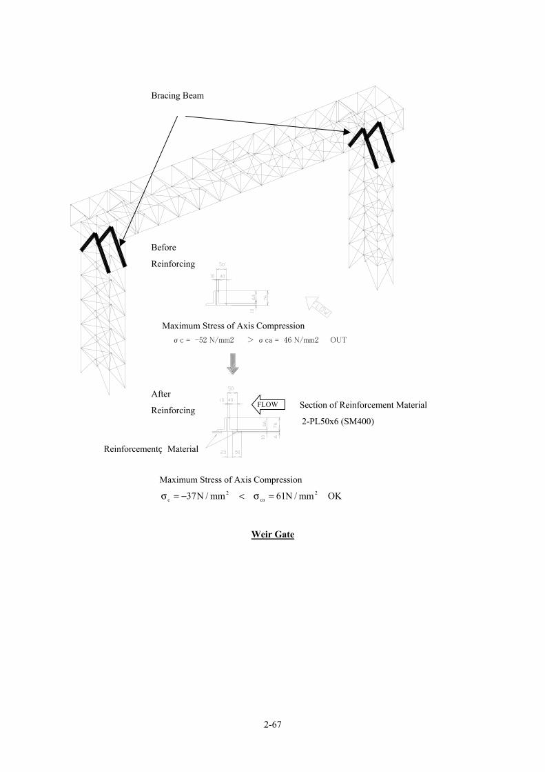
2-67
σc = -41 N/mm2 < σca = 61 N/mm2
軸圧縮力最大箇所 応力度
OK
σc = -52 N/mm2 > σca = 46 N/mm2
補強前 軸圧縮力最大箇所 応力度
OUT
補強前
補強後
2 - PL 50 x 6 (SM400)
補強材断面
補強材
Weir Gate
Before
Reinforcing
After
Reinforcing Section of Reinforcement Material
2-PL50x6 (SM400)
Reinforcement Material
FLOW
Bracing Beam
Maximum Stress of Axis Compression
OKmm/N61mm/N37 2ca
2c =σ<−=σ
Maximum Stress of Axis Compression

2-68
σc = -79 N/mm2 < σca = 84 N/mm2
軸圧縮力最大箇所 応力度
OK
σc = -94 N/mm2 > σca = 75 N/mm2
補強前 軸圧縮力最大箇所 応力度
OUT
補強前
補強後
1 - PL 50 x 9 (SM400)
補強材断面
補強材
梁外側 梁中側 (形状保持リブ 1mピッチ)
Weir Gate
Figure 2-2-2.3 Reinforcing Sections for Superstructure
Before
Reinforcing
After
Reinforcing
Section of Reinforcement Material
2-PL50x9 (SM400) Reinforcement Material
Maximum stress of Axis Compression
OUTmm/N75mm/N94 2ca
2c =σ>−=σ
Maximum Stress of Axis Compression
OKmm/N84mm/N79 2ca
2c =σ<−=σ
Outside Inside ← → Rib(Pitch 1m)
Upper Horizontal Beams

2-69
2-2-2-5 Bulkhead Gates
The bulkhead gate system has been selected based on the results of a comparative analysis involving
other systems, including the temporary coffering system. Table 2-2-2.9 shows the bulkhead gate
specifications.
Table 2-2-2.9 Bulkhead Gate Specifications Gate Type Steel floating gate Dimensions Clear span 18.29 m x gate leaf height 7.70 m Number of Gates 5 units Design Maximum Water Depth 7.70 m Sill Elevation RL 423.00 ft [Under Sluice Gate] RL 426.00 ft [Weir Gate] Design Water Level RL 448.26 ft Storage Method Winching using a platform car and inclined plane Water Tightness Method Rubber sealing on three sides at the back
Each gate leaf of the bulkhead gate will be divisible by three (3) both vertically and horizontally so
that it is actually composed of nine (9) blocks to allow its use for other barrages and these blocks will be
joined with bolts.
Table 2-2-2.10 shows the stress calculation results for the main members of the bulkhead gate. The
gate depth is set at 3.00 m to ensure its stability when the gate is floating upright. The cross-section of the
main girder is determined based on the minimum member thickness of the shell structure.
Table 2-2-2.10 Stresses for Main Members of Bulkhead Gate
Inspection Item Dimensions Type of StressGenerated
Stress (N/mm2)
Allowable Stress
(N/mm2) Material
Bending 15 177 SS400 Shearing 12 102 SS400 Upper
Block Box shaped cross-section 2,500 x 3,000 x 10 Composite with
skin plate 47 195 SS400
Bending 43 177 SS400 Shearing 24 102 SS400 Middle
Block Box shaped cross-section 2,200 x 3,000 x 10 Composite with
skin plate 113 195 SS400
Bending 92 177 SS400 Shearing 67 102 SS400 Lower
Block Box shaped cross-section 2,500 x 3,000 x 10 Composite with
skin plate 186 195 SS400
Main Girder
Maximum Deflection Deflection 1/1,535 < allowable deflection 1/600

2-70
RL678.0
NWL692.0
FWL698.0
(1)Jinnah barrage
RL477.5
NWL490.0
FWL492.0
(2)Trimmu barrage
Figure 2-2-2.4 Installation Plan for Other Barrages
Using two blocks
(divided tree blocks)
Impossible to
install
(divided two
blocks)
Using two blocks
(divided tree blocks)
Impossible to
install
(divided two
blocks)

2-71
2-2-2-6 Tug Boats, Boats, Crane and Spare Parts
Table 2-2-2.11 shows the specifications for tug boats and others which are required for bulkhead gate
operation.
Table 2-2-2.11 Specifications for Auxiliary Equipment for Bulkhead Gate Operation Item Purpose of Use Specifications Remarks
Tug Boat Towing of bulkhead gate 150 PS x 2
Boat Transportation of bulkhead gate installation equipment
Boat capable of carrying 1.2 tons x 3 units
Main Crane Assembly and disassembly of bulkhead gate 50 ton truck crane x 1 unit
Spare Parts Repair and maintenance Bolts, nuts, packing, paint, crane, tug boat maintenance tools and others
See 2.2.10 for details
The provision of spare parts needed in the three (3) years period, i.e. two (2) years for the on-site work
and one (1) year for operation and maintenance period, will be considered.
2-2-2-7 Bulkhead Gate Stockyard
(1) Layout of Bulkhead Gate Stockyard
① Location of Bulkhead Gate Stockyard
Regarding the stockyard of bulkhead gates, two places of stockyard storing 3 gates each at both right
and left banks have been proposed in the “Feasibility Study on Taunsa Barrage Irrigation System
Rehabilitation” report prepared by JICA Study Team in August 1998. However the Government of
Pakistan at the request stage of JICA Grant Aid Programme for this project revised the above plan to lump
stock plan with 5 gates at the left bank considering their storages and O&M.
Location of bulkhead gate stockyard was decided at 450 m upstream from the Taunsa Barrage, and the
reasons for its selection are as follows.
• The water rout is near the left bank side, and sedimentation on the inclination is considered to be a
few.
• O&M Office of the Taunsa Barrage is located at the left bank side. This is convenient as far as
storage, management, and the O&M works for the bulkhead gates is concerned.
• Left bank side is in the extents of erosion areas, and it is easy to secure the necessary draft depth
for towing the bulkhead gates.
② Scale of Bulkhead Gate Stockyard
The scale of the stockyard is as follows.
• Length of stockyard: 160.0 m

2-72
(Inclination length: 58.4 m + stockyard length: 81.6 m + width of passage: 10.0 m+ width of dike
road: 10.0 m)
• Width of Stockyard: 90.0 m
(Width of dike road: 10.0 m x 2 rows + width of passage: 10.0m x 2 rows + gate loading space:
13.0 m+ width of stockyard: 27.0 m+ width of working space: 10.0 m)
• Scale of stockyard: 14,400 m2
(Length: about 160 m x width: about 90 x embankment height: 6.0 m)
A A
33.00' [10,060] 33.00'
[10,060] 267.40'
[81,500]
525.00'
[160,020]
33.00' [10,060] 158.60'
[48,340]
230.00'
[70,100]197.00'
[60,050]
48.00'
[14,630]
[10,0
60]
[10,0
60]
[10,0
60]
33.0
0' 33
.00'
[89,9
20]
295.0
0'
[26,8
20]
88.0
0'
33.0
0'
[12,8
00]
42.0
0' [1
0,0
60] [10,
060]
33.0
0' 3
3.0
0'
50T TRUCK CRANE
WINCH STAGE
CART
PLAN
Figure 2-2-2.5 Layout of Bulkhead Gate Stockyard

2-73
(2) Equipment Plan
① Inclination
1) Slope of Inclination
As to the slope of inclination facilities for the bulkhead gate stockyard, careful study would be needed because when the gentle slope is applied for the inclination, embankment volumes of the bank would be increased. Also when the steep slope is selected, the winch capacity would accordingly increase resulting in the increase of the project costs, especially equipment costs. Also there should be more concern on safety aspects.
a) Examination Conditions
i) There is fear of damage to the main body of the gate or sinking to the riverbed caused by the influence of sudden discharge by the gate operation mistakes or the collision of driftwood and the ship and etc. when the bulkhead gate is moored in the river through the night due to unfinished installation work of the bulkhead within one day. If the bulkhead gate gets damages, no works can be advanced. Therefore, it is very essential to complete the works from launching to installation at the prescribed place within one day to avoid damages to the bulkhead gate.
ii) The bulkhead gate installation work is examined assuming that the works would be completed within one day. Working hours considered is 8 hrs.
iii) The work procedures and the time required for the installation of the bulkhead gate are as follows.
① Launching from inclination equipment ② Towing 0.5hr ③ Bulkhead gate upright work preparation 1.0hr ④ Bulkhead gate careening and upright work 1.5hr ⑤ Bulkhead subsidence work 1.0hr ⑥ Prescribed, positional horizontal movement (attraction by rope) 0.5hr ⑦ Bulkhead gate subsidence minute adjustment work and fixation 1.0hr
Total 5.5hr
iv) The time required for launching work from the inclination equipment is set as 2.5 hrs from the above-mentioned time.
v) There are regulations of making the inclination in less than 45° (1:1) in case of dealing with light equipment such as motorboats. However, because of the heavy weight of the inclination facilities (more than 100 tons), incidents such as running into foreign materials on rails of the inclination, or influence of slight impacts caused by water flow and driftwood, it may cause the bulkhead gates to slip and fall-down from the truck in case of steep slope. It is therefore difficult to adopt steep inclination considering high risk and extent of possible damage that may occur.
vi) The inclination is set to about 10° in this examination based on comparative study of the following three cases of inclination alternative of 1/15, 1/10, and 1/5.

2-74
b) Examination Results
Result of the examination shows that (refer to Table 2-2-2.12), in case of Plan-1(slope:1/15) installation works of bulkhead gates cannot be completed within a day. In case of Plan-3 (slope:1/5) winch capacity is increased because of steep slope of inclination, leading to increase in equipment costs and consequently increase in total project cost inclusive of earth works. From the results of the examination, Plan-2 (slop:1/10), has been recommended because it has adequate inclination slope, installation work schedule is not affected and project cost is lowest.
2) Scale of Inclination
The outline of the recommended inclination is shown below.
• Top elevation of inclination: R.L. 431.00 ft (EL. 131.37 m) (Design maximum water level: R.L 447.00 ft, required draft depth: 10.00 ft, truck height: 3.00 ft, allowance: 3.00 ft)
• Crest elevation of inclination: R.L. 455.00 ft (EL. 138.68 m) (Flood water level: R.L 448.00 ft + dike freeboard: 7.00 ft)
• Slop of Inclination: 1/10 (Implemented sample of Kotri Barrage: 1/10=10%)
• Length of Inclination: 240.00 feet (73.15 m) (Difference of elevation: R.L 455.00 ft – R.L 431.00 ft = 24.00 ft, length: 24.00 x 10.0)

2-
75
Tab
le 2
-2-2
.12
Stu
dy R
esul
ts o
n In
clin
atio
n Sl
ope
of In
clin
atio
n Fa
cilit
y fo
r B
ulkh
ead
Gat
e St
ocky
ard
Pl
an-1
: Inc
linat
ion
slop
e 1:
15 (3
.8° i
n an
gle
of
incl
inat
ion)
Pl
an-2
: Inc
linat
ion
slop
e 1:
10 (5
.7° i
n an
gle
of
incl
inat
ion)
Pl
an-3
: Inc
linat
ion
slop
e 1:
5 (1
1.3°
in a
ngle
of
incl
inat
ion)
Out
line
The
hois
ting
load
bec
omes
smal
l tho
ugh
the
incl
inat
ion
leng
th b
ecom
es lo
ng b
ecau
se th
e in
clin
atio
n an
gle
is lo
ose.
This
pla
n is
an
inte
rmed
iate
pla
n am
ong
3
Plan
s. C
ivil
wor
k co
sts a
re d
ecre
ased
with
less
vol
ume
of e
arth
wor
ks, t
houg
h th
e ho
ist l
oads
bec
omes
la
rge.
Le
ngth
of i
nclin
atio
n11
0 m
73
m
37 m
L:
211
.6 m
x B
: 90
m =
19,
044
m2
L: 1
74.6
m x
B: 9
0 m
= 1
5,71
4 m
2 L:
138
.6 m
x B
: 90
m =
12,
474
m2
Site
are
a Th
e si
te a
rea
broa
dens
to th
e ex
tent
bec
ause
in
clin
atio
n le
ngth
bec
omes
long
. Th
e si
te a
rea
is sm
alle
r tha
n th
at o
f Pla
n-1.
Th
e si
te a
rea
is sm
all b
ecau
se in
clin
atio
n le
ngth
be
com
es sh
ort.
R
equi
red
laun
ch ti
me
3.0
hr (h
oist
ing
leng
th :
180
m)
2.2
hr (h
oist
ing
leng
th: 1
30m
) 1.
7 hr
(hoi
stin
g le
ngth
100
m)
Bul
khea
d ga
te
inst
alla
tion
Influ
ence
on
wor
k
Bec
ause
of l
ong
hois
ting
leng
th, r
equi
red
laun
chin
g tim
e is
3 h
r, w
hich
doe
s not
satis
fy th
e ta
rget
laun
chin
g tim
e of
2.5
hr.
The
refo
re, i
t is
diff
icul
t to
com
plet
e th
e in
stal
latio
n w
ork
with
in a
da
y.
In c
ase
of th
is sl
ope,
requ
ired
laun
ch ti
me
is
estim
ated
at 2
.2 h
r, w
hich
satis
fy th
e tim
e of
2.5
hr
for t
he la
unch
wor
k ta
rget
. Wor
k sc
hedu
le is
not
af
fect
ed.
The
inst
alla
tion
sche
dule
is n
ot a
ffec
ted
as
requ
ired
laun
ch ti
me
is g
reat
ly sh
orte
r tha
n ta
rget
ed ti
me
fram
e of
2.5
hrs.
Hoi
stin
g lo
ad
160
kN
214
kN
370
kN
Mot
or o
utpu
t 4.
0 kw
5.
5 kw
10
.0 k
w
Cap
acity
of
Gen
erat
or
37 K
VA
50
KV
A
90 K
VA
Win
ch w
eigh
t 15
ton
20 to
n 30
ton
Outline of Equipment
Earth
wor
k vo
lum
e 10
,840
m3
7,20
0 m
3 3,
600
m3
Initi
al c
osts
Mec
hani
cal e
quip
men
t: 25
.8 m
illio
n ye
n (w
inch
, ge
nera
tor,
and
switc
hboa
rd)
Earth
wor
k: 3
3.6
mill
ion
yen
tota
l: 59
.4 m
illio
n ye
n
Mec
hani
cal e
quip
men
t: 33
.3 m
illio
n ye
n(w
inch
, ge
nera
tor,
and
switc
hboa
rd)
Earth
wor
k: 2
2.3
mill
ion
yen
tota
l: 55
.6 m
illio
n ye
n
Mec
hani
cal e
quip
men
t: 51
.1 m
illio
n ye
n(w
inch
, ge
nera
tor,
and
switc
hboa
rd)
Earth
wor
k: 1
1.2
mill
ion
yen
tota
l: 62
.2 m
illio
n ye
n
Run
ning
cos
ts
Mec
hani
cal e
quip
men
t: 4.
7 m
illio
n ye
n(fu
el a
nd
upda
te e
xpen
se)
Mec
hani
cal e
quip
men
t: 6.
2 m
illio
n ye
n(fu
el a
nd
upda
te e
xpen
se)
Mec
hani
cal e
quip
men
t: 10
.2 m
illio
n ye
n(fu
el a
nd
upda
te e
xpen
se)
Economy
Life
cyc
le c
osts
64.1
mill
ion
yen
61.8
mill
ion
yen
72.4
mill
ion
yen
Judg
men
t
As
wid
er s
ite i
s ne
eded
, in
stal
latio
n w
ork
of
bulk
head
ga
te
is
affe
cted
an
d pr
ojec
t co
st
beco
mes
hig
her.
×
This
Pla
n is
ado
pted
bec
ause
it w
ill n
ot a
ffec
t bu
lkhe
ad g
ate
inst
alla
tion
wor
k sc
hedu
le a
nd
econ
omic
ally
feas
ible
due
to lo
wer
cos
t.
◎
Mor
e ex
pens
ive
and
ther
efor
e no
t eco
nom
ical
ly
viab
le.
○
Cal
cula
tion
back
grou
nd:
1)
For c
alcu
latio
n of
hoi
stin
g vo
lum
es a
nd e
lect
ric m
otor
cap
acity
, ref
er to
the
atta
ched
pap
er "
Win
ch S
tudy
for I
nclin
atio
n Eq
uipm
ent "
. 2)
Fo
r cal
cula
tion
of g
ener
ator
cap
acity
, ref
er to
atta
ched
pap
er "
Stud
y on
Win
ch G
ener
ator
".
3)
The
win
ch w
eigh
t is c
alcu
late
d on
the
basi
s of s
econ
d po
wer
root
of t
he ra
tio o
f the
exp
erie
nce
valu
e an
d th
e ca
paci
ty o
f the
mot
or b
ased
on
the
volu
mes
of t
he P
lan-
2.
4)
Earth
wor
k vo
lum
es a
re c
alcu
late
d by
mul
tiply
ing
incl
inat
ion
leng
th b
y in
clin
atio
n w
idth
of 2
7 m
. Bec
ause
of r
ough
est
imat
ion,
the
volu
mes
are
est
imat
ed o
nly
by th
e vo
lum
es o
f em
bank
men
t.
5)
The
runn
ing
cost
s of t
he m
echa
nica
l equ
ipm
ent a
re e
stim
ated
on
the
basi
s of f
uel f
ee fo
r 50-
year
and
repl
acem
ent c
osts
of n
eces
sary
equ
ipm
ent (
boar
ds, g
ener
ator
s, el
ectri
c m
otor
s, an
d de
cele
rato
rs).
6)
R
epla
cem
ent y
ear:
Gen
erat
or: 2
0-25
yea
rs, s
witc
hboa
rd 2
0 ye
ars,
elec
tric
mot
or 3
0 ye
ars,
dece
lera
tor 3
0-40
yea
rs
2-75

2-76
② Winch for Lifting-up Bulkhead Gate
1) Lifting-up Speed
The faster is the gate lift-up speed, the shorter is the time required and the bulkhead gate installation working hours is shortened, a generator, and switchboard results in efficient work progress. However, because the capacity of the electric motor increases, it becomes uneconomical. It is therefore necessary to select an appropriate gate lifting-up speed.
a) Setting of Examination Conditions
i) The time required for launching work from the inclination facilities is set as 2.5 hr.
ii) There are regulations of assuming 10m/min or less if regulations of the opening and shutting speed for the light inclination facilities such as motorboats. (“The Engineering Design Manual for Dam and Weirs (draft)”). However, the weight of this inclination facility is 100 ton or more , so that gate lifting-up speed should be low, because deposits of obstacles on rail, slight impacts by flow and drifting-woods would cause unexpected accidents such as gate slip and falling down from truck in case of fast speed.
iii) According to “the Engineering Design Manual for Gates and Penstocks”, lifting-up speed for the high gates is set at 0.5 -1.5 m/min. The speed in case of dive gate closing time is set as 1.0 -2.0 m/min (6.0 m/min in maximum), considering the damages of impact at the arrival of floor.
iv) Since a lot of gate repairing works should be completed within a limited period, work progress control is deemed to be essentially important matter in the project. If gates would be damaged by means of falling-down from truck, such accidents would affect significantly the overall work progress of the project. Therefore, high lifting-up speed could not be recommended, and 2.0 m/min is decided as the most adequate lifting-up speed.
v) Three alternative cases were examined for gate lifting-up as follows: 0.5 m/min, 1.0 m/min, and 2.0 m/min,
b) Examination Results
The results of examination are as follows (Refer to Table 2-2-2.13).
① In case of gate lifting-up speed of 0.5 m/min, the required time for launching would be 4.3 hrs, which does not meet the objective time of 2.5 hrs. Furthermore, hazardous nature of work interruption is expected, so that this speed is not recommended.
② In case of gate lifting-up speed of 2.0 m/min, no obstacle effects on gate works are expected, however, this case is less economical.
③ In case of gate lifting-up speed of 1.0 m/min, the required launching for the gate is 2.2 hrs within the objective time of 3.5 hrs. Also, required cost is relatively low as compared with the other plans.
Therefore, the gate lifting-up speed is decided at 1.0 m/min.

2-
77
Tab
le 2
-2-2
.13
Exa
min
atio
n of
Gat
e L
iftin
g-up
Spe
ed o
f Inc
linat
ion
Faci
litie
s for
Bul
khea
d G
ate
Stoc
kyar
d
Pl
an-1
: V
=0.5
m/m
in
Plan
-2:
V=1
.0 m
/min
Pl
an-3
: V
=2.0
m/m
in
Out
line
This
spee
d is
usu
ally
use
d fo
r hig
h ga
tes,
and
it is
a v
ery
slow
spee
d. T
his P
lan
is th
e sa
fest
am
ong
3 Pl
ans.
This
spee
d is
an
inte
rmed
iate
one
bet
wee
n Pl
an-1
and
Pla
n-2.
This
spee
d is
ado
pted
for
sudd
en g
ate
clos
ing
time.
It i
s eas
y to
rece
ive
the
influ
ence
of t
he
impa
ct.
Req
uire
d la
unch
tim
e4.
3 hr
s (ho
istin
g le
ngth
: 180
m)
2.2
hrs (
hois
ting
leng
th: 1
30m
) 1.
1 hr
s (ho
istin
g le
ngth
: 100
m)
Bul
khea
d ga
te
inst
alla
tion
Influ
ence
on
wor
k
Bec
ause
of l
ow sp
eed,
requ
ired
laun
chin
g tim
e is
4.3
hr,
whi
ch d
oes n
ot sa
tisfy
the
targ
et
laun
chin
g tim
e of
2.5
hr.
The
refo
re, i
t is
diff
icul
t to
com
plet
e th
e in
stal
latio
n w
ork
with
in a
day
.
In c
ase
of th
is sp
eed,
requ
ired
laun
ch ti
me
is
estim
ated
at 2
.2 h
r, w
hich
satis
fy th
e ta
rget
tim
e of
2.5
hr fo
r the
laun
ch w
ork.
The
refo
re, n
o ef
fect
on
wor
k sc
hedu
le is
exp
ecte
d
The
inst
alla
tion
proc
ess i
s not
aff
ecte
d be
caus
e it
is sh
orte
n th
an th
e ta
rget
of t
ime
2.5h
r of t
he
laun
ch w
ork
.
Hoi
stin
g Lo
ad
216
kN
216
kN
216
kN
Cap
acity
of
elec
tric
mot
or3.
0 kw
5.
5 kw
13
.0 k
w
Cap
acity
of
gene
rato
r 37
KV
A
50 K
VA
12
5 K
VA
Win
ch w
eigh
t15
ton
20 to
n 30
ton
Initi
aled
cos
ts25
mill
ion
yen
(win
ch, g
ener
ator
, and
boa
rd)
33.3
mill
ion
yen
(win
ch, g
ener
ator
, and
boa
rd)
53.0
mill
ion
yen(
win
ch, g
ener
ator
, and
boa
rd)
Run
ning
cos
tsFu
el c
osts
: 0.
2 m
illio
n ye
n ( 0
.04×
50 y
ears
) R
epla
cem
ent c
osts
: 4.5
mill
ion
yen
and
4.7
mill
ion
yen
in to
tal
Fuel
cos
ts: 0
.14
mill
ion
yen
(0.0
28×5
0 ye
ars )
R
epla
cem
ent c
osts
: 6.0
mill
ion
yen
and
6.14
m
illio
n ye
n in
tota
l
Fuel
cos
ts: 0
.15
mill
ion
yen
( 0.0
3×50
yea
rs)
Rep
lace
men
t cos
ts: 1
1.7
mill
ion
yen
and
11.8
5 m
illio
n ye
n in
tota
l
Economy
Life
cyc
le c
osts
29.7
mill
ion
yen
39.5
9 m
illio
n ye
n 64
.85
mill
ion
yen
Judg
men
t
This
pla
n w
ill a
ffec
t bul
khea
d ga
te in
stal
latio
n pr
oces
s, th
ough
it is
eco
nom
ical
ly c
heap
.
△
This
Pla
n is
ado
pted
bec
ause
of n
o ef
fect
on
the
bulk
head
gat
e in
stal
latio
n w
ork
and
rela
tivel
y ch
eape
r the
refo
re e
cono
mic
ally
via
ble.
◎
It is
rela
tivel
y m
ore
expe
nsiv
e th
ough
ther
e is
no
exp
ecte
d ef
fect
on
bulk
head
gat
e in
stal
latio
n w
ork
sche
dule
. ○
1)
Fo
r cal
cula
tion
of h
oist
ing
volu
mes
and
ele
ctric
mot
or c
apac
ity, r
efer
to th
e at
tach
ed p
aper
" St
udy
for I
nclin
atio
n Eq
uipm
ent "
. 2)
Fo
r cal
cula
tion
of g
ener
ator
cap
acity
, ref
er to
atta
ched
pap
er "
Stud
y on
Win
ch G
ener
ator
".
3)
The
win
ch w
eigh
t is c
alcu
late
d on
the
basi
s of s
econ
d po
wer
root
of t
he ra
tio o
f the
exp
erie
nce
valu
e an
d th
e ca
paci
ty o
f the
mot
or b
ased
on
the
volu
mes
of t
he
Plan
-2.
4)
The
runn
ing
cost
s of t
he m
echa
nica
l equ
ipm
ent a
re e
stim
ated
on
the
basi
s of f
uel f
ee fo
r 50-
year
and
repl
acem
ent c
osts
of n
eces
sary
equ
ipm
ent (
boar
ds,
gene
rato
rs, e
lect
ric m
otor
s, an
d de
cele
rato
rs).
5)
Ea
ch e
quip
men
t cos
t: de
rived
from
exp
erim
enta
l dat
a an
d m
arke
t sur
vey
resu
lts
6)
Rep
lace
men
t yea
r: ge
nera
tor:
20-2
5 ye
ars,
boar
d 20
yea
rs, e
lect
ric m
otor
30
year
s, de
cele
rato
r 30-
40 y
ears
2-77
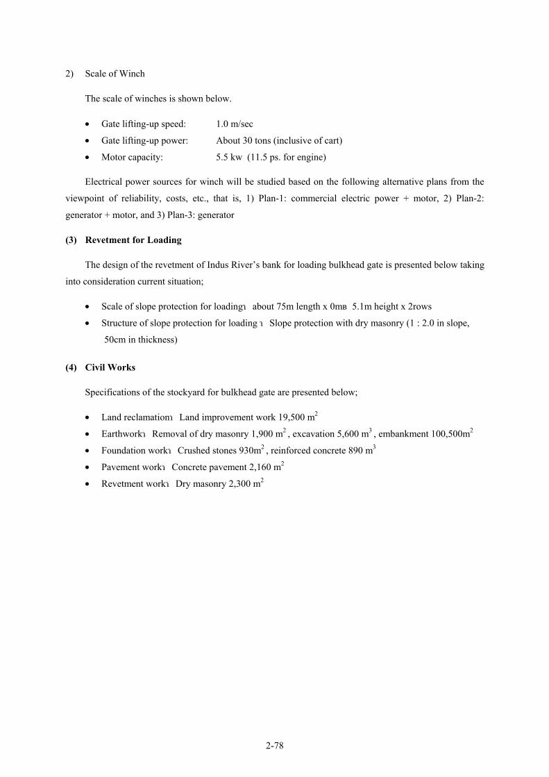
2-78
2) Scale of Winch
The scale of winches is shown below.
• Gate lifting-up speed: 1.0 m/sec
• Gate lifting-up power: About 30 tons (inclusive of cart)
• Motor capacity: 5.5 kw (11.5 ps. for engine)
Electrical power sources for winch will be studied based on the following alternative plans from the
viewpoint of reliability, costs, etc., that is, 1) Plan-1: commercial electric power + motor, 2) Plan-2:
generator + motor, and 3) Plan-3: generator
(3) Revetment for Loading
The design of the revetment of Indus River’s bank for loading bulkhead gate is presented below taking
into consideration current situation;
• Scale of slope protection for loading:about 75m length x 0m~5.1m height x 2rows
• Structure of slope protection for loading :Slope protection with dry masonry (1 : 2.0 in slope,
50cm in thickness)
(4) Civil Works
Specifications of the stockyard for bulkhead gate are presented below;
• Land reclamation:Land improvement work 19,500 m2
• Earthwork:Removal of dry masonry 1,900 m2 , excavation 5,600 m3 , embankment 100,500m2
• Foundation work:Crushed stones 930m2 , reinforced concrete 890 m3
• Pavement work:Concrete pavement 2,160 m2
• Revetment work:Dry masonry 2,300 m2

2-
79
1
st P
lan :
Com
mer
cial
Pow
er +
Mot
or
2 nd
Pla
n :G
ener
ator
+ M
otor
3
rd P
lan :
Engi
ne M
otor
C
apac
ity
Mot
or:
5.5k
w
Com
mer
cial
pow
er:
AC
400V,
50H
z ,3φ
M
otor:
5.5k
w
Gen
erat
or:
40K
VA×
1uni
t En
gine:
11.5
ps
Out
line
&
Equi
pmen
t C
ompo
sitio
n
The
plan
will
use
ele
ctric
pow
er. S
tand
by g
ener
ator
will
be
use
d on
ly in
cas
e of
pow
er st
oppa
ge to
bac
k up
ele
ctric
su
pply
for w
hole
Bar
rage
. Win
ch w
ill b
e dr
iven
with
m
otor
and
redu
cer.
The
plan
use
s gen
erat
or a
s ele
ctric
so
urce
. The
win
ch w
ill b
e dr
iven
with
m
otor
and
redu
cer.
The
plan
will
use
mot
or o
il to
star
t. N
o el
ectri
city
requ
ired.
W
inch
will
be
driv
en w
ith e
ngin
e, c
lutc
h, g
ear s
hifte
r and
re
duce
r, no
ope
ratin
g pa
ne n
eede
d.
Ope
ratio
nal
Effic
ienc
y
To b
e us
ed o
nly
whe
n tu
rnin
g on
the
brea
ker w
hich
m
akes
ope
ratio
n ea
sy. A
dvan
tage
in o
pera
tiona
l ef
ficie
ncy.
The
gene
rato
r nee
ds st
artu
p bu
t not
so
troub
leso
me.
N
eeds
to s
tartu
p en
gine
in n
eutra
l pos
ition
and
als
o ne
eds t
o re
vers
e sp
eed
of ro
tatio
n w
hen
build
ing
up sp
eed.
Rel
iabi
lity
on
Ope
ratio
n
Rel
iabi
lity
is h
igh
sinc
e th
is sy
stem
can
supp
ly p
ower
for
who
le B
arra
ge e
ven
in e
lect
ric st
oppa
ge. I
t has
stan
dby
gene
rato
r. E
lect
ricity
use
can
be
cont
rolle
d an
d be
ef
fect
ive.
Rel
iabi
lity
is h
igh
sinc
e th
is sy
stem
can
be
use
any
tim
e ev
en w
ith st
oppa
ge o
f co
mm
erci
al p
ower
. El
ectri
city
use
can
be
con
trolle
d an
d be
eff
ectiv
e.
・ C
an b
e us
ed e
ven
with
stop
page
of c
omm
erci
al p
ower
. ・ L
ow re
liabi
lity
beca
use
the
plan
nee
ds m
onito
ring
and
cont
rol a
y al
l tim
es b
y op
erat
or to
ens
ure
safe
ope
ratio
n.
Easi
ness
for
Mai
nten
ance
N
ot n
eces
sary
to m
aint
ain
the
equi
pmen
t but
nee
ds fo
r re
gula
r rep
lace
men
t to
leng
then
life
of t
he e
lect
rical
par
ts.
Gen
erat
or n
eeds
mai
nten
ance
. N
eeds
mai
nten
ance
for e
ngin
e et
c.
Ope
ratio
n ho
urs
2.2h
r (on
e w
ay)×
2 ×2
gate
s =8.
8hrs
2.
2hr (
one
way)×
2 ×2
gate
s =8.
8hrs
2.2h
r (on
e w
ay)×
2 ×2
gate
s =8.
8hrs
Freq
uenc
y2t
imes
/yea
r 2
times
/yea
r 2
times
/yea
r
Hours
Tota
l 17
.6hr
/yea
r 17
.6hr
/yea
r 17
.6hr
/yea
r C
onsu
mpt
ion
5.5k
W×
17.6
hr=
96.8
kWh
8 lit
./hr ×
17.6
hr=1
40.8
lit.
2.3
lit./h
r ×17
.6hr
=40.
5 lit
.
Initi
al C
ost
Ope
ratin
g pa
nel
300
thou
sand
Yen
C
ost f
or e
lect
rical
wor
k (ov
erhe
ad w
ire 5
00m)
3.
7 m
illio
n Y
en
Tot
al
4 m
illio
n Y
en
Ope
ratin
g pa
nel
300
thou
sand
Yen
G
ener
ator
3,00
0 th
ousa
nds Y
en
Tota
l 3.
3 m
illio
n Y
en
Engi
ne c
lutc
h 80
0 th
ousa
nd Y
en
Gea
r shi
ft eq
uipm
ent
3.5
mill
ion
Yen
To
tal
4.3
mill
ion
Yen
Run
ning
C
osts
In c
ase
of 1
kWh=
11 Y
en (i
n Ja
pan)
; (
assu
med
that
bas
ic ra
te in
clud
es in
the
runn
ing
cost
of
gate
bec
ause
the
mot
or w
ill n
ot b
e op
erat
ed
sim
ulta
neou
sly
with
the
gate)
A
nnua
l cos
t 96
.8×
11=
1.1
thou
sand
Yen
C
ost f
or 5
0 ye
ars :
1.1 ×
50 y
ears
=55
thou
sand
Yen
In c
ase
of 1
lit. =
50Y
en;
Ann
ual c
ost
140.
8 ×50
Yen=
7.1
thou
sand
Yen
C
ost f
or 5
0 ye
ars :
7.1 ×
50 y
ears
=355
th
ousa
nd Y
en
In c
ase
of 1
lit. =
50Y
en;
Ann
ual c
ost
40.5×
50 Y
en=
2.1
thou
sand
Yen
C
ost f
or 5
0 ye
ars :
2.1 ×
50 y
ears
=105
thou
sand
Economical Efficiency
Life
Cyc
le
cost
s
Initi
al c
ost:
4,00
0 th
ousa
nd Y
en
Run
ning
cos
t :55
thou
sand
Yen
Li
fe c
ycle
cos
t:4,
055
thou
sand
Yen
Initi
al c
ost:
3,30
0 th
ousa
nd Y
en
Run
ning
cos
t :35
5 th
ousa
nd Y
en
Life
cyc
le c
ost:
3,65
5 th
ousa
nd Y
en
Initi
al c
ost:
4,30
0 th
ousa
nd Y
en
Run
ning
cos
t :10
5 th
ousa
nd Y
en
Life
cyc
le c
ost:
4,40
5 th
ousa
nd Y
en
Eval
uatio
n ○ :
Hig
h re
liabi
lity
but i
neff
icie
nt in
mai
nten
ance
and
ec
onom
y. N
o m
erit
coul
d be
foun
d fo
r its
use
. ◎:
Mos
t sui
tabl
e am
ong
the
thre
e (3
) pl
ans d
ue to
goo
d ec
onom
ical
ef
ficie
ncy
and
high
relia
bilit
y.
△ :
No
mer
it ca
n be
foun
d du
e to
pro
blem
in o
pera
tion
and
low
eco
nom
ical
eff
icie
ncy.
2-79
Tab
le 2
-2-2
.14
Exa
min
atio
n T
able
on
Ele
ctri
c So
urce
for
Win
ch fo
r St
ocky
ard
of B
ulkh
ead
2-80
2-2-2-8 Electrical Facilities
Capacity calculations for electrical facilities are as follows.
(1) Motors for Under Sluice Gate and Weir Gate
According to the earlier assessment of hoist motor output, rated output shall be 2.2 kW of under sluice
gates, 1.5 kW of weir gates.
(2) Transformer for Receiving Equipment
Conditions : Simultaneous operation shall be possible up to 10 gates of under sluice gate.
Ptr = [{Po/(η・Pf)}+Pi]α
Where,
Ptr : Transformer capacity (kVA)
Po : Output of each load (kW) (2.2kW x 10 =22kW)
η : Efficiency of each load
Pf : Power factor of each load
Pi : Load capacity other than Po (kVA)
for Local Control Panel: 0.5kVA x 10 = 5kVA
for LV Panel: 2kVA (Total: 7kVA)
α : Demand factor
Ptr = [{22 / (0.85 x 0.80)}+7 ]x 1.0
= 39.3 (kVA)
From the above, based on standard capacity of the nearest transformer, 50 kVA shall be selected.
(3) Backup Generator for Gates
Assessment of the backup generator is shown in Appendix-A6-8. As a result of the examination, 50 kVA
is selected.
(4) BHG Winch Motor
According to the earlier assessment of BHG winch output, rated output shall be 5.5 kW (refer to 2-2-2-1).
(5) Generator for BHG winch
Assessment of the generator is shown in Appendix-A6-9. As a result of the assessment, 50 kVA is
selected.

2-81
Table 2-2-2.15 Specifications of Main Electrical Equipment
Main Equipment Quantity to be Procured Outline Specifications
(1) Power receiving equipment Terminal pole 1 set Electric pole, assembling fittings, naked wire Fused disconnecting switches 3 sets 11kV, 10A Lightning arrester 3 sets 11kV, 5kA, gapless type Transformer 1 unit 11/0.4-0.23kV, 50kVA
Outdoor installed type, oil-immersed (2) Power distribution equipment
Low voltage switchboard 1 unit Outdoor self-standing type (3) Switchgear 29 sets
Local Control panel Outdoor self-standing type, IP54 Motor Cage 3-phase induction motor, outdoor type, with
electromagnetic brake, 1.5 kW for weir gate and 2.2kW for under sluice gate
Gate position meter Electric type Limit switch box Fitted with 2 limit switches
(4) Backup generation equipment (for gates)
Generator 1 unit Diesel engine 400-230V, 50kVA
(5) BHG storage equipment Generator (for BHG) 1 unit Diesel engine
400-230V、50kVA Motor 1 unit Cage 3-phase induction motor, outdoor type, 5.5 kW Operation panel 1 unit Outdoor self-standing type, IP43
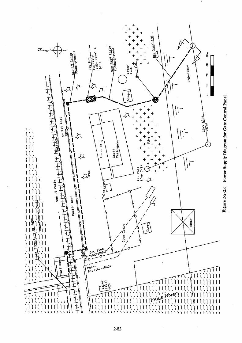


2-84
2-2-2-9 Temporary Facilities
(1) Temporary Diversion Channel
Temporary facilities are needed to flow river discharge to downstream safely in parallel with the
rehabilitation works in the River. The Taunsa Barrage will be provided with 53 weir gates (60ft=18.3m span
each) and 11 under sluice gates (60ft=18.3 span each). The weir gates and under sluice gates will be kept away
more than one gate from those being rehabilitated and will be used as temporary diversion channel in order to
flow river discharge safely.
If opening fully 12 gates, objective flood discharge that will take place during rehabilitation works could
be discharged. However, the regulation concerning gate operation of the Taunsa Barrage, namely “2 ft rule”
has been applied to control difference of gate opening of less than two (2) ft for two (2) neighboring gates.
Therefore detail gate operation will be planned for actual works in accordance with the “2 ft rule”.
(2) Cofferdam Work at Downstream for Gate Rehabilitation
① Water Level at Downstream of Cofferdam for Gate Rehabilitation
Water level during gate rehabilitation works will be D/S WL. 429.60ft = D/S WL. 130.94m, which are
those after construction of subsidiary weir at downstream.
② Crest Elevation and Structure of Cofferdam at Downstream
Crest elevation of cofferdam at downstream will be D/S WL. 429.60 ft = D/S WL. 130.94m + 0.5m of free
board at downstream of barrage.
・ Water level at downstream:D/S WL. 429.60 ft = D/S WL. 130.94m
・ Crest elevation of cofferdam at downstream:R.L. 432.00ft = EL. 131.67m
・ Elevation of existing incline apron:weir gate R.L. 425.00ft = EL. 129.50m
Under sluice gate R.L. 422.00ft = EL. 128.60m
・ Height of the cofferdam:Weir gate 7.00ft = 2.13m
Under sluice gate 10.00ft = 3.05m
Since the cofferdam will be constructed on the existing inclined apron due to the height of the cofferdam
which is relatively low, from 2.13m to 3.05m., the proposal is to utilize large size sandbags for the structure of
the cofferdam for easier construction and better water sealing.
(3) Temporary Road and Temporary Bridge
① Temporary Road

2-85
The existing main local road from Indus highway to the project site located at the right bank will be used
as temporary road. Power line with 4.5m height crossing road is higher than the limited height for road
construction (international standard). Accordingly there is no need to construct temporary road.
② Temporary Bridge
The existing attached bridge of the Taunsa barrage, the bridge at RD 7,500 Silt Ejector point, the existing
bridge at the intake of Muzaffarugarh and T.P.Link Canal, will be used as temporary bridge because these were
constructed to meet the design load for Class AA (design live load for 70tons tank) bridge.
There is no need to construct temporary bridge for weir gate and under sluice gate rehabilitation works
because construction works are planned to be undertaken from road bridge of the Taunsa Barrage or by using a
pontoon at the upstream.
(4) Temporary Jetty
The temporary pier for shipment of construction materials will be proposed because the construction
works are supposed to be done at the upstream by using a pontoon. Location of temporary jetty will be selected
at upstream of right bank because temporary stockyard for material and products is also planned at upstream of
right bank. Scale of the temporary jetty proposed is presented below;
・ Structure of temporary jetty:steel structure(H-300 x 300 L = 14.00m H-beam steel abutment、steel cover plates)
・ Width of temporary jetty:10.00 m(5.00 m x 2 lane) ・ Length of temporary jetty:30.00 m(inclined part:16.00 m、horizontal part:14.00 m)
2-2-2-10 Specifications and Quantities of Incidental Facilities and Equipment
Tables 2-2-2.16 and 2-2-2.17 show the specifications and quantities of incidental facilities and equipment
for the Project.
Table 2-2-2.16 Specifications of Bulkhead Gate Equipment Equipment Purpose of Installation Specifications Remarks Tug boat Towing of the bulkhead gate 150 PS x 2 vessels Boat Transportation of equipment
for installing the bulkhead gate, etc.
1.2 tons Capable of carrying work boat x 3 boats
3 boats for transporting compressors, etc.,
Main crane Assembly and disassembly of the bulkhead gate
50 t truck crane x 1 unit
Bulkhead gate Stockyard
Bulkhead gate storage and lifting at times of use
Concrete slope Winch 5.5 kW x 1 unit Generator 50 kVA x 1 unit
Spare parts Maintenance and repair work Bolts, nuts, packing, coating, maintenance tools for crane, etc., and so on
See Table 2-2-2.17 for details

2-86
Table 2-2-2.17 Bulkhead Gate Spare Parts Name Specifications Quantity Remarks
Tug boat maintenance tools Spanners, wrenches, etc. 1 set Planned for installation on each boat Filter For use with engines, oil
and air 5 sets Boat filters scheduled for replacement
every year Engine oil For tugboat and boat use 2 sets Replacement expected once per annum Crane maintenance tools Spanners, wrenches, etc. 1 set Crane oil Engine, mission, brakes 2 sets Planned for replacement every year Crane filters Engine, oil, air 2 sets Planned for replacement every year Crane element 2 sets Planned for replacement every year Brake oil 4 lit. Planned for replacement every 2 years Brake hose 1 set Planned for replacement every 2 years Electrical parts Fuses, lamps, etc. 1 set Bolts, nuts, packing 1 set Replacement expected once
2-2-2-11 Scope of the Project
On the basis of the proposal of the Preliminary Survey and present study results, the proposed scope of the
grant aid project is shown below.
Table 2-2-2.18 Scope of the Grant Aid Project
No Kind of Works Application by Pakistan Government
Proposal in the Preliminary Survey (Alternative 1)
Scope of Grant Aid Project
1 Replacement of the under sluice gate at left bank 7gates 7gates 7gates
2 Rehabilitation of the weir gate facilities 24gates 24gates 22gates
3 Replacement of old-type gate hoist to new type and rehabilitation
60gates(under sluice gate:7gates, weir gate:
53gates)
31gates(under sluice gates:7gates, weir gate:
24gates)
29 gates(under sluice gates:7gates, weir
gate:22gates) 4 Electrification of gate hoist 31gates(under sluice
gate:7gates, weir gate:24gates)
31gates(under sluice gate:7gates, weir gate:
24gates)
29 gates(under sluice gate:7gates, weir gate:
22gates) 5 Rehabilitation of deck on
superstructure 60gates(under sluice gates:7gates, weir
gate:53gates)
65gates(under sluice gate:11gates,
weir gate:53gates, navigation lock:1gate)
65gates(under sluice gate:11gates,
weir gate:53gates, navigation lock:1gate)
6 Provision of bulkhead gate for temporary cofferdam works
6 gates 6 gates 5 gates (including side
frames and sill beams for 29bays)
7 Construction of stockyard for bulkhead gate and slope protection works for loading way
1set 1set 1set
8 Provision of construction machinery
One (1)set of 80t & 30t cranes, two (2) tugboats
and three (3) boats
One (1)set of 80t & 30t cranes, two (2) tugboats
and three (3) boats
One (1)set of 50 t crane, two (2) tugboats 150ps
and three (3) boats 9 Spare parts for item 8 1set 1set 1set

2-87
2-2-3.Basic Design Drawings
List of Basic Design Drawings
Drawing No. Drawing Title
DWG-1 General Layout of Taunsa Barrage Rehabilitation Project
DWG-2 General Elevation of Taunsa Barrage
DWG-3 General Profile of Taunsa Barrage
DWG-4 General Layout of Under Sluice Gate Facilities
DWG-5 Layout of Under Sluice Gate Leaf
DWG-6 Layout of Under Sluice Gate Hoist
DWG-7 General Layout of Weir Gate Facilities
DWG-8 General Layout of Weir Gate Hoist
DWG-9 General Layout of Bulkhead Gate Facilities
DWG-10 Layout of Bulkhead Gate Leaf
DWG-11 Layout of Bulkhead Gate Stockyard
DWG-12 Layout of Deck Plate Rehabilitation
DWG-13 Low Voltage Switchboard Outline and Single Diagram
DWG-14 Local Control Panel Outline and Single line Diagram


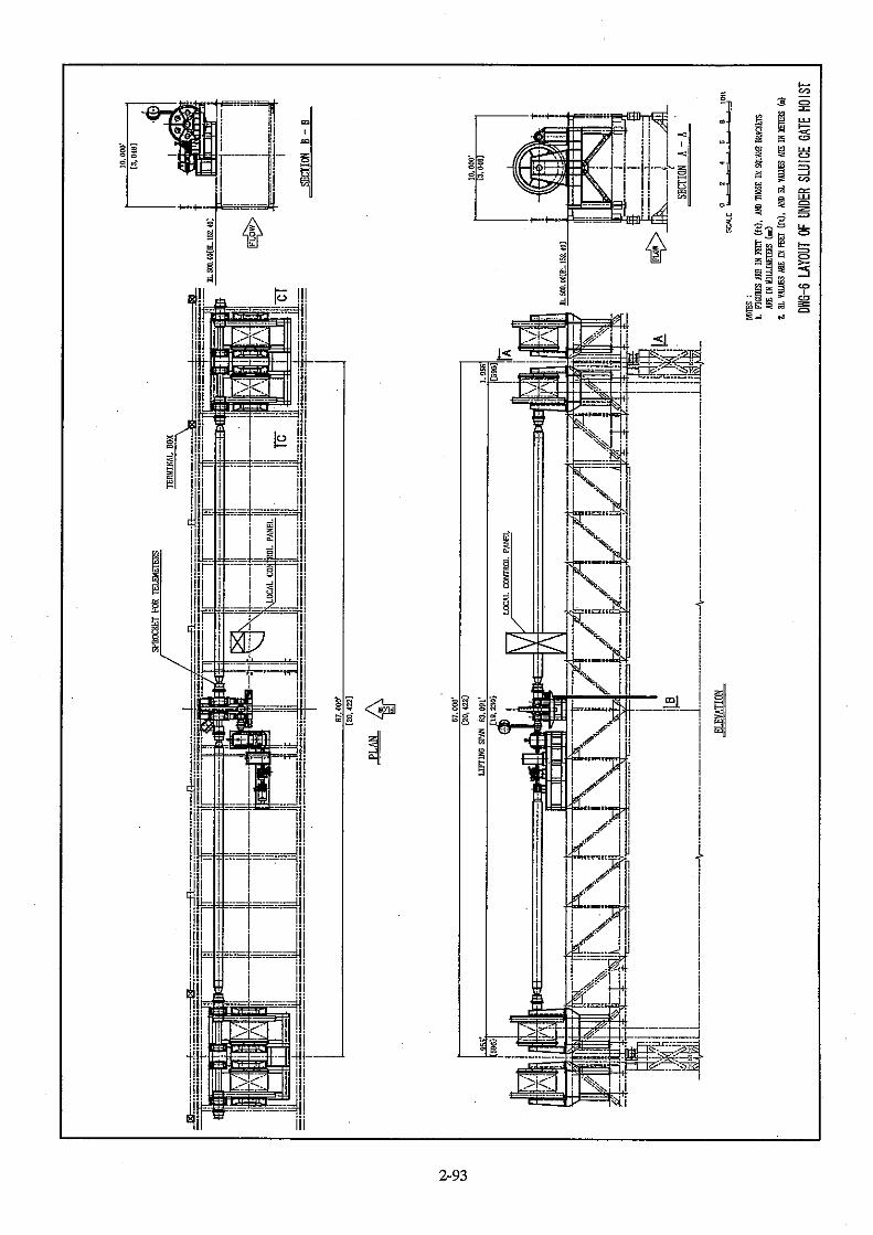

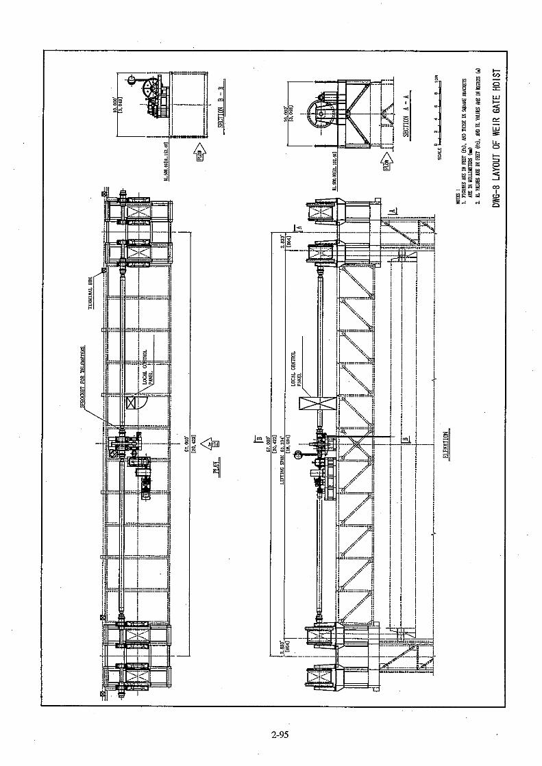


2-102
2-2-4 Implementation Plan
2-2-4-1 Implementation /Procurement Policy
The proposed item of works for the gate rehabilitation of Taunsa Barrage includes the following: 1)
rehabilitation of weir gates, 2) replacement of under sluice gates, 3) rehabilitation and electrification of gate
hoist, 4) rehabilitation of deck on superstructure, 5) installation of bulkhead gates, and 6) construction of
stockyard for bulkhead gates. The item of works proposed to be rehabilitated will be carried out under the
Japan’s Grant Aid Scheme. The implementation agency from the government of Pakistan is the Irrigation
and Power Department (IPD).
(1) Notices in Construction
① River Flow Control and Discharge Management under Construction
The number of gates to be rehabilitated is as follows:
1) Weir gate; 22 out of existing 53 numbers.
2) Under sluice gate; 7 out of existing 11 numbers.
During gate rehabilitation works, the control of both flows of Indus River and of downstream at
Taunsa Barrage shall be done by using the remaining existing weir gates.
② Cofferdam Construction
Upstream of the Taunsa Barrage
The cofferdam of the upstream part that will block the river flow will be undertaken by using the
bulkhead gates that will be procured in this Project. To ensure the function of water seal and stability of
bulkhead gate, careful planning and supervision will be required.
Downstream of Taunsa Barrage
The cofferdam at the downstream will be established by putting large size sandbags on the existing
inclined apron. To avoid causing damages to the apron and to secure stability of the large size sandbags
installed, careful planning and supervision will be required.
③ Measures for Existing Public Facilities
The Taunsa Barrage is equipped with several facilities such as railway, road bridge, electricity,
pipelines for domestic water and gas, and communication facilities. These facilities will still be operated
even during construction of the Project. Therefore, the construction / rehabilitation works will require the
advance approval of agencies concerned.
④ Environment control measure
During construction, measures to minimize environmental impact such as water pollution and others

2-103
are required to be taken into consideration.
⑤ Temporary Yard
IPD will be responsible to secure necessary permissions and approval for the use of temporary yard
for construction/rehabilitation works before commencement of the Project. Therefore, the permissions
concerning land use for temporary yard shall be secured in advance according to the drawings of the basic
design.
(2) Application of Local Steel Structure Manufacture
There are local manufacturers/plants within the area with sufficient experience in steel works. Hence,
the gate that will be required for the Project such as bulkhead gate, under sluice gate, weir gate and etc.,
will be locally manufactured.
(3) Local Contractor’s Participation
Local contractors will also be tapped to participate in the construction works of the Project in terms of
undertaking inland transportation, supplying construction equipment, undertaking earth works, steel
structure construction, and supplying the construction material and labor.
(4) Dispatch Plan of Japanese Technician
In Pakistan, there are only very limited number of local people with experience in the installation of
gate works. Under the Project, technical experts from Japan will be dispatched to provide necessary
training and on-the-job experiences to the local staff/ laborers in the installation and operation of the gates
that will be provided. Initially, there will be a larger number of technicians from Japan that will be
dispatched to provide support, assistance and training to local staff/labor. Eventually, as the work
progresses and is completed, the number of technicians will be decreased, accordingly.
Table 2-2-4.1 Scope of Work for Technicians to be Dispatched
Job classification Number of Technician to be dispatched Period Scope of works
Civil Engineer 1 10 M/M 1) Take charge of installation of sheet pile and H-beam of temporary jetty
Technician for installation of gate equipment
1~8 96.5 M/M 1) Assembly of bulkhead gate and installation of guide frames
2) Installation of under sluice gates 3) Rehabilitation of weir gates 4) Installation of gate hoist
Technician for installation of electrical equipment
1~2 14 M/M 1) Installation of power receiving and transformer facilities (Including standby generator facilities)
2) Installation of electric gate hoist for under sluice gates and weir gates
Gate operation instructor 1 5.5 M/M 1) Confirmation of function and operating instruction for gate facilities

2-104
2-2-4-2 Conditions on Implementation/Procurement
(1) Construction Period and Actual Working Days
Since the gate rehabilitation will be made using bulkhead gate, the construction period of the work
will be limited to the dry season, which is eight (8) months from middle of September to middle of May.
Since rainfall is usually minimal during this period, there is no need to consider idle days due to rainfall.
Sundays and Friday afternoons are usually considered holidays in Pakistan. Since work schedule for
the maintenance works of the barrage is concentrated in January (annual closure period), the construction
and rehabilitation works of the project should be done continuously even during the above-mentioned
holidays. It is also noteworthy to consider in the work plan that labor capability decreases around
November, which is the period of Ramadan.
(2) Water Level Rising of Downstream in the Indus River by the Subsidiary Weir
The river water level at the downstream of the Barrage is expected to rise due to the subsidiary weir,
which is to be constructed at downstream area of the barrage by Pakistan side. Since the construction of the
subsidiary weir will be set by river diversion method which closes half of the river width, degree of the
river water level is supposed to be relatively high during construction period of the subsidiary weir. When
the Indus River discharge increases during the period, the water level of river downstream should be
carefully watched.
(3) Utilization of Installation Section of the Local Mill Manufacturer and Welder
Welders and installation workers who will be engaged in the gate rehabilitation work have to pass
required qualification criteria of JIS or AWS to be technically eligible. In view of this, it is planned to tap
the expertise of local mill manufactures and/or technicians in the production and installation work of gates,
plant facilities and so on.
(4) Utilization of Local Steel Materials Available in Pakistan
Considering the manufacturing period for steel structure, local-made steel material available should be
used as much as possible. However, local materials that will be used should meet ASTM, BS, and JIS etc.
Standards. Furthermore, to control quality of manufactured gates using mill sheets and/or materials,
necessary inspection as needed will have to be undertaken.
2-2-4-3 Undertaking in Implementation and Procurement
(1) Land Acquisition and Land Rental
The Government of Pakistan will be responsible for preparing the land for temporary works. The
temporary yard (1,500m2) for keeping construction materials is proposed to be located at the right bank at
the upstream of the Taunsa Barrage. The proposed offices, lodgings and laboratory, etc. (2,700m2) is
planned to be constructed along the left bank of the TP Link Canal that is placed at the upstream of the

2-105
Taunsa Barrage. Both lands mentioned above belong to the Government, hence, it will not be necessary
to compensate for the land that will be used during construction and rehabilitation works.
Based on Guideline of the Japanese Grant Aid Scheme, cost of land and land leveling are considered
counterpart contribution to be provided by the Government of Pakistan. Backfilling and restoration works
are to be provided under the Government of Japan assistance.
(2) Undertaking of Electric Power Receiving Facilities
Power from the existing 11KV high voltage power line running near the Taunsa Barrage will be
tapped for the Project. This existing power line is drawn into the site of Taunsa Barrage O&M office. In the
site of the management office, the power receiving facility is planned to be obtained from the existing
11KV high voltage power line through the connecting line (L=50m), which will be newly drawn by
diverting from the existing line. The electricity will be transmitted from the power receiving facility to the
barrage through the low voltage power cable.
The connecting line which will be newly established from the existing 11KV high voltage power line to the site of the Barrage O&M office.
To be undertaken under Japan’s Grant Aid
The power receiving facility to be constructed near the Barrage O&M office and the low voltage power cable to be connected from the power receiving facility to the Barrage
To be undertaken under Japan’s Grant Aid
Figure 2-2-4.1 General Power Supply Diagram
Undertaking of Electric Power Receiving Facilities
Office Facility (IPD)
Telemetry System (WAPDA)
Gate Cont. System (New Facility)
New Facility
Existing Facility
Workshop Facility (IPD)
Taunsa Workshop
Taunsa Barrage
11kV
MEPCO Kot-Addu
Feeder-DDP
Feeder-4
11kV
3.3kV 400/230V
400/230V
400/230V
by IPD
TR

2-106
2-2-4-4 Consultant Supervision and Procurement Supervision Plan
(1) Contractor’s Supervision plan
This plan consists of the procurement of the shop fabrication of the gate leaves and the guide frames
for the large gates, the rehabilitation work of the removal/installation and the repair, along with the
corresponding civil work.. Rehabilitation works of the large gates will require experienced mechanical
and electrical engineers, as it will need careful safe management and progress/quality control. Civil works
will require civil engineers, with sufficient construction skill of this kind and construction experience in
Pakistan, because local material will be used for nearly all material, and they can employ local
subcontractors or local laborers to implement the construction.
The construction works for the proposed projects will require chief engineers that can lead and take
actions and quick decision at the site, as needed. The work will require strict control and supervision of
work progress because each repair work has to be finished within four (4) months between the annual
closure period and the flood season, and adjustment of the rehabilitation work of main body of the Barrage,
which is carried out by the Government of Punjab province.
The proposed dispatch of Japanese engineers/experts is planned based on the above mentioned
consideration (refer to Table 2-2-2.2).
Table 2-2-4.2 Residential Specialists Engineers Assignment Plan
Post Grade Period Scope of works
Manager 2 39 Months
Overall management of the whole construction works; safety and security control; coordination, deliberation and adjustment with a client;, and adjustment and negotiation with the provincial Government for the repair work of the Barrage
Chief Engineer 2 37 Months
Overall construction plan of the repair work of the Barrage by the provincial Government; Construction supervision and progress control/adjustment
Civil Engineer 3 32 Months
Construction plan and supervision, quality and safety control of the whole civil works
Civil Engineer 3 14 Months
Quality and progress control when construction plan of incline works and temporary works are executed at the same time
Mechanical Engineer A 3 38
Months Construction plan of mechanical works, and quality and construction supervision for gates works
Mechanical Engineer B 3 15
Months Quality and construction supervision for gates works when two works are executed at the same time
Electrical Engineer 3 12
Months Construction plan of electrical works, and quality and construction supervision
Quality Control Engineer 3 8
Months Confirmation of function of the gate, and instruction and guidance of gate operation
Clerical Manager 4 39 Months
Custom clearance and transport of equipment and materials, labor management and public relations
(2) Liaison and Communication Management
It is planned to establish a liaison office in Lahore city for shop fabrication, procurement and

2-107
transportation arrangement of equipment and materials from Lahore, and maintaining communication link
with the client.
(3) Safety Control Management
The Japanese Government does not consider the project site area in Punjab province as security risks
as compared with other areas in Pakistan. No cases of terrorism targeting foreigners have recently been
reported and troops, which were deployed near the border between India and Pakistan, have already
withdrawn. Therefore, the area has no security problem so far.
(4) Detail Design and Supervision Management by Consultants
For the detailed design and preparation of tender documents, it is proposed to assign the following
Japanese staffs as shown in Table 3-2-4-4.2.
Table 2-2-4. 3 Detailed Design Staff Plan
Post Grade Duties
Manager (Chief Engineer) 2 Compilation of design outputs and finalization of design and tender documents
Design Engineer for Hydraulic structures/Civil 3 Site investigation and design of civil (design drawings)
Design Engineer for Steel structures (A) 3
Site investigation and design of steel structures, determination of gates specification (under sluice gates and weir gates), Examination of Equipment & installation specifications
Design Engineer for Steel structures (B) 3
Design of steel structures (Hoisting devices and decks works of superstructure), Examination of Equipment & installation specifications
Design Engineer for Steel structures (C) 3 Determination of gates specification, structure design calculation,
design drawings and quantities calculation for bulkhead gates Design Engineer for Steel structures (D) 4 Structure design calculation, design drawings and quantities
calculation for under sluice gates and weir gates Design Engineer for Steel structures (E) 4 Structure design calculation, design drawings and quantities
calculation for operating facilities and decks of upper works Electrical Equipment Engineer (A) 3 Determination of electrical equipment specification, calculations,
design drawings and quantities calculation Electrical Equipment Engineer (B) 4 Compilation of detailed design of electrical equipment and
preparation of specification Cost estimate and procurement specialist 3 Cost estimation based on detailed design and review of cost
estimate made at the time of basic design Specification specialist on Civil Works 3
Preparation of Specifications of civil works in accordance with the results of the detailed design
Specification specialist on gate manufacturing (A) 3 Preparation of Specifications of gate manufacturing in accordance
with the results of the detailed design Specification specialist on gate manufacturing (B) 3 Preparation of Specifications of gate manufacturing in accordance
with the results of the detailed design
Tender document specialist 3 Compilation of all detailed design outputs and preparation of tender documents
Drawing expert 6 Preparation of detailed design drawings
Assistant engineer 6 Assist quantities calculation and cost estimation

2-108
This project is mainly planned to repair steel structures, replace existing under sluice gates, change
side girder of weir gates, repair guide frames, replace gate hoists, and so on. Resident supervisor that will
be assigned by the consultants shall be one with adequate knowledge and experience on steel structures
such as a gate.
Details of construction supervision works for the gate to be executed by the consultants including
works in Japan and in Pakistan are shown in Table 2-2-4. 4.
Table 2-2-4. 4 Construction Supervision Works for the Gate
Work site Contents
In Japan Drawing approval, inspection of shop fabrication, inspection of packing and confirmation of documents on export.
In Pakistan Drawing approval, inspection of shop fabrication, inspection of packing, issuance of work progress certificates, inspection on completion and issuance of completion certificates.
For the construction supervision by the Consultants, the following staffs from Consultants are
proposed as shown in Table 2-2-4.5.
Table 2-2-4. 5 Staffs for Construction Supervision
Post Grade Duties
Manager (Chief engineer) 2 Pre-qualification in tender process and technical evaluation of tender
Resident supervisor 3 Inspection at site and advice on coordination, schedule, quality and safety for all over works of shop fabrication civil, mechanical and electrical equipment works. Drawing approval and design change approval for civil, mechanical and electrical equipment works, and advice on maintenance and operation.
Electrical design engineer (by spot)
3 Staggered assignment as required and necessary during construction works for advice and guidance. Approval of drawings for electrical works.
Mechanical design engineer (by spot)
3 Staggered assignment as required during construction for advice and guidance. Approval of drawings for mechanical works.
Inspector (in Japan) 3 Inspection in Japan for domestic fabrication
For the supervision of procurement such as bulkhead gate, truck crane, tugboat, work boat, which will
be tendered as equipment supply project separately, staffs from Consultants are proposed as shown in Table
2-2-4.6.
Table 2-2-4.6 Staffs for Supervision of Equipment Procurement
Post Grade Duties
Manager (Chief engineer) 2 Pre-qualification in tender process and technical evaluation of tender
Tender document Expert 3 Compilation of tender document for equipment supply project Inspector (In Pakistan) 3 Inspection in Pakistan for equipment supply project Inspector (in Japan) 3 Inspection in Japan for equipment supply project

2-109
2-2-4-5 Quality Control Management
Quality control for the works is planned as shown in Table 2-2-4.7.
Table 2-2-4. 7 Quality Control Plan (Construction)
Works Items to be controlled Method Frequency
Excavation bed
Soil condition Width/height
Visual Measurement of dimension/height
For major parts For major parts
Embankment Compaction degree In-site density test Every 400m2
Concrete
Aggregate Cement Fresh concrete Concrete strength
Grain-size analysis test Physical test/Chemical test Slump/Air content/Chloride Compressive strength test
Every 3,000m3 Every 1,000ton Every placement Every 200m3
Reinforcement bar
Strength Assembling condition
Tensile strength test Rebar assembling inspection
Every 200ton Every part
Structure as built As built dimension Measuring dimension For major parts Mechanical equipment
Installation accuracy Function
Installed position measurementLoaded operation test
For all equipment For all equipment on operation test
Table 2-2-4. 8 Quality Control Plan (Fabrication) Items to be controlled Method Inspection equipment Inspection site
Collation of mill sheet Inspection report of parts maker
Confirmation of material and equipment parts Material test
Fabricating Factory
Visual inspection Confirmation of welding Non-destructive inspection
X ray camera Factory and on-site
Confirmation of dimension Measuring major dimension Steel tape, Scale Factory and on-site
Visual inspection Confirmation of temporary assembly Measuring major dimension
Steel tape, Scale, Level, Transit Factory
Confirmation of painting
Measuring coating thickness and photograph Coating thickness gauge Factory and on-site
Confirmation of Installed position Installed position measurement Steel tape, Level, Transit On-site
Confirmation of functions
Measuring of speed, electric current/voltage, temperature rising at driving part through test runs Confirmation of water-stops
Ammeter, Voltmeter, Stopwatch, Thermometer
Factory (hoists) and on-site
2-2-4-6 Procurement Plan
(1) General-Purpose Construction Materials
Cement, reinforcement bar, timber, general-purpose building material, electric cable, piping material
etc are available in Pakistan. Majority of construction materials are planned to be procured in Lahore city.
Course and fine aggregate for concrete and crushed stone for masonry are planned to be procured in D. G.
khan.
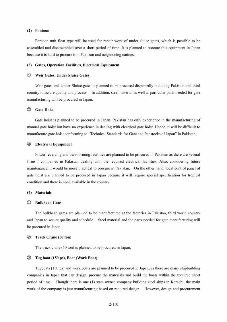
2-110
(2) Pontoon
Pontoon unit float type will be used for repair work of under sluice gates, which is possible to be
assembled and disassembled over a short period of time. It is planned to procure this equipment in Japan
because it is hard to procure it in Pakistan and neighboring nations.
(3) Gates, Operation Facilities, Electrical Equipment
① Weir Gates, Under Sluice Gates
Weir gates and Under Sluice gates is planned to be procured dispersedly including Pakistan and third
country to assure quality and process. In addition, steel material as well as particular parts needed for gate
manufacturing will be procured in Japan.
② Gate Hoist
Gate hoist is planned to be procured in Japan. Pakistan has only experience in the manufacturing of
manual gate hoist but have no experience in dealing with electrical gate hoist. Hence, it will be difficult to
manufacture gate hoist conforming to “Technical Standards for Gate and Penstocks of Japan” in Pakistan.
③ Electrical Equipment
Power receiving and transforming facilities are planned to be procured in Pakistan as there are several
firms / companies in Pakistan dealing with the required electrical facilities. Also, considering future
maintenance, it would be more practical to procure in Pakistan. On the other hand, local control panel of
gate hoist are planned to be procured in Japan because it will require special specification for tropical
condition and there is none available in the country
(4) Materials
① Bulkhead Gate
The bulkhead gates are planned to be manufactured at the factories in Pakistan, third world country
and Japan to secure quality and schedule. Steel material and the parts needed for gate manufacturing will
be procured in Japan.
② Track Crane (50 ton)
The truck crane (50 ton) is planned to be procured in Japan.
③ Tug boat (150 ps), Boat (Work Boat)
Tugboats (150 ps) and work boats are planned to be procured in Japan, as there are many shipbuilding
companies in Japan that can design, procure the materials and build the boats within the required short
period of time. Though there is one (1) state owned company building steel ships in Karachi, the main
work of the company is just manufacturing based on required design. However, design and procurement

2-111
of materials are being done by their clients.
2-2-4-7 Implementation Schedule
In the implementation schedule, it is planned that:
1) Detailed design and preparation of tender documents will require 5.5 months
2) Tendering and selection of contractor for rehabilitation main works will require 3.5 months
It is proposed to conduct tender and selection of contractor for procurement of Bulkhead gates, Truck
Crane, Tug Boat and Work Boat as soon as possible, taking into account the tight schedule until
commencement of the main works which is planned to use the Bulkhead Gate. The repair works of gates
are planned to commence from February 2007 because the guide frames for bulkhead gates is indispensable
for the implementation of the gates repair that are to be installed during the annual closure period.
It is necessary to provide all five (5) gates by the time construction starts on February 2007, due to
Bulkhead gates being assembled 9-separated pieces into one (1) component at the site. Considering the
assembly days required for a gate, start of assembly for the first gate will be by October 2006. Therefore,
it is planned that the period for procurement of Bulkhead gate shall be 11.5 months for the first gate from
Contract to Procurement to the site, and 14.5 months for last gate (No.5 gate). Other equipment to be
fabricated at the factory will not affect the overall schedule since there is sufficient time for procurement.
On the other hand, the schedule of the gate rehabilitation works is very tight. It will be carried out
using the procured five (5) bulkhead gates to the maximum use, and should be undertaken between the
annual closure period and the flood season of 3.5 months (one construction period). The rehabilitation
works include 22 weir gates and seven (7) under sluice gates, a total of 29 gates and it is expected to
commence from February 2007 to December 2008 (four (4) construction phases).
The gates that will be repaired in each construction period are planned as shown in Table 2-2-4.9.
The clearance and others will require about 2.5 months. Therefore the total construction period is 41
months from the Contract to the Completion, including fabrication, construction and site clearing.
Table 2-2-4. 9 Schedule of Gates Repair Works Target Gates to Repair
Phasing Duration Number of Gates No. of Weir Gates No. of Under Sluice
Gates 1st Construction Period
February - May, 2007 8 10,12,14,16,18,20,24,26 -
2nd Construction Period
September - December, 2007 8 11,13,15,17,19,23,25,27 -
3rd Construction Period
February - May, 2008 7 31,33,35,38 2,4,6
4th Construction Period
September - December, 2008 6 55,58 1,3,5,7
The detailed design and the tendering period are 9 months, while the rehabilitation works is 41 months,
a total of 50 months. Implementation schedule is shown in Figure 2-2-4.2.
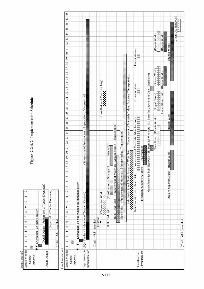
(Det
ail D
esig
n)La
psed
Mon
ths
12
34
56
78
910
1112
Cab
ine t
App
rova
lEN
Figu
re 2
-2-4
. 2
Impl
emen
tatio
n Sc
hedu
le(A
gree
men
t on
Det
ail D
esig
n)
(D
etai
l Des
ign
/ Pre
para
tion
of T
ende
r Doc
umen
t)
(App
rova
l of T
ende
r Doc
umen
t)
(Tot
alm
onth
s)
(Im
plem
enta
tion)
Laps
ed M
onth
s1
23
45
67
89
1011
1213
1415
1617
1819
2021
2223
2425
2627
2829
3031
3233
3435
3637
3839
4041
4243
4445
4647
48C
abin
e tA
ppro
val
EN
(Agr
eem
ent o
n Su
perv
isio
n on
Impl
emen
tatio
n)
(PQ
/ Te
nder
/ Ev
alua
tion
of T
ende
r / C
ontra
ct)(S
uper
visi
on o
f Pro
cure
men
t / S
uper
visi
on o
f Con
stru
ctio
n)
(Tot
alm
onth
s)C
ontra
ct(
Prep
arat
ion
Wor
k)(
Inst
alla
tion
of T
enta
tive
Jetty)
B
ulkH
ead
Gat
e:
(C
onst
ruct
ion
of S
tock
yard)
(
Ass
embl
y)
Bul
k H
ead
Gat
e:
( Pr
ocur
emen
t of M
ater
ials
/ M
anuf
actu
ring
/ Tra
nspo
rtatio
n)(機械設備
/製作
)G
ate
Hoi
st
(Pr
ocur
emen
t of M
ater
ials
/ M
anuf
actu
ring
/ Tra
nspo
rtatio
n)
Side
gird
er &
and
Gui
de F
ram
e of
Wei
r Gat
e:
(Pr
ocur
emen
t of M
ater
ials
/ M
anuf
actu
ring
/ Tra
nspo
rtatio
n)
Gat
e Le
af o
f U
nder
Slu
ice
Gat
e:
( P
rocu
rem
ent o
f Mat
eria
ls /
Man
ufac
turin
g) (
Tran
spor
tatio
n) (
Tran
spor
tatio
n)
Elec
trici
ty S
uppl
y Fa
cilit
ies:
(
Con
stru
ctio
n)
Gui
de F
ram
e fo
r Bul
k H
ead
Gat
e / S
ill B
eam
for W
eir G
ate
/ Sill
Bea
m fo
r Und
er S
luic
e G
ate:
(In
stal
latio
n)
Wei
r Gat
e: (
Rep
air W
ork)
(Rep
air W
ork)
(Rep
air W
ork)
(Rep
air W
ork)
Und
er S
luic
e G
ate:
(R
epai
r Wor
k)(R
epai
r Wor
k)
D
eck
of S
uper
stru
ctur
e:
(Rep
air W
ork)
(Rep
air W
ork)
(Rep
air W
ork)
(C
lean
-Up,
Han
dove
r)
(Tot
alm
onth
s)
44.5
Con
stru
ctio
n/ P
rocu
rem
ent
Det
ail D
esig
n
41.0
5.5
Supe
rvis
ion
onIm
plem
enta
tion
2-112

2-113
2-3 Obligations of Recipient Country
In order to secure smooth implementation and maintenance, outline of the measures to be undertaken by
the government of Pakistan during preparation, procurement of equipment, construction and operation and
maintenance is as follows.
2-3-1 General Obligations
1) To secure land necessary for the Project prior to commencement of the installation of the materials and
equipment,
2) To provide facilities of electricity and others needed for the Project in and around the sites,
3) To bear the necessary commission to the bank based on the Bank Arrangement,
4) To ensure prompt execution of customs clearance of the materials and equipment for the Project,
5) To exempt Japanese nationals from customs duties, internal taxes, and other fiscal levies which are
imposed in Pakistan with respect to the supply of materials, equipment and services or to bear the same,
6) To accord Japanese nationals who offer services for the Project to facilitate their entry into Pakistan and
stay therein for the performance of their works,
7) To operate and maintain the facilities and equipment provided under the Grant Aid properly and
effectively, To inform the condition of the operation and maintenance of the facilities and equipment as
Japanese side request,
8) To bear all the expenses other than those to be borne by the Grant Aid, necessary for the implementation
of the Project.
2-3-2 Obligations Prior to and during the Implementation of the Project
1) To complete the embankment works (about 100 thousand m3) of the stockyards for the bulkhead gates
before the beginning of the Project (October 2005),
2) To relocate the telemeter board (DAU) to appropriate place on the deck on responsibility of Pakistan
side after discussion with WAPDA in accordance with the installation works of the replacement of gate
hoist and the reinforcement works of the superstructures,
3) To inform the neighboring people completely that the bridge is going to close about 8.00-12.00 in the
morning and 13.00-17.00 in the afternoon during the construction except the flood season, using a
newspaper advertisement or a signboard,
4) Land acquisition and Land rental for temporary yard:
- To arrange the provision of land, cost for land and land leveling for the temporary yard (4,200m2)
neighboring to the site,
- To prepare land for disposal area of surplus soil materials,
5) To discuss matters with the Japanese persons concerned as the occasion demands in the construction
period in order to adjust the progress of the constructions and so forth between the Grant Aid Project
and the Punjab Barrages rehabilitation and modernization project by Pakistan.

2-114
2-4 Project Operation Plan
2-4-1 Organization of Executing Agency
(1) Organization of Executing Agency
The executing agency for the Project from the Government of Pakistan is the Irrigation and Power
Department, Government of the Punjab (hereinafter referred as IPD). The Department consists of seven (7)
Divisions holding about 52,400 staff in the whole Department. Organization chart of the Department is
presented below.
Figure 2-4.1 Organization Chart of IPD (2003/04)
The Taunsa Barrage Division (TBD) shown below will be responsible for operation and maintenance
(O&M) works for the improved equipment and materials. The Taunsa Barrage Division functions under the
DG Khan Zone Office. Its total staff is about 380.
Figure 2-4.2 Organization Chart of TBD
Executive Engineer
Sub Division officer (Bund Sub Division)
Sub Division officer (Workshop Sub Division)
Sub Division officer (Head Work Sub Division)
C Branch (Head Clerk)
Drawing Branch(Head Draftsman)
Accountant Branch Accountant
Sub Engineer (3) Sub Engineer (3) Sub Engineer (6) 1. Head Works 2. Hydraulic 3. Left Marginal Bank 4. Mechanical-1
(1) Civil Store (2) Fitting Shop (3) Work Shop
5. Mechanical-1 6. Electrical
Clarks (6) Draftsman (2) Tracer (2)
Accountant Clerk (5)
Silt Observer (1) Silt Analyzer (1)
Beldar (3)
Earth WorkMistry (2)
Forman (2) Head Jamadar (1)
Greaser (1) Electrician (1) Mechanic (2) Beldar (8)Gauge Reader (7)
Regulation Belder (35)
(Taunsa Barrage Division, Kot Adu)
IPD in Punjab Province
D.G.Khan Zone
Multan Zone
Lahore Zone
Planning Division
Research Division
Drainage Division
Muzaffargarh Canal Circle
Project Irrigation Circle
Drajat Circle
Taunsa Barrage Division (TBD)
Total staff Nos. of TBD: 380
Total Staff of IPD: 52,400

2-115
The major activities of TBD are; a) O&M works for Taunsa Barrage and river management facilities such
as river banks and spur dikes, etc. in the vicinities of the Barrage, b) O&M works for irrigation canals covered
by the Taunsa Barrage, c) collection and recording of climatological and hydrological data, d) periodical
observation of river conditions and shifting conditions of water route, etc, e) overall management for functions
of Taunsa Barrage. These activities will continually be undertaken even after the Project.
(2) Staff Arrangement
The Taunsa Barrage is presently operated and managed under the jurisdiction of TBD shown in Figure
2-4.2. With the total of 380 staff, the Division will still be able to cope with their existing functions and still
undertake the necessary O&M of the facilities and equipment that will be provided under the Project taking
into account the fact that TBD has been functioned in the O&M of the immense structures over about fifty
years. The TBD’s capacity with regards to O&M even in the future is considered good. The other required
staff needed for the newly installed facilities and the procured equipment such as electrification of gate
operation systems, five (5) units of bulkhead gate, inclination facilities, tugboats, cranes and etc., the TBD can
program an efficient and sufficient assignment system on rotating basis without adding to many staff as
follows.
1) Gate Operation Staff Numbers
Current gate operation staff in the TBD is 35 in total, 10 to 12 staff are normally stationed in the Barrage
on three (3) shifts. However, during the flooding period, temporary operation staffs are sometimes employed.
This Project principally consists of the improvement of necessary equipment for the existing Taunsa Barrage,
and operation and management works but even after the completion of the Project the current organization and
staff will still be able to cope with the O&M activities. However, with the introduction of electrification of
gate hoisting equipment, current gate operation staff could be reduced. The number of gate operation staff
may therefore be reduced. Based on survey of other existing facilities within the country, the number of staff
for similar facilities in other projects within the area are as follows:
・ Marala Barrage(weir gates: 46、under sluice gates: 20、total 66 gates、all radial gates, span:60 ft)
Gate operation staff : about 5 staff x 3 rotations = 15 staff
Temporary staff would be employed at flooding period.
Mechanical staff(mechanic, greaser, assistant): 10 staff
Electric engineer: 3 staff
・ Chashma Barrage(weir gates: 41, under sluice gate :11, total 52 gates, all radial gates, span: 60 ft)
Gate operation staff: 4 staff
Foreman: 1staff
Electric engineer: 4 staff
Helper: 10staff(for cleaning, etc.)
For the Project, 29 gates will be electrified, and remaining gates will be electrified with the
implementation of “the Punjab Barrages Rehabilitation and Modernization Project”to be undertaken by the

2-116
Government of Pakistan. Therefore, if all of the gates would be electrified, the total recommended staff will be
about 15 operation staff (3 shifts with about 5 staff each shift), equivalent to almost half of present staff of 35.
The reduced staff will be able to undertake O&M works, operation and management of the gates. There is also
the need to increase the number of electrical engineers and technicians because to be able to undertake their
work activities. The other TBD staff can take turns in the undertaking of the required work.
2) O&M Works for Bulkhead Gates and Their Operation Staff
For the O&M and management works of the new installed bulkhead gates of the Taunsa Barrage under
the Project, additional staff would be needed. The total bulkhead gates that will be introduced are 5 sets.
About 20 staff will be required for this facility. In addition, around 15 common laborers would be needed for
installation and removal of the gates during gate operation periods. For the operation and maintenance works
of the boats, which are related facilities for the operation of the bulkhead gates, five (5) captains would also be
needed. However, the current TBD staff in the fields of Head Boat Man, Boat Man, Motor Launch Driver,
Motor Launch Attendant, etc. maybe utilized instead for these required staff. Though electrical and technical
engineers and mechanics will be needed for the operation of the equipment (inclinations, cranes, etc.), the
required staff may be tapped from the TBD.
Necessary technical transfer of the O&M of the Bulkhead Gate and other newly provided equipment will be undertaken through “On the Job Training (OJT)”. Examples of possible OJT activities will include assembly and usage of the crane procured, towing by the tugboats and working boats, installation and removal at a bay of barrage, maintenance at the stockyard, and so forth.
2-4-2 Components of Operation and Maintenance Works
Operation and maintenance works for the equipment to be introduced by the Project are summarized
below. Maintenance and inspection works of the equipment would be required to be done periodically once a
year.

2-117
Table 2-4.1 Components of O&M Works of the Equipment
Class Medium Class Subclass Item MethodsPainting conditions Visual observation Repainting every 7-yearsBoard thickness Board thickness measurementGate leaning Visual observation/ confirmation
Watertight rubber Damages and degradation Visual observation/confirmation Replacement when needed
Roller damages and abrasion Surface visual confirmation andconfirmation
Roller rolling condition Operation confirmation
Side guide frame guide fram and abrasion Surface visual observation andconfirmation
Sill beam Damages and degradation Surface visual confirmation andconfirmation
Motor and relatedequipment Operation confirmation Abnormal noise/temperature rise
confirmation during operationElectric current and voltage Visual observation/ confirmationRefuel conditions Oil film confirmation
Tooth bearing Visual observation/ confirmationand measurement
Refuel conditions Visual observation/confirmation Repainting when neededWire cutting Visual observation/confirmation
Support unit Painting Repainting Repainting every 7-yearsPainting conditions Visual observation/ confirmation Repainting every yearBoard thickness Board thickness measurementGate leaning Visual observation/ confirmation
Watertight rubber Damages and degradation Visual observation/confirmation Replacement when needed
Roller damages and abrasion Surface visual observation andconfirmation
Roller rolling condition Operation confirmation
Side guide frame Girder damages and abrasion Surface visual observation andconfirmation
Sill beam Damages and degradation Surface visual observation andconfirmation
Motor and relatedequipment Operation confirmation Abnormal noise/temperature rise
confirmation during operationElectric current and voltage Visual observation/ confirmationRefuel conditions Oil film confirmation
Tooth bearing Visual observation/confirmation andmeasurement
Refuel conditions Visual observation/ confirmation Repainting when neededWire cutting Visual observation/confirmation
Support unit Painting Repainting Repainting every 7-yearsPainting conditions Visual observation Repainting every 7-yearsBoard thickness Board thickness measurementDamages Visual observation/confirmation
Watertight rubber Surface conditions Visual observation/confirmation Replacement when needed
Operation confirmation Abnormal noise/temperature riseconfirmation during operation
Insulation resistance value MeasurementMotor and relatedequipment Operation confirmation Abnormal noise/temperature rise
confirmation during operationElectric current and voltage Visual Observation/ confirmationRefuel conditions Oil film confirmationTooth bearing Visual confirmation andRefuel conditions Visual observation/ confirmation Repainting when neededWire cutting Visual observation/confirmation
Support unit Painting degradation Visual observation/ confirmationPainting conditions Visual observation Every 7-yearsdamages Visual observation/ confirmation
Resting Stand Support unit Painting conditions Visual observation Every 7-years
Operation confirmation Abnormal noise/temperature riseconfirmation during operation
Oil and filter replacement Replacement
Footboard Footboard Appearance deformation anddamages Visual observation/ confirmation
Structural Structural member Painting Repainting Every 7-years
Operation confirmation Abnormal noise/temperature riseconfirmation during operation
Oil and filter replacement ReplacementGenerator Insulation resistance value MeasurementControl Panel Electric current and voltage Visual observationControl Panel Insulation resistance value Measurement
Note 1) The contents of maintenance and inspection indicate the items for annual periodical matters only.
Engine
Electric Panel
Drum gear
Wire lope
Inclination &Winch
Compressor
Drum gear
Wire lope
Generator
Tug boat
Gtae Hoist
Cart
Gate
Compressor
Gate
Whole gate leaf
Roller train
Gate
ElectricEquipment
SuperStructures
Name of Equipment and Materials
Engine
Whole gate leaf
Guide Frame
BulkheadGates
Weir Gates
Bulkhead GateStockyard
Truck
Remarks
Under SluiceGates
Roller train
Guide Frame
Gtae Hoist Drum gear
Wire lope
Whole gate leaf
Contents of Maintenance and Inspection

2-118
2-5 Project Cost
2-5-1 Project Cost
Total cost needed for implementation of the Project under the Grant Aid is estimated at 5,469 million
yen. Based on the above, the itemized cost shares to be undertaken by Japan and Pakistan is estimated as
follows;
Total project cost estimation Approx. 5,469 million yen
(1) Cost to be Undertaken by the Government of Japan Approx. 5,281 million yen
Items Total (Million Yen)
Replacement of Under Sluice Gates 7 gates Repair of Weir Gates 22 gates Replacement & Electrification of Hoist 29 gates Improvement of Deck on Superstructure 1 lot
Facilities Rehabilitation of gate facilities and others
Incline 1 lot
3,676
Bulk-Head-Gate 5 gates Tug boat 150ps 2 unit Boat 3 unit
Equipment/Materials
50 ton Truck Crane 1 unit
1,192
Detailed Design and Construction Supervision 413Total 5,281
(2) Cost to be Undertaken by the Government of Pakistan Approx. 188 million yen
Thousand Rs Million Yen
Total 98,804 (Approx. 187.6)
①Reclamation of the Stockyard for Bulkhead Gate 14,808 (Approx. 28.1)
②Removal of control panel of telemeter system 353 (Approx. 0.7) ③Construction of Fence around the Stockyard for
Bulkhead Gate 257 (Approx. 0.5)
④Bank Service Charges 83,384 (Approx. 158.3)
(3) Estimation Basis
(a) Price level :As of September, 2004
(b) Foreign exchange rate :1 USD = 109.51 yen, 1Rs = 1.90 yen
(c) Construction period :Based on implementation schedule.
(d) Others: The projects shall be implemented in conformity with the provisions of the Japan Grant
Aid Scheme. The above total cost estimation shall not necessarily mean the limits of the
grant amount to be specified in the E/N.
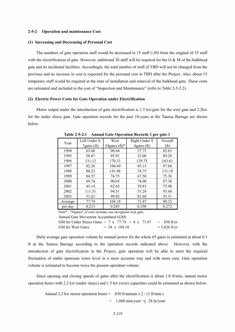
2-119
2-5-2 Operation and maintenance Cost
(1) Increasing and Decreasing of Personal Cost
The numbers of gate operation staff would be decreased to 15 staff (-20) from the original of 35 staff
with the electrification of gate. However, additional 20 staff will be required for the O & M of the bulkhead
gate and its incidental facilities. Accordingly, the total number of staff of TBD will not be changed from the
previous and no increase in cost is expected for the personal cost in TBD after the Project. Also, about 15
temporary staff would be required at the time of installation and removal of the bulkhead gate. These costs
are estimated and included in the cost of “Inspection and Maintenance” (refer to Table 2-5-2.2).
(2) Electric Power Costs for Gate Operation under Electrification
Motor output under the introduction of gate electrification is 1.5 kw/gate for the weir gate and 2.2kw
for the under sluice gate. Gate operation records for the past 10-years at the Taunsa Barrage are shown
below.
Table 2-5-2.1 Annual Gate Operation Records(per gate)
Daily average gate operation volume by manual power for the whole 65 gates is estimated at about 0.3
ft at the Taunsa Barrage according to the operation records indicated above. However, with the
introduction of gate electrification in the Project, gate operation will be able to meet the required
fluctuation of stable upstream water level in a more accurate way and with more ease. Gate operation
volume is estimated to become twice the present operation volume.
Since opening and closing speeds of gates after the electrification is about 1.0 ft/min, annual motor
operation hours with 2.2 kw (under sluice) and 1.5 kw (weir) capacities could be estimated as shown below.
Annual 2.2 kw motor operation hours = 830 ft/annum x 2 / (1 ft/min.)
= 1,660 min/year = 28 hr/year
Left.Under S. Weir Right.Under S Overall7gates (ft) 54gates (ft)* 4gates (ft) (ft)
1994 63.08 90.64 57.75 85.651995 58.07 95.91 53.00 89.201996 131.12 170.33 129.75 163.611997 82.26 100.60 85.15 97.681998 80.23 141.98 74.75 131.191999 84.57 74.75 67.50 75.362000 69.74 90.65 74.00 87.382001 45.14 82.65 39.83 75.982002 111.51 94.51 51.28 93.682003 51.63 99.82 81.68 93.51
Average 77.74 104.18 71.47 99.32per day 0.213 0.285 0.196 0.272
Note* : "54gates" of weir includes one navigation lock gate.Annual Gate Movement Accumlated (GM)GM for Under Sluice Gates = 7 x 77.74 + 4 x 71.47 = 830 ft/yrGM for Weir Gates = 54 x 104.18 = 5,626 ft/yr
Year
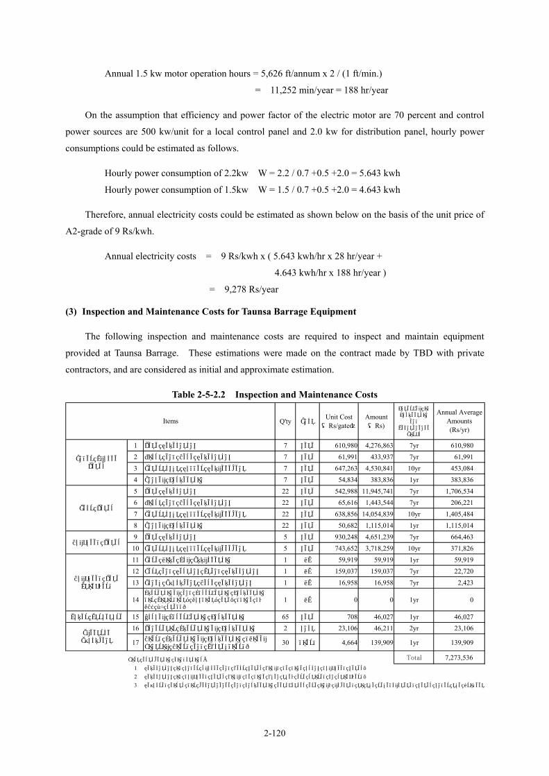
2-120
Annual 1.5 kw motor operation hours = 5,626 ft/annum x 2 / (1 ft/min.)
= 11,252 min/year = 188 hr/year
On the assumption that efficiency and power factor of the electric motor are 70 percent and control
power sources are 500 kw/unit for a local control panel and 2.0 kw for distribution panel, hourly power
consumptions could be estimated as follows.
Hourly power consumption of 2.2kw W = 2.2 / 0.7 +0.5 +2.0 = 5.643 kwh
Hourly power consumption of 1.5kw W = 1.5 / 0.7 +0.5 +2.0 = 4.643 kwh
Therefore, annual electricity costs could be estimated as shown below on the basis of the unit price of
A2-grade of 9 Rs/kwh.
Annual electricity costs = 9 Rs/kwh x ( 5.643 kwh/hr x 28 hr/year +
4.643 kwh/hr x 188 hr/year )
= 9,278 Rs/year
(3) Inspection and Maintenance Costs for Taunsa Barrage Equipment
The following inspection and maintenance costs are required to inspect and maintain equipment
provided at Taunsa Barrage. These estimations were made on the contract made by TBD with private
contractors, and are considered as initial and approximate estimation.
Table 2-5-2.2 Inspection and Maintenance Costs
Q'ty UnitUnit Cost(Rs/gate)
Amount(Rs)
Interval ofInspectionand
MaintenanceWorks
1 Gate Repainting 7 gate 610,980 4,276,863 7yr 610,980
2 Hoist and Base Repainting 7 gate 61,991 433,937 7yr 61,9913 Watertight Rubber Replacement 7 gate 647,263 4,530,841 10yr 453,084
4 Annual Inspection 7 gate 54,834 383,836 1yr 383,836
5 Gate Repainting 22 gate 542,988 11,945,741 7yr 1,706,5346 Hoist and Base Repainting 22 gate 65,616 1,443,544 7yr 206,221
7 Watertight Rubber Replacement 22 gate 638,856 14,054,839 10yr 1,405,4848 Annual Inspection 22 gate 50,682 1,115,014 1yr 1,115,014
9 Gate Repainting 5 gate 930,248 4,651,239 7yr 664,463
10 Watertight Rubber Replacement 5 gate 743,652 3,718,259 10yr 371,82611 Wire Lope Oil Application 1 LS 59,919 59,919 1yr 59,919
12 Cart and Resting Stand Repainting 1 LS 159,037 159,037 7yr 22,720
13 Winch Equipment Base Repainting 1 LS 16,958 16,958 7yr 2,423
14Operational and Observation Inspectionfor Motorboat, Tugboat, etc. (done byTBD 20 staff)
1 LS 0 0 1yr 0
Super Structure 15 Visual Observation Inspection 65 gate 708 46,027 1yr 46,02716 Generator Operational Inspection 2 unit 23,106 46,211 2yr 23,106
17 Board Operational Inspection (LocalControl Board and Switchboard) 30 board 4,664 139,909 1yr 139,909
Cost estimation conditions; Total 7,273,5361 Repainting of under sluice and weir gates would be done using bulkhead gates.2 Repainting of bulkhead gates would be done when they are stored in stockyard.3 Required costs for maintenance and inspection activities are only limited to the rehabilitated gates under the Project
ItemsAnnual Average
Amounts(Rs/yr)
Under SluiceGates
Weir Gates
Bulkhead Gates
Bulkhead GateStockyard
ElectricEquipment

2-121
In the above estimation, required inspection and maintenance costs for the under sluice gates, weir
gates, and super structures, which have been undertaken by the TBD, are included. These works would be
implemented continuously and will be the same as the previous one.
Additional inspection and maintenance costs after the project are those related to the bulkhead gates and
electric equipment corresponding to items of 9-14 and 16-17 in the above table.
Total annual inspection and maintenance costs of the above items are estimated at about 1,284 thousand
Rs/annum which will be newly needed after the Project.
(4) TBD O&M Costs
As a result of the above estimations of items 1) to 3), the O&M costs to be shouldered by the TBD are
as follows.
Personal costs (reduction) 0 thousand Rs/annum
Electricity costs for gate operation 9 thousand Rs/annum
Inspection and maintenance costs for bulkhead gates 1,284 thousand Rs/annum
Total 1,293 thousand Rs/annum
Therefore, 1,293 thousand Rs of O&M costs are expected to be increased annually after the Project.
However, related rehabilitation costs for the gate facilities would largely reduce annually, because of the
implementation of rehabilitation works by the Project for the 29 gates out of the total gates of 69.
Reduction of gate rehabilitation costs = 1,161 thousand Rs/yr / 65 gates x 29 gates
= 518 thousand Rs/yr
(Details of annual gate rehabilitation costs of 1,161 thousand Rs/yr are referred to Appendix-6,A6-2).
When considering the above reduction costs of gate rehabilitation, annual O&M costs would increase
as much as 775 thousand Rs. This amount corresponds to only 1.6 % of the annual average expenditures
of 48.60 million Rs for the past 10-years, and future management and O&M works for the Taunsa Barrage
could be fully correspondence by means of further rationalized progress. Under these considerations, it
could be concluded that the Project implementation would not be disadvantageous to the Taunsa Irrigation
Systems even in the future.
Table 2-5-2.3 O&M Budgets and Required Expenditures
for Taunsa Barrage and Related Facilities
1994-95 1995-96 1996-97 1997-98 1998-99 1999-00 2000-01 2001-02 2002-03 2003-041. Budget 36.48 20.70 22.80 22.25 30.76 20.71 37.72 57.07 92.20 145.98 48.67
1-1 Taunsa Barrage & Canal 26.40 11.90 16.90 12.57 23.37 6.22 18.92 10.66 82.42 124.38 33.371-2 Bund and Drainage 6.50 0.50 4.97 7.63 6.30 7.29 5.25 10.07 6.63 18.46 7.361-3 Others 3.58 8.30 0.93 2.05 1.09 7.20 13.55 36.34 3.15 3.20 7.942. Expenditure 36.47 20.24 22.71 22.19 30.76 20.71 37.68 57.06 92.20 145.96 48.60
2-1 Taunsa Barrage 25.31 10.82 9.92 9.89 18.92 5.26 11.92 10.30 80.77 115.09 29.822-2 Irrigation Canal 1.09 1.09 6.98 2.68 4.45 0.96 6.99 0.36 1.66 9.23 3.552-3 Bund and Drainage 6.50 0.50 4.89 7.63 6.30 7.29 5.22 10.07 6.62 18.46 7.462-4 Others 3.57 7.83 0.92 1.99 1.09 7.20 13.55 36.33 3.15 3.19 7.393. Budget (1.)-Expenditure (2. 0.01 0.46 0.09 0.06 0.00 0.00 0.04 0.01 0.00 0.02 0.074. Expenditure (2.)/Budget (1.) 100% 98% 100% 100% 100% 100% 100% 100% 100% 100% 100%
Note: Fiscal year of Government of Pakistan : 1st July - 30th JuneSource : Taunsa Barrage Division (TBD)
(Unit:Million Rs)
No. Items Fiscal Year Averrage

Chapter 3 Project Evaluation and Recommendations

3-1
Chapter 3 Project Evaluation and Recommendation 3-1 Project Effect
The implementation of the Project will directly benefit about 823 thousand hectares of irrigation area
consisting of the three irrigation canals of D.G. Khan, Muzaffargah and T.P.link, under the Taunsa Barrages
Irrigation System. The project will also benefit about 1.8 million populations. The expected benefits of the
Project are presented and discussed in the succeeding items below.
3-1-1 Direct Effect
(1) Restoration of Originally Designed Water Intake
Intake volume of irrigation water from Taunsa barrages has decreased due to silting-up sedimentation
of irrigation canals. To ensure a stable irrigation water supply and to restore the original intake discharge of
the Taunsa Barrage irrigation system, it will be necessary to heighten the water level by one foot from
WL.446.00ft to 447.00ft. For this purpose, the 29 gates will be heightened for one foot under the Project.
This will also be undertaken for the other gates that will be rehabilitated by the Pakistan Government.
• The existing intake of irrigation water to D.G. Khan irrigation canal at the right bank of Taunsa
Barrage is at present limited to 9,047 ft3/sec (256 m3/sec) due to sedimentation of the canal. This is
expected to increase to the design discharge of 11,564 ft3/sec (327 m3/sec) * after implementation of the
Project.
• The existing intake volume of irrigation water to Muzaffargah irrigation canal at the right bank of the
Taunsa Barrage is limited to 7,476 ft3/sec (212 m3/sec) due also to the sedimentation of the canal and
this is expected to increase to the design discharge of 8,300 ft3/sec (235 m3/sec) * after implementation
of the Project.
Notes: �*� means water right volume
Table 3-1. 1 Restoration of Intake Volume of Irrigation Water (D.G.Khan Irrigation Canal)
Item
Intake
water
level (ft)
Canal siltation
Height
(ft)
Intake water
vol.(ft3/sec)Countermeasure / Evaluation
Original Design 446.00 0.00 12,074 Water right vol.=11,564 ft3/sec
Existing 446.00 2.80 9,047 •Existing irrigation canal capacity is
limited to 78 %of water right volume
due to siltation.
With Project
•Heightening by 1.0ft
•Canal Dredging by 0.8ft
447.00 2.00 11,564 •Heightening of all gates by 1.00ft
•Dredging of segmented soils by 0.8 ft
under regular O&M

3-2
Table 3-1. 2 Restoration of Intake Volume of Irrigation Water (Muzaffargah Irrigation Canal)
Item
Intake
water
level (ft)
Canal
siltation
Height
(ft)
Intake water
vol.(ft3/sec)Countermeasure / Evaluation
Original Design 446.00 0.00 8,396 Water right vol.=8,300 ft3/sec
Existing 446.00 1.50 7,476 • Existing irrigation canal capacity is
limited to 90 % of water right volume
due to segmentation
With Project
•Heightening by 1.0ft
447.00 1.50 8.300 •Heightening of all gates by 1.00ft
(2) Improvement of Gate Operation Speed by Electrification and Reduction of Flood Damage
At present, the manually operated gates of Taunsa Barrage have low efficiency in gate operation due
to deterioration of gate facilities, which become obstacle for timely operation of gates during river flooding.
Accordingly the intrusion of flooding water threatens to damage farm land and residential areas in polder
dike areas.
As a simulation result of the gate operation on the existing largest flood occurred on September 14,
1992, gate operation speed of 32ft/hr (=0.16m/min) for lifting gate is required in the rising period of flood
and 54ft/hr (=0.27m/min) for lowering gate is required in the subsiding period of flood. The present
manually operated gates have the speed at about 10ft/hr (=0.05 m /min) at lifting and 20ft/hr (a=0.10
m/min) at lowering. It means that the existing gate operation speed is too slow to control flooding water.
The delay of gate operation is accumulated about 15 hours in this case. Accordingly, the high water level
will occur, which may cause flood damage in the upstream of Taunsa Barrage.
The gate operation will be improved with gate speed at 60ft/hr (=0.3m/min) by electrification under
the Project. It makes possible to operate gate easily and to flow down flood water safely and efficiently.
Table 3-1. 3 Comparison of Gate Operation Hours for the Largest Flood (September 14, 1992)
between Present and with Project
Stage of Flood
Requirement of gate
operation speed
(m/min)
Existing gate
operation speed
(Manual operation)
(m/min)
Gate operation speed
with Project
Rising Flood 0.16 0.05 0.30
Subsiding Flood 0.27 0.10 0.30
3-3
(3) Safety improvement with well-maintenance of Barrage
After the implementation of the Taunsa Barrage, the safety of the facilities is assured as the
introduction of bulkheads will enable that periodical operation and maintenance works will be done at the
most efficient and appropriate period of time. The present gate maintenance and rehabilitation works is
being done within the limited period of 20 days in January, (during the �Annual Closer Period�). Under
these conditions, it would be difficult to do full-scale rehabilitation works of the Barrage within the very
limited period of time.
3-1-2 Indirect Effect
(1) Use of Bulk Head Gates for Rehabilitation of Other Barrages than Taunsa Barrage
The Punjab Government has also plans to rehabilitate other barrages after implementation of the
Project. It is possible to use the bulk head gates, which will be introduced in the Project, for the
rehabilitation projects of Jinna and Trim Barrages after use in the Project. It may contribute to the reduction
of the construction period and construction cost for these Barrages.
(2) Non Irrigation Sector Benefit
Other than irrigation purposes, the Taunsa Barrages has various functions such as domestic and
industrial water supply, traffic with bridges for road and railroad, supply of oil and gas with pipelines and
provision of other lifeline of electricity and communication. Moreover, there are many tourists who visit
the barrage. The implementation of the Project will work at securing safety of the Taunsa Barrage and
ensuring that all the above-mentioned functions will be realized in the future.
3-2 Recommendations
To achieve expected benefits of the Project effectively, the following points will adequately be taken
into consideration in the execution of the Project.
(1) Raising of Taunsa Barrage gates by one foot (0.31m)
The 29 gates that will be rehabilitated under the grant aid project will be heightened by one foot
(0.31m). However, it will also be necessary to heighten the other remaining gates under Punjab Barrages
Rehabilitation and Modernization Project because if this will not be done, then, it will not be possible to
restore intake discharge to the originally designed one. Therefore, heightening of remaining gates should
immediately be undertaken after implementation of the Project.
(2) Electrification of Taunsa Gates
It is also necessary that the other gates not included under the grant aid project shall also be
immediately rehabilitated by undertaking the same electrification process of gates under the Punjab
Barrages Rehabilitation and Modernization Project. Without electrification of these other gates, it will not
be possible to operate Taunsa Barrage gates safely and effectively for the purpose of flood control.

3-4
(3) Construction of Taunsa Downstream Sub Barrage
Since the Taunsa Barrage was constructed, the river bed has been lowering yearly at the downstream
of Taunsa Barrage. This is the reason for the damaged apron structures at the downstream, endangering the
barrage with piping of foundation. Under this condition, the difference in water level between the upstream
and the downstream shall be controlled and kept at less than 22ft (about 6.7m) in gate operation. On the
contrary, it is planned to maintain the water level at WL447ft to restore water intake by heightening gates in
the rehabilitation of the barrage under the grant aid Project and Punjab Barrages Rehabilitation and
Modernization Project. However, this will lead to the increase in the gap of water level between the
upstream and the downstream with loosing safety. To cope with this problem, the Government of Punjab
has a plan to construct a subsidiary weir at the downstream of Taunsa Barrage under the Punjab Barrages
Rehabilitation and Modernization Project. It is necessary to construct the subsidiary weir in order to secure
safety of Taunsa Barrage operation and also to restore the originally designed irrigation water intake.
(4) Improvement in Operation and Maintenance of Taunsa Barrage Division
It is estimated that the operation and maintenance cost of Taunsa Barrage Division will increase by
about two (2) percent of the average cost of the past ten years because of the introduction of bulk head
gates. It is therefore necessary for the Government of Pakistan to prepare adequate budget for operation and
maintenance or to carry out appropriate operation and maintenance undertakings by further making
rationalization efforts.

[Appendixes] 1. Member List of the Study Team 2. Study Schedule 3. List of Parties Concerned in the Government of Pakistan 4. Minutes of Discussions 5. List of Data collected 6. Other Relevant Data and Information
A6-1 Cost Estimation borne by the Recipient Country A6-2 Economic Analysis of Bulkhead Gate Numbers A6-3 Structural Calculation of the Under Sluice Gate A6-4 Structural Calculation of the Weir Gate A6-5 Structural Calculation of the Bulkhead Gate A6-6 Structural Reinforcement calculation of Existing Deck Frame A6-7 Incline Design Calculation in the Bulkhead Gate Stockyard A6-8 Capacity Calculation of Emergency Generator for Gate Operation A6-9 Capacity Calculation of Generator for Winch in the Bulkhead Gate Stockyard A6-10 Figures for Construction Manner

A1-1
Appendix-1 Member Lists of the Study Team
1-1 Study Team for Basic Design Study
Mr. KAYUMI, Shigetada Team Leader Senior Adviser, Institute of International Cooperation, JICA
Mr. KUGE, Katsuya Project Coordinator Rural Development and Environment Team, Project Management GroupⅡ, Grant Aid Management Department, JICA
Mr. MORI, Tatsuhiko Project Manager/Operation and Maintenance Planning
Sanyu Consultants Inc.
Mr. KOMADA, Fumihiko Hydraulic Structure/Civil Design Sanyu Consultants Inc.
Mr. HASEGAWA, Kiyoshi Steel Structure Design Yachiyo Engineering Co., Ltd.
Mr. NAGATA, Kenji Fluvial Hydraulics Yachiyo Engineering Co., Ltd.
Mr. URUNO, Atsuhito Electric Facilities Design Yachiyo Engineering Co., Ltd.
Mr. HIROTA, Kosuke Construction Planning/Quantity Survey
Sanyu Consultants Inc.
1-2 Study Team for Explanation of the Draft Basic Design Report
Mr. KAYUMI, Shigetada Team Leader Senior Adviser, Institute of
International Cooperation, JICA
Mr. KUGE, Katsuya Project Coordinator Rural Development and Environment Team, Project Management GroupⅡ, Grant Aid Management Department, JICA
Mr. MORI, Tatsuhiko Project Manager/Operation and Maintenance Planning
Sanyu Consultants Inc.
Mr. KOMADA, Fumihiko Hydraulic Structure/Civil Design Sanyu Consultants Inc.
Mr. HASEGAWA, Kiyoshi Steel Structure Design Yachiyo Engineering Co., Ltd.
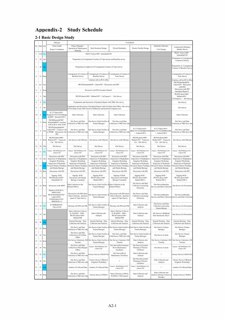
Appendix-2 Study Schedule
Officials
No. Date day Team Leader Project Manager / Hydraulic Structure/
Project Coordinator Operation & MaintenancePlanning Civil Design
1 5/28 Fri PK853 Tokyo1400→Islamabad2105
2 29 Sat Preparation of ConsignmentContract of Survey
3 30 Sun Preparation of ConsignmentContract of Baseline Survey
Consignment of Contract ofBaseline Survey
Consignment of Contract ofBaseline Survey
Consignment of Contract ofTopo Survey
Consignment of Contract ofTopo Survey
Courtesy call on JICA office
5 6/1 TuePK385Islamabad830→Lahore920、Discussion
with IPD
6 2 Wed Discussion with IPD(Inception Report)
7 3 ThuPK385Lahore1000→
Multan1055→CarTaunsa)、 Site Survey
8 4 Fri Site Survey
9 5 Sat Site Survey
10 6 SunJL717Tokyo1055→
Bangkok1555,CX701Bangkok2000→Karachi2220)
Data Collection Data Collection Data Collection Data Collection
11 7 MonPK300Karachi0700→
Islamabad0855, CourtesyCall to JICA, EOJ, EAD
Site Survy and DataCollection at TBD, Kot Adu
Site Survey (Gate Facility ofTaunsa Barrage)
Site Survy and DataCollection at TBD, Kot Adu
Site Survy and DataCollection at TBD, Kot Adu
12 8 Tue
PK385Islamabad830→Lahore920、Courtesy Callto PPDB、Discussion with
IPD
Site Survy and DataCollection at TBD, Kot Adu
Site Survey (Gate Facility ofTaunsa Barrage)
Site Survy and DataCollection at TBD, Kot Adu
JL717Tokyo1055→BKK1555,TG505BKK2000
→Lahore2240)
JL717Tokyo1055→BKK1555,TG505BKK2000
→Lahore2240)
Site Survy and DataCollection at TBD, Kot Adu
13 9 WedPK385Lahore1000→
Multan1055→Taunsa byCar、Site Survey
Site Survey with Officials Site Survey with Officials Site Survey with OfficialsPK385Lahore1000→
Multan1055→Taunsa byCar、Site Survey
PK385Lahore1000→Multan1055→Taunsa by
Car、Site SurveySite Survey with Officials
14 10 Thu Site Survey Site Survey Site Survey Site Survey Site Survey Site Survey Site Survey
15 11 Fri Taunsa→PK386Multan1145→Lahore1305
Taunsa→PK386Multan1145→Lahore1305
Taunsa→PK386Multan1145→Lahore1305
Taunsa→PK386Multan1145→Lahore1305
Taunsa→PK386Multan1145→Lahore1305
Taunsa→PK386Multan1145→Lahore1305
Taunsa→PK386Multan1145→Lahore1305
16 12 SatDiscussion with IPD、
Inspection of MoghalpuraIrrigation Workshop
Discussion with IPD、Inspection of Moghalpura
Irrigation Workshop
Discussion with IPD、Inspection of Moghalpura
Irrigation Workshop
Discussion with IPD、Inspection of Moghalpura
Irrigation Workshop
Discussion with IPD、Inspection of Moghalpura
Irrigation Workshop
Discussion with IPD、Inspection of Moghalpura
Irrigation Workshop
Discussion with IPD、Inspection of Moghalpura
Irrigation Workshop
17 13 SunInspection of Hydraulic
Research Station Nandipur,and Marala Barrage
Inspection of HydraulicResearch Station Nandipur,
and Marala Barrage
Inspection of HydraulicResearch Station Nandipur,
and Marala Barrage
Inspection of HydraulicResearch Station Nandipur,
and Marala Barrage
Inspection of HydraulicResearch Station Nandipur,
and Marala Barrage
Inspection of HydraulicResearch Station Nandipur,
and Marala Barrage
Inspection of HydraulicResearch Station Nandipur,
and Marala Barrage
18 14 Mon Discussion with IPD Discussion with IPD Discussion with IPD Discussion with IPD Discussion with IPD Discussion with IPD Discussion with IPD
19 15 TueSigning M/M,
PK388Lahore2020→Islamabad2110
Signing M/M,Discussion with Punjab
Barrage Consultant
Signing M/M、PK387Lahore1640→
Multan1800)
Signing of M/M,Discussion with Punjab
Barrage Consultant
Signing M/M、PK387Lahore1640→
Multan1800)
Signing M/M、PK387Lahore1640→
Multan1800)
Signing M/M、PK387Lahore1640→
Multan1800)
20 16 Wed Discussion with MWP Data Collection at theRelated Offices
Site Survey (Gate Facility ofTaunsa Barrage)
Data Collection at theRelated Offices
Site Survey and DataCollection concerning
Electricity
Site Survey(BaselineSurvey) and Data Collection Site Survey for Procurment
21 17 Thu
Report to EOJ,JICA、MWP,EAD、
PK381Islamabad1930→Lahore2020、
TG506Lahore2350→BKK0620(+1)
Discussion with IPD aboutData Collection, Interium
report of Topo-Survey
Site Survey (Gate Facility ofTaunsa Barrage)
Discussion with IPD aboutData Collection, Interium
report of Topo-Survey
Site Survey and DataCollection concerning
Electricity
Site Survey(BaselineSurvey) and Data Collection
Site Survey(BaselineSurvey) and Data Collection
22 18 Fri JL708BKK0830→Tokyo1610) Meeting with IPD and WB Site Survey (Gate Facility of
Taunsa Barrage) Meeting with IPD and WB Data Collection andAnalysis
Site Survey and DataCollection concerning
Taunsa BarrageSite Survey for Procurment
23 19 Sat
Data Collection(SurveyD,.WAPDA、IPD)、PK387Lahore1640→
Multan1800
Data Collection andAnalysis
Data Collection(SurveyD,.WAPDA、IPD)、PK387Lahore1640→
Multan1800
Data Collection andAnalysis
Site Survey(BulkheadGate Stockyard, Jetty) Site Survey for Procurment
24 20 Sun Internal Meeting、DataCollection and Analysis
Internal Meeting、DataCollection and Analysis
Internal Meeting、DataCollection and Analysis
Internal Meeting、DataCollection and Analysis
Internal Meeting、DataCollection and Analysis
Internal Meeting、DataCollection and Analysis
25 21 Mon Site Survy and DataCollection at TBD, Kot Adu
Site Survey (Gate Facility ofTaunsa Barrage)
Site Survey (Gate Facility ofTaunsa Barrage)
Site Survey (Gate Facility ofTaunsa Barrage)
Site Survey (TaunsaBarrage)
Site Survey (TaunsaBarrage)
26 22 TueSite Survy and Data
Collection at D.G.KhanOffice
Site Survey (Gate Facility ofTaunsa Barrage)
Site Survy and DataCollection at TBD, Kot Adu
Site Survey (Gate Facility ofTaunsa Barrage) Site Survey (Canal) Site Survey (Taunsa
Barrage)
27 23 Wed Site Survey (Upstream, HillTorrent)
Site Survey (Gate Facility ofTaunsa Barrage)
Site Survey (Upstream, HillTorrent)
Data Collection andAnalysis
Site Survey (Upstream, HillTorrent)
Site Survey (Upstream, HillTorrent)
28 24 ThuSite Survy and Data
Collection at MuzaffargahOffice
Taunsa→PK386Multan1145→Lahore1305
Site Survey(Environment,River Maintenance
Facilities)
Site Survey(LocationPlanning of Electric
Facilities)Site Survey (Canal) Taunsa→PK386Multan1145→
Lahore1305
29 25 Fri Site Survy and DataCollection at TBD, Kot Adu Factory Survey(DESCON) Site Survey(River
Maintenance Facilities)Data Collection and
Analysis 〃 Factory Survey(DESCON)
30 26 Sat Site Survy and DataCollection at TBD, Kot Adu
Factory Survey(BhalwalIrrigation Workshop) 〃
Site Survey(LocationPlanning of Electric
Facilities)
Data Collection andAnalysis
Factory Survey(BhalwalIrrigation Workshop)
31 27 Sun Analisis of Collected Data Analisis of Collected Data Taunsa→PK386Multan1145→Lahore1305
Taunsa→PK386Multan1145→Lahore1305 〃 Analisis of Collected Data
32 28 Mon Site Survy and DataCollection at TBD, Kot Adu Factory Survey(PEKO) Data Collection at IPD &
WAPDA(TM System)Data Collection and
Analysis
Data Collection andAnalysis (Design Criteria of
Barrage)Factory Survey(PEKO)
2-1 Basic Design Study
Explanation and discussion of Inception Report with TBD, Site survey
Explanation and discussion of Inception Report with D.G.khan Zone Office, Site surveyof D.G.Khan Canal, Hill Torrent of Mithawan and beneficial irrigation area.
Consultants
4 31 Mon
Courtesy call on JICA office
PK385Islamabad830→Lahore920、Discussion with IPD
Preparation of Approval of Consignment Contract of Topo-survey
Discussion with IPD (Inception Report)
Steel Structure Design Construction Planning/Quality Survey
Preparation of Consignment Contract of Topo-survey and Baseline survey
Fluvial Hydraulics Electric Facility Design
PK853 Tokyo1400→Islamabad2105
PK385Lahore1000→Multan1055→CarTaunsa)、 Site Survey
A2-1

Officials
No. Date day Team Leader Project Manager / Hydraulic Structure/
Project Coordinator Operation & MaintenancePlanning Civil Design
Consultants
Steel Structure Design Construction Planning/Quality SurveyFluvial Hydraulics Electric Facility Design
33 29 TueSite Survy and Data
Collection at D.G.KhanOffice
Analisis of Collected Data Environmental Survey(Library、EPD)
Data Collection andMarketing Survey ofElectrical Equipment
Data Collection andAnalysis (Design Criteria of
Barrage)
Data Collection of BaselineSurvey
34 30 Wed Inspection ofChashima/Jinnah Barrages
Inspection ofChashima/Jinnah Barrages
Inspection ofChashima/Jinnah Barrages
Inspection ofChashima/Jinnah Barrages
Inspection ofChashima/Jinnah Barrages
Inspection ofChashima/Jinnah Barrages
35 7/1 Thu Site Survy and DataCollection at TBD, Kot Adu
Inspection of TrimmuBarrage
PK390Lahore1340→
Islamabad1430)
Data Collection andMarketing Survey ofElectrical Equipment
Analisis of Collected DataData Collection andMarketing Survey ofElectrical Equipment
36 2 Fri Site Survy and DataCollection at TBD, Kot Adu Analisis of Collected Data
Data Collection at SurveyDepart. and Depart.of
StatisticAnalisis of Collected Data Evaluation and Receiving of
Baseline Survey ResultData Collection for Cost
Estimation & Procurment
37 3 Sat PK386Multan1145→Lahore1240)
Discussion with IPD(Design of Gate,
Procurement)
Data Analysis,PK381Islamabad1930→
Lahore2020Analisis of Collected Data PK386Multan1145→
Lahore1240)
Survey at IPD(Cost Estimation ・
Procurement)
38 4 Sun Analisis of Collected Data& Internal Meeting
Analisis of Collected Data& Internal Meeting
Analisis of Collected Data& Internal Meeting
Analisis of Collected Data& Internal Meeting
Analisis of Collected Data& Internal Meeting
Analisis of Collected Data& Internal Meeting
39 5 MonDiscussion with IPD (Works
done by Pakistan &Budgetary Plan)
PK315raho-ru0830→Karachi1015→
(Car)haiderabad)、KotriBarrage→(Car)Karachi,PK305karachi1900→
Lahore2045)
Preparation of SummaryReport of the Site Survey
Preparation of SummaryReport of the Site Survey
PK315raho-ru0830→Karachi1015→
(Car)haiderabad)、KotriBarrage→(Car)Karachi,PK305karachi1900→
Lahore2045)
Discussion withIPD(Budgetary Plan, Work
Costs borne by IPD)
40 6 Tue Discussion with IPD Discussion with IPD Discussion with IPD TG506Lahore2350→BKK0620(+1))
Preparation of SummaryReport of the Site Survey
Data Collection at RelevantOffice for Cost Estimation
41 7 Wed Report and Discussion withIPD
Report and Discussion withIPD
Report and Discussion withIPD
JL708BKK0830→Tokyo1610
Report and Discussion withIPD
Report and Discussion withIPD
42 8 Thu
Report and Discussion withIPD 、Inspection &
Receiving of Topo surveyresult
Report and Discussion withIPD 、Data Collection at
Relevant Office forConstruction Planning
43 9 Fri Analisis of Collected Data 〃
44 10 Sat 〃 〃
45 11 Sun 〃 Analisis of Collected Data
46 12 Mon 〃Data Collection at RelevantOffice for Construction
Planning
47 13 Tue Preparation of SummaryReport of the Site Survey
Preparation of SummaryReport of the Site Survey
48 14 Wed 〃 〃
49 15 Thu 〃 〃
50 16 Fri 〃 〃
51 17 Sat
52 18 Sun
53 19 Mon TG774BKK0820→Osaka1530)
JL708BKK0830→Tokyo1610
2-2 Explanation of the Draft Basic Design Study ReportOfficials
No. Date day Team Leader Project Manager / Hydraulic Structure/
Project Coordinator Operation & MaintenancePlanning Civil Design
1 9/14 TueJL5113Osaka1145→
BKK1535,TG505BKK2000→Lahore2240)
JL717Tokyo1100→BKK1530,TG505BKK2000
→Lahore2240
JL5113Osaka1145→BKK1535,TG505BKK2000
→Lahore2240)
2 15 WedExplanation and discussionwith IPD on the Draft Basic
Design Report
3 16 ThuExplanation and discussionwith IPD on the Draft Basic
Design Report
4 17 FriExplanation and discussionwith IPD on the Draft Basic
Design Report
5 18 SatExplanation and discussionwith IPD on the Draft Basic
Design Report
6 19 SunPK387Islamabad1410→Lahore1500)、Intenal
Meeting
Data Analysis,InternalMeeting
Data Analysis,InternalMeeting
Data Analysis,InternalMeeting
7 20 Mon
Corutesy Call to PPDB、Explanation and discussionwith IPD on the Draft Basic
Design Report
8 21 TueExplanation and discussionwith IPD on the Draft Basic
Design Report
Discussion with IPD、
Signing M/M、
PK386Lahore1340→Islamabad1430 Discussion with IPD
Discussion with IPD
PK388Lahore2020→Islamabad2110)
Data Analysis Data Analysis
TG506Lahore2350→BKK0620(+1))
TG506Lahore2350→BKK0620(+1))
12 25 Sat JL708BKK0830→Tokyo1610
JL728BKK0910→Osaka1635
JL708BKK0830→Tokyo1610)
JL728BKK0910→Osaka1635
Discussion with IPD
11 24 Fri
Report to EOJ,JICA、
PK381Islamabad1930→Lahore2020、TG506Lahore2350→BKK0620(+1))
10 23 THu Discussion with EAD andMWP
9 22 Wed
Discussion with IPD、Signing M/M、
Discussion with IPD
Discussion with IPD
Explanation and discussion with IPD on the Draft BasicDesign Report
Explanation and discussion with IPD on the Draft BasicDesign Report
Corutesy Call to PPDB、Explanation and discussion with IPD on the Draft BasicDesign Report
Explanation and discussion with IPD on the Draft Basic Design Report
Explanation and discussion with IPD on the Draft BasicDesign Report
Explanation and discussion with IPD on the Draft BasicDesign Report
Report to JICA、
JL708BKK0835→Tokyo1635
Factory Survey(HMC)、PK369Islamabad1705→Karachi1900)TG502Karachi2330→BKK0630(+1))
Report and Discussion with IPD IPDPK390Lahore1625→Islamabad1715
Construction Planning/Quality Survey
Consultants
Steel Structure Design Fluvial Hydraulics Electric Facility Design
TG506Lahore2350→BKK0620(+1))
Report and Discussion with IPD
A2-2

A3-1
Appendix-3 List of Parties Concerned in the Government of Pakistan
Name Position
Irrigation and Power Department (IPD), Government of Punjab (GOP)
Javed Majid Secretary, IPD, GOP
Asrar-ul-Haq Additional Secretary (Technical), IPD, GOP
Zaka Ullah Bhatti Chief Engineer, Irrigation Development Zone, IPD, GOP
Ehsan Ullah Sardar Chief Engineer, Research Zone, IPD, GOP
Rao Mohammad Riaz Director Regulation, IPD, GOP
A. Sattar Malik Superintending Engineer, IPD, GOP
Mian Javaid Mechanical Engineer, Moghalpura Irrigation Workshop (MIW), IPD, GOP
Riazul Haq Assistant Engineer MIW, IPD, GOP
Tariq Rauf Qureshi Executive Engineer, Bharwal Irrigation Workshop (BIW), IPD, GOP
Prof. Ghulam Qadir Irrigation Research Institute, IPD, GOP
M. Younis Ansari Senior Engineer, Mechanical Circle Lahore, IPD, GOP
Mahmood Ahmad Awan Assistant Design Engineer, Department Zone, IPD, GOP
Amjad Saeed Executive Engineer, Marala Barrage Division, IPD, GOP
Naveed Alam Sub Division Officer, Jinnah Barrage, Kalabagh Division, Thal Canal Circle, Sargodha Irrigation Zone, IPD, GOP
Waqar Khan Chief Engineer, Lahore Zone, IPD, GOP
Muhammad Saeed Superintending Engineer, U.C.C.Link Circle
Irrigation D. G. Khan Zone, IPD, GOP
Dr. Bagh Ali Shahid Chief Engineer, Irrigation D. G. Khan Zone
Masud Anwar Chughtai Executive Engineer, Irrigation D. G. Khan Zone
Rafif Ansari Divisional Head Draftsman, Irrigation D. G. Khan Zone
Muzaffargarh Canal Division, Irrigation D. G. Khan Zone, IPD, GOP
Ch. Muhammad Aslam Sub Division Officer, Muzaffargarh Canal Division
Taunsa Barrage Division (TBD), Irrigation D. G. Khan Zone, IPD, GOP
Mehr Muhammad Amin Executive Engineer, TBD
Rana Muhammad Afzal Assistant Executive Engineer, TBD
Chudrie Afzal Sub-Engineer (Hydraulics), Head Works Sub Division, TBD
Inayat Ullah Shah Sub Engineer, Head Works Sub Division, TBD
Shahid Hassan Head Draftsman, TBD
M. Maghas Bhutta Computer Operator, TBD

A3-2
Name Position
Muhammad Muneer Anjum Sub Divisional Officer, Workshop Sub Division, TBD
Malik Khadin Hussain Sub Division Officer, Bund Sub Division, TBD
Saleem Bhaffi Sub Engineer, Left Marginal Bank (1), Head Works Sub Division, TBD
Other Organization Concerned in Lahore
Muhammad Ahsan Raja Secretary, Planning and Development Department (PDD), GOP
Wasif Sultan Ali Khan Chief of Water and Power, Planning and Development Department, Lahore, GOP
Chaudhry Ahmad Nadeem Deputy Director (EIA), Environment Protection Department
Abdur Rabbani Qureshi Director of Water Resources Management Directorate (room No. 227), WAPDA home, Lahore
Jawed Iqbal Bhatti Executive Engineer, Maintenance and Communication Division, Hydrology Research Directorate, WAPDA
Muhammad Riaz Director of RNC, Pakistan Meteorological Department, Lahore
Shar Muhammad Assistant Director, Survey of Pakistan, Lahore
Syed Mansoob Ali Zaidi Project Manager, Punjab Barrage Consultants
Shamsher Khan Bhatti Principal Mechanical Engineer, Punjab Barrage Consultants
Other Organization Concerned in Multan
Avid Hussan Buzdar Assistant Manager, MEPCO(Multan Electric Power Co.)
Ch. Mond Sabir Electric Inspector, Multan, WAPDA
Other Organization Concerned in Islamabad
Mahjabeen A. Hamid Planning Coordination Section, Planning and Development Division, Ministry of Planning and Development
World Bank Mission
Xiaokai Li Senior Water Resources Specialist, Rural Development Sector Unit, South Asia Region
William T. Smith Consultant, Land and Water Resources
Punjab Barrage Consultants
Syed Mansoob Ali Zaidi Project Manager
Shamsher Khan Bhatti Mechanical Engineer

A4-1
Appendix 4. Minutes of Discussion
4-1 Basic Design Study ................................................................................................................. A4-2
4-2 Explanation of the Draft Basic Design Report...................................................................... A4-13


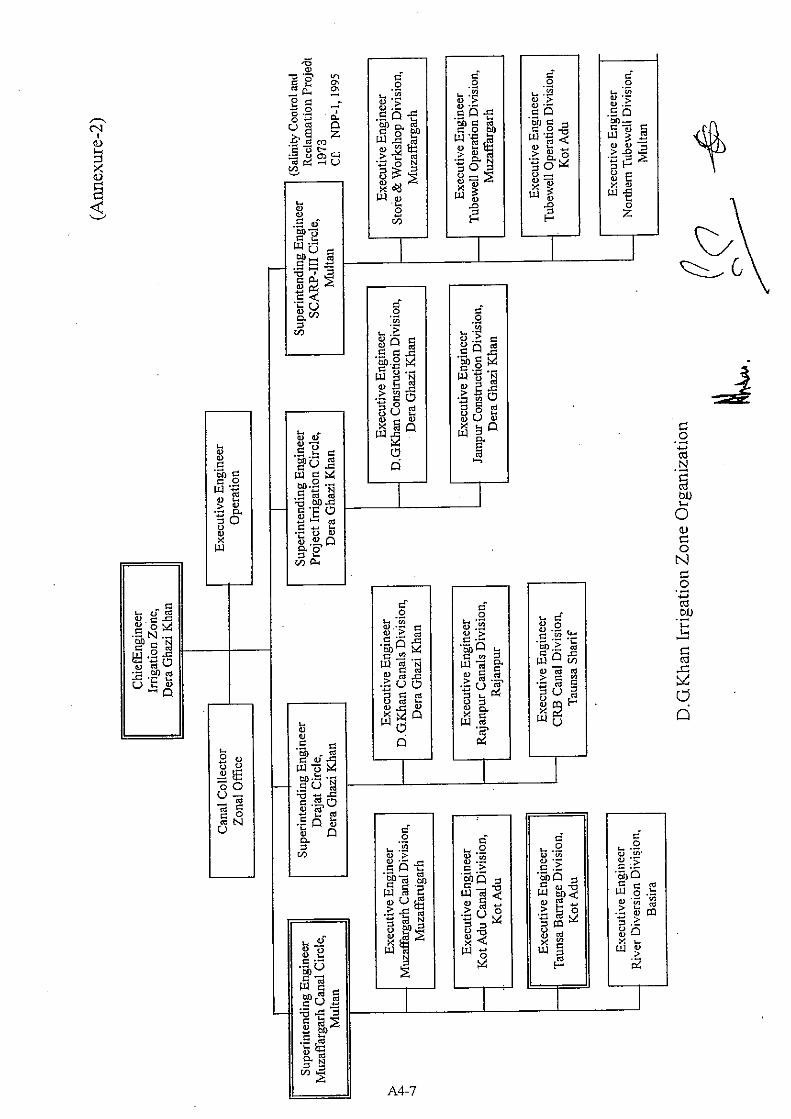


App
endi
x-5
List
of D
ata
Col
lect
ed
No.
N
ame
Form
O
rigin
al /
Cop
y Pu
blis
her
Year
1 ST
ATEM
ENT
SHO
WIN
G Y
EAR
WIS
E SE
RIO
US
DA
MA
GES
AT
TAU
NSA
BA
RR
AG
E Pa
per
Cop
y IP
D, T
AU
NSA
Bar
rage
Div
isio
n
Offi
ce
2 A
BR
IEF
NO
TE O
N F
AN
MA
NA
GEM
ENT
OF
MIT
HAW
AN
HIL
L
TOR
REN
T IN
D.G
.KH
AN
DIS
TRIC
T B
ook
Orig
inal
D
.G.K
HA
N Ir
rigat
ion
offic
e
3 Pr
esen
tatio
n to
Pa
kist
an
Dev
elop
men
t Fo
rum
“I
nfra
stru
ctur
e fo
r
Acc
eler
ated
Gro
wth
” M
arch
17
– 19
, 200
4
Wat
er S
ecto
r Im
prov
emen
t Pr
ogra
mm
e in
Sin
dh B
y C
hairm
an, S
indh
Irrig
atio
n &
Dra
inag
e Aut
horit
y
Pape
r C
opy
JIC
A P
akis
tan
Offi
ce
4
PC -
1 PR
OFP
RM
A
PUN
JAB
BA
RR
AG
E R
EHA
BIL
ITAT
ION
AN
D M
OD
ERN
IZAT
ION
PRO
JEC
T V
OLU
M-1
Pape
r C
opy
IPD
, Pum
jab
(JIC
A P
akis
tan
Offi
ce)
May
, 200
3
5
PC-1
PR
OFP
RM
A
TAU
NSA
B
AR
RA
GE
IRR
IGAT
ION
SY
STEM
R
EHA
BIL
ITA
ION
PRO
JEC
T
Pape
r C
opy
IPD
, Pum
jab
(JIC
A P
akis
tan
Offi
ce)
Aug
ust,
2002
6
PRES
ENTA
TIO
N O
N W
ATER
SEC
TOR
PR
OG
RA
M N
.W.F
.P B
Y
MU
HA
MM
AD
SH
EHZA
D A
RB
AB
SEC
RET
ARY
IR
RIG
ATIO
N &
POW
ER D
EPA
RTM
ENT
Pape
r C
opy
JIC
A P
akis
tan
Offi
ce
7 PA
KIS
TAN
DEV
ELO
PMEN
T FO
RU
M
WAT
ER S
ECTO
R: D
EVEL
OPM
ENT
STR
ATEG
IES
Pape
r C
opy
IPD
, Pum
jab
(JIC
A P
akis
tan
Offi
ce)
A5-1
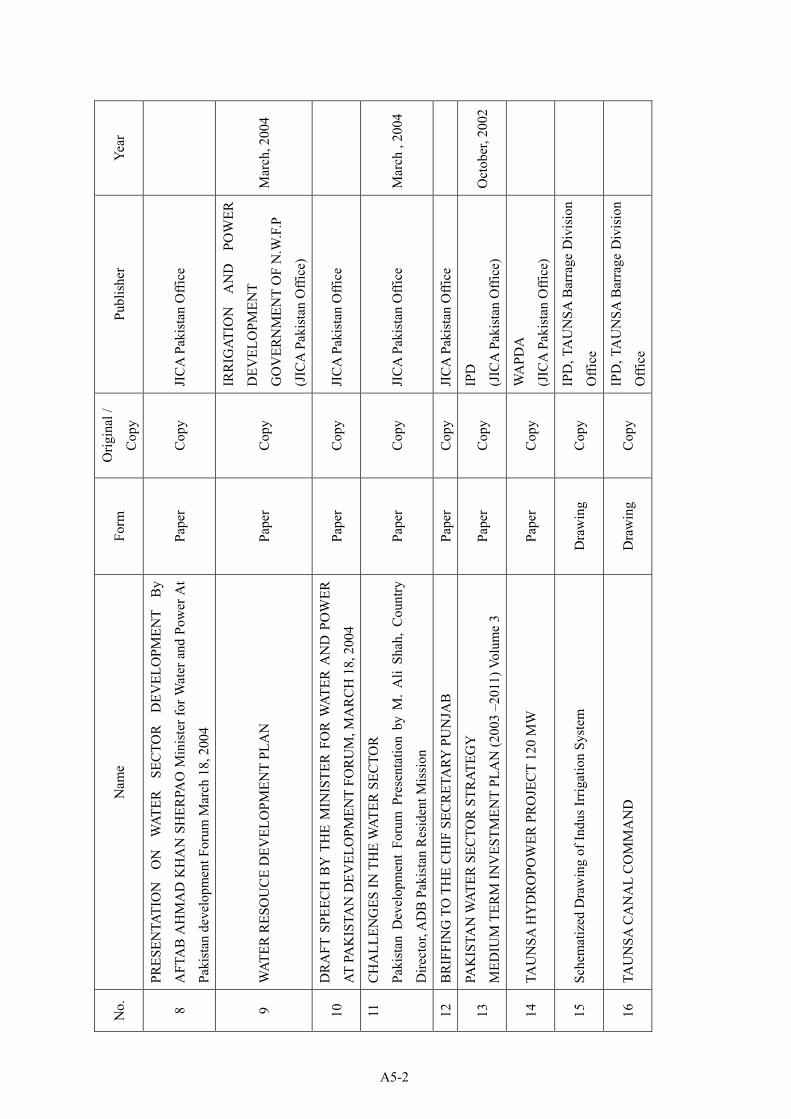
No.
N
ame
Form
O
rigin
al /
Cop
y Pu
blis
her
Year
8
PRES
ENTA
TIO
N
ON
W
ATER
SE
CTO
R
DEV
ELO
PMEN
T B
y
AFT
AB
AH
MA
D K
HA
N S
HER
PAO
Min
iste
r for
Wat
er a
nd P
ower
At
Paki
stan
dev
elop
men
t For
um M
arch
18,
200
4
Pape
r C
opy
JIC
A P
akis
tan
Offi
ce
9 W
ATER
RES
OU
CE
DEV
ELO
PMEN
T PL
AN
Pa
per
Cop
y
IRR
IGAT
ION
A
ND
PO
WER
DEV
ELO
PMEN
T
GO
VER
NM
ENT
OF
N.W
.F.P
(JIC
A P
akis
tan
Offi
ce)
Mar
ch, 2
004
10
DR
AFT
SPE
ECH
BY
TH
E M
INIS
TER
FO
R W
ATER
AN
D P
OW
ER
AT P
AK
ISTA
N D
EVEL
OPM
ENT
FOR
UM
, MA
RC
H 1
8, 2
004
Pape
r C
opy
JIC
A P
akis
tan
Offi
ce
11
CH
ALL
ENG
ES IN
TH
E W
ATER
SEC
TOR
Paki
stan
Dev
elop
men
t Fo
rum
Pre
sent
atio
n by
M.
Ali
Shah
, C
ount
ry
Dire
ctor
, AD
B P
akis
tan
Res
iden
t Mis
sion
Pape
r C
opy
JIC
A P
akis
tan
Offi
ce
Mar
ch ,
2004
12
BR
IFFI
NG
TO
TH
E C
HIF
SEC
RET
ARY
PU
NJA
B
Pape
r C
opy
JIC
A P
akis
tan
Offi
ce
13
PAK
ISTA
N W
ATER
SEC
TOR
STR
ATEG
Y
MED
IUM
TER
M IN
VES
TMEN
T PL
AN
(200
3 –2
011)
Vol
ume
3 Pa
per
Cop
y IP
D
(JIC
A P
akis
tan
Offi
ce)
Oct
ober
, 200
2
14
TAU
NSA
HY
DR
OPO
WER
PR
OJE
CT
120
MW
Pa
per
Cop
y W
APD
A
(JIC
A P
akis
tan
Offi
ce)
15
Sche
mat
ized
Dra
win
g of
Indu
s Irr
igat
ion
Syst
em
Dra
win
g C
opy
IPD
, TA
UN
SA B
arra
ge D
ivis
ion
Offi
ce
16
TAU
NSA
CA
NA
L C
OM
MA
ND
D
raw
ing
Cop
y IP
D, T
AU
NSA
Bar
rage
Div
isio
n
Offi
ce
A5-2
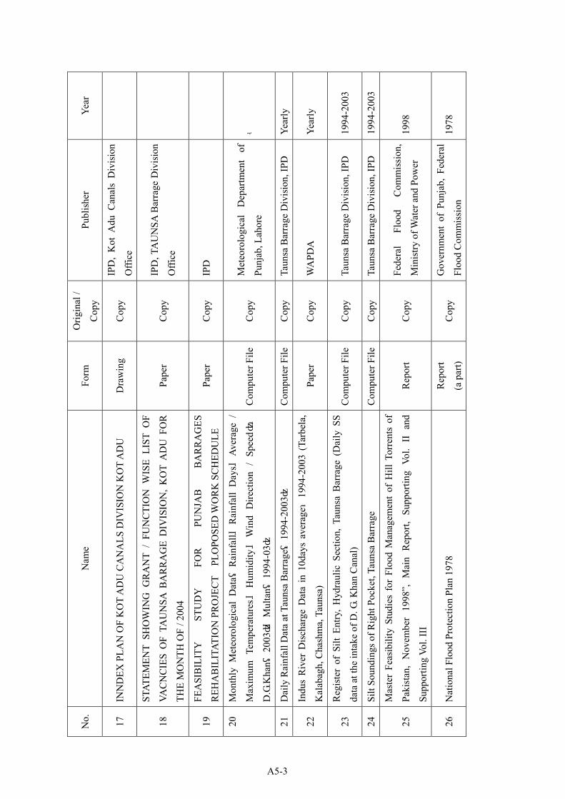
No.
N
ame
Form
O
rigin
al /
Cop
y Pu
blis
her
Year
17
INN
DEX
PLA
N O
F K
OT
AD
U C
AN
ALS
DIV
ISIO
N K
OT
AD
U
Dra
win
g C
opy
IPD
, K
ot A
du C
anal
s D
ivis
ion
Offi
ce
18
STAT
EMEN
T SH
OW
ING
GR
AN
T /
FUN
CTI
ON
WIS
E LI
ST O
F
VAC
NC
IES
OF
TAU
NSA
BA
RR
AG
E D
IVIS
ION
, K
OT
AD
U F
OR
THE
MO
NTH
OF
/ 200
4
Pape
r C
opy
IPD
, TA
UN
SA B
arra
ge D
ivis
ion
Offi
ce
19
FEA
SIB
ILIT
Y
STU
DY
FO
R
PUN
JAB
B
AR
RA
GES
REH
AB
ILIT
ATIO
N P
RO
JEC
T P
LOPO
SED
WO
RK
SC
HED
ULE
Pa
per
Cop
y IP
D
20
Mon
thly
Met
eoro
logi
cal
Dat
a(R
ainf
all、
Rai
nfal
l D
ays、
Aver
age
/
Max
imum
Tem
pera
ture
s、H
umid
ity、
Win
d D
irect
ion
/ Sp
eed):
D.G
.Kha
n(20
03)、
Mul
tan(
1994
-03)
Com
pute
r File
C
opy
Met
eoro
logi
cal
Dep
artm
ent
of
Punj
ab, L
ahor
e -
21
Dai
ly R
ainf
all D
ata
at T
auns
a B
arra
ge(
1994
-200
3)
Com
pute
r File
C
opy
Taun
sa B
arra
ge D
ivis
ion,
IPD
Ye
arly
22
Indu
s R
iver
Dis
char
ge D
ata
in 1
0day
s av
erag
e:19
94-2
003
(Tar
bela
,
Kal
abag
h, C
hash
ma,
Tau
nsa)
Pa
per
Cop
y W
APD
A
Year
ly
23
Reg
iste
r of
Silt
Ent
ry,
Hyd
raul
ic S
ectio
n, T
auns
a B
arra
ge (
Dai
ly S
S
data
at t
he in
take
of D
. G. K
han
Can
al)
Com
pute
r File
C
opy
Taun
sa B
arra
ge D
ivis
ion,
IPD
19
94-2
003
24
Silt
Soun
ding
s of R
ight
Poc
ket,
Taun
sa B
arra
ge
Com
pute
r File
C
opy
Taun
sa B
arra
ge D
ivis
ion,
IPD
19
94-2
003
25
Mas
ter
Feas
ibili
ty S
tudi
es f
or F
lood
Man
agem
ent
of H
ill T
orre
nts
of
Paki
stan
, N
ovem
ber
1998
”, M
ain
Rep
ort,
Supp
ortin
g Vo
l. II
and
Supp
ortin
g Vo
l. II
I
Rep
ort
Cop
y Fe
dera
l Fl
ood
Com
mis
sion
,
Min
istry
of W
ater
and
Pow
er
1998
26
Nat
iona
l Flo
od P
rote
ctio
n Pl
an 1
978
Rep
ort
(a p
art)
Cop
y G
over
nmen
t of
Pun
jab,
Fed
eral
Floo
d C
omm
issi
on
1978
A5-3
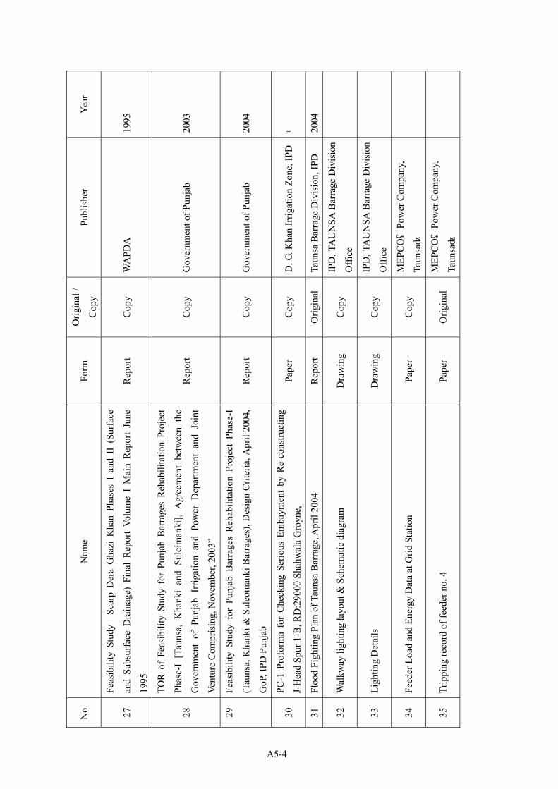
No.
N
ame
Form
O
rigin
al /
Cop
y Pu
blis
her
Year
27
Feas
ibili
ty S
tudy
Sc
arp
Der
a G
hazi
Kha
n Ph
ases
I a
nd I
I (S
urfa
ce
and
Subs
urfa
ce D
rain
age)
Fin
al R
epor
t Vo
lum
e I
Mai
n R
epor
t Ju
ne
1995
Rep
ort
Cop
y W
APD
A
1995
28
TOR
of
Feas
ibili
ty S
tudy
for
Pun
jab
Bar
rage
s R
ehab
ilita
tion
Proj
ect
Phas
e-I
[Tau
nsa,
Kha
nki
and
Sule
iman
ki],
Agr
eem
ent
betw
een
the
Gov
ernm
ent
of P
unja
b Ir
rigat
ion
and
Pow
er D
epar
tmen
t an
d Jo
int
Vent
ure
Com
pris
ing,
Nov
embe
r, 20
03”
Rep
ort
Cop
y G
over
nmen
t of P
unja
b 20
03
29
Feas
ibili
ty S
tudy
for
Pun
jab
Bar
rage
s R
ehab
ilita
tion
Proj
ect
Phas
e-I
(Tau
nsa,
Kha
nki &
Sul
eom
anki
Bar
rage
s), D
esig
n C
riter
ia, A
pril
2004
,
GoP
, IPD
Pun
jab
Rep
ort
Cop
y G
over
nmen
t of P
unja
b 20
04
30
PC-1
Pro
form
a fo
r C
heck
ing
Serio
us E
mba
ymen
t by
Re-
cons
truct
ing
J-H
ead
Spur
1-B
, RD
:290
00 S
hahw
ala
Gro
yne,
Pa
per
Cop
y D
. G. K
han
Irrig
atio
n Zo
ne, I
PD-
31
Floo
d Fi
ghtin
g Pl
an o
f Tau
nsa
Bar
rage
, Apr
il 20
04
Rep
ort
Orig
inal
Ta
unsa
Bar
rage
Div
isio
n, IP
D
2004
32
Wal
kway
ligh
ting
layo
ut &
Sch
emat
ic d
iagr
am
Dra
win
g C
opy
IPD
, TA
UN
SA B
arra
ge D
ivis
ion
Offi
ce
33
Ligh
ting
Det
ails
D
raw
ing
Cop
y IP
D, T
AU
NSA
Bar
rage
Div
isio
n
Offi
ce
34
Feed
er L
oad
and
Ener
gy D
ata
at G
rid S
tatio
n Pa
per
Cop
y M
EPC
O(
Pow
er C
ompa
ny,
Taun
sa)
35
Trip
ping
reco
rd o
f fee
der n
o. 4
Pa
per
Orig
inal
M
EPC
O(
Pow
er C
ompa
ny,
Taun
sa)
A5-4

No.
N
ame
Form
O
rigin
al /
Cop
y Pu
blis
her
Year
36
Feed
er D
eman
d D
ata
Pape
r C
opy
MEP
CO(
Pow
er C
ompa
ny,
Taun
sa)
37
Sing
le L
ine
diag
ram
of 1
1kV
feed
er N
o.4
Pape
r C
opy
MEP
CO(
Pow
er C
ompa
ny,
Taun
sa)
38
Site
Pla
n of
Bel
dar’s
Qua
rters
at T
auns
a B
arra
ge
Pape
r C
opy
IPD
, TA
UN
SA B
arra
ge D
ivis
ion
Offi
ce
39
Tech
nica
l Dat
a of
Fee
ders
Pa
per
Cop
y M
EPC
O(
Pow
er C
ompa
ny,
Taun
sa)
40
Bas
e m
ap o
f 11k
V T
/wel
l fee
der N
o.4
Pa
per
Cop
y M
EPC
O(
Pow
er C
ompa
ny,
Taun
sa)
41
Har
d-co
py o
n di
spla
y on
Tel
e-m
eter
ing
syst
em
Pape
r C
opy
Siem
ens (
Taun
sa)
42
Tarif
f Rat
e (h
and
writ
ing
mem
o)&
Ele
ctric
ity C
onsu
mer
Bill
Pa
per
Cop
y M
EPC
O(
Pow
er C
ompa
ny,
Taun
sa)
43
Stan
dard
ized
Spe
cific
atio
n of
Sto
res
Pape
r C
opy
IPD
, MIW
44
TER
MS
OF
REF
EREN
CE
of
AG
REE
MEN
T (A
NN
EXR
E-B
),
Feas
ibili
ty S
tudy
for
Pun
jab
Bar
rage
s R
ehab
ilita
tion
Proj
ect
Phas
e-1
(Tau
nsa,
Kha
nki a
nd S
ulem
anki
)
Pape
r C
opy
IPD
45
Lette
r of A
ppro
val o
f “TA
UN
SA B
AR
RA
GE
IRR
IGAT
ION
SY
STEM
REH
AB
ILIT
ATIO
N P
RO
JEC
T” a
ppro
ved
by t
he E
CN
EC M
eetin
g
held
on
23.0
4.20
03
Pape
r C
opy
JIC
A
A5-5

No.
N
ame
Form
O
rigin
al /
Cop
y Pu
blis
her
Year
46
Min
ute
of t
he E
XEC
UTI
VE
CO
MM
ITTE
E O
F TH
E N
ATIO
NA
L
ECO
NO
MIC
C
OU
NC
IL
MEE
TIN
G
HEL
D
ON
7.
1.20
04,
AT
ISLA
MA
BA
D in
clud
ing
DEC
ISIO
N o
f “Pu
njab
Bar
rage
Reh
abili
tatio
n
and
Mod
erni
zatio
n Pr
ojec
t”
Pape
r C
opy
IPD
47
-ditt
o-
Pape
r C
opy
JIC
A
48
Brie
f on
Punj
ab Ir
rigat
ion
& P
ower
Dep
artm
ent,
Oct
ober
200
3 Pa
per
Cop
y IP
D
49
IPD
Exp
endi
ture
199
7/98
to 2
001/
02
Pape
r C
opy
IPD
50
TEN
Y
EAR
PR
OSP
ECTI
VE
DEV
ELO
PMEN
T PL
AN
2001
-11(
Exce
rptio
n)
Pape
r C
opy
PDD
51
Org
aniz
atio
n C
hart
of B
urea
u of
Sta
tistic
s Pun
jab
Pape
r C
opy
Bur
eau
of S
tatis
tics P
unja
b
52
Feas
ibili
ty S
tudy
SC
AR
P D
ERA
GH
AZI
KH
AN
Pha
se I
and
II,
Fina
l
Rep
ort (
Mai
n &
Ann
exes
) *
Boo
k C
opy
D.G
.Kha
n Zo
ne O
ffice
53
Feas
ibili
ty
Rep
ort
Con
trol
of
Wat
erlo
ggin
g H
azar
ds
in
MU
ZAFF
AR
GA
RH
CA
NA
L C
OM
MA
ND
, Fi
nal
Rep
ort
(Mai
n &
Ann
exes
) *
Boo
k C
opy
D.G
.Kha
n Zo
ne O
ffice
54
Feas
ibili
ty S
tudy
for
Pun
jab
Bar
rage
s R
ehab
ilita
tion
Proj
ect P
hase
–1
(Tau
nsa,
Kha
nki &
Sul
eim
anki
Bar
rage
s) V
olum
e I –
Mai
n R
epor
t C
D
Cop
y Pu
njab
Bar
rage
Con
sulta
nt
2004
.7
55
Feas
ibili
ty S
tudy
for
Pun
jab
Bar
rage
s R
ehab
ilita
tion
Proj
ect P
hase
–1
(Tau
nsa,
Kha
nki &
Sul
eim
anki
Bar
rage
s) V
olum
e II
– A
ppen
dixe
s C
D
Cop
y Pu
njab
Bar
rage
Con
sulta
nt
2004
.7
A5-6
A6-1
Appendix-6 Other Relevant Data and Information
A6-1 Cost Estimation borne by the Recipient Country ...........................................................A6-1.1
A6-2 Economic Analysis of Bulkhead Gate Numbers ............................................................A6-2.1
A6-3 Structural Calculation of the Under Sluice Gate ............................................................A6-3.1
A6-4 Structural Calculation of the Weir Gate..........................................................................A6-4.1
A6-5 Structural Calculation of the Bulkhead Gate ..................................................................A6-5.1
A6-6 Structural Reinforcement calculation of Existing Deck Frame ......................................A6-6.1
A6-7 Incline Design Calculation in the Bulkhead Gate Stockyard .........................................A6-7.1
A6-8 Capacity Calculation of Emergency Generator for Gate Operation ...............................A6-8.1
A6-9 Capacity Calculation of Generator for Winch in the Bulkhead Gate Stockyard ............A6-9.1
A6-10 Figures for Construction Manner .................................................................................A6-10.1

= ¥1.9
Unit Cost Amount Conversion toYen
(1000 Rs) (1000 Rs) (Million Yen)
1) Embankment of the Stockyardfor Bulkhead Gate lot 1.0 14,809 14,809 28.1
2) Construct Fence aroundStockyard for Bulkhead lot 1.0 258 258 0.5
3) Removal of Telemeter Panel lot 1.0 353 353 0.7
4) Bank Service Chargeslot 1.0 78,316 78,316 148.8
Total 93,736 178.1
A6-1. Cost Estimation born by the Recipient Country
RemarksItem Unit Q'ty
3% of grantaid project
cost
A6-1.1

(Rs) (Rs)Reclaim of the Stockyard for Burlkhead Gate
Direct cost m3 100,500Excavation soil for m3 111,667 24 2,680,001 5,092,002 Unit cost No 3-4Hauling soil about 10km m3 111,667 42 4,690,001 8,911,002 Unit cost No 1-2Embankment m3 100,500 12 1,206,000 2,291,400 Unit cost No 3-25Saping the slope m2 9,000 1 9,000 17,100 Unit cost No 3-19
Sub total 8,585,002 16,311,504
Overhead Cost & others (50% of direct cost) 4,292,501 8,155,752
Total Round by 1000Rs 12,877,000
TAX 15% 1,931,550
Grand Total 110.0 \/$ 14,808,550 28,136,2451.9 \/R
(Rs) (Rs)Construction of Fence around Stockyard for Bulkhead Gate
m 370Fence (H=1.8m) m 370 216 79,920 151,848 Unit cost No 25-50Gate of fence(W=2m×2) no 2 34,919 69,838 132,692 Unit cost No 25-31
Sub total 149,758 284,540
Overhead Cost & others (50% of direct cost) 74,879 142,270
Total Round by 1000Rs 224,000 425,600
TAX 15% 33,600 63,840
Grand Total 110.0 \/$ 257,600 489,4401.9 \/R
unitItem
unitItem Remarks
RemarksAmountAmountUnit Cost
AmountAmountUnit Cost Convert into
Yen (JY)
Convert intoYen (JY)
A6-1.2

(Rs) (Rs)Removal of Telemeter Panel
place 9Remove panel place 9 12,100 108,900 206,910Remove cable place 9 2,100 18,900 35,910Remove cable rack place 9 5,300 47,700 90,630Remove pullbox place 9 3,300 29,700 56,430
Sub total 205,200 389,880
Overhead Cost & others (50% of direct cost) 102,600 194,940
Total Round by 1000Rs 307,000 583,300TAX 15% 46,050 87,495
Grand Total 110.0 \/$ 353,050 670,795
(Rs) (Rs)Remove panel place 1Replace Piece 1
Electric Engineer man-day 0.8 3,000 2,400 4,560Electrician man-day 2.2 1,000 2,200 4,180
Setting Electric Engineer man-day 1.3 3,000 3,900 7,410Electrician man-day 3.6 1,000 3,600 6,840
Total 12,100 22,990
Remove cable place 1Replace m 4
Electrician man-day 0.3 3,000 900 1,710Setting
Electrician man-day 0.4 3,000 1,200 2,280
Total 2,100 3,990
Remove cable rack place 1Replace m 4
Electrician man-day 0.6 3,000 1,800 3,420Setting
Electrician man-day 0.9 3,000 2,700 5,130Cable m 4 200.00 800 1,520
Total 5,300 10,070
Remove pullbox place 1Replace piece 2
Electrician man-day 0.4 3,000 1,200 2,280Setting
Electrician man-day 0.7 3,000 2,100 3,990
Total 3,300 6,270
Remarks
Item Remarks
Convert intoYen (JY)
Convert intoYen (JY)
AmountAmount Unit Cost
Amount Unit Cost Amount
unitItem
unit
A6-1.3

1
BHG Investment TotalNo. Cost (M.Rs) 29 units 36 units 65 units
(Grant.A.P) (Punj. P)4 units 118.00 2.5 yr 4.5 yr 7 yr
5 units 143.00 2 yr 2.5 yr 4.5 yr
6 units 174.00 2 yr 2.5 yr 4.5 yr
7 units 205.00 1.5 yr 2 yr 3.5 yr
2 Investment Cost (Million Rs.) Ex. Rate Rs. 1.00 = ¥2.000BHG Unit Cost J\ 50 million M.Rs. 25.00SV Unit Cost J\ 12 million/No M.Rs. 6.00 (SV: Supervisor for Gate Fablication)
BHG Nos.BHG Cost (M.
Rs) SV Nos.SV Cost(M. Rs)
InvestmentCost (M. Rs)
4 100.00 3 18 118.005 125.00 3 18 143.006 150.00 4 24 174.007 175.00 5 30 205.00
3BHG Maint.Cost (Paint & Seal Rubber Change) 1.5 M. Rs/Unit/time @ 7 years
4Gate Maint.Cost (M.Rs) 0.023M.Rs/unit 0.67 0.83 1.50
Ref. Annual Gate Maintenance Cost of Taunsa Barrage Total Maint. Cost
in TBD Persentage
(Rs) (%)1995/96 4,173,588 0.01996/97 14,556,940 11.51997/98 6,303,947 27.21998/99 11,247,346 4.01999/00 3,964,042 52.82000/01 24,274,061 10.12001/02 7,534,751 8.52002/03 49,964,065 0.5Average 15,252,343 7.6
Note : Rehabilitation Periods indicated above do not include the period of fablicationof Bulk Head Gates which is regaerded as the common period required for everycases.
A6-2. Economic Analysis of Bulk Head Gate Numbersto be introduced to the Project
1,161,061
2,092,4752,450,702642,780265,000
01,673,6131,714,880449,036
Bulk Head Gate Units, Cost and Rehabilitation Period includingPunjab Project
Taunsa Barrage
F. Yr Gate Maint. Cost
(Rs)
A6-2.1

Gate Maintenance Cost has been required 1.161M.Rs in average during last 8years. As indicated in the figure below, maintenance cost for gate required in future without the project is estimated at 1.5 million Rs /yr /65 gates in consideration of recent tendency of cost increment.Accordingly,Maintenance Cost for One Gate = 1.5 M. Rs /65 gates
= 0.023 M. Rs/gate
After rehabilitation, maintenance cost 0.023 M Rs will be reduced per one gate.
5 Supervision Cost of Project Implementation
Grant Aid Project M.Rs. 28.41 per yrPunjab Project M.Rs. 8.55 per yr
Months Unit Cost(M. J\) (M. J\) (M. Rs)
Grant Aid Project per yearJapanese Manager 12 1.15 13.80 6.90
Civil Eng. 9 0.87 7.83 3.92Mechanical Eng. 9 0.87 7.83 3.92Electrical Eng. 6 0.87 5.22 2.61Accountant 12 0.87 10.44 5.22Sub total 45.12 22.56
Local Mechanical Eng.(2) 18 0.15 2.70 1.35Electrical Eng. (2) 12 0.15 1.80 0.90Accountant (1) 12 0.10 1.20 0.60Others (3) 36 0.05 1.80 0.90Sub total 7.50 3.75
Office Expences L..S. 1.80 0.90Air Fee 6 0.40 2.40 1.20
Total 56.82 28.41
Annual Cost Staff
Tendency of Increment of Gate Maint. Cost
0
500,000
1,000,000
1,500,000
2,000,000
2,500,000
3,000,000
1995
/96
1996
/97
1997
/98
1998
/99
1999
/00
2000
/01
2001
/02
2002
/03
Year
Mai
nt. C
ost
(R
s)
A6-2.2

Pumjab Project per yearLocal Manager 12 0.25 3.00 1.50
Civil Eng. (1) 9 0.15 1.35 0.68Mechanical Eng.(3) 27 0.15 4.05 2.03Electrical Eng. (3) 18 0.15 2.70 1.35Accountant (2) 24 0.10 2.40 1.20Others (3) 36 0.05 1.80 0.90Sub total 15.30 7.65
Office Expences L..S. 1.80 0.90Total 17.10 8.55
6 Consultant FeeGrant Aid Project per year
Japanese Manager 12 1.91 22.92 11.46Expert 8 1.91 15.28 7.64
Office Expences L..S. 6.19 3.10Air Fee 5 0.40 2.00 1.00
Total 46.39 23.20
Pumjab Project per yearLocal Manager 12 0.4 4.80 2.40
Expert 8 0.4 3.20 1.60Office Expences L..S. 1.80 0.90
Total 9.80 4.90
7 Calculation Result of N.P.V.BHG N.P.V. Ratio
(Nos) (M.Rs)4 276 1.015 275 1.006 307 1.127 313 1.14
Intarest = 12%
Relation between Units of Bulk Head Gate and Net Present Value
250260270280290300310320330340350
4 5 6 7
Units of Bulk Head Gate
Net
Pre
sent
Val
ue
(Mill
ion R
s)
A6-2.3

Table A6-2.1 Calculation of Net Present ValueBulk Head Gate 4 units (Unit:M.Rs)
Year Cost Discount NetBHG BHG Gate Indirect Total Rate Present Remarks
A.D. Cost Maint. C Maint. C Cost Cost Value0.023MRs Interest I = 12%
1 2007 118.00 1.23 51.61 170.84 1.000 170.8422 2008 0.96 51.61 52.57 0.893 46.9413 2009 0.71 32.53 33.24 0.797 26.5004 2010 0.47 13.45 13.92 0.712 9.9115 2011 0.24 13.45 13.69 0.636 8.6986 2012 0.00 13.45 13.45 0.567 7.6327 2013 6.00 0.00 0.00 6.00 0.507 3.0408 2014 0.00 0.00 0.00 0.452 0.0009 2015 0.00 0.00 0.00 0.404 0.000
10 2016 0.00 0.00 0.00 0.361 0.00011 2017 0.00 0.00 0.00 0.322 0.00012 2018 0.00 0.00 0.00 0.287 0.00013 2019 0.00 0.00 0.00 0.257 0.00014 2020 6.00 0.00 0.00 6.00 0.229 1.37515 2021 0.00 0.00 0.00 0.205 0.00016 2022 0.00 0.00 0.00 0.183 0.00017 2023 0.00 0.00 0.00 0.163 0.00018 2024 0.00 0.00 0.00 0.146 0.00019 2025 0.00 0.00 0.00 0.130 0.00020 2026 0.00 0.00 0.00 0.116 0.00021 2027 6.00 0.00 0.00 6.00 0.104 0.62222 2028 0.00 0.00 0.00 0.093 0.00023 2029 0.00 0.00 0.00 0.083 0.00024 2030 0.00 0.00 0.00 0.074 0.00025 2031 0.00 0.00 0.00 0.066 0.00026 2032 0.00 0.00 0.00 0.059 0.00027 2033 0.00 0.00 0.00 0.053 0.00028 2034 6.00 0.00 0.00 6.00 0.047 0.28129 2035 0.00 0.00 0.00 0.042 0.00030 2036 0.00 0.00 0.00 0.037 0.00031 2037 0.00 0.00 0.00 0.033 0.00032 2038 0.00 0.00 0.00 0.030 0.00033 2039 0.00 0.00 0.00 0.027 0.00034 2040 0.00 0.00 0.00 0.024 0.00035 2041 6.00 0.00 0.00 6.00 0.021 0.12736 2042 0.00 0.00 0.00 0.019 0.00037 2043 0.00 0.00 0.00 0.017 0.00038 2044 0.00 0.00 0.00 0.015 0.00039 2045 0.00 0.00 0.00 0.013 0.00040 2046 0.00 0.00 0.00 0.012 0.00041 2047 0.00 0.00 0.00 0.011 0.00042 2048 6.00 0.00 0.00 6.00 0.010 0.05843 2049 0.00 0.00 0.00 0.009 0.00044 2050 0.00 0.00 0.00 0.008 0.00045 2051 0.00 0.00 0.00 0.007 0.00046 2052 0.00 0.00 0.00 0.006 0.00047 2053 0.00 0.00 0.00 0.005 0.00048 2054 0.00 0.00 0.00 0.005 0.00049 2055 6.00 0.00 0.00 6.00 0.004 0.02650 2056 0.00 0.00 0.00 0.004 0.000
Total 118.00 42.00 3.62 176.10 339.72 9.301 276.053
Project Year
A6-2.4

Table A6-2.2 Calculation of Net Present Value
Bulk Head Gate 5 units (Unit:M.Rs) Year Cost Discount Net
BHG BHG Gate Indirect Total Rate Present RemarksA.D. Cost Maint. C Maint. C Cost Cost Value
0.023MRs Interest I = 12%1 2007 143.00 1.17 51.61 195.78 1.000 195.7752 2008 0.83 51.61 52.44 0.893 46.8213 2009 0.50 13.45 13.95 0.797 11.1194 2010 0.17 13.45 13.62 0.712 9.6925 2011 0.00 6.73 6.73 0.636 4.2746 2012 0.00 0.00 0.00 0.567 0.0007 2013 7.50 0.00 0.00 7.50 0.507 3.8008 2014 0.00 0.00 0.00 0.452 0.0009 2015 0.00 0.00 0.00 0.404 0.000
10 2016 0.00 0.00 0.00 0.361 0.00011 2017 0.00 0.00 0.00 0.322 0.00012 2018 0.00 0.00 0.00 0.287 0.00013 2019 0.00 0.00 0.00 0.257 0.00014 2020 7.50 0.00 0.00 7.50 0.229 1.71915 2021 0.00 0.00 0.00 0.205 0.00016 2022 0.00 0.00 0.00 0.183 0.00017 2023 0.00 0.00 0.00 0.163 0.00018 2024 0.00 0.00 0.00 0.146 0.00019 2025 0.00 0.00 0.00 0.130 0.00020 2026 0.00 0.00 0.00 0.116 0.00021 2027 7.50 0.00 0.00 7.50 0.104 0.77822 2028 0.00 0.00 0.00 0.093 0.00023 2029 0.00 0.00 0.00 0.083 0.00024 2030 0.00 0.00 0.00 0.074 0.00025 2031 0.00 0.00 0.00 0.066 0.00026 2032 0.00 0.00 0.00 0.059 0.00027 2033 0.00 0.00 0.00 0.053 0.00028 2034 7.50 0.00 0.00 7.50 0.047 0.35229 2035 0.00 0.00 0.00 0.042 0.00030 2036 0.00 0.00 0.00 0.037 0.00031 2037 0.00 0.00 0.00 0.033 0.00032 2038 0.00 0.00 0.00 0.030 0.00033 2039 0.00 0.00 0.00 0.027 0.00034 2040 0.00 0.00 0.00 0.024 0.00035 2041 7.50 0.00 0.00 7.50 0.021 0.15936 2042 0.00 0.00 0.00 0.019 0.00037 2043 0.00 0.00 0.00 0.017 0.00038 2044 0.00 0.00 0.00 0.015 0.00039 2045 0.00 0.00 0.00 0.013 0.00040 2046 0.00 0.00 0.00 0.012 0.00041 2047 0.00 0.00 0.00 0.011 0.00042 2048 7.50 0.00 0.00 7.50 0.010 0.07243 2049 0.00 0.00 0.00 0.009 0.00044 2050 0.00 0.00 0.00 0.008 0.00045 2051 0.00 0.00 0.00 0.007 0.00046 2052 0.00 0.00 0.00 0.006 0.00047 2053 0.00 0.00 0.00 0.005 0.00048 2054 0.00 0.00 0.00 0.005 0.00049 2055 7.50 0.00 0.00 7.50 0.004 0.03350 2056 0.00 0.00 0.00 0.004 0.000
Total 143.00 52.50 2.66 136.85 335.00 9.301 274.593
Project Year
A6-2.5

Bulk Head Gate 6 units (Unit:M.Rs) Year Cost Discount Net
BHG BHG Gate Indirect Total Rate Present RemarksA.D. Cost Maint. C Maint. C Cost Cost Value
0.023MRs Interest I = 12%1 2007 174.00 1.17 51.61 226.78 1.000 226.7752 2008 0.83 51.61 52.44 0.893 46.8213 2009 0.50 13.45 13.95 0.797 11.1194 2010 0.17 13.45 13.62 0.712 9.6925 2011 0.00 6.73 6.73 0.636 4.2746 2012 0.00 0.00 0.00 0.567 0.0007 2013 9.00 0.00 0.00 9.00 0.507 4.5608 2014 0.00 0.00 0.00 0.452 0.0009 2015 0.00 0.00 0.00 0.404 0.000
10 2016 0.00 0.00 0.00 0.361 0.00011 2017 0.00 0.00 0.00 0.322 0.00012 2018 0.00 0.00 0.00 0.287 0.00013 2019 0.00 0.00 0.00 0.257 0.00014 2020 9.00 0.00 0.00 9.00 0.229 2.06315 2021 0.00 0.00 0.00 0.205 0.00016 2022 0.00 0.00 0.00 0.183 0.00017 2023 0.00 0.00 0.00 0.163 0.00018 2024 0.00 0.00 0.00 0.146 0.00019 2025 0.00 0.00 0.00 0.130 0.00020 2026 0.00 0.00 0.00 0.116 0.00021 2027 9.00 0.00 0.00 9.00 0.104 0.93322 2028 0.00 0.00 0.00 0.093 0.00023 2029 0.00 0.00 0.00 0.083 0.00024 2030 0.00 0.00 0.00 0.074 0.00025 2031 0.00 0.00 0.00 0.066 0.00026 2032 0.00 0.00 0.00 0.059 0.00027 2033 0.00 0.00 0.00 0.053 0.00028 2034 9.00 0.00 0.00 9.00 0.047 0.42229 2035 0.00 0.00 0.00 0.042 0.00030 2036 0.00 0.00 0.00 0.037 0.00031 2037 0.00 0.00 0.00 0.033 0.00032 2038 0.00 0.00 0.00 0.030 0.00033 2039 0.00 0.00 0.00 0.027 0.00034 2040 0.00 0.00 0.00 0.024 0.00035 2041 9.00 0.00 0.00 9.00 0.021 0.19136 2042 0.00 0.00 0.00 0.019 0.00037 2043 0.00 0.00 0.00 0.017 0.00038 2044 0.00 0.00 0.00 0.015 0.00039 2045 0.00 0.00 0.00 0.013 0.00040 2046 0.00 0.00 0.00 0.012 0.00041 2047 0.00 0.00 0.00 0.011 0.00042 2048 9.00 0.00 0.00 9.00 0.010 0.08643 2049 0.00 0.00 0.00 0.009 0.00044 2050 0.00 0.00 0.00 0.008 0.00045 2051 0.00 0.00 0.00 0.007 0.00046 2052 0.00 0.00 0.00 0.006 0.00047 2053 0.00 0.00 0.00 0.005 0.00048 2054 0.00 0.00 0.00 0.005 0.00049 2055 9.00 0.00 0.00 9.00 0.004 0.03950 2056 0.00 0.00 0.00 0.004 0.000
Total 174.00 63.00 2.66 136.85 376.50 9.301 306.975
Project Year
Table A6-2.3 Calculation of Net Present Value
A6-2.6
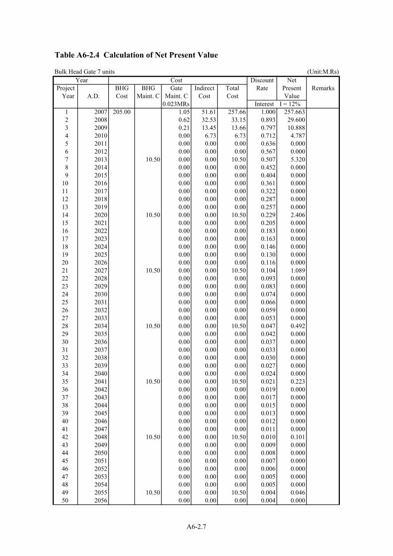
Table A6-2.4 Calculation of Net Present Value
Bulk Head Gate 7 units (Unit:M.Rs) Year Cost Discount Net
BHG BHG Gate Indirect Total Rate Present RemarksA.D. Cost Maint. C Maint. C Cost Cost Value
0.023MRs Interest I = 12%1 2007 205.00 1.05 51.61 257.66 1.000 257.6632 2008 0.62 32.53 33.15 0.893 29.6003 2009 0.21 13.45 13.66 0.797 10.8884 2010 0.00 6.73 6.73 0.712 4.7875 2011 0.00 0.00 0.00 0.636 0.0006 2012 0.00 0.00 0.00 0.567 0.0007 2013 10.50 0.00 0.00 10.50 0.507 5.3208 2014 0.00 0.00 0.00 0.452 0.0009 2015 0.00 0.00 0.00 0.404 0.000
10 2016 0.00 0.00 0.00 0.361 0.00011 2017 0.00 0.00 0.00 0.322 0.00012 2018 0.00 0.00 0.00 0.287 0.00013 2019 0.00 0.00 0.00 0.257 0.00014 2020 10.50 0.00 0.00 10.50 0.229 2.40615 2021 0.00 0.00 0.00 0.205 0.00016 2022 0.00 0.00 0.00 0.183 0.00017 2023 0.00 0.00 0.00 0.163 0.00018 2024 0.00 0.00 0.00 0.146 0.00019 2025 0.00 0.00 0.00 0.130 0.00020 2026 0.00 0.00 0.00 0.116 0.00021 2027 10.50 0.00 0.00 10.50 0.104 1.08922 2028 0.00 0.00 0.00 0.093 0.00023 2029 0.00 0.00 0.00 0.083 0.00024 2030 0.00 0.00 0.00 0.074 0.00025 2031 0.00 0.00 0.00 0.066 0.00026 2032 0.00 0.00 0.00 0.059 0.00027 2033 0.00 0.00 0.00 0.053 0.00028 2034 10.50 0.00 0.00 10.50 0.047 0.49229 2035 0.00 0.00 0.00 0.042 0.00030 2036 0.00 0.00 0.00 0.037 0.00031 2037 0.00 0.00 0.00 0.033 0.00032 2038 0.00 0.00 0.00 0.030 0.00033 2039 0.00 0.00 0.00 0.027 0.00034 2040 0.00 0.00 0.00 0.024 0.00035 2041 10.50 0.00 0.00 10.50 0.021 0.22336 2042 0.00 0.00 0.00 0.019 0.00037 2043 0.00 0.00 0.00 0.017 0.00038 2044 0.00 0.00 0.00 0.015 0.00039 2045 0.00 0.00 0.00 0.013 0.00040 2046 0.00 0.00 0.00 0.012 0.00041 2047 0.00 0.00 0.00 0.011 0.00042 2048 10.50 0.00 0.00 10.50 0.010 0.10143 2049 0.00 0.00 0.00 0.009 0.00044 2050 0.00 0.00 0.00 0.008 0.00045 2051 0.00 0.00 0.00 0.007 0.00046 2052 0.00 0.00 0.00 0.006 0.00047 2053 0.00 0.00 0.00 0.005 0.00048 2054 0.00 0.00 0.00 0.005 0.00049 2055 10.50 0.00 0.00 10.50 0.004 0.04650 2056 0.00 0.00 0.00 0.004 0.000
Project Year
A6-2.7

A6-3.1
A 6-3 Structural Calculation of the Under Sluice Gate
1-1 Design Condition Gate Type : Plate Girder Type Roller Gate Gate Quantity : 7 sets Clear Span : 60.00 ft [18.29 m] Leaf Height : 23.00 ft [7.01 m] Design Water Head : Upstream 23.00 ft [7.01 m] Downstream 0.00 ft [0.00 m] Operating Water Head : Upstream 23.00 ft [7.01 m] Downstream 0.00 ft [0.00 m] Design Sedimentation Height : 6.00 ft [1.83 m] Gate Sill Elevation : RL 425.00 ft [EL129.54 m] Sealing Type : 3 Edges With Rubber Seals at Upstream Hoist Type : 1 Motor 2 Drum Wire Winch Operating Method : Local Control Operating Speed : 1.0 ft/min±10 % [ 0.3 m/min±10 %] Lifting Height : 32.00 ft [ 9.75 m ] Corrosion Allowance : One Side 0.5 mm Allowable Stress : By Technical Standard for Gate and Penstocks Allowable Deflection : Bellow 1/600
1-2 Load 1-2-1 Design Load Hydrostatic Load Sediment Load
mkN240.96)0.00(7.012
9.807
)H(H2
P
22
22
21
1s
=−×=
−⋅=γ
Total Hydrostatic Load Ps=Ps・B=240.96×18.72=4,511 kN
Total Load
P=Ps + Pm =4,511+123=4,634 kN
RL 448.00 ft
RL 425.00 ft
H1
RL 425.00 ft 1.83
m
・B h ・ ・W C ・ 21 =P 2
m1em
kN123
18.721.839.8070.4021 2
=
××××=

A6-3.2
1-2-2 Assignment Load of Main Girder
Total of Unit Load
Hydrostatic Load (kN/m)
Sediment Load (kN/m)
Total (kN/m)
① Ra 50.04 50.04 ② Rb 50.33 50.33 ③ Rc 72.37 1.34 73.71 ④ Rd 68.23 5.23 73.46
1-2-3 Mean Pressure Worked on Skin Plate
Sediment Load Hydrostatic Load

A6-3.3
1-2-4 Reaction Force of Roller
Reaction Force of Roller (kN) Rolller No Hydrostatic Pressure Sediment Pressure Total ① 51 0 51 ② 70 0 70 ③ 89 0 89 ④ 99 0 99 ⑤ 106 0 106 ⑥ 112 0 112 ⑦ 114 0 114 ⑧ 114 0 114 ⑨ 115 0 115 ⑩ 118 0 118 ⑪ 120 0 120 ⑫ 121 0 121 ⑬ 120 1 121 ⑭ 119 3 122 ⑮ 118 5 123 ⑯ 115 6 121 ⑰ 112 7 119 ⑱ 108 8 116 ⑲ 103 9 112 ⑳ 100 9 109 21 131 13 144
① Hydrostatic Load ② Sediment Load

A6-3.4
1-3 The result of Strength Consideration for Main Parts 1-3-1 Gate Leaf
① Bending Stress,Shearing Stress,Deflection and Ratio of Deflection
Main Girder ③ Cross Section H-2,200×300×12/25(SM490)
Corrosion Allowance One Side 0.5 mm Moment of Inertia of Area I =2,730,842×104 mm4 Modulus of Section Z =23,838×103 mm3 Area of Web A =236.6×102 mm2 Bending Stress and Shearing Stress of Main Girder
Unit Load(kN/m) Bending Moment(kN・m) Shearing Force(kN) ③ Rc 73.71 3,404 690
② Stress of Skin Plate
22
tpak
1001 ⋅⋅⋅=σ
σ:Bending Stress (N/mm2)
k:Factor a:Short Side of a Rectangle (mm) b:Long Side of a Rectangle (mm) p:Pressure (N/mm2) t :Plate Thickness (mm)
Stress Bending Shearing
No σ N/mm2
Allowable Stress σa N/mm2
τ N/mm2 Allowable
Stress τa N/mm2
Ratio of Deflection λ
Allowable Ratio of
Deflection λa
③ 143 158 29 91 1/ 825 1/ 600
Short Side of a
Rectangle a
mm
Long Side of a
Rectangle b
mm
B/a Factor
k
Pressure p
N/mm2
Plate Thickness
t mm
Stress σ
N/mm2
Allowable Stress σa N/mm2
③ 850 1,400 1.65 47.4 0.0443 11 125 158
b
σ4
σ3
σ2 σ1
0.3σ4
0.3σ1
a
Stress Distribution of Skin Plate

A6-3.5
③ Bending Stress and Shearing Stress of Vertical Girder 1)Sub Vertical Girder
)ba(324
bpM 22 −= ・・・ )
2b(a
2bpS −= ・・
Cross Section BT-200×75×12/12 (SM400) Corrosion Allowance One Side 0.5 mm
Moment of Inertia of Area I =1,187×104 mm4 Modulus of Section Z =97×103 mm3 Area of Web A =20.7×102 mm2 2)Side Girder Maximum Bending Moment 6.00 kN・m(①) Maximum Shearing Moment 62 kN(⑭) Cross Section H-540×150×9/16 (SM400) Corrosion Allowance One Side 0.5 mm Moment of Inertia of Area I =40,036×104 mm4 Modulus of Section Z =1,472×103 mm3 Area of Web A =40.7×102 mm2
No a b Pu(kN/m2) Pd(kN/m2) p(kN/m2) M(kN・m) S(kN) ④ 1.499 0.570 51.16 71.74 61.45 9.36 21
P→ a
b
b
P 1
kN/m
a A
c C B
P 2
kN/m
P 3
kN/m
( ) xaPP21M 21A ⋅⋅+=
xP2cM 3B ⋅⋅=
3322
31c x
6bPP
2xP
xRM ⋅−
−⋅
⋅= -
b6
PP2R 231 ⋅
+⋅= b
6P2PR 23
2 ⋅⋅+=

A6-3.6
Stress
Bending Shearing σ N/mm2
Allowable Stressσa N/mm2 τ N/mm2
Allowable Stress τa N/mm2
Sub Vertical Girder 96 10
Side Girder 4 118
15 68
1-3-2 Roller
Working Load of Main Roller P = 144 kN Diameter of Roller D = φ150 mm Clear Seating Width of Roller B = 130 mm Diameter of Wheel Pin d = φ 70 mm Material of Roller SCMn3B Rollers Brinel Hardness HB = 200
Strength of a Roller Contact Stress p (for Line Contact)
( )21
21
EERBoEEP
0.591p+⋅⋅
⋅⋅⋅=
Contact Stress p= 717 N/mm2 < Allowable Contact Stress Pa=754 N/mm2 Bearing Pressure of Wheel Pin
bdP
P ⋅=σ
σp= 16 N/mm2 < 23 N/mm2 (Oil less metal)
B= 130
d=φ
70
D=φ
150
P :Hertz Contact Stress (N/mm2) P :Working Load of Roller = 144,000 N E1 :Modulus of Elasticity of Roller = 20.6×10⁴ N/mm2 E2 :Modulus of Elasticity of Rail = 19.3×10⁴ N/mm2
Bo :Clear Seating Width of Roller = 130 mm R :Radius of Roller = 75 mm
P:Working Load of Roller = 144,000 N d:Diameter of Wheel Pin = 70 mm b:Clear Width of Bearing = 130 mm

A6-3.7
1-3-3 Gate Guide Contact Stress σc=910 N/mm2 < σall=1,029 N/mm2 1-4 Hoisting Load
Opening Load 265 kN , Closing Load 40 kN , Downward Load at Raising 660 kN
1-5 Hoist 1-5-1 Design Condition of Hoist Type of Hoist Electrically Driven,1 Motor 2 Drum Type Quantity of Hoist 7 set Hoisting Load Raising 265 kN Hoisting Speed 0.3 m/min ± 10 % Lifting Height 9.75 m Operating Method Local Control Number of Rope Falls 1 at each side,2 at both side Power Source Three-phase Ac 400V 50 Hz Safety Factor By Technical Standard for Gate and Penstocks 1-5-2 Mechanical Efficiency of Machinery
Start Total Efficiency η 0.658
1-5-3 Design Date of Wire Rope
Construction IWRC 6×P・WS(36) Diameter of Rope d = φ 60 mm Breaking Strength Fa = 2,780 kN
Item Opening Closing Downward Load at Raising
Weight of Gate Leaf 520 ↓ 520 ↓ 520 ↓ Frictional Force of Wheel Rotation 62 ↓ 62 ↑ 62 ↓
Frictional Force of the Rubber Seal 27 ↓ 27 ↑ 27 ↓
Frictional Force between Sediment and Metal
49 ↓ 0 ↑ 49 ↓
Counter Weight 395 ↑ 395 ↑ 0 ↑ Total 263 ↓ 36 ↓ 658 ↓
Cb
t t
P1
2
D1
2
D2

A6-3.8
1-5-4 Diameter of Drum 19dDd ≥ Diameter of Drum mm1401Dd , φ= 1-5-5 Required Capacity
η⋅
⋅=60
VWPM
PM :Required Capacity kw W :Hoisting Load = 265 kN V :Hoisting Speed = 0.3 m/min η :Efficiency of Machinery at start = 0.658
kW 0220.65860
0.3265PM .=×
×=
Therefore we employ the rating of 2.2 kW as the nearest capacity of more 1.5 kW.
Design Date of Motor Type TEFC Capacity 2.2 kW Number of Poles 6 P 50 Hz Rated Number of Rotation 940 r.p.m

A6-4.1
A 6-4 Structural Calculation of the Weir Gate 1-1 Design Condition
Gate Type : Trussed Type Roller Gate Gate Quantity : 22 set Clear Span : 60.00 ft [18.29 m] Leaf Height : 20.00 ft [6.10 m] Design Water Head : Upstream 20.00 ft [6.10 m] Downstream 0.00 ft [0.00 m] Operating Water Head : Upstream 20.00 ft [6.10 m] Downstream 0.00 ft [0.00 m] Design Sedimentation Height : 3.00 ft [0.91 m] Gate Sill Elevation : RL 428.00 ft [EL130.45 m] Sealing Type : 3 Edges With Rubber Seals at Upstream Hoist Type : 1 Motor 2 Drum Wire Winch Operating Method : Local Control Operating Speed : 1.0 ft/min±10 % [ 0.3 m/min±10 %] Lifting Height : 29.00 ft [ 8.84 m ] Corrosion Allowance : One Side 0.5 mm Allowable Stress : By Technical Standard for Gate and Penstocks Allowable Deflection : Bellow 1/600
1-2 Load 1-2-1 Design Load Hydrostatic Load Sediment Load
mkN182.46)0.00(6.102
9.807
)H(H2
P
22
22
21
1s
=−×=
−⋅=γ
Total Hydrostatic Load kN3,41018.69182.46BsPsP =×=⋅=
Total Load P = Ps + Pm =3,410 + 30=3,440 kN
RL 428.00 ft
RL 448.00 ft
H1
RL 428.00 ft 0.91
m
kN30
18.690.9180790.4021 2
.
=
××××=
BhWC21P 2
m1em ⋅⋅⋅⋅=

A6-4.2
1-2-2 Hydrostatic Load of Bottom Raising
1-2-3 Reaction Force of Roller
① Hydrostatic Load ② Sediment Load (kN)
Roller No Hydrostatic Presssure Sediment Pressure Total
① 156 0 156 ② 147 0 147 ③ 135 0 135 ④ 131 0 131 ⑤ 129 0 129 ⑥ 128 0 128 ⑦ 128 0 128 ⑧ 126 0 126 ⑨ 125 0 125 ⑩ 126 1 127 ⑪ 125 3 128 ⑫ 120 5 125 ⑬ 131 7 138
241
216
10
11
12 13
4
5
6
7
8
9
902
1377
57
8
13.50 kN/m2 1
2
464
3
400
356
330
305
279
267
254
22.35 kN/m2
28.02 kN/m2
32.57 kN/m2
36.49 kN/m2
39.98 kN/m2
43.22 kN/m2
46.21 kN/m2 48.95 kN/m2 51.57 kN/m2 54.06 kN/m2 56.42 kN/m2 58.54 kN/m2 59.82 kN/m2
131
Des
ign
Wat
er H
ead

A6-4.3
1-3 The result of Strength Consideration for Main Parts 1-3-1 Gate Leaf ① Existing Main Girder Cross Section
Downstream Girder 2-L-203×152×19(ASTM A36) Upstream Girder 2-L-152×152×16 PL9.5×425(ASTM A36)
Stress (N/mm2)
Main Girder Downstream Upstream Allowable Stress
Lowest Girder 102 123 124
Ratio of Deflection
Main Girder Deflection
(mm)
Ratio of
Deflection
Allowable
Deflection
Lowest Girder 28.0 1/668 1/600 ② Bottom Raising 1)Skin Plate Bending Moment Modulus of Section (per unit width)
Bending Stress σb= ZM= 108 N/mm2 < σa=118 N/mm2 (SM400)
2)Bending Stress of Girder ⑥ Working Load of Girder ⑥
kN/m25.67Lb6
)q2(qR 2
6
756 =
+= ・
・・
Bending Moment
m・・ kN 4.388BRM
2==
Cross Section [-200×80×7.5/11 (SS400) Corrosion Allowance One Side 0.5 mm Moment of Inertia of Area I =1,774×104 mm4 Modulus of Section Z=175×103 mm3
/m 1.3056.25)2(5.7716
0.42
)2q(q16HM
2
21
2
mkN・ =×+=
+=
322
mm1268.51.0
6tbZ =×=⋅=
56.25 kN/m2
q2=56.25 kN/m2
62.02 kN/m2
q1=5.77 kN/m2
H=4
20
(200)199.5
(11) (11) 10 10.5
(80)
(7.5
) 79
6.5

A6-4.4
Bending Stress σb= ZM= 25 N/mm2 < σa=118 N/mm2
3)Slanting Material
kN152
BRR 6 ==
・
kN16cos
RR N ==θ
kN5sinRR V == θ・
Cross Section L-75×75×9 (SS400) Corrosion Allowance One Side 0.5 mm
Moment of Inertia of Area I=58×104 mm4 Modulus of Section Z=11×103 mm3
Compression Stress σt= ZM=14 N/mm2 < σa= 71N/mm2
③ Side Girder Maximum Bending Moment 39.88 kN・m(①)
Maximum Shearing Moment 82 kN(①)
Cross Section H-400×150×12/22 (SM400) Corrosion Allowance One Side 0.5 mm
b
P 1
kN/m
a A
c C B
P 2
kN/m
P 3
kN/m
( ) xaPP21M 21A ・・+=
xP2cM 3B ・・=
3322
31c x
6bPP
2xP
xRM ・・
-・−
−=
b6
PP2R 23
1 ・・ +
= b6
P2PR 23
2 ・・+
=
R6=25.67 kN/m
B=1.168
L-75×75×9
R=15 kN 1929
L-75×75×9
θ=19.4°
640
8 (9)
66
74 (75)
8 (9)
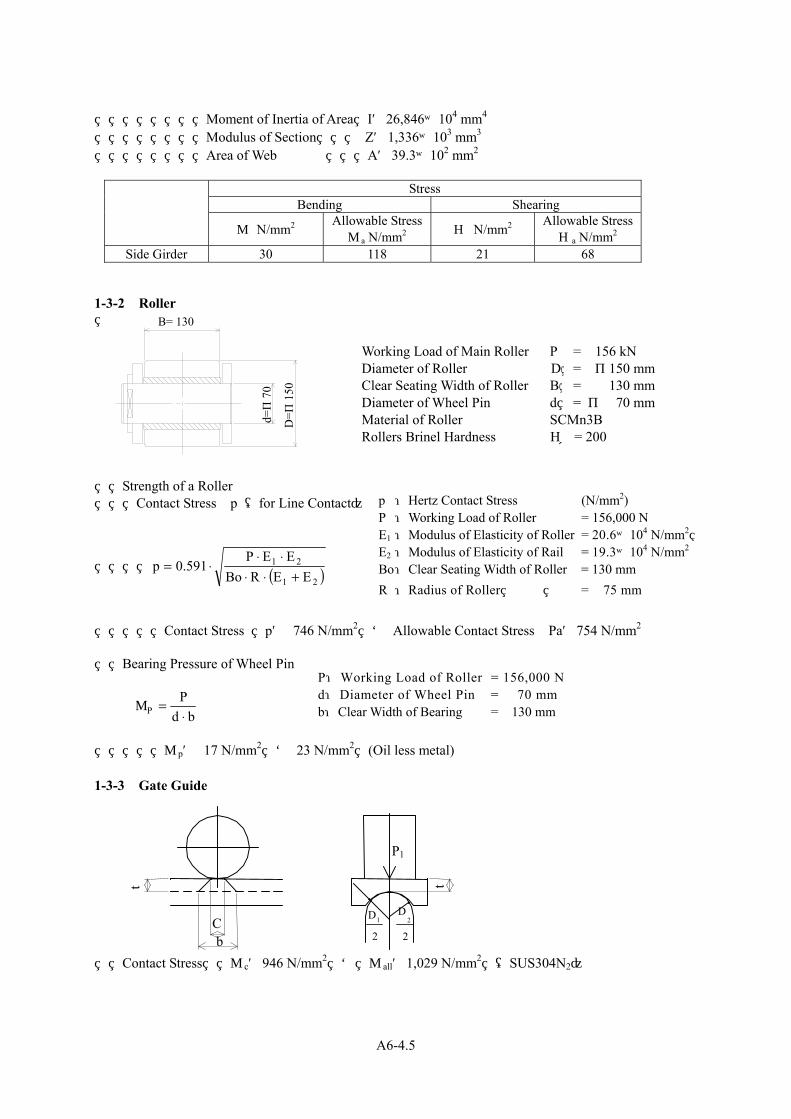
A6-4.5
Moment of Inertia of Area I=26,846×104 mm4 Modulus of Section Z=1,336×103 mm3 Area of Web A=39.3×102 mm2
Stress
Bending Shearing σ N/mm2
Allowable Stressσa N/mm2 τ N/mm2
Allowable Stress τa N/mm2
Side Girder 30 118 21 68 1-3-2 Roller
Working Load of Main Roller P = 156 kN Diameter of Roller D = φ150 mm Clear Seating Width of Roller B = 130 mm Diameter of Wheel Pin d = φ 70 mm Material of Roller SCMn3B Rollers Brinel Hardness HB= 200
Strength of a Roller Contact Stress p (for Line Contact)
( )21
21
EERBoEEP
0.591p+⋅⋅
⋅⋅⋅=
Contact Stress p= 746 N/mm2 < Allowable Contact Stress Pa=754 N/mm2 Bearing Pressure of Wheel Pin
bdP
P ⋅=σ
σp= 17 N/mm2 < 23 N/mm2 (Oil less metal) 1-3-3 Gate Guide Contact Stress σc=946 N/mm2 < σall=1,029 N/mm2 (SUS304N2)
B= 130
d=φ
70
D=φ
150
C b
t t
P1
2
D1
2
D2
p :Hertz Contact Stress (N/mm2) P :Working Load of Roller = 156,000 N E1 :Modulus of Elasticity of Roller = 20.6×10⁴ N/mm2 E2 :Modulus of Elasticity of Rail = 19.3×10⁴ N/mm2
Bo :Clear Seating Width of Roller = 130 mm R :Radius of Roller = 75 mm
P:Working Load of Roller = 156,000 N d:Diameter of Wheel Pin = 70 mm b:Clear Width of Bearing = 130 mm

A6-4.6
1-4 Hoisting Load
Opening Load 165 kN , Closing Load 20 kN , Downward Load at Raising 510 kN 1-5 Hoist 1-5-1 Design Condition of Hoist Type of Hoist Electrically Driven,1 Motor 2 Drum Type Quantity of Hoist 22 set Hoisting Load Raising 165 kN Hoisting Speed 0.3 m/min ± 10 % Lifting Height 8.84 m Operating Method Local Control Number of Rope Falls 1 at each side,2 at both side Power Source Ac 400V 50 Hz Safety Factor By Technical Standard for Gate and Penstocks 1-5-2 Mechanical Efficiency of Machinery
Start Total Efficiency η 0.658
1-5-3 Design Date of Wire Rope
Construction IWRC 6×WS(36)特種 Diameter of Rope d = φ 56 mm Breaking Strength Fa = 2,230 kN
1-5-4 Diameter of Drum 19dDd ≥ Diameter of Drum mm1201Dd , φ= 1-5-5 Required Capacity
η⋅
⋅=60
VWPM
PM :Required Capacity kW W :Hoisting Load = 165 kN V :Hoisting Speed = 0.3 m/min η :Efficiency of Machinery at start = 0.658
Item Opening Closing Downward Load at Raising
Weight of Gate Leaf 430 ↓ 430 ↓ 430 ↓ Frictional Force of Wheel Rotation 46 ↓ 46 ↑ 46 ↓
Frictional Force of the Rubber Seal 21 ↓ 21 ↑ 21 ↓
Frictional Force between Sediment and Metal
12 ↓ 0 ↑ 12 ↓
Counter Weight 345 ↑ 345 ↑ 0 ↑ Total 164 ↓ 18 ↓ 509 ↓

A6-4.7
kW 1.250.65860
0.3651PM =×
×=
Therefore we employ the rating of 1.5 kW as the nearest capacity of more 0.75 kW.
Design Date of Motor Type TEFC Capacity 1.5 kW Number of Poles 6 P 50 Hz Rated Number of Rotation 880 r.p.m

A6-4.8
【Reference】Three Dimensions Analysis for Existing Structure of Weir Gate
1.Design Condition
Gate Type : Trussed Type Roller Gate
Gate Quantity : 22 set
Clear Span : 60.00 ft [18.29 m]
Leaf Height : 20.00 ft [6.10 m]
Design Water Head : Upstream 20.00 ft [6.10 m]
Downstream 0.00 ft [0.00 m]
Operating Water Head : Upstream 20.00 ft [6.10 m]
Downstream 0.00 ft [0.00 m]
Design Sedimentation Height : 3.00 ft [0.91 m]
Gate Sill Elevation : RL 428.00 ft [EL130.45 m]
Sealing Type : 3 Edges With Rubber Seals at Upstream
Hoist Type : 1 Motor 2 Drum Wire Winch
Operating Method : Local Control
Operating Speed : 1.0 ft/min±10 % [ 0.3 m/min±10 %]
Lifting Height : 29.00 ft [ 8.84 m ]
Corrosion Allowance : One Side 0.5 mm
Allowable Stress : By Technical Standard for Gate and Penstocks
Allowable Deflection : Bellow 1/600
2. Main Girder Cross Section Downstream Girder 2-L203×152×19(ASTM A36) Upstream Girder 2-L152×152×16 PL9.5×425(ASTM A36)
3. Unit Load
Highest Girder 5 : 24.379 kN/m
Main Girder 4 : 25.871 kN/m
Main Girder 3 : 32.351 kN/m
Main Girder 2 : 17.920 kN/m
Lowest Girder 1 : 83.325 kN/m

A6-4.9
4. Results of Calculation
Stresses (N/mm2)
Main Girder Main Girder of
Downstream Side
Main Girder of
Upstream Side
5(most upper
section) 92 -85
4 85 -93
3 91 -94
2 89 -124
1(most lower
section) 102 -123
Deflection (mm)
Main Girder Deflection Deflection
Intensity
5(most upper
section) 24.4 1/766
4 24.7 1/757
3 25.4 1/736
2 26.1 1/716
1(most lower
section) 28.0 1/668
Show the Drawings of Deflection and Stress Range to next Appendix.

App
endi
x
Stre
sses
of M
ain
Gird
er
XY
Z
101.
9
89.6
7
77.4
4
65.2
2
53.
40.7
8
28.5
6
16.3
4
4.11
9
-8.1
02
-20.
32
-32.
54
-44.
76
-56.
99
-69.
21
-81.
43
-93.
65
V1
L3 C1
Out
put S
et: M
SC
/NA
STR
AN
Cas
e 1
Con
tour
: Bar
End
A A
xial
Stre
ss
Figu
re-1
Dra
win
gs o
f Str
esse
s of M
ain
Gir
der
for
Dow
nstr
eam
Sid
e (N
/mm
2 )
σ=1
02 N
/mm
2
σ=9
2 N
/mm
2
σ=8
5 N
/mm
2
σ=9
1 N
/mm
2
σ=8
9 N
/mm
2
A6-4.10

XY
Z
101.
9
87.7
9
73.6
9
59.5
8
45.4
8
31.3
7
17.2
6
3.15
6
-10.
95
-25.
06
-39.
16
-53.
27
-67.
37
-81.
48
-95.
59
-109
.7
-123
.8
V1
L3 C1
Out
put S
et: M
SC
/NA
STR
AN
Cas
e 1
Con
tour
: Bar
End
A M
in C
omb
Stre
ss
Figu
re-2
Dra
win
gs o
f Str
esse
s of M
ain
Gir
der
for
Ups
trea
m S
ide
(N/m
m2 )
σ=-
123N
/mm
2
σ=-
85N
/mm
2
σ=-
93N
/mm
2
σ=-
94N
/mm
2
σ=-
124N
/mm
2
A6-4.11

Def
lect
ion
XY
Z
V1
L3 C1
Out
put S
et: M
SC
/NA
STR
AN
Cas
e 1
Def
orm
ed(2
8.34
): To
tal T
rans
latio
n
Fi
gure
-3
Dra
win
gs o
f Def
lect
ion
Y=2
8.0
Y=2
4.4
A6-4.12

A6-5.1
A 6-5 Structural Calculation of the Bulk Head Gate
1-1 Design Condition Gate Type Steel Floating Gate
Gate Quantity 5 set
Clear Span 60.00 ft [18.29 m ]
Gate Height 25.26 ft [ 7.70 m ]
Design Water Head 25.26 ft [7.70 m ]
Gate Sill Elevation RL 423.00 ft [EL128.93 m]
Sealing Type 3 Edges With Rubber Seals at Downstream
Corrosion Allowance One Side 0 mm (side where it touches water)
Allowable Deflection Below 1/600
1-2 Load 1-2-1 Design Load
21
1s H
2p ×=γ
ps :Hydraulic Load (kN/m) Hs :Sealing Height = 7.70 m H1 :Design Head at Upstream = 7.70 m Bs :Sealing Span = 20.32 m γ1 :Weight of Water Per Unit Volume = 9.807 kN/m3
kN/m 290.737.702
9.807p 2s =×=
Total Load
kN908520.32290.73BpP sss ,=×=⋅=
H1
RL 423.00
RL 448.26

A6-5.2
1-2-2 Assignment Load
Water Head of Upper Block Bottom h1 = 2.500 m Pressure of bottom q1 = 24.52 kN/m2 Water Head of Middle Block Bottom h2 = 4.700 m q2 = 46.09 kN/m2 Water Head of Lower Block Bottom h3 = 7.700 m q3 = 75.51 kN/m2
Height of Upper Block b1 = 2.500 m Height of Middle Block b2 = 2.200 m Height of Lower Block b3 = 3.000 m
Load of Upper Block
kN/m 30.652.5002
24.52b2
qW 1
1g =×=⋅=
Load of Middle Block
kN/m77.672.2002
46.0924.52b2
qqW 2
21g =×+=⋅
+=
Load of Lower Block
kN/m182.403.0002
75.5146.09b2
qqW 3
32g =×+=⋅
+=
q3=75.51 kN/m
q2=46.09 kN/m
q1=24.52 kN/m
7700 2200
3000
2500
500
2500
7700
4700
2500

A6-5.3
1-3 The result of Strength Consideration for Main Parts(Lower Block) 1-3-1 Gate Leaf ① Stress Load
Arrangement and Hydraulic Pressure of Side Girder
q2 = 46.09 N/mm2 q3 = 75.51 N/mm2
L = 3.000 m
Center of Bottom (from Bottom)
m1.37975.5146.09
3.000/375.51)46.09(2)q(qL/3)q(2q
ho32
32 =+
×+×=+
⋅+=
Total Load W = 182.40 kN/m
Assignment Load
kN/m 46.095001
379182.40L
aWW1 ,
=×=⋅=
kN/m136.315001
1,121182.40L
bWW2 ,
=×=⋅=
Cross Section Property Central Part Moment of Inertia of Area I =15,558,765×104 mm4 Modulus of Section Z =103,905×103 mm3 Area of Web A=596×102 mm2 Side Part Moment of Inertia of Area I =3,612,043×104 mm4 Modulus of Section Z =36,120×103 mm3 Area of Web (Side Part) A =181×102 mm2
3000
2500
50
0
3000
500
500
1500
q3
q2
3000
1000
500
1621
1379
1121
379
W
W1
W2

A6-5.4
② Bending Stress and Shearing Stress of Stiffeners
1)Horizontal Stiffener
Working Load
P3=6.700×9.807×0.500=32.85 kN/m h :Design Water Head = 6.700 m wo :Weight of Water Per Unit Volume = 9.807 kN/m3 L1 :Horizontal Stiffeners’ Pitch = 0.500 m Bending Moment(M) and Shearing Moment(Q)
mN9.871.5532.8581LP
81M 22
23 ・k =××=⋅⋅=
kN251.5532.8521LP
21Q 23 =××=⋅⋅=
L2:Vertical Stiffener’s Pitch = 1.550 m Moment of Inertia of Area I =2,192×104 mm4 Modulus of Section Z =563×103 mm3 Area of Web A=12.7×102 mm2 2)Vertical Stiffener Working Load
W3=5.950×9.807×1.550=90.45 kN/m
Vertical Stiffener’s Pitch L = 1.55 m Bending Moment(M) and Shearing Moment (Q)
mkN66702.500459081LW
81M 22
3 ・ .. =××=⋅⋅=
kN1132.500459021LW
21Q 3 . =××=⋅⋅=
L:Height of Lower Block = 2.500 m
Stress Bending Shearing
σ N/mm2
Allowable Stress σa N/mm2
τ N/mm2 Allowable
Stress τa N/mm2
Ratio of Deflection λ
Allowable Ratio of
Defrection λa
Central Part 92 26
Side Part 54
177 67
102 1/ 1,535 1/ 600

A6-5.5
Moment of Inertia of Area I =23,565×104 mm4 Modulus of Section Z =913×103 mm3 Area of Web A =35.0×102 mm2
③ Skin Plate 1)Minimum of Plate Thickness
nf56bt・・
=
Where, b :Width of Stiffener N :The Number of Panels F :The Factor by the Stress slope
Central Part Side Part
t=5156
2,500 =8.9 mm <10 mm t=
51.156563,000
=9.3 mm <10 mm
∴Minimum of Plate Thickness 10 mm
2)Stress Bending Stress of Skin Plate
22
tpak
1001
・・・σ=
Stress Bending Shearing
σ N/mm2 Allowable Stressσa N/mm2 τ N/mm2
Allowable Stressτa N/mm2
Horizontal Stiffener 55 20
Vertical Stiffener 77
177 32
102
150
350
Where、 σ:Skin Plate Stress (N/mm2) k:Factor in Below Table b/a a:Short Side of a Rectangle (mm) b:Long Side of a Rectangle (mm) p:Hydraulic Pressure (N/mm2) t:Plate Thickness (mm) b
σ4 σ3
σ1
σ2 a
× × × ×
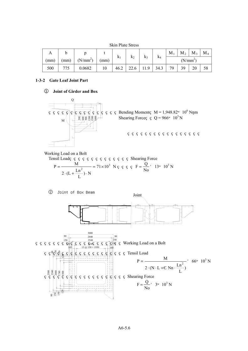
A6-5.6
Skin Plate Stress
σ1 σ2 σ3 σ4A
(mm)
b
(mm)
p
(N/mm2)
t
(mm)k1 k2 k3 k4
(N/mm2)
500 775 0.0682 10 46.2 22.6 11.9 34.3 79 39 20 58 1-3-2 Gate Leaf Joint Part ① Joint of Girder and Box
Bending Moment M = 1,948.82×106 N・m Shearing Force Q = 966×103 N
Working Load on a Bolt Tensil Load Shearing Force
N 1071N)
LLn(L2
MP 32
×=⋅+⋅
= NoQF = =13×103 N
② Joint of Box Beam Working Load on a Bolt Tensil Load
)L
LnNnL(N2
MP2
⋅+⋅⋅=
Σ=66×103 N
Shearing Force
NoQF = =3×10³ N
1800
15
00
1200
90
0 60
0 30
0
M
Q
3000 2840 2540 2240
13 @ 150 = 1950 145
150 150
80
145 150
150
80
2500
23
40
2040
17
40
1500
12
0 15
0 15
0 80
80
15
0 15
0 12
0
Joint

A6-5.7
1-3-3 Gate Guide
Working Load on a Gate Guide Reactions
Upper Beam 209 kN Middle Beam 434 kN Lower Beam 1,210 kN
Bending Moment at Point A
mkN 254.10.2101,210LPM A ・・ =×== Moment of Inertia of Area I =72,298×104 mm4 Modulus of Section Z =4,741×103 mm3 Area of Web A =135.0×102 mm2
Stress Bending Shearing Combined
σN/mm2
Allowable Stress
σa N/mm2 τN/mm2
Allowable Stress
τa N/mm2 σgN/mm2
Allowable Stress
σga N/mm2
Girder and Box 210 38 220
Box and Box 195
259 9
150 196
285
Stress Bending Shearing
σ N/mm2 Allowable Stressσa N/mm2 τ N/mm2
Allowable Stress τa N/mm2
55 177 92 102
P
・A
Effective Width 550
1350
600
300
300
75
75
300
236
32
32
250
210 40

A6-6.1
A 6-6 Structural Reinforcement calculation of Existing Deck Frame 1-1 Design Condition
Live Load :3.5 kN/m2 on all area of deck
Wind Load :1.5 kN/m2
Allowable Stress :By Technical Standard for Gate and Penstocks
Allowable Deflection : Bellow 1/1,000
Considerable Condition
Shed, Gate
tower and
other self
weights
Live
Load
Gate
Operation
Load
Wind load Remarks
During Gate
Operation ○ ○ ○
Under Wind
Load ○ ○ ○ ○ Allowable stress is 1.5 times larger.
Under
Maximum
Torque
○ ○ ○ ○ Allowable stress under maximum
torque is 90% of the yield point.

A6-6.2
1-2 Reinforcement Plan of Under Sluice Gate
1-2-1 Stress Beam-Vertical Beam
Material:2-L76×50×10(SS400)
Maximum Load Case : Case of Hoist Operation
(Dead Load+Live Load+Rating Hoisting Load)
Fix.
Mov.
σc = -68 N/mm2 < σca = 86 N/mm2
軸圧縮力最大箇所 応力度
OK
σc = -85 N/mm2 > σca = 74 N/mm2
補強前 軸圧縮力最大箇所 応力度
OUT
補強前
補強後
2 - PL 50 x 6 (SM400)
補強材断面
補強材
梁 鉛直材
1-2-2 Deflection
Vertical Displacement
δ<δa (mm)
Live Load +
Rated Torque Load 1/1,148< 1/1,000
Maximum stress of Axis Compression OUTN/mm74N/mm76 2
ca2
c =>= σσ
Maximum Stress of Axis Compression OKN/mm86N/mm60 2
ca2
c =<= σσ
FLOW
Vertical beam
Before Reinforcing
After Reinforcing
Reinforcement Material
Section of Reinforcement Material 2-PL50x6 (SM400)

A6-6.3
1-3 Reinforcement Plan of Weir Gate
1-3-1 Stress Pillar-Bracing Beam (Side)
Material:2-L76×50×10(SS400)
Maximum Load Case : Case of Maximum Torque (↑)
(Dead Load+Live Load+Wind Load(Water Flow Direction↑)
+Maximum hoisting Load)
σc = -41 N/mm2 < σca = 61 N/mm2
軸圧縮力最大箇所 応力度
OK
σc = -52 N/mm2 > σca = 46 N/mm2
補強前 軸圧縮力最大箇所 応力度
OUT
補強前
補強後
2 - PL 50 x 6 (SM400)
補強材断面
補強材
Maximum Stress of Axis Compression OKN/mm61N/mm37 2
ca2
c =<= σσ
Maximum stress of Axis Compression OUTN/mm46N/mm47 2
ca2
c =>= σσ
FLOW
斜材 Bracing Beam
Before Reinforcin
After Reinforcing
Reinforcement Material
Section of Reinforcement Material 2-PL50x6 (SM400)

A6-6.4
1-3-2 Stress Beam-Upper Horizontal Beam
Material:2-L76×50×10(SS400)
Maximum Load Case : Case of Hoist Operation
(Dead Load+Live Load+Rating Hoisting Load)
σc = -79 N/mm2 < σca = 84 N/mm2
軸圧縮力最大箇所 応力度
OK
σc = -94 N/mm2 > σca = 75 N/mm2
補強前 軸圧縮力最大箇所 応力度
OUT
補強前
補強後
1 - PL 50 x 9 (SM400)
補強材断面
補強材
梁外側 梁中側 (形状保持リブ 1mピッチ)
1-3-3 Deflection
Vertical Displacement
δ<δa (mm)
Live Load +
Rated Torque Load 1/1,292 < 1/1,000
Maximum Stress of Axis Compression OKN/mm84N/mm79 2
ca2
c =<= σσ
Maximum stress of Axis Compression OUTN/mm75N/mm94 2
ca2
c =>= σσ
上水平材 Upper Horizontal Beams
Before Reinforcing
After Reinforcing
Outside InsideRib(Pitch 1m)
Section of Reinforcement Material 2-PL50x9 (SM400)
Reinforcement Material

A6-7. 1
A 6-7 Incline Design Calculation in Bulk Head Gate Stockyard 1-1 Design Condition
Type Incline with Rails Quantity 1 unit Top End Elevation RL 454.00 ft [EL 138.38 m] Bottom End Elevation RL 430.00 ft [EL 131.07 m] Gradient 5.7° (1:10) Traveling System 1Motor 2Drum Wire Winch Traveling Speed 3.3 ft/min ± 10% [1.0 m/min ± 10%] Operating Method Local control Number of Rope Falls 2 at each side, 4 in total Power Source 3Phase AC400 V, 50 Hz Safety Factor By Technical Standard for Gate and Penstocks
1-2 Schematic Diagram
Fig. A6-7-1.1 Bulk Head Gate Stockyard Incline Schematic Diagram
A A
33.00' [10,060] 33.00'
[10,060]267.40'
[81,500]
525.00'
[160,020]
33.00' [10,060] 158.60'
[48,340]
230.00'
[70,100]197.00'
[60,050]
48.00' [14,630]
[10,060]
[10,060]
[10,060]
33.00' 33
.00'
[89,920]
295.00'
[26,820]
88.00'
33.00'
[12,800]
42.00' [1
0,060] [10,
060]
33.00' 3
3.00'
50T TRUCK CRANE
WINCH STAGE
CART
PLAN

A6-7. 2
1-3 Load 1-3-1 Deadweight and Live Load (Vertical Load)
Bulk Head Gate Deadweight 1,304 kN Cart Deadweight 334 kN Total W = 1,638 kN
1-3-2 Deadweight and Live Load Component Force in the Direction of the Inclination
F1 = W•sinθ
where, W: Deadweight and Live Load, W = 1,638 kN θ : Angle of Incline, θ = 5.7 °
F1 = 1,638 × sin 5.7° = 163 kN 1-3-3 Deadweight and Live Load Component Force in the
Direction Perpendicular to the Inclination PW = W•cosθ
where, W: Dead and Live Load, W = 1,638 kN θ: Angle of Incline, θ = 5.7°
PW = 1,638 × cos 5.7° = 1,630 kN 1-3-4 Rolling Friction Resistance of the Wheels
( )w
212 ・P
R
・rF μμ +=
where, μ1: Coefficient of Rotational Movement of the Wheel, μ1 = 0.1 μ2 : Coefficient of Rolling Friction of the Wheel axle, μ2 = 0.01
r : Radius of the Wheel axle, r = 6.0 cm R : Radius of the Wheel, R = 30.0 cm PW: Deadweight and Live Load Component Force in the Direction Perpendicular to the
Inclination, PW = 1,630 kN
( ) kN91,63030
6.00.010.1F2 =××+=
1-3-5 Wind Load
FW = q•A•C where, q:Wind Load Per Unit Projected Area at the Design Wind Velocity During the Use of the Incline (converted using the velocity ratio since the value is proportional to the square of the velocity; kN/m2)

A6-7. 3
2
00 v
vqq
⋅=
where, q0 : Wind Load per Unit Projected Area at the Design Wind Velocity (40 m/s), q0 = 2.94 kN/m2 v0 : Design Wind Velocity, v0 = 40 m/s v : Design Wind Velocity during the Use of the Incline, v = 15 m/s
22
kN/m0.4140152.94q =
×=
A:Vertical Projected Area of the Bulk Head Gate and Cart (m2) A = B1・H1 + B2・H2
Where, B1 : Gate Leaf Width of Bulk Head Gate,B1 = 20.7 m H1 : Gate Leaf Depth of Bulk Head Gate,H1 = 3.0 m B2 : Width of Cart,B2 = 13.8 m H2 : Height of Cart,H2 = 2.0 m
A = 20.7 × 3.0 + 13.8 × 2.0 = 89.7 m2 C:Shape Factor, C = 1.2 (for the Planar Shape) FW = 0.41 × 89.7 × 1.2 = 44 kN 1-3-6 Hoisting Load
Unit:kN Item Hoisting
Deadweight and Live Load Component Force in the Direction of the Inclination
F1 163 ↓
Rolling Friction Resistance of the Wheels F2 9 ↓
Wind Load FW 44 ↓
Total F 216 ↓ Hoisting Load:216 kN
1-4 Operating Device Motor Capacity
η⋅⋅=
60VFPM
where, PM : Required Capacity (kW) F : Hosting Load = 216 kN V : Hoisting Speed = 1.0 m/min η : Efficiency of Machinery at Start = 0.668
5.4 = 0.66860
1.0216 =PM ×× kW
We employ the rating of 5.5 kW as the nearest capacity of more 3.7 kW. Design Data of Motor
Type TEFC, outdoor type (brake) Capacity 5.5 kW (continuous cruising power) Number of Poles 6 P, 50 Hz Rated Number of Rotation 950 r.p.m.

A6-8.1
A 6-8 Capacity Calculation of Emergency Generator for Gate Operation
1-1 Generator capacity calculation
Operating condition should be possible to operate ten(10) sets of under sluice gates motor as maximum. (If should be possible to start two(2) sets of under sluice gates motor at the same time, when the eight(8) sets of under sluice gates motor is operating.) Also power source of local control panel is turned on during gate operating, and maximum are ten(10) sets. Determine the generator capacity from the loads of this equipment (see Table A 6-8-1.1 Table of loads).
Table A6-8-1.1 Table of loads
Output
power
Factors Input
capacity
Total
No. Description of load
(kW)
Quantity of
the device
Quantity of
the device to
be operated Efficiency Power (kVA) (kVA)
Remarks
1 Weir gate motor 1.5 50 0 0.85 0.8 2.2 0.0 Three-
phase
2 Under sluice gate
motor 2.2 14 10 0.85 0.8 3.2 34.2
Three-
phase
3 Local control panel
control supply 0.5 64 10 1 1 0.5 5.0
Single-
phase
4 Low voltage switch
board control supply 2 1 1 1 1 2.0 2.0
Single-
phase
1-1-1 Steady-state load capacity
PG1 = [ Po / (ηx Pf ) +Pi ] xα(kVA) where, PG1 : Steady-state load capacity (kVA)
Po : Output of each load (kW) Maximum number are ten (10) sets of under sluice gate motor.
2.2 kVA x 10 unit = 22 kVA η : Efficiency of each load = 0.85 Pf : Power factor of each load = 0.80 Pi : Load capacity (kVA) other than Po Local control panel load capacity: 0.5 kVA x 10 panels = 5.0 kVA Switchboard load capacity: 2.0 kVA x 1 board = 2.0 kVA Total load capacity: 5.0 kVA + 2.0 kVA = 7.0 kVA α : Demand factor = 1.0
PG1 = [( 22.0 / (0.85 x 0.80 ) ) + 7.0] x 1.0 = 39.4 (kVA)

A6-8.2
1-1-2 Capacity for transient maximum voltage drop
PG2 = Ps x [ (1 / Vd ) - 1 ] x Xd' (kVA) where, PG2 : Capacity for transient maximum voltage drop (kVA) Ps : Starting capacity of the motor with the largest starting capacity (kVA) Ps = Pm xβx C= 4.4 x 7.2 x 1.0 = 31.7 (kVA)
Pm : Output of the motor with the largest value after multiplying the output (kW) by factorsβand C
Maximum capacity is under sluice gates motor which start at the same time 2.2 kVA x 2 unit = 4.4 kVA
β : Motor starting capacity per 1 kW = 7.2 (kVA) . C : Starting factor by starting system (see Table A 6-8-1.2) Use 1.0 for full-voltage
starting. Xd' : Average of the generator’s transient reactance and initial transient reactance = 0.25 Vd : Allowable momentary voltage drop rate =use 0.2 for normal condition.
Table A 6-8-1.2 Starting factor for the squirrel-cage induction motor
Notes: X : Tap used (%) PG2 = 31.7 x [ ( 1 / 0.2 ) - 1 ] x 0.25 = 31.7 (kVA)
1-1-3 Capacity for transient peak output
where, PG3 : Capacity for transient peak output (kVA) PB : Base load active power (kW)
PB = Pn - Pm = 29.0 – 4.4 = 24.6 (kW) QB : Base load reactive power (kvar)
QB = Qn - Qm = 16.3 – 3.2 = 13.1 (kVA) Pms : Starting active power of the load with the largest starting capacity (kW) Pms = Ps x Pfs = 31.7 x 0.4 = 12.7 (kW) Qms : Starting reactive power of the load with the largest starting capacity (kvar)
Qms = KG3 : Generator short-time capacity (Use 1.5 for normal condition.)
C
RectorK ondorfer
X / 100
1.0Full-voltage startngY - ∆ ( at switch operation) 2/3
Starting system
(X / 100)2
(kVA)/KG3)Q(QB)P(PBPG3 2ms
2ms +++=
)kVA(0.29=)4.0(-1x7.31=)P(-1xP 22mss
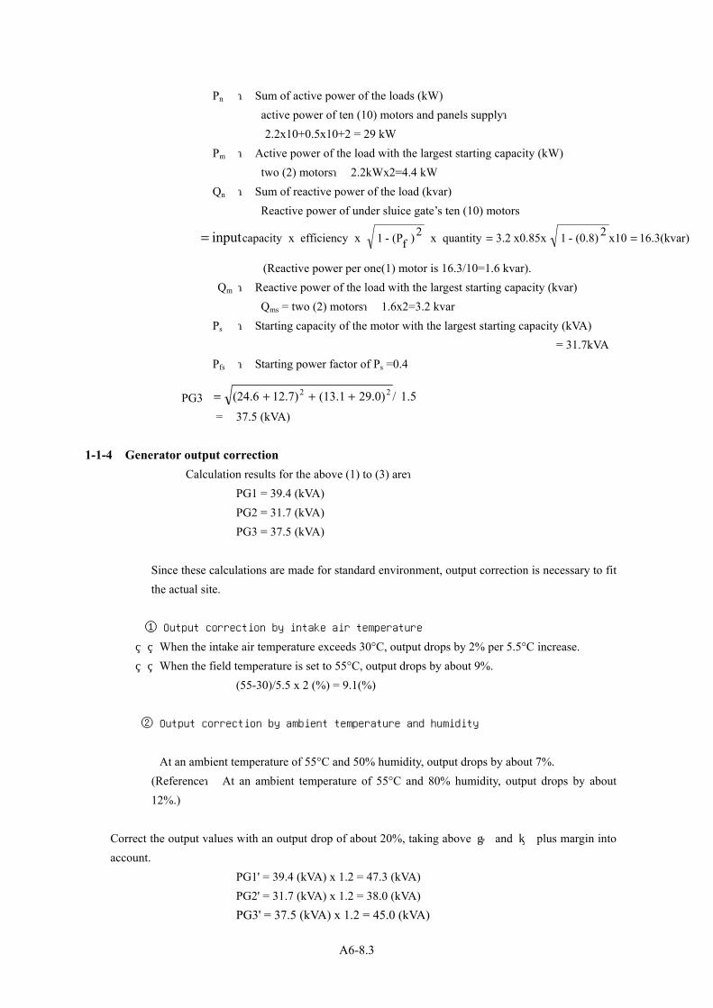
A6-8.3
Pn : Sum of active power of the loads (kW) active power of ten (10) motors and panels supply:
2.2x10+0.5x10+2 = 29 kW Pm : Active power of the load with the largest starting capacity (kW) two (2) motors: 2.2kWx2=4.4 kW Qn : Sum of reactive power of the load (kvar)
Reactive power of under sluice gate’s ten (10) motors
(Reactive power per one(1) motor is 16.3/10=1.6 kvar).
Qm : Reactive power of the load with the largest starting capacity (kvar) Qms = two (2) motors: 1.6x2=3.2 kvar
Ps : Starting capacity of the motor with the largest starting capacity (kVA) = 31.7kVA
Pfs : Starting power factor of Ps =0.4 PG3 = 37.5 (kVA) 1-1-4 Generator output correction
Calculation results for the above (1) to (3) are: PG1 = 39.4 (kVA) PG2 = 31.7 (kVA) PG3 = 37.5 (kVA)
Since these calculations are made for standard environment, output correction is necessary to fit the actual site.
① Output correction by intake air temperature
When the intake air temperature exceeds 30°C, output drops by 2% per 5.5°C increase. When the field temperature is set to 55°C, output drops by about 9%. (55-30)/5.5 x 2 (%) = 9.1(%) ② Output correction by ambient temperature and humidity
At an ambient temperature of 55°C and 50% humidity, output drops by about 7%. (Reference: At an ambient temperature of 55°C and 80% humidity, output drops by about
12%.)
Correct the output values with an output drop of about 20%, taking above ① and ② plus margin into account.
PG1' = 39.4 (kVA) x 1.2 = 47.3 (kVA) PG2' = 31.7 (kVA) x 1.2 = 38.0 (kVA) PG3' = 37.5 (kVA) x 1.2 = 45.0 (kVA)
1.5/29.0)(13.112.7)(24.6 22 +++=
16.3(kvar)x102(0.8)-1x0.85x3.2quantity x 2)f(P-1 x efficiencyx capacityinput ===

A6-8.4
1-2 Prime mover output calculation 1-2-1 Steady-state load capacity output PE1 = ( PG1 x PEL ) / (0.736 x ηG) (PS) where,
PE1 : Steady-state load capacity output(PS) PG1 : Generator capacity required for normal operation (kVA) PG1' = 47.3 (kVA) PEL : Combined efficiency of the load = 0.8 ηG : Commercial efficiency of the generator (Use 84.5% as specified as the
commercial efficiency for 50 kVA in Table A 6-8-2.1)
Table A 6-8-2.1 Generator standard output and commercial efficiency
PE1 = ( 43.7 x 0.8 ) / (0.736 x 0.845) = 56.2 (PS) 1-2-2 Momentary making capacity output PE2 = Pms / ( 0.736 ηG x K1 ) (PS) where, PE2 : Momentary making capacity output
Pms : starting active power of the load with the largest starting capacity, 12.7 (kW)
K1 : momentary making load factor of the prime mover For diesel engines, use: 1.0 when the average effective pressure is below 8 kgf/cm2; PE2 = 12.7 / ( 0.736 x 0.845 x 1.0 ) = 20.4 (PS) 1-2-3 Transient peak output PE3 = ( PB + Pms ) / ( 0.736 ηG x K2 ) (PS)
82.584.585.285.7
2037.550
62.5
100125150
86.787.688.1
Generator capacity Commercial efficiency(kVA)
75
79% orabove

A6-8.5
where, PE3 : Transient peak output (PS) PB : base load active power (kW) 24.6 (kW) K2 : short-time overload capacity of the prime mover 1.1 for diesel engines
PE3 = ( 24.6 + 12.7 ) / ( 0.736 x 0.845 x 1.1 ) = 54.5 (PS)
1-3 Specifications of Emergency Generator
Emergency generator capacity should satisfy the following requirements based on the above calculations. Arrange the calculation results in table A 6-8-3.1.
Table A 6-8-3.1 Calculation results
From the maximum values in the table above: Generator capacity : 47.3 kVA or above Prime mover capacity: 56.2 PS or above Therefore the generator with the capacity immediately above these maximum values is the one
with the standard output of 50 kVA in Table A 6-8-2.1 And prime mover capacity is 56.2PS or above.
PG1'PG2'PG3'
47.338.0
Result
54.5
PE1PE2PE3
56.220.4
45.0
Generator capacity Prime motor capacity (PS)Condition Result Condition

A 6-9.1
A 6-9 Capacity Calculation of Generator for Winch in the Bulk head Gate Stockyard
1-1 Generator capacity calculation Determine the generator capacity from the loads of this equipment (see Table A 6-9-1.1 Table of loads).
Table A 6-9-1.1 Table of loads
Output power
Factors Input capacity
Total No. Description of load
(kW)
Quantity of the device
Quantity of the device to be operated Efficiency Power (kVA) (kVA)
Remarks
1 Hoist motor 5.5 1 1 0.85 0.8 8.1 8.1 Three- phase
2 Local control panel
control supply 0.5 1 1 1 1 0.5 0.5
Single- phase
1-1-1 Steady-state load capacity
PG1 = [ Po / (η x Pf ) +Pi ] x α (kVA) where, PG1 : Steady-state load capacity (kVA)
Po : Output of each load (kW) Hoist motor output: 5.5 kVA x 1 unit = 5.5 kVA η : Efficiency of each load = 0.85 Pf : Power factor of each load =0.80 Pi : Load capacity (kVA) other than Po (e.g. lighting load given in input kVA.) Local control panel load capacity: 0.5 kVA x 1 panel = 0.5 kVA α : Demand factor = 1.0
PG1 = [ ( 5.5 / (0.85 x 0.80 ) ) + 0.5]x1.0 = 8.6 (kVA)
1-1-2 Capacity for transient maximum voltage drop
PG2 = Ps x [ (1 / Vd ) - 1 ] x Xd' (kVA)
where, PG2 : Capacity for transient maximum voltage drop Ps : Starting capacity of the motor with the largest starting capacity (kVA) Ps = Pm x β x C= 5.5 x 7.2 x 1.0 = 39.6 (kVA)
Pm : Output of the motor with the largest value after multiplying the output (kW) by factors β and C
Hoist motor output: 5.5 kVA x 1 unit = 5.5 kVA

A 6-9.2
β : Motor starting capacity per 1 kW = 7.2 (kVA/kw) C : Starting factor by starting system (see Table A 6-9-1.2) Use 1.0 for full-voltage starting. Xd' : Average of the generator’s transient reactance and initial transient reactance = 0.25 Vd : Allowable momentary voltage drop rate =use 0.2 for normal condition.
Table A 6-9-1.2 Starting factor for the squirrel-cage induction motor
X : Tap used (%) PG2 = 39.6 x [ ( 1.0 / 0.2 ) - 1.0 ] x 0.25 = 39.6 (kVA)
1-1-3 Capacity for transient peak output
where, PG3 : Capacity for transient peak output (kVA) PB : Base load active power (kW)
PB = Pn - Pm = 6.0 – 5.5 = 0.5 (kW) QB : Base load reactive power (kvar)
QB = Qn - Qm = 4.1 – 4.1 = 0 (kVA) Pms : Starting active power of the load with the largest starting capacity (kW) Pms = Ps x Pfs = 39.6 x 0.4 = 15.8 (kW) Qms : Starting reactive power of the load with the largest starting capacity (kvar)
Qms = KG3 : Generator short-time capacity (Use 1.5 for normal condition.) Pn : Sum of active power of the loads (kW) Active power of one (1) motor and one (1) panel supply:5.5 + 0.5 = 6.0 kW Pm : Active power of the load with the largest starting capacity (kW) One (1) motor: 5.5 kW Qn : Sum of reactive power of the load (kvar)
One (1) motor: 4.1 kvar Qm : Reactive power of the load with the largest starting capacity (kvar)
Qms = one (1) motor: 4.1 kvar Ps : Starting capacity of the motor with the largest starting capacity (kVA) = 39.6kVA Pfs : Starting power factor of Ps =0.4
PG3
(X / 100)2Rector
KondorferX / 100
1.0Full-voltage startngY - ∆ (at switch operation) 2/3
Starting system C
)kVA(3KG/)Q+QB(+)P+PB(=3PG 2ms
2ms
5.1/)3.36+0.0(+)8.15+5.0(= 22
)kVA(3.36=)4.0(-1x6.39=)P(-1xP 22mss
(kvar)2(0.8)-1x0.85x 2)f(P-1 x efficiencyx capacityinput 1.41.8 ===

A 6-9.3
= 26.5 (kVA) 1-1-4 Generator output correction
Calculation results for the above (1) to (3) are: PG1 = 8.6 (kVA) PG2 = 39.6 (kVA) PG3 = 26.5 (kVA)
Since these calculations are made for standard environment, output correction is necessary to fit the actual site.
① Output correction by intake air temperature
When the intake air temperature exceeds 30°C, output drops by 2% per 5.5°C increase. When the field temperature is set to 55°C, output drops by about 9%. (55-30)/5.5 x 2 (%) = 9.1(%) ② Output correction by ambient temperature and humidity
At an ambient temperature of 55°C and 50% humidity, output drops by about 7%. (Reference: At an ambient temperature of 55°C and 80% humidity, output drops by
about 12%.) Correct the output values with an output drop of about 20%, taking above ① and ② plus margin into
account. PG1' = 8.6 (kVA) x 1.2 = 10.3 (kVA) PG2' = 39.6 (kVA) x 1.2 = 47.5 (kVA) PG3' = 26.5 (kVA) x 1.2 = 31.8 (kVA) 1-2 Prime mover output calculation 1-2-1 Steady-state load capacity output
PE1 = ( PG1 x PEL ) / (0.736 x ηG) (PS) where, PE1 : Steady-state load capacity output(PS) PG1 : Generator capacity required for normal operation (kVA) PG1'
= 15.8 (kVA) PEL : Combined efficiency of the load = 0.8 ηG : Commercial efficiency of the generator (Use 84.5% as specified as the
commercial efficiency for 50 kVA in Table A 6-9-2.1)

A 6-9.4
Table A 6-9-2.1 Generator standard output and commercial efficiency
PE1 = ( 10.3 x 0.8 ) / (0.736 x 0.845) = 13.2 (PS) 1-2-2 Momentary making capacity output PE2 = Pms / ( 0.736 ηG x K1 ) (PS) where, PE2 : Momentary making capacity output Pms : starting active power of the load with the largest starting capacity,
15.8 (kW) K1 : momentary making load factor of the prime mover For diesel engines, use: 1.0 when the average effective pressure is below 8 kgf/cm2; PE2 = 15.8 / ( 0.736 x 0.845 x 1.0 ) = 25.4 (PS) 1-2-3 Transient peak output PE3 = ( PB + Pms ) / ( 0.736 ηG ・ K2 ) (PS) where, PE3 : Transient peak output (PS) PB : base load active power (kW) 0.5 (kW) K2 : short-time overload capacity of the prime mover 1.1 for diesel engines
PE3 = ( 0.5 + 15.8 ) / ( 0.736 x 0.845 x 1.1 ) = 23.9 (PS)
82.584.585.285.7
2037.550
62.5
100125150
86.787.688.1
Generator capacity Commercial efficiency(kVA)
75
79% orabove

A 6-9.5
1-3 Specifications of generator Generator capacity should satisfy the following requirements based on the above calculations. Arrange the calculation results in table A 6-9-3.1.
Table A 6-9-3.1 Calculation results
From the maximum values in the table above: Generator capacity: 47.5 kVA or above Prime mover capacity: 25.4 PS or above Therefore the generator with the capacity immediately above these maximum values is the one
with the standard output of 50 kVA in Table A 6-9-2.1. And prime mover capacity is 25.4PS or above
31.8
Generator capacity Prime motor capacity (PS)Condition Result Condition Result
23.9
PE1PE2PE3
13.225.4
PG1'PG2'PG3'
10.347.5

A6-10.1
A6-10 Figures for Construction Manner Temporary Facility Layout of Taunsa Barrage Rehabilitation Project.......................................A6-10.2
Bulk Head gate Installation Procedure Diagram........................................................................A6-10.3
Bulk Head Gate Tugging Procedure Diagram ...........................................................................A6-10.4
Bulk Head Gate Guide Procedure Diagram...............................................................................A6-10.5
Weir Gate Leaf Assembly Procedure Diagram ..........................................................................A6-10.6
Gate Operating Device Hoisting Procedure Diagram................................................................A6-10.7
Under Sluice Gate Leaf Assembly Procedure Diagram.............................................................A6-10.8

A6-10.2
TEM
PO
RA
RY F
AC
ILIT
Y L
AYO
UT O
F T
AU
NSA
BA
RR
AG
E R
EH
AB
ILIT
ATIO
N P
RO
JEC
T
2,700m
2
1,500m
2

A6-10.3

A6-10.4
BU
LK H
EA
D G
ATE T
UG
GIN
G P
RO
CED
UR
E D
IAG
RA
M

A6-10.5
BU
LK H
EA
D G
ATE G
UID
E P
RO
CED
UR
E D
IAG
RA
M

A6-10.6
WEIR
GA
TE L
EA
F A
SSEM
BLY P
RO
CED
UR
E D
IAG
RA
M

A6-10.7
GA
TE O
PER
ATIN
G D
EV
ICE H
OIS
TIN
G P
RO
CED
UR
E D
IAG
RA
M

A6-10.8
UN
DER
SLU
ICE G
ATE L
EA
F A
SSEM
BLY P
RO
CED
UR
E D
IAG
RA
M