basic 4.4 / 4.8 cnc router - michael kampen
TRANSCRIPT

1
BASIC 4.4 / 4.8 CNC ROUTER Owners Manual

2
CWI MACHINERY
Basic 4.4 & 4.8
CNC Router
Owner’s Manual
CWI Woodworking Technologies
1608 St. James St.
Winnipeg MB, Canada
R3H 0L2
1-800-665-2244 Ext 101 www.cwi.com

3
Dear Customer,
CWI Woodworking Technologies would like to thank you for your purchase of the Basic 4.4 & 4.8 CNC
Router. We hope you enjoy your machine and but please observe all safety precautions as you work.
Please take some time to read this manual to familiarize yourself with the NK105 operating system
before using the machine.
Stay safe and enjoy the exciting new world of CNC Router work.
The Entire Staff
CWI Woodworking Technologies
CWI: Innovation, Performance, Value
CWI Woodworking Technologies is a machinery importation company based on over 47 years’
experience in the woodworking machinery industry. All of our machinery is sourced from
handpicked, technically advanced manufacturers from Europe and Asia. Our manufacturers are
the best in their field. Whether woodworking for Hobby, Educational or Commercial purposes our
machinery will provide users excellent serviceability and exceptional endurance. CWI
Woodworking Technologies is better performance, better features, better quality and better
value!!

4
Table of Contents
Introduction to the Basic 4.4 & 4.8 CNC router .................................................................................... 5
Warranty: ............................................................................................................................................ 6
Safety Guidelines ................................................................................................................................ 7
Receiving, Unpacking and Placement of the Basic 4.4 & 4.8 HDX........................................................ 9
Set-up and Connections .................................................................................................................... 10
Hand Held Remote ............................................................................................................................ 15
NK105 Control System Individual Panel Keys and Functions ............................................................. 16
NK105 Control System Combination Panel Keys and Functions ........................................................ 19
Quick Start Guide .............................................................................................................................. 21
Setting the tool length ...................................................................................................................... 23
Exiting the System and Power Down................................................................................................. 24
Typical CNC Project Workflow .......................................................................................................... 25
Collet and Tooling Installation ........................................................................................................... 28
Fixturing ............................................................................................................................................ 32
Maintenance Schedule ...................................................................................................................... 34
Definitions ......................................................................................................................................... 36
Troubleshooting Guide ...................................................................................................................... 37
VFD Initial Settings Chart .................................................................................................................. 39
Menu Parameters .............................................................................................................................. 44
CPU Cabinet Component Schedule ................................................................................................... 53
Front Panel Control Wiring Schematic .............................................................................................. 54
Power Distribution Schematic ........................................................................................................... 55
Weihong Controller Wiring Schematic .............................................................................................. 56

5
Introduction to the Basic 4.4 & 4.8 CNC router
The Basic 4.4 & 4.8 are 3 axis CNC routers capable of creating 2D, 2.5D and 3D work with the
appropriate software and tooling. It is comprised of three main components; the CNC machine, the
CPU and the hand held controller.
Spindle
Hand
Held
Control
Control
Cabinet
Caterpillar
Track
Gantry
Stepper Motor
E-Stop Button
Power Button
Stop Button
USB
Port
VFD T Track
Bed
Tool
Measuring
Device

6
Warranty: Five (5) Year Limited Warranty:
All tools sold by CWI Woodworking Technologies which are used for hobby, or educational
applications are warranted for a period of 5 years (60 months) from the date of purchase. CWI
Woodworking Technologies agrees to repair or replace any part or component which upon
examination, proves to be defective in either workmanship or material to the original purchaser during
this 5-year warranty period, subject to the “conditions and exceptions” as listed below. This warranty
may not be transferred.
To file a claim:
To file a claim under our Standard 5-year Limited Warranty all defective parts, components or
machinery must be returned freight or postage prepaid to CWI’s main warehouse or your closest CWI
dealer for inspection and approval for replacement.
A copy of the original proof of purchase must be sent with the return of the product being claimed for
warranty. Information clearly stating the model and serial number of the tool and an explanation of the
complaint or defect in material or workmanship.
Conditions and Exceptions:
This coverage is extended to the original purchaser only. This warranty does not apply to electrical
components, CNC machinery, defects due directly or indirectly to misuse, abuse, negligence, accidents,
damage in handling or transport, repairs, alterations, lack of maintenance or normal wear and tear.
Under no circumstances will CWI be liable for incidental or consequential damages resulting from
defective products. All other warranties, expressed or implied, whether of merchantability, fitness for
purpose, or otherwise are expressly disclaimed by CWI. This warranty does not cover products used for
commercial or industrial purposes. This limited warranty does not apply to accessory items such as
blades, drill bits, sanding discs or belts and other related items. Repairs made without the written
consent of CWI Woodworking Technologies will void all warranty.
CNC machinery, electrical components or tools used for commercial, institutional or industrial purposes
are warranted for a period of one year from date of original purchase.

7
Safety Guidelines
Woodworking is not an inherently dangerous pursuit as long as you observe some basic safety rules and
considerations. Unlike most tools, The Basic 4.4 & 4.8 CNC Woodworking Router is composed of two
parts; the machine onto which the work piece is loaded and on which it is machined and the software
that controls the machine. Under no circumstances should you reach into the work area while the
machine is running; if you need to access the work envelope during an operation; pause or abort the
process.
Follow these basic safety considerations while operating this machine
1. Keep your workspace clean and free of clutter around the Basic 4.4 & 4.8. Allow enough free
space for easy access in order to load and unload the cutting table. Route dust collection pipes
and the power supply cable so they do not pose tripping hazards. An over-head dust extraction
connection with a flexible hose will keep the area around the machine clear. When running a
power cable to the machine over the floor, provide mechanical protection via a groove in a
wooden board and use duct tape to fasten it to the floor. This not only prevents tripping over an
exposed power cord but also will prevent the power from being disconnected by such an action.
2. Protect your hearing by wearing proper protective equipment. There are several basic types of
hearing protection available; single use foam inserts, re-useable in ear sets, over the ear industrial
ear muffs and over the ear muffs with active noise cancelling electronics. Hearing protection
with active noise cancelling electronics will limit the volume of the loud noise while allowing you
to hear more quiet sounds like conversation.
3. Eye Protection is strongly advised even when the included dust shroud/pick-up is used. Cutting
sheet goods, plastic and wood will generate small particulate that can easily become airborne.
Always use eye protection when using compressed air to clean the work-piece or machine.
4. Tight fitting clothing. Loose clothing will catch on sharp edges and can be at risk of being pulled
into moving parts. Always wear close fitting clothing while working near machinery.
5. Use a personal respirator when the material being machined warrants it. When some tropical
woods are machined they produce dust which is a respiratory irritant. Prolonged exposure to this
dust can cause long term health effects. Respirators should be used when manufactured
materials are machined.
6. Dust Collection is highly recommended. Using the included dust collection shroud in connection
with a dust extraction system will greatly reduce the amount of dust and other material that the
machining process will contribute to the shop environment. It will also help reduce the amount
of dust and debris that is deposited on the rails, screw mechanisms and other moving parts
reducing the wear and extending their service life.
7. Disconnect power before servicing. Because this is a software controlled tool, to provide positive
protection against accidental start-up and damage, always power down the system and turn off
the power at the circuit breaker before making any repairs

8
8. Do not leave machine running unattended. Even if you have run a program many times in the
past without any problem, it is best not to leave the machine running unattended. While the
machine will execute the program the same way in regardless of how many times it is run, there
are other variables that need to be factored in. You could experience a failure in the hold down
system, find an internal flaw in the material you are using or a bit may dull and/or break. Having
a presence in the shop will allow you to monitor the machine as the work progresses and
intervene should it prove necessary.
9. Ensure the work table is clear when the machine is running. During the loading and securing of
the material and installation of the tooling you will use various wrenches. It is a natural tendency
to set these down on the table top as you work so be sure to get into the habit of clearing the
working area of all foreign objects before you pick up the remote terminal to begin a job.

9
Receiving, Unpacking and Placement of the Basic 4.4 & 4.8
Check for shipping damage before accepting delivery. Note any apparent damage to the shipping
crates on the manifest before accepting the delivery. Inspect the contents of the crate for any damage
before accepting delivery if damage to the shipping crate(s) is noted.
These crates are heavy and will require mechanical assistance to unload and place in position. Do not
attempt to move these without help.
Use a cordless impact driver to remove the screws that hold the shipping crate together. Carefully
remove the packing material and set aside.

10
Set-up and Connections
Placement of the Basic 4.4 & 4.8.
Set up the machine in a dry, well lit location that has clear access from all sides. The Basic 4.4 & 4.8
needs to be placed on a solid floor. It is best to consider the proximity of power and dust collection
connections when choosing a location in your shop. Allow enough space around the machine to allow
you to load the largest material you will be working with.
The main portion of the Basic 4.4 & 4.8 is fully assembled; the end user only needs install the levelling
feet and connect the hand held terminal to the control cabinet.
Use a couple of blocks of wood under the frame members to support the machine in order to insert the
adjustable feet into each of the four corner posts. After the feet have been installed, level the machine.
In order to protect the metal surfaces from rust during the transportation, the factory has applied a
protective oil based coating which must be removed before use. Use a rag with some Varsol to remove
this coating before proceeding. Dispose of the contaminated rags properly to reduce the risk of fire.
Placing the control cabinet.
Placement of the control cabinet is limited by the length of the connection cables. We recommend that
you consider several factors when choosing where to place the cabinet. Consider ease of access to the
USB port as well as the proximity to excessive dust and debris. This cabinet contains several electro
mechanical components which will provide years of reliable service as long as they are protected from
the accumulation of dust and other by-products of the machining process. There is a cooling fan in the
control cabinet and if you locate the cabinet in an area where there is sawdust in the air it will get
sucked into the cabinet. Once in the cabinet it will settle on the various components and build up. This
results in increased temperatures for these components. If you must place the cabinet in an area that
has high ambient particulate, provide a supply of filtered air by placing filters on the openings.
11
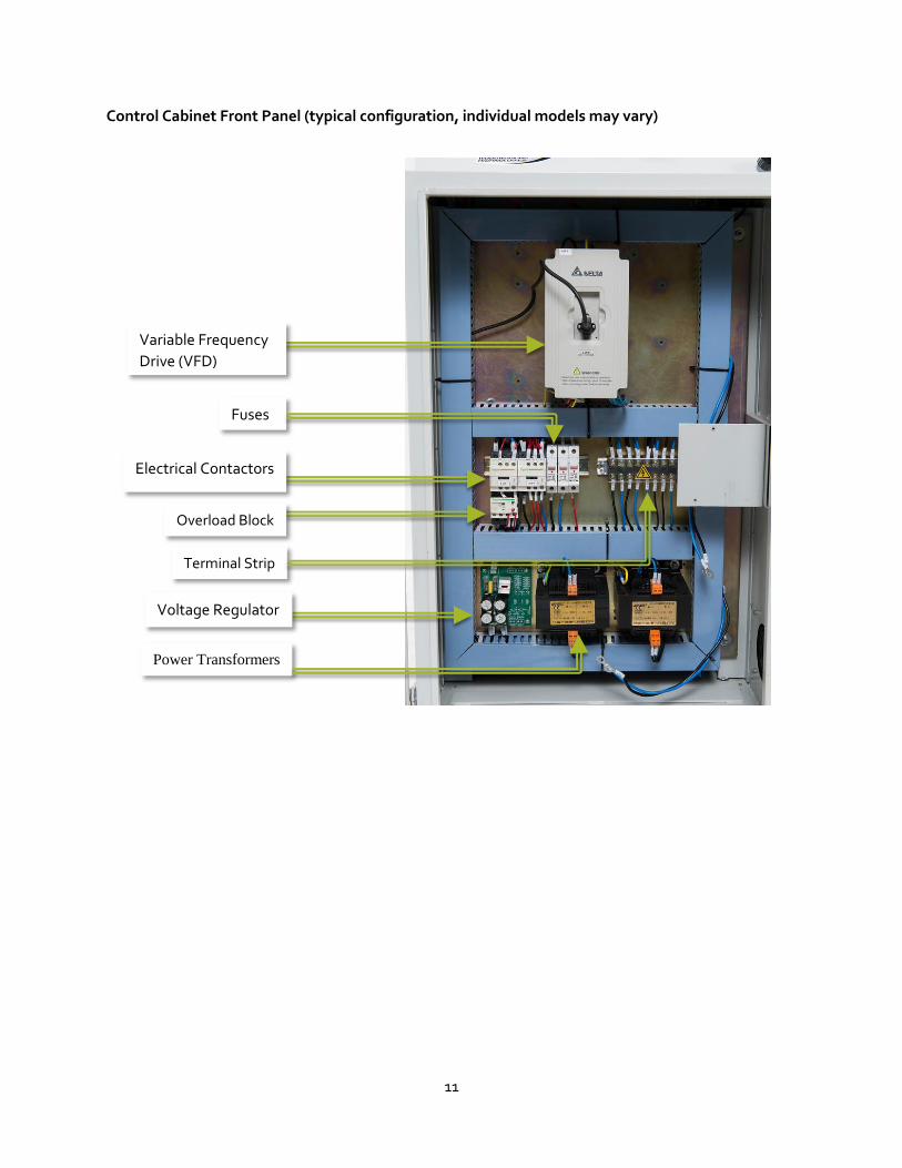
Control Cabinet Front Panel (typical configuration, individual models may vary)
Variable Frequency
Drive (VFD)
Fuses
Electrical Contactors
Overload Block
Power Transformers
Voltage Regulator
Terminal Strip

12
Control Cabinet Rear Panel (typical configuration, individual models may vary)
Connecting the hand held controller to the cabinet.
The cable that connects the hand held controller must be fed through the front panel of the control cabinet. To do this,
Remove the four screws that secure the cover and set them aside in a safe place.
Lift off the cover from the control cabinet to expose the interior.
Remove the four screws that fasten the reducer plates to the square opening on the front of the control cabinet and set the screws aside with the others.
Pass the connector through the opening leaving about a foot or so to coil up in the cabinet.
Coil the cable in a small loop and fasten it with a few cable ties. This will provide some strain relief if the cord is accidentally pulled.
Plug the connector into the socket on the controller module and tighten the two set screws on either side of the connector.
Fit the rubber strain relief connector to the cable where it passes through the panel and with the lock-nut on the inside portion of the cable, re-install the two reduction plates in the front panel to close the opening.
Weihong NK105
Control Module
Y-Axis Controller
Controller Power Supply
Y-Axis Controller
Z-Axis Controller
Terminal Strip

13
Insert the strain relief connector and tighten the plastic lock-nut.

14
Connect the power. The Basic 4.4 & 4.8 requires a 220-volt power source. It generates the three phase power the spindle requires via the Variable Frequency Drive. The Basic 4.4 & 4.8 is designed to be hardwired via a disconnect switch to a 20 amp circuit. Follow all applicable local electrical codes. If you do not have this power available in a dedicated circuit in your shop, consult a qualified electrician to install a circuit exclusively for this machine.

15
Hand Held Remote
All machine functions are accessed through the keypad on the handheld remote control. The following
pages outline the function of each key. Some functions will require you to hold the shift key while
selecting a function and these are outlined in the second table.

16
NK105 Control System Individual Panel Keys and Functions
Control Key Key Name Function
Override+ Override to increase federate
Input of number 7
Increase of spindle gear with the help of auxiliary key when spindle port has input
Y+ Positive shift of Y Axes
Input of number 8
Switch between MCS and WCS with the help if the auxiliary key
Z+ Positive shift of the Z Axes
Input of number 9
X- Negative shift of X Axes
Input of number 4
Return to the mechanical origin with the help of the auxiliary key
Spindle Start/Stop
Start or stop the spindle under manual mode Input of the number 5 Return to work-piece origin with the help of the auxiliary
key
X+ Positive shift of X Axes
Input of number 6
Override - Override to decrease feed rate
Input of number 1
Decrease of spindle gear with the help of auxiliary key when spindle port has input

17
Y- Negative shift of Y Axes
Input of number 2
Z- Negative shift of Z Axes
Input of number 3
Speed Switchover
Switch between manual low/high speed
Input if number 0
Tool pre-setting with the help of the auxiliary key
Return to Origin
Return to the origin of X and Y Axes
Input of minus
Return to the origin of the Z Axis with the help of the auxiliary key
Menu Entering the menu page
Input of decimal point
Entering image update page at the time of system start up.
Start Start key
Breakpoint resume with the help of the auxiliary key
Up Suspend processing
Up direction key
ESC Stop processing
Cancelation of various selections, inputs and operations
Shift Auxiliary key

18
Down Down direction key
OK Entering manual high/low speed adjustment page under menu page
Confirmation of various selections, inputs and operations

19
NK105 Control System Combination Panel Keys and Functions
To access these functions, you will need to press the ‘Shift” key in addition to the function key.
Keys Function
+
Increase of spindle gear
+
Switch between MCS and WCS
+
Return to mechanical origin
+
Return to work-piece origin
+
Decrease of spindle gear
+
Floating pre-setting
+
Z Clear

20
+
Break-point resume
+
Enter help page

21
Quick Start Guide
Action Connect the machine to a properly rated electrical supply. Release the emergency stop button if required by giving it a twist to the right until it pops out.
When connected to a live circuit, the lamp in the ‘POWER OFF” button will be lit. This indicates that there is power to the system and it is ready to be turned on.
To power up the system, press the green power ‘POWER ON’ button. The green ‘POWER ON’ button will illuminate and the red ‘POWER OFF’ lamp will go out.
When power is applied to the system, the CPU will boot up and the home screen for the Weihong control system will be displayed as the controller boots up.
A second Weihong home screen will be displayed during the boot process.
The CPU will search if there is a USB thumb drive installed. It will move on to the next screen automatically.
After checking for the USB drive, the machine will ask for the spindle to be returned to the reference point. Press ‘OK’ and the machine will move to the home position and engage the limit switches.

22
When the spindle has finished the homing process, the controller will want to load a file. To load a file from the USB drive, press ‘OK’
The tool-path files available on the USB drive will be displayed on the screen. To see any additional files, use the ‘UP’ and ‘DOWN’ buttons to scroll through the list.
Highlight the file you want by using the ‘UP’ and ‘DOWN’ buttons and then press enter to select it. To load the file into memory press ‘1’
Depending on the size of the file, you may see a status screen displaying the load progress. When the file has loaded, the screen will show the current spindle position as well as some additional information on the right. At this point, the file is ready to run.
Install and set the tooling as required by the loaded tool-path program (see Setting The Tool Length in the next section)
Perform a test if you are unsure of the result. Set the Z=0 point to a location above the work-piece so the bit is in free air and run to program to observe the result.

23
Setting the tool length
The Basic 4.4 & 4.8 CNC allows you to automatically set the length of the tooling using the tool setting
device. Install the tooling required into the collet and use the two wrenches to tighten the collet nut.
Ensure that the controller is in slow jog mode and carefully move the bit down the Z axis so it is just above the top of the brass button on the tool setting device.
With the tool setting device directly beneath the bit and press the shift and ‘0’ key. The bit will begin to move down and when the tip makes contact with the brass button on the tool setting device it will complete an electrical circuit that will register the location of the bottom of the bit.
After the tooling makes contact and electrical circuit as been completed it will retract to a pre-programmed distance above the workpiece and stop.
The tool is now calibrated and is now ready to run.
The automatic tool setting function uses an electrical signal to set the tool length. When the cutting edge of the bit contacts the touch off puck it will complete an electrical circuit which stops the bit and sets Z=0. To ensure the proper functioning of this feature, it is important that there be no electrical conductivity between the touch off puck and the machine frame. Touching the frame as well as the brass puck during the operation of the automatic tool-setting feature will cause unreliable operation that will damage the brass puck or the bit. Having the dust extraction system connected and operation will cause static electricity to interfere with the operation of this circuit. After machining some resinous materials a non conductive barrier may build up on the edge of the cutter; this prevent the electrical circuit from closing and defeat the operation of the tool setting feature.
The Tool setting device features a spring loaded touch off button. If the circuit fails to operate correctly
because of environmental conditions, the center is spring loaded and an electrical contact will
physically interrupt the circuit to avoid any potential damage.
You can also set the tool length using the following procedure.
Using the jog function (Slow mode), move the spindle close to the surface of the material.
Place a piece of paper on the surface of your material and switch the hand held remote to stepping mode.
Use the ‘Z=-‘key to step the bit down until it contacts the piece of paper.
Press the shift and ‘Z=0’ key to reset the Z=O value
The system will confirm your request.
Press the OK key to confirm.

24
Exiting the System and Power Down The CNC machine is computer controlled and to prevent problems it is important to exit the control system in the proper manner. Failure to follow this procedure could generate error codes. If you simply press the power off button, one of the error codes you may see when you next start the machine is ‘Previous shut down was illegal’. To avoid potential problems and the corruption of your data, follow this procedure.
Press the menu key to display options
Scroll down to option ‘7’, ‘System Upkeep’ and select
Scroll down to option ‘7’, ‘Exit’ and select
Press ‘OK’ to exit the system and the screen will go blank and the system will be ready to power down.
Press the red power button on the main control cabinet to shut the system down
If you wish to re-enter the control system you will need to cycle the power to restart the controller

25
Typical CNC Project Workflow
Concept Stage
This is the initial design stage of any CNC project. Your project may begin as a sketch, a request from a
customer or a detailed drawing from a designer. At the concept stage, you can receive your design
criteria from any number of sources. This is the make or break stage of the project, the part of the
process where the creative input is co-ordinated with the realities of the production process. Elements
of the design may not be easily executable with your available machine and tooling so this is the time to
revise the design to accommodate your available resources. You may not be able to cut tight radius
corners with your available cutters for example. This is also the time to consider the material you will
use, where the item is to be used (indoors or out) and any joinery that may need to be cut. You will
need to prepare the thickness of your material accurately if the CNC machine is to cut joinery that will
allow your parts to slot together.
Design Stage
When you have a fully realized concept, you are ready to move on to the design stage and the CAD
process. Open your CNC software and begin by specifying the size of the material you will be working
with. At this time you will also specify the X,Y and Z origin points on your virtual part. When it comes
time to machine the part on the CNC, you will set these co-ordinates in the real world on the bed of the
machine. At this stage, you will also define the measurement units you are going to be using. (mm vs.
inch). You can use your software package to create your vectors or you can import them from another
program. At this stage, you can incorporate features that will aid in later production stages. For
example, you can cut slight pockets for hardware to help properly locate it during assembly or you
could mark the locations of hand-drilled holes with a dimple. Consider all aspects of the project
production during the design stage; small steps taken now can result in major timesavings and
increased accuracy later.
Tool Path Generation
After you have completed the design process and have a complete set of vectors to work with it is time
to generate the tool-path. It is best to reconfirm your material dimensions before continuing.
Begin by selecting the type of tool-path you wish to use. Most software packages offer a number of different tool-path options: pocket, drilling, v-carve and profiling to name a few. The function of each of these different tool-path options will be described in detail in the documentation that accompanies the software you are using.
Select the type of cutter that is best suited to machine the chosen profile in the material you are using. Because of their nature, some tool-paths are limited to using certain types of cutters and this will become evident in the software you are using. Some options will be visible in the menu but not available to use. The software will store a library of tool choices and you will need to

26
make sure that the tool you are using matches the specifications for that cutter in the tool file. Adjust any discrepancies in the tool file or create a new tool file for that cutter.
Select and define any other options for that specific tool-path. Items such as feed rate can be defined and depending on your model, speed control might be available as well. For example, when running a profile tool-path to cut out parts from a larger piece, you can set tabs that will hold everything together during the machining process. Once complete the parts can be removed from the grid and the tabs sanded flush.
Calculate the tool-path and run a simulation. After you calculate the tool-path, use the preview function to view the result of the selected tool-path on the screen. This will allow you confirm that the piece has been cut according to your intentions and this is the time to correct any mistakes as they should be visible. If it does not look right during the preview, it will not be right during the cut.
Save your tool-path(s) to your hard drive in a tool-paths folder. Each brand of CNC controller will require that the tool-path be configured so it will understand the information. The Weihong Controller used in the Basic 4.4 & 4.8 Series needs to be saved with the “.nc easy” post processor.
Machining For the machining part of the operation to faithfully reproduce what you worked to achieve in the
simulation, you will need to properly re-create the all of the conditions of the simulation on the bed of
the machine. This involves several steps which you must go through in order to achieve success.
Begin by transferring the tool-path file to the machine. Open the tool-paths folder on your computer’s hard drive, select the appropriate file(s) and then copy the file(S) to the USB drive.
Insert the USB drive into the USB port on the front of the Basic 4.4 & 4.8 CPU Cabinet. On the hand-held remote press the menu key and select the USB drive option. Scroll down to the file you want to select and press the enter key. This will place a check mark beside the file. With the file selected, you then press the “load’ button and the file will load into the memory.
Load the material onto the machine. You will need to use some form of hold down to secure the material while it is being machined. For more detailed information on the various options, see the chapter on fixturing. It is extremely important to ensure that the clamping mechanisms are clear of the tool-path you will run. If any part of the bit or spindle comes into contact with the clamping mechanism you will damage the bit, spindle, clamp and material. If in doubt, set your Z=0 point to a value above the surface of the material and run the program to check for any conflicts.
Set the Material Co-ordinate system to reflect the same value as the simulation. Using the jog and step functions on the hand held controller, position the center of the spindle over the origin point in the X and Y axis. If you are using a bit that has a natural center point, this will be relatively simple to do visually. If you are using a large flat bottomed one, use another bit that comes to a point to properly locate this point. A 60 degree V groove bit is an excellent choice for this task.
Insert the collet into the collet nut so that it is held captive. Begin to thread the collet nut onto the spindle arbor one turn. Insert the tooling into the collet. Be sure the bit is not inserted to deeply or dust and debris will work its way up into the collet. When the bit has been properly seated in the collet, tighten the nut with the two wrenches. For more detailed information, see the section on collets.

27
Ensure that the bit you are using has the same characteristics as the bit that you used during the simulation. If any of the critical values are different then your result will not match the simulation.
Set the length of the bit either automatically or manually. See the previous chapters for details.
STOP. LOOK AND THINK. Before you proceed and turn on the machine to run the program, take a look at your set up with a critical eye. Has the material been loaded correctly and secured properly without any tool-path conflicts? Has the right tool been installed and calibrated. Has the work-piece origin been set correctly? Have all foreign objects been removed from the table?
Ensure that an adequate time has been programmed into the tool-path to allow the spindle to come up to speed before the cutting starts. If the spindle is not at the proper speed when it begins cutting you will not get an optimum cut and could possibly damage the bit or material. If there is not enough time, change the value on the Weihong Controller. A quick short-cut is to back the gantry to the far end of the table to ensure that the spindle is spinning at the proper RPM by the time it gets to the start point of the cutting operation.
Finishing Finishing is the final step in the process. The sharpness of the cutting tool, the machining characteristics
of the material and the nature of the program will all play a part in the success of the final result.
If you are running a program that executes an intricate carved surface, running the program once may
leave some fuzzy edges. This can often be remedied and your sanding time reduced by running the
program twice.
Even under optimal condition there will be some sanding to do when the part has been finished.
Regular sandpaper is not the most appropriate to sand carved surfaces; you cannot easily sand within
the recesses without sanding off any raised detail and affecting the crisp look. The best way to reduce
the amount of time it takes and maintain the crisp look of the carving is to use a sanding mop. These
are composed of many layers of slotted sandpaper that is stacked on a mandrel. Mount the sanding
mop in a drill press set at 2500 rpm and pass the carved work over the mop. It will sand any rough areas
and prepare the part for finishing in very little time.
Another area that can be a problem with the carved areas crops up during the finishing process. When
you apply a finish with a brush or a rag it is natural that as the applicator is dragged over the rough
areas, the finish will be pulled off the applicator as it meets the edge of the carving. This excess finish
will then run down the edge and pool at the bottom of the carving. It is best to use an HVLP system to
carefully apply several thin coats of any film forming finish. If you are using a wipe on finish such as a
Danish Oil, you can generously apply the finish with a cloth and then use compressed air to blow the
excess finish out of the recesses. Observe all compressed air safety precautions and wear eye
protection.

28
Collet and Tooling Installation
Select the proper size collet for the bit you will be using. Using the wrong size collet will not allow the
collet to properly grip the bit; this will result in damage to the collet, bit and work piece. Do not insert
the bit into the collet and then try to seat it in the nut; if the bit is inserted in the collet first, the collet
will not be able to compress in order for the locking ring in the nut to engage.
To insert the collet into the nut, place the collet on a solid stable
surface with the arbor end down. Place the collet nut on top of
the collet so it sits level.
Using the palm of your hand, apply
slight downward pressure to the
nut until you hear and feel the ring
in the collet engage with the raised
ridge on the collet nut.
When the collet has been properly
inserted it will be held captive by the nut and the face of the
collet will be level with the face of the nut.
Loosely thread the nut/collet assembly onto the spindle. If you
experience difficulty starting the thread, slowly spin the nut
backwards until you feel it seat itself on the thread and then
turn it in the forward direction just enough to hold it in place.

29
Insert
the
tooling into the collet ensuring that it is fully seated. Most of the shank should be engaged in the
holder. If you insert the bit too deeply into the collet you could end up getting the flutes or chip
clearance areas below the surface of the collet. This will allow dust and fine chips to penetrate up into
the collet.
Improperly Inserted Bit
Bit inserted to the correct depth.

30
To remove the collet from the collet nut, first remove the bit and
then place the assembly face down on a solid surface.
Use your thumb on the collet nut and the side of your index finger
on the other side of the collet and squeeze. By applying pressure at
an angle like this, the collet will pop it out of the retaining ring in the
nut.

31
A clean collet is a happy collet.
Inspect your collets every time you change the bit. As the machine works, fine dust will work its way
into the collet grooves. After removing the bit, thoroughly inspect and clean the collet. Any dust that
remains in the collets groves will prevent it from compressing properly on the shaft of the bit. This dust
can easily be removed with an old tooth-brush or a brass brush and some compressed air. Observe
proper compressed air safety protocols. Pipe cleaners are an excellent way to clean the inside of the
collet. If the inside of the collet is not cleaned, material can build up and cause run-out and this will
affect the result.
Replace worn collets.
When collets are worn they will not compress properly and hold the bit securely. A collet should be
replaced every 400-800 hours of use.

32
Fixturing
A CNC machine is a very accurate and efficient woodworking machine. For the CNC machine to do its
work, the material it is working on must be held securely. Additionally, the hold down mechanism must
be clear of, and not interfere with any portion of the spindle or dust collection hood during the program
execution. ‘Fixturing’ is the term used to refer to the hold down mechanisms employed on a project.
This should be a consideration right from the projects earliest planning stages. Planning an efficient
hold down strategy is especially critical in a production environment as this will reduce turn-over time
between parts.
Two Sided Adhesive Tape Two sided tape is available at almost every
hardware and building supply outlet.
There are several types available both
with and without reinforcing fibres. When
using two sided tape, be sure to apply the
tape evenly around the perimeter. The
tape has a certain thickness and you need
to support the entire work-piece evenly.
Failure to apply the tape properly may
allow the material to move when the
spindle tries to cut or press down on an
unsupported portion of the material. If
you are cutting the part out, be sure to
keep the adhesive tape away from the
tool-path. If the cutter cuts through the
tape, it will get gummed up and the rest of
the cut will be affected. For two sided
tape to provide proper adhesion, both the
work-piece and table must be free of dust. Apply the tape to the work-piece and then position it on the
spoil-board. Us a sacrificial piece of MDF as a cushion and tap the material gently to set it in place. Do
not leave a part attached to the spoil-board overnight. The adhesives on some brands will strengthen
over time and if you leave attached overnight then you risk removing some of the surface of your spoil-
board.

33
Screws (Nested parts) When cutting a number of parts out of a larger sheet of material, have your CAD/CAM lay out the
nested parts. Once you have determined which layout to use, plot a number of holes in the waste area
of the material and calculate a tool-path to drill these. Load the material into the machine and then run
the drilling tool-path. Once complete, fasten the material to the spoil-board using screws and then run
the remaining tool-paths.
T-Tracks & Clamps
The Basic 4.4 & 4.8 ship with an aluminum T-Track table
top. These slots allow you to use a number of different
clamping mechanisms that are designed to accommodate
T-Track fixtures. If you use a spoil board then these slots
can be used to hold down the spoil board. Use a spoil board
anytime you will be cutting through the material or the bed
will be damaged. If you are only working on the surface of
the material then you can use the T-Track slots in
combination with the supplied clamping fixtures to hold the
part down. When using any hold down, be sure that it is
clear of any tool-path travel required to machine the part. If the spindle and bit come into contact with
the metal clamping mechanism damage will occur. If in doubt, set your Z=0 start point to a positive
value above any obstructions and run the program and observe the result.
Job Specific Jigs Certain jobs may require you to make specialized hold down fixtures. This can easily be done using
your CAD/CAM software by utilizing vector
elements of the item to be held down. For
example, let’s take a look at a situation
where you want to be able to make
multiple copies of the same part, a push
stick for the table saw. In this case, the
part is being made from a piece of ½” thick
MDF. When cutting these form a larger
sheet, you could set up the v-groove
tooling for the caving, perform that
operation and then swap tooling and to do
the profile cut out. To carve the other side means you will have an irregular work-piece to secure
repeatedly in the same location. When making multiple parts, swapping the bits during the machining
of each part would involve a lot of extra time and work. In this case it is more efficient to produce all of
the parts from your stock in one operation and then carve the detail in a second operation and then flip
the cut parts over and carve the second side. The obvious downside to this is that it leaves you a very
irregular object that needs to be held down precisely in the right location for the next stage of the
34
operation to succeed. Because of the design, using hold down clamps is not an option as they would,
by their nature interfere with the cutter. Using clamps that apply pressure to the side of the part would
be an option but this still leaves you with the need to precisely position this part relative to the virtual
block of wood it was machined from. In this situation it is convenient to go back to your CAD/CAM
software and use the vectors that defined the cut-out part to define a holder to secure the part for the
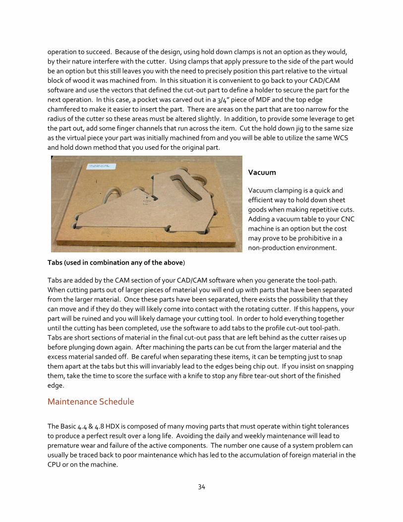
next operation. In this case, a pocket was carved out in a 3/4” piece of MDF and the top edge
chamfered to make it easier to insert the part. There are areas on the part that are too narrow for the
radius of the cutter so these areas must be altered slightly. In addition, to provide some leverage to get
the part out, add some finger channels that run across the item. Cut the hold down jig to the same size
as the virtual piece your part was initially machined from and you will be able to utilize the same WCS
and hold down method that you used for the original part.
Vacuum Vacuum clamping is a quick and
efficient way to hold down sheet
goods when making repetitive cuts.
Adding a vacuum table to your CNC
machine is an option but the cost
may prove to be prohibitive in a
non-production environment.
Tabs (used in combination any of the above) Tabs are added by the CAM section of your CAD/CAM software when you generate the tool-path.
When cutting parts out of larger pieces of material you will end up with parts that have been separated
from the larger material. Once these parts have been separated, there exists the possibility that they
can move and if they do they will likely come into contact with the rotating cutter. If this happens, your
part will be ruined and you will likely damage your cutting tool. In order to hold everything together
until the cutting has been completed, use the software to add tabs to the profile cut-out tool-path.
Tabs are short sections of material in the final cut-out pass that are left behind as the cutter raises up
before plunging down again. After machining the parts can be cut from the larger material and the
excess material sanded off. Be careful when separating these items, it can be tempting just to snap
them apart at the tabs but this will invariably lead to the edges being chip out. If you insist on snapping
them, take the time to score the surface with a knife to stop any fibre tear-out short of the finished
edge.
Maintenance Schedule
The Basic 4.4 & 4.8 HDX is composed of many moving parts that must operate within tight tolerances
to produce a perfect result over a long life. Avoiding the daily and weekly maintenance will lead to
premature wear and failure of the active components. The number one cause of a system problem can
usually be traced back to poor maintenance which has led to the accumulation of foreign material in the
CPU or on the machine.

35
Daily
Blow the dust of off the working parts of the machine at the start of every day.
Spray the non-painted working parts such as the rails and lead screws with a thin lithium or
Teflon lubrication spray.
Run the machine through the full range of motion in the X, Y and Z axis to confirm trouble free
operation.
Check the condition of your cutters prior to use. Clean, sharpen or replace as required.
Lubricate the guide rails and lead screws every 10 hours of operation or at the end of the day,
which-ever comes first.
Clean all the dust off the rail and lead screws at the end of the day. Wood dust absorbs ambient
moisture and this will lead to the formation of rust on these parts. Lubricate these parts after
cleaning to provide additional protection
Weekly
Inspect the machine for any loose parts and retighten as required.
Inspect the rails and lead screws closely for any wear or damage.
Clean and lubricate the rails and lead screws.
Confirm that the dust extraction connection is functioning properly.
In a dusty environment, open the CPU case and use compressed air to clear any dust that may
have accumulated inside.
Monthly
Open the CPU case and use a vacuum to clear any dust that may have accumulated inside.
Inspect the connections at the back of the CPU cabinet to ensure the retaining nut is tight.
Inspect all connections at the gantry to ensure they are secure.

36
Definitions
2D A tool-path to make a single depth cut of the selected design. The bit is moved along the tool-path in the ‘x’ and ‘y’ axis while the ‘z’ value remains constant.
2.5D A tool-path that that follows the edge of a vector, the depth of cut being determined by the width of the vector and the geometry of the bit.
3D Full three-dimensional modeling of objects.
Ball Nose Bit A carving bit with a rounded tip that allows for smooth machining of complex forms.
CAD Computer Aided Design. This is a software package that allows you to create a virtual design of your item on the computer. By designing the part on the computer it will be easy to modify the design at any point if required
CAM Computer Aided Manufacturing. This is the other side of the CAD/CAM software package. It will take the computer-generated design and allow you to define tool-path and milling operations and convert it into a language that the CNC machine will understand.
CNC Computer Numeric Control. A system that allows for the control of a machine using a stream of digital information generated via a computer.
DXF Abbreviation for Design Exchange File, a two-dimensional graphics file format supported by all PC based CAD products. Autodesk created it for the AutoCAD system.
MCS Material Co-ordinate system. This is the co-ordinate system that is defined when you set the X and Y axis to 0;0. It defines the origin point of the virtual part in the real world on the bed of the machine.
M Code
Ref Point The home position of the machine as defined by proximity switches.
Spoil Board A sacrificial surface fastened to the CNC table to allow through cuts that would damage the bed of the machine.
Vector A two dimensional line having length and width.

37
Troubleshooting Guide
Problem Action
Machine does not turn on
Ensure the Emergency Stop Switch has not been engaged. To release it, give it a spin to the right The red light should now come on.
Use a voltage tester to confirm that the correct electrical supply is available.
Consult a licensed electrician to provide the appropriate point of attachment. NEMA 6-15R
Confirm that the hand held remote connector has been properly and securely installed.
Unplug the power and remove the two line fuses from the F1 (see CPU cabinet breakdown) Check to see if these have continuity across them. If they are blown, inspect the control wiring and components for apparent damage. Replace the fuses and apply the power.
CPU line fuses keep blowing
Inspect wiring in the CPU cabinet for damage, loose connections and short circuits. Heat damage will manifest as a discolouration in the wires insulation. This can indicate a loose connection that has been subjected to a sustained heavy load or rapid start stop cycle.
Excessive vibration Machine is has not been properly leveled. Adjust the levelling mechanisms between bed of the machine and the stand as well as between the stand and the floor.
If there are many small plunge cuts with movement in the X/Y axis, the machine will begin to shake if you attempt to execute the program too rapidly. Slow the speed down using the hand held remote until the vibration stops.
Spindle does not rotate
Spindle gears not properly programmed on the Variable Frequency Drive. Compare parameters 17 through 23 with the VFD Initial Settings Chart.
Damaged VFD – if the Variable Frequency Drive has been damaged. It will display an error code that will allow further diagnostics beyond the scope of this manual.
Spindle Slows Down
Speed value programmed incorrectly in the tool-path.
Density changes in the material along the tool-path. Reduce operating speed.
Cutting edges have become dull and need to be sharpened.
Feed rate and depth of cut too great for the cutter and material. Slow down the feed rate or reduce the depth of cut.
Variable Frequency Drive Fault. See error code on the drive.

38
Poor Quality of cut Cutting edges have gummed up and need to be cleaned.
Cutting tool is dull. Sharpen or replace the cutter.
Cut speed is too rapid for the material being cut. Adjust the speed to achieve optimum results for each type of material. Keep a record of your results for future reference.

39
VFD Initial Settings Chart
# Parameter MK HDX
00 Source of Frequency Command 00
01 Source of Operation Command 01
02 Stop Method 00
03 Maximum output frequency 300.0
04 Maximum Voltage Frequency (base Frequency)
300.0
5 Maximum Output Voltage (Vmax) 220.0
6 Mid-Point Frequency 1.5
7 Mid-Point Voltage 10
8 Minimum Output Frequency 1.5
9 Minimum Output Voltage 10
10 Acceleration Time 1 10
11 Deceleration Time 1 10
12 Acceleration Time 2 10
13 Deceleration Time 2 10
14 Acceleration S-Curve 00
15 Jog Acel/Decel Time 1.0
16 Jog Frequency 6.00
17 1st Step Speed Frequency 300.0
18 2nd Step Speed Frequency 25.00
19 3rd Step Speed Frequency 250.0
20 4th Step Speed Frequency 150.0
21 5th Step Speed Frequency 100.0
22 6th Step Speed Frequency 50.00
23 7th Step Speed Frequency 0.00
24 Reverse Operation Inhibiton 01
25 Over Voltage Stall Prevention 390.0
26 Over-Current Stall Protection during Acceleration
150
27 Over-Current Stall Prevention During Operation
150
28 DC Braking Current Level 00
29 DC Braking Time During Start-up 0.0
30 DC Braking Time During Stopping 0.0
31 Start Point for DC Braking 0.00
32 Momentary Power Loss Operation Selection
00
33 Maximum Allowable Power Loss Time 2.0
34 Base-Block Time for Speed Search 0.5

40
35 Maximum Current Level for Speed Search
150
36 Upper Bound of Output Frequency 400
37 Lower Bound of Output Frequency 0.00
38 Multi-Function Input Terminal (M0, M1) 00
39 Multi-Function Input Terminal (M2) 05
40 Multi-Function Input Terminal (M3) 06
41 Multi-Function Input Terminal (M4) 07
42 Multi-Function Input Terminal (M5) 08
43 Analog Output Signal 00
44 Analog Output Gain 100
45 Multi-function Output Terminal 1 (Photocoupler Output)
00
46 Multifunction Output Terminal (Relay Output)
07
47 Desired Frequency Attained 0.00
48 Adjust Bias of External Input Frequency 0.0
49 Potentiometer Bias Polarity 00
50 Potentiometer Frequency Gain 100.0
51 Potentiometer Reverse Motion Enable 00
52 Motor Rated Current 7.0
53 Motor No-Load Current 2.8
54 Torque Compensation 00
55 Slip Compensation 0.00
56 Reserved 00
57 Rated Current Display of the AC Drive 7.0
58 Electronic Thermal Overload Relay Selection
02
59 Electronic Thermal Motor Overload 60
60 Over-Torque Detection Mode 00
61 Over-Torque Detection Level 150
62 Over-Torque Detection Time 0.1
63 Loss of ACI (4-20mA) 00
64 User Defined Function For Display 00
65 Coefficient K 1.00
66 Communications Frequency 0.00
67 Skip Frequency 1 0.00
68 Skip Frequency 2 0.00
69 Skip Frequency 3 0.00
70 Skip Frequency Band 0.00
71 PWM Carrier Frequency 15
72 Auto Restart Attempts After Fault 00

41
73 Present Fault Record 00
74 Second Most Recent Fault Record 00
75 Third Most Recent Fault Record 00
76 Parameter Lock and Configuration 00
77 Time For Auto Reset the Restart Times after Fault
60.0
78 PLC Operation Mode 00
79 PLC Forward/Reverse Motion 00
80 Identity Code of the AC Motor Drive 04
81 Time Duration of 1st Step Speed (correspond to #17)
00
82 Time Duration of 2nd Step Speed (correspond to #18)
00
83 Time Duration of 3rd Step Speed (correspond to #19
00
84 Time Duration of 4th Step Speed (correspond to #20)
00
85 Time Duration of 5th Step Speed (correspond to #21)
00
86 Time Duration of 6th Step Speed (correspond to #22)
00
87 Time Duration of 7th Step Speed (corresponds to #23)
00
88 Communications Address 01
89 Transmission Speed (Baud Rate) 01
90 Transmission Fault Treatment 03
91 Time Out Detection 0.0
92 Communication Protocol 00
93 Accel 1 to Accel 2 Frequency Transition 0.00
94 Decel 1 to Decel 2 Frequency Transition 0.00
95 Auto Energy Saving 00
96 Count Down Completion 00
97 Preset Countdown Completion 00
98 Total Time Count From Power On (Days) Read Only
99 Total Time Count From Power On Read Only
100 Software Version Read Only
101 Auto Acceleration/Deceleration 00
102 Auto Voltage Regulation (AVR) 00
103 Auto Tune Motor parameters 00
104 R1 Value 00

42
105 Control Mode 00
106 Rated Slip 3.00
107 Vector Voltage Filter 10
108 Vector Slip Compensation Filter 50
109 Selection For Zero Speed Control 00
110 Voltage of Zero Speed Control 5.0
111 Deceleration S-Curve 00
112 External Terminal Scanning Time 01
113 Restart Method After Fault 01
114 Cooling Fan Control 02
115 PID Set Point Selection 00
116 PID Feedback Terminal Selection 00
117 Proportional Gain (P) 1.0
118 Integral Time (I) 1.00
119 Differential Time (D) 0.00
120 Integrations Upper Bound Frequency 100
121 One Time Delay 0.0
122 PID Frequency Output Command Limit 100
123 Feedback Signal Detection Time 60.0
124 Feedback Signal Fault Treatment 00
125 Source of PID Set point 0.00
126 PID Offset Level 10.0
127 Detection Time of PID Offset 5.0
128 Minimum Reference Value 0.0
129 Maximum Reference Value 10.0
130 Invert Reference Signal AVI (0-10V) 00
131 Minimum Reference Value (0-20mA) 4.0
132 Maximum Reference Value (0-20mA) 20.0
133 Inverts Reference Signal (0-20mA) 00
134 Analog Input Delay Filter for Set Point 50
135 Analog Input Delay Filter for Feedback Signal
05
136 Sleep Period 0.0
137 Sleep Frequency 0.00
138 Wake Up Frequency 0.00
139 Treatment for Counter Attained 00
140 External up/Down Selection 00
141 Save Frequency Set Point 01
142 Second Source of Frequency Command 00
143 Software Braking Level 380.0
144 Accumulative Motor Operation Day Read Only

43
145 Accumulative Motor Operation Time (min)
Read Only
146 Line Start Lockout 00
147 Decimal Number of Accel/Decel Time 00
148 Number of Motor Poles 04
149 Gear Ratio for simple index function 200.0
150 Index Angle for Simple Index Function 180.0
151 Deceleration Time for Simple Index Function
0.00
152 Skip Frequency Width 0.00
153 Bias Frequency Width 0.00
154 Reserved 00
155 Compensation Coefficient for Motor Instability
0.0
156 Communication Response Delay Time 00
157 Communications Mode Selection 01
44
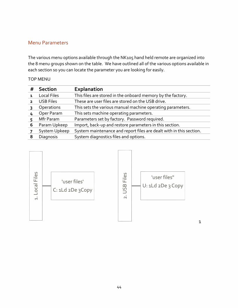
Menu Parameters
The various menu options available through the NK105 hand held remote are organized into
the 8 menu groups shown on the table. We have outlined all of the various options available in
each section so you can locate the parameter you are looking for easily.
TOP MENU
# Section Explanation 1 Local Files This files are stored in the onboard memory by the factory.
2 USB Files These are user files are stored on the USB drive.
3 Operations This sets the various manual machine operating parameters.
4 Oper Param This sets machine operating parameters.
5 Mfr Param Parameters set by factory. Password required.
6 Param Upkeep Import, back-up and restore parameters in this section.
7 System Upkeep System maintenance and report files are dealt with in this section.
8 Diagnosis System diagnostics files and options.
1
1. L
oca
l File
s
'user files'
C: 1Ld 2De 3Copy
2. U
SB
File
s
'user files"
U: 1Ld 2De 3 Copy

45
3. O
per
atio
ns
1. Back REF Point
1. All Home
2. Z Home
3. X Home
4. Y Home
2. Rect Machining
1. Params SettingEngrDpth, EachDpth, ToolDia, NoseGap, Height,
Width, X Init, Y Init, Mode Horiz. Mill
2. Load The Last
3. Select Line NoTotal, StartLine, Endline
---Execute Now---
4. Machining Info
---Parsing...---
Time 0:0:0
X;, Y:, Z:
5. Park MCS Site
1. Park ModeNot Move, To park site, To WCS Origin
---[OK] Select---
2. Park Site
1. Input SiteInput Park Site
X:'0,0', Y:'0,0', Z:'0,0'
2. Select SiteSet current pos as park
pos. by [OK] key, return by [ESC] key
6. Select WCS SiteG54 WCS. G55 WCS, G56 WCS, G57 WCS, G58 WCS, G59 WCS
---Select by [OK] key---
7. Array ProcessFile, Rows, Collumns, RowSpace, ColSpace, Delay
---Execute Now---

46
4. O
per
Par
am1. G00 speed
Spec.: G00 speed
Value:, Unit: mm/min
2. Gxx SpeedSpec.: G00 speed
Value:, Unit: mm/min
3. Back REF First
Spec.: Back REFP
Before machinintg
Value: Yes, Unit:
4. Lifts on Pause
Spec.: * lifting
height at pause
Value: 10.000, Unit: mm
5. Offset
1. PublicOffsetPublicOffset
X Axis:, Y Axis: Z Axis:
PublicOffset
X Axis: x.xxx
Y Axis x.xxx
Z Axis: X.xxx
2. Work Offset1. thru 6.
G54 thru G59 Offset
ex. G54 Offset
X Axis: xxx.xxx
Y Axis: xxx.xxx
Z Axis: xxx.xxx
6. Cycleprocess
1. Cycle Process
Spec.: Enable Cycle Process
Value: yes/no
Unit :
2. Cycle Times
Spec.: Cycle Times
Value:Unit :
3. Cycle IntervalSpec.: Interval of Cycle Process
Value: xUnit : ms
4. S_Off in IntevSpec,: SPDL Off In The Interval
Value: NoUnit :
7. G73-G83Retract
Spec.: G73-G83Retract Distance
Value: x.xxxUnit: mm

47
4. O
per
Par
am (c
on
't)
8. Ignore F CodeSpec.: Ignore F Code
Value: YesUnit:
9. Ignore S CodeSpec.: Ignore S Code
Value: YesUnit:
10. SpindleStop
1. SOff at Pause
yes/no
2. SOff at Stop
yes/no
3. SOff at End
yes/no
11. Ratio ON MANUSpec.: *Ratio On In Manu Mode
Value: NoUnit:
12. DXF Params
1. Lifting Height
Spec.: * Lifting Height At G00
Value: x.xxxUnit: mm
2. Process Depth
Spec.: * Process Depth
Value: x.xxx
Unit: mm
3. 1st Point As 0
Spec.: *1st Point As Zero
Value: yes/no
Unit:
4. Shape Process
Spec.: * Process shape separately
Value: No
Unit:
5. Bottom Process
Spec.: * Enable Bottom Machining
Value: yes/no
Unit:

48
4. O
per
Par
am (c
on
't)
12. Dxf Params (con't)
Spec.: * Adopt Metric Size
Value: yes/noUnit:
13. Eng Params
1. Lifting Height
Spec.: * Lifting Height At G00
Value: x.xxx
Unit: mm
2. ToolChangeTip
Spec.: * Enable Tool Change Tip
Value: Yes/no
Unit:
3. Cycle Times
Spec.: * Cycle Process TimesValue: x
Unit:
4. Deep Hole Mode
Spec.: * 0 ; Recip Chip; 1: Recip
Value: x
Unit:
5. Retract Amount
Spec.: * Retract Amount
Value: x.xxx
Unit: mm
6. Select ToolNo.
Spec.: * Process Per Tool No.
Value: yes/no
Unit:
14. Plt Params
1. Lifting Height
Spec.: * Lifting Height
Value: x.xxx
Unit: mm
2. Plt Unit
Spec.: * Plt Unit
Value: xx.xxx
Unit:
3. Tool step
Spec.: * Tool step
Value: x.xxx
Unit: mm
4. Process Depth
Spec.: * Process Depth
Value: x.xxxx
Unit: mm

49
4. O
per
Par
am (c
on
't)
15. Tool Change
1. ATC Capacity
Spec.: * Tool Magazine Capacity
Value: xx
Unit:
2. CurrentToolNo.
Spec.: Set Current Tool No.
Value: x
Unit:
3. Tool Offset
1. thru 10.
Tool1 thru Tool10
ex: Tool Offset 1
X Axis: x.xxx
Y Axis: x.xxx
Z Axis: x.xxx
4. ToolChangeTip
Spec.: Enable Tool Change Tip
Value: No
Unit:
16.ProcessEndTip
Spec.: Red lamp after process
Value: No
Unit:
17. CaliToolHeih
Spec.: Height Aft Calibrate Tool
Value: x.xxx
Unit: mm

50
5. M
FR
Par
am
Input Manufacturer password: _________
6. P
aram
Up
keep
1. Backup ParamsSuccessfully Saved!
OK/ESC
2. Restore BackupSure to restore backup?
OK/ESC
Reboot Immediately?
OK/ESC
3. Factory ParamsRestore Factory Parameters
OK/ESC
4. Export ParamsSuccessfully Exported
OK/ESC
5. Import Params
Imported!
Restart?
OK/ESC

51
7. S
yste
m U
pke
ep1. Language
1. Chinese
2. English
2. Export LogOverwrite Existed Log?
OK/ESC
3. System UpdateUpdate The System?
OK/ESC
4. Register Enter Reg. Code ________
5. Help
Spec.: Help Message Show Delay
Value: x
Unit: s
6. RebootSure To Reboot System?
OK/ESC
7 ExitSure To Exit From System
OK/ESC
8. Delete LogSure to Delete Log File
OK/ESC
9. Disk SpaceDisk Space Left
xxxM/xxxM
10. Delete InfoInfo File Deleted!
OK/ESC

52
8. D
iag
no
sis
1. System Info
1. Software Ver.Sorfware Version
"NK105G2_29_104'
2. Card No.Card Number
WHNC-0105_TDHC-1390
3. Remaining TimeRemaining Time
Limitless
4. Register TimesRegistered Times
x
2. Port ListShift Key Changes assigned
value
3. Keypress Diag
Press A Key:
'displays key value when pressed'
4. Inport Dia Diagnostic Display
5. Outport Diag Diagnostic Display

53
CPU Cabinet Component Schedule

54
Front Panel Control Wiring Schematic

55
Power Distribution Schematic

56
Weihong Controller Wiring Schematic