basic 3 relay instructions - · pdf filebasic relay instructions module 3 3 contacts and...
TRANSCRIPT

M O D U L E T H R E E
3K
ey
Po
ints
➤
BASIC
RELAY
INSTRUCTIONS
So far, you have learned about the components of the MicroLogix 1000PLC, including the CPU, the memory system, the power supply, and theinput/output system. This module teaches you about the control programthat links all of these components together.
There are five sections:
1. Ladder programming
2. Input/contact instructions
3. Output/coil instructions
4. Special programming issues
5. Basic relay programming examples
After finishing this module, you will:
■ understand the basics of ladder programming and the types ofrelay instructions available in the MicroLogix 1000
■ know the two types of contact instructions used to program aMicroLogix 1000, how they operate, and their referenceaddresses
■ know the four basic output instructions commonly used withthe MicroLogix 1000
■ understand key points concerning the ladder scan evaluation,the programming of normally closed input devices, and safetydevice programming
■ be able to apply techniques learned from specific programmingexamples
B a s i c R e l a y I n s t r u c t i o n s
2 Module 3
3-1 Ladder Programming
This section covers the fundamentals of ladder programming. AMicroLogix 1000 uses the control program stored in its CPU toanalyze input data and determine the corresponding output ac-tion. This control program is entered and stored in the CPU asladder diagrams. At the end of this section, you will know:
• the basics of ladder programming
• the two types of relay instructions available in the Micro-Logix 1000
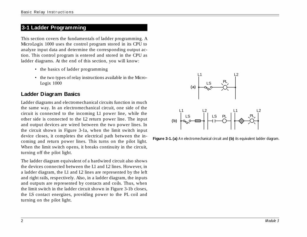
Ladder Diagram BasicsLadder diagrams and electromechanical circuits function in muchthe same way. In an electromechanical circuit, one side of thecircuit is connected to the incoming L1 power line, while theother side is connected to the L2 return power line. The inputand output devices are wired between the two power lines. Inthe circuit shown in Figure 3-1a, when the limit switch inputdevice closes, it completes the electrical path between the in-coming and return power lines. This turns on the pilot light.When the limit switch opens, it breaks continuity in the circuit,turning off the pilot light.
The ladder diagram equivalent of a hardwired circuit also showsthe devices connected between the L1 and L2 lines. However, ina ladder diagram, the L1 and L2 lines are represented by the leftand right rails, respectively. Also, in a ladder diagram, the inputsand outputs are represented by contacts and coils. Thus, whenthe limit switch in the ladder circuit shown in Figure 3-1b closes,the LS contact energizes, providing power to the PL coil andturning on the pilot light.
Figure 3-1. (a) An electromechanical circuit and (b) its equivalent ladder diagram.
PLLS
L1 L2
LS PLPLLS
L1 L2 L1 L2
(a)
(b)
B a s i c R e l a y I n s t r u c t i o n s
Module 3 3
Contacts and Coils. In a ladder diagram, contact instructionsare used to reference input devices and coil instructions areused to reference output devices. A contact examines the stateof its corresponding input field device. It then either energizesor de-energizes, depending on whether the input device is ONor OFF, respectively.
Conversely, a coil energizes or de-energizes according to thestatus of the contacts in its ladder rung. When a coil energizes, itturns its associated output device ON. When a coil de-ener-gizes, it turns its associated output device OFF.
Ladder Rung Structure. In addition to contacts and coils, thereare two other terms used when describing a ladder program:
• rung
• ladder rung matrix
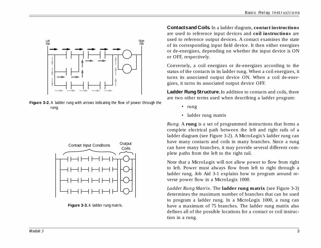
Rung. A rung is a set of programmed instructions that forms acomplete electrical path between the left and right rails of aladder diagram (see Figure 3-2). A MicroLogix’s ladder rung canhave many contacts and coils in many branches. Since a rungcan have many branches, it may provide several different com-plete paths from the left to the right rail.
Note that a MicroLogix will not allow power to flow from rightto left. Power must always flow from left to right through aladder rung. Job Aid 3-1 explains how to program around re-verse power flow in a MicroLogix 1000.
Ladder Rung Matrix. The ladder rung matrix (see Figure 3-3)determines the maximum number of branches that can be usedto program a ladder rung. In a MicroLogix 1000, a rung canhave a maximum of 75 branches. The ladder rung matrix alsodefines all of the possible locations for a contact or coil instruc-tion in a rung.
Figure 3-2. A ladder rung with arrows indicating the flow of power through therung.
Figure 3-3. A ladder rung matrix.
Contact Input Conditons OutputCoils
LeftRail
RightRail
B a s i c R e l a y I n s t r u c t i o n s
4 Module 3
Relay InstructionsRelay instructions form the category of programming instruc-tions that deals with the simple energizing and de-energizing ofinputs and outputs. Contacts and coils fall into this category.
There are two kinds of relay contact input instructions:
• examine-if-closed
• examine-if-open
There are four kinds of relay coil output instructions:
• simple output
• internal output
• latch/unlatch output
• one-shot rising instructions
Other instructions, in addition to simple relay, are available inthe MicroLogix 1000. These instructions, which include the fol-lowing, will be discussed in Modules 4 and 5:
• timing instructions: timer ON-delay, timer OFF-delay,and retentive timer
• counting instructions: count up, count down, and reset
• data-handling instructions: convert-from-BCD, con-vert-to-BCD, move, and masked move
• comparison instructions: equal, masked comparisonfor equal, and limit test
• flow control instructions: jump, jump to subroutine,master control reset, temporary end, suspend, imme-diate input with mask, and immediate output with mask

B a s i c R e l a y I n s t r u c t i o n s
Module 3 5
3-2 Input/Contact Instructions
Contact instructions are used to reference input devices con-nected to the PLC. Thus, a contact represents an input conditionto a ladder rung. In some cases, a contact can also be used toreference an output coil.
At the end of this section, you will know the operation of thetwo basic contact instructions used with the MicroLogix 1000:
• examine-if-closed contacts
• examine-if-open contacts
Examine-If-Closed ContactsAn examine-if-closed contact instruction, also called a nor-mally open instruction, is represented by the symbol shown inFigure 3-4. It is abbreviated as XIC. An XIC contact checks thestatus of its input reference address for an ON, or closed, condi-tion. Then, if the reference address is ON, the contact closes,providing continuity through it.
Figure 3-5 illustrates how an XIC contact works. In this diagram,the push button is wired to terminal 0 of a MicroLogix 1000’sinput interface and, as a result, has the address I:0.0/1. The XICcontact in the ladder diagram shares this reference address. Whenthe push button closes (see Figure 3-5a), it supplies a voltage tothe PLC, causing a 1 to be stored in address I:0.0/1. When theXIC instruction detects the 1 in the address bit, it knows thebutton is closed. This causes the contact to close, providingcontinuity to the ladder rung. When the push button is OFF,however, its reference address bit will contain a 0 (see Figure 3-5b). This tells the XIC instruction that the button is open. As aresult, the XIC contact will open, breaking continuity in the rung.Figure 3-5. (a) When an XIC instruction detects a 1 in its address bit, it closes,
providing continuity to the ladder rung. (b) When an XIC instructiondetects a 0 in its address bit, it opens, breaking continuity in the rung.
Figure 3-4. An examine-if-closed instruction.
Examine-If-Closed
(XIC)
PB
0
Input File
Word 0.0
L1 L2
I:0.0/0I/0
0
(b)
PB
0
(a)
1Input File
Word 0.0
L1 L2
I:0.0/0I/0

B a s i c R e l a y I n s t r u c t i o n s
6 Module 3
Examine-If-Open ContactsThe examine-if-open contact instruction, also called a nor-mally closed instruction, is represented by the symbol shown inFigure 3-6. It is abbreviated as XIO. An XIO instruction worksthe opposite of an XIC instruction. An XIO contact checks thestatus of its reference address for an OFF, or open, condition. Ifthe reference address is OFF, then the contact remains closed,providing continuity to the ladder rung.
Figure 3-7 illustrates how an XIO contact instruction works. Thelimit switch in this diagram is connected to terminal 1 of theMicroLogix’s input interface, which means that it has an addressof I:0.0/1. The XIO instruction in the ladder diagram referencesthis address. When the limit switch is open (see Figure 3-7a), bit1 of the input file will contain a 0. When the XIO contact detectsthe 0, the contact will stay in its normally closed condition, re-sulting in continuity to the rung. When the limit switch is closed,the opposite will occur (see Figure 3-7b). The XIO contact willdetect a 1 in the address bit, which will cause the contact toopen and break continuity to the rung.
The RSLogix software can be used to monitor the status of thecontacts in a ladder program. If the software shows a contact ashighlighted, then the contact is providing power continuity. If acontact is unhighlighted, then it is not providing continuity.
Figure 3-6. An examine-if open instruction.
Figure 3-7. (a) When an XIO instruction detects a 0 in its address bit, it closes,resulting in continuity to the ladder rung. (b) When an XIO instructiondetects a 1 in its address bit, it opens, breaking continuity in the rung.
Examine-If-Open
XIO
LS
Input FileWord 0.01
1
L1
(b)
(a)
L2
I:0.0/1I/1
LS
Input FileWord 0.0
L1 L2
I:0.0/1I/1
10

B a s i c R e l a y I n s t r u c t i o n s
Module 3 7
3-3 Output/Coil Instructions
A coil instruction is a ladder instruction that references an out-put device. Thus, it represents the output action of a ladderrung. At the end of this section, you will know the operation ofthe four basic coil instructions used with the MicroLogix 1000:
• standard output coils
• internal output coils
• latch/unlatch output coils
• one-shot rising instructions
Standard Output CoilsA standard output coil instruction, which is also called anoutput energize instruction, is represented by the symbol shownin Figure 3-8. If the coil’s ladder rung has continuity, then thecoil will energize, turning on the output device that shares itsreference address. This reference address is located in the out-put file of the data file section.
Figure 3-9 shows a push button driving an output coil that refer-ences a pilot light output. When the push button closes, its XICcontact will energize, providing continuity to the ladder rungand causing the output coil to turn ON. When the output coilturns ON, the MicroLogix will store a 1 in the coil’s referenceaddress (O:0/3) to indicate that the coil is ON. The PLC will thenturn on the output device that shares this address—in this case,the pilot light.
Figure 3-8. A standard output coil instruction.
Figure 3-9. When coil O:0/3 turns on, its associated output device will turn on.
PLPBI: 0.0/0
Output File
Word3
L1 L2 L1 L2
O: 0/3 O/3I/0
1
Output Coil

B a s i c R e l a y I n s t r u c t i o n s
8 Module 3
An output coil can be referenced by a contact instruction. There-fore, an output coil can drive a real field output device whilesimultaneously providing the input logic to another rung. Thecontacts used to reference an output coil can be either XIC orXIO instructions.
Internal Output CoilsAn internal output coil instruction looks like a regular out-put coil. It is even represented by the same symbol. The func-tional difference between the two is that a standard output coilreferences an actual field output device wired to the PLC, whilean internal output coil does not. Thus, instead of having a refer-ence address located in the output file, an internal output coilhas a reference address located in the binary file (file 3). Inter-nal coils are used with contacts to implement interlocking in aladder program. They are also used to store bit information thatdoes not directly impact the outside world.
Aside from being mapped to different files, an internal outputcoil and a regular coil work almost the same way (see Figure 3-10). If its rung has continuity, an internal output will turn onand store a 1 in its reference address bit. Since an internal out-put coil does not map a real output device, no field outputdevice will turn on. However, any contact that shares the inter-nal coil’s address will turn on or off with the coil.
Latch/Unlatch Output CoilsA latch/unlatch output coil instruction, which is actuallycomposed of two separate coil instructions, is represented bythe symbols shown in Figure 3-11. These coil instructions arealways used together in a ladder program and always share thesame address.
Figure 3-10. An internal output coil (B3:1/2) referenced by an XIC instruction.
Figure 3-11. The latch and unlatch output coil symbols.
Latch Unlatch
L U
Latch/Unlatch Output Coil
LS M1M
Binary File
Word 121
L1 L2 L1 L2
I: 0.0/0 B3:1/2
B3:1/2 O: 0/5
I/0 O/5
B a s i c R e l a y I n s t r u c t i o n s
Module 3 9
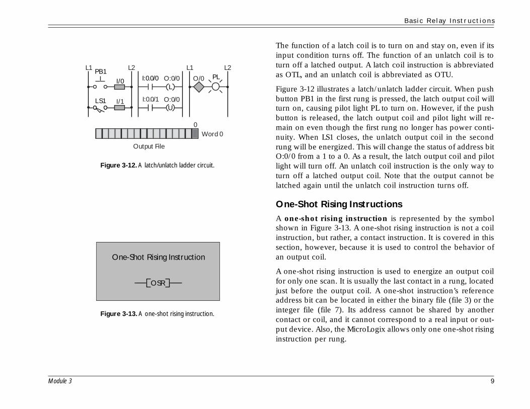
The function of a latch coil is to turn on and stay on, even if itsinput condition turns off. The function of an unlatch coil is toturn off a latched output. A latch coil instruction is abbreviatedas OTL, and an unlatch coil is abbreviated as OTU.
Figure 3-12 illustrates a latch/unlatch ladder circuit. When pushbutton PB1 in the first rung is pressed, the latch output coil willturn on, causing pilot light PL to turn on. However, if the pushbutton is released, the latch output coil and pilot light will re-main on even though the first rung no longer has power conti-nuity. When LS1 closes, the unlatch output coil in the secondrung will be energized. This will change the status of address bitO:0/0 from a 1 to a 0. As a result, the latch output coil and pilotlight will turn off. An unlatch coil instruction is the only way toturn off a latched output coil. Note that the output cannot belatched again until the unlatch coil instruction turns off.
One-Shot Rising InstructionsA one-shot rising instruction is represented by the symbolshown in Figure 3-13. A one-shot rising instruction is not a coilinstruction, but rather, a contact instruction. It is covered in thissection, however, because it is used to control the behavior ofan output coil.
A one-shot rising instruction is used to energize an output coilfor only one scan. It is usually the last contact in a rung, locatedjust before the output coil. A one-shot instruction’s referenceaddress bit can be located in either the binary file (file 3) or theinteger file (file 7). Its address cannot be shared by anothercontact or coil, and it cannot correspond to a real input or out-put device. Also, the MicroLogix allows only one one-shot risinginstruction per rung.
Figure 3-13. A one-shot rising instruction.
Figure 3-12. A latch/unlatch ladder circuit.
One-Shot Rising Instruction
OSR
PLI: 0.0/0L
U
Output File
Word 0
PB1
LS1
L1 L2 L1 L2
I: 0.0/1 O: 0/0
O: 0/0 O/0I/0
I/1
0

B a s i c R e l a y I n s t r u c t i o n s
10 Module 3
When the logic before a one-shot rising instruction becomes en-ergized (see Figure 3-14), the one-shot rising instruction will beenergized. As a result, the output coil and output device will turnon. A one-shot rising instruction, however, will only stay ener-gized for one scan, even if its driving logic remains energized.Thus, after one scan, the one-shot rising instruction, the outputcoil, and the associated field output device will turn off, even ifthe rest of the rung still has continuity. A one-shot rising instruc-tion is very useful for resetting output signals in one scan—forexample, for unlatching an output in one scan so that it will beready to latch again in the next scan.
Figure 3-14.(a) Ladder diagrams showing a one-shot rising instruction, which willbe energized for only one scan even if its input logic remains energized.(b) The timing diagram for a one-shot rising instruction.
LS I: 0.0/3 B3: 1/7
Scan 1
Scan 2
SOLOSR
O: 0/3I/3 O/3
L1 L2 L1 L2
LS I: 0.0/3 B3: 1/7 SOL
OSR
O: 0/3I/3 O/3
L1 L2 L1 L2
B3: 1/7
I: 0.0/3
O: 0/3
1 Scan
OSR
LS
(a)
(b)

B a s i c R e l a y I n s t r u c t i o n s
Module 3 11
3-4 Special Programming Issues
This section covers special issues you may encounter while pro-gramming a MicroLogix 1000 controller. At the end of this sec-tion you will know the techniques associated with three specialprogramming issues:
• ladder scan evaluation
• the programming of normally closed input devices
• safety device programming
Ladder Scan EvaluationThe way the controller evaluates the ladder program determinesthe order in which the programmed instructions will be executed.Thus, ladder scan evaluation can have a profound effect on theway the PLC and its associated machine or process operate.
A PLC’s scan consists of three activities (see Figure 3-15):
1. reading the inputs
2. executing the control program
3. updating the outputs
Once the PLC reads the status of the input devices, it begins toexecute the ladder control program. It starts its execution at thetop left corner of the ladder program and proceeds from left toright down the control program until it reaches the end of thelast ladder rung. The PLC evaluates the ladder program onceper scan. After the control program has been executed, the con-troller updates the status of the outputs according to the resultsof the control program.
Figure 3-15.The three parts of a PLC’s scan: reading the inputs, executing the controlprogram, and updating the outputs.
ExecuteControl Program
UpdateOutputs
ReadInputs
B a s i c R e l a y I n s t r u c t i o n s
12 Module 3
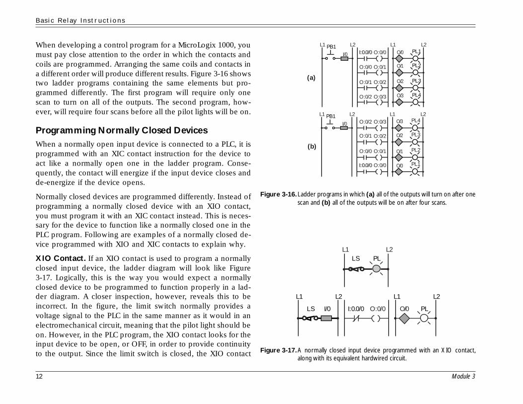
When developing a control program for a MicroLogix 1000, youmust pay close attention to the order in which the contacts andcoils are programmed. Arranging the same coils and contacts ina different order will produce different results. Figure 3-16 showstwo ladder programs containing the same elements but pro-grammed differently. The first program will require only onescan to turn on all of the outputs. The second program, how-ever, will require four scans before all the pilot lights will be on.
Programming Normally Closed DevicesWhen a normally open input device is connected to a PLC, it isprogrammed with an XIC contact instruction for the device toact like a normally open one in the ladder program. Conse-quently, the contact will energize if the input device closes andde-energize if the device opens.
Normally closed devices are programmed differently. Instead ofprogramming a normally closed device with an XIO contact,you must program it with an XIC contact instead. This is neces-sary for the device to function like a normally closed one in thePLC program. Following are examples of a normally closed de-vice programmed with XIO and XIC contacts to explain why.
XIO Contact. If an XIO contact is used to program a normallyclosed input device, the ladder diagram will look like Figure3-17. Logically, this is the way you would expect a normallyclosed device to be programmed to function properly in a lad-der diagram. A closer inspection, however, reveals this to beincorrect. In the figure, the limit switch normally provides avoltage signal to the PLC in the same manner as it would in anelectromechanical circuit, meaning that the pilot light should beon. However, in the PLC program, the XIO contact looks for theinput device to be open, or OFF, in order to provide continuityto the output. Since the limit switch is closed, the XIO contact Figure 3-17.A normally closed input device programmed with an XIO contact,
along with its equivalent hardwired circuit.
Figure 3-16.Ladder programs in which (a) all of the outputs will turn on after onescan and (b) all of the outputs will be on after four scans.
I: 0.0/0 O: 0/0
O: 0/0 O: 0/1
O: 0/1 O: 0/2
O: 0/2 O: 0/3
PL1
PL2
PL3
PL4PB1
O/0
O/1
O/2
O/3I/0
L1 L2 L1 L2
I: 0.0/0 PL1
PL2
PL3
PL4
PB1O: 0/0
O: 0/0 O: 0/1
O: 0/1 O: 0/2
O: 0/2 O: 0/3
O/0
O/1
O/2
O/3
I/0
L1
(a)
(b)
L2 L1 L2
PLI: 0.0/0
PLLSL1 L2
LS O: 0/0
L1 L2 L1 L2
I/0 O/0

B a s i c R e l a y I n s t r u c t i o n s
Module 3 13
will not be energized. Accordingly, the pilot light will be off.Under these conditions, the limit switch must open for the XIOcontact to be energized and the pilot light to turn on. This iscontrary to the way the circuit should work.
XIC Contact. Figure 3-18 shows the circuit from Figure 3-17programmed with an XIC contact. As in the previous laddercircuit, the normally closed limit switch provides a voltage tothe PLC. However, in this program, the XIC contact examinesthe limit switch for a closed condition in order to provide conti-nuity to the rung. Since the limit switch is closed, the contactwill be energized. In turn, the output coil and pilot light will beenergized. If the limit switch opens, the pilot light will turn off.Thus, the circuit works correctly.
Safety Device ProgrammingWhen connecting safety devices to PLCs, there is one cardinalrule to remember: never use a normally open device programmedwith an XIO contact instruction. The following explains why.
To implement the safety stop circuit shown in Figure 3-19, youmust use a normally closed input device programmed with anXIC instruction. In this configuration, when the start push but-ton is pressed, the motor will turn on because both of the XICcontacts will detect that their inputs are closed. When the startbutton is released, the motor will stay on because contact O:0/0seals the circuit. When the stop push button is pressed, the XICinstruction will detect that the stop button is open and turn off.This will turn off the motor circuit.
Moreover, if the motor in this circuit is sealed on and the con-nection from the stop push button breaks, the XIC instructionthat references the stop push button will detect an OFF, or open,condition. As a result, it will turn off the motor automatically.This creates a fail-safe circuit that is ideal for safety situations.
Figure 3-19.(a) A fail-safe safety stop circuit using a normally closed deviceprogrammed with an XIC instruction. (b) A safety stop circuit using anormally open device programmed with an XIO instruction. In thiscircuit, once the motor is on, the motor cannot be turned off if thesafety stop button malfunctions.
Figure 3-18.A normally closed input device programmed with an XIC contact,along with its equivalent hardwired circuit.
PLI: 0.0/0
PLLS
L1 L2
LS O: 0/0
L1 L2 L1 L2
I/0 O/0
I: 0.0/0 I: 0.0/1M
Start
Stop
O: 0/0
O: 0/0
O/0I/0
I/1
L1
(a)
(b)
L2 L1 L2
Motor
I: 0.0/0 I: 0.0/1M
Start
Stop
O: 0/0
O: 0/0
O/0I/0
I/1
L1 L2 L1 L2
Motor
B a s i c R e l a y I n s t r u c t i o n s
14 Module 3
3-5 Basic Relay Programming Examples
This section includes practical examples to help you apply whatyou have learned to two specific types of control circuits thatare often used in MicroLogix 1000 applications. At the end ofthis section, you will know about the I/O device wiring, ad-dressing, power wiring, and ladder programming of:
• simple motor control circuits
• forward/reverse motor circuits
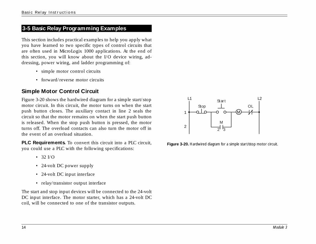
Simple Motor Control CircuitFigure 3-20 shows the hardwired diagram for a simple start/stopmotor circuit. In this circuit, the motor turns on when the startpush button closes. The auxiliary contact in line 2 seals thecircuit so that the motor remains on when the start push buttonis released. When the stop push button is pressed, the motorturns off. The overload contacts can also turn the motor off inthe event of an overload situation.
PLC Requirements. To convert this circuit into a PLC circuit,you could use a PLC with the following specifications:
• 32 I/O
• 24-volt DC power supply
• 24-volt DC input interface
• relay/transistor output interface
The start and stop input devices will be connected to the 24-voltDC input interface. The motor starter, which has a 24-volt DCcoil, will be connected to one of the transistor outputs.
Figure 3-20. Hardwired diagram for a simple star t/stop motor circuit.
M
M
StartOLStop
L1
1
2
L2
2 3

B a s i c R e l a y I n s t r u c t i o n s
Module 3 15
I/O Device and Power Wiring. The I/O devices to be wired tothe PLC are the stop push button, the start push button, and themotor starter. An internal instruction will be used to implementthe auxiliary contact in the PLC.
Figure 3-21 shows how the I/O devices and power will be wiredto the PLC. The stop button will be wired to the first inputterminal (I:0.0/0) and the start button to the next input terminal(I:0.0/1). These are both DC inputs. The motor starter’s coil willbe wired to the first transistor output terminal (O:0/2). The over-load contacts will remain wired in series with the motor starter’scoil, just as they were in the electromechanical circuit.
To apply power to the PLC, you should connect the MicroLogixto the DC power supply’s positive and negative voltages, notingthat the negative is connected to ground. The PLC itself shouldalso be grounded. Next, connect both the input devices and theoutput device to their respective DC power supply positive andnegative terminals.
Ladder Programming. Figure 3-22 shows the ladder controlprogram for the start/stop motor circuit. The ladder programuses the same logic that was used in the electromechanical cir-cuit; however, the PLC program uses XIC contacts to referencethe two inputs and an output coil to reference the motor. Inter-nal contact O:0/2, which references the output coil, seals thecircuit when the start push button is released.
The PLC program will work just like the hardwired circuit. Whenthe start button is pressed, the motor will turn on and stay on.When the stop button is pressed, the motor will turn off. If themotor is sealed on and the overload contact opens, the motorstarter will turn off. The reason for this is that the open overloadcontact will break the power continuity in the motor starter’scircuit. This situation is called low-voltage release.
Figure 3-22. Ladder program for the star t/stop motor circuit.
Figure 3-21.The I/O device and power wiring for the start/stop motor circuit. The+V supply connection shown occurs after the MCR power contact,which controls the power to the I/O devices.
M
Start
Stop I: 0.0/0 I: 0.0/1
L2L1L1 L2
O: 0/2
O: 0/2
OLO/2 MotorI/0
I/1
I/0 I/1 I/2 I/3 I/4 I/5 I/6 I/7 I/8 I/9 I/10 I/11I/12 I/13
OL
NOTUSED
NOTUSED
DCCOM
DCCOM
VACVDC
VACVDC
DC24+
DC24–O/0 O/1 O/2 O/3 O/4 O/5 O/6 O/7O/8 O/9O/10O/11
M
DC in+24v– NOT
USED
+V –VCom
–VCom +V
+V–V
Com
StartStop

B a s i c R e l a y I n s t r u c t i o n s
16 Module 3
Note that, since the motor’s PLC output coil is still on, the motorwill turn on again as soon as the overload contact recloses (i.e.,when the thermal overload heater cools off). Consequently, thiscircuit does not provide low-voltage protection. This can beundesirable and, in fact, dangerous in some applications. Forinstance, someone may be troubleshooting the motor to findout why it stopped. During this time, the overload contact maycool off and close again, causing the motor to start up againwithout warning.
Low-Voltage Protection. To provide low-voltage protection inthis circuit (see Figure 3-23), you must connect the auxiliarycontact from the motor starter as a real input to the PLC at inputterminal 2 (I:0.0/2). Then use an XIC contact to implement theauxiliary contact in the PLC. This replaces the internal contactused before. Now the motor is sealed after the start button ispushed because the auxiliary contact stays on as long as themotor starter’s coil is on. Therefore, this circuit still provideslow-voltage release, since the motor will turn off when the over-load opens. However, it also provides low-voltage protection,since the auxiliary contact will turn off when the motor starter’scoil turns off. This means that the motor will stay off even afterthe overload recloses. You must press the start button for themotor to turn on again.
Forward/Reverse Motor CircuitFigure 3-24 illustrates the hardwired electromechanical diagramfor a forward/reverse motor circuit (reversing motor starter). Thiscircuit has two normally open start push buttons—a forwardbutton and a reverse button. It also has two motor starter coils—one to start the motor going forward and another to start itgoing in reverse. The forward part of the circuit contains a con-tact labeled F1, which seals the forward push button. It alsocontains an R2 interlocking contact that prevents the forward
Figure 3-23.A star t/stop motor circuit with low-voltage release and low-voltageprotection.
Figure 3-24. Hardwired diagram for a forward/reverse motor circuit.
OLL2L1
F
R
Stop
R1
F1
R2
F2
REV
FWD
FWD
REV
M
M
Start
Stop I: 0.0/0 I: 0.0/1
L2L1L1 L2
O: 0/2 OLO/2 Motor
I: 0.0/2
I/2
I/0
I/1
B a s i c R e l a y I n s t r u c t i o n s
Module 3 17
motor starter from turning on if the reverse starter is already on.Moreover, it has a forward pilot light that turns on when themotor is moving in a forward direction.
The reverse part of the circuit contains similar elements andworks identically to the forward part. Additionally, the circuithas a normally closed stop push button that can turn off eitherthe forward or the reverse motor starter. It also contains an over-load contact that will turn off either starter in the event of anoverload condition.
PLC Requirements. To begin the implementation, you mustchoose the appropriate MicroLogix model for the application.In this example, the PLC will have the following specifications:
• 32 I/O
• 120-volt AC power supply
• 120-volt AC input interface
• relay/triac output interface
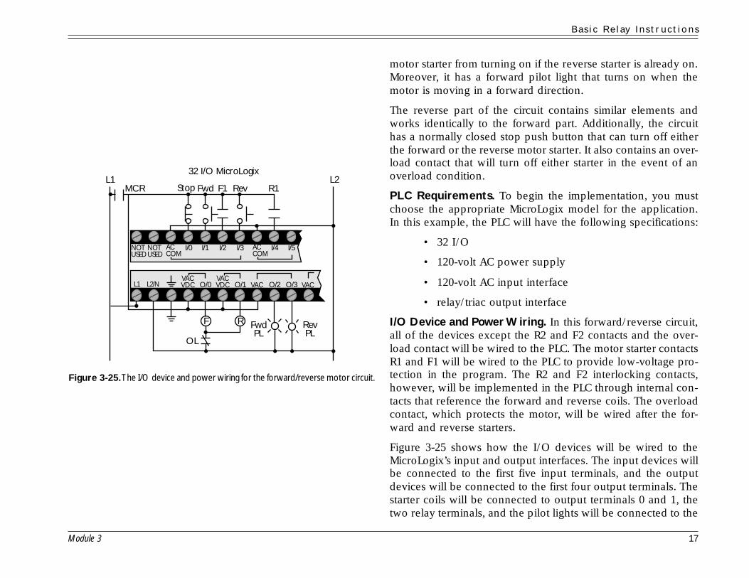
I/O Device and Power Wiring. In this forward/reverse circuit,all of the devices except the R2 and F2 contacts and the over-load contact will be wired to the PLC. The motor starter contactsR1 and F1 will be wired to the PLC to provide low-voltage pro-tection in the program. The R2 and F2 interlocking contacts,however, will be implemented in the PLC through internal con-tacts that reference the forward and reverse coils. The overloadcontact, which protects the motor, will be wired after the for-ward and reverse starters.
Figure 3-25 shows how the I/O devices will be wired to theMicroLogix’s input and output interfaces. The input devices willbe connected to the first five input terminals, and the outputdevices will be connected to the first four output terminals. Thestarter coils will be connected to output terminals 0 and 1, thetwo relay terminals, and the pilot lights will be connected to the
Figure 3-25.The I/O device and power wiring for the forward/reverse motor circuit.
I/0 I/1 I/2 I/3 I/4 I/5
OL
NOTUSED
NOTUSED
ACCOM
ACCOM
VACVDC
VACVDCO/0L1 L2/N O/1
RF
32 I/O MicroLogix
O/2 O/3VAC
FwdPL
RevPL
Stop FwdMCR F1 Rev R1L1 L2
VAC
B a s i c R e l a y I n s t r u c t i o n s
18 Module 3
first two triac output terminals, which are terminals 2 and 3. ThePLC will be connected to the L1 and L2 power lines. The inputand output devices will also be connected to the L1 and L2power lines.
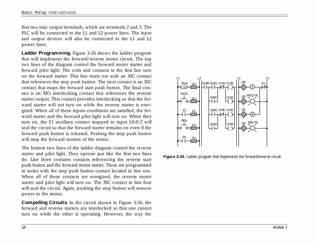
Ladder Programming. Figure 3-26 shows the ladder programthat will implement the forward/reverse motor circuit. The toptwo lines of the diagram control the forward motor starter andforward pilot light. The coils and contacts in the first line turnon the forward starter. This line starts out with an XIC contactthat references the stop push button. The next contact is an XICcontact that maps the forward start push button. The final con-tact is an XIO interlocking contact that references the reversestarter output. This contact provides interlocking so that the for-ward starter will not turn on while the reverse starter is ener-gized. When all of these inputs conditions are satisfied, the for-ward starter and the forward pilot light will turn on. When theyturn on, the F1 auxiliary contact mapped to input I:0.0/2 willseal the circuit so that the forward starter remains on even if theforward push button is released. Pushing the stop push buttonwill stop the forward motion of the motor.
The bottom two lines of the ladder diagram control the reversestarter and pilot light. They operate just like the first two linesdo. Line three contains contacts referencing the reverse startpush button and the forward motor starter. These are programmedin series with the stop push button contact located in line one.When all of these contacts are energized, the reverse motorstarter and pilot light will turn on. The XIC contact in line fourwill seal the circuit. Again, pushing the stop button will removepower to the motor.
Compelling Circuits. In the circuit shown in Figure 3-26, theforward and reverse starters are interlocked so that one cannotturn on while the other is operating. However, the way the
Figure 3-26. Ladder program that implements the forward/reverse circuit.
FOL
REV PL
Stop
REV
FWD
F1
R1
L1 L2L1L2
I: 0.0/0 I: 0.0/1
I: 0.0/2
I: 0.0/3
I: 0.0/4
O: 0/0
O: 0/0
O: 0/1
O: 0/2
O: 0/1
O: 0/3
I/2
O/0
O/3
I/1
I/3
I/4
R
O/1
FWD PLO/2
I/0
B a s i c R e l a y I n s t r u c t i o n s
Module 3 19
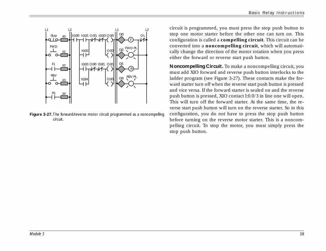
Figure 3-27.The forward/reverse motor circuit programmed as a noncompellingcircuit.
circuit is programmed, you must press the stop push button tostop one motor starter before the other one can turn on. Thisconfiguration is called a compelling circuit. This circuit can beconverted into a noncompelling circuit, which will automati-cally change the direction of the motor rotation when you presseither the forward or reverse start push button.
Noncompelling Circuit. To make a noncompelling circuit, youmust add XIO forward and reverse push button interlocks to theladder program (see Figure 3-27). These contacts make the for-ward starter turn off when the reverse start push button is pressedand vice versa. If the forward starter is sealed on and the reversepush button is pressed, XIO contact I:0.0/3 in line one will open.This will turn off the forward starter. At the same time, the re-verse start push button will turn on the reverse starter. So in thisconfiguration, you do not have to press the stop push buttonbefore turning on the reverse motor starter. This is a noncom-pelling circuit. To stop the motor, you must simply press thestop push button.
FOL
REV PL
Stop
REV
FWD
F1
R1
L1 L2L1L2
I: 0.0/0 I: 0.0/1
I: 0.0/2
I: 0.0/3
I: 0.0/4
O: 0/0
O: 0/0
O: 0/1 I:0.0/3
I: 0.0/1
O: 0/2
O: 0/1
O: 0/3
I/2
O/0
O/3
I/1
I/3
I/4
R
O/1
FWD PLO/2
I/0

B a s i c R e l a y I n s t r u c t i o n s
20 Module 3
3-6 Review
• A ladder diagram consists of many rungs formed by contacts and coils.
• The ladder rung matrix determines how many branches, contacts, and coils can be used to program a ladder rung.
• Power must flow through a ladder rung in a left-to-right direction.
• There are two types of contact instructions used to program inputs in a MicroLogix 1000: examine-if-closed (XIC) andexamine-if-open (XIO).
• An examine-if-closed contact provides power to the ladder rung when the contact’s reference device is closed, or ON.
• An examine-if-open contact provides power to the ladder rung when the contact’s reference device is open, or OFF.
• Four basic output instructions are used with the MicroLogix 1000: the standard output coil, the internal output coil, thelatch/unlatch coil, and the one-shot rising instruction.
• A standard output coil is used to energize a real field output device connected to the PLC.
• An internal output coil is used to implement interlocking in a ladder program.
• Latch/unlatch coils are used to turn an output on and keep it on, even if its input logic turns off.
• A one-shot rising instruction is used to turn an output on for one scan.
• In ladder scan evaluation, a PLC only evaluates the ladder program once during each scan, and it does so from left toright and from top to bottom.
• When programming a normally closed input device, you must use an examine-if-closed instruction for the device tobehave like a normally closed one in the PLC program.
• When programming a safety stop device in a PLC, never use a normally open device programmed with an examine-if-open contact.
• You should approach the programming of all PLC applications the same way: (1) identify the control requirements, (2)determine which I/O devices will be connected to the PLC, (3) determine which terminals the I/O devices will beconnected to, (4) determine how the I/O devices and PLC will be powered, and (5) develop a ladder program thatimplements the required control.

B a s i c R e l a y I n s t r u c t i o n s
Module 3 21
3-7 Job Aids
Job Aid 3-1: Programming Around Reverse Power FlowThe following ladder diagram allows power to flow from right to left through contact D. This type of reverse power flow is notpermitted in a MicroLogix ladder program.
If the reverse condition is not a required part of the output’s logic, then the ladder rung can be reprogrammed as follows to avoidthe reverse power flow condition:
If the reverse condition is a required part of the output’s logic, then the ladder rung can be reprogrammed as follows to avoid thereverse power flow condition:
Y
D
F
E
A B C
Y
D
F E
E
A B C
Y
D
F E
B C
A B C
A D E
