regard relay module and display card ifu, issue 2 · 4 regard relay module & relay display card...
TRANSCRIPT

RELAY MODULERELAY DISPLAY CARD
REGARDGAS DETECTION SYSTEM
RELAY DISPLAY
Alarm
Tripped
Power
Inhibit
RSHIFT
012:ALRM
INSTRUCTIONS FOR USE


REGARD Relay Module & Relay Display Card 3
CONTENTSPage
FOR YOUR SAFETY 4Safe operation 4
OPERATION 5Intended use 5Description 5
Operational fault relay 5Electromagnetic compatibility 5Display card front panel controls and indicators 6
Display 6LEDs 6Controls 7
Relay module indicators 7Acknowledging alarms 7
Relays configured “Single” and “LNAK” 8Operational faults 8
Operational fault codes 9Loss of communication between relay display card and relay module(s) 9
INSTALLATION 10Install relay display card 10Install relay modules 10
Set module numbers 13Connect equipment to relay terminals 14Connect DC supply to modules 14
Optional connections 15Remote reset 15Operational fault relay 15
Switch-on and initial checks 16
CONFIGURATION 17Command mode 17
Function of front panel controls in command mode 17Table of commands 17
Configure channel cards and master card 19Configure relay display card 19
Configuration sequence 20Optional configuration settings 25
MAINTENANCE 26Recommended maintenance intervals 26Commands for system maintenance 26
TECHNICAL DATA 30Relay display card 30Relay module 30Part numbers 31
REGARD Relay Module & Relay Display Card4
FOR YOUR SAFETYFollow the instructions
Follow the instructions for installation, operation and maintenance.
Use in areas subject to explosion hazards
The relay module and relay display card are not designed for use in a flammable atmospherewithout suitable protection.
Liability for proper function or damage
Liability for proper function of this apparatus is irrevocably transferred to the owner oroperator to the extent that the apparatus has been commissioned, serviced or repaired bypersonnel not employed or authorised by Draeger Service, or when this apparatus was usedin a manner not conforming to its intended use.
Draeger Limited can not be held responsible for any damage caused by non-compliance withthe above recommendations. The warranty and liability provisions of the terms and conditionsof sale and delivery of Draeger Limited are likewise not modified by recommendations givenabove.
Maintenance
This apparatus must be inspected and serviced by experts at regular intervals and a recordmaintained of such inspections and servicing. Repairs and general overhaul of this apparatusshould only be carried out by competent personnel.
We recommend that either a training course or service contract is obtained from the DraegerService department and that all repairs are also carried out by them.
Safe operationFor safe operation:
• Set relays on relay modules normally energised. In the event of power loss,communications failure or configuration data loss, the relays will de-energise.
• Connect an alarm device or other indicator to the operational fault relay on the relaydisplay card.

REGARD Relay Module & Relay Display Card 5
OPERATIONIntended use
The REGARD relay modules and relay display card provide:
• Additional common and voted alarm relays for a system comprising any combination ofchannel cards.
• A1, A2, A3 and Fault alarm relays for each channel of a Regard HART card or 8-channeldisplay card.
• Additional alarm relays for single-channel Regard cards.
The relay modules and relay display card are intended for permanent installation in a non-hazardous environment, such as a control room or marshalling cabinet.
DescriptionThe relay display card fits into the Regard rack and controls up to 16 relay modules. Eachrelay module has 16 relays. The relay modules are connected to the relay display card by asingle twisted-pair cable. Relay modules can be located up to 1km from the relay displaycard, allowing shorter cable runs between the actuating relays and the controlled devices.
Up to eight relay display cards can be fitted in a Regard system – i.e. connected to the sameRS-485 bus. This restriction is removed if remote configuration of the relay display cards isnot required.
The relay display card “listens” to the messages on the RS-485 bus between the Regardmaster card and channel cards. The relay display card requires a Regard master card foroperation. The master card must be configured to communicate with all channel cardsthat are programmed on the relay display card .
Operational fault relayThe relay display card has one relay, that indicates a critical operational fault of the relaydisplay card or relay module(s). This relay is always normally energised, latching and non-acknowledgeable.
Electromagnetic compatibilityThe Regard relay module and relay display card have been tested for compliance with theEMC Directive. Take the following steps to ensure compliance:
• Fully follow the installation instructions• Observe instructions to use screened cable, where given
Instructions or precautions which are essential for electromagnetic compatibility are identifiedby “EMC!” in the margin.

REGARD Relay Module & Relay Display Card6
Display card front panel controls and indicatorsDisplay
Display normally shows the state of each alarm relay in sequence. When a relay is in itsalarm state, only relays in alarm are displayed.
Display Meaning
001:CLR Relay 001 in non-alarm state
002:ALRM Relay 002 in alarm state
016:NOP Operation of relay 016 not set (no operation)
256:DBLD Relay 256 disabled
FAULT…FLTM…
Operational fault
Relays are numbered from 001 to 256. Relays on relay module 1 are numbers 001 to 016,relays on relay module 2 are numbers 017 to 032, and so on.
LEDs
LED State Meaning
AlarmOn
Off
Relay in alarm state
Relay not in alarm state
Tripped
On
Flashing
Off
Alarm tripped & acknowledged
Alarm tripped, not acknowledged
No alarm
PowerOn
Flashing
DC power on
Operational fault
Inhibit
On
Blinking on (normallyoff, on every 5 secs)
Blinking off (normallyon, off every 5 secs.)
Relays inhibited
Relay(s) disabled
Relays inhibited + relays disabled

REGARD Relay Module & Relay Display Card 7
ControlsFunction of front panel controls during normal operation:
Push button Result Note
Display relay latch mode E.g. 001:LACK
Display relay energise mode E.g. 023:ENER
SHIFT + Display relay operating mode E.g. 002:SA1
SHIFT + Channel number of relayconfigured SINGLE
E.g. 002:CH13
Display status of next relay —
Display status of previous relay —
+ Hold / release display of relaystatus
Key presses alternately hold andrelease display
R Acknowledge / reset alarm —
Relay module indicators• Power LED indicates that DC supply to module is connected.
• Relay LED next to each relay is lit when relay coil is energised.
Acknowledging alarmsThe action required to acknowledge an alarm depends on it mode.Momentarily connecting the remote reset terminals of the relay display card will alsoacknowledge an alarm.
Mode Action required to acknowledge alarm:
Common Press Reset on relay display card or master card
Single Automatically acknowledged by channel alarm (except when setLNAK)
Voted Press Reset on relay display card or master card
Alarm is acknowledged while alarm condition is still present
Setting Alarm trips Reset pressed Alarm clears Reset pressed
DNAK Relay trips Alarm acknowledgedRelay stays tripped
Relay clears No effect
LNAK Relay trips Alarm acknowledgedRelay stays tripped
No effect Relay clears
NAK Relay trips Alarm acknowledgedRelay stays tripped
Relay clears No effect
LACK Relay trips Alarm acknowledgedRelay clears
No effect No effect
ACK Relay trips Alarm acknowledgedRelay clears
No effect No effect

REGARD Relay Module & Relay Display Card8
Alarm is not acknowledged
Setting Alarm trips Alarm clears Reset pressed
DNAK Relay trips No effect Alarm acknowledged; relay clears
LNAK Relay trips No effect Alarm acknowledged; relay clears
NAK Relay trips Relay clears Alarm acknowledged; relay stayscleared
LACK Relay trips No effect Alarm acknowledged; relay clears
ACK Relay trips Relay clears Alarm acknowledged; relay stayscleared
Relays configured “Single” and “LNAK”Relays configured Single and LNAK must be acknowledged at the relay display card ormaster card, by pressing Reset or through remote reset input, if the channel card gas alarm isacknowledged at the channel card before the gas alarm clears.
Event Relay (alarm) state
Gas alarm trips on channel card Relay in alarm state.Tripped LED flashes
Channel card acknowledged Relay in alarm state.Tripped LED on
Gas level falls below trip point Relay in alarm stateTripped LED Off
Channel card acknowledged No change
Subsequent channel card acknowledgement No change
Reset pressed on relay display card or master card Relay in non alarm state.Tripped LED off
Operational faultsAn operation fault is a failure in the operation of either the relay display card or the relaymodule. Operational faults are either:• critical – card may stop working, or• advisory – card will continue to work safely, but its functions may be limited
When an operational fault occurs:• Power LED flashes once a second• If fault is critical, operational fault relay de-energises• Display shows fault code alternately with normal display
Press Reset to clear the fault. If fault will not clear, or recurs, call Draeger Service.

REGARD Relay Module & Relay Display Card 9
Operational fault codes
Fault code Meaning Remedy
FAULT BRFAULT BñFAULT BòFAULT BïFAULT Bð
Push button key fault. Advisory.One of the front panel push button keys appearsto be continuously pressed.
Check push button keys.
FAULT C Communications failure – Regard. Critical.Relay display card is not receiving data fromRegard channel cards. Alarms will not activaterelays.
Check RS-485 connectionto relay display card.Check master card andchannel card settings.
FAULT CM Communications failure – module. Critical.One or more relay modules are notacknowledging messages from the display card.(Modules may be receiving data, but this cannotbe confirmed.) Relays may not operate.
Check module number.Check RS-485 connectionto relay modules.
FAULT DRFAULT DC
Relay or Card Data error. Critical.Configuration settings have been corrupted.Default configuration settings will be used.Relays may not operate.
Check configurationsettings.
FAULT HV Supply voltage too high. Critical. Reduce supply voltage.
FAULT LV Supply voltage too low. Critical. Increase supply voltage.
FAULT Mx Microcontroller failure. Critical.Card/module has stopped working.
Hold down Reset to resetthe card.
FLTMC nn Module Communications failure. AdvisoryModule number nn is not receiving data fromthe relay display card. All relays on modulewill automatically de-energise.
Check module Nos. CheckRS-485 connection to relaymodules.
FLTMB nn Relay module DC supply brownout. AdvisoryFault in DC supply to relay module number nn.
Check power supply torelay module.
FLTMW nn Relay module watchdog reset. AdvisoryAn unknown error has caused relay modulenumber nn to reset.
Check relay moduleinstallation.
FAULT RR Remote reset fault. Advisory.Remote reset terminals appear to becontinuously shorted. The remote reset input willbe ignored.
Check remote reset.
FAULT WiFAULT We
Watchdog reset. Advisory.Unknown error caused card to reset. Card willcontinue to operate normally.
Check relay display cardinstallation.
Loss of communication between relay display card and relay module(s)If the RS-485 connection between the relay display card and a relay module is broken,or the communications between the two is otherwise interrupted, all relays on the relaymodule will de-energise.
• There is a delay of 5 seconds, after the connection is broken, before the relays de-energise. If the connection is re-made within 5 seconds, the relays do not de-energise.
• When the connection is re-made, the relays will stay de-energised for 10 seconds.

REGARD Relay Module & Relay Display Card10
INSTALLATIONHandle circuit boards with care during installation. Do not touch the circuit boards orcomponents.
Use of the relay modules and relay display card requires a Regard master card. All Regardchannel cards (e.g. 4-20, Ex, HART, 8-channel) must be connected to the same RS-485 busas the relay display card and the master card.
The diagram below shows how the relay display card and relay modules connect to a Regardsystem. Note that there is a separate RS-485 bus from the relay display card to the relaymodules. (Diagram for illustration only.)
RELAYDISPLAY
CARD
RE
LAY
MO
DU
LE
RE
LAY
MO
DU
LE
RE
LAY
MO
DU
LE
MASTERCARD
CHANNEL 1
CHANNEL 2
CHANNEL 99
MA
IN R
S-4
85 B
US
RS-485 BUS TO RELAY MODULES
Install relay display cardFit the relay display card in slot in Regard rack.
EMC! Tighten the screws on the front panel fully.
Install relay modules
EMC! Install the relay module in a metal enclosure or other enclosure which gives protection againstradio-frequency interference.
• Fit relay modules to 35mm symmetric or 32mm asymmetric DIN rail.
• Maximum cable length of the RS-485 bus must not exceed 1000m
• Voltage difference between 0V at the relay display card and all relay module must notexceed 5V. Use an RS-485 isolator if the voltage difference is greater that 5V.
REGARD Relay Module & Relay Display Card 11
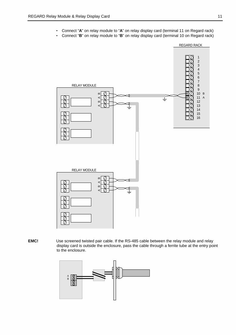
• Connect “A” on relay module to “A” on relay display card (terminal 11 on Regard rack)• Connect “B” on relay module to “B” on relay display card (terminal 10 on Regard rack)
123
54
6789
10111213141516
BA
REGARD RACK
BA
BA
BA
BA
RELAY MODULE
RELAY MODULE
EMC! Use screened twisted pair cable. If the RS-485 cable between the relay module and relaydisplay card is outside the enclosure, pass the cable through a ferrite tube at the entry pointto the enclosure.
AB
REGARD Relay Module & Relay Display Card12
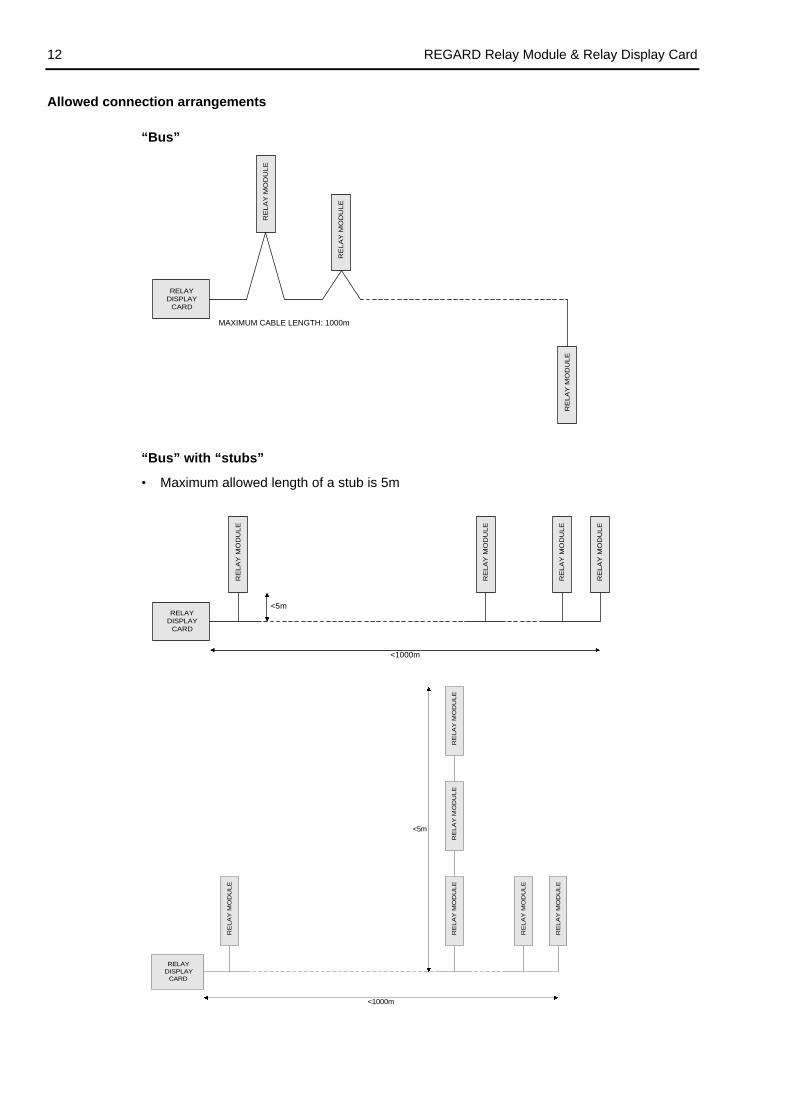
Allowed connection arrangements
“Bus”
RELAYDISPLAY
CARD
RE
LA
Y M
OD
ULE
RE
LA
Y M
OD
ULE
MAXIMUM CABLE LENGTH: 1000m
RE
LA
Y M
OD
ULE
“Bus” with “stubs”
• Maximum allowed length of a stub is 5m
<1000m
RELAYDISPLAY
CARD
RE
LA
Y M
OD
ULE
RE
LA
Y M
OD
ULE
RE
LA
Y M
OD
ULE
RE
LA
Y M
OD
ULE
<5m
<5m
<1000m
RELAYDISPLAY
CARD
RE
LA
Y M
OD
UL
E
RE
LA
Y M
OD
UL
E
RE
LA
Y M
OD
UL
E
RE
LA
Y M
OD
UL
ER
EL
AY
MO
DU
LE
RE
LA
Y M
OD
UL
E

REGARD Relay Module & Relay Display Card 13
Disallowed connection arrangements
“Star” – NOT ALLOWED
RELAYDISPLAY
CARD
RELAY MODULERELAY MODULE
RELAY MODULE
RELAY MODULE
“Tree” – NOT ALLOWED
RELAYDISPLAY
CARD
RELAY MODULE
RE
LA
Y M
OD
ULE
RE
LA
Y M
OD
ULE
RELAY MODULE
RELAY MODULE
Set module numbersSet the ID number of each module using the rotary switch (SW1) on the module.
SW1
Each module connected to a relay display card must have a unique ID number.• First module must be 0• ID numbers must be contiguous– do not leave any gaps in the sequence.
Examples:• 3 relay modules, numbers 0, 1, 2.• 16 relay modules: numbers 0, 1, 2, 3, 4, 5, 6, 7, 8, 9, A, B, C, D, E, F.
• Relay modules are identified by the relay display card as “ID number + 1”, e.g. the modulewith ID number 0 will be module 1 on the relay display card.
• The order of the relay modules on the RS-485 bus does not affect the operation of therelay modules. Using a logical numbering sequence for the modules makes programmingthe relay display card easier.
REGARD Relay Module & Relay Display Card14
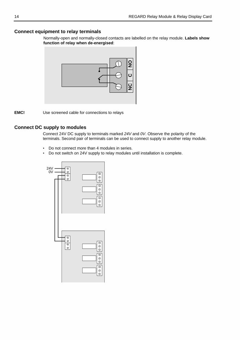
Connect equipment to relay terminalsNormally-open and normally-closed contacts are labelled on the relay module. Labels showfunction of relay when de-energised:
NC
NO
C
EMC! Use screened cable for connections to relays
Connect DC supply to modulesConnect 24V DC supply to terminals marked 24V and 0V. Observe the polarity of theterminals. Second pair of terminals can be used to connect supply to another relay module.
• Do not connect more than 4 modules in series.• Do not switch on 24V supply to relay modules until installation is complete.
24V0V
REGARD Relay Module & Relay Display Card 15
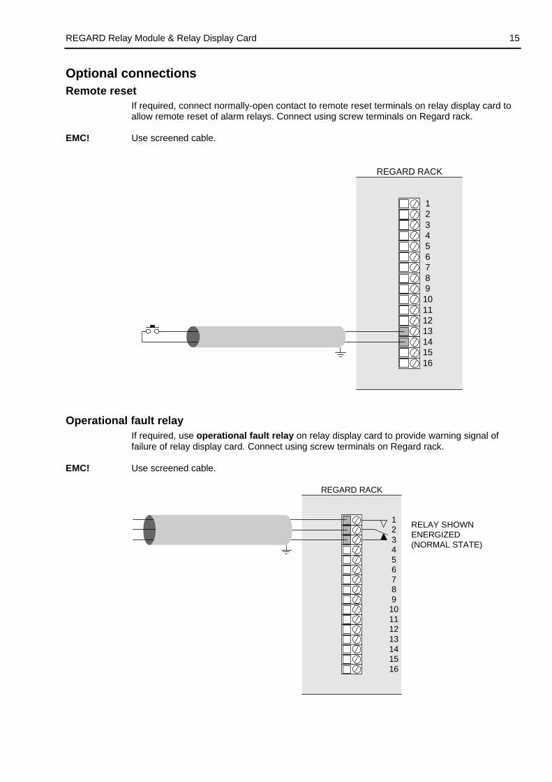
Optional connectionsRemote reset
If required, connect normally-open contact to remote reset terminals on relay display card toallow remote reset of alarm relays. Connect using screw terminals on Regard rack.
EMC! Use screened cable.
REGARD RACK
123
54
678910111213141516
Operational fault relayIf required, use operational fault relay on relay display card to provide warning signal offailure of relay display card. Connect using screw terminals on Regard rack.
EMC! Use screened cable.
REGARD RACK
123
54
6789
10111213141516
RELAY SHOWNENERGIZED(NORMAL STATE)

REGARD Relay Module & Relay Display Card16
Switch-on and initial checksSwitch on DC supply to the relay display card and the relay module(s).
Check that the Power LED on the relay display card and relay modules are lit.
If power to the relay modules is connected more than 5 seconds before the relay display card,the relay display card will indicate a communications fault warning. Press R push button tocancel the warning.
Relay display card may indicate a fault condition until it is correctly configured.
REGARD Relay Module & Relay Display Card 17
CONFIGURATIONCommand mode
Configuration and maintenance of the display card is performed using front panel controls anddisplay, by setting the card into command mode.
In command mode:
• Display of relays status is replaced by display of command mode options and configurationsettings;
• Operation of all relays on relay modules is prevented (“inhibited”). Inhibit LED on frontpanel of card is lit.
Configuration and maintenance commands are operated by selecting the command numberusing the and push buttons.
Entering command mode automatically inhibits all alarm relays on the module(s) connectedto the relay display card.
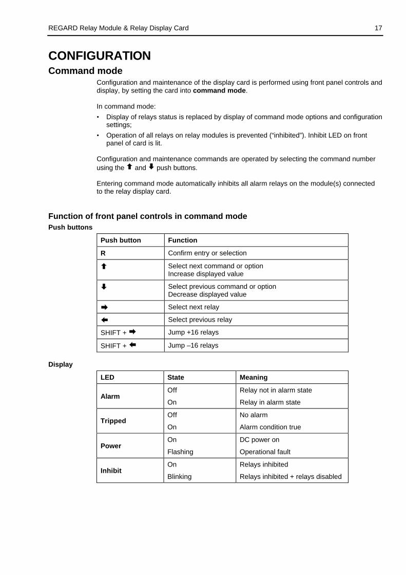
Function of front panel controls in command modePush buttons
Push button Function
R Confirm entry or selection
Select next command or optionIncrease displayed value
Select previous command or optionDecrease displayed value
Select next relay
Select previous relay
SHIFT + Jump +16 relays
SHIFT + Jump –16 relays
Display
LED State Meaning
AlarmOff
On
Relay not in alarm state
Relay in alarm state
TrippedOff
On
No alarm
Alarm condition true
PowerOn
Flashing
DC power on
Operational fault
InhibitOn
Blinking
Relays inhibited
Relays inhibited + relays disabled

REGARD Relay Module & Relay Display Card18
Table of commands
Cmd Command Function Command mode level DefaultNo. name Read Maint. Config. setting
00–0 CMD QUIT Quit command mode • • •
00–1 PASSWORD Enter password • • •
00–3 CHG P.WD Change password • •
04–4 RLY ENER Set relay normally energised orenergise on alarm
o • NORM†
11–1 VOTING Set relay voting configuration o •
11–4 RLY MODE Set relay mode: common, voted, singleor no operation
o • NOP†
11–7 LATCHINGSet relay latching, non-latching,delay-latching, acknowledgeable,non-acknowledgeable
o • LACK
14–0 LED TEST Test display & LEDs • • •
14–1 RMT TEST Test remote reset • • •
14–2 OPR TEST Test operational fault relay • •
14–4 RLY TEST Test relay operation • •
14–8 MOD TEST Test communications with modules • • •
52–0 MODULES Set number of relay modules o o • 1
52–1 CARD NUM Set relay display card number o o • 1
52–6 CHECKSUM Set communications checksum • CRC
60–1 DISPLAY Turn display on or off • ON
60–4 DISABLE Disable relay • • NO
• Command can be accessed and setting changedo Command can be accessed but setting cannot be changed
† Relays with mode NOP will always be de-energised.
There is no SAVE command on the relay display card (00-2). Settings are saved automatically.
The relay display card does not automatically exit command mode if no buttons are pressed for 10 minutes.There is no LOCK command (60-0) to lock the card in command mode.

REGARD Relay Module & Relay Display Card 19
Configure channel cards and master cardBefore configuring relay display card ensure that the other components of the Regard systemare correctly configured:
• Set operation of Regard master card and channel cards (4-20, Ex, HART, 8-channel, etc.)
• Regard Master card must be configured to communicate with all channel cards that willcontrol alarms on relay module(s).
Configure relay display cardUse the blank sheets at the end of this manual to plan and record the configuration of therelay modules.
Example
Card No. 1
Module No. 1
Relay No. Mode (11-4) Voting (11-1) Latching (11-7) Energise (04-4)
1 CA1 — ACK ENER
2 CA2 — ACK ENER
3 CA3 — ACK ENER
4 CF — LNAK NORM
5 SA1 CH1 — ACK ENER
6 SA2 CH1 — ACK ENER
7 SA3 CH1 — ACK ENER
8 SA1 CH2 — ACK ENER
9 SA2 CH2 — ACK ENER
10 SA3 CH2 — ACK ENER
11 SA1 CH3 — ACK ENER
12 SA2 CH3 — ACK ENER
13 SA3 CH3 — ACK ENER
14 SF CH1 — LNAK NORM
15 SF CH2 — LNAK NORM
16 SF CH3 — LNAK NORM
Card No. 1
Module No. 2
Relay No. Mode (11-4) Voting (11-1) Latching (11-7) Energise (04-4)
17 VA1 01 02 03 LACK ENER
18 VA2 01 02 03 LACK ENER
19 VA3 01 02 03 LACK ENER...
.
.
.
.
.
.
.
.
.
.
.
.

REGARD Relay Module & Relay Display Card20
Configuration sequenceEnter configuration-level password
Factory-set configuration password is CCCC.
00–1 PASSWORD PRESS DISPLAY
• Select 00–1 00-1
• • Enter command R PASSWORD
then
Ready for password entry ????
• Select first letter of password C???
• Confirm first letter R CC??
• Enter 2nd 3rd and 4th letters of password R CCCC
• EnterAccess at configuration level confirmed
R CONFIG
then
Command ends 00-1
Set number of relay modules
Set the number of relay modules connected to the relay display card.
52-0 MODULES PRESS DISPLAY
• Select 52-0 52-0
• • Enter command R MODULES
then
Current setting: 1
• Select number of modules, e.g. 3 3
• • Exit command R 52-0
REGARD Relay Module & Relay Display Card 21
Set function of relays
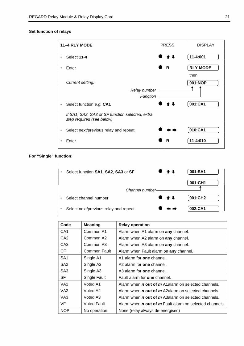
11–4 RLY MODE PRESS DISPLAY
• Select 11-4 11-4:001
• • Enter R RLY MODE
then
Current setting: 001:NOP
Relay number
Function
• Select function e.g. CA1 001:CA1
If SA1, SA2, SA3 or SF function selected, extrastep required (see below)
• Select next/previous relay and repeat 010:CA1
• • Enter R 11-4:010
For “Single” function:
• Select function SA1, SA2, SA3 or SF 001:SA1
001:CH1
Channel number
• Select channel number 001:CH2
• Select next/previous relay and repeat 002:CA1
Code Meaning Relay operation
CA1 Common A1 Alarm when A1 alarm on any channel.
CA2 Common A2 Alarm when A2 alarm on any channel.
CA3 Common A3 Alarm when A3 alarm on any channel.
CF Common Fault Alarm when Fault alarm on any channel.
SA1 Single A1 A1 alarm for one channel.
SA2 Single A2 A2 alarm for one channel.
SA3 Single A3 A3 alarm for one channel.
SF Single Fault Fault alarm for one channel.
VA1 Voted A1 Alarm when n out of m A1alarm on selected channels.
VA2 Voted A2 Alarm when n out of m A2alarm on selected channels.
VA3 Voted A3 Alarm when n out of m A3alarm on selected channels.
VF Voted Fault Alarm when n out of m Fault alarm on selected channels.
NOP No operation None (relay always de-energised)

REGARD Relay Module & Relay Display Card22
Set voting configuration
For relays configured voting (i.e. VA1, VA2, VA3 or VF), use command 11–1 to set votinginformation for each relay.
Example 2 out of 3 voting for channels 4, 6 and 9.
11-1 VOTING PRESS DISPLAY
• Select 11-1 11-1:001
• • Enter R VOTING
then
Current setting: n OF 1
Number of channels in voting group (m)
• Select value of m (e.g. 3) n OF 3
• • Enter R 1 OF 3
No of alarms required to trip (n)
• Select value of n (e.g. 2) 2 OF 3
• Enter R 1 CH1
First channel in voting group
Channel number
• Select first channel in voting group (e.g. 4) 1 CH4
• Enter R 2 CH5
Second channel in voting group
Channel number
• Select second channel in voting group (e.g. 6) 2 CH6
• Enter R 3 CH7
• Select last channel in voting group 3 CH9
• • Exit command R 11-1:001

REGARD Relay Module & Relay Display Card 23
Set relay latch/acknowledge operation
Determines the operation of a relay when the alarm condition clears or when the relay alarmis acknowledged.
Mode Function
ACK Non Latching and Acknowledgeable
Relay returns to non-alarm state when the relay alarm condition hascleared or the relay alarm has been acknowledged.
NAK Non Latching and Non Acknowledgeable
Relay returns to its non-alarm state when the relay alarm conditionhas cleared. Acknowledging the relay alarm whilst the alarmcondition is still true will not reset the relay.
LACK Latching and Acknowledgeable
Relay returns to its non alarm state when the relay alarm isacknowledged. The relay will not automatically go back to its non-alarm state when the alarm condition stops.
LNAK Latching and Non Acknowledgeable
Returns to its non alarm state when the alarm condition stops andthen the alarm is acknowledged. Acknowledging the relay alarmwhilst the alarm condition is still true will not reset the relay. Therelay will not automatically go back to its non-alarm state when thealarm condition stops.
DNAK Delay Latching and Non-Acknowledgeable
Relay returns to its non alarm state when the alarm condition stopsand the alarm has been acknowledged. Acknowledging the relayalarm whilst the alarm condition is still true will not reset the relay.The relay will automatically go back to its non-alarm state when thealarm condition stops if the relay has already been acknowledged.
11-7 LATCHING PRESS DISPLAY
• Select 11-7 11-7:001
• • Enter R LATCHINGthen
Current setting: 001:LACK
• Select new setting (e.g. ACK) 001:ACK
• Select next/previous relay until setting for allrelays configured
002:DNAK
• • Exit command R 11-7:002

REGARD Relay Module & Relay Display Card24
Set relays energise on alarm or normally energised
04–4 RLY ENER PRESS DISPLAY
• Select 04-4 04-4:001
• • Enter R RLY ENER
then
Current setting: 001:NORM
• Select NORM or ENER, e.g. ENER* 001:ENER
• Select next/previous relay and repeat 005:ENER
• • Exit command R 04-4:005
* NORM = Normally energised ENER = Energise on alarm
Set communications checksum
The relay display card must use the same communications checksum for RS-485communications as the rest of the Regard system. Use CRC whenever possible.
52-6 CHECKSUM PRESS DISPLAY
• Select 52-6 52-6
• • Enter command R CHECKSUM
then
Current setting: CRC
• Select mode, e.g. CSUM CSUM
• • Exit command R 52-6
Quit command mode
00-0 QUIT PRESS DISPLAY
• Select 00–0 00-0
• • Enter R QUIT:NO
• Select YES QUIT:YES
• EnterCard exits command mode
R 001:CLR

REGARD Relay Module & Relay Display Card 25
Optional configuration settingsSet relay display card number
To allow remote configuration, each relay display card must be assigned a unique cardnumber.
Note: This setting allows differentiation of relay display cards on the same RS-485 bus byremote configuration software. It does not affect the operation of the relay display card orrelay modules in any way.
52-1 CARD NUM PRESS DISPLAY
• Select 52-1 52-1
• • Enter R CARD NUM
then
Current setting: CARD:1
• Select card number, e.g. 2 CARD:2
• • Exit command R 52-1
Turn display offTo save power, the display can be turned off. Display is then blank unless a relay is in alarmor a button is pressed.
60–1 DISPLAY PRESS DISPLAY
• • Select 60-1 60-1
• Enter R DISPLAY
then
Current setting: ON
• Select ON or OFF, e.g. OFF OFF
• Exit command R 60-1
REGARD Relay Module & Relay Display Card26
MAINTENANCERecommended maintenance intervals
Daily:• Visual check to determine readiness for operation
At regular intervals:• Check connections to relays and between modules and relay display card• Check operation of relays (command 14-4)
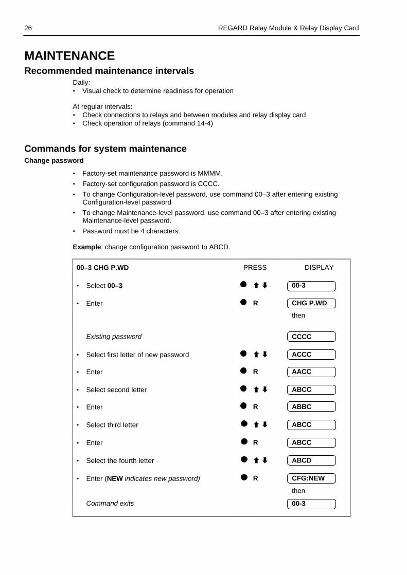
Commands for system maintenanceChange password
• Factory-set maintenance password is MMMM.
• Factory-set configuration password is CCCC.
• To change Configuration-level password, use command 00–3 after entering existingConfiguration-level password
• To change Maintenance-level password, use command 00–3 after entering existingMaintenance-level password.
• Password must be 4 characters.
Example: change configuration password to ABCD.
00–3 CHG P.WD PRESS DISPLAY
• Select 00–3 00-3
• Enter R CHG P.WD
then
Existing password CCCC
• Select first letter of new password ACCC
• Enter R AACC
• Select second letter ABCC
• Enter R ABBC
• Select third letter ABCC
• Enter R ABCC
• Select the fourth letter ABCD
• Enter (NEW indicates new password) R CFG:NEW
then
Command exits 00-3

REGARD Relay Module & Relay Display Card 27
Test LEDs and display
14-0 LED TEST PRESS DISPLAY
• Select 14-0 14-0
• Press R to test R LED TEST
LEDs and display flash
• Press R to stop R 14-0
Test remote reset
14–1 RMT TEST PRESS DISPLAY
• Select 14-1 14-1
• Enter R RMT TEST
then
Remote reset terminals closed-circuit CLOSED
or
Remote reset terminals open-circuit OPEN
or
Remote reset terminals closed-circuited for morethan 20 seconds
FAULTY
• Press R to stop R 14-1
Test operational fault relay
14–2 OPR TEST PRESS DISPLAY
• Select 14-2 14-2
• Enter R OPR TEST
then
Relay in non alarm state OFF
or
Relay in alarm state ON
• Change relay state OFF
• Exit command R 14-2
REGARD Relay Module & Relay Display Card28
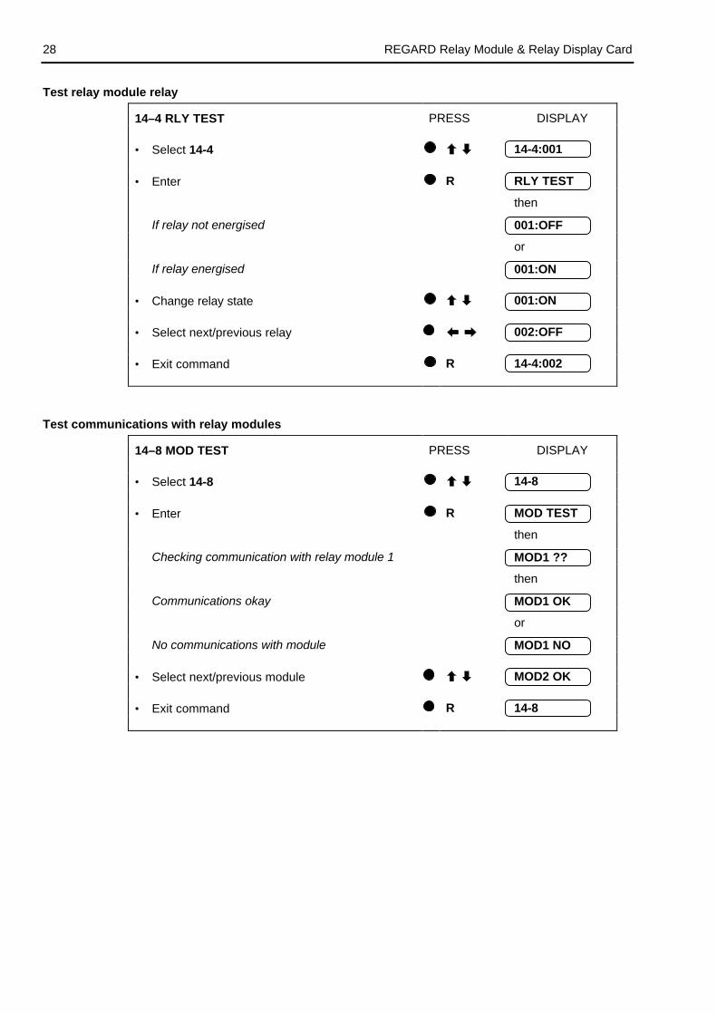
Test relay module relay
14–4 RLY TEST PRESS DISPLAY
• Select 14-4 14-4:001
• Enter R RLY TEST
then
If relay not energised 001:OFF
or
If relay energised 001:ON
• Change relay state 001:ON
• Select next/previous relay 002:OFF
• Exit command R 14-4:002
Test communications with relay modules
14–8 MOD TEST PRESS DISPLAY
• Select 14-8 14-8
• Enter R MOD TEST
then
Checking communication with relay module 1 MOD1 ??
then
Communications okay MOD1 OK
or
No communications with module MOD1 NO
• Select next/previous module MOD2 OK
• Exit command R 14-8
REGARD Relay Module & Relay Display Card 29
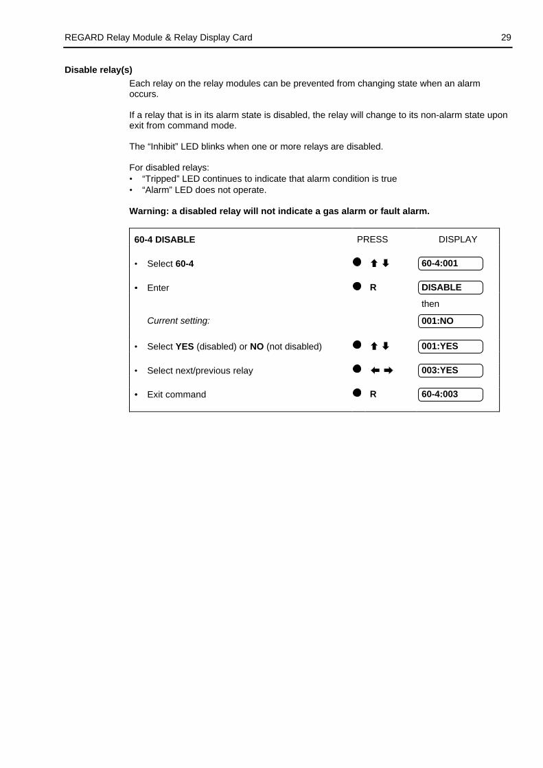
Disable relay(s)
Each relay on the relay modules can be prevented from changing state when an alarmoccurs.
If a relay that is in its alarm state is disabled, the relay will change to its non-alarm state uponexit from command mode.
The “Inhibit” LED blinks when one or more relays are disabled.
For disabled relays:• “Tripped” LED continues to indicate that alarm condition is true• “Alarm” LED does not operate.
Warning: a disabled relay will not indicate a gas alarm or fault alarm.
60-4 DISABLE PRESS DISPLAY
• Select 60-4 60-4:001
• • Enter R DISABLE
then
Current setting: 001:NO
• Select YES (disabled) or NO (not disabled) 001:YES
• Select next/previous relay 003:YES
• • Exit command R 60-4:003
REGARD Relay Module & Relay Display Card30
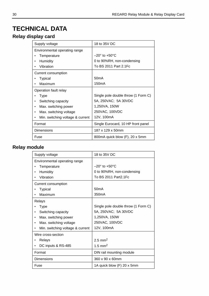
TECHNICAL DATARelay display card
Supply voltage 18 to 35V DC
Environmental operating range
• Temperature –20° to +50°C
• Humidity 0 to 90%RH, non-condensing
• Vibration To BS 2011 Part 2.1Fc
Current consumption
• Typical 50mA
• Maximum 150mA
Operation fault relay
• Type Single pole double throw (1 Form C)
• Switching capacity 5A, 250VAC; 5A 30VDC
• Max. switching power 1,250VA, 150W
• Max. switching voltage 250VAC, 100VDC
• Min. switching voltage & current 12V, 100mA
Format Single Eurocard, 10 HP front panel
Dimensions 187 x 129 x 50mm
Fuse 800mA quick blow (F), 20 x 5mm
Relay module
Supply voltage 18 to 35V DC
Environmental operating range
• Temperature –20° to +50°C
• Humidity 0 to 90%RH, non-condensing
• Vibration To BS 2011 Part2.1Fc
Current consumption
• Typical 50mA
• Maximum 350mA
Relays
• Type Single pole double throw (1 Form C)
• Switching capacity 5A, 250VAC; 5A 30VDC
• Max. switching power 1,250VA, 150W
• Max. switching voltage 250VAC, 100VDC
• Min. switching voltage & current 12V, 100mA
Wire cross-section
• Relays 2.5 mm2
• DC inputs & RS-485 1.5 mm2
Format DIN rail mounting module
Dimensions 360 x 90 x 60mm
Fuse 1A quick blow (F) 20 x 5mm

REGARD Relay Module & Relay Display Card 31
Part numbers
Description Part Number
Regard relay display card 4206081
Regard relay module (250VAC) 4206432
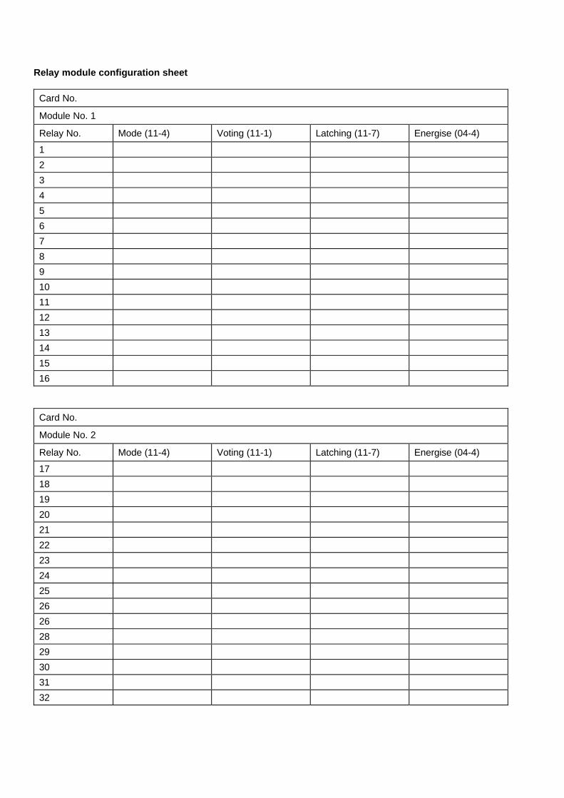
Relay module configuration sheet
Card No.
Module No. 1
Relay No. Mode (11-4) Voting (11-1) Latching (11-7) Energise (04-4)
1
2
3
4
5
6
7
8
9
10
11
12
13
14
15
16
Card No.
Module No. 2
Relay No. Mode (11-4) Voting (11-1) Latching (11-7) Energise (04-4)
17
18
19
20
21
22
23
24
25
26
26
28
29
30
31
32
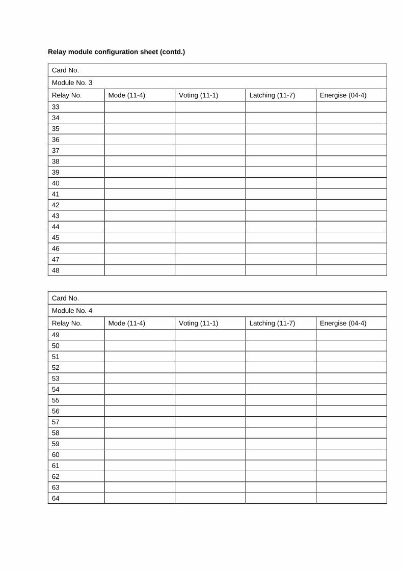
Relay module configuration sheet (contd.)
Card No.
Module No. 3
Relay No. Mode (11-4) Voting (11-1) Latching (11-7) Energise (04-4)
33
34
35
36
37
38
39
40
41
42
43
44
45
46
47
48
Card No.
Module No. 4
Relay No. Mode (11-4) Voting (11-1) Latching (11-7) Energise (04-4)
49
50
51
52
53
54
55
56
57
58
59
60
61
62
63
64

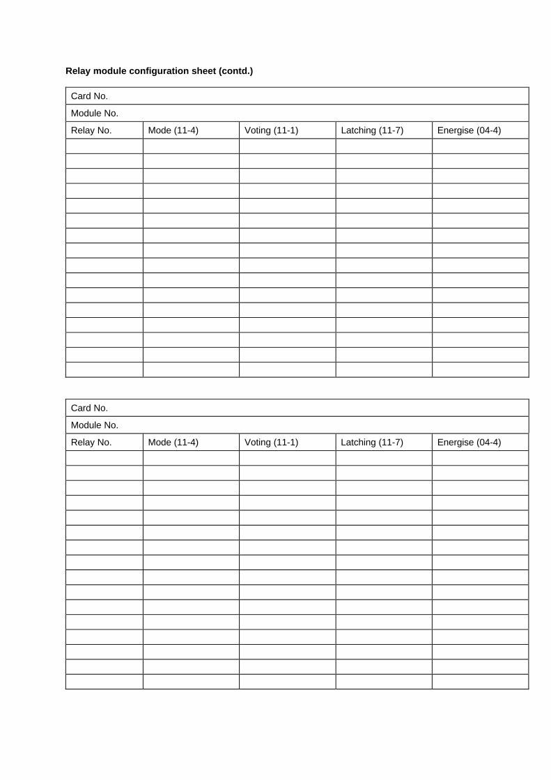
Relay module configuration sheet (contd.)
Card No.
Module No.
Relay No. Mode (11-4) Voting (11-1) Latching (11-7) Energise (04-4)
Card No.
Module No.
Relay No. Mode (11-4) Voting (11-1) Latching (11-7) Energise (04-4)
Relay module configuration sheet (contd.)
Card No.
Module No.
Relay No. Mode (11-4) Voting (11-1) Latching (11-7) Energise (04-4)
Card No.
Module No.
Relay No. Mode (11-4) Voting (11-1) Latching (11-7) Energise (04-4)

Draeger LtdKitty Brewster Industrial EstateBlythNorthumberlandNE24 4RGEngland
Tel. 01670 352891Fax 01670 356266
Dräger Sicherheitstechnik GmbHRevalstraße 1D-23560 LübeckGermany
Tel. 04 51 882 - 2794Fax 04 51 882 - 4991
Draeger Industrie S.A.3c, route de la FédérationF-67025 Strasbourg CedexFrance
Tel. 388 40 7676Fax 388 40 7667
Draeger Safety, Inc.P.O. Box 120Pittsburgh, PA 15 230U.S.A.
Tel. 412 787 8383Fax 412 787 2207
Draeger South East Asia Pte, Ltd.67, Ayer Rajah Crescent #06-03SGP-0513 SingaporeSingapore
Tel. 872 92 88Fax 773 20 33
http://www.draeger.com
Manual P/N 4206107Issue 2 - October 1998Subject to alteration
For use with relay display card software version 1.5