baseline model updating during bridge construction using
TRANSCRIPT

Baseline Model Updating During Bridge Construction Using Measured Strains
Masoud SanayeiBrian BrennerErin Santini-BellJesse SippleJohn PhelpsPaul Lefebvre
2010 Structures Congress14 May 2010Orlando, Florida

Presentation Outline
• Background
• Instrumentation
• Load Test
• Modeling
• Data Comparison
• Conclusions
2

National Science FoundationPartnership for Innovation
• Stimulate the transformation of knowledge created by the research and education enterprise into innovationsthat create new wealth; build strong local, regional and national economies, and improve the national well-being.
• Broaden the participation of all types of academic institutions and all citizens in activities to meet the diverse workforce needs of the national innovation enterprise.
• Catalyze or enhance enabling infrastructure that is necessary to foster and sustain innovation in the long-term.
3

New Bridge Design Paradigm
• Go beyond opening day design– Creation of baseline model– Integrate baseline modeling and model updating
through bridge service life
• Modify reactive mode of bridge management– Develop useful and cost-effective bridge
instrumentation plan– Deploy practical nondestructive tests– Have continuous feedback from bridge about current
health
4
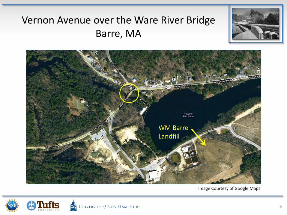
Vernon Avenue over the Ware River Bridge Barre, MA
5
Image Courtesy of Google Maps
WM Barre Landfill

Vernon Avenue over the Ware River Bridge Barre, MA
6
INSTRUMENTATION
2010 Structures Congress
Vernon Avenue Bridge Presentation
7

Instrumentation Plan
8

Instrumentation Plan
9

Instrumentation Plan
10

Instrumentation Summary
11
100 Strain Gauges36 Temperature Sensors36 Concrete Temperature16 Accelerometers12 Tiltmeters3 SWP4 Bi-Axial Tilt
Summary

Instrumentation by Geocomp
12

LOAD TEST
2010 Structures Congress
Vernon Avenue Bridge Presentation
13

Concrete Pour
14

Load Test
15

16
Load Test

17
Load Test

BRIDGE MODELING
2010 Structures Congress
Vernon Avenue Bridge Presentation
18

Bridge Modeling
19
Model Using SAP2000 Bridge Modeler (BrIM)
Model Using SAP2000 Solid and Shell Elements

Modeling Requirements
• Detailed finite element model that captures bridge performance– Exact geometry– Including bridge components such as diaphragms and
haunch
20

DATA COMPARISON
2010 Structures Congress
Vernon Avenue Bridge Presentation
21

Concrete Pour Data
22
Temperature not included in the SAP2000 frame model

Concrete Pour Data
23
Temperature included in the SAP2000 frame model

Objective Functions
24
Scalar Objective Function for Crawl Speed Test
Scalar Objective Function for Stop Location Test

Stop Location Load Test
25

Stop Location Load Test
26

Stop Location Load Test
27

Crawl Speed Load Test
28

Crawl Speed Load Test
29

CONCLUSION
2010 Structures Congress
Vernon Avenue Bridge Presentation
30

Conclusions
• Detailed 3D FEM of typical highway bridges is feasible to a high degree of accuracy
• Truck load testing performed on a newly constructed bridge can provide highly reliable strain data for calibrating baseline FEM’s.
• Calibrated FEM and load test strain data matched closely
• A calibrated FEM can be used as an effective tool for bridge management
31

Thank You for Listening
32
Acknowledgements
NSF-PFI Grant No. 0650258“Whatever Happened to Long Term BridgeDesign?”Program Director: Dr. Sara Nerlove
MassDOT – Bridge Construction
Town of Barre, MA – Bridge Management andOwner
E. T. & L. Corp. – Bridge Contractor
High Steel Structures, Inc. – Steel Fabricator
Atlantic Bridge and Engineering, Inc. – SteelErector
Fay, Spofford & Thorndike, Inc. – Bridge Design
Geocomp Corporation – Instrumentation
Bridge Diagnostics, Inc. – Bridge Testing