bands: a physical data structure to represent both ... · bands: a physical data structure to...
TRANSCRIPT
Bands: A Physical Data Structure to Represent Both Orientable andNon-Orientable 2-Manifold Meshes
Abstract
This paper presents a physical data structure to repre-sent both orientable and non-orientable 2-manifold meshes.With this data structure using simple examples, it is pos-sible to convincingly illustrate a variety of ideas in shapemodeling such as curvature and vertex defect; two-gonsand one-gons; polygons in elliptic and hyperbolic space;edge twists; half-edges and edge-ends; projective plane andKlein bottle.
1 Introduction and Motivation
The research and technology in graphics shape modelinghave heavily used concepts, terminologies, and techniquesin topology, which is a rather abstract mathematical topicand difficult to understand for students who are not math-ematically oriented (in fact, this is even the case for somemathematics students who are not specialized in topology).On the other hand, shape modeling is an important topicfor computer science students in particular for those work-ing on computer graphics. It has been one of the biggestchallenges in teaching shape modeling to explain difficulttopological concepts with tangible examples. In this paper,we presents a physical data structure to overcome this chal-lenge.
Formally, a (compact and closed 2-dimensional)mani-fold (also called atopological surface, or simply asurface)is a topological space in which every point has a neighbor-hood homeomorphic to an open disk. The surface isnon-orientableif it contains a Mobius band andorientableoth-erwise. Normally, the surface of any object in the real worldthat does not contain “infinitely thin connectors” makes anorientable topological surface.
A manifold meshM in graphics shape modeling is acollection of small and thin pieces that are properly gluedtogether along their boundaries to form a topological sur-faceS. This can be regarded as a graphM embedded ina topological surfaceS (i.e., the graphM is “drawn” onthe surfaceS). Concepts related to the manifold meshM
include vertices, edges, and faces. Vertices and edges ofthe meshM are simply the vertices and edges of the cor-responding graphM . If we cut the surfaceS along all theedges inM on the surfaceS, we get back the collection ofthe pieces that make the topological surfaceS. These piecesare calledfacesof the meshM . Most studies on manifoldmeshes assume that each of these pieces is homeomorphicto an open disk , i.e., each piece is a regular piece withoutholes and cut-points. The corresponding graph embeddingsatisfying this condition is said to be “cellular”. Followingthe convention in most research in computer graphics, inthis paper, we only study manifold meshes correspondingto cellular embeddings.
Let v be a vertex of the manifold meshM on the topo-logical surfaceS. By the definition of a topological surface,if we pick a small enough open disk aroundv on the surfaceS, we can see that all the edges incident onv are cyclicallyordered aroundv. Therefore, the meshM associates eachvertexv in M with a cyclic permutation of the edges inci-dent onv. Such a cyclic permutation of the incident edgesto a vertexv is called arotation at v. For a given graphG,if we fix a rotation for each vertex inG, we call the collec-tion of these rotations arotation systemof the graphG. Asdescribed above, each manifold meshM , as a graph embed-ded on a topological surface, gives a unique rotation systemfor the corresponding graph. What more important is thataccording to Heffter-Edmonds principle [6],every rotationsystem of a graph also uniquely describes an embedding ofthe graph on a topological surface.
Therefore, a manifold meshM on a topological surfacecan be uniquely represented by a rotation system ofM . Infact, this concept has been implicitly used in most shapemodelling data structures, such as Baumgart’s winged-edgestructure [5], Mantyla’s half-edge structure [8], and Guibasand Stolfi’s quad-edge structure [7]. A graphics shape mod-eler, TopMod[1], which is explicitly based on graph rota-tion systems, has been developed recently, and proved to bevery efficient and effective in handling shapes of compli-cated topological structures.
The concept of graph rotation systems provides a purecombinatorial characterization for manifold meshes on
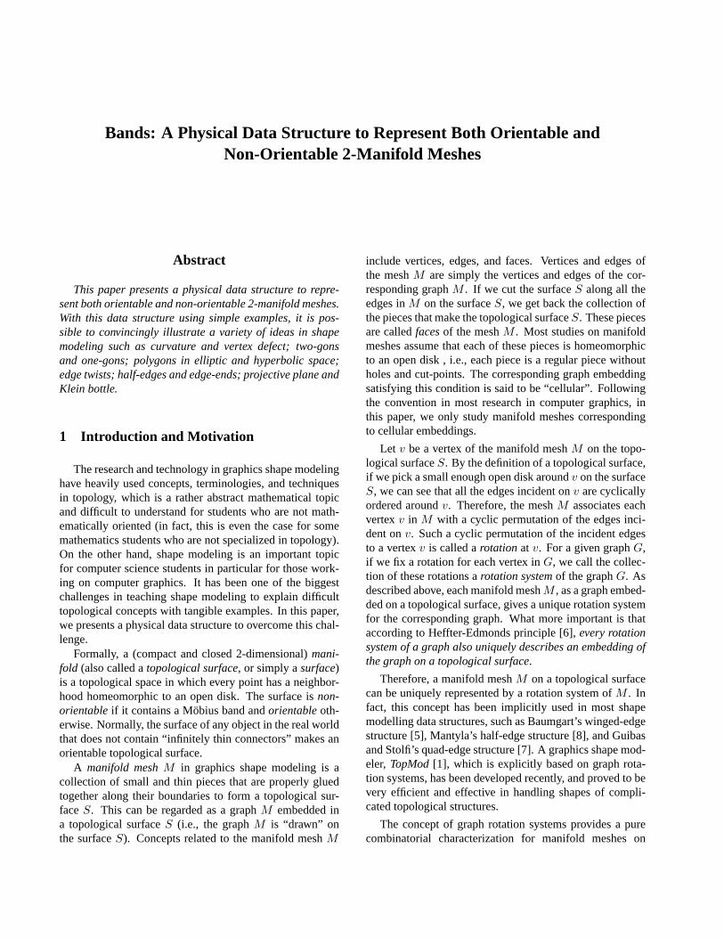
topological surfaces, which can be handled very efficientlyand effectively using computer techniques. On the otherhand, graph rotation systems still do not provide muchintuition for the corresponding topological surfaces, spe-cially when the surfaces are representing certain designatedshapes in the real world. This is particularly true for be-ginners in this area. For example, it is hardly to recognizethat the two graph rotation systems in Figure 1 correspondto two graphs embedded on the same surface that is a torus.
Figure 1. These two graph rotation systemscorrespond to two graphs embedded on thesame surface that is a torus.
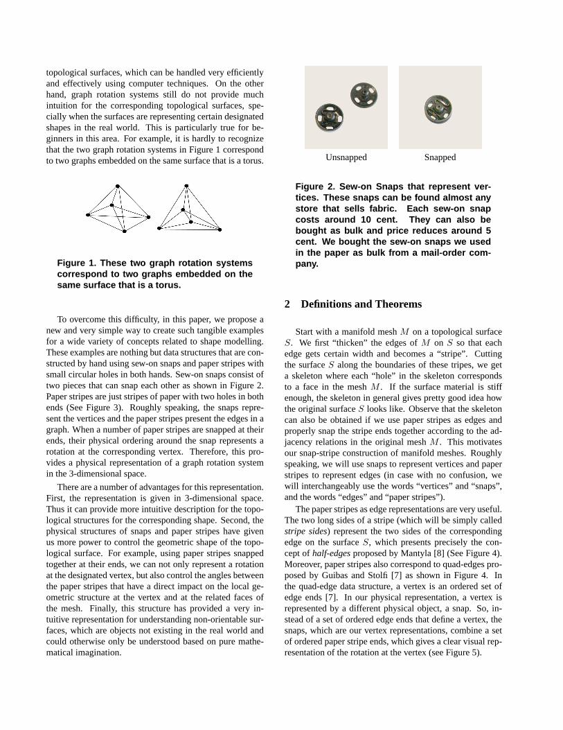
To overcome this difficulty, in this paper, we propose anew and very simple way to create such tangible examplesfor a wide variety of concepts related to shape modelling.These examples are nothing but data structures that are con-structed by hand using sew-on snaps and paper stripes withsmall circular holes in both hands. Sew-on snaps consist oftwo pieces that can snap each other as shown in Figure 2.Paper stripes are just stripes of paper with two holes in bothends (See Figure 3). Roughly speaking, the snaps repre-sent the vertices and the paper stripes present the edges in agraph. When a number of paper stripes are snapped at theirends, their physical ordering around the snap represents arotation at the corresponding vertex. Therefore, this pro-vides a physical representation of a graph rotation systemin the 3-dimensional space.
There are a number of advantages for this representation.First, the representation is given in 3-dimensional space.Thus it can provide more intuitive description for the topo-logical structures for the corresponding shape. Second, thephysical structures of snaps and paper stripes have givenus more power to control the geometric shape of the topo-logical surface. For example, using paper stripes snappedtogether at their ends, we can not only represent a rotationat the designated vertex, but also control the angles betweenthe paper stripes that have a direct impact on the local ge-ometric structure at the vertex and at the related faces ofthe mesh. Finally, this structure has provided a very in-tuitive representation for understanding non-orientable sur-faces, which are objects not existing in the real world andcould otherwise only be understood based on pure mathe-matical imagination.
Unsnapped Snapped
Figure 2. Sew-on Snaps that represent ver-tices. These snaps can be found almost anystore that sells fabric. Each sew-on snapcosts around 10 cent. They can also bebought as bulk and price reduces around 5cent. We bought the sew-on snaps we usedin the paper as bulk from a mail-order com-pany.
2 Definitions and Theorems
Start with a manifold meshM on a topological surfaceS. We first “thicken” the edges ofM on S so that eachedge gets certain width and becomes a “stripe”. Cuttingthe surfaceS along the boundaries of these tripes, we geta skeleton where each “hole” in the skeleton correspondsto a face in the meshM . If the surface material is stiffenough, the skeleton in general gives pretty good idea howthe original surfaceS looks like. Observe that the skeletoncan also be obtained if we use paper stripes as edges andproperly snap the stripe ends together according to the ad-jacency relations in the original meshM . This motivatesour snap-stripe construction of manifold meshes. Roughlyspeaking, we will use snaps to represent vertices and paperstripes to represent edges (in case with no confusion, wewill interchangeably use the words “vertices” and “snaps”,and the words “edges” and “paper stripes”).
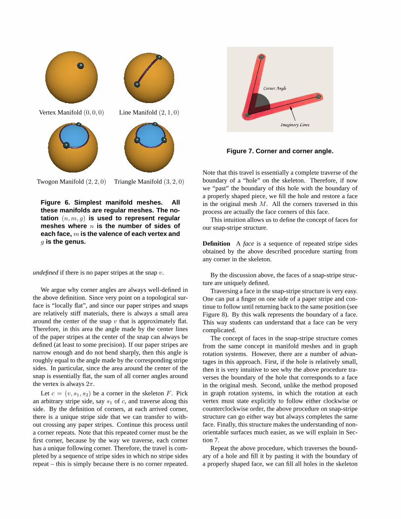
The paper stripes as edge representations are very useful.The two long sides of a stripe (which will be simply calledstripe sides) represent the two sides of the correspondingedge on the surfaceS, which presents precisely the con-cept ofhalf-edgesproposed by Mantyla [8] (See Figure 4).Moreover, paper stripes also correspond to quad-edges pro-posed by Guibas and Stolfi [7] as shown in Figure 4. Inthe quad-edge data structure, a vertex is an ordered set ofedge ends [7]. In our physical representation, a vertex isrepresented by a different physical object, a snap. So, in-stead of a set of ordered edge ends that define a vertex, thesnaps, which are our vertex representations, combine a setof ordered paper stripe ends, which gives a clear visual rep-resentation of the rotation at the vertex (see Figure 5).
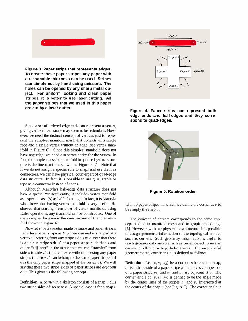
Figure 3. Paper stripe that represents edges.To create these paper stripes any paper witha reasonable thickness can be used. Stripescan simple cut by hand using scissors. Theholes can be opened by any sharp metal ob-ject. For uniform looking and clean paperstripes, it is better to use laser cutting. Allthe paper stripes that we used in this paperare cut by a laser cutter.
Since a set of ordered edge ends can represent a vertex,giving vertex role to snaps may seem to be redundant. How-ever, we need the distinct concept of vertices just to repre-sent the simplest manifold mesh that consists of a singleface and a single vertex without an edge (see vertex man-ifold in Figure 6). Since this simplest manifold does nothave any edge, we need a separate entity for the vertex. Infact, the simplest possible manifold in quad-edge data struc-ture is the line-manifold shown the Figure 6 [7]. Note thatif we do not assign a special role to snaps and use them asconnectors, we can have physical counterpart of quad-edgedata structure. In fact, it is possible to use glue, staple ortape as a connector instead of snaps.
Although Mantyla’s half-edge data structure does nothave a special “vertex” entity, it includes vertex manifoldas a special case [8] as half of an edge. In fact, it is Mantylawho shows that having vertex-manifold is very useful. Heshowed that starting from a set of vertex-manifolds usingEuler operations, any manifold can be constructed. One ofthe examples he gave is the construction of triangle mani-fold shown in Figure 6.
Now letF be a skeleton made by snaps and paper stripes.Let e be a paper stripe inF whose one end is snapped at avertexv. Starting from any stripe sides of e, note that thereis a unique stripe sides′ of a paper stripe such thats ands′ are “adjacent” in the sense that we can “transfer” fromsides to sides′ at the vertexv without crossing any paperstripes (the sides′ can belong to the same paper stripee ife is the only paper stripe snapped at the vertexv). We willsay that these two stripe sides of paper stripes areadjacentat v. This gives us the following concept.
Definition A corner in a skeleton consists of a snapv plustwo stripe sides adjacent atv. A special case is for a snapv
Figure 4. Paper strips can represent bothedge ends and half-edges and they corre-spond to quad-edges.
Figure 5. Rotation order.
with no paper stripes, in which we define the corner atv tobe simply the snapv.
The concept of corners corresponds to the same con-cept studied in manifold mesh and in graph embeddings[6]. However, with our physical data structure, it is possibleto assign geometric information to the topological entitiessuch as corners. Such geometry information is useful toteach geometrical concepts such as vertex defect, Gaussiancurvature, elliptic or hyperbolic spaces. The most usefulgeometric data, corner angle, is defined as follows.
Definition Let (v, s1, s2) be a corner, wherev is a snap,s1 is a stripe side of a paper stripep1, ands2 is a stripe sideof a paper stripep2, ands1 ands2 are adjacent atv. Thecorner angleof (v, s1, s2) is defined to be the angle madeby the center lines of the stripesp1 andp2 intersected atthe center of the snapv (see Figure 7). The corner angle is
Vertex Manifold(0, 0, 0) Line Manifold (2, 1, 0)
Twogon Manifold(2, 2, 0) Triangle Manifold(3, 2, 0)
Figure 6. Simplest manifold meshes. Allthese manifolds are regular meshes. The no-tation (n, m, g) is used to represent regularmeshes where n is the number of sides ofeach face, m is the valence of each vertex andg is the genus.
undefinedif there is no paper stripes at the snapv.
We argue why corner angles are always well-defined inthe above definition. Since very point on a topological sur-face is “locally flat”, and since our paper stripes and snapsare relatively stiff materials, there is always a small areaaround the center of the snapv that is approximately flat.Therefore, in this area the angle made by the center linesof the paper stripes at the center of the snap can always bedefined (at least to some precision). If our paper stripes arenarrow enough and do not bend sharply, then this angle isroughly equal to the angle made by the corresponding stripesides. In particular, since the area around the center of thesnap is essentially flat, the sum of all corner angles aroundthe vertex is always2π.
Let c = (v, s1, s2) be a corner in the skeletonF . Pickan arbitrary stripe side, says1 of c, and traverse along thisside. By the definition of corners, at each arrived corner,there is a unique stripe side that we can transfer to with-out crossing any paper stripes. Continue this process untila corner repeats. Note that this repeated corner must be thefirst corner, because by the way we traverse, each cornerhas a unique following corner. Therefore, the travel is com-pleted by a sequence of stripe sides in which no stripe sidesrepeat – this is simply because there is no corner repeated.
Figure 7. Corner and corner angle.
Note that this travel is essentially a complete traverse of theboundary of a “hole” on the skeleton. Therefore, if nowwe “past” the boundary of this hole with the boundary ofa properly shaped piece, we fill the hole and restore a facein the original meshM . All the corners traversed in thisprocess are actually the face corners of this face.
This intuition allows us to define the concept of faces forour snap-stripe structure.
Definition A face is a sequence of repeated stripe sidesobtained by the above described procedure starting fromany corner in the skeleton.
By the discussion above, the faces of a snap-stripe struc-ture are uniquely defined.
Traversing a face in the snap-stripe structure is very easy.One can put a finger on one side of a paper stripe and con-tinue to follow until returning back to the same position (seeFigure 8). By this walk represents the boundary of a face.This way students can understand that a face can be verycomplicated.
The concept of faces in the snap-stripe structure comesfrom the same concept in manifold meshes and in graphrotation systems. However, there are a number of advan-tages in this approach. First, if the hole is relatively small,then it is very intuitive to see why the above procedure tra-verses the boundary of the hole that corresponds to a facein the original mesh. Second, unlike the method proposedin graph rotation systems, in which the rotation at eachvertex must state explicitly to follow either clockwise orcounterclockwise order, the above procedure on snap-stripestructure can go either way but always completes the sameface. Finally, this structure makes the understanding of non-orientable surfaces much easier, as we will explain in Sec-tion 7.
Repeat the above procedure, which traverses the bound-ary of a hole and fill it by pasting it with the boundary ofa properly shaped face, we can fill all holes in the skeleton
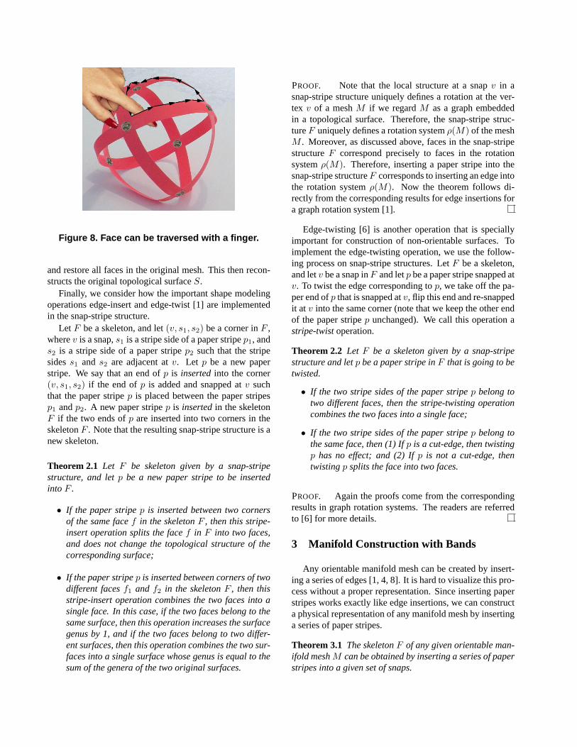
Figure 8. Face can be traversed with a finger.
and restore all faces in the original mesh. This then recon-structs the original topological surfaceS.
Finally, we consider how the important shape modelingoperations edge-insert and edge-twist [1] are implementedin the snap-stripe structure.
Let F be a skeleton, and let(v, s1, s2) be a corner inF ,wherev is a snap,s1 is a stripe side of a paper stripep1, ands2 is a stripe side of a paper stripep2 such that the stripesidess1 and s2 are adjacent atv. Let p be a new paperstripe. We say that an end ofp is insertedinto the corner(v, s1, s2) if the end ofp is added and snapped atv suchthat the paper stripep is placed between the paper stripesp1 andp2. A new paper stripep is insertedin the skeletonF if the two ends ofp are inserted into two corners in theskeletonF . Note that the resulting snap-stripe structure is anew skeleton.
Theorem 2.1 Let F be skeleton given by a snap-stripestructure, and letp be a new paper stripe to be insertedinto F .
• If the paper stripep is inserted between two cornersof the same facef in the skeletonF , then this stripe-insert operation splits the facef in F into two faces,and does not change the topological structure of thecorresponding surface;
• If the paper stripep is inserted between corners of twodifferent facesf1 and f2 in the skeletonF , then thisstripe-insert operation combines the two faces into asingle face. In this case, if the two faces belong to thesame surface, then this operation increases the surfacegenus by 1, and if the two faces belong to two differ-ent surfaces, then this operation combines the two sur-faces into a single surface whose genus is equal to thesum of the genera of the two original surfaces.
PROOF. Note that the local structure at a snapv in asnap-stripe structure uniquely defines a rotation at the ver-tex v of a meshM if we regardM as a graph embeddedin a topological surface. Therefore, the snap-stripe struc-tureF uniquely defines a rotation systemρ(M) of the meshM . Moreover, as discussed above, faces in the snap-stripestructureF correspond precisely to faces in the rotationsystemρ(M). Therefore, inserting a paper stripe into thesnap-stripe structureF corresponds to inserting an edge intothe rotation systemρ(M). Now the theorem follows di-rectly from the corresponding results for edge insertions fora graph rotation system [1].
Edge-twisting [6] is another operation that is speciallyimportant for construction of non-orientable surfaces. Toimplement the edge-twisting operation, we use the follow-ing process on snap-stripe structures. LetF be a skeleton,and letv be a snap inF and letp be a paper stripe snapped atv. To twist the edge corresponding top, we take off the pa-per end ofp that is snapped atv, flip this end and re-snappedit at v into the same corner (note that we keep the other endof the paper stripep unchanged). We call this operation astripe-twistoperation.
Theorem 2.2 Let F be a skeleton given by a snap-stripestructure and letp be a paper stripe inF that is going to betwisted.
• If the two stripe sides of the paper stripep belong totwo different faces, then the stripe-twisting operationcombines the two faces into a single face;
• If the two stripe sides of the paper stripep belong tothe same face, then (1) Ifp is a cut-edge, then twistingp has no effect; and (2) Ifp is not a cut-edge, thentwistingp splits the face into two faces.
PROOF. Again the proofs come from the correspondingresults in graph rotation systems. The readers are referredto [6] for more details.
3 Manifold Construction with Bands
Any orientable manifold mesh can be created by insert-ing a series of edges [1, 4, 8]. It is hard to visualize this pro-cess without a proper representation. Since inserting paperstripes works exactly like edge insertions, we can constructa physical representation of any manifold mesh by insertinga series of paper stripes.
Theorem 3.1 The skeletonF of any given orientable man-ifold meshM can be obtained by inserting a series of paperstripes into a given set of snaps.
PROOF. As explained earlier, a skeletonF correspondsuniquely to a graph rotation system, which precisely de-scribes a manifold mesh. Moreover, inserting paper stripesdescribes exactly the process of edge insertions, and snapsrepresent vertices in a graph rotation system. Therefore, itwill suffice to prove that every graph rotation system canbe obtained by inserting a series of edges into a given setof isolated vertices (which makes a collection of vertex-manifolds in the initial stage). Since the proofs of theseresults for graph rotation systems have been developed in[1, 4], the results based on snap-stripe structures as stated inthe current theorem follow.
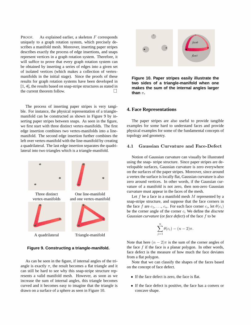
The process of inserting paper stripes is very tangi-ble. For instance, the physical representation of a triangle-manifold can be constructed as shown in Figure 9 by in-serting paper stripes between snaps. As seen in the figure,we first start with three distinct vertex-manifolds. The firstedge insertion combines two vertex-manifolds into a line-manifold. The second edge insertion further combines theleft over vertex-manifold with the line-manifold by creatinga quadrilateral. The last edge insertion separates the quadri-lateral into two triangles which is a triangle-manifold.
Three distinct One line-manifoldvertex-manifolds and one vertex-manifold
A quadrilateral Triangle-manifold
Figure 9. Constructing a triangle-manifold.
As can be seen in the figure, if internal angles of the tri-angle is exactlyπ, the result becomes a flat triangle and itcan still be hard to see why this snap-stripe structure rep-resents a valid manifold mesh. However, as soon as weincrease the sum of internal angles, this triangle becomescurved and it becomes easy to imagine that the triangle isdrawn on a surface of a sphere as seen in Figure 10.
Figure 10. Paper stripes easily illustrate thetwo sides of a triangle-manifold when onemakes the sum of the internal angles largerthan π.
4. Face Representations
The paper stripes are also useful to provide tangibleexamples for some hard to understand faces and providephysical examples for some of the fundamental concepts oftopology and geometry.
4.1 Gaussian Curvature and Face-Defect
Notion of Gaussian curvature can visually be illustratedusing the snap- stripe structure. Since paper stripes are de-velopable surfaces, Gaussian curvature is zero everywhereon the surfaces of the paper stripes. Moreover, since arounda vertex the surface is locally flat, Gaussian curvature is alsozero around vertices. In other words, if the Gaussian cur-vature of a manifold is not zero, then non-zero Gaussiancurvature must appear in the faces of the mesh.
Let f be a face in a manifold meshM represented by asnap-stripe structure, and suppose that the face corners inthe facef arec1, . . ., cn. For each face cornerci, let θ(ci)be the corner angle of the cornerci We define thediscreteGaussian curvature(or face defect) of the facef to be
n∑j=1
θ(ci)− (n− 2)π.
Note that here(n − 2)π is the sum of the corner angles ofthe facef if the face is a planar polygon. In other words,face defect is the measure of how much the face deviatesfrom a flat polygon.
Note that we can classify the shapes of the faces basedon the concept of face defect.
• If the face defect is zero, the face is flat.
• If the face defect is positive, the face has a convex orconcave shape.
• If the face defect is negative, the face has a saddleshape.
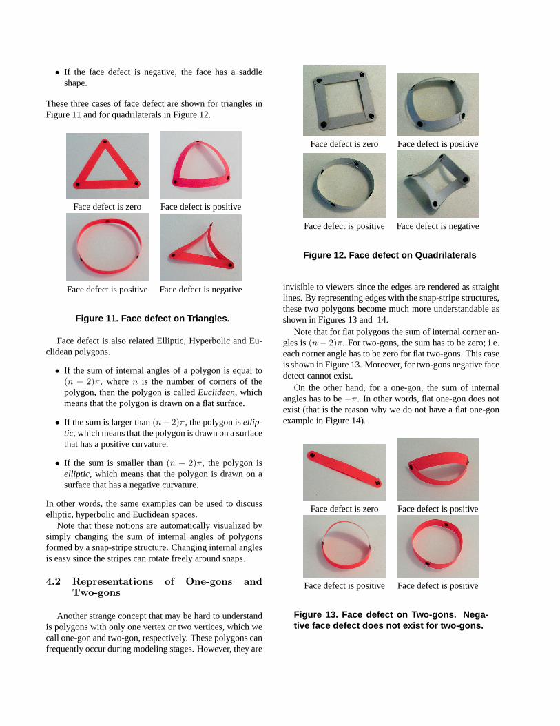
These three cases of face defect are shown for triangles inFigure 11 and for quadrilaterals in Figure 12.
Face defect is zero Face defect is positive
Face defect is positive Face defect is negative
Figure 11. Face defect on Triangles.
Face defect is also related Elliptic, Hyperbolic and Eu-clidean polygons.
• If the sum of internal angles of a polygon is equal to(n − 2)π, wheren is the number of corners of thepolygon, then the polygon is calledEuclidean, whichmeans that the polygon is drawn on a flat surface.
• If the sum is larger than(n− 2)π, the polygon isellip-tic, which means that the polygon is drawn on a surfacethat has a positive curvature.
• If the sum is smaller than(n − 2)π, the polygon iselliptic, which means that the polygon is drawn on asurface that has a negative curvature.
In other words, the same examples can be used to discusselliptic, hyperbolic and Euclidean spaces.
Note that these notions are automatically visualized bysimply changing the sum of internal angles of polygonsformed by a snap-stripe structure. Changing internal anglesis easy since the stripes can rotate freely around snaps.
4.2 Representations of One-gons andTwo-gons
Another strange concept that may be hard to understandis polygons with only one vertex or two vertices, which wecall one-gon and two-gon, respectively. These polygons canfrequently occur during modeling stages. However, they are
Face defect is zero Face defect is positive
Face defect is positive Face defect is negative
Figure 12. Face defect on Quadrilaterals
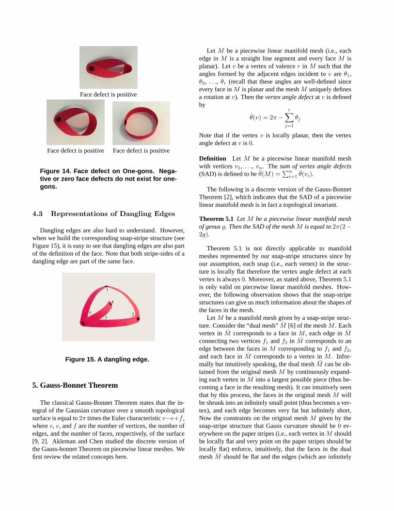
invisible to viewers since the edges are rendered as straightlines. By representing edges with the snap-stripe structures,these two polygons become much more understandable asshown in Figures 13 and 14.
Note that for flat polygons the sum of internal corner an-gles is(n− 2)π. For two-gons, the sum has to be zero; i.e.each corner angle has to be zero for flat two-gons. This caseis shown in Figure 13. Moreover, for two-gons negative facedetect cannot exist.
On the other hand, for a one-gon, the sum of internalangles has to be−π. In other words, flat one-gon does notexist (that is the reason why we do not have a flat one-gonexample in Figure 14).
Face defect is zero Face defect is positive
Face defect is positive Face defect is positive
Figure 13. Face defect on Two-gons. Nega-tive face defect does not exist for two-gons.
Face defect is positive
Face defect is positive Face defect is positive
Figure 14. Face defect on One-gons. Nega-tive or zero face defects do not exist for one-gons.
4.3 Representations of Dangling Edges
Dangling edges are also hard to understand. However,when we build the corresponding snap-stripe structure (seeFigure 15), it is easy to see that dangling edges are also partof the definition of the face. Note that both stripe-sides of adangling edge are part of the same face.
Figure 15. A dangling edge.
5. Gauss-Bonnet Theorem
The classical Gauss-Bonnet Theorem states that the in-tegral of the Gaussian curvature over a smooth topologicalsurface is equal to2π times the Euler characteristicv−e+f ,wherev, e, andf are the number of vertices, the number ofedges, and the number of faces, respectively, of the surface[9, 2]. Akleman and Chen studied the discrete version ofthe Gauss-bonnet Theorem on piecewise linear meshes. Wefirst review the related concepts here.
Let M be a piecewise linear manifold mesh (i.e., eachedge inM is a straight line segment and every faceM isplanar). Letv be a vertex of valencer in M such that theangles formed by the adjacent edges incident tov areθ1,θ2, . . ., θr (recall that these angles are well-defined sinceevery face inM is planar and the meshM uniquely definesa rotation atv). Then thevertex angle defectat v is definedby
θ(v) = 2π −r∑
j=1
θj
Note that if the vertexv is locally planar, then the vertexangle defect atv is 0.
Definition Let M be a piecewise linear manifold meshwith verticesv1, . . ., vn. Thesum of vertex angle defects(SAD) is defined to beθ(M) =
∑ni=1 θ(vi).
The following is a discrete version of the Gauss-BonnetTheorem [2], which indicates that the SAD of a piecewiselinear manifold mesh is in fact a topological invariant.
Theorem 5.1 Let M be a piecewise linear manifold meshof genusg. Then the SAD of the meshM is equal to2π(2−2g).
Theorem 5.1 is not directly applicable to manifoldmeshes represented by our snap-stripe structures since byour assumption, each snap (i.e., each vertex) in the struc-ture is locally flat therefore the vertex angle defect at eachvertex is always0. Moreover, as stated above, Theorem 5.1is only valid on piecewise linear manifold meshes. How-ever, the following observation shows that the snap-stripestructures can give us much information about the shapes ofthe faces in the mesh.
Let M be a manifold mesh given by a snap-stripe struc-ture. Consider the “dual mesh”M [6] of the meshM . Eachvertex inM corresponds to a face inM , each edge inMconnecting two verticesf1 andf2 in M corresponds to anedge between the faces inM corresponding tof1 andf2,and each face inM corresponds to a vertex inM . Infor-mally but intuitively speaking, the dual meshM can be ob-tained from the original meshM by continuously expand-ing each vertex inM into a largest possible piece (thus be-coming a face in the resulting mesh). It can intuitively seenthat by this process, the faces in the original meshM willbe shrunk into an infinitely small point (thus becomes a ver-tex), and each edge becomes very fat but infinitely short.Now the constraints on the original meshM given by thesnap-stripe structure that Gauss curvature should be0 ev-erywhere on the paper stripes (i.e., each vertex inM shouldbe locally flat and very point on the paper stripes should belocally flat) enforce, intuitively, that the faces in the dualmeshM should be flat and the edges (which are infinitely
short) should be straight line segments. Therefore, Theo-rem 5.1 should be applicable on the dual meshM . Nowthe vertex angle defect at each vertexf in the dual meshM reflects the face defect of the face in the original meshM that corresponds to the vertexf in M . This fact can bediscussed in a more formal way as follows.
Let M be the mesh represented by a snap-stripe struc-ture, and letM be the dual mesh. We say that the meshM and the dual meshM aregeometrically dualif for eachfacef in the meshM and its corresponding vertexvf inthe dual meshM , the face defect off is equal to the ver-tex angle defect ofvf . Note that this condition is naturallydefined and is automatically satisfied when all objects areplanar. Moreover, whenM andM are geometrically dual,the local geometric shape on a face inM is approximated bythe local geometric shape around the corresponding vertexin the dual meshM .
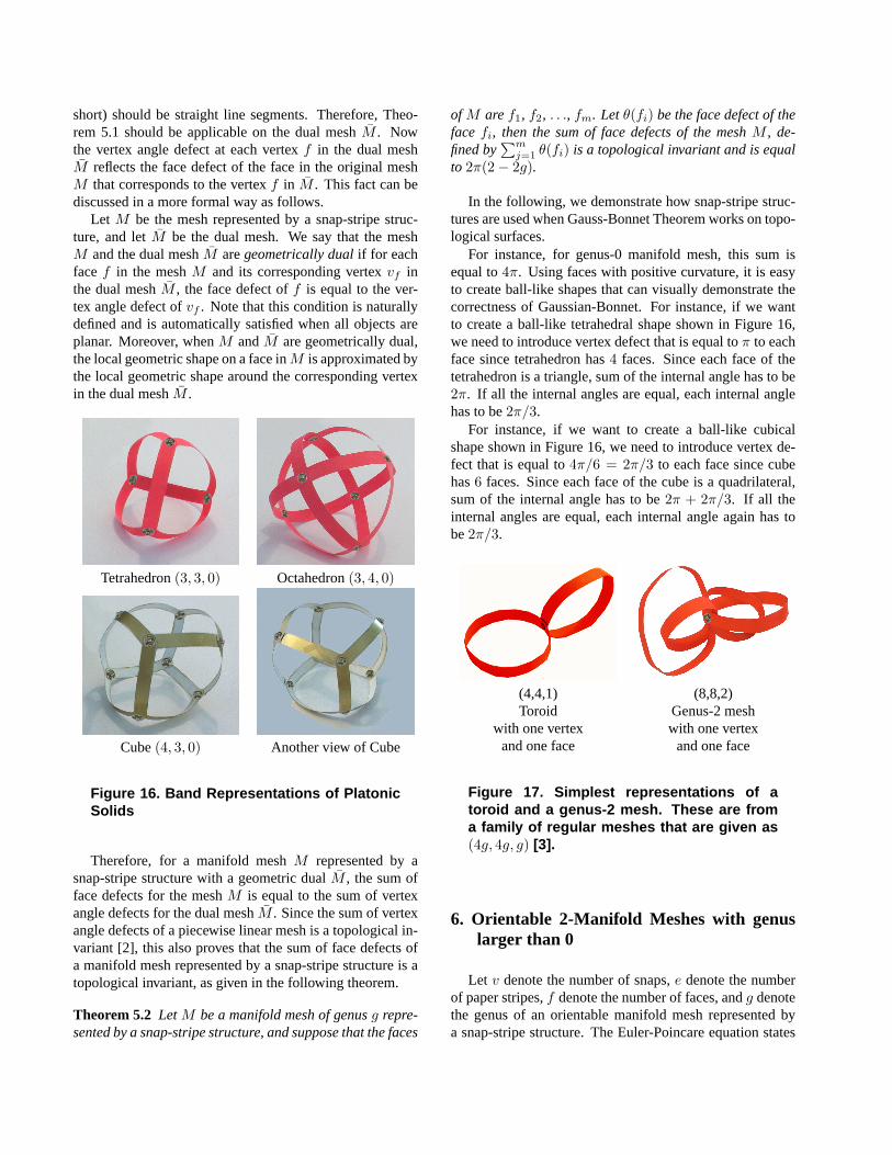
Tetrahedron(3, 3, 0) Octahedron(3, 4, 0)
Cube(4, 3, 0) Another view of Cube
Figure 16. Band Representations of PlatonicSolids
Therefore, for a manifold meshM represented by asnap-stripe structure with a geometric dualM , the sum offace defects for the meshM is equal to the sum of vertexangle defects for the dual meshM . Since the sum of vertexangle defects of a piecewise linear mesh is a topological in-variant [2], this also proves that the sum of face defects ofa manifold mesh represented by a snap-stripe structure is atopological invariant, as given in the following theorem.
Theorem 5.2 Let M be a manifold mesh of genusg repre-sented by a snap-stripe structure, and suppose that the faces
of M aref1, f2, . . ., fm. Letθ(fi) be the face defect of theface fi, then the sum of face defects of the meshM , de-fined by
∑mj=1 θ(fi) is a topological invariant and is equal
to 2π(2− 2g).
In the following, we demonstrate how snap-stripe struc-tures are used when Gauss-Bonnet Theorem works on topo-logical surfaces.
For instance, for genus-0 manifold mesh, this sum isequal to4π. Using faces with positive curvature, it is easyto create ball-like shapes that can visually demonstrate thecorrectness of Gaussian-Bonnet. For instance, if we wantto create a ball-like tetrahedral shape shown in Figure 16,we need to introduce vertex defect that is equal toπ to eachface since tetrahedron has4 faces. Since each face of thetetrahedron is a triangle, sum of the internal angle has to be2π. If all the internal angles are equal, each internal anglehas to be2π/3.
For instance, if we want to create a ball-like cubicalshape shown in Figure 16, we need to introduce vertex de-fect that is equal to4π/6 = 2π/3 to each face since cubehas6 faces. Since each face of the cube is a quadrilateral,sum of the internal angle has to be2π + 2π/3. If all theinternal angles are equal, each internal angle again has tobe2π/3.
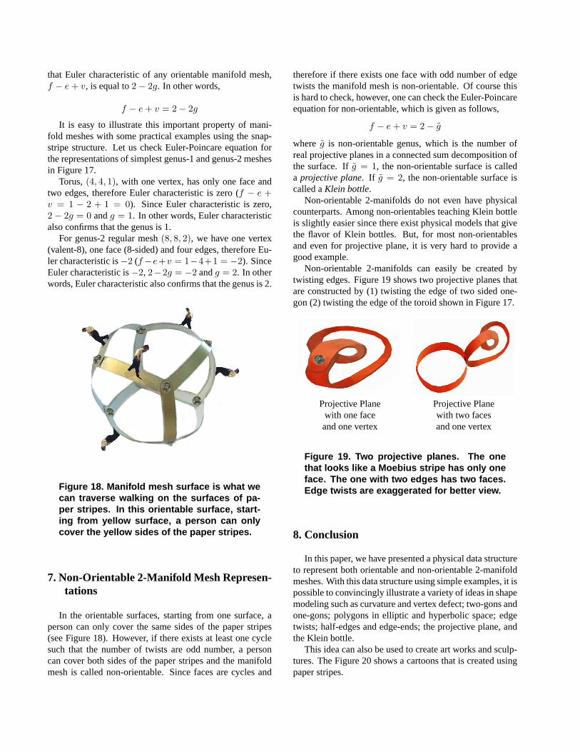
(4,4,1) (8,8,2)Toroid Genus-2 mesh
with one vertex with one vertexand one face and one face
Figure 17. Simplest representations of atoroid and a genus-2 mesh. These are froma family of regular meshes that are given as(4g, 4g, g) [3].
6. Orientable 2-Manifold Meshes with genuslarger than 0
Let v denote the number of snaps,e denote the numberof paper stripes,f denote the number of faces, andg denotethe genus of an orientable manifold mesh represented bya snap-stripe structure. The Euler-Poincare equation states
that Euler characteristic of any orientable manifold mesh,f − e + v, is equal to2− 2g. In other words,
f − e + v = 2− 2g
It is easy to illustrate this important property of mani-fold meshes with some practical examples using the snap-stripe structure. Let us check Euler-Poincare equation forthe representations of simplest genus-1 and genus-2 meshesin Figure 17.
Torus,(4, 4, 1), with one vertex, has only one face andtwo edges, therefore Euler characteristic is zero (f − e +v = 1 − 2 + 1 = 0). Since Euler characteristic is zero,2− 2g = 0 andg = 1. In other words, Euler characteristicalso confirms that the genus is 1.
For genus-2 regular mesh(8, 8, 2), we have one vertex(valent-8), one face (8-sided) and four edges, therefore Eu-ler characteristic is−2 (f−e+v = 1−4+1 = −2). SinceEuler characteristic is−2, 2−2g = −2 andg = 2. In otherwords, Euler characteristic also confirms that the genus is 2.
Figure 18. Manifold mesh surface is what wecan traverse walking on the surfaces of pa-per stripes. In this orientable surface, start-ing from yellow surface, a person can onlycover the yellow sides of the paper stripes.
7. Non-Orientable 2-Manifold Mesh Represen-tations
In the orientable surfaces, starting from one surface, aperson can only cover the same sides of the paper stripes(see Figure 18). However, if there exists at least one cyclesuch that the number of twists are odd number, a personcan cover both sides of the paper stripes and the manifoldmesh is called non-orientable. Since faces are cycles and
therefore if there exists one face with odd number of edgetwists the manifold mesh is non-orientable. Of course thisis hard to check, however, one can check the Euler-Poincareequation for non-orientable, which is given as follows,
f − e + v = 2− g
where g is non-orientable genus, which is the number ofreal projective planes in a connected sum decomposition ofthe surface. Ifg = 1, the non-orientable surface is calleda projective plane. If g = 2, the non-orientable surface iscalled aKlein bottle.
Non-orientable 2-manifolds do not even have physicalcounterparts. Among non-orientables teaching Klein bottleis slightly easier since there exist physical models that givethe flavor of Klein bottles. But, for most non-orientablesand even for projective plane, it is very hard to provide agood example.
Non-orientable 2-manifolds can easily be created bytwisting edges. Figure 19 shows two projective planes thatare constructed by (1) twisting the edge of two sided one-gon (2) twisting the edge of the toroid shown in Figure 17.
Projective Plane Projective Planewith one face with two facesand one vertex and one vertex
Figure 19. Two projective planes. The onethat looks like a Moebius stripe has only oneface. The one with two edges has two faces.Edge twists are exaggerated for better view.
8. Conclusion
In this paper, we have presented a physical data structureto represent both orientable and non-orientable 2-manifoldmeshes. With this data structure using simple examples, it ispossible to convincingly illustrate a variety of ideas in shapemodeling such as curvature and vertex defect; two-gons andone-gons; polygons in elliptic and hyperbolic space; edgetwists; half-edges and edge-ends; the projective plane, andthe Klein bottle.
This idea can also be used to create art works and sculp-tures. The Figure 20 shows a cartoons that is created usingpaper stripes.
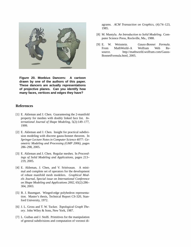
Figure 20. Moebius Dancers: A cartoondrawn by one of the authors of this paper.These dancers are actually representationsof projective planes. Can you identify howmany faces, vertices and edges they have?
References
[1] E. Akleman and J. Chen. Guaranteeing the 2-manifoldproperty for meshes with doubly linked face list.In-ternational Journal of Shape Modeling, 5(2):149–177,1999.
[2] E. Akleman and J. Chen. Insight for practical subdivi-sion modeling with discrete gauss-bonnet theorem. InSpringer Lecture Notes in Computer Science 4077: Ge-ometric Modeling and Processing (GMP 2006), pages286–298, 2005.
[3] E. Akleman and J. Chen. Regular meshes. InProceed-ings of Solid Modeling and Applications, pages 213–219, 2005.
[4] E. Akleman, J. Chen, and V. Srinivasan. A mini-mal and complete set of operators for the developmentof robust manifold mesh modelers.Graphical Mod-els Journal, Special issue on International Conferenceon Shape Modeling and Applications 2002, 65(2):286–304, 2003.
[5] B. J. Baumgart. Winged-edge polyhedron representa-tion. Master’s thesis, Technical Report CS-320, Stan-ford University, 1972.
[6] J. L. Gross and T. W. Tucker.Topological Graph The-ory. John Wiley & Sons, New York, 1987.
[7] L. Guibas and J. Stolfi. Primitives for the manipulationof general subdivisions and computation of voronoi di-
agrams. ACM Transaction on Graphics, (4):74–123,1985.
[8] M. Mantyla. An Introduction to Solid Modeling. Com-puter Science Press, Rockville, Ma., 1988.
[9] E. W. Weisstein. Gauss-Bonnet Formula.From MathWorld–A Wolfram Web Re-source. http://mathworld.wolfram.com/Gauss-BonnetFormula.html, 2005.