background statement for semi draft document 4978...
TRANSCRIPT

Background Statement for SEMI Draft Document 4978 Line Item Revision to SEMI S26-0709, Environmental, Health, and Safety Guideline for FPD Manufacturing System Note: This background statement is not part of the balloted item. It is provided solely to assist the recipient in reaching an informed decision based on the rationale of the activity that preceded the creation of this document. Note: Recipients of this document are invited to submit, with their comments, notification of any relevant patented technology or copyrighted items of which they are aware and to provide supporting documentation. In this context, “patented technology” is defined as technology for which a patent has issued or has been applied for. In the latter case, only publicly available information on the contents of the patent application is to be provided. Background:
The FPD System Safety Task Force proposes the line item changes to SEMI S26-0709. Major revisions were made to SEMI S2. These include the issues that should be reflected in S26. The following items in this proposed ballot are revised for the purpose of harmonization with SEMI S2:
• Evaluation for Design Review and Inspection • Exhaust Ventilation • Lifting Equipment and Mechanisms Supporting and Moving Hinged Loads
This ballot contains five line items as follows:
Line Item # Description of Line Item Line Item 1 Update of Referenced Standards and Documents Line Item 2 Revision to §8 “Evaluation for Design Review and Inspection” Line Item 3 Revision to “Lifting Equipment” and “Mechanisms Supporting and Moving
Hinged Loads” in §18 “Mechanical Design” Line Item 4 Revision to “Exhaust Ventilation”
Part A Revision to §21 “Exhaust Ventilation” Part B Moving Appendix 3 to Relation Information 3
Line Item 5
Editorial Changes Including Deletion of Underlines Background of Deletion of Underlines: Texts originated in SEMI S2-0706E and texts original to current SEMI S26 are differentiated by indicating the latter by underline in the current SEMI S26 as well as putting a Note explaining the meaning of underlines. Differences between SEMI S2 and SEMI S26 are considered to be well recognized by the industries as three years has passed since SEMI S26 was first published. Therefore, the underlines and the first Notes of the following sections of SEMI S26; Section 8-27, Appendix 1-8, and Related Information 1-2, Deletion of underlines in the following sections of SEMI S26; are deleted.
Throughout this ballot, text to be deleted is shown struck through and text to be added is shown underlined. Regarding Line Item 5, as there are many editorial changes throughout the document (even in some line items), they are differentiated by being highlighted in yellow.

The voting result of this ballot will be reviewed by the FPD System Safety Task Force (meeting date is TBD) and will be adjudicated at the Japan EHS Committee Meeting on Friday, December 3, 2010 during SEMICON Japan 2010 at Makuhari Messe, Chiba, Japan. If you have any questions, please contact to the FPD System Safety Task Force leaders as shown below: Naokatsu Nishiguchi (Co-Task Force Leader), [email protected], Ikuo Goto (Co-Task Force Leader), [email protected], or Akiko Yamamoto, SEMI Japan staff at [email protected].

Safety Checklist for SEMI Draft Document 4978 Line Item Revision to SEMI S26-0709, Environmental, Health, and Safety Guideline for FPD Manufacturing System Developing/Revising Body Name/Type: FPD System Safety Task Force Technical Committee: EHS Region: Japan Leadership Position Last First Affiliation Leader Goto Ikuo Muratec Automation Leader Nishiguchi Naokatsu Dainippon Screen Author/Editor* Mashiro Supika Tokyo Electron Checklist Author* * Only necessary if different from leaders Documents, Conflicts, and Consideration Safety related codes, standards, and practices used in developing the safety guideline, and the manner in which each item was considered by the technical committee # and Title Manner of Consideration SEMI E6 — Guide for Semiconductor Equipment Installation Documentation
Used as an example of information typically included in installation instructions.
SEMI F5 — Guide for Gaseous Effluent Handling
Used as an example of guidance in gaseous effluent handling
SEMI F14 — Guide for the Design of Gas Source System Enclosures
Used as an example of Guide for the Design of Gas Source System Enclosures
SEMI S1 — Safety Guideline for Equipment Safety Labels
Used as an example of Equipment Safety Labels
SEMI S2 — Environmental, Health, and Safety Guideline for Semiconductor Manufacturing Equipment
Referenced as guideline for safety design considerations for Semiconductor Manufacturing Equipment
SEMI S3 — Safety Guidelines for Process Liquid Heating Systems
Used as an example of safety design considerations for process liquid heating systems.
SEMI S6 — EHS Guideline for Exhaust Ventilation of Semiconductor Manufacturing Equipment
Used as an example of safety design considerations for Exhaust Ventilation.
SEMI S7 — Safety Guideline for Evaluation Personnel and Evaluating Company Qualifications
Used as an example of testing or evaluation of conformance.
SEMI S8 — Safety Guidelines for Ergonomics Engineering of Semiconductor Manufacturing Equipment
Used as an example of guidance for conformance to Ergonomics and Human Factors
SEMI S10 — Safety Guideline for Risk Assessment and Risk Evaluation Process
Referenced as guideline for Risk Assessment.

SEMI S13 — Environmental, Health and Safety Guideline for Documents Provided to the Equipment User for Use with Semiconductor Manufacturing Equipment
Used as an example of guidance for manual.
SEMI S14 — Safety Guidelines for Fire Risk Assessment and Mitigation for Semiconductor Manufacturing Equipment
Used as an example of guidance for Fire Risk Assessment.
SEMI S17 — Safety Guideline for Unmanned Transport Vehicle (UTV) Systems
Used as an example of guidance for AMHS safety.
SEMI S21 — Safety Guideline for Worker Protection
Used as an example of Safety Guideline for Worker Protection
SEMI S22 — Safety Guideline for the Electrical Design of Semiconductor Manufacturing Equipment
Used as an example of Electrical Design and Testing.
ANSI/ASME B18.15M — Metric Lifting Eyes
Used as an example of standards for lifting equipment
ANSI/ASME B30.20 — Below-the-Hook Lifting Devices
Used as an example of standards for lifting equipment
ANSI/AWS D14.1 — Specification for Welding of Industrial and Mill Cranes and Other Material Handling Equipment
Used as an example of standards for dynamic load testing of lifting equipment
ANSI/IEEE C95.1 — IEEE Standard for Safety Levels with Respect to Human Exposure to Radio Frequency Electromagnetic Fields, 3 kHz to 300 GHz
Referenced as standard for non-ionizing radiation (other than LASER) and fields test validation.
ANSI/RIA/ISO 10218-1 — Robots for Industrial Environment – Safety Requirements Part 1 – Robot
Used as an example of national or international robot standards.
ANSI/ISA SP84.01 — Application of Safety Instrumented Systems for the Process Industries
Used as an example of recognized standards for Fail-to-safe equipment control system (FECS).
CEN EN 1127-1 — Explosive atmospheres -- Explosion prevention and protection -- Part 1: Basic concepts and methodology
Used as an example of methods for making this assessment
CEN EN 1492 — Textile slings - Safety - Part 1: Flat woven webbing slings made of man-made fibres for general purpose use
Used as an example of standards for lifting equipment
IEC 60204-1 — Safety of Machinery – Electrical Equipment of Machines – Part 1: General Requirements
Used as an example of standards/ requirement of Electrical Design.
IEC 60825-1 — Safety of Laser Products – Part 1: Equipment Classification and Requirements
Used as an example of standards for Laser Products

IEC 61010-1 — Safety Requirements for Electrical Equipment for Measurement, Control, and Laboratory Use – Part 1: General Requirements
Used as an example of Machine Stability tests
IEC 61508 — Functional Safety of Electrical/Electronic/Programmable Electronic Safety-Related Systems
Used as an example of recognized standards for Fail-to-safe equipment control system (FECS).
IEC 62040-1-1:Uninterruptible Power Systems (UPS) Part 1-1: General and Safety Requirements for UPS Used in Operator Access Areas
Used as an example of recognized UPS standards
IEC 61672 — Electro acoustics –
Sound Level Meters Used as an example of the survey for Sound Pressure Level.
ISO 2415 — Forged shackles for general lifting purposes - Dee shackles and bow shackles
Used as an example of standards for lifting equipment
ISO 10218-1 — Robots for industrial environments -- Safety requirements -- Part 1: Robot
Used as an example of national or international robot standards.
ISO 11200 — Acoustics – Noise emitted by machinery and equipment – Guidelines for the use of basic standards for the determination of emission sound pressure levels at a work station and at other specified positions
Used as an example of the survey for Sound Pressure Level.
ISO 13849-1 — Safety of machinery – Safety-Related Parts of Control Systems – Part 1: General principles for design
Used as an example of recognized standards for Fail-to-safe equipment control system (FECS).
ISO 14121 — Safety of machinery – Risk assessment – Part 1: Principles
Used as an example of hazard analysis methods.
ISO 14122 — Safety of machinery. Permanent means of access to machinery
Used as an example of standard for ladders, stepladders and stairs
NFPA 12 — Standard on Carbon Dioxide Extinguishing Systems
Used as an example of CO2 fire suppression system
NFPA 70 — National Electrical Code Used as an example of guidance for ventilation design.
NFPA 72 — National Fire Alarm and Signaling Code
Used as an example of international or national codes or standards for fire detection, alarm and control system.
NFPA 497 — Classification of Flammable Liquids, Gases, or Vapors and of Hazardous (Classified) Locations for Electrical Installations in Chemical Process Areas
Used as an example of guidance for ventilation design.
NFPA 704 — Standard System for the Identification of the Hazards of Materials for Emergency Response
Used as an example of standard for ranking of hazardous production material (HPM)
UL 508A — Industrial Control Panels Used as an example of method of determining short circuit rating.
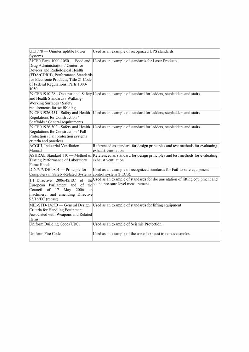
UL1778 — Uninterruptible Power Systems
Used as an example of recognized UPS standards
21CFR Parts 1000-1050 — Food and Drug Administration / Center for Devices and Radiological Health (FDA/CDRH), Performance Standards for Electronic Products, Title 21 Code of Federal Regulations, Parts 1000-1050
Used as an example of standards for Laser Products
29 CFR1910.28 - Occupational Safety and Health Standards / Walking-Working Surfaces / Safety requirements for scaffolding
Used as an example of standard for ladders, stepladders and stairs
29 CFR1926.451 - Safety and Health Regulations for Construction / Scaffolds / General requirements
Used as an example of standard for ladders, stepladders and stairs
29 CFR1926.502 - Safety and Health Regulations for Construction / Fall Protection / Fall protection systems criteria and practices
Used as an example of standard for ladders, stepladders and stairs
ACGIH, Industrial Ventilation Manual
Referenced as standard for design principles and test methods for evaluating exhaust ventilation
ASHRAE Standard 110 — Method of Testing Performance of Laboratory Fume Hoods
Referenced as standard for design principles and test methods for evaluating exhaust ventilation
DIN/V/VDE-0801 — Principle for Computers in Safety-Related Systems
Used as an example of recognized standards for Fail-to-safe equipment control system (FECS).
1.1 Directive 2006/42/EC of the European Parliament and of the Council of 17 May 2006 on machinery, and amending Directive 95/16/EC (recast)
Used as an example of standards for documentation of lifting equipment and sound pressure level measurement.
MIL-STD-1365B — General Design Criteria for Handling Equipment Associated with Weapons and Related Items
Used as an example of standards for lifting equipment
Uniform Building Code (UBC) Used as an example of Seismic Protection.
Uniform Fire Code Used as an example of the use of exhaust to remove smoke.

Known inconsistencies between the safety guideline and any other safety related codes, standards, and practices cited in the safety guideline # and Title Inconsistency with This Safety Guideline SEMI S2 — Environmental, Health, and Safety Guideline for Semiconductor Manufacturing Equipment
The scope of SEMI S2 is Semiconductor manufacturing equipment. The scope of this document is FPD manufacturing system. Since the equipment or the system to be evaluated is different, the criteria are different. In addition, the peculiar criteria for FPDMS are written in this document.
SEMI S2 — Environmental, Health, and Safety Guideline for Semiconductor Manufacturing Equipment
Section22: The items of the effort target for FPDMS have not been written in this document.
Other conflicts with known codes, standards, and practices or with commonly accepted safety and health principles to the extent practical # and Title Nature of Conflict with This Safety Guideline Participants and Contributors Last First Affiliation Nishiguchi Naokatsu Dainippon Screen Manufactruing Goto Ikuo Muratec Automation Mashiro Supika Tokyo Electron Ibuka Shigehito Tokyo Electron Aihara Hisashi Takenaka Corporation Sakura Hidetoshi Intel Crawford Moray Hatsuta Sugita Yoshihiro TUV Rheinland Japan Ron Macklin R. Macklin & Associates, LLC Kenji Yamagata DAIFUKU Eiji Nakatani SOKUDO
The content requirements of this checklist are documented in Section 14.2 of the Regulations Governing SEMI Standards Committees.

This is a draft document of the SEMI International Standards program. No material on this page is to be construed as an official or adopted standard. Permission is granted to reproduce and/or distribute this document, in whole or in part, only within the scope of SEMI International Standards committee (document development) activity. All other reproduction and/or distribution without the prior written consent of SEMI is prohibited.
Page 1 Doc. 4978 © SEMI®
Semiconductor Equipment and Materials International 3081 Zanker Road San Jose, CA 95134-2127 Phone:408.943.6900 Fax: 408.943.7943
LETT
ER (Y
ELLO
W) B
ALL
OT
DRAFTDocument Number: 4978
Date: 2010/10/15
SEMI Draft Document 4978 Line Item Revision to SEMI S26-0709, Environmental, Health, and Safety Guideline for FPD Manufacturing System
1 Purpose
1.1 This safety guideline is intended as a set of performance-based environmental, health and safety (EHS) considerations for FPD manufacturing system (FPDMS) including their subsystems.
2 Scope
2.1 Applicability — This guideline applies to FPDMS used to manufacture, measure, assemble, and test FPD products, and their subsystems
2.2 Contents — This document contains the following sections:
1. Purpose
2. Scope
3. Limitations
4. Referenced Standards and Documents
5. Terminology
6. Safety Philosophy
7. General Provisions
8. Evaluation for Design Review and Inspection
9. Documents Provided to User
10. Hazard Alert Labels
11. Safety Interlock Systems
12. Emergency Shutdown
13. Electrical Design
14. Fire Protection
15. Process Liquid Heating Systems
16. Ergonomics and Human Factors
17. Hazardous Energy Isolation (HEI)
18. Mechanical Design
19. Seismic Protection
20. AMHS in the FPDMS
21. Exhaust Ventilation
22. Environmental Consideration
23. Chemicals
24. Ionizing Radiation
25. Non-Ionizing Radiation and Fields
This is a draft document of the SEMI International Standards program. No material on this page is to be construed as an official or adopted standard. Permission is granted to reproduce and/or distribute this document, in whole or in part, only within the scope of SEMI International Standards committee (document development) activity. All other reproduction and/or distribution without the prior written consent of SEMI is prohibited.
Page 2 Doc. 4978 © SEMI®
Semiconductor Equipment and Materials International 3081 Zanker Road San Jose, CA 95134-2127 Phone:408.943.6900 Fax: 408.943.7943
LETT
ER (Y
ELLO
W) B
ALL
OT
DRAFTDocument Number: 4978
Date: 2010/10/15
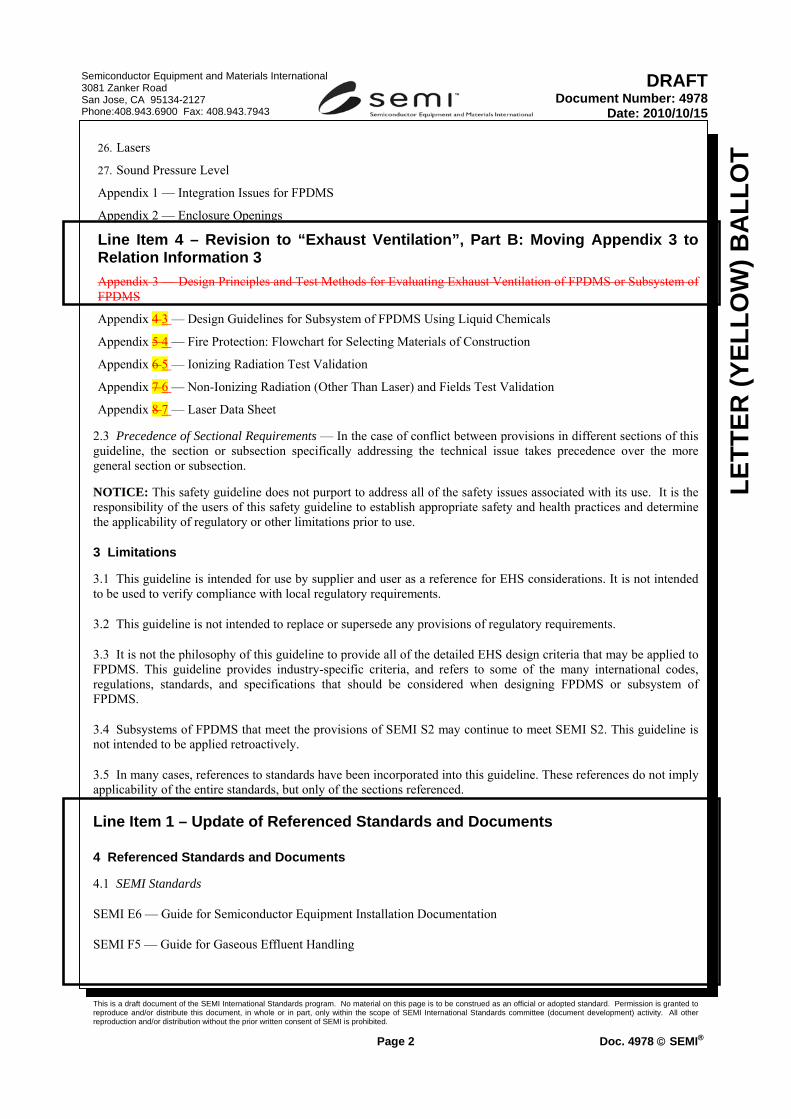
26. Lasers
27. Sound Pressure Level
Appendix 1 — Integration Issues for FPDMS
Appendix 2 — Enclosure Openings
Line Item 4 – Revision to “Exhaust Ventilation”, Part B: Moving Appendix 3 to Relation Information 3 Appendix 3 — Design Principles and Test Methods for Evaluating Exhaust Ventilation of FPDMS or Subsystem of FPDMS
Appendix 4 3 — Design Guidelines for Subsystem of FPDMS Using Liquid Chemicals
Appendix 5 4 — Fire Protection: Flowchart for Selecting Materials of Construction
Appendix 6 5 — Ionizing Radiation Test Validation
Appendix 7 6 — Non-Ionizing Radiation (Other Than Laser) and Fields Test Validation
Appendix 8 7 — Laser Data Sheet
2.3 Precedence of Sectional Requirements — In the case of conflict between provisions in different sections of this guideline, the section or subsection specifically addressing the technical issue takes precedence over the more general section or subsection.
NOTICE: This safety guideline does not purport to address all of the safety issues associated with its use. It is the responsibility of the users of this safety guideline to establish appropriate safety and health practices and determine the applicability of regulatory or other limitations prior to use.
3 Limitations
3.1 This guideline is intended for use by supplier and user as a reference for EHS considerations. It is not intended to be used to verify compliance with local regulatory requirements.
3.2 This guideline is not intended to replace or supersede any provisions of regulatory requirements.
3.3 It is not the philosophy of this guideline to provide all of the detailed EHS design criteria that may be applied to FPDMS. This guideline provides industry-specific criteria, and refers to some of the many international codes, regulations, standards, and specifications that should be considered when designing FPDMS or subsystem of FPDMS.
3.4 Subsystems of FPDMS that meet the provisions of SEMI S2 may continue to meet SEMI S2. This guideline is not intended to be applied retroactively.
3.5 In many cases, references to standards have been incorporated into this guideline. These references do not imply applicability of the entire standards, but only of the sections referenced.
Line Item 1 – Update of Referenced Standards and Documents
4 Referenced Standards and Documents
4.1 SEMI Standards
SEMI E6 — Guide for Semiconductor Equipment Installation Documentation
SEMI F5 — Guide for Gaseous Effluent Handling
This is a draft document of the SEMI International Standards program. No material on this page is to be construed as an official or adopted standard. Permission is granted to reproduce and/or distribute this document, in whole or in part, only within the scope of SEMI International Standards committee (document development) activity. All other reproduction and/or distribution without the prior written consent of SEMI is prohibited.
Page 3 Doc. 4978 © SEMI®
Semiconductor Equipment and Materials International 3081 Zanker Road San Jose, CA 95134-2127 Phone:408.943.6900 Fax: 408.943.7943
LETT
ER (Y
ELLO
W) B
ALL
OT
DRAFTDocument Number: 4978
Date: 2010/10/15
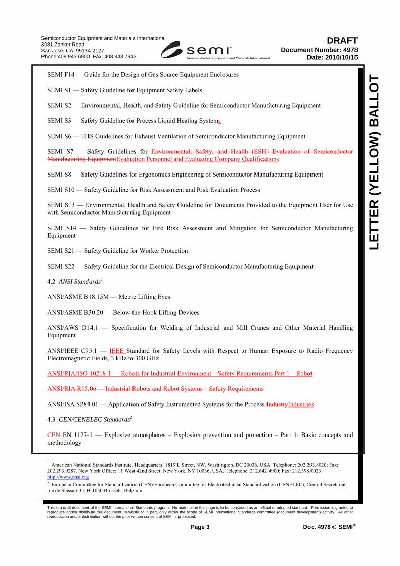
SEMI F14 — Guide for the Design of Gas Source Equipment Enclosures
SEMI S1 — Safety Guideline for Equipment Safety Labels
SEMI S2 — Environmental, Health, and Safety Guideline for Semiconductor Manufacturing Equipment
SEMI S3 — Safety Guideline for Process Liquid Heating Systems
SEMI S6 — EHS Guidelines for Exhaust Ventilation of Semiconductor Manufacturing Equipment
SEMI S7 — Safety Guidelines for Environmental, Safety, and Health (ESH) Evaluation of Semiconductor Manufacturing EquipmentEvaluation Personnel and Evaluating Company Qualifications
SEMI S8 — Safety Guidelines for Ergonomics Engineering of Semiconductor Manufacturing Equipment
SEMI S10 — Safety Guideline for Risk Assessment and Risk Evaluation Process
SEMI S13 — Environmental, Health and Safety Guideline for Documents Provided to the Equipment User for Use with Semiconductor Manufacturing Equipment
SEMI S14 — Safety Guidelines for Fire Risk Assessment and Mitigation for Semiconductor Manufacturing Equipment
SEMI S21 — Safety Guideline for Worker Protection
SEMI S22 — Safety Guideline for the Electrical Design of Semiconductor Manufacturing Equipment
4.2 ANSI Standards1
ANSI/ASME B18.15M — Metric Lifting Eyes
ANSI/ASME B30.20 — Below-the-Hook Lifting Devices
ANSI/AWS D14.1 — Specification for Welding of Industrial and Mill Cranes and Other Material Handling Equipment
ANSI/IEEE C95.1 — IEEE Standard for Safety Levels with Respect to Human Exposure to Radio Frequency Electromagnetic Fields, 3 kHz to 300 GHz
ANSI/RIA/ISO 10218-1 — Robots for Industrial Environment – Safety Requirements Part 1 – Robot
ANSI/RIA R15.06 — Industrial Robots and Robot Systems – Safety Requirements
ANSI/ISA SP84.01 — Application of Safety Instrumented Systems for the Process IndustryIndustries
4.3 CEN/CENELEC Standards2
CEN EN 1127-1 — Explosive atmospheres – Explosion prevention and protection – Part 1: Basic concepts and methodology
1 American National Standards Institute, Headquarters: 1819 L Street, NW, Washington, DC 20036, USA. Telephone: 202.293.8020; Fax: 202.293.9287. New York Office: 11 West 42nd Street, New York, NY 10036, USA. Telephone: 212.642.4900; Fax: 212.398.0023; http://www.ansi.org 2 European Committee for Standardization (CEN)/European Committee for Electrotechnical Standardization (CENELEC), Central Secretariat: rue de Stassart 35, B-1050 Brussels, Belgium

This is a draft document of the SEMI International Standards program. No material on this page is to be construed as an official or adopted standard. Permission is granted to reproduce and/or distribute this document, in whole or in part, only within the scope of SEMI International Standards committee (document development) activity. All other reproduction and/or distribution without the prior written consent of SEMI is prohibited.
Page 4 Doc. 4978 © SEMI®
Semiconductor Equipment and Materials International 3081 Zanker Road San Jose, CA 95134-2127 Phone:408.943.6900 Fax: 408.943.7943
LETT
ER (Y
ELLO
W) B
ALL
OT
DRAFTDocument Number: 4978
Date: 2010/10/15
CEN EN 1492 — Textile slings – Safety – Lifting slings for general service made from natural and man-made fiber ropes Textile slings - Safety - Part 1: Flat woven webbing slings made of man-made fibres for general purpose use
4.4 IEC Standards3
IEC 60204-1 — Safety of Machinery – Electrical Equipment of Machines – Part 1: General Requirements
IEC 60825-1 — Safety of Laser Products – Part 1: Equipment Classification, and Requirements, and User’s Guide
IEC 61010-1 — Safety Requirements for Electrical System Equipment for Measurement, Control, and Laboratory System Use – Part 1: General Requirements
IEC 61508 — Functional Safety of Electrical/Electronic/Programmable Electronic Safety-Related Systems
IEC 62040-1-1 — Uninterruptible power Power systems Systems (UPS) Part 1-1: General and safety Safety requirements Requirements for UPS used Used in oOperator access Access areasAreas
IEC 61672-1651 — Electro acoustics – Sound Level Meters
4.5 ISO Standards4
ISO 2415 — Forged shackles for general lifting purposes – Dee shackles and bow shackles
ISO 10218-1 — Robots for industrial environments – Safety requirements – Part 1: Robot
ISO 11200 — Acoustics – Noise emitted by machinery and equipment – Guidelines for the use of basic standards for the determination of emission sound pressure levels at a work station and at other specified positions
ISO 13849-1 — Safety of machinery – Safety-Related Parts of Control Systems – Part 1: General principles for design
ISO 14121 — Safety of machinery – Risk assessment – Part 1: PrinciplesPrinciples of risk assessment
ISO 14122 — Safety of machinery – Permanent means of access to machinery
4.6 NFPA Standards5
NFPA 12 — Standard on Carbon Dioxide Extinguishing Systems
NFPA 70 — National Electrical Code
NFPA 72 — National Fire Alarm and Signaling Code
NFPA 497 — Classification of Flammable Liquids, Gases, or Vapors and of Hazardous (Classified) Locations for Electrical Installations in Chemical Process AreasRecommended Practice for the Classification of Flammable Liquids, Gases, or Vapors and of Hazardous (Classified) Locations for Electrical Installations in Chemical Process Areas
3 International Electrotechnical Commission, 3 rue de Varembé, Case Postale 131, CH-1211 Geneva 20, Switzerland. Telephone: 41.22.919.02.11; Fax: 41.22.919.03.00; http://www.iec.ch 4 International Organization for Standardization, ISO Central Secretariat, 1 rue de Varembé, Case postale 56, CH-1211 Geneva 20, Switzerland. Telephone: 41.22.749.01.11; Fax: 41.22.733.34.30; http://www.iso.ch 5 National Fire Protection Association, 1 Batterymarch Park, Quincy, MA 02269, USA. Telephone: 617.770.3000; Fax: 617.770.0700; http://www.nfpa.org

This is a draft document of the SEMI International Standards program. No material on this page is to be construed as an official or adopted standard. Permission is granted to reproduce and/or distribute this document, in whole or in part, only within the scope of SEMI International Standards committee (document development) activity. All other reproduction and/or distribution without the prior written consent of SEMI is prohibited.
Page 5 Doc. 4978 © SEMI®
Semiconductor Equipment and Materials International 3081 Zanker Road San Jose, CA 95134-2127 Phone:408.943.6900 Fax: 408.943.7943
LETT
ER (Y
ELLO
W) B
ALL
OT
DRAFTDocument Number: 4978
Date: 2010/10/15
NFPA 704 — Standard System for the Identification of the Hazards of Materials for Emergency ResponseIdentification of the Fire Hazards of Materials
4.7 Underwriters Laboratories Standard6
UL 508A — Industrial Control Panels
UL 1778 — Uninterruptible Power Systems
4.8 US Code of Federal Regulations7
21CFR Parts 1000-1050 — Food and Drug Administration/Center for Devices and Radiological Health (FDA/CDRH), Performance Standards for Electronic Products, Title 21 Code of Federal Regulations, Parts 1000-1050
4.9 Council of the European Union Directives
Directive 2006/42/EC of the European Parliament and of the Council of 17 May 2006 on machinery, and amending Directive 95/16/EC (recast)
Directive 98/37/EC of the European Parliament and of the Council on 22 June 1998 on the approximation of the laws of the Member States relating to machinery
NOTE 1: This standard is commonly known as the Machinery Directive.
4.10 Other Standards and Documents
ACGIH, Industrial Ventilation Manual8
ASHRAE Standard 110 — Method of Testing Performance of Laboratory Fume Hoods9
DIN/V/VDE-0801 — Principle for Computers in Safety-Related Systems
MIL-STD-1365B — General Design Criteria for Handling Equipment Associated with Weapons and Related Items
Uniform Building Code (UBC)
NOTICE: Unless otherwise indicated, all documents cited shall be the latest published versions.
5 Terminology
5.1 Abbreviations and Acronyms
5.1.1 AMHS — Automated Material Handling System
5.1.2 EMO — Emergency Off
5.1.3 FECS — Fail-to-safe Equipment Control System
6 Underwriters Laboratory, 333 Pfingsten Rd, Northbrook, IL 60062, USA. Telephone: 877.854.3577; Fax: 847.407.1395; http://www.ul.com 7 United States Food and Drug Administration/ Center for Devices and Radiological Health (FDA/CDRH). Available from FDA/CDRH; http://www.accessdata.fda.gov/scripts/cdrh/cfdocs/cfcfr/cfrsearch.cfm 8 ACGIH, 1330 Kemper Meadow Road, Cincinnati, Ohio 45240, USA. http://www.acgih.org 9 ASHRAE, 1791 Tullie Circle, NE, Atlanta, Georgia 30329, USA. http://www.ashrae.org

This is a draft document of the SEMI International Standards program. No material on this page is to be construed as an official or adopted standard. Permission is granted to reproduce and/or distribute this document, in whole or in part, only within the scope of SEMI International Standards committee (document development) activity. All other reproduction and/or distribution without the prior written consent of SEMI is prohibited.
Page 6 Doc. 4978 © SEMI®
Semiconductor Equipment and Materials International 3081 Zanker Road San Jose, CA 95134-2127 Phone:408.943.6900 Fax: 408.943.7943
LETT
ER (Y
ELLO
W) B
ALL
OT
DRAFTDocument Number: 4978
Date: 2010/10/15
5.1.4 FPD — Flat Panel Display
5.1.5 FPDMS — FPD Manufacturing System
5.1.6 HEI — Hazardous Energy Isolation
5.1.7 LEL — Lower Explosive Limit
5.1.8 LFL — Lower Flammable Limit
5.1.9 MMI — Man Machine Interface
5.1.10 MPE — Maximum Permissible Exposure
5.1.11 NOHD — Nominal Ocular Hazard Distance
5.1.12 PES — Programmable Electronic System
5.1.13 PPE — Personal Protective Equipment
Line Item 4 – Revision to “Exhaust Ventilation”, Part A: Revision to §21 “Exhaust Ventilation”
5.1.14 SOC — Substance of Concern
5.2 Definitions
5.2.1 abort switch — a switch that, when activated, interrupts the activation sequence of a fire detection or fire suppression system. [SEMI S2]
5.2.2 adjusting — as applied to AMHS: (1) the act of tuning positioning devices such as sensors or mechanical limiters in order to define the operating zone for an AMHS, or (2) entering data (e.g., calibration values) into the memory of an automation device so that the device is able to use data points to determine the status of the device (e.g., location, presence of substrate) automatically.
5.2.3 accredited testing laboratory — an independent organization dedicated to the testing of components, devices, or systems; competent to perform evaluations based on established safety standards; and recognized by a governmental or regulatory body. [SEMI S2, SEMI S3, SEMI S14, SEMI S22]
5.2.4 automated material handling system — subsystem of FPDMS that moves substrates or cassettes within the FPDMS automatically by means of a robot, a vehicle, or a conveyor, etc., without being touched by someone’s hand.
5.2.5 baseline — for the purposes of this document, “baseline” refers to operating conditions, including process chemistry, for which the FPDMS’ subsystem was designed and manufactured.
5.2.6 breathing zone — imaginary globe, of 600 mm (two foot) radius, surrounding the head. [SEMI S2]
5.2.7 capture velocity — the air velocity that at any point in front of the exhausted hood or at the exhausted hood opening is necessary to overcome opposing air currents and to capture the contaminated air at that point by causing it to flow into the exhausted hood. [SEMI S2]
5.2.8 carcinogen — confirmed or suspected human cancer-causing agent as defined by the International Agency for Research on Cancer (IARC) or other recognized entities. [SEMI S2]
This is a draft document of the SEMI International Standards program. No material on this page is to be construed as an official or adopted standard. Permission is granted to reproduce and/or distribute this document, in whole or in part, only within the scope of SEMI International Standards committee (document development) activity. All other reproduction and/or distribution without the prior written consent of SEMI is prohibited.
Page 7 Doc. 4978 © SEMI®
Semiconductor Equipment and Materials International 3081 Zanker Road San Jose, CA 95134-2127 Phone:408.943.6900 Fax: 408.943.7943
LETT
ER (Y
ELLO
W) B
ALL
OT
DRAFTDocument Number: 4978
Date: 2010/10/15
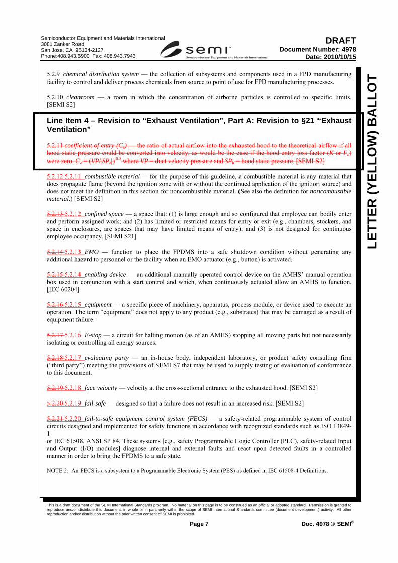
5.2.9 chemical distribution system — the collection of subsystems and components used in a FPD manufacturing facility to control and deliver process chemicals from source to point of use for FPD manufacturing processes.
5.2.10 cleanroom — a room in which the concentration of airborne particles is controlled to specific limits. [SEMI S2]
Line Item 4 – Revision to “Exhaust Ventilation”, Part A: Revision to §21 “Exhaust Ventilation”
5.2.11 coefficient of entry (Ce) — the ratio of actual airflow into the exhausted hood to the theoretical airflow if all hood static pressure could be converted into velocity, as would be the case if the hood entry loss factor (K or Fh) were zero. Ce = (VP/|SPh|) 0.5 where VP = duct velocity pressure and SPh = hood static pressure. [SEMI S2]
5.2.12 5.2.11 combustible material — for the purpose of this guideline, a combustible material is any material that does propagate flame (beyond the ignition zone with or without the continued application of the ignition source) and does not meet the definition in this section for noncombustible material. (See also the definition for noncombustible material.) [SEMI S2]
5.2.13 5.2.12 confined space — a space that: (1) is large enough and so configured that employee can bodily enter and perform assigned work; and (2) has limited or restricted means for entry or exit (e.g., chambers, stockers, and space in enclosures, are spaces that may have limited means of entry); and (3) is not designed for continuous employee occupancy. [SEMI S21]
5.2.14 5.2.13 EMO — function to place the FPDMS into a safe shutdown condition without generating any additional hazard to personnel or the facility when an EMO actuator (e.g., button) is activated.
5.2.15 5.2.14 enabling device — an additional manually operated control device on the AMHS’ manual operation box used in conjunction with a start control and which, when continuously actuated allow an AMHS to function. [IEC 60204]
5.2.16 5.2.15 equipment — a specific piece of machinery, apparatus, process module, or device used to execute an operation. The term “equipment” does not apply to any product (e.g., substrates) that may be damaged as a result of equipment failure.
5.2.17 5.2.16 E-stop — a circuit for halting motion (as of an AMHS) stopping all moving parts but not necessarily isolating or controlling all energy sources.
5.2.18 5.2.17 evaluating party — an in-house body, independent laboratory, or product safety consulting firm (“third party”) meeting the provisions of SEMI S7 that may be used to supply testing or evaluation of conformance to this document.
5.2.19 5.2.18 face velocity — velocity at the cross-sectional entrance to the exhausted hood. [SEMI S2]
5.2.20 5.2.19 fail-safe — designed so that a failure does not result in an increased risk. [SEMI S2]
5.2.21 5.2.20 fail-to-safe equipment control system (FECS) — a safety-related programmable system of control circuits designed and implemented for safety functions in accordance with recognized standards such as ISO 13849-1 or IEC 61508, ANSI SP 84. These systems [e.g., safety Programmable Logic Controller (PLC), safety-related Input and Output (I/O) modules] diagnose internal and external faults and react upon detected faults in a controlled manner in order to bring the FPDMS to a safe state.
NOTE 2: An FECS is a subsystem to a Programmable Electronic System (PES) as defined in IEC 61508-4 Definitions.
This is a draft document of the SEMI International Standards program. No material on this page is to be construed as an official or adopted standard. Permission is granted to reproduce and/or distribute this document, in whole or in part, only within the scope of SEMI International Standards committee (document development) activity. All other reproduction and/or distribution without the prior written consent of SEMI is prohibited.
Page 8 Doc. 4978 © SEMI®
Semiconductor Equipment and Materials International 3081 Zanker Road San Jose, CA 95134-2127 Phone:408.943.6900 Fax: 408.943.7943
LETT
ER (Y
ELLO
W) B
ALL
OT
DRAFTDocument Number: 4978
Date: 2010/10/15
5.2.22 5.2.21 failure — the termination of the ability of an item to perform a required function. Failure is an event, as distinguished from “fault,” which is a state. [SEMI S2, SEMI S22]
5.2.23 5.2.22 fault — the state of an item characterized by inability to perform a required function, excluding the inability during preventive maintenance or other planned actions, or due to lack of external resources. [SEMI S2]
5.2.24 5.2.23 fault-tolerant — designed so that a reasonably foreseeable single point failure does not result in an unsafe condition. [SEMI S2, SEMI S17, SEMI S22]
5.2.25 5.2.24 flammable gas — any gas that forms an ignitable mixture in air at 20°C (68°F) and 101.3 kPa (14.7 psia). [SEMI S2, SEMI S4, SEMI S18]
5.2.26 5.2.25 flammable liquid — a liquid having a flash point below 37.8°C (100°F). [SEMI S2, SEMI S3, SEMI S14]
5.2.27 5.2.26 flash point — the minimum temperature at which a liquid gives off sufficient vapor to form an ignitable mixture with air near the surface of the liquid, or within the test vessel used. [SEMI S2, SEMI S3]
5.2.28 5.2.27 FPD manufacturing system — system used to manufacture, assemble, or test FPD products. The FPDMS is constructed by integration of equipment that processes substrates (e.g., glass substrates, reticules), its component parts and its auxiliary, support, or peripheral equipment (e.g., chemical controllers, chemical distribution systems, vacuum pumps) and AMHS. Each piece of equipment or AMHS is the subsystem of the FPDMS. FPDMS also includes other items (e.g., structures, piping, ductwork, effluent/exhaust treatment systems, valve manifold boxes, filtration, and heaters) specific to the aforementioned system, but may not include such an item if the item is part of a facility and can support more than one piece of FPD manufacturing system.
5.2.29 5.2.28 gas cylinder cabinet — cabinet used for housing gas cylinders, and connected to gas distribution piping or to system using the gas. Synonym: gas cabinet. [SEMI S2]
5.2.30 5.2.29 gas panel — an arrangement of fluid handling components (e.g., valves, filters, mass flow controllers) that regulates the flow of fluids into the process. Synonyms: gas jungle, jungle, gas control valves, valve manifold. [SEMI S2]
5.2.31 5.2.30 gas panel enclosure — an enclosure designed to contain leaks from gas panel(s) within itself. Synonyms: jungle enclosure, gas box, valve manifold box. [SEMI S2]
5.2.32 5.2.31 harm — physical injury or damage to health of people, or damage to equipment, buildings, or environment. [SEMI S2, SEMI S10]
5.2.33 5.2.32 hazard — condition that has the potential to cause harm. [SEMI S2, SEMI S10]
5.2.34 5.2.33 hazardous non-ionizing radiation emissions — for the purposes of this guideline, non-ionizing radiation emissions outside the limits shown in Appendix 7 6 are considered hazardous.
5.2.35 5.2.34 hazardous production material (HPM) — a solid, liquid, or gas that has a degree-of-hazard rating in health, flammability, or reactivity of class 3 or 4 as ranked by NFPA 704 and which is used directly in research, laboratory, or production processes that have as their end product materials that are not hazardous . [SEMI S2]
5.2.36 5.2.35 hazardous voltage — unless otherwise defined by an appropriate international standard applicable to the system, voltages greater than 30 volts rms, 42.4 volts peak, 60 volts dc are defined in this document as hazardous voltage. [SEMI S2, SEMI S22]
NOTE 3: The specified levels are based on normal conditions in a dry location.

This is a draft document of the SEMI International Standards program. No material on this page is to be construed as an official or adopted standard. Permission is granted to reproduce and/or distribute this document, in whole or in part, only within the scope of SEMI International Standards committee (document development) activity. All other reproduction and/or distribution without the prior written consent of SEMI is prohibited.
Page 9 Doc. 4978 © SEMI®
Semiconductor Equipment and Materials International 3081 Zanker Road San Jose, CA 95134-2127 Phone:408.943.6900 Fax: 408.943.7943
LETT
ER (Y
ELLO
W) B
ALL
OT
DRAFTDocument Number: 4978
Date: 2010/10/15
Line Item 3 – Revision to “Lifting Equipment” and “Mechanisms Supporting and Moving Hinged Loads” in §18 “Mechanical Design”
NOTE 4:5.2.36 hinged load — a load supported by a hinge such that the hinge axis is not vertical. [SEMI S2]
Line Item 4 – Revision to “Exhaust Ventilation”, Part A: Revision to §21 “Exhaust Ventilation”
5.2.37 hood — in the context of § 21 and Appendix 3 of this guideline, “hood” means a shaped inlet designed to capture contaminated air and conduct it into an exhaust duct system. [SEMI S2]
5.2.38 hood entry loss factor (K or Fh) — a unitless factor that quantifies hood efficiency. If the hood is 100% efficient, then K or Fh = 0. Related equations:
Q = 12.65A[(SPh/d)/(1+Fh)] 0.5 (1)
where:
Q = volumetric flow rate in m3/sec
A = cross sectional area of the duct in m2
SPh = hood static pressure in Pa
d = density correction factor (unitless)
Q = 4.043A[(SPh/d)/(1+Fh)] 0.5 (2)
where:
Q = volumetric flow rate in m3/sec
A = cross sectional area of the duct in m2
SPh = hood static pressure in mm water gauge (w.g.)
d = density correction factor (unitless)
US units: Q = 4005A[(SPh/d)/(1+Fh)] 0.5 (3)
where:
Q = volumetric flow rate in cfm
A = cross sectional area of the duct in ft2
SPh = hood static pressure in inches water gauge (w.g.)
d = density correction factor (unitless)
5.2.39 5.2.38 incompatible — as applied to chemicals: in the context of § 23 of this guideline, describes chemicals that, when combined unintentionally, may react violently or in an uncontrolled manner, releasing energy that may create a hazardous condition. [SEMI S2]
5.2.40 5.2.39 intended reaction product — chemicals that are produced intentionally as a functional part of the FPD manufacturing process.
5.2.41 5.2.40 interlock — a mechanical, electrical or other type of device or system, the purpose of which is to prevent or interrupt the operation of specified machine elements under specified conditions. [SEMI S2]

This is a draft document of the SEMI International Standards program. No material on this page is to be construed as an official or adopted standard. Permission is granted to reproduce and/or distribute this document, in whole or in part, only within the scope of SEMI International Standards committee (document development) activity. All other reproduction and/or distribution without the prior written consent of SEMI is prohibited.
Page 10 Doc. 4978 © SEMI®
Semiconductor Equipment and Materials International 3081 Zanker Road San Jose, CA 95134-2127 Phone:408.943.6900 Fax: 408.943.7943
LETT
ER (Y
ELLO
W) B
ALL
OT
DRAFTDocument Number: 4978
Date: 2010/10/15
5.2.42 5.2.41 ionizing radiation — alpha particles, beta particles, gamma rays, X-rays, neutrons, high-speed electrons, high-speed protons, and other particles capable of producing ions in human tissue. [SEMI S2]
5.2.43 5.2.42 laser — any device that can be made to produce or amplify electromagnetic radiation in the wavelength range from 180 nm to 1 mm primarily by the process of controlled stimulated emission. [SEMI S2]
5.2.44 5.2.43 laser product — any product or assembly of components that constitutes, incorporates, or is intended to incorporate a laser or laser system (including laser diode), and that is not sold to another manufacturer for use as a component (or replacement for such component) of an electronic product. [SEMI S2]
5.2.45 5.2.44 laser source — any device intended for use in conjunction with a laser to supply energy for the excitation of electrons, ions, or molecules. General energy sources, such as electrical supply mains, should not be considered to be laser energy sources. [SEMI S2]
5.2.46 5.2.45 laser system — a laser in combination with an appropriate laser energy source, with or without additional incorporated components. [SEMI S2]
5.2.47 5.2.46 lifting accessory — a component (e.g., eyehook, shackle, hoist ring, wire rope, chain, or eyebolt) which is part of a lifting fixture or is attached directly between the lifting device and the load in order to lift it. [SEMI S2]
5.2.48 5.2.47 lifting device — a mechanical or electro-mechanical structure that is provided for the purpose of raising and lowering a load during maintenance or service tasks, and may be capable of moving the load in one or more horizontal directions. [SEMI S2]
5.2.49 5.2.48 lifting equipment — lifting devices, lifting fixtures and lifting accessories. [SEMI S2]
5.2.50 5.2.49 lifting fixture — a mechanical device or an assembly of lifting accessories (e.g., hoisting yoke, wire rope sling, webbing sling, or chain assembly) placed between the lifting device (but not permanently attached to it) and the load, in order to attach them to each other. [SEMI S2]
5.2.51 5.2.50 likelihood — the expected frequency with which harm will occur. Usually expressed as a rate (e.g., events per year, per product, or per substrate processed). [SEMI S2, SEMI S10]
5.2.52 5.2.51 local exhaust ventilation — local exhaust ventilation systems operate on the principle of capturing a contaminant at or near its source and moving the contaminant to the external environment, usually through an air cleaning or a destructive device. It is not to be confused with laminar flow ventilation. Synonyms: LEV, local exhaust, main exhaust, extraction system, module exhaust, individual exhaust. [SEMI S2]
5.2.53 5.2.52 lower flammable limit — the minimum concentration of a flammable substance in air through which a flame will propagate. [SEMI S6]
NOTE 4: The following pairs of terms are commonly used interchangeably:
• “lower explosive limit (LEL)” and “lower flammable limit (LFL),”
• “upper explosive limit (UEL) ” and “upper flammable limit (UFL),” and
• “explosive range” and “flammable range.”
SEMI S2 uses “LEL” as a synonym of LFL. However, “LEL,” “UEL,” or “explosive range” is sometimes used to designate concentrations to which a more specific criterion (e.g., a certain pressure rise or flame front speed) than the ability to propagate flame pertains.
5.2.54 5.2.53 maintenance — planned or unplanned activities intended to keep system in good working order. (See also the definition for service.)
This is a draft document of the SEMI International Standards program. No material on this page is to be construed as an official or adopted standard. Permission is granted to reproduce and/or distribute this document, in whole or in part, only within the scope of SEMI International Standards committee (document development) activity. All other reproduction and/or distribution without the prior written consent of SEMI is prohibited.
Page 11 Doc. 4978 © SEMI®
Semiconductor Equipment and Materials International 3081 Zanker Road San Jose, CA 95134-2127 Phone:408.943.6900 Fax: 408.943.7943
LETT
ER (Y
ELLO
W) B
ALL
OT
DRAFTDocument Number: 4978
Date: 2010/10/15
5.2.55 5.2.54 manual operation box — a handheld device connected by cable to an AMHS controller with which an AMHS can be programmed or moved.
NOTE 5: A manual operation box which has programming function may be called “a teach pendant” or “a teaching pendant.”
5.2.56 5.2.55 manuals — documents which describe necessary procedures and information for use with the FPD manufacturing system.
5.2.57 5.2.56 mass balance — a qualitative, and where possible, quantitative, specification of mass flow of input and output streams (including chemicals, gases, water, de-ionized water, compressed air, nitrogen, and by-products), in sufficient detail to determine the effluent characteristics and potential treatment options. [SEMI S2]
5.2.58 5.2.57 material safety data sheet (MSDS) — written or printed material concerning chemical elements and compounds, including hazardous materials, prepared in accordance with applicable standards. [SEMI S2]
5.2.59 5.2.58 maximum permissible exposure (MPE) — level of laser radiation to which, under normal circumstances, persons may be exposed without suffering adverse effects. [SEMI S2]
5.2.60 5.2.59 nominal ocular hazard distance (NOHD) — distance at which the beam irradiance or radiant exposure equals the appropriate corneal maximum permissible exposure (MPE). [SEMI S2]
5.2.61 5.2.60 noncombustible material — a material that, in the form in which it is used and under the conditions anticipated, will not ignite, burn, support combustion, or release flammable vapors when subjected to fire or heat. Typical noncombustible materials are metals, ceramics, and silica materials (e.g., glass and quartz). (See also the definition for combustible material.) [SEMI S2]
5.2.62 5.2.61 non-ionizing radiation — forms of electro-magnetic energy that do not possess sufficient energy to ionize human tissue by means of the interaction of a single photon of any given frequency with human tissue. Non-ionizing radiation is customarily identified by frequencies from zero hertz to 3 × 10¹⁵ hertz (wavelengths ranging from infinite to 100 nm). This includes: static fields (frequencies of 0 hertz and infinite wavelengths); extremely low frequency fields (ELF), which includes power frequencies; subradio-frequencies; radiofrequency/microwave energy; and infrared, visible, and ultraviolet energies. [SEMI S2]
5.2.63 5.2.62 non-recycling, deadman-type abort switch — a type of abort switch that must be constantly held closed for the abort of the fire detection or suppression system. In addition, it does not restart or interrupt any time delay sequence for the detection or suppression system when it is activated. [SEMI S2]
5.2.64 5.2.63 occupational exposure limits (OELs) — for the purpose of this document, OELs are generally established on the basis of an eight hour workday. Various terms are used to refer to OELs, such as permissible exposure levels, Threshold Limit Values®, maximum acceptable concentrations, maximum exposure limits, and occupational exposure standards. However, the criteria used in determining OELs can differ among the various countries that have established values. Refer to the national bodies responsible for the establishment of OELs. (Threshold Limit Value is a registered trademark of the American Conference of Governmental Industrial Hygienists.) [SEMI S2, SEMI F5]
5.2.65 5.2.64 operator — a person who interacts with the FPDMS only to the degree necessary for the FPDMS to perform its intended function.
5.2.66 5.2.65 parts-cleaning hood — exhausted hood used for the purpose of cleaning parts.
5.2.67 5.2.66 placed on the market — made physically available, regardless of the legal aspects of the act of transfer (loan, gift, sale, hire). [SEMI S2]
5.2.68 5.2.67 platform — a working space for persons, elevated above the surrounding floor or ground, such as a balcony for the operation or maintenance of machinery and FPDMS or its subsystem.

This is a draft document of the SEMI International Standards program. No material on this page is to be construed as an official or adopted standard. Permission is granted to reproduce and/or distribute this document, in whole or in part, only within the scope of SEMI International Standards committee (document development) activity. All other reproduction and/or distribution without the prior written consent of SEMI is prohibited.
Page 12 Doc. 4978 © SEMI®
Semiconductor Equipment and Materials International 3081 Zanker Road San Jose, CA 95134-2127 Phone:408.943.6900 Fax: 408.943.7943
LETT
ER (Y
ELLO
W) B
ALL
OT
DRAFTDocument Number: 4978
Date: 2010/10/15
NOTE 6: The top of FPDMS or subsystem of FPDMS may be considered platform in some instances.
5.2.69 5.2.68 positive-opening — as applied to electromechanical control devices: the achievement of contact separation as a direct result of a specified movement of the switch actuator through non-resilient members (i.e., contact separation is not dependent upon springs). [SEMI S2]
5.2.70 5.2.69 pyrophoric material — a chemical that will spontaneously ignite in air at or below a temperature of 54.4°C (130°F). [SEMI S2, SEMI S14]
5.2.71 5.2.70 radio frequency (rf) — electromagnetic energy with frequencies ranging from 3 kHz to 300 GHz. Micro-waves are a portion of rf extending from 300 MHz to 300 GHz. [SEMI S2]
5.2.72 5.2.71 readily accessible — capable of being reached quickly for operation or inspection, without requiring climbing over or removing obstacles, or using portable ladders, chairs, etc. [SEMI S2]
5.2.73 5.2.72 recognized — as applied to standards; agreed to, accepted, and practiced by a substantial international consensus. [SEMI S2]
5.2.74 5.2.73 rem — unit of dose equivalent. Most instruments used to measure ionizing radiation read in dose equivalent (rems or sieverts). 1 rem = 0.01 sievert. [SEMI S2]
5.2.75 5.2.74 repair — return the FPDMS or part of the FPDMS to a condition where it can perform its intended function through service.
5.2.76 5.2.75 reproductive toxicants — chemicals that are confirmed or suspected to cause statistically significant increased risk for teratogenicity, developmental effects, or adverse effects on embryo viability or on male or female reproductive function at doses that are not considered otherwise maternally or paternally toxic. [SEMI S2]
5.2.77 5.2.76 residual — as applied to risks or hazards: that which remains after engineering, administrative, and work practice controls have been implemented. [SEMI S2]
5.2.78 5.2.77 risk — the expected magnitude of losses from a hazard, expressed in terms of severity and likelihood. [SEMI S2]
5.2.79 5.2.78 safe shutdown condition — a condition in which all hazardous energy sources are removed or suitably contained and hazardous production materials are removed or contained, unless this results in additional hazardous conditions. [SEMI S2]
5.2.80 5.2.79 safety critical part — discrete device or component, such as used in a power or safety circuit, whose proper operation is necessary to the safe performance of the system or circuit. [SEMI S2]
5.2.81 5.2.80 service — unplanned activities intended to return system that has failed to good working order. (See also the definition for maintenance.)
5.2.82 5.2.81 severity — the extent of potential credible harm. [SEMI S2, SEMI S10]
5.2.83 5.2.82 short circuit current rating — the maximum available current to which the system supply circuit is intended, by the system manufacturer, to be connected.
NOTE 7: Short circuit current rating for an electrical system is typically based on the analysis of short circuit current ratings of the components within the system. See UL 508A and Related Information 2 of SEMI S22 for methods which may be used to determine short circuit current rating.
5.2.84 5.2.83 sievert (Sv) — unit of dose equivalent. Most instruments used to measure ionizing radiation read in dose equivalent (rems or sieverts). 1 Sv = 100 rems. [SEMI S2]

This is a draft document of the SEMI International Standards program. No material on this page is to be construed as an official or adopted standard. Permission is granted to reproduce and/or distribute this document, in whole or in part, only within the scope of SEMI International Standards committee (document development) activity. All other reproduction and/or distribution without the prior written consent of SEMI is prohibited.
Page 13 Doc. 4978 © SEMI®
Semiconductor Equipment and Materials International 3081 Zanker Road San Jose, CA 95134-2127 Phone:408.943.6900 Fax: 408.943.7943
LETT
ER (Y
ELLO
W) B
ALL
OT
DRAFTDocument Number: 4978
Date: 2010/10/15
Line Item 4 – Revision to “Exhaust Ventilation”, Part A: Revision to §21 “Exhaust Ventilation”
5.2.85 substance of concern (SOC), n. — a substance for which the equipment relies on exhaust ventilation to protect personnel from exposure above the limits established in SEMI S2 or to prevent formation of a mixture with air at above 25% of the LFL of the substance during normal operation, during maintenance, or in the case of failure. This includes substances meeting the criteria in the definition that are to be used in processes, those that are products or byproducts of intended or foreseeable reactions, those that are not intended to be directly involved in the processes (e.g., coolants) and those that are used only in maintenance or service (e.g., solutions used to clean process chambers). [SEMI S6]
5.2.86 5.2.84 supervisory alarm — as applied to fire detection or suppression systems: an alarm indicating a supervisory condition. [SEMI S2]
5.2.87 5.2.85 supervisory condition — as applied to fire detection or suppression systems: condition in which action or maintenance is needed to restore or continue proper function. [SEMI S2]
5.2.88 5.2.86 supplemental exhaust — local exhaust ventilation that is used intermittently for a specific task of finite duration. [SEMI S2]
5.2.89 5.2.87 supplier — party that provides a subsystem of an FPDMS to, and directly communicates with, the user. A supplier may be a manufacturer, a system distributor, or a system representative. (See also the definition for user.)
NOTE 7: A supplier can be supplier of some, or all of the subsystems of an FPDMS. A supplier can also be the system integrator.
5.2.90 5.2.88 system integrator — party that integrates various components (e.g., equipment, AMHS, etc.) and functional aspects into a system so that the integrated system (i.e., FPDMS) can perform its intended function. A system integrator can be the user of the FPDMS, or a supplier who is appointed to be the system integrator by contract.
5.2.91 5.2.89 testing — the term “testing” is used to describe measurements or observations used to validate and document conformance to designated criteria. [SEMI S2, SEMI S22]
5.2.92 5.2.90 toeboard — a vertical barrier at floor level erected along exposed edges of a floor opening, wall opening, platform, runway, or ramp to prevent falls of materials.
5.2.93 5.2.91 trouble alarm — as applied to fire detection or suppression systems: an alarm indicating a trouble condition. [SEMI S2]
5.2.94 5.2.92 trouble condition — as applied to fire detection or suppression systems: a condition in which there is a fault in a system, subsystem, or component that may interfere with proper function. [SEMI S2]
5.2.95 5.2.93 user — party that acquires FPDMS for the purpose of using it to manufacture FPDs. (See also the definition for supplier.)
5.2.96 5.2.94 velocity pressure (VP) — the pressure required to accelerate air from zero velocity to some velocity V. Velocity pressure is proportional to the kinetic energy of the air stream. Associated equations:
VP = (V/12.65) 2 (4)
where:
V = air velocity in m/s
VP = velocity pressure in Pa

This is a draft document of the SEMI International Standards program. No material on this page is to be construed as an official or adopted standard. Permission is granted to reproduce and/or distribute this document, in whole or in part, only within the scope of SEMI International Standards committee (document development) activity. All other reproduction and/or distribution without the prior written consent of SEMI is prohibited.
Page 14 Doc. 4978 © SEMI®
Semiconductor Equipment and Materials International 3081 Zanker Road San Jose, CA 95134-2127 Phone:408.943.6900 Fax: 408.943.7943
LETT
ER (Y
ELLO
W) B
ALL
OT
DRAFTDocument Number: 4978
Date: 2010/10/15
VP = (V/4.043) 2 (5)
where:
V = air velocity in m/s
VP = velocity pressure in mm water gauge (w.g.)
U.S. units: VP = (V/4005) 2 (6)
where:
V = velocity in feet per second
VP = velocity pressure in inches water gauge (w.g.)
Line Item 4 – Revision to “Exhaust Ventilation”, Part B: Moving Appendix 3 to Related Information 3
5.2.97 5.2.95 volumetric flow rate (Q) — in the context of § 21 and Appendix 3 of this guideline, Q = the volume of air exhausted per unit time. Associated equation: Q = VA, where V = air flow velocity, and A = the cross-sectional area of the duct or opening through which the air is flowing at standard conditions. [SEMI S2]
5.2.98 5.2.96 wet station — open surface tanks, enclosed in a housing, containing chemical materials used in the manufacturing of FPD materials. Synonyms: wet sink, wet bench, and wet deck.
5.2.99 5.2.97 yield strength — the stress at which a material exhibits a specified permanent deformation or set. This is the stress at which, the strain departs from the linear portion of the stress-strain curve by an offset unit strain of 0.002. [SEMI S2]
6 Safety Philosophy
6.1 A primary objective of the industry is to eliminate or control hazards during the FPDMS’ life cycle (i.e., the installation, start-up, operation, maintenance, service, and disposal of FPDMS).
6.2 The assumption is made that operators, maintenance personnel, and service personnel are trained in the tasks that they are intended to perform.
6.3 The following should be considered in the design and construction of FPDMS or a subsystem of FPDMS:
• regulatory requirements;
• industry standards;
• this guideline; and
• good engineering and manufacturing practices.
6.4 This guideline should be applied during the design, construction, and evaluation of FPDMS or subsystem of FPDMS, in order to reduce the expense and disruptive effects of redesign and retrofit.
6.5 No reasonably foreseeable single-point failure condition or operational error should allow exposure of personnel, facilities, or the community to hazards that could result in death, significant injury, or significant damage to the FPDMS or subsystem of FPDMS.
NOTE 8: The intent is to control single fault conditions that result in significant risks (i.e., Very High, High, or Medium risks based on the risk ranking matrix in SEMI S10).

This is a draft document of the SEMI International Standards program. No material on this page is to be construed as an official or adopted standard. Permission is granted to reproduce and/or distribute this document, in whole or in part, only within the scope of SEMI International Standards committee (document development) activity. All other reproduction and/or distribution without the prior written consent of SEMI is prohibited.
Page 15 Doc. 4978 © SEMI®
Semiconductor Equipment and Materials International 3081 Zanker Road San Jose, CA 95134-2127 Phone:408.943.6900 Fax: 408.943.7943
LETT
ER (Y
ELLO
W) B
ALL
OT
DRAFTDocument Number: 4978
Date: 2010/10/15
6.6 Safety features of FPDMS and subsystem of FPDMS should be fail-safe or of a fault-tolerant design and construction.
6.7 Components and assemblies should be used in accordance with their manufacturers’ ratings and specifications, where using them outside the ratings would create a safety hazard.
6.8 A hazard analysis should be performed to identify and evaluate hazards. The hazard analysis should be initiated early in the design phase, and updated as the design matures.
6.8.1 The hazard analysis should include consideration of:
• the application or process;
• the hazards associated with each task;
• anticipated failure modes;
• the probability of occurrence and severity of a harm;
• the level of expertise of exposed personnel and the frequency of exposure;
• the frequency and complexity of operating, servicing and maintenance tasks; and
• safety critical parts.
NOTE 9: ISO 14121 contains examples of hazard analysis methods.
6.8.2 The risks associated with hazards should be characterized using SEMI S10.
6.9 The order of precedence for resolving identified hazards should be as follows:
6.9.1 Design to Eliminate Hazards — From the initial concept phase, the supplier should design to eliminate hazards.
NOTE 10: It is recommended that the supplier continue to work to eliminate identified hazards.
6.9.2 Incorporate Safety Devices — If identified hazards cannot be eliminated or their associated risk adequately controlled through design selection, then the risk should be reduced through fixed, automatic, or other protective safety design features or devices.
NOTE 11: It is recommended that provisions be made for periodic functional checks of safety devices, when applicable.
6.9.3 Provide Warning Devices — If design or safety devices cannot effectively eliminate identified hazards or adequately reduce associated risk, a means should be used to detect the hazardous condition and to produce a warning signal to alert personnel of the hazard.
6.9.4 Provide Hazard Alert Labels — Where it is impractical to eliminate hazards through design selection or adequately reduce the associated risk with safety or warning devices, hazard alert labels should be provided. See § 10 for label information.
6.9.5 Develop Administrative Procedures and Training — Where hazards are not eliminated through design selection or adequately controlled with safety or warning devices or warning labels, procedures and training should be used. Procedures may include the use of personal protective equipment.
6.9.6 A combination of these approaches may be needed.

This is a draft document of the SEMI International Standards program. No material on this page is to be construed as an official or adopted standard. Permission is granted to reproduce and/or distribute this document, in whole or in part, only within the scope of SEMI International Standards committee (document development) activity. All other reproduction and/or distribution without the prior written consent of SEMI is prohibited.
Page 16 Doc. 4978 © SEMI®
Semiconductor Equipment and Materials International 3081 Zanker Road San Jose, CA 95134-2127 Phone:408.943.6900 Fax: 408.943.7943
LETT
ER (Y
ELLO
W) B
ALL
OT
DRAFTDocument Number: 4978
Date: 2010/10/15
7 General Provisions
7.1 This guideline should be incorporated by reference in purchase specifications of FPDMS or subsystem of FPDMS. The user and supplier should agree on deviations from this guideline.
7.2 The FPDMS must comply with laws and regulations that are in effect at the location of use. Any FPDMS or subsystem of FPDMS requiring certification or approval by government agencies must have this certification or approval as required by regulations.
NOTE 12: It is recommended that the supplier request from the user information regarding local laws and regulations.
7.3 The manufacturer should maintain a product safety program to identify and eliminate hazards or control risks in accordance with the order of precedence (see § 6.9).
7.3.1 The supplier should provide the user’s designated representative with bulletins that describe safety related upgrades or newly identified significant hazards associated with the subsystem of FPDMS. This should be done on an ongoing basis as needed.
7.4 Each supplier should review acceptability of each risk level of a component or an assembly provided by its supplier.
7.5 Model-specific tools and accessories necessary to operate, maintain, and service subsystem of FPDMS safely should be provided with the subsystem of FPDMS or specified by the supplier.
NOTE 13: The official values in this guideline are expressed in The International System of Units (SI). Values that:
• are enclosed in parentheses, and
• directly follow values expressed in SI units.
• are not official, are provided for reference only, and might not be exact conversions of the SI values.
7.6 The user is responsible for appointing a system integrator. The system integrator should ensure preparation of appropriate interlocks and EMOs for the integrated FPDMS.
7.7 If a safety interlock of any subsystem comprising an FPDMS needs to be overridden to perform any routine tasks, risk assessment should be performed for the FPDMS and risk reduction should be implemented as appropriate.
7.8 The system integrator should be responsible for FPDMS safety integration.
7.9 The system integrator should conduct a documented risk assessment and mitigate unacceptable risks generated by integration of FPDMS. Risk mitigating measures including administrative controls recommended for the user should be documented by the system integrator.
7.10 The system integrator should conduct risk assessment for AMHS incorporated in the FPDMS.
7.10.1 The system integrator should perform a risk assessment to determine the safety measures required for the final assembly of robot, load port, and associated system.
7.11 The system integrator should identify tools and accessories that become necessary by integration of the FPDMS to operate, maintain, and service FPDMS in addition to those provided or specified by the each supplier of subsystem. Specification for such tools and accessories should be communicated to the user by the system integrator.
8 Evaluation for Design Review and Inspection
NOTE 15: Texts originated in SEMI S2-0706E and texts original to this safety guideline are differentiated by indicating the latter by underline.

This is a draft document of the SEMI International Standards program. No material on this page is to be construed as an official or adopted standard. Permission is granted to reproduce and/or distribute this document, in whole or in part, only within the scope of SEMI International Standards committee (document development) activity. All other reproduction and/or distribution without the prior written consent of SEMI is prohibited.
Page 17 Doc. 4978 © SEMI®
Semiconductor Equipment and Materials International 3081 Zanker Road San Jose, CA 95134-2127 Phone:408.943.6900 Fax: 408.943.7943
LETT
ER (Y
ELLO
W) B
ALL
OT
DRAFTDocument Number: 4978
Date: 2010/10/15
8.1 This section describes evaluation of FPDMS or subsystem of FPDMS (e.g., equipment, AMHS etc.) to this guideline, and supporting information needed to perform the evaluation.
Line Item 2 – Revision to §8 “Evaluation for Design Review and Inspection”
8.2 General — The integrated FPDMS and each subsystem of the FPDMS should be evaluated by one or more evaluating parties according to this guideline. Each evaluating party should create a written evaluation report The evaluating party (see § 8.4) should evaluate the FPDMS and each subsystem of the FPDMS, and related end user documentation according to this guideline and create a written evaluation report.
NOTE 15:NOTE 14: The intent is that the “should” provisions of this guideline be used as the basis for evaluating conformance. The intent is also that the “may,” “suggested,” “preferred,” “recommended,” and “NOTE” provisions of this guideline not be used for evaluating conformance.
8.3 Conformance to specific sections paragraphs of SEMI S26 may be achieved by instructions included in the supplier’s installation instructions or other documentation of FPDMS or subsystem of FPDMS.
NOTE 16:NOTE 15: SEMI E6 contains types of information typically included in installation instructions.
8.4 Evaluation Report Contents: General — The evaluation report for each subsystem of the FPDMS should include the manuals (§ 9.4) and the design-specific sections (§§ 10–27), except criteria that are only applicable to the integrated FPDMS. Appendices 2–8 7 should be used in the evaluation, and referenced in the report, only as they pertain to the specific application. The evaluation report for the integrated FPDMS, should cover integration issues in accordance with Appendix 1 in addition to applicable criteria in the design-specific sections (§§ 10–27).
8.4.1 For each numbered paragraph, the evaluation report should state one of the following, and provide supporting rationale, according to the criteria in §§ 8.4.3 thru 8.4.5:
• “N/A”
• “Conforms to the Stated Criteria”
• “Conforms to the Performance Goal”
• “Does not Conform”
8.4.1 For each numbered section, the evaluation report should state one of the following, and provide supporting rationale:
•“Conforms” — FPDMS or subsystem of FPDMS conforms to the section or to the intent of the section.
•“Does not Conform” — FPDMS or subsystem of FPDMS conforms to neither the section nor to the intent of the section.
•“N/A” — Section is not applicable to FPDMS or subsystem of FPDMS.
EXCEPTION 1: If all of a particular section is found to be “N/A”, then the report may state the section is “N/A” rather than state “N/A” for each subordinate paragraph.
EXCEPTION 2: If the aspects of the FPDMS or the subsystem of the FPDMS to which a paragraph pertains are found to be a mix of “Conforms to the Stated Criteria” and “Conforms to the Performance Goal”, then both findings should be indicated in the report (with appropriate supporting rationale) instead of only one or the other.
NOTE 16: “Conforms to the Stated Criteria” and “Conforms to the Performance Goal” are both findings indicating conformance. The findings are differentiated, as the appropriate supporting rationale for these findings differs.
8.4.2 Within § 8.4, “FPDMS or subsystem of the FPDMS” means the FPDMS or the subsystem of the FPDMS under evaluation, or the related end user documentation provided with the FPDMS or the subsystem of the FPDMS, as appropriate. (See SEMI S13 for the meaning of “end user documentation.”)

This is a draft document of the SEMI International Standards program. No material on this page is to be construed as an official or adopted standard. Permission is granted to reproduce and/or distribute this document, in whole or in part, only within the scope of SEMI International Standards committee (document development) activity. All other reproduction and/or distribution without the prior written consent of SEMI is prohibited.
Page 18 Doc. 4978 © SEMI®
Semiconductor Equipment and Materials International 3081 Zanker Road San Jose, CA 95134-2127 Phone:408.943.6900 Fax: 408.943.7943
LETT
ER (Y
ELLO
W) B
ALL
OT
DRAFTDocument Number: 4978
Date: 2010/10/15
8.4.3 Not Applicable — A finding of “Not Applicable” should be given if the evaluator concludes there are no aspects of FPDMS or subsystem of the FPDMS to which the paragraph pertains.
8.4.4 Conformance Findings (“Conforms to the Stated Criteria” and “Conforms to the Performance Goal”)
8.4.4.1 A finding of “Conforms to the Stated Criteria” should be given if the evaluator concludes the aspects of the FPDMS or the subsystem of the FPDMS to which the paragraph pertains match the criteria stated in the text of the paragraph.
8.4.4.2 The supporting rationale for “Conforms to the Stated Criteria” should include a description of the aspects of the FPDMS or the subsystem of the FPDMS, and the objective information demonstrating the conformance of each to the criteria (e.g., testing, measurements, observation).
8.4.4.3 A finding of “Conforms to the Performance Goal” should be given if the evaluator concludes the aspects of the FPDMS or the subsystem of the FPDMS to which the paragraph pertains do not match the stated criteria, but they do meet the performance goal of the paragraph and they present a Low or Very Low Risk according to the risk assessment method of SEMI S10
8.4.4.4 The supporting rationale for “Conforms to the Performance Goal” should include:
8.4.4.4.1 a description of the aspects of the FPDMS or the subsystem of the FPDMS,
8.4.4.4.2 and, to support the conclusion of meeting the performance goal;
• a statement of the performance goal as it is understood by the evaluator,
• the logical argument which demonstrates the performance goal has been met,
• the objective evidence used to support the argument, and
• bibliographic information for references made in the argument (e.g., document title, website, reference number, author, publication date, revision).
8.4.4.4.3 and, to support the risk assessment;
• the specific hazards presented by the aspects of the FPDMS or the subsystem of the FPDMS,
• the scenarios in which the hazards are foreseen to cause harm,
• the harm foreseen in each scenario, and
• the severity and likelihood analyses for each scenario.
8.4.4.5 If a standard is used in whole or in part to support the performance goal argument, the supporting rationale should include information demonstrating why the standard is applicable, the section or sections used for the evaluation, and why the sections are relevant. For the purpose of this paragraph, a standard is applicable if the aspect of the FPDMS or the subsystem of the FPDMS under consideration is properly within scope, and the sections are relevant if they contain criteria having demonstrable bearing to the aspects of the FPDMS or the subsystem of the FPDMS (e.g., addressing similar design considerations).
8.4.5 Does Not Conform
8.4.5.1 A finding of “Does Not Conform” should be given if the evaluator concludes that one or more aspects of the FPDMS or the subsystem of the FPDMS:
• to which the paragraph pertains do not conform to the stated criteria and do not conform to the performance goal; or
This is a draft document of the SEMI International Standards program. No material on this page is to be construed as an official or adopted standard. Permission is granted to reproduce and/or distribute this document, in whole or in part, only within the scope of SEMI International Standards committee (document development) activity. All other reproduction and/or distribution without the prior written consent of SEMI is prohibited.
Page 19 Doc. 4978 © SEMI®
Semiconductor Equipment and Materials International 3081 Zanker Road San Jose, CA 95134-2127 Phone:408.943.6900 Fax: 408.943.7943
LETT
ER (Y
ELLO
W) B
ALL
OT
DRAFTDocument Number: 4978
Date: 2010/10/15
• for which there is insufficient information available to the evaluator to reach a conclusion for these or the “N/A” finding.
8.4.5.2 The supporting rationale for this finding should include a description of the non-conforming aspect(s) of the FPDMS or the subsystem of the FPDMS, a description of the non-conforming characteristics, and a determination per SEMI S10 of the associated risk; or a description of the information needed to reach a conclusion for one of the conformance findings or the “N/A” finding; as appropriate
NOTE 17: For example, “circuit breaker 42” is an aspect of the FPDMS or the subsystem of the FPDMS; “circuit breaker 42” being a supplementary overcurrent protector rather than a circuit breaker is a characteristic.
8.4.5.3 The evaluator may include any information they wish about remaining aspects of FPDMS or subsystem of the FPDMS which conform to the stated criteria or conform to the performance goal. None the less, it should be clear in the report that the overall finding is “Does Not Conform.”
8.4.1.1 The results of a risk assessment indicating no significant risk may be used in determining that the FPDMS or each subsystem of the FPDMS conforms to the intent of a section.
8.4.1.2 The evaluation report should include a determination per SEMI S10 of the level of risk associated with nonconformance findings.
8.5 Supporting rationale may include test data or documented engineering rationale.
8.6 8.5 Evaluation of Subsystem of FPDMS
NOTE 17:NOTE 18: It is recommended that the manufacturer’s typical configuration and process be used for evaluation purposes. Alternatively, a process agreed upon between the user and the supplier may be used.
NOTE 18:NOTE 19: Special options or configurations that may pose additional hazards and are not included in the initial evaluation may need a separate review. It is recommended that upgrades, retrofits, and other changes that affect the safety design of the subsystem of the FPDMS be evaluated for conformance, but generating a new or updated report may not be necessary for insignificant changes.
8.6.1 8.5.1 Supporting Information Provided to Evaluator — The following documentation should be provided to, or developed by, the evaluator, as necessary to demonstrate conformance to the provisions of this safety guideline.
8.6.1.1 8.5.1.1 General Information
• Written system description, including hardware configuration and function(s), power requirements, power output, and other information necessary to understand the design and operation of the subsystem.
• Engineering data used to provide the rationale that the subsystem and subassembly seismic anchorages are designed to satisfy the applicable design loads (see § 19, Seismic Protection).
• Descriptions of the purpose and function of safety devices, such as: emergency off devices (EMOs), interlocks, pressure relief devices, and limit controls.
• A hazard analysis (see § 6.8).
• Ergonomics evaluation (see § 16).
• A list of safety critical parts and, for each one, evidence of certification, or documentation showing that the component is suitable for its application.
• A residual fire risk assessment as described in § 14.2.
• Tests results, certifications, and design specifications that are necessary to evaluate the subsystem with respect to fire safety. Descriptions of the fire detection and suppression system and controls should also be provided.
8.6.1.2 8.5.1.2 Industrial Hygiene Information which should include, as applicable:

This is a draft document of the SEMI International Standards program. No material on this page is to be construed as an official or adopted standard. Permission is granted to reproduce and/or distribute this document, in whole or in part, only within the scope of SEMI International Standards committee (document development) activity. All other reproduction and/or distribution without the prior written consent of SEMI is prohibited.
Page 20 Doc. 4978 © SEMI®
Semiconductor Equipment and Materials International 3081 Zanker Road San Jose, CA 95134-2127 Phone:408.943.6900 Fax: 408.943.7943
LETT
ER (Y
ELLO
W) B
ALL
OT
DRAFTDocument Number: 4978
Date: 2010/10/15
• ventilation assessment (see § 21);
• chemical inventory and hazard analysis (see § 23);
• ionizing radiation assessment (see § 24);
• non-ionizing radiation assessment (see § 25);
• laser assessment (see § 26); and
• audio sound pressure level assessment (see § 27).
8.6.1.3 8.5.1.3 Environmental Information (see § 22)
• consideration of features that would promote reuse or refurbishing, or material recycling of the subsystem of the FPDMS and its components upon decommissioning;
• chemical selection methods and criteria (see§ 22.2);
• consideration of integrating effluent and emission controls into the subsystem of the FPDMS; and
• efforts to reduce wastes, effluents, emissions, and by-products.
8.6.2 8.5.2 Evaluation Report Contents: Other Information — The evaluation report for the subsystem of the FPDMS should also include:
• manufacturer’s model number;
• serial number of unit(s) evaluated;
• the date(s) that the subsystem was evaluated;
• subsystem description including configuration, options,
• essential diagrams; and
• a statement of the qualifications of the evaluating party.
8.7 8.6 Evaluation of Integrated FPDMS
NOTE 19:NOTE 20: Full system evaluation of the FPDMS may become possible only after the FPDMS is installed at the user’s fab. It is recommended that scope (e.g., which parts of the FPDMS or which parts of this guideline) of evaluation is mutually agreed upon among concerned parties (e.g., user ,suppliers, evaluating party, system integrator).
8.7.1 8.6.1 Supporting Information Provided to Evaluator — The following documentation should be provided to, or developed by, the evaluator, as necessary to demonstrate conformance of integrated FPDMS to the provisions of this safety guideline.
• Risk assessment information after integration
• System integrator’s name and affiliation
• Evaluation place, date, evaluator’s name and affiliation
• Integration schematic
• Integrated EMO circuit schematic
• Integrated interlock circuits schematic
• Schematic of operator control system for the FPDMS
• Alarm system schematic after integration
• Maintenance and service accessibility information

This is a draft document of the SEMI International Standards program. No material on this page is to be construed as an official or adopted standard. Permission is granted to reproduce and/or distribute this document, in whole or in part, only within the scope of SEMI International Standards committee (document development) activity. All other reproduction and/or distribution without the prior written consent of SEMI is prohibited.
Page 21 Doc. 4978 © SEMI®
Semiconductor Equipment and Materials International 3081 Zanker Road San Jose, CA 95134-2127 Phone:408.943.6900 Fax: 408.943.7943
LETT
ER (Y
ELLO
W) B
ALL
OT
DRAFTDocument Number: 4978
Date: 2010/10/15
8.7.2 8.6.2 If a third party evaluation is performed for the integrated FPDMS, system integrator should be available to the third party during evaluation of the FPDMS to provide detail information regarding the documentation in ¶ 8.76.1.
9 Documents Provided to User
NOTE 21: Texts originated in SEMI S2-0706E and texts original to this safety guideline are differentiated by indicating the latter by underline.
9.1 Evaluation Report — Upon request by the user, each supplier should provide the user with a summary of the SEMI S26 evaluation report or the full report.
9.2 Fire Protection Report — Upon request by the user, each supplier should provide the user with a summary of the fire protection report or the full report.
9.3 Environmental Documentation — The manufacturer should provide the user with the following environmental documentation as applicable:
9.3.1 Information regarding routes of unintended release (of effluents, wastes, emissions, and by-products) and methods and devices to monitor and control such releases. This should include information on features to monitor, prevent, and control unintended releases (see § 22.2.2).
9.3.2 Information regarding routes of intended release (of effluents, wastes, and emissions) and features to monitor and control such releases (see§ 22.2.3).
9.3.3 A list of items that become solid waste as a result of the operation, maintenance, and servicing of the equipment, and that are constructed of or contain substances whose disposal might be regulated (e.g., berylium-containing parts, vapor lamps, mercury switches, batteries, contaminated parts, maintenance wastes).
9.4 Manuals
9.4.1 Each supplier should provide the user with manuals based on the originally intended use as a subsystem of the FPDMS. The manuals should describe the scope and normal use of the subsystem of the FPDMS, and provide information to enable safe installation, operation, and maintenance of the subsystem of the FPDMS.
9.4.2 The system integrator should provide the user with manuals based on intended use of the FPDMS. The manuals should describe the scope and normal use of the FPDMS, and provide information to enable safe installation, integration, operation, and maintenance of the FPDMS.
9.4.2.1 The system integrator should ensure that information on energy isolation criteria and safety features for hazards shared between subsystems be easily identifiable and available so that service and maintenance personnel of any subsystem supplier can obtain such information from the user of the FPDMS.
NOTE 21: The assumption is that the user makes such information available to service and maintenance personnel of any subsystem supplier upon request.
9.4.3 The manuals should conform to SEMI S13.
9.4.4 Manuals should include technical descriptions in accordance with the provisions of each section of this document.
9.4.5 Seismic Information — Refer to § 19 of this document.

This is a draft document of the SEMI International Standards program. No material on this page is to be construed as an official or adopted standard. Permission is granted to reproduce and/or distribute this document, in whole or in part, only within the scope of SEMI International Standards committee (document development) activity. All other reproduction and/or distribution without the prior written consent of SEMI is prohibited.
Page 22 Doc. 4978 © SEMI®
Semiconductor Equipment and Materials International 3081 Zanker Road San Jose, CA 95134-2127 Phone:408.943.6900 Fax: 408.943.7943
LETT
ER (Y
ELLO
W) B
ALL
OT
DRAFTDocument Number: 4978
Date: 2010/10/15
Line Item 4 – Revision to “Exhaust Ventilation”, Part A: Revision to §21 “Exhaust Ventilation”
9.4.6 Industrial Hygiene Information — Refer to § 21 and §§ 23–27 of this document and to SEMI S6.
9.4.7 In addition to the provisions of SEMI S13, the manuals should include:
• specific written instructions on routine Type 4 tasks, excluding troubleshooting (refer to ¶ 13.3);
• instructions for hazardous energy isolation (HEI, “lockout/tagout”) (refer to § 17.2);
• descriptions of the emergency off (EMO) and safety interlock functions;
• a list of locations where work in confined space takes place;
• a list of maintenance tasks performed at confined space, such as inside of a chamber, design features ensuring safety of personnel during such tasks and recommended administrative controls;
• a list of locations where maintenance personnel could be exposed to asphyxiation hazards and recommended administrative measures to control risks associated with such hazards;
• a list of hazardous materials (e.g., lubricants, cleaners, coolants) required for maintenance, ancillary system or peripheral operations, including anticipated change-out frequency, quantity, and potential for contamination from the process;
• a list of items that become solid waste as a result of the operation, maintenance, and servicing of the FPDMS or subsystem of the FPDMS, and that are constructed of or contain substances whose disposal might be regulated (e.g., beryllium-containing parts, vapor lamps, mercury switches, batteries, contaminated parts, maintenance wastes);
• maintenance and troubleshooting procedures needed to maintain the effectiveness of safety design features or devices (i.e., engineering controls);
• information regarding potential routes of unintended releases (see § 22.2.2);
• residual hazardous materials, or parts likely to become contaminated with hazardous materials, that may be in the equipment at the time of end of use;
• instructions for proper use, maintenance, and inspection of lifting equipment supplied by the supplier of the subsystem of the FPDMS, including any guidance on specific inspection intervals. For lifting equipment specified or recommended, but not supplied, by the system integrator of the FPDMS or by the supplier of the subsystem of FPDMS, the documentation provided by the system integrator of the FPDMS or the supplier of the subsystem of FPDMS should specify that such instructions be obtained by the user from its lifting equipment supplier.
10 Hazard Alert Labels
NOTE 23: Texts originated in SEMI S2-0706E and texts original to this safety guideline are differentiated by indicating the latter by underline.
10.1 Where it is impractical to eliminate hazards through design selection or to reduce the associated risk adequately with safety or warning devices, hazard alert labels should be provided to identify and warn against hazards.
10.2 Labels should be durable and suitable for the environment of the intended use.
10.3 Labels should conform to SEMI S1.
EXCEPTION: Some hazard label formats and content are dictated by law (e.g., laser labeling and chemical hazard communication labeling in certain countries of use) and may not conform to SEMI S1.

This is a draft document of the SEMI International Standards program. No material on this page is to be construed as an official or adopted standard. Permission is granted to reproduce and/or distribute this document, in whole or in part, only within the scope of SEMI International Standards committee (document development) activity. All other reproduction and/or distribution without the prior written consent of SEMI is prohibited.
Page 23 Doc. 4978 © SEMI®
Semiconductor Equipment and Materials International 3081 Zanker Road San Jose, CA 95134-2127 Phone:408.943.6900 Fax: 408.943.7943
LETT
ER (Y
ELLO
W) B
ALL
OT
DRAFTDocument Number: 4978
Date: 2010/10/15
11 Safety Interlock Systems
NOTE 24: Texts originated in SEMI S2-0706E and texts original to this safety guideline are differentiated by indicating the latter by underline.
11.1 This section covers safety interlocks and safety interlock systems.
NOTE 24:NOTE 22: If a fire detection or suppression system is provided with the FPDMS or subsystem of the FPDMS, see § 14 for additional information.
11.2 Where appropriate, FPDMS or subsystem of FPDMS should use safety interlock systems that protect personnel, facilities, and the community from hazards inherent in the operation of the FPDMS.
NOTE 25:NOTE 23: Safety critical parts whose primary function is to protect the FPDMS (e.g., circuit breakers, fuses) are typically not considered to be safety interlocks.
11.3 Each FPDMS subsystem should be provided with interlock interfaces that allow for mitigation of foreseeable risks associated with hazards shared with other FPDMS subsystems.
11.3.1 The system integrator should verify that all safety interlocks provided for system integration are connected and operational prior to the FPDMS being used.
11.4 Safety interlock systems should be designed such that, upon activation of the interlock, the FPDMS, subsystem of the FPDMS or relevant parts of the subsystem, are automatically brought to a safe condition.
NOTE 26:NOTE 24: A safe condition may be achieved by bringing the FPDMS or subsystem of the FPDMS into appropriate category of stop function as indicated by the risk assessment and the functional requirement. The definition of three categories of stop function can be found in IEC 60204-1.
NOTE 27:NOTE 25: It is recommended that a safety interlock system is designed to provide safety performance appropriate for the risk level. ISO 13849-1 may be used to decide necessary level of safety performance for the interlock system in relation to a risk level.
11.5 Upon activation, the safety interlock should alert the operator immediately.
EXCEPTION: Alerting the operator is not expected if a safety interlock triggers the EMO circuit (see § 12) or otherwise removes power to the user interface.
NOTE 28:NOTE 26: An explanation of the cause is preferred upon activation of a safety interlock.
11.6 Safety interlock systems should be fault-tolerant and designed so that the functions or set points of the system components cannot be altered without disassembling, physically modifying, or damaging the device or component.
EXCEPTION: When safety interlock systems having adjustable set points or trip functions are used, access should be limited to maintenance or service personnel by requiring a deliberate action, such as using a tool or special keypad sequences, to access the adjustable devices or to adjust the devices.
NOTE 29:NOTE 27: This section does not address the defeatability of safety interlocks. See § 11.8 for additional information.
11.7 Electromechanical devices and components are preferred. Solid-state devices and solid state components may be used, provided that the safety interlock system, or relevant parts of the system, are evaluated for suitability for use in accordance with appropriate standard(s). The evaluation for suitability should take into consideration abnormal conditions such as overvoltage, undervoltage, power supply interruption, transient overvoltage, ramp voltage, electromagnetic susceptibility, electrostatic discharge, thermal cycling, humidity, dust, vibration, and jarring.
This is a draft document of the SEMI International Standards program. No material on this page is to be construed as an official or adopted standard. Permission is granted to reproduce and/or distribute this document, in whole or in part, only within the scope of SEMI International Standards committee (document development) activity. All other reproduction and/or distribution without the prior written consent of SEMI is prohibited.
Page 24 Doc. 4978 © SEMI®
Semiconductor Equipment and Materials International 3081 Zanker Road San Jose, CA 95134-2127 Phone:408.943.6900 Fax: 408.943.7943
LETT
ER (Y
ELLO
W) B
ALL
OT
DRAFTDocument Number: 4978
Date: 2010/10/15
EXCEPTION: Where the severity of a reasonably foreseeable harm is deemed to be Minor per SEMI S10, a software-based interlock may be considered suitable.
NOTE 30:NOTE 28: Where a safety interlock is provided to safeguard personnel from severe or catastrophic harm as categorized by SEMI S10, consideration of positive-opening type switches is recommended.
NOTE 31:NOTE 29: Evaluation for suitability for use may also include reliability, self-monitoring, and redundancy as addressed under standards such as NEMA ICS 1.1 and UL 991.
NOTE 32:NOTE 30: Solid-state devices include operational amplifiers, transistors, and integrated circuits.
11.7.1 FECS may be used in conjunction with electromechanical or solid state devices and components provided the programmable safety control system conforms to an appropriate standard for electronic safety systems. Components of the FECS should be tested and certified according to the requirements of the standard used. Examples of recognized electronic safety systems standards include IEC 61508, ISO 13849-1, ANSI/ISA SP84.01, and DIN/V/VDE-0801.
NOTE 33:NOTE 31: ¶ 13.4.3 states additional assessment criteria for safety-related components and assemblies.
NOTE 34:NOTE 32: A FECS is a subsystem of a Programmable Electronic System (PES). IEC 61508 is the preferred standard for complex PES.
11.8 The safety interlock system should be designed to minimize the need to override safety interlocks during maintenance activities.
11.8.1 Safety interlocks that safeguard personnel during normal operation tasks should not be defeatable without the use of a tool.
11.8.2 When maintenance access is necessary to areas protected by interlocks, defeatable safety interlocks may be used, provided that they require an intentional operation to bypass. Where practical, automatic activation of alternative risk mitigation means upon disabling of the interlocks may be considered.
11.8.2.1 In case of AMHS or robot, automatic activation of velocity limitation or hold to run upon defeating of safety interlock is recommended.
11.8.2.2 Upon exiting or completing the maintenance or service mode, all safety interlocks should be automatically restored.
EXCEPTION: Manual restoration of safety interlocks may be acceptable provided exiting service mode becomes possible only after restoration of safety interlocks.
11.8.2.3 If a safety interlock is defeated, the related maintenance or service instructions should identify residual risks associated with the task, the administrative controls necessary to safeguard the personnel for whom access is necessary, and other personnel who may also be endangered by the defeating of the safety interlock.
11.8.2.4 If a safety interlock is defeated at some subsystem of FPDMS, maintenance and service manuals should describe how to control hazard to workers who are working on other subsystem that links, connects, or shares a part with the subsystem of FPDMS.
11.9 The restoration of a safety interlock should not initiate system operation or parts movement where this can give rise to a hazardous condition.
11.10 Switches and other control device contacts should be connected to the ungrounded side of the circuit so that a short circuit to ground does not result in the interlocks being satisfied.

This is a draft document of the SEMI International Standards program. No material on this page is to be construed as an official or adopted standard. Permission is granted to reproduce and/or distribute this document, in whole or in part, only within the scope of SEMI International Standards committee (document development) activity. All other reproduction and/or distribution without the prior written consent of SEMI is prohibited.
Page 25 Doc. 4978 © SEMI®
Semiconductor Equipment and Materials International 3081 Zanker Road San Jose, CA 95134-2127 Phone:408.943.6900 Fax: 408.943.7943
LETT
ER (Y
ELLO
W) B
ALL
OT
DRAFTDocument Number: 4978
Date: 2010/10/15
11.11 Where a hazard to personnel is controlled through the use of an enclosure, the enclosure should either: require a tool to gain access and be labeled regarding the hazard against which it protects personnel; or be interlocked. In addition to enclosures, physical barriers at the point of hazard should be included where inadvertent contact is likely.
NOTE 35:NOTE 33: Where the removal of a cover exposes a hazard, consider additional labels. See § 10 for guidance.
12 Emergency Shutdown
NOTE 37: Texts originated in SEMI S2-0706E and texts original to this safety guideline are differentiated by indicating the latter by underline.
12.1 FPDMS should have an “emergency off” (EMO) circuit. The EMO actuator (e.g., button), when activated, should place the FPDMS into a safe shutdown condition, without generating any additional hazard to personnel or the facility.
EXCEPTION: An EMO circuit is not needed for FPDMS rated 2.4 kVA or less, where the hazards are only electrical in nature, provided that the main disconnect meets the accessibility provisions of ¶ 12.5.2 and that the effect of disconnecting the main power supply is equivalent to activating an EMO circuit.
NOTE 37:NOTE 34: It is recommended that the emergency off function not reduce the effectiveness of safety devices or of devices with safety-related functions (e.g., magnetic chucks or braking devices) necessary to bring the FPDMS to a safe shutdown condition effectively.
NOTE 38:NOTE 35: If a fire detection or suppression system is provided with the FPDMS or subsystem of the FPDMS, see § 14 for additional information.
12.1.1 Each subsystem of FPDMS should be provided with an EMO circuit, EMO actuator (e.g., button), and external EMO interface.
12.1.2 Each supplier should provide the system integrator with instructions for connecting the FPDMS’ subsystem external EMO interface to the EMO circuit of the FPDMS.
12.1.3 The system integrator should integrate EMO circuit of every subsystem comprising the FPDMS so that any EMO actuator of any subsystems of the FPDMS can place the FPDMS into a safe shutdown condition as described in § 12.1.
12.1.4 The system integrator should provide external EMO interface on the FPDMS with necessary instructions for connecting to the interface.
12.2 Activation of the emergency off circuit should de-energize all hazardous voltage and all power greater than 240 volt-amps in every system contained in the FPDMS beyond the main power enclosure.
EXCEPTION 1: A non-hazardous voltage EMO circuit (typically 24 volts) and its supply may remain energized.
EXCEPTION 2: Safety related devices (e.g., smoke detectors, gas/water leak detectors, pressure measurement devices) may remain energized from a non-hazardous power source.
EXCEPTION 3: A computer system performing data/alarm logging and error recovery functions may remain energized, provided that the energized breaker(s), receptacle(s), and each energized conductor termination are clearly labeled as remaining energized after EMO activation. Hazardous energized parts that remain energized after EMO activation should be insulated or guarded to prevent inadvertent contact by maintenance personnel.
12.2.1 The EMO circuit should not include features that are intended to allow it to be defeated or bypassed.
12.2.2 The EMO circuit should consist of electromechanical components.

This is a draft document of the SEMI International Standards program. No material on this page is to be construed as an official or adopted standard. Permission is granted to reproduce and/or distribute this document, in whole or in part, only within the scope of SEMI International Standards committee (document development) activity. All other reproduction and/or distribution without the prior written consent of SEMI is prohibited.
Page 26 Doc. 4978 © SEMI®
Semiconductor Equipment and Materials International 3081 Zanker Road San Jose, CA 95134-2127 Phone:408.943.6900 Fax: 408.943.7943
LETT
ER (Y
ELLO
W) B
ALL
OT
DRAFTDocument Number: 4978
Date: 2010/10/15
EXCEPTION 1: Solid-state devices and components may be used, provided the system or relevant parts of the system are evaluated and found suitable for use. The components should be evaluated and found suitable considering abnormal conditions such as over voltage, under voltage, power supply interruption, transient over voltage, ramp voltage, electromagnetic susceptibility, electrostatic discharge, thermal cycling, humidity, dust, vibration and jarring. The final removal of power should be accomplished by means of electromechanical components.
EXCEPTION 2: FECS may be used provided the FECS conforms to an appropriate standard for electronic safety systems. Components of the FECS should be tested and certified according to the requirements of the standard used. IEC 61508 and ISO 13849-1 are examples of internationally recognized electronic safety systems standards. The final removal of power should be accomplished by means of electromechanical components.
NOTE 39:NOTE 36: ¶ 13.4.3 states additional assessment criteria for safety-related components and assemblies.
NOTE 40:NOTE 37: An FECS is a subsystem of a Programmable Electronic System (PES). IEC 61508 is the preferred standard for complex PES.
12.2.3 All EMO circuits should be fault-tolerant.
12.2.4 Resetting an EMO actuator should not re-energize circuits or FPDMS.
12.2.5 The EMO circuit should shut down the FPDMS by de-energizing rather than energizing control components.
12.2.6 The EMO circuit should require manual resetting so that power cannot be restored automatically.
12.3 The emergency off button should be red and mushroom shaped. A yellow background for the EMO should be provided.
NOTE 41:NOTE 38: Non-lockable self-latching (i.e., twist- or pull-to-release) EMO buttons may be required by regulations.
12.3.1 Any other activator actuator that has only local or partial shut down function but not shut off FPDMS, should not use combination of red button with yellow background.
EXCEPTION: Red buttons with yellow background may be used on AMHS, provided such buttons are differentiated from EMO button by appearance.
12.4 All emergency off buttons should be clearly labeled as “EMO,” “Emergency Off,” or the equivalent text in local language should be clearly legible from the viewing location. The label may appear on the button or on the yellow background.
12.4.1 Any other activator actuator that has only local or partial shut down function but not shut off FPDMS, should not be labeled as “EMO,” “Emergency Off,” or the equivalent.
NOTE 42:NOTE 39: When several pieces of equipment or AMHS comprise of an FPDMS, removal of EMO label may be necessary if initial EMO button, which is capable of shutting down individual equipment or AMHS, is not able to shut down FPDMS.
12.5 Emergency off buttons should be readily accessible from operating and regularly scheduled maintenance locations and appropriately sized to enable activation by the heel of the palm.
12.5.1 Emergency off buttons should be located or guarded to minimize accidental activation.
12.5.2 No operation or regularly scheduled maintenance location should require more than 3 m (10 feet) travel to an EMO button.

This is a draft document of the SEMI International Standards program. No material on this page is to be construed as an official or adopted standard. Permission is granted to reproduce and/or distribute this document, in whole or in part, only within the scope of SEMI International Standards committee (document development) activity. All other reproduction and/or distribution without the prior written consent of SEMI is prohibited.
Page 27 Doc. 4978 © SEMI®
Semiconductor Equipment and Materials International 3081 Zanker Road San Jose, CA 95134-2127 Phone:408.943.6900 Fax: 408.943.7943
LETT
ER (Y
ELLO
W) B
ALL
OT
DRAFTDocument Number: 4978
Date: 2010/10/15
EXCEPTION: EMO button pendant may be provided for easy access from a location where incorporation of fixed EMO buttons is not practical for equipment operation but travel distance from periodic maintenance position exceeds 3 m or access to fixed EMO buttons can create other hazards.
NOTE 43:NOTE 40: Maintenance position in a vacuum chamber is an example of such location.
NOTE 44:NOTE 41: Provisions for EMO circuits described in § 12.2 and its subordinate sections are applied to EMO button pendant.
12.5.3 The person actuating or inspecting the EMO button should not be exposed to serious risks of tripping or falling or of coming in contact with energized electrical parts, moving machinery, or surfaces or objects operating at high temperatures, or exposure to other hazards.
12.6 See § 13.5 for additional EMO guidelines when EMOs are used with UPSs.
13 Electrical Design
NOTE 46: Texts originated in SEMI S2-0706E and texts original to this safety guideline are differentiated by indicating the latter by underline.
13.1 This section covers electrical and electronic systems in the FPDMS that uses hazardous voltages.
13.2 Types of Electrical Work — The following are the four types of electrical work defined by this safety guideline:
• Type 1 — System is fully de-energized.
• Type 2 — System is energized. Energized circuits are covered or insulated.
NOTE 46:NOTE 42: Type 2 work includes tasks where the energized circuits are or can be measured by placing probes through suitable openings in the covers or insulators.
• Type 3 — System is energized. Energized circuits are exposed and inadvertent contact with uninsulated energized parts is possible. Potential exposures are no greater than 30 volts rms, 42.4 volts peak, 60 volts dc or 240 volt-amps in dry locations.
• Type 4 — System is energized. Energized circuits are exposed and inadvertent contact with uninsulated energized parts is possible. Potential exposures are greater than 30 volts rms, 42.4 volts peak, 60 volts dc, or 240 volt-amps in dry locations. Potential exposures to radio-frequency currents, whether induced or via contact, exceed the limits in § A7A6-1 of Appendix 76.
13.3 Energized Electrical Work — Suppliers should design subsystems of the FPDMS to minimize the need to calibrate, modify, repair, test, adjust, or maintain them while they are energized, and to minimize work that must be performed on components near exposed energized circuits. The supplier should move as many tasks as practical from category Type 4 to Types 1, 2, or 3. Routine Type 4 tasks, excluding troubleshooting, should have specific written instructions in the maintenance manuals. General safety procedures (e.g., wearing appropriate personal protective equipment and establishing barriers) for troubleshooting, including Type 4 work, should be provided.
13.4 Electrical Design — FPDMS and their subsystems should conform to appropriate international, regional, national or industry product safety requirements.
NOTE 47:NOTE 43: Examples of such standards/requirement are IEC 60204-1 and SEMI S22.
13.4.1 Nonconductive or grounded conductive physical barriers should be provided:
• Where it is necessary to reach over, under, or around, or in close proximity to hazards.
• Where dropped objects could cause shorts or arcing.

This is a draft document of the SEMI International Standards program. No material on this page is to be construed as an official or adopted standard. Permission is granted to reproduce and/or distribute this document, in whole or in part, only within the scope of SEMI International Standards committee (document development) activity. All other reproduction and/or distribution without the prior written consent of SEMI is prohibited.
Page 28 Doc. 4978 © SEMI®
Semiconductor Equipment and Materials International 3081 Zanker Road San Jose, CA 95134-2127 Phone:408.943.6900 Fax: 408.943.7943
LETT
ER (Y
ELLO
W) B
ALL
OT
DRAFTDocument Number: 4978
Date: 2010/10/15
• Where failure of liquid fittings from any part of the subsystem of the FPDMS would result in the introduction of liquid into electrical parts.
• Over the line side of the main disconnect.
• Where maintenance or service tasks on the subsystem of the FPDMS in dry locations are likely to allow inadvertent contact with uninsulated energized parts containing either: potentials greater than 30 volts rms, 42.4 volts peak, or 60 volts dc; or power greater than 240 volt-amps.
NOTE 48:NOTE 44: A dry location can be considered to be one that is not normally subject to dampness or wetness.
NOTE 49:NOTE 45: Removable nonconductive and noncombustible covers are preferred.
13.4.2 Where test probe openings are provided in barriers, the barriers should be located, and the probe openings should be sized, to prevent inadvertent contact with adjacent energized parts, including the energized parts of the test probes.
13.4.3 Where failure of components and assemblies could result in a risk of electric shock, fire, or personal injury, those components and assemblies should be certified by an accredited testing laboratory, and used in accordance with the manufacturer’s specifications, or otherwise evaluated to the applicable standard(s).
13.4.3.1 When supplier-specified components or subassemblies are necessary for proper functioning of the safety features of the FPDMS’ subsystem, the necessity of using the specified components or subassemblies should be described in the maintenance manual.
13.4.4 Electrical wiring for power circuits, control circuits, grounding (earthing) and grounded (neutral) conductors should be color coded according to appropriate standard(s) per § 13.4, or labeled for easy identification at both ends of the wire. Where color is used for identification, it is acceptable to wrap conductor ends with appropriate colored tape or sleeving; the tape or sleeving should be reliably secured to the conductor.
EXCEPTION 1: Internal wiring on individual components (e.g., motors, transformers, meters, solenoid valves, power supplies).
EXCEPTION 2: Flexible cords.
EXCEPTION 3: Non hazardous voltage multi-conductor cables (e.g., ribbon cables).
EXCEPTION 4: When proper color is not available for conductors designed for special application (e.g., high-temperature conductors used for furnaces and ovens).
13.4.5 Grounding (earthing) conductors and connectors should be sized to be compatible in current rating with their associated ungrounded conductors according to appropriate criteria per § 13.4.
13.4.6 Electrical enclosures should be suitable for the environment in which they are intended to be used.
13.4.7 Enclosure openings should safeguard against personnel access to uninsulated energized parts. (Refer to Appendix 2 for examples of openings for protection against access from operators.)
13.4.8 Top covers of electrical enclosures should be designed and constructed to prevent objects from falling into the enclosures. (Refer to Appendix 2 for examples of acceptable top enclosure openings.)
13.4.9 The short circuit current rating of the subsystems of the FPDMS or their industrial control panels, for each supply circuit from the facility to the system, should be identified in the installation instructions.
13.4.10 Subsystems of the FPDMS should be provided with main overcurrent protection devices and main disconnect devices rated with an interrupting capacity of at least 10,000 rms symmetrical amperes interrupting
This is a draft document of the SEMI International Standards program. No material on this page is to be construed as an official or adopted standard. Permission is granted to reproduce and/or distribute this document, in whole or in part, only within the scope of SEMI International Standards committee (document development) activity. All other reproduction and/or distribution without the prior written consent of SEMI is prohibited.
Page 29 Doc. 4978 © SEMI®
Semiconductor Equipment and Materials International 3081 Zanker Road San Jose, CA 95134-2127 Phone:408.943.6900 Fax: 408.943.7943
LETT
ER (Y
ELLO
W) B
ALL
OT
DRAFTDocument Number: 4978
Date: 2010/10/15
capacity (AIC) for circuits rated 240VAC or less, and at least 14,000 rms symmetrical amperes interrupting capacity (AIC) for circuits more than 240VAC.
NOTE 50:NOTE 46: Some facilities may require higher AIC ratings due to electrical distribution system design.
EXCEPTION: Cord- and plug-connected single phase system, rated no greater than 240 volts line-to-line/150 volts line-to-ground and no greater than 2.4 kVA, may have overcurrent protection devices with interrupting capacity of at least 5,000 rms symmetrical amperes interrupting capacity (AIC).
13.4.11 Each subsystem of the FPDMS should be designed to receive incoming electrical power from the facility to a single feed location that terminates at the main disconnect specified in ¶ 13.4.10. This disconnect, when opened, should remove all incoming electrical power from the load side of the disconnect. The disconnect should also have the hazardous energy isolation (HEI, “lockout”) capabilities specified in § 17.
EXCEPTION 1: Subsystem of the FPDMS with more than one feed should be provided with provisions for HEI (lockout) for each feed and be marked with the following text or the equivalent at each disconnect: “WARNING: Risk of Electric Shock or Burn. Disconnect all [number of feed locations] sources of supply prior to servicing.” It is preferred that all of the disconnects for a subsystem of the FPDMS be grouped in one location.
EXCEPTION 2: Multiple units mounted separately with no shared hazards and without interconnecting circuits with hazardous voltages, energy levels or other hazardous conditions may have separate sources of power and separate supply circuit disconnect means, if they are clearly identified;
13.4.12 When a subsystem of the FPDMS can be controlled both from FPDMS controller and from local controls (e.g., by the controls of the subsystem itself, or by a local manual operation box), a lockable hardware-based device should be provided on or adjacent to the subsystem in order for selecting control sources.
EXCEPTION: The control source selection hardware-based device on the manual operation box of the AMHS is not required to be lockable if the manual operation box satisfies ¶ 20.3.1.2.1.
13.4.13 A permanent nameplate listing the manufacturer’s name, machine serial number, supply voltage, number of phases, frequency, short circuit current rating of the subsystem of the FPDMS or its industrial control panel, and full-load current should be attached to the subsystem of the FPDMS where plainly visible after installation. Where more than one incoming supply circuit is to be provided, the nameplate(s) should state the above information for each circuit.
NOTE 51:NOTE 47: Additional nameplate information may be required depending on the location of use.
13.5 Uninterruptible Power Supplies (UPSs) — This section applies to UPSs with outputs greater than: 30 volts rms, 42.4 volts peak; 60 volts dc; or 240 volt-amps.
13.5.1 Whenever a UPS is provided with a subsystem of the FPDMS, its location and wiring should be clearly described within the installation and maintenance manual.
13.5.2 Power from the UPS should be interrupted when any of the following events occur:
• the emergency off actuator (button) is pushed; or
• the main system disconnect is opened; or
• the main circuit breaker is opened.
EXCEPTION: Upon EMO activation, the UPS may supply power to the EMO circuit, safety related devices, and data/alarm logging computer systems as described in the exception clauses of § 12.2.
13.5.3 The UPS may be physically located within the footprint of the subsystem of the FPDMS provided that the UPS is within its own enclosure and is clearly identified.
This is a draft document of the SEMI International Standards program. No material on this page is to be construed as an official or adopted standard. Permission is granted to reproduce and/or distribute this document, in whole or in part, only within the scope of SEMI International Standards committee (document development) activity. All other reproduction and/or distribution without the prior written consent of SEMI is prohibited.
Page 30 Doc. 4978 © SEMI®
Semiconductor Equipment and Materials International 3081 Zanker Road San Jose, CA 95134-2127 Phone:408.943.6900 Fax: 408.943.7943
LETT
ER (Y
ELLO
W) B
ALL
OT
DRAFTDocument Number: 4978
Date: 2010/10/15
13.5.4 The UPS should be certified by an accredited testing laboratory and be suitable for its intended environment (e.g., damp location, exposure to corrosives) or otherwise evaluated to the applicable standard(s) for UPS. Examples of recognized UPS standards include IEC 62040 part 1-1 and UL1778.
13.5.4.1 Nationally approved UPS may be used if country where the place of use is located adopts national approval system, provided suitability for intended use of the UPS was tested and confirmed.
13.5.5 The UPS wiring should be identified as “UPS Output” or equivalent at each termination point where the UPS wiring can be disconnected.
13.6 Electrical Safety Tests
13.6.1 Each subsystem of the FPDMS connected to the facility branch circuit with a cord and plug should not exhibit surface leakage current greater than 3.5 milliampere (mA) as determined by testing completed in accordance with “Leakage Current Test for Cord-and-Plug Equipment” in SEMI S22, Testing section.
EXCEPTION: Subsystem of the FPDMS with leakage current exceeding 3.5 mA is acceptable if documentation is provided to substantiate that the system or the component is fully compliant with an applicable product safety standard that explicitly permits a higher leakage current.
13.6.2 All protective grounding circuits should have a measured resistance of one-tenth (0.1) ohm or less as determined by testing in accordance with “Earthing Continuity and Continuity of the Protective Bonding Circuit Test” in SEMI S22.
EXCEPTION: Alternatively, continuity of the protective bonding circuit may be verified by test specified in IEC 60204-1 or other applicable electrical safety standards.
13.7 Subsystem of the FPDMS in which flammable liquids or gases are used should be assessed to determine if additional precautions (e.g., purging) in the electrical design are necessary.
Line Item 1 – Update of Referenced Standards and Documents
NOTE 52:NOTE 48: NFPA 497 and CEN EN 1127-1 provide methods for making this assessment.
13.8 Earth Leakage Protection Devices — Earth leakage protection may be considered only as a secondary protection means.
NOTE 53:NOTE 49: In some location of use, incorporation of leakage protection devices is regulatory requirement.
NOTE 54:NOTE 50: Related Information 2 provides additional information on applications of Earth Leakage Protection Devices design.
14 Fire Protection
NOTE 56: Texts originated in SEMI S2-0706E and texts original to this safety guideline are differentiated by indicating the latter by underline.
14.1 Overview — This section provides minimum EHS considerations for protection from fire involving FPDMS or any subsystem of the FPDMS arising from the hazards contained within the FPDMS or any subsystem of the FPDMS.
14.1.1 This section provides minimum EHS considerations for fire protection designs and controls on the FPDMS or any subsystem of the FPDMS.

This is a draft document of the SEMI International Standards program. No material on this page is to be construed as an official or adopted standard. Permission is granted to reproduce and/or distribute this document, in whole or in part, only within the scope of SEMI International Standards committee (document development) activity. All other reproduction and/or distribution without the prior written consent of SEMI is prohibited.
Page 31 Doc. 4978 © SEMI®
Semiconductor Equipment and Materials International 3081 Zanker Road San Jose, CA 95134-2127 Phone:408.943.6900 Fax: 408.943.7943
LETT
ER (Y
ELLO
W) B
ALL
OT
DRAFTDocument Number: 4978
Date: 2010/10/15
14.1.2 This section also provides minimum considerations for fire detection and suppression systems when provided with the FPDMS or subsystem of the FPDMS.
14.2 Risk Assessment
14.2.1 Each subsystem of the FPDMS should be subject to a fire risk assessment following the guidelines in SEMI S14.
14.2.2 For all fire risk assessments for life safety, SEMI S10 should be applied. For all other fire risk assessments, SEMI S14 should be applied.
14.2.3 The fire risk assessment should be carried out by, or supervised by, someone who is qualified to conduct such an assessment. SEMI S7 defines the qualifications of the evaluator.
14.2.4 In addition to the above, a documented fire risk assessment following the guidelines in SEMI S14 on integrated FPDMS should be performed by the system integrator and accepted by a party qualified to determine and evaluate fire hazards and the potential need for controls. If it is feasible, the qualified party may perform the risk assessment. Scope of this risk assessment should include hazards created by integration of subsystems and influence of residual fire risks in one of subsystems to the others.
14.3 Reporting
14.3.1 Reporting of fire risk assessment should be performed in accordance with the guidelines in SEMI S14.
14.3.2 A summary report should be provided to the user. The summary should include the following characterizations for each residual fire hazard identified.
• the assigned Severity;
• the assigned Likelihood; and
• the resulting Risk Category per SEMI S10 for life safety; or
• the resulting Risk Category per SEMI S14 for property or environment damage.
14.4 Fire Risk Reduction
14.4.1 Materials of Construction — FPDMS or subsystem of FPDMS should be constructed of noncombustible materials wherever practicable. If process chemicals do not permit the use of noncombustible construction, then the FPDMS or subsystem of the FPDMS should be constructed of materials, suitable for the uses and compatible with the process chemicals used, that contribute least to the fire risk.
14.4.1.1 The flowchart in Appendix 5 4 may be used for the selection of materials of construction for FPDMS or subsystem of FPDMS.
14.4.1.2 Any portion of FPDMS that falls within the scope of SEMI F14 should be designed in accordance with that guide.
14.4.2 Process Chemicals and Gases
14.4.2.1 Elimination of Process Chemical Hazards — The option of substituting non-flammable process chemicals for flammable process chemicals should be considered.
14.4.2.2 Where flammable liquids or gases are in use, a hazardous area classification should be conducted to identify areas which may require mitigation features to be provided including rated electrical equipment, ventilation or purging with a protective gas.
This is a draft document of the SEMI International Standards program. No material on this page is to be construed as an official or adopted standard. Permission is granted to reproduce and/or distribute this document, in whole or in part, only within the scope of SEMI International Standards committee (document development) activity. All other reproduction and/or distribution without the prior written consent of SEMI is prohibited.
Page 32 Doc. 4978 © SEMI®
Semiconductor Equipment and Materials International 3081 Zanker Road San Jose, CA 95134-2127 Phone:408.943.6900 Fax: 408.943.7943
LETT
ER (Y
ELLO
W) B
ALL
OT
DRAFTDocument Number: 4978
Date: 2010/10/15
14.4.2.2.1 Where ignition sources may be present, engineering controls such as ventilation to keep the concentration of flammable vapors or gases below 25% of the LFL or chemical concentration monitoring interlocked with chemical and power supply should be used.
Line Item 1 – Update of Referenced Standards and Documents
NOTE 56:NOTE 51: CEN EN 1127-1 Explosive atmospheres – Explosion prevention and protection – Part 1: Basic concepts and methodology and to IEC 60079-10 provide information on the control and classification of hazardous places for gases and vapors by the use of ventilation. NFPA 70 and NFPA 497 also provide related guidance.
14.4.3 Engineering Controls
14.4.3.1 Fire risks resulting from process chemicals may be reduced using engineering controls (e.g., preventing improper chemical mixing, preventing temperatures from reaching the flash point).
14.4.3.2 Fire risks resulting from materials of construction may be reduced using engineering controls (e.g., non-combustible barriers that separate combustible materials of construction from ignition sources, installing a fire suppression system that extinguishes ignited materials).
14.4.3.3 Electric power and chemical sources that present unacceptable fire risks should be interlocked with the fire detection and suppression systems to prevent start-up of the FPDMS or delivery of chemicals when the fire detection or suppression is inactive.
NOTE 57:NOTE 52: Refer to ¶ 6.5 for criteria for acceptability.
14.4.3.4 Shutdown or failure of a fire detection or suppression system need not interrupt the processing of product within the FPDMS by immediately shutting down the FPDMS, but should prevent additional processing until the fire detection or suppression is restored. Software or hardware may be used for this function.
14.4.3.5 Controlling smoke by exhausting it (using the supplier-specified system exhaust) from the cleanroom may be used to reduce fire risks from the generation of products of combustion. When used, this reduction method should be combined with detection or suppression when flames can be propagated.
NOTE 58:NOTE 53: Controlling smoke may be sufficient when smoke is the only consequence (e.g., smoldering components that generate smoke).
NOTE 59:NOTE 54: For controlling smoke to be effective, the smoke must be removed not only from the FPDMS, but also from the cleanroom. This is typically accomplished by using ducted exhaust.
NOTE 60:NOTE 55: The use of exhaust to remove smoke may be subject to regulations, such as building and fire codes.
NOTE 61:NOTE 56: The use of exhaust to remove smoke may create hazards within the exhaust system. Therefore, a description of the expected discharge (i.e., anticipated air flow rate, temperature, and rate of smoke generation) into the exhaust system may be important information for installation of FPDMS or subsystem of FPDMS.
14.4.4 Fire Detection — The following criteria apply to any fire detection system determined to be appropriate to be incorporated within the FPDMS for fire protection by the fire risk assessment:
NOTE 62:NOTE 57: Heat detectors, smoke sensing devices, and other devices used solely for monitoring status of FPDMS or subsystem of FPDMS may not need to meet these requirements.
14.4.4.1 The fire detection system, which includes detectors, alarms and their associated controls, should be certified by an accredited testing laboratory and suitable for the application and for the environment in which it is to be used.
NOTE 63:NOTE 58: Such certifications typically require that the components of fire detection systems are readily identifiable and distinguishable from other components in the subsystem of the FPDMS.

This is a draft document of the SEMI International Standards program. No material on this page is to be construed as an official or adopted standard. Permission is granted to reproduce and/or distribute this document, in whole or in part, only within the scope of SEMI International Standards committee (document development) activity. All other reproduction and/or distribution without the prior written consent of SEMI is prohibited.
Page 33 Doc. 4978 © SEMI®
Semiconductor Equipment and Materials International 3081 Zanker Road San Jose, CA 95134-2127 Phone:408.943.6900 Fax: 408.943.7943
LETT
ER (Y
ELLO
W) B
ALL
OT
DRAFTDocument Number: 4978
Date: 2010/10/15
14.4.4.2 The fire detection, alarm and control system should be installed in accordance with the requirements of the applicable international or national codes or standards (e.g., NFPA 72).
14.4.4.3 The fire detection system should be capable of interfacing with the facility’s alarm system. It may be preferable for the integrator of the FPDMS or the supplier of its subsystem to specify the location and performance of detectors, but not provide them, so that the user may better integrate the detection in the FPDMS with that in the facility. This alternative should be negotiated explicitly with the user.
14.4.4.4 The fire detection system should activate alarms audibly and visually at the FPDMS.
14.4.4.4.1 Fire alarm system should be installed to the FPDMS in a way that enable immediate and direct notification of fire detection to all persons working on the FPDMS.
NOTE 64:NOTE 59: For example, a fire alarm system depending only on audio alarm is not practical where noise level can exceed 105 dBC.
14.4.4.4.2 Manual activation capability for the fire alarm system may be considered, for the purpose of providing notification to a constantly attended location.
14.4.4.5 Activation of trouble or supervisory conditions should result in all of the following:
• notification of the operator;
• allowing the completion of processing of substrates in the FPDMS;
• prevention of processing of additional substrates until the trouble or supervisory condition is cleared; and
• providing, through an external interface, a signal to the facility monitoring system or a constantly attended location.
NOTE 65:NOTE 60: Some local jurisdictions require that such alarms signal the building/facility fire alarm systems.
14.4.4.6 The fire detection system should be capable of operating at all times, including when the FPDMS is inoperable (e.g., FPDMS controller problems) or in maintenance modes (e.g., some or all of the FPDMS’ hazardous energies are isolated (“locked out”). For the purpose of this section, “inoperable” includes the FPDMS states after an EMO is activated and after the FPDMS has had its hazardous energies isolated (i.e., has been “locked out”). Therefore, the detection system should not require hazardous voltages (e.g., line alternating current) to operate anything other than the equipment within the detection system’s control enclosure. Sensors and other devices outside the detection system’s control enclosure should not require hazardous voltage.
EXCEPTION: Operability is not required during maintenance of the fire detection system.
14.4.4.6.1 Power at a hazardous voltage may be supplied to the detection system controller enclosure after the EMO is activated or after the FPDMS or subsystem of the FPDMS has had its hazardous energies isolated only if the wiring providing the hazardous voltage is separated from other wiring and is suitably labeled.
14.4.4.6.2 If the hazardous voltage supply to the detection system controller is not disconnected by the HEI method that removes the other hazardous voltages from the FPDMS or subsystem of the FPDMS, there should also be separate HEI capability for the hazardous voltage supplies to the detection system controller enclosure.
14.4.4.7 A battery or other regulatory agency acceptable emergency power alternative, capable of sustaining the detection system for 24 hours, should be provided.
NOTE 66:NOTE 61: Back-up power must be provided in accordance with local regulations. The requirements for back-up power vary among jurisdictions.
14.4.4.8 The fire detection system should remain active following EMO activation.

This is a draft document of the SEMI International Standards program. No material on this page is to be construed as an official or adopted standard. Permission is granted to reproduce and/or distribute this document, in whole or in part, only within the scope of SEMI International Standards committee (document development) activity. All other reproduction and/or distribution without the prior written consent of SEMI is prohibited.
Page 34 Doc. 4978 © SEMI®
Semiconductor Equipment and Materials International 3081 Zanker Road San Jose, CA 95134-2127 Phone:408.943.6900 Fax: 408.943.7943
LETT
ER (Y
ELLO
W) B
ALL
OT
DRAFTDocument Number: 4978
Date: 2010/10/15
14.4.4.9 There may be cases where the internal power supply for a detection system cannot supply power for the full length of extended maintenance procedures (i.e., procedures longer than the expected duration of the back-up power supply). In such cases, the system integrator should ensure continuous operation of the fire detection system by obtaining written procedures for safely supplying power to the fire detection system from the detection system supplier. Alternatively, the system integrator should ensure removal of fire hazards where safely supplying power to the fire detection system after EMO activation is not practical.
14.4.4.10 Activation of the fire detection system should shut down the FPDMS within the shortest time period that allows for safe system shutdown. This includes shutdown of any fire-related hazard source that could create additional fire risks for the affected module or component.
EXCEPTION 1: A non-recycling, deadman abort switch is acceptable on detection systems that are used for system shutdown, but not on those used for activation of a suppression system.
EXCEPTION 2: Activation of the fire detection system should not remove power from fire and safety systems.
14.4.4.11 The FPDMS design and configuration should not prevent licensed parties from certifying the design and installation of fire detection systems.
NOTE 67:NOTE 62: This is not meant to suggest installation by licensed parties; however, some jurisdictions require fire detection and suppression system installers to be licensed as specified by the jurisdiction.
14.4.4.12 Maintenance procedures needed to maintain fire detection, alarm, and suppression systems installed to the FPDMS in good working condition should be included in the manual.
14.4.4.13 Test procedures to confirm functionality of the fire detection, alarm and suppression systems installed to the FPDMS should be included in the manual.
14.4.5 Fire Suppression — The following criteria apply to any fire suppression system determined to be appropriate by the fire risk assessment.
NOTE 68:NOTE 63: As a fire detection system is generally required to provide the initiating sequence for the suppression system, it is the intention of this guideline that this be the same fire detection system described in § 14.4.4.
14.4.5.1 The fire suppression system, which includes nozzles, actuators, and their associated controls, should be certified by an accredited testing laboratory and suitable for the application and for the environment in which it to be used.
NOTE 69:NOTE 64: Such certifications typically require that the components of fire suppression systems are readily identifiable and distinguishable from other components in the FPDMS or the subsystem of the FPDMS. This includes adequate labeling of piping.
14.4.5.2 The fire suppression agent should be accepted for the application by an accredited testing laboratory. The suppression agent selection process should include an evaluation of the amount and storage location of the suppression agent and of potential damage to a cleanroom and the environment. The least damaging effective agent should be selected. If more than one agent is effective, the options should be specified to the user so that the user may specify which agent should be provided with the FPDMS or the subsystem of the FPDMS. The supplier/system integrator should also specify if the user may provide the agent.
14.4.5.3 Any fire detection or suppression system installed to protect FPDMS or any subsystem of the FPDMS should be designed and installed in accordance with the applicable international or national codes or standards. Detailed design and installation requirements for each type of suppression agent or suppression system should conform to the requirements of the applicable standard. (e.g., NFPA 12 for CO2 fire suppression system, NFPA 72 for fire detection systems). It may be preferable for the supplier of the subsystem of the FPDMS that requires fire detection or suppression system to specify the location and performance of fire detection and suppression system
This is a draft document of the SEMI International Standards program. No material on this page is to be construed as an official or adopted standard. Permission is granted to reproduce and/or distribute this document, in whole or in part, only within the scope of SEMI International Standards committee (document development) activity. All other reproduction and/or distribution without the prior written consent of SEMI is prohibited.
Page 35 Doc. 4978 © SEMI®
Semiconductor Equipment and Materials International 3081 Zanker Road San Jose, CA 95134-2127 Phone:408.943.6900 Fax: 408.943.7943
LETT
ER (Y
ELLO
W) B
ALL
OT
DRAFTDocument Number: 4978
Date: 2010/10/15
components, but not provide them, so that the system integrator may better integrate the suppression in the FPDMS with that in the facility. This alternative should be negotiated explicitly with the user.
14.4.5.4 The assessment of the FPDMS or subsystem of the FPDMS to SEMI S26 should include the risks associated with the suppression systems.
NOTE 70:NOTE 65: This includes risks (e.g., chemical exposure, noise, and asphyxiation) introduced by the incorporation of the suppression system.
14.4.5.5 Activation of the fire suppression system should alarm audibly and visually at the FPDMS. This may be done by the same system that initiates activation.
14.4.5.6 If the discharge is likely to present a risk to personnel, the alarm should provide adequate time to allow personnel to avoid the hazard of the agent discharge.
14.4.5.6.1 If there is a confined space in the FPDMS, the asphyxiation hazard posed by the suppression system should be assessed.
14.4.5.7 The fire suppression system should be capable of operating at all times, including when the FPDMS is inoperable and during maintenance.
NOTE 71:NOTE 66: For the purpose of this section, “inoperable” includes the FPDMS state after the EMO is activated.
EXCEPTION: Most suppression systems contain sources of hazardous energy. These sources should be capable of being isolated (i.e., “locked out”) to protect personnel.
14.4.5.8 The fire suppression system should remain active following EMO activation.
14.4.5.9 There may be cases where the internal power supply for a suppression system cannot supply power for the full length of extended maintenance procedures (i.e., procedures longer than the expected duration of the back-up power supply). In such cases, the system integrator should ensure continuous operation of the fire suppression system by obtaining written procedures for safely supplying power to the fire suppression system from the suppression system supplier. Alternatively, the system integrator should ensure removal of fire hazards where safely supplying power to the fire suppression system after EMO activation is not practical.
14.4.5.10 Allowances can be made to provide for the deactivation of an automatic discharge of the suppression system when in the maintenance mode. Such deactivation switches should be supervised. (i.e., if the suppression system is deactivated, there should be an indication to the user and the resumption of production in the FPDMS should be prevented.)
NOTE 72:NOTE 67: Hazardous energies associated with the fire suppression system may be isolated (i.e., “locked out”) using an HEI procedure (see § 17) during maintenance.
NOTE 73:NOTE 68: The permissibility of deactivation of suppression systems varies among jurisdictions.
14.4.5.11 A back-up power supply, capable of sustaining the suppression system for 24 hours, should be included where the suppression system requires independent power from the detection system used to activate the suppression.
NOTE 74:NOTE 69: The requirements for back-up power vary among jurisdictions.
14.4.5.12 The fire suppression system should be capable of interfacing with the facility’s alarm system. This may be done via the fire detection system.
14.4.5.13 Activation of the fire suppression system should shut down the FPDMS within the shortest time period that allows for safe system shutdown.
This is a draft document of the SEMI International Standards program. No material on this page is to be construed as an official or adopted standard. Permission is granted to reproduce and/or distribute this document, in whole or in part, only within the scope of SEMI International Standards committee (document development) activity. All other reproduction and/or distribution without the prior written consent of SEMI is prohibited.
Page 36 Doc. 4978 © SEMI®
Semiconductor Equipment and Materials International 3081 Zanker Road San Jose, CA 95134-2127 Phone:408.943.6900 Fax: 408.943.7943
LETT
ER (Y
ELLO
W) B
ALL
OT
DRAFTDocument Number: 4978
Date: 2010/10/15
EXCEPTION: Activation of the fire suppression system should not remove power from fire and safety systems.
14.4.5.14 The fire suppression system should be capable of manual activation, which should shut down the FPDMS and activate an alarm signal locally and at a constantly attended location.
14.4.5.15 The fire suppression system should be tested on a representative model of the FPDMS or subsystem of the FPDMS. The test procedure should include a suppression agent discharge test, unless precluded for health or environmental reasons. This test may be performed at the supplier’s or other similar facility, but should be performed under conditions that adequately duplicate any factors (e.g., system exhaust) that may reduce the effectiveness of the suppression. This representative sample need not be fully operational, but should duplicate those factors (e.g., exhaust, air flow) that could negatively affect the performance of the suppression system.
14.4.5.16 Procedures for controlling access to the suppression agent source (e.g., protecting agent cylinders from disconnection by unauthorized personnel) should be provided.
14.4.5.17 The FPDMS design and configuration should not prevent licensed parties from certifying the design and installation of fire suppression systems.
NOTE 75:NOTE 70: This is not meant to suggest installation by licensed parties; however, some jurisdictions require fire detection and suppression system installers to be licensed as specified by the jurisdiction.
14.4.5.18 Installation of Piping for Fire Suppression Agent — The fire suppression piping system should be:
• made from corrosion-resistant components,
• designed to minimize water accumulation around components and control other conditions that promote corrosion, and
• designed so mechanical inspections are easily performed.
14.4.5.19 Piping should be designed, installed, and tested to ensure that it is capable of containing the high pressures generated by the discharge of the suppression agent.
14.4.5.20 The system integrator should provide information necessary for proper field installation of piping.
NOTE 76:NOTE 71: It may be necessary for the system integrator to obtain information necessary for proper installation of fire suppression agent from supplier of FPDMS subsystem.
14.5 Warnings and Safe Work Practices — Warnings and safe work practices related to fire detection and suppression features of the FPDMS or subsystem of the FPDMS (e.g., restrictions on using open flames within range of active fire detection systems, hazardous stored energy in pressurized fire suppression systems) should be part of the documentation provided by the system integrator or the supplier.
14.6 Maintenance and Testing of Fire Detection and Suppression Systems — The supplier should provide detailed maintenance and testing procedures for the fire detection and suppression systems provided with each subsystem of the FPDMS. These procedures should include testing frequency, as well as details of special equipment required for testing. If fire detection and suppression systems are provided for the FPDMS after its integration, the system integrator should ensure observance of provisions in § 14.6 and its subordinate sections.
EXCEPTION: If the maintenance or testing of the fire detection or the fire suppression system is to be implemented only by the fire detection or suppression system supplier, maintenance and testing procedures may not be supplied. Contact information and recommended interval of ordering maintenance should be provided in such case.
14.6.1 Chemical generating test apparatus (e.g., canned smoke) should be avoided for cleanroom applications.
NOTE 77:NOTE 72: Information about UV/IR generating sources used for testing fire detection systems may require consideration of § 25 (Non-Ionizing Radiation).
This is a draft document of the SEMI International Standards program. No material on this page is to be construed as an official or adopted standard. Permission is granted to reproduce and/or distribute this document, in whole or in part, only within the scope of SEMI International Standards committee (document development) activity. All other reproduction and/or distribution without the prior written consent of SEMI is prohibited.
Page 37 Doc. 4978 © SEMI®
Semiconductor Equipment and Materials International 3081 Zanker Road San Jose, CA 95134-2127 Phone:408.943.6900 Fax: 408.943.7943
LETT
ER (Y
ELLO
W) B
ALL
OT
DRAFTDocument Number: 4978
Date: 2010/10/15
14.6.2 The maintenance testing procedure should include testing of the facility interface and verifying that all the fire detection and suppression systems are functional.
14.6.3 The fire detection and suppression systems should be designed so that preventative maintenance of components does not degrade their performance (e.g., by resulting in displacement or destruction of sensors).
14.6.4 Supplier should document the sound pressure level generated during suppression agent discharge, if the test is performed.
14.6.5 Materials or procedures used for testing and maintenance of the fire detection and suppression system should not degrade the FPDMS’ ability to perform its intended function.
14.6.6 Suppliers should describe hazardous energies present in fire detection and suppression systems, and provide instructions for their proper isolation (see § 17.2).
14.7 Environmental — System integrator should provide guidance to users regarding the impact on emissions of any fire suppression agents used in the FPDMS. This criterion may be satisfied by obtaining necessary information from suppliers whose equipment, or AMHS is provided with fire suppression system.
15 Process Liquid Heating Systems
NOTE 79: For all paragraphs in this section including the section title texts originated in SEMI S2-0706E and texts original to this safety guideline are differentiated by indicating the latter by underline.
15.1 Refer to SEMI S3 for the minimum safety design considerations for process liquid heating systems.
16 Ergonomics and Human Factors
NOTE 80: Texts originated in SEMI S2-0706E and texts original to this safety guideline are differentiated by indicating the latter by underline.
16.1 General — Ergonomics and human factors design principles should be incorporated into the development of FPDMS and subsystem of FPDMS to identify and eliminate or mitigate ergonomics- and human factors-related hazards.
16.2 Ergonomic Hazards — Ergonomic hazards should be eliminated through design selection or otherwise reduced to the maximum extent practicable. Ergonomic hazards exist whenever the system design or installation results in task demands that exceed the information processing or physical capabilities of trained personnel. Hazards may result from: (a) controls that are confusing to operate; (b) displays that are difficult to read or understand; (c) lifting of heavy or bulky components; (d) repetitive motion; (e) static or awkward postures; (f) poor access, inadequate clearance, and excessive reaching, bending, or stooping.
16.2.1 When it is possible for a subsystem of the FPDMS to be controlled from more than one controller (e.g., from operator interface of the FPDMS and local controller of the subsystem itself) the controls of the subsystem should include a visual indicator that identifies the control source that is currently in command.
16.3 Provisions of Conformance — The Supplier Ergonomic Success Criteria (SESC, see SEMI S8) should be used to confirm conformance to the intent of § 16.1. For each SESC nonconformance identified, a risk assessment should be conducted and documented.
NOTE 80:NOTE 73: Due to substrate size handled in the FPDMS, some of the criteria given in the SESC may not be applicable for the FPDMS. In such case, it is appropriate to choose “Not Applicable.”
16.4 Documentation — Ergonomic related documentation provided to the user should be prepared in accordance with documentation section of SEMI S8.

This is a draft document of the SEMI International Standards program. No material on this page is to be construed as an official or adopted standard. Permission is granted to reproduce and/or distribute this document, in whole or in part, only within the scope of SEMI International Standards committee (document development) activity. All other reproduction and/or distribution without the prior written consent of SEMI is prohibited.
Page 38 Doc. 4978 © SEMI®
Semiconductor Equipment and Materials International 3081 Zanker Road San Jose, CA 95134-2127 Phone:408.943.6900 Fax: 408.943.7943
LETT
ER (Y
ELLO
W) B
ALL
OT
DRAFTDocument Number: 4978
Date: 2010/10/15
17 Hazardous Energy Isolation (HEI)
NOTE 82: Texts originated in SEMI S2-0706E and texts original to this safety guideline are differentiated by indicating the latter by underline.
17.1 General
17.1.1 Lockable HEI capabilities should be provided for tasks that may result in contact with hazardous energy sources.
17.1.2 Where service tasks may be safely performed on FPDMS’ subsystem or its subassemblies, HEI devices (e.g., circuit breakers, disconnect switches, manual valves) may be provided for the subsystem or the subassemblies for use as an alternative to shutting down the FPDMS. The isolation devices should isolate all hazardous energy to the subsystem or the subassemblies and be capable of being locked in the position in which the hazardous energy is isolated.
17.1.3 The person actuating or inspecting an energy isolating device should not be exposed to serious risks of tripping or falling or of coming in contact with energized electrical parts, moving machinery, surfaces or objects operating at high temperatures, or exposure to other hazards.
NOTE 82:NOTE 74: Hazardous energies include electrical, stored electrical (e.g., capacitors, batteries), chemical, thermal/cryogenic, stored pressure (e.g., pressurized containers), suspended weight, stored mechanical (e.g., springs), generated pressure (e.g., hydraulics and pneumatics), vacuum, and other sources that may lead to the risk of injury.
NOTE 83:NOTE 75: In order to minimize downtime and provide ease of use, it is preferred to have HEI devices located in the areas where maintenance or service is performed.
NOTE 84:NOTE 76: HEI devices for incompatible hazardous energy sources (e.g., electrical and water, incompatible gases) are recommended to be separated.
NOTE 85:NOTE 77: Isolation of hazardous energy may include: de-energizing of hazardous voltage; stopping flow of hazardous production material (HPM); containing HPM reservoirs; depressurizing or containing HPM and pneumatic lines; de-energizing or totally containing hazardous radiation; discharging of residual energy in capacitors; stopping of hazardous moving parts; and shutting off hazardous temperature sources.
NOTE 86:NOTE 78: HEI devices with integral locking capabilities are preferred, but may not be feasible or commercially available, in which case detachable lockout adapters may be used.
NOTE 87:NOTE 79: See § 14 for information on fire protection hazardous energies.
17.2 Installation and Maintenance Manuals
17.2.1 Installation and maintenance manuals should identify the types of hazardous energies within the FPDMS or subsystem of FPDMS.
17.2.2 Installation and maintenance manuals should provide specific instructions for the FPDMS or subsystem of FPDMS on how to:
• shut down the FPDMS or subsystem of FPDMS in an orderly manner;
• locate and operate all energy isolating devices of the FPDMS or subsystem of FPDMS;
• affix energy isolating (“lockout/tagout”) devices;
• relieve any stored energies;
• verify that the FPDMS or subsystem of FPDMS has actually been isolated and de-energized; and
• properly release the FPDMS or subsystem of FPDMS from its isolated state.

This is a draft document of the SEMI International Standards program. No material on this page is to be construed as an official or adopted standard. Permission is granted to reproduce and/or distribute this document, in whole or in part, only within the scope of SEMI International Standards committee (document development) activity. All other reproduction and/or distribution without the prior written consent of SEMI is prohibited.
Page 39 Doc. 4978 © SEMI®
Semiconductor Equipment and Materials International 3081 Zanker Road San Jose, CA 95134-2127 Phone:408.943.6900 Fax: 408.943.7943
LETT
ER (Y
ELLO
W) B
ALL
OT
DRAFTDocument Number: 4978
Date: 2010/10/15
NOTE 88:NOTE 80: When HEI procedure for an FPDMS or a subsystem of FPDMS including robot system is considered, controlling the potential energy of all axes may be necessary.
17.2.3 Where the manufacturer provides written maintenance procedures for tasks within FPDMS’ subsystem or its subassemblies, and intends that these tasks be performed without controlling hazardous energies at the upper level, the installation and maintenance manuals should provide appropriate HEI procedures for the task.
17.3 Electrical Energy Isolation
17.3.1 The main HEI capabilities (FPDMS’ subsystem supply disconnect) should be in a location that is readily accessible and should be lockable only in the de-energized position.
17.4 Non-Electrical Energy Isolation
17.4.1 FPDMS or subsystem of FPDMS should include provisions and procedures so that hazardous energy sources, such as pressurized systems and stored energy, can be isolated or reduced to a zero energy state prior to maintenance or service work.
17.4.2 The HEI devices should be in a location that is accessible.
17.4.3 The HEI devices should be capable of being locked in the position in which the hazardous energy is isolated.
18 Mechanical Design
NOTE 90: Texts originated in SEMI S2-0706E and texts original to this safety guideline are differentiated by indicating the latter by underline.
18.1 This section covers hazards due to the mechanical aspects of the FPDMS.
NOTE 90:NOTE 81: Pressurized vessels must meet applicable codes and regulations.
18.2 Machine Stability — FPDMS or subsystem of FPDMS, components, and fittings should be designed and constructed so that they are stable under reasonably foreseeable shipping, installation, and operating conditions. The need for special handling devices and anchors should be indicated in the instructions. An unanchored system in its installed condition should not overbalance when tilted in any direction to an angle of 10 degrees from its normal position.
NOTE 91:NOTE 82: Strength calculations for structure design that consider weight, vibration, compression, stretch, warp, gravity, movement of mechanism and fulcrum are useful for ensuring endurance against fatigue through the life cycle of the FPDMS.
NOTE 92:NOTE 83: See IEC 61010-1 for an example of stability tests.
18.3 Mechanical parts should be designed to withstand stresses, movement, friction or environment to which they are exposed for at least the designed lifetime of such parts.
18.3.1 Recommended replacement frequency of mechanical parts to maintain its functionality or safety features (such as safety factor) should be described in maintenance manual.
18.3.2 The potential effects of fatigue, aging, corrosion, and abrasion under the intended operating environment should be considered as part of the mechanical hazards risk assessment in each subsystem of the FPDMS.
18.3.3 Where a risk of rupture or disintegration remains despite the measures taken (e.g., a substrate chuck that loses its vacuum), the moving parts should be mounted and positioned in such a way that, in case of rupture, their fragments will be contained.

This is a draft document of the SEMI International Standards program. No material on this page is to be construed as an official or adopted standard. Permission is granted to reproduce and/or distribute this document, in whole or in part, only within the scope of SEMI International Standards committee (document development) activity. All other reproduction and/or distribution without the prior written consent of SEMI is prohibited.
Page 40 Doc. 4978 © SEMI®
Semiconductor Equipment and Materials International 3081 Zanker Road San Jose, CA 95134-2127 Phone:408.943.6900 Fax: 408.943.7943
LETT
ER (Y
ELLO
W) B
ALL
OT
DRAFTDocument Number: 4978
Date: 2010/10/15
18.3.4 Both rigid and flexible pipes carrying liquids or gases should be able to withstand the foreseen internal and external stresses and should be firmly attached or protected against external stresses and strains. Based on the application, an appropriate factor of safety should be included.
18.4 Moving Parts — The moving parts of FPDMS or subsystem of FPDMS should be designed, built, and positioned to avoid hazards. Where hazards persist, FPDMS or subsystem of FPDMS should be fitted with guards or protective devices that reduce the likelihood of contact that could lead to injury.
18.4.1 Where any moving mechanism of FPDMS or subsystem of FPDMS is designed to perform operations under different conditions of use (e.g., different speeds or energy supplies), it should be designed and constructed in such a way that selection and adjustment of these conditions can be performed safely.
18.4.2 The velocity of the moving parts should be controlled so the residual risk becomes an acceptable level or should be stopped by activation of a zone sensor such as a light curtain.
18.4.3 The moving parts’ speed, motion, or force should be restricted to control residual risks at an acceptable level if interlocks which are intended to be defeated are defeated or barriers removed.
18.4.4 Selection of Protection Against Hazards Related to Moving Parts — Guards or protective devices used to protect against hazards related to moving parts should be selected on the basis of a risk assessment that includes the:
• hazards that are being guarded against;
• hazards created by releasing a brake;
• probability of occurrence and severity of injury of each hazard scenario; and
• frequency of removal of guards.
18.4.5 Guards and Protection Devices
18.4.5.1 Guards should:
• reduce the risk that personnel will contact the mechanical hazard to an acceptable level; and
• not give rise to additional risk.
18.4.6 Marking of rotating or moving direction should be provided when reverse rotation or wrong move causes unsafe condition.
18.4.7 Provision should be made to release someone who may become trapped by moving parts when power of the FPDMS or subsystem of the FPDMS is disrupted upon activation of EMO, etc.
18.4.7.1 The manual should describe the procedure to release person trapped by sudden removal of power.
18.5 Lifting Equipment — Lifting equipment used for maintenance, and service of FPDMS or subsystem of FPDMS should conform to each applicable criterion of § 18.5 and its subordinate paragraphs.
NOTE 93:NOTE 84: The purpose of this section is to encourage that the hazards and potential consequences related to lifting operations (e.g., falling loads, collisions, tipping) be given appropriate consideration during design and development of FPDMS or subsystem of FPDMS.
NOTE 94:NOTE 85: Criteria given in § 18.5 and its subordinate sections are applied to lifting equipment incorporated into FPDMS or subsystem of FPDMS as well as stand alone lifting equipment used with FPDMS or subsystem of FPDMS.
EXCEPTION: Lifting equipment that has documentation indicating conformance with an applicable standard, code, or regulation need conform to only §§ 18.5.3, 18.5.4, and their subordinate paragraphs, in addition to the applicable standard, code, or regulation.

This is a draft document of the SEMI International Standards program. No material on this page is to be construed as an official or adopted standard. Permission is granted to reproduce and/or distribute this document, in whole or in part, only within the scope of SEMI International Standards committee (document development) activity. All other reproduction and/or distribution without the prior written consent of SEMI is prohibited.
Page 41 Doc. 4978 © SEMI®
Semiconductor Equipment and Materials International 3081 Zanker Road San Jose, CA 95134-2127 Phone:408.943.6900 Fax: 408.943.7943
LETT
ER (Y
ELLO
W) B
ALL
OT
DRAFTDocument Number: 4978
Date: 2010/10/15
18.5.1 Lifting Equipment Design Criteria
Line Item 3 – Revision to “Lifting Equipment” and “Mechanisms Supporting and Moving Hinged Loads” in §18 “Mechanical Design”
18.5.1.1 Mechanical Strength — Lifting equipment should be designed such that it has as a minimum factor of safety of 3, with the factor of safety determined as the ratio of tensile yield strength to stress on each component, in the least favorable condition. For the purposes of § 18.5, “least favorable condition” is the position and orientation of fixed or moveable elements that places the greatest stress on the components of the lifting equipment. It may be necessary to test more than one condition so that each element is tested in its “least favorable” condition. These elements include:
• fixed or removable booms,
• end effectors or grippers used in conjunction with fixed or removable booms, and
• fixtures designed to provide interconnection between the load and the lifting device, excluding slings.
NOTE 95:NOTE 86: A minimum factor of safety of 3 appears in several standards (e.g., ASME B30.20 Below-the-hook Lifting Device subparagraph 20-1.2.2 General Construction10).
Line Item 1 – Update of Referenced Standards and Documents
NOTE 96:NOTE 87: Other factors of safety are required by codes, laws, and regulations, as they pertain to other types of lifting equipment, these must be met as well (e.g., CEN EN 1492 requires a safety factor (SF) of 7 for webbing slings, MIL-STD-1365 B requires a SF of 5 for hoist rings, and ASME B18.15M requires a SF of 5 for lifting eyes). Conformance with these criteria for things other than the lifting device is typically evaluated separately from lifting equipment used in support of FPDMS.
18.5.1.2 Materials should be appropriate for their intended use. Materials should be chosen with particular consideration to the effects of corrosion, abrasion, impact, and ageing.
18.5.1.3 Additional design criteria applicable to lifting equipment that is incorporated into the FPDMS or the subsystem of the FPDMS.
18.5.1.3.1 Lifting equipment incorporated into FPDMS or subsystem of the FPDMS should be designed to be operable only when the person who operates the lifting equipment is at a location where the person: has an unobstructed view of the load; and is positioned outside of the movement envelope of lifting operation (including locations expected to be exposed to reasonably foreseeable disintegration of the load from the equipment).
18.5.1.3.2 Lifting equipment incorporated into FPDMS or subsystem of the FPDMS should be provided with HEI device (e.g., blocks or pins) that support the lifting table or arm where any task below the table or arm is anticipated.
18.5.2 Design Verification — The conformance to these criteria should be demonstrated for the particular lifting equipment under consideration, or a representative sample thereof.
18.5.2.1 Lifting equipment should undergo testing and verification that includes the following:
• Classical engineering calculations;
• Risk Assessment, such as Failure Modes and Effects Analysis (FMEA), and
• Physical Testing, as described below for subsequently produced lifting equipment.
18.5.2.2 A written report, including photographs or drawings of how the testing was conducted along with written test specifications and results of all tests should be prepared.
10 American Society of Mechanical Engineers, Three Park Avenue, New York, NY 10016-5990, USA. Telephone: 800.843.2763 (U.S./Canada), 95.800.843.2763 (Mexico), 973.882.1167 (outside North America); http://:www.asme.org
This is a draft document of the SEMI International Standards program. No material on this page is to be construed as an official or adopted standard. Permission is granted to reproduce and/or distribute this document, in whole or in part, only within the scope of SEMI International Standards committee (document development) activity. All other reproduction and/or distribution without the prior written consent of SEMI is prohibited.
Page 42 Doc. 4978 © SEMI®
Semiconductor Equipment and Materials International 3081 Zanker Road San Jose, CA 95134-2127 Phone:408.943.6900 Fax: 408.943.7943
LETT
ER (Y
ELLO
W) B
ALL
OT
DRAFTDocument Number: 4978
Date: 2010/10/15
Line Item 3 – Revision to “Lifting Equipment” and “Mechanisms Supporting and Moving Hinged Loads” in §18 “Mechanical Design”
18.5.2.3 Documentation, including the elements in § 18.5.1 through § 18.5.2.2, and § 9.4.7 (user documentation) should be prepared and kept for a sufficient time period to support the lifting equipment while in service and for a sufficient period of time (typically a minimum of ten years) after the lifting equipment is placed on the market. Conformance with this criterion may be demonstrated by making the documentation from design verification available to the assessor and providing the assessor evidence that the lifting equipment supplier has a program that will retain the records for an appropriate period.
Line Item 1 – Update of Referenced Standards and Documents
NOTE 97:NOTE 88: Several standards and directives (e.g., ISO 2415 (forged shackles), and 98/37/EC2006/42/EC (the Machinery Directive)) require keeping records for 10 years or more beyond the time the last unit was produced, tested and shipped.
18.5.3 Subsequently Produced Lifting Equipment — Each individual piece of lifting equipment should have testing and record keeping specifications in accordance with the criteria for static and dynamic load testing. Test certificates should accompany each unit upon delivery. A copy of test records for each individual piece of lifting equipment should be retained by the party that acquire the equipment for integration or use in the FPDMS for at least 10 years from the date of shipment.
NOTE 98:NOTE 89: Supplier has the responsibility of retaining test records for any lifting equipment integrated into or supplied with the subsystem of the FPDMS. The user has the responsibility of retaining test records for any lifting equipment acquired directly by the user.
EXCEPTION: Lifting accessories permanently affixed to and tested as a part of a lifting fixture do not need individual testing.
18.5.3.1 Static Load Testing
18.5.3.1.1 Static load testing should be conducted on each lifting device at 150% of the rated load and with the mechanical elements of the structure in their least favorable conditions (see ¶ 18.5.1.1 for guidance as to determining the “least favorable condition”).
NOTE 99:NOTE 90: Static load test (proof load testing) of a new design is part of the process of validating the design's maximum working load.
Line Item 3 – Revision to “Lifting Equipment” and “Mechanisms Supporting and Moving Hinged Loads” in §18 “Mechanical Design”
18.5.3.1.2 The static test should be conducted for a minimum of 2 minutes beyond the time that the test load has stabilized (stopped moving).
18.5.3.1.3 A static test should be considered acceptable if no permanent deformation or other physical damage is found once the test load has been removed and lifting equipment examined. A static test resulting in damage or abnormality should be considered to be a failed test.
18.5.3.2 Dynamic Load Testing
18.5.3.2.1 Dynamic load testing should be performed on each lifting device, as this term is defined within this document.
This is a draft document of the SEMI International Standards program. No material on this page is to be construed as an official or adopted standard. Permission is granted to reproduce and/or distribute this document, in whole or in part, only within the scope of SEMI International Standards committee (document development) activity. All other reproduction and/or distribution without the prior written consent of SEMI is prohibited.
Page 43 Doc. 4978 © SEMI®
Semiconductor Equipment and Materials International 3081 Zanker Road San Jose, CA 95134-2127 Phone:408.943.6900 Fax: 408.943.7943
LETT
ER (Y
ELLO
W) B
ALL
OT
DRAFTDocument Number: 4978
Date: 2010/10/15
NOTE 100:NOTE 91: Dynamic load testing is conducted to confirm that the lifting equipment has been properly assembled, operated with account taken of the dynamic behavior of the lifting equipment and that all operational features, including mechanical stops, limit switches, brakes (if fitted) and all safety related features are fully adjusted and operational.
18.5.3.2.2 Dynamic load testing should be performed on lifting fixtures or lifting accessories, only if the number of load cycles to which they are foreseen to be subjected is sufficient to make such testing appropriate.
NOTE 101:NOTE 92: ANSI/AWS D14.1 table 3 considers cyclic loading of 20,000 cycles and below to be equivalent to static loading. Thus, there is no need to consider dynamic testing of welded metal lifting fixtures or lifting accessories if the foreseen number of cycles in the fixture's or accessory's life is less than 20,000.
18.5.3.2.3 Dynamic load testing should be conducted;
• using 110% of the working (rated) load,
• and with the mechanical elements of the structure in their least favorable conditions,
• for a minimum of two complete cycles at maximum operational speed nominal speeds of each axis of motion, and
• if the control circuit allows for a number of simultaneous movements (e.g., rotation and displacement of the load), by combining the movements concerned.
NOTE 93:For manual actuation of lifting equipment using a crank, it is recommended that the cranking speed be agreed upon by the supplier and evaluator based on the lifting device and the cranking mechanism. Manual cranks are not normally designed to a maximum cranking speed. The intent of this test is to verify that the cranking force is not sufficient to damage the lifting device when the device is exercised throughout its full operational range of motion. It is recommended that an agreed typical person be used to perform the cranking for this evaluation.
18.5.3.2.4 Acceptance Criteria
18.5.3.2.4.1 There should be no noticeable signs of improper assembly.
18.5.3.2.4.2 There should be no noticeable signs of excessive wear.
18.5.3.2.4.3 There should be no noticeable signs improper operation or incorrect adjustment of operational features, including mechanical stops, limit switches, and brakes (if fitted).
18.5.3.2.4.4 There should be no noises that indicate a problem other than that a simple adjustment is required.
18.5.3.2.5 All safety features should be operational and perform their intended function.
18.5.3.2.5.1 There should be no permanent set (yielding) of any mechanical or structural member.
18.5.4 Marking Criteria
18.5.4.1 Lifting equipment should be clearly marked in a lasting, and legible manner on a portion of the lifting equipment that cannot be removed.
EXCEPTION: Lifting accessories permanently affixed to and tested as a part of a lifting fixture do not need individual marking.
NOTE 102:NOTE 94: Components of fixtures (e.g., individual components that make-up a larger lifting fixture) that could be used independently of their parent fixtures should be marked.
18.5.4.1.1 There should not be conflicting marks on any piece of lifting equipment. The working (rated) load should be visible and readable from the floor or working position.

This is a draft document of the SEMI International Standards program. No material on this page is to be construed as an official or adopted standard. Permission is granted to reproduce and/or distribute this document, in whole or in part, only within the scope of SEMI International Standards committee (document development) activity. All other reproduction and/or distribution without the prior written consent of SEMI is prohibited.
Page 44 Doc. 4978 © SEMI®
Semiconductor Equipment and Materials International 3081 Zanker Road San Jose, CA 95134-2127 Phone:408.943.6900 Fax: 408.943.7943
LETT
ER (Y
ELLO
W) B
ALL
OT
DRAFTDocument Number: 4978
Date: 2010/10/15
18.5.4.1.2 The following minimum information should be included;
• Name and address of the manufacturer, or registered trade mark,
• working (rated) load,
• date of construction and initial testing of that unit, and
• serial number, if any.
18.5.4.1.3 Moving range of operation for the lifting equipment should also be marked unless it is apparent by design.
NOTE 103:NOTE 95: There are additional marking requirements, imposed by various standards and regulations, depending on equipment type (e.g., hoist, slings, and accessories). The supplier must ensure that such additional information be considered and provided as required. This includes any markings required by directives or regional requirements (e.g., the CE mark for the EU).
18.5.5 Ergonomic Considerations
18.5.5.1 Lifting equipment is subject to the ergonomic design and assessment criteria, described elsewhere in this safety guideline, that are applicable to the FPDMS or the subsystem of the FPDMS. Therefore, ergonomic factors should be considered in the design of lifting equipment.
18.5.5.2 Handles or coupling points should be provided for use on lifting equipment that are to be positioned manually. Handles or coupling points should be positioned such that their use does not promote awkward postures. Postures and space requirements during movement of the lifting equipment should be evaluated as part of the overall ergonomic evaluation of the FPDMS or the subsystem of the FPDMS.
18.5.5.3 It is recommended that handles or coupling points be provided or identified for manually driven axes in an effort to discourage the user from grabbing the load itself or the hoisting rope to maneuver the load in the horizontal plane. However, there are conditions where the controlling of a load in order to place the load into a specific location or orientation will require the user to grab the load itself and provide guidance. This is acceptable, but it is recommended that moving a load, more than 5 cm (2 inches), be done using handles or specific coupling points identified on the lifting device for that purpose.
18.6 Mechanisms Supporting and Moving Hinged Loads
18.6.1 Applicability of § 18.6
18.6.1.1 Hinges and mechanisms that are constructed as part of the FPDMS or the subsystem of the FPDMS and are intended to support and lift nothing other than their associated hinged loads should conform to each applicable criterion of § 18.6.
EXCEPTION: Hinged loads having a total mass not more than 5 kg (11 lb).
18.6.1.2 Other lifting equipment used for maintenance and service of FPDMS or subsystem of the FPDMS and used to lift hinged loads should conform to each applicable criterion of § 18.5
18.6.2 There are multiple ways by which the energy for movement of a hinged load can be provided.
18.6.2.1 Direct Human Power — Energy for lifting is supplied by a human and at a rate no greater than that at which it is provided by the human. This type includes simple machines (e.g., a handle mounted opposite a hinge) and complex machines (e.g., a winch driven by a human turning a crank handle which drives, through a series of gears, a drum which retracts a cable which, through a series of pulleys, lifts a load).
18.6.2.2 Stored Energy — At least some of the energy for lifting is supplied from a part of the mechanism in which it was stored, such as a spring (including a “gas spring”) or a counterweight.
This is a draft document of the SEMI International Standards program. No material on this page is to be construed as an official or adopted standard. Permission is granted to reproduce and/or distribute this document, in whole or in part, only within the scope of SEMI International Standards committee (document development) activity. All other reproduction and/or distribution without the prior written consent of SEMI is prohibited.
Page 45 Doc. 4978 © SEMI®
Semiconductor Equipment and Materials International 3081 Zanker Road San Jose, CA 95134-2127 Phone:408.943.6900 Fax: 408.943.7943
LETT
ER (Y
ELLO
W) B
ALL
OT
DRAFTDocument Number: 4978
Date: 2010/10/15
18.6.2.3 External Power — Energy for lifting is supplied by an external source, such as an electric motor or pneumatic drive cylinder.
18.6.2.4 Combination of direct human power and stored energy.
18.6.2.5 Combination of external power and stored energy.
18.6.3 Design Criteria for Mechanisms Supporting and Moving Hinged Loads
18.6.3.1 Mechanical Strength — Mechanisms supporting hinged loads (including hinges) should be designed such that they have a minimum factor of safety of 3, where the factor of safety is the ratio of yield strength to stress on each component, in the least favorable condition. For the purposes of § 18.6, “least favorable condition” is the position and orientation of fixed or moveable elements that places the greatest stress on the components of the support mechanism.
NOTE 96: Mechanisms supporting hinged loads include hinges; support hardware such as springs, gas-filled shocks, and spring dampeners; mounting hardware; and counterbalance mechanisms. This does not mean for example, a gas-filled shock must be “sized” to hold 3 times the mass of the hinged component if it is used only as an ergonomic assist.
NOTE 97: The “least favorable condition” may differ from component to component. Therefore, more than one position may need to be considered in designing and testing to meet this criterion.
NOTE 98: Failure to follow procedural controls (e.g., not venting chamber or removing hardware) may have a significant affect on these structures. It is recommended that such conditions be fully explored using analysis methods listed in ¶ 18.6.4.2 or other similar methods designed to identify critical deficiencies within a design or process.
18.6.3.2 Materials should be appropriate for their intended uses. Materials should be chosen with particular consideration to the effects of corrosion, abrasion, impact, and aging.
18.6.4 Design Verification — The conformance to these criteria should be demonstrated for each mechanism supporting a hinged load, or a representative sample of each such design.
18.6.4.1 Ergonomic Considerations — Means of moving hinged loads that use “direct human power” (with or without “stored energy”) should be assessed to the applicable sections of Appendix 1 (SESC) of SEMI S8.
18.6.4.2 Mechanisms supporting and moving hinged loads should undergo verification and testing that includes:
• classical engineering calculations;
• risk assessment, such as failure modes and effects analysis (FMEA), and
• physical testing under static and dynamic load.
NOTE 99: “Classical engineering calculations” are calculations based on: dimensions and masses of the components of the mechanism, dimensions and mass of the load, and typical characteristics of the materials of which they are constructed.
NOTE 100: Several standards and directives (e.g., ISO 2415 (forged shackles) and 2006/42/EC (Machinery Directive)) require keeping records for 10 years or more beyond the time the last unit was produced, tested and shipped.
18.6.4.3 Static Load Testing
18.6.4.3.1 Static load testing should be conducted on mechanisms supporting and moving hinged loads at 150% of the manufacturer’s intended configured load and with the mechanical elements of the structure in their least favorable conditions. This may be done prior to full integration, such as by using a test fixture, or after full integration.
NOTE 101: The term “full integration” refers to the level of assembly where the moveable part of the hinge is attached to its static hinge portion as required to complete assembly of the FPDMS or the subsystem of the FPDMS.

This is a draft document of the SEMI International Standards program. No material on this page is to be construed as an official or adopted standard. Permission is granted to reproduce and/or distribute this document, in whole or in part, only within the scope of SEMI International Standards committee (document development) activity. All other reproduction and/or distribution without the prior written consent of SEMI is prohibited.
Page 46 Doc. 4978 © SEMI®
Semiconductor Equipment and Materials International 3081 Zanker Road San Jose, CA 95134-2127 Phone:408.943.6900 Fax: 408.943.7943
LETT
ER (Y
ELLO
W) B
ALL
OT
DRAFTDocument Number: 4978
Date: 2010/10/15
18.6.4.3.2 See ¶ 18.6.3.1 for guidance as to determining the “least favorable condition.”
18.6.4.3.3 The static test should be conducted for a minimum of 2 minutes beyond the time that the test load has stabilized (stopped moving).
18.6.4.3.4 A static test should be considered acceptable if no permanent deformation or other physical damage is found once the test load has been removed and the hinge of lifting equipment examined. A static test resulting in damage or abnormality should be considered to be a failed test.
NOTE 102: Static load test (proof load testing) of a new design is part of the process of validating the design’s maximum working load.
18.6.4.4 Dynamic Load Testing
18.6.4.4.1 Dynamic load testing should be conducted on hinged loads at 100 percent of the manufacturer’s intended configured load.
NOTE 103: Dynamic load testing is conducted to confirm that FPDMS or subsystem of the FPDMS has been properly assembled and that all operational features, including mechanical stops, limit switches, brakes (if fitted) and all safety related features are fully adjusted and operational.
18.6.4.4.2 Dynamic load testing should be conducted for a minimum of five complete cycles at maximum operational speed of each axis of motion.
NOTE 104: Dynamic testing of a hinged load at 100 percent of the manufacturer’s intended configured load is a different test than that specified in § 18.5 for lifting equipment. The latter has a more severe load condition than that stated for hinged loads and as such, may likely highlight areas of concern within two cycles of operation. For testing of hinged loads, it was felt that additional operational cycles should be performed, allowing more opportunity for the mechanism to be exercised and areas of concern amply reviewed.
18.6.4.4.3 Dynamic testing using human power should be performed at speeds that do not put the human at unacceptable risk.
18.6.4.4.4 Acceptance Criteria
18.6.4.4.4.1 There should be no noticeable signs of improper assembly.
18.6.4.4.4.2 There should be no noticeable signs of excessive wear.
18.6.4.4.4.3 There should be no noticeable signs of improper operation or incorrect adjustment of operational features, including mechanical stops, limit switches, and brakes (if fitted).
18.6.4.4.4.4 There should be no noises that indicate a problem other than that a simple adjustment is required.
18.6.4.4.4.5 All safety features should be operational and perform their intended function.
18.6.4.4.4.6 There should be no permanent set (yielding) of any mechanical or structural member.
18.6.4.5 Documentation of Testing
18.6.4.5.1 A written report should be prepared and should include:
• written test specifications,
• photographs or drawings of how the testing was conducted, and
• results of all tests.

This is a draft document of the SEMI International Standards program. No material on this page is to be construed as an official or adopted standard. Permission is granted to reproduce and/or distribute this document, in whole or in part, only within the scope of SEMI International Standards committee (document development) activity. All other reproduction and/or distribution without the prior written consent of SEMI is prohibited.
Page 47 Doc. 4978 © SEMI®
Semiconductor Equipment and Materials International 3081 Zanker Road San Jose, CA 95134-2127 Phone:408.943.6900 Fax: 408.943.7943
LETT
ER (Y
ELLO
W) B
ALL
OT
DRAFTDocument Number: 4978
Date: 2010/10/15
18.6.4.5.2 Documentation, including the elements in §§ 18.6.3–18.6.4.5.1, and § 9.4.7 (user documentation), should be prepared and kept for sufficient time to support the FPDMS or the subsystem of the FPDMS while in service and for sufficient time (typically a minimum of ten years) after the FPDMS or the subsystem of the FPDMS is placed on the market. Conformance with this criterion may be demonstrated by making the documentation from design verification available to the assessor and providing the assessor evidence that the supplier of the FPDMS or the subsystem of FPDMS has a program that will retain the records for an appropriate period.
18.6.5 Subsequently Produced hinged load assembly— Each hinged load assembly supporting and moving a hinged load should be tested in accordance with § 18.6.4.4 and have records kept in accordance with § 18.6.4.5. Test certificates should accompany each unit upon delivery. The supplier should retain a copy of test records for at least 10 years from the date of shipment
18.6 18.7 Suspended Loads
18.6.1 18.7.1 Where any task is anticipated below a suspended load, the subsystem of the FPDMS should be provided with HEI that prevents release of energy of the suspended load.
18.7 18.8 Extreme Temperatures — Surfaces that are accessible to personnel, and that are at high (per temperature limits in Table 1) or very cold temperatures [below −10°C (14°F)], should be fitted with guards or eliminated through design selection.
18.7.1 18.8.1 Where it is not feasible to protect personnel from, or exclude by design, the exposures to extreme temperature, temperatures exceeding the limits are permitted for the surface accessible only by maintenance or service personnel, provided that either of the following conditions is met:
• unintentional contact with such a surface is unlikely, or,
• the part has a warning indicating that the surface is at a hazardous temperature.
Table 1 Hazardous Surface Temperatures
Maximum Surface Temperature, in °C
Accessible Parts Metal Glass, Porcelain, Vitreous Material
Plastic, Rubber
Handles, knobs, grips, etc., held or touched for short periods (5 seconds or less) in normal use. 60 70 85
Handles, knobs, grips, etc. held continuously in normal use. 51 56 60
External surfaces of system, or parts inside the system, that may be touched. 65 80 95
18.8 18.9 Height Potential Energy
18.8.1 18.9.1 Fall protection should be considered in design of subsystem of FPDMS if height potential energy at location where normal operation or maintenance tasks are performed can cause unacceptable risk of injury.
18.8.1.1 18.9.1.1 Fall protection consideration may include instruction in the manual for preparation of anchorage point by the user.
18.8.2 18.9.2 For human fall protection, anchorage points to affix personnel fall arrest systems, and ladder, stepladder, stair, or a platform, should be provided for the FPDMS or subsystem of the FPDMS.
NOTE 104:NOTE 105: Specific elevation for which human fall protection is required may be regulated by law or local code. For example human fall protection is required when work is necessary at an elevation of 1.8 m (6 feet) above the surrounding surface in the U.S.A.

This is a draft document of the SEMI International Standards program. No material on this page is to be construed as an official or adopted standard. Permission is granted to reproduce and/or distribute this document, in whole or in part, only within the scope of SEMI International Standards committee (document development) activity. All other reproduction and/or distribution without the prior written consent of SEMI is prohibited.
Page 48 Doc. 4978 © SEMI®
Semiconductor Equipment and Materials International 3081 Zanker Road San Jose, CA 95134-2127 Phone:408.943.6900 Fax: 408.943.7943
LETT
ER (Y
ELLO
W) B
ALL
OT
DRAFTDocument Number: 4978
Date: 2010/10/15
18.8.2.1 18.9.2.1 Where practical, ladder, stepladder, stair, or platform should be fixed to the FPDMS or subsystem of the FPDMS.
18.8.2.2 18.9.2.2 Where fixed ladder, stepladder, stair, or platform is not feasible, portable ladders or platforms may be used provided that instructions for safe use of such portable ladders or platforms are described in the manual.
18.8.2.3 18.9.2.3 Platform should be provided with following features as appropriate:
• Guard rail system consisting of: top rail at 1000 ± 100 mm, capable of bearing 900N, mid rail at 500 ± 25 mm, capable of bearing 670 N, and toe board whose height is a minimum of 100 mm and capable of bearing 230N.
• Work surface of the platform capable of bearing its own weight and at least 4 times the maximum intended load applied.
• Marking of the maximum intended load of the work surface.
• Protection from moving parts, electric energy, sustained heavy objects etc.
• Protection from tools and other objects falling from the platform.
• Safe and easy access to the platform (e.g. stairway or ladder).
NOTE 105:NOTE 106: Specific elevation for which some of the above features are required may be regulated by law or local code. For example guard rail system for the platform is required above 1.2 m (4 feet) in the U.S.A.
18.8.2.3.1 18.9.2.3.1 Ladders, stepladders and stairs should be designed in accordance with applicable international standards or national codes.
NOTE 106:NOTE 107: An example of such standard is ISO 14122.
NOTE 107:NOTE 108: In the USA, ladders used electrical work need to be approved for the purpose.
18.8.2.4 18.9.2.4 Anchorage point should facilitate safe use of personal fall arrest system, when provided. Consideration should include;
• Height of anchorage point.
• Reach for the worker hooked to the anchorage point.
• Capability of supporting 22.2 kN per person attached.
18.8.2.5 18.9.2.5 If anchorage points located above the FPDMS or subsystem of the FPDMS are deemed necessary to enable safe work, specifications (location, height, dimension of hook, etc.) should be specified in an appropriate document provided to the user.
18.9 18.10 Design of FPDMS or subsystem of FPDMS should ensure safety of people hidden behind the mechanism, component or chamber by appropriate measures such as HEI for a circuit breaker or a gas/chemical valve, CCD sensor and a plug on vacuum duct.
18.9.1 18.10.1 Where the FPDMS or subsystem of the FPDMS has a structure or a space in which asphyxiation hazard to maintenance or service personnel can result in an unacceptable risk of injury, such location should be provided with oxygen concentration level monitor interlocked with activation of forced ventilation mechanism or other engineering measures that prevent suffocation.
NOTE 108:NOTE 109: Confined spaces sometimes present asphyxiation hazards to personnel working inside them.
18.9.2 18.10.2 Where an access door is provided to a space in which maintenance or service tasks are performed with people inside, and confinement of such people may cause injury, the access door should be designed to be capable of being opened from inside.

This is a draft document of the SEMI International Standards program. No material on this page is to be construed as an official or adopted standard. Permission is granted to reproduce and/or distribute this document, in whole or in part, only within the scope of SEMI International Standards committee (document development) activity. All other reproduction and/or distribution without the prior written consent of SEMI is prohibited.
Page 49 Doc. 4978 © SEMI®
Semiconductor Equipment and Materials International 3081 Zanker Road San Jose, CA 95134-2127 Phone:408.943.6900 Fax: 408.943.7943
LETT
ER (Y
ELLO
W) B
ALL
OT
DRAFTDocument Number: 4978
Date: 2010/10/15
18.10 18.11 Supplier of each subsystem of the FPDMS should perform strength calculations and document calculation result for structure design in consideration with weight, vibration, compression, stretch, warp, gravity, movement of mechanism and fulcrum.
19 Seismic Protection
NOTE 110: Texts originated in SEMI S2-0706E and texts original to this safety guideline are differentiated by indicating the latter by underline.
NOTE 110: Users have facilities located in areas that are susceptible to seismic activity. The end user may require more stringent design criteria because of increased site vulnerability (e.g., local soil conditions, building design and installation floor level may produce significantly higher accelerations) and local regulatory requirements. Certified drawings and calculations may be required in some jurisdictions.
19.1 General — The FPDMS or subsystem of the FPDMS should be designed to control the risk of injury to personnel, adverse environmental impact, FPDMS and facility damage due to movement, overturning, or leakage of chemicals (including liquid splashing), during a seismic event.
NOTE 111: These criteria are intended to accomplish two things:
1. allow suppliers of subsystem of FPDMS to correctly design the internal frame and components to withstand seismic forces; and
2. allow system integrator of FPDMS or designers of subsystem of FPDMS to provide end-users with the information needed to appropriately secure the FPDMS within their facility.
19.1.1 Because preventing all damage to FPDMS’ subsystem may be impractical, the design should control the failure of parts that may result in increased hazard (e.g., hazardous materials release, fire, projectile).
19.1.1.1 It may be practical to allow some of fragile parts to be broken in a controlled manner to prevent damage to parts that could result in increased hazard.
NOTE 112: It is recommended that the hazard analysis described in § 6.8 be used to evaluate both the risk of part failure and the effectiveness of control measures of FPDMS’ subsystem.
19.2 Design Loads — Each subsystem of the FPDMS or its subassembly and anchoring devices that secures the subsystem or subassembly should be designed to withstand horizontal loads and overturning calculated in accordance with the following criteria:
NOTE 113: Subassemblies may include transformers, vessels, power supplies, vacuum pumps, monitors, fire suppression components, or other items of substantial mass that are attached to but not mechanically linked to the subsystem of the FPDMS.
19.2.1 For subsystem of FPDMS containing hazardous production materials (HPMs), the subsystem should be designed to withstand a horizontal loading of 94% of the weight of the subsystem, acting at the subsystem’s center of mass.
19.2.2 For subsystem of FPDMS not containing hazardous production materials (HPMs), the subsystem should be designed to withstand a horizontal loading of 63% of the weight of the subsystem, acting at the subsystem’s center of mass.
19.2.3 Horizontal loads should be calculated independently on each of the X and Y axes, or on the axis that produces the largest loads on the anchorage points.
19.2.4 When calculating for overturning, a maximum value of 85% of the weight of the subsystem of the FPDMS or its subassembly should be used to resist the overturning moment.
19.3 The supplier should provide the following data and procedures to the user. This information should be included in the installation instructions as part of the documentation covered in § 9.

This is a draft document of the SEMI International Standards program. No material on this page is to be construed as an official or adopted standard. Permission is granted to reproduce and/or distribute this document, in whole or in part, only within the scope of SEMI International Standards committee (document development) activity. All other reproduction and/or distribution without the prior written consent of SEMI is prohibited.
Page 50 Doc. 4978 © SEMI®
Semiconductor Equipment and Materials International 3081 Zanker Road San Jose, CA 95134-2127 Phone:408.943.6900 Fax: 408.943.7943
LETT
ER (Y
ELLO
W) B
ALL
OT
DRAFTDocument Number: 4978
Date: 2010/10/15
• A drawing of the subsystem of FPDMS, its subassemblies, its connections (e.g., ventilation, water, vacuum, gases) and the anchorage locations identified in ¶ 19.4.
• The type of feet used and their location on a base frame plan drawing.
• The weight distribution on each foot.
• Physical dimensions, including width, length, and height of each structurally independent module.
• Weight and location of the center of mass for each structurally independent module.
• Acceptable locations on the frame for anchorage.
NOTE 114: A “structurally independent module” reacts to seismic loads by transferring substantially all of the loads to its own anchorages, as opposed to transferring the loads to adjacent modules.
19.4 The locations of the tie-ins, attachments, or seismic anchorage points should be clearly identified.
NOTE 115: It is not the intent of SEMI S26 that the supplier provides the seismic attachment point hardware. Such hardware may be provided as agreed upon between supplier and user.
NOTE 116: It is the responsibility of the user to obtain information about the vibration isolation, leveling, seismic reinforcing, and load distribution from building constructor and communicate it to the supplier in order to design adequate seismic protection.
19.5 A user should provide the worst-case seismic data (horizontal and vertical acceleration) of the place, in which an FPDMS is installed, to the system integrator of FPDMS or suppliers of each subsystem of the FPDMS. The system integrator and the supplier should consider an appropriate design method for effective anchoring with the user.
19.5.1 It is recommended that the user engage a professional mechanical, civil, or structural engineer to make these determinations.
19.6 The system integrator should ensure that each subsystem is anchored in accordance with the supplier’s recommendations and the seismic protection criteria.
20 AMHS in the FPDMS
NOTE 118: Most of the criteria in this section are original to this safety guideline and are not found in SEMI S2-0706E. Therefore, text original to this safety guideline is NOT underlined in this section.
20.1 This section covers AMHS, which include:
• substrate handlers
• cassette handlers
20.2 General — The means of incorporating personnel safeguarding into the AMHS should be based on a hazard analysis. The hazard analysis should include consideration of the size, capacity, momentum, and spatial operating range of the AMHS. In particular, momentum is sometimes tremendously big and the safety risk may be significant unless appropriately technical and administrative controls are taken. The hazard analysis should include consideration of single point failure utility supply such as loss or change of electrical, hydraulic, pneumatic, or vacuum power, and its influence on the load of which the AMHS is carrying.
20.2.1 The speed of the AMHS should be controlled so that the residual risk becomes an acceptable level for both of operation and maintenance tasks.
20.2.2 AMHS should be provided with device for E-stop. Location and number of devices for E-stop should be decided to control hazards appropriately.

This is a draft document of the SEMI International Standards program. No material on this page is to be construed as an official or adopted standard. Permission is granted to reproduce and/or distribute this document, in whole or in part, only within the scope of SEMI International Standards committee (document development) activity. All other reproduction and/or distribution without the prior written consent of SEMI is prohibited.
Page 51 Doc. 4978 © SEMI®
Semiconductor Equipment and Materials International 3081 Zanker Road San Jose, CA 95134-2127 Phone:408.943.6900 Fax: 408.943.7943
LETT
ER (Y
ELLO
W) B
ALL
OT
DRAFTDocument Number: 4978
Date: 2010/10/15
NOTE 118:NOTE 117: The types of device for E-stop includes a push-button operated switch, a pull-cord operated switch or a pedal-operated switch without a mechanical guard.
20.2.3 Ability of AMHS control should be limited to only one of the controllers at a time. Provision should be made that anyone working on an AMHS can obtain and exert exclusive local control during the time in which they are working on the AMHS unless someone else already has control. Switching from one control to another should be made possible only through hardware.
20.2.4 Provision should be made to release someone who may become trapped by the AMHS when power of AMHS is disrupted upon activation of EMO, etc.
20.2.4.1 The manual provided with the robot or load port should describe the procedure to release person trapped by sudden removal of power.
NOTE 119:NOTE 118: The provision may include measures to prevent re-energizing the AMHS before entanglement is resolved.
20.2.5 When safety devices are disabled by selecting a different operating mode, changing to modes that disable safety devices should be made possible only through hardware to properly trained personnel by requiring deliberate actions.
20.2.6 The AMHS’s speed, motion, or force should be restricted to control residual risks at an acceptable level if interlocks which are intended to be defeated are defeated or barriers removed.
20.2.7 Activation of E-stop or interlock that stops an AMHS motion should be communicated to controller of FPDMS, so that connecting subsystem of FPDMS (e.g., equipment, AMHS) can control hazard posed by AMHS’s sudden stop.
20.2.8 Hazards resulting from the maximum available force, momentum, and force of gravity of AMHS should be considered for each design and each axis of motion.
20.2.9 When the range of the AMHS’ motion is restricted by mechanical stops, they should be capable of stopping the motion of the AMHS under-rated load, maximum speed conditions, and at maximum extension.
20.2.10 Safety Related Information — Information required to facilitate safe operation of robot should be provided in the manual. The manual should include:
• Training requirement,
• Robot parameters, a) Dimensions, b) Operating Voltage, Current, and Frequency, c) Maximum speed in each axis, d) Maximum range of motion in each axis,
• Safety interlocks for personnel protection,
• Safety interlocks for equipment protection,
• Brake release procedures,
• Lifting aids, fixtures or tools required during maintenance or exchange of robots, load ports or automation systems.
20.3 Protection of People of Start Up, Maintenance or Service AMHS
20.3.1 AMHS Adjusting
This is a draft document of the SEMI International Standards program. No material on this page is to be construed as an official or adopted standard. Permission is granted to reproduce and/or distribute this document, in whole or in part, only within the scope of SEMI International Standards committee (document development) activity. All other reproduction and/or distribution without the prior written consent of SEMI is prohibited.
Page 52 Doc. 4978 © SEMI®
Semiconductor Equipment and Materials International 3081 Zanker Road San Jose, CA 95134-2127 Phone:408.943.6900 Fax: 408.943.7943
LETT
ER (Y
ELLO
W) B
ALL
OT
DRAFTDocument Number: 4978
Date: 2010/10/15
20.3.1.1 When adjusting the AMHS requires that interlocks be disabled or defeated, the means of disabling or defeating interlocks should require a manual operation.
20.3.1.2 A hardware based device should be provided to transfer the control to the manual operation box. Transfer of the control to the manual operation box should immediately disable all other control of the AMHS except safety interlocks and EMO.
20.3.1.2.1 The control source selection hardware-based device should be either lockable or be able to be under the immediate control of the person using the manual operation box.
20.3.1.3 Transfer of the control from the manual operation box to another control should not allow the latter to take over the control of AMHS without deliberate action from the former.
20.3.2 When adjusting of AMHS requires personnel to be within the operating envelope of the AMHS with interlocks defeated, procedures that define the level of control necessary for safe adjusting should be included in the manual.
20.3.2.1 The maximum speed of the end effector (considering simultaneous motion of all axes) should be limited to less than 250 mm/sec. If a significant risk exists at 250 mm/sec., a lower speed should be provided based on reaction times and ability to avoid the hazard.
20.4 Manual Operation Box — If an AMHS requires personnel to perform manual operation within the operating envelope of the AMHS, the AMHS should have a manual operation mode in which the AMHS should be controlled exclusively by a manual operation box that is held by the person operating the AMHS.
20.4.1 The manual operation box should be provided with an E-stop pushbutton.
20.4.2 Actuation of enabling device by itself should not initiate any motion of AMHS.
20.4.3 The manual operation box is configured so each button that activates motion or sequence need be held throughout the motion or sequence, or motion stops immediately.
20.4.4 Combinations of button holding requirements (e.g., “enabling” in conjunction with a “hold-to-move”) should be designed not to create an ergonomic hazard for the manual operation box operator.
20.4.5 Cable length for the manual operation box should be optimized to allow the operator to remain outside the operating envelope, but not to allow operation from a position where the operator cannot constantly watch the AMHS under adjustment.
20.4.6 Procedures for safe adjusting of the AMHS should be documented.
Line Item 1 – Update of Referenced Standards and Documents
20.5 Substrate Handler — The substrate handler of the FPDMS should meet the requirements of appropriate national or international robot standards (e.g., ANSI/RIA R15.06ANSI/RIA/ISO 10218-1, ISO 10218-1). If there are deviations from these standards because of FPD applications of the robot, these deviations may be found acceptable based on risk assessments.
20.5.1 The risk assessment should include consideration of likelihood that an end effector of a substrate handler could cause an injury resulting in loss of vision in one or both eyes or severe injury to other body parts.
20.6 Cassette Handler
20.6.1 Collision Avoidance — Cassette handlers should be equipped with non-contact approach sensing devices so that they do not inadvertently contact people or other objects.

This is a draft document of the SEMI International Standards program. No material on this page is to be construed as an official or adopted standard. Permission is granted to reproduce and/or distribute this document, in whole or in part, only within the scope of SEMI International Standards committee (document development) activity. All other reproduction and/or distribution without the prior written consent of SEMI is prohibited.
Page 53 Doc. 4978 © SEMI®
Semiconductor Equipment and Materials International 3081 Zanker Road San Jose, CA 95134-2127 Phone:408.943.6900 Fax: 408.943.7943
LETT
ER (Y
ELLO
W) B
ALL
OT
DRAFTDocument Number: 4978
Date: 2010/10/15
20.6.1.1 In case that defeating a collision avoidance sensor is necessary to conduct a maintenance task, it may be allowed to defeat the sensor, provided the cassette handler is controlled from the manual operation box.
20.6.2 Loading and Unloading
20.6.2.1 If more than one cassette handlers are used in the FPDMS, they should be interlocked to ensure that the cassette handlers are not in conflict with one another.
20.6.2.2 If loading results in an unsafe condition, the cassette handler should detect and indicate the condition, and movement of the cassette handler should stop immediately. The cassette handler should not reset or restart automatically.
Line Item 4 – Revision to “Exhaust Ventilation”, Part A: Revision to §21 “Exhaust Ventilation”
21 Exhaust Ventilation
NOTE 121: Texts originated in SEMI S2-0706E and texts original to this safety guideline are differentiated by indicating the latter by underline.
21.1 Exhaust ventilation for the FPDMS’ subsystem should be designed to prevent potentially hazardous chemical exposures to employees as follows.Exhaust ventilation for the FPDMS’ subsystem may be used to prevent unacceptable risk due to chemical exposure of employees or fugitive release of flammable SOC as follows. If exhaust ventilation is used for this purpose, it should be designed and validated as described in § 21.
NOTE 122: Exhaust ventilation is the usual means of controlling such risks, but SEMI S26 is intended to allow the designers of the subsystem of the FPDMS a choice of means of risk mitigation.
21.1.1 As primary control when normal operations present potentially hazardous chemical exposures to employees by diffusive emissions that cannot be otherwise prevented or controlled (e.g., wet decks, spin coaters).As the means of risk control when normal operations otherwise present unacceptable risk, due to chemical exposure employees by diffusive emissions, that cannot be otherwise prevented or controlled. (These risks typically occur in certain types of process equipment, e.g., wet decks, spin coaters.)
NOTE 122:NOTE 119: In the context of this section, “primary control” means that it is the control of first choice (e.g., rather than personal protective equipment).Exhaust ventilation is preferred to other means of risk reduction, such as personal protective equipment.
21.1.2 As supplemental control when intermittent activities (e.g., chamber cleaning, implant source housing cleaning) present potentially hazardous chemical exposures to employees which cannot reasonably be controlled by other means. Supplemental exhaust hoods or enclosures may be integrated into the design of the FPDMS’ subsystem, or supplied completely by the FPDMS user.As supplemental control when intermittent activities (e.g., chamber cleaning, implant source housing cleaning) present unacceptable risks, due to chemical exposures of employees, which cannot reasonably be controlled by other means. Supplemental exhaust hoods or enclosures may be integrated into the design of the FPDMS’ subsystem, or supplied completely by the FPDMS user.
21.1.2.1 When a procedure (e.g., cleaning) specified by the supplier requires exhaust ventilation, the supplier should include the minimum criteria for exhaust during the procedure.
21.1.3 As secondary control when a single-point failure presents the potential for employee exposures to hazardous materials, and this exposure cannot be controlled by other means (e.g., use of all welded fittings).As secondary control when a single-point failure presents an unacceptable risk due to chemical exposure of employees or fugitive release of flammable SOC to potential ignition points, and this risk cannot be controlled by other means (e.g., use of all welded fittings).

This is a draft document of the SEMI International Standards program. No material on this page is to be construed as an official or adopted standard. Permission is granted to reproduce and/or distribute this document, in whole or in part, only within the scope of SEMI International Standards committee (document development) activity. All other reproduction and/or distribution without the prior written consent of SEMI is prohibited.
Page 54 Doc. 4978 © SEMI®
Semiconductor Equipment and Materials International 3081 Zanker Road San Jose, CA 95134-2127 Phone:408.943.6900 Fax: 408.943.7943
LETT
ER (Y
ELLO
W) B
ALL
OT
DRAFTDocument Number: 4978
Date: 2010/10/15
EXCEPTION: Secondary exhaust control enclosures for non-welded connections (e.g., valve manifold boxes that enclose piping jungles) are not included in this guideline for those hazardous gases that are transported below atmospheric pressure (e.g., via vacuum piping systems) if it can be demonstrated that equivalent leak protection is provided. Equivalent protection may include such things as equipping the vacuum delivery system with a fail-safe (e.g., to close) valve automatically activated by a loss of vacuum pressure. Loss of vacuum pressure should also activate a visual and audible alarm provided in visual or audible range of the operator.The use of secondary exhaust control enclosures for non-welded connections (e.g., valve manifold boxes that enclose piping jungles) is not a criterion of this guideline for those hazardous gases that are transported below atmospheric pressure (e.g., via sub-atmospheric piping systems) if it can be demonstrated that equivalent leak protection is provided. Equivalent protection may include such things as equipping the sub-atmospheric delivery system with a fail-safe (e.g., to close) valve automatically activated by a loss of sub-atmospheric pressure. Loss of sub-atmospheric pressure should also activate a visual and audible alarm provided in visual or audible range of the operator.
21.2 FPDMS’ subsystem exhaust ventilation should be designed and a ventilation assessment conducted in accordance with both § 23.5 and SEMI S6, to control, efficiently and safely, for potential worst-case, realistic employee exposures to chemicals during normal operation, maintenance, or reasonably foreseeable single point failure of other FPDMS’ subsystem components (hardware or software). All design criteria and test protocols should be based on recognized methods. See also § 23.3.FPDMS’ subsystem exhaust ventilation should be designed and a ventilation assessment conducted (see § 23.5,) to control, efficiently and safely, for potential worst-case, realistic employee exposures to chemicals during normal operation, maintenance, or reasonably foreseeable single point failure of other FPDMS’ subsystem components (hardware or software). All design criteria and test protocols should be based on recognized methods. See also § 23.3.
21.3 Documentation should be developed showing the exhaust parameters of the FPDMS’ subsystem and relevant test methods, and should include:
• duct velocity (where needed to transport solid particles);
• volumetric flow rate Q;
• capture velocity (where airborne contaminants are generated outside an enclosure);
• face velocity (where applicable);
• hood static pressure SPh;
• duct diameter at the point of connection to facilities; and
• location(s) on the duct or hood where all ventilation measurements were taken.
21.4 Exhaust flow interlocks should be provided by the manufacturer on each subsystem in the FPDMS that uses hazardous production materials (HPMs)substance of concern (SOC) where loss of exhaust may create an unacceptable riska hazard. Flow (e.g., pitot probe) or static pressure (e.g., manometer) switches are the preferred sensing methods.
NOTE 124: SOC may include hazardous production materials (HPMs) used for processing, and hazardous chemicals used for maintenance or services.
NOTE 124:NOTE 120: Sail switches (switches that are connected to a lever that relies upon air velocity to activate) are generally not recommended.
NOTE 121:It is recommended that the pressure or flow measuring point be located upstream of the first damper.
21.4.1 The pressure or flow measuring point should be located upstream of the first damper.
NOTE 125:NOTE 122: § 11 contains provisions for safety interlocks.
This is a draft document of the SEMI International Standards program. No material on this page is to be construed as an official or adopted standard. Permission is granted to reproduce and/or distribute this document, in whole or in part, only within the scope of SEMI International Standards committee (document development) activity. All other reproduction and/or distribution without the prior written consent of SEMI is prohibited.
Page 55 Doc. 4978 © SEMI®
Semiconductor Equipment and Materials International 3081 Zanker Road San Jose, CA 95134-2127 Phone:408.943.6900 Fax: 408.943.7943
LETT
ER (Y
ELLO
W) B
ALL
OT
DRAFTDocument Number: 4978
Date: 2010/10/15
21.4.2 21.4.1 When the exhaust falls outside the prescribed limits (i.e., below the minimum or above the maximum specified by the supplier), an alarm should be provided within audible or visible range of the operator, and and the relevant subsystem of the FPDMS should be placed in a safe stand-by mode. A time delay for the subsystem to go into standby mode may be allowable, based on an appropriate risk assessment. When the exhaust falls below the prescribed set point, an alarm should be provided within audible or visible range of the operator, and the relevant subsystem of the FPDMS should be placed in a safe stand-by mode. A time delay and exhaust set point for the subsystem to go into standby mode may be allowable, based on an appropriate risk assessment. The FPDMS’ subsystem should be capable of interfacing with alarm system of the FPDMS and facility.
NOTE 123:If exhaust is being monitored by only a flow sensing device, abnormally high flow may well indicate an unacceptable condition. For example, if a door to an enclosure is open, the flow will be abnormally high, but the differential pressure will be abnormally low and the flow pattern will be substantially changed. If such conditions present an unacceptable risk, the supplier needs to specify an upper setpoint for a flow monitor. However, if excess flow conditions are acceptable, the upper limit can be infinite, thereby making it impossible for the flow to exceed the upper setpoint and obviating the need for an alarm.
NOTE 126:NOTE 124: It is recommended that non-HPM chemical process exhaust be equipped with audible and visible indicators only.
21.4.3 21.4.2 Exhaust flow interlocks and alarms should require manual resetting.
21.4.4 21.4.3 Exhaust flow interlocks should be fault-tolerant or fail-safe.
21.5 Each subsystem of the FPDMS and its components should be designed using good ventilation principles and practices to ensure chemical capture and to optimize exhaust efficiency.
NOTE 125:It is recommended that exhaust optimization be achieved with total static pressure requirements of −10 to −375 Pa (−1 to −38 mm H2O or −0.05 to −0.1.5 inches H2O). See also § 6.6 of SEMI S6-0707.
NOTE 126:Related Information 3 contains recommendations on design.
21.6 A means should be provided to stop the flow of a substance of concern to a leak in a ventilated enclosure without defeating the ventilation ability of the enclosure. The means may be a manual or remotely-controlled valve, and if remotely-controlled, it may be actuated software controlled electronics, or a dedicated circuit.
21.7 All primary and secondary containment components and exhaust ventilation system components, including enclosures and connecting duct material, should be compatible with the process chemicals specified by the supplier and all reasonably foreseeable process byproducts they may contact. Or if this is not feasible, maintenance instructions should be provided with in order to prevent any incompatibility from resulting in significant safety risks. For FPDMS’ subsystem in which different ventilation systems may convey different chemicals, the appropriate materials should be used in each location within the system.
21.7.1 The materials of construction for ducts and other components that come in contact with effluent should be resistant to the effects (e.g., corrosion, softening, embrittlement) of that effluent.
21.8 The FPDMS’ subsystem should not require a static pressure below −375 Pa, (−38 mm H2O) at the point of connection to the facility.
EXCEPTION: If the FPDMS’ subsystem design requires pressure more negative than −375 Pa, a technical rational for the additional pressure demand should be provided in the documentation provided to the user.
21.9 Ventilation systems should be designed so that areas of no or very low flow (“pockets”) do not form so as to pose unacceptable risk. These pockets can provide a location for collection of flammable, corrosive or toxic atmospheres.
21.10 Ventilation designs should ensure SOC are controlled during normal operations such that concentrations meet the exposure criteria for normal operations (see § 23.5.1).

This is a draft document of the SEMI International Standards program. No material on this page is to be construed as an official or adopted standard. Permission is granted to reproduce and/or distribute this document, in whole or in part, only within the scope of SEMI International Standards committee (document development) activity. All other reproduction and/or distribution without the prior written consent of SEMI is prohibited.
Page 56 Doc. 4978 © SEMI®
Semiconductor Equipment and Materials International 3081 Zanker Road San Jose, CA 95134-2127 Phone:408.943.6900 Fax: 408.943.7943
LETT
ER (Y
ELLO
W) B
ALL
OT
DRAFTDocument Number: 4978
Date: 2010/10/15
21.11 Ventilation designs should ensure SOC are controlled during maintenance activities such that concentrations meet the exposure criteria for maintenance activities. (see ¶ 23.5.2). Exposure risks during maintenance should be described in the information provided to the end user, as should recommendations about the exhaust volume and potential methods for providing exhaust during maintenance periods.
21.12 Ventilation designs should ensure SOC are controlled during failures such that concentrations meet the exposure criteria for failures (see § 23.5.3).
21.13 Ventilation may be used for capture and removal of flammable SOC.
21.13.1 Ventilation may also be used to provide dilution with uncontaminated air, which can be used to keep the concentration of flammable SOC below the 25% LFL at potential ignition points, provided the flow rate is adequate.
21.13.2 Enclosures for flammable SOC should be designed to ensure adequately uniform dilution by exhaust ventilation (i.e., prevent “pocketing”).
NOTE 129: Electrical components located within an enclosure that potentially contains 25% of LFL for any flammable SOC may be subject to regulatory requirements to provide classified electrical components.
21.14 Local audible and visible alarms with the capability to interface with the facility alarm system should be provided.
21.14.1 It may be preferable for supplier of the FPDMS’ subsystem to specify the location and performance of detectors and sensors, but not provide them, so that the user may better integrate the detection in the subsystem with those in the facility. This alternative should be negotiated explicitly with the user.
21.15 Ventilation systems that are used for safety should be provided with interlocks to shut down the flow of chemicals to and within the subsystem of the FPDMS and any other ventilation-related hazard when the ventilation falls below the prescribed level.
21.15.1 Devices and component (e.g., static pressure sensor, flow sensor) used to monitor the functionality of the ventilation systems should be regarded as safety critical parts for the purpose of hazard analysis described in § 6.
21.15.2 Ventilation monitoring should be set to provide an alarm if the hazard is not appropriately controlled.
21.15.3 Ventilation monitoring should be prescribed in all of reasonably foreseeable process conditions when ventilation is provided for safety.
21.15.4 Flow sensors, rather than static pressure sensors, should be used where volumetric airflow is the characteristic of the ventilation that controls the risk, such as by dilution of flammable SOC. Flow sensors are less prone to activation by opening the enclosure and they do activate if the intake is blocked.
21.15.5 Static pressure sensors should be used when static pressure is the characteristic of the ventilation that controls the risk, such as by preventing emission of a released toxic gas from a secondary enclosure.
21.16 Static pressure or flow sensors, installed on subsystem of the FPDMS, should have sufficient sensitivity and accuracy to measure ventilation flow rate or static pressure conditions that place the subsystem out of prescribed ranges.
21.16.1 Static pressure and flow sensors should measure conditions upstream of dampers.
21.16.2 Where static pressure sensing is used to monitor both pressure and flow, the sensors should detect, and activate interlocks in response to, both excessive and insufficient static pressure.
NOTE 130: If air inlets are obstructed (i.e., airflow is reduced), the sensors will indicate a more negative (higher absolute value). If only insufficient static pressure is monitored, the sensor will not activate an interlock when the air inlets are obstructed.

This is a draft document of the SEMI International Standards program. No material on this page is to be construed as an official or adopted standard. Permission is granted to reproduce and/or distribute this document, in whole or in part, only within the scope of SEMI International Standards committee (document development) activity. All other reproduction and/or distribution without the prior written consent of SEMI is prohibited.
Page 57 Doc. 4978 © SEMI®
Semiconductor Equipment and Materials International 3081 Zanker Road San Jose, CA 95134-2127 Phone:408.943.6900 Fax: 408.943.7943
LETT
ER (Y
ELLO
W) B
ALL
OT
DRAFTDocument Number: 4978
Date: 2010/10/15
EXCEPTION: A time delay in triggering shutdown may be included to enable the FPDMS to continue to operate during transient facility static pressure and flow variations. This is permissible only if risk assessment or testing validates that the delay will not result in exposure above the permissible level or concentration of a flammable SOC above 25% of LFL at an ignition source.
22 Environmental Considerations
NOTE 131: Texts originated in SEMI S2-0706E and texts original to this safety guideline are differentiated by indicating the latter by underline.
22.1 Design of the subsystems of the FPDMS should consider to reduce their negative environmental impact as much as practical.
22.2 Chemical Selection
22.2.1 Chemical selection for process, maintenance, and utility uses (e.g., gases, etchants, strippers, cleaners, lubricants, and coolants) should take into account effectiveness, environmental impacts, volume, toxicity, by-products, decommissioning, disposal, and recyclability; use of the least hazardous chemical is preferred.
22.2.1.1 To the extent practicable, the utilities, maintenance, and process should be designed so that the equipment operates without the use of ozone depleting substances (ODSs) as identified by the Montreal Protocol, such as chlorofluorocarbons (CFCs), methylchloroform, hydrochlorofluoro-carbons (HCFCs), and carbon tetrachloride.
22.2.2 Prevention and Control of Unintended Releases
22.2.2.1 The FPDMS’ subsystem design, including feed, storage, and waste collection systems, should prevent unintended releases. At a minimum:
22.2.2.2 Secondary containment for liquids should be capable of holding at least 110% of the volume of the single largest container, or the largest expected volume for any single point failure.
NOTE 130:NOTE 127: In some circumstances secondary containment may be specified by the subsystem supplier, but provided by the user.
22.2.2.3 Chemical storage containers and secondary containment should be designed for accessibility and easy removal of collected material.
22.2.2.4 Secondary containment should have alarms and gas detection or liquid sensing, as appropriate, or have recommended sensing points identified in the system installation instructions.
22.2.2.4.1 Detection of chemical leakage to secondary containment should be interlocked with chemical supply and notify the operator.
EXCEPTION: Where anticipated risks caused by chemical leakage are not unacceptable, interlocking between chemical detection and chemical supply may not be necessary.
22.2.2.5 FPDMS’ subsystem design should allow personnel to determine levels of all containers incorporated within FPDMS’ subsystem conveniently without having to open the containers, where ignorance of the level could result in an inadvertent release.
22.2.2.6 Overfill level detectors and alarms should be provided for containers incorporated within FPDMS’ subsystem.
22.2.2.7 Secondary containment and other control systems should be designed to ensure that chemicals cannot be combined, where the combination could result in an inadvertent release.

This is a draft document of the SEMI International Standards program. No material on this page is to be construed as an official or adopted standard. Permission is granted to reproduce and/or distribute this document, in whole or in part, only within the scope of SEMI International Standards committee (document development) activity. All other reproduction and/or distribution without the prior written consent of SEMI is prohibited.
Page 58 Doc. 4978 © SEMI®
Semiconductor Equipment and Materials International 3081 Zanker Road San Jose, CA 95134-2127 Phone:408.943.6900 Fax: 408.943.7943
LETT
ER (Y
ELLO
W) B
ALL
OT
DRAFTDocument Number: 4978
Date: 2010/10/15
22.2.2.8 Pressurized chemical containers should be provided with additional means to prevent chemical spill under pressurized condition.
NOTE 131:NOTE 128: Spray guards outside of a pressurized container which prevent chemicals from scattering in the event of leakage of the pressurized container is an example of additional means.
22.2.2.9 Components of FPDMS’ subsystem should be compatible with chemicals used in the manufacturing process. Chemical systems should be designed for the specified operating conditions, and have sufficient mechanical strength and corrosion resistance for the intended use.
22.2.2.10 FPDMS or subsystem of the FPDMS, whichever is appropriate, should be able to accept a signal from a monitoring device and stop the supply of chemical, at the first remotely actuated valve within the affected subsystem in the FPDMS.
22.2.2.11 Chemical distribution systems should be capable of automatic shutoff and remote shutdown.
22.2.3 Effluents, Wastes, and Emissions
NOTE 132:NOTE 129: It is recommended that the manufacturer document its efforts to minimize the subsystem’s generation of hazardous wastes, solid wastes, wastewater, and air emissions.
NOTE 133:NOTE 130: It is recommended that SEMI F5 be used for guidance in gaseous effluent handling.
22.2.3.1 FPDMS or subsystem of FPDMS should use partitions, double-contained lines, or other similar design features to prevent the mixing of incompatible waste streams.
22.2.3.2 The supplier or system integrator should evaluate the feasibility of including integrated controls for effluent and emission treatment.
22.2.3.3 Segregation of effluents, wastes, and emissions should be provided in the following cases:
• where chemically incompatible;
• where segregation facilitates recycling or reuse; or
• where separate abatement or treatment methods are required.
23 Chemicals
NOTE 136: Texts originated in SEMI S2-0706E and texts original to this safety guideline are differentiated by indicating the latter by underline.
23.1 The supplier should generate a chemical inventory identifying the chemicals anticipated to be used or generated in the subsystem of the FPDMS. At a minimum, this should include chemicals in the recipe used for qualification or “baseline” recipe of the FPDMS’ subsystem, as well as intended reaction products and anticipated by-products. Chemicals on this list that can be classified as hazardous production materials (HPMs), or odorous (odor threshold <1 ppm) or irritant chemicals (according to their material safety data sheets), should also be identified.
23.1.1 Where radiation of UV light may generate ozone, ozone should be included in the chemical list. Chemical risk assessment should include chemical hazard of ozone into consideration.
23.2 A hazard analysis (see § 6.8) should be used as an initial determination of chemical risk as well as to validate that the risk has been controlled to an acceptable level.
23.2.1 The hazard analysis, at a minimum, should address the following conditions:

This is a draft document of the SEMI International Standards program. No material on this page is to be construed as an official or adopted standard. Permission is granted to reproduce and/or distribute this document, in whole or in part, only within the scope of SEMI International Standards committee (document development) activity. All other reproduction and/or distribution without the prior written consent of SEMI is prohibited.
Page 59 Doc. 4978 © SEMI®
Semiconductor Equipment and Materials International 3081 Zanker Road San Jose, CA 95134-2127 Phone:408.943.6900 Fax: 408.943.7943
LETT
ER (Y
ELLO
W) B
ALL
OT
DRAFTDocument Number: 4978
Date: 2010/10/15
• potential mixing of incompatible chemicals;
• potential chemical leakage or emissions during routine operation;
• potential chemical leakage or emissions during maintenance activities;
• potential key failure points and trouble spots (e.g., fittings, pumps); and,
• potential rupture of chemical piping within FPDMS’ subsystem.
NOTE 135:NOTE 131: Some jurisdiction requires coaxial piping for chemical delivery piping.
23.2.2 All routes of exposure (e.g., respiratory, dermal) should be considered in exposure assessment.
23.2.3 The system integrator should ensure effectiveness of risk control measures provided in FPDMS’ subsystems after integration. If integration reduces effectiveness of risk control measures provided in FPDMS’ subsystems, the system integrator should provide additional control measures for the FPDMS so that over all chemical risk of the FPDMS can be controlled to an acceptable level.
23.2.4 The system integrator should provide risk control measures for potential rupture of chemical piping between FPDMS’ subsystems.
23.3 The order of preference for controls in reducing chemical-related risks is as follows:
23.3.1 substitution or elimination;
23.3.2 engineering controls (e.g., enclosure, ventilation, interlocks);
23.3.3 administrative controls (e.g., written warnings, standard operating procedures);
23.3.4 personal protective equipment.
23.4 The design of engineering controls (e.g., enclosure, ventilation, interlocks) should include consideration of:
• pressure requirements;
• materials incompatibility;
• maintainability of FPDMS or subsystem of FPDMS;
• chemical containment; and
• provisions for exhaust ventilation (see § 21).
23.5 During development of FPDMS’ subsystem, the supplier should conduct assessments that document conformance to the following airborne chemical control criteria. All measurements should be taken using recognized methods with documented sensitivities and accuracy. A report documenting the survey methods, operating parameters of the FPDMS’ subsystem, instrumentation used, calibration data, results, and discussion should be available.
23.5.1 There should be no chemical emissions to the workplace environment during normal FPDMS operation. Conformance to this section can be shown by demonstrating ambient air concentrations to be less than 1% of the Occupational Exposure Limit (OEL) in the worst-case personnel breathing zone. Where a recognized method does not provide sufficient sensitivity to measure 1% OEL, then the lower detection limit of the method may be used to satisfy this criterion.
EXCEPTION: Because chemical emission measurement for the FPDMS may become possible only after the FPDMS is installed to the user’s fab, it may be difficult to validate 1% of OEL by measurement. However, the total concentration value should not exceed 25% of the OEL.
This is a draft document of the SEMI International Standards program. No material on this page is to be construed as an official or adopted standard. Permission is granted to reproduce and/or distribute this document, in whole or in part, only within the scope of SEMI International Standards committee (document development) activity. All other reproduction and/or distribution without the prior written consent of SEMI is prohibited.
Page 60 Doc. 4978 © SEMI®
Semiconductor Equipment and Materials International 3081 Zanker Road San Jose, CA 95134-2127 Phone:408.943.6900 Fax: 408.943.7943
LETT
ER (Y
ELLO
W) B
ALL
OT
DRAFTDocument Number: 4978
Date: 2010/10/15
23.5.2 Chemical emissions during maintenance activities should be minimized. Conformance to this section can be shown by demonstrating ambient air concentrations to be less than 25% of the OEL, in the anticipated worst-case personnel breathing zone, during maintenance activities.
23.5.3 Chemical emissions during FPDMS failures should be minimized. Conformance to this section can be shown by demonstrating ambient air concentrations to be less than 25% of the OEL, in the anticipated worst-case personnel breathing zone, during a realistic worst-case FPDMS failure.
NOTE 136:NOTE 132: The use of direct reading instrumentation under simulated operating, maintenance, or failure conditions is the preferred measurement method. Where used, it is recommended that the sample location(s) be representative of the worst-case, realistic exposure locations(s). It is recommended that the peak concentration be directly compared to the OEL to demonstrate conformance to ¶¶ 23.5.1–23.5.3.
NOTE 137:NOTE 133: It is recommended that integrated sampling methods be used when direct-reading instrumentation does not have adequate sensitivity, or when direct-reading technology is not available for the chemicals of interest. Where integrated sampling is used, it is recommended that the sample duration and locations(s) be representative of the worst-case, realistic, anticipated exposure time and locations. The resulting average concentration is directly compared to the OEL to demonstrate conformance to ¶¶ 23.5.1–23.5.3.
NOTE 138:NOTE 134: Tracer gas testing (see SEMI S6 for an acceptable method) may be used when direct-reading instrumentation does not have adequate sensitivity, or when direct-reading technology is not available for the chemicals of interest. Tracer gas testing should be used where testing conditions may be hazardous (e.g., FPDMS’ subsystem failure simulation with potential release of hazardous gas to atmosphere). It is recommended that tracer gas testing be used only when an accurate rate of chemical emission can be determined. Where used, it is recommended that the sample location(s) be representative of the worst-case, realistic exposure location(s).
23.5.4 Chemical emissions outside the enclosure during a realistic worst-case FPDMS failure should be less than the lower of the following two values: 25% of the lower flammable limit (LFL), or 25% of the OEL.
23.6 Any FPDMS’ subsystem that uses hazardous gases may require continuous detection and, if so, should have sample points mounted in the subsystem of the FPDMS, or have recommended sampling points identified in the FPDMS’ subsystem installation instructions. Where the gas supply is part of or controlled by the FPDMS, the system integrator should ensure the FPDMS be able to accept a signal from an external monitoring device and shut down the supply of the gas in the relevant subsystem.
23.7 Appropriate hazard alert labels should be placed at all chemical enclosure access openings.
24 Ionizing Radiation
NOTE 141: Texts originated in SEMI S2-0706E and texts original to this safety guideline are differentiated by indicating the latter by underline.
24.1 This section covers FPDMS that includes subsystem that produce ionizing radiation (e.g., X-rays, gamma rays) or uses radioactive materials.
24.2 Subsystems of the FPDMS should be designed to make accessible emissions of ionizing radiation as low as reasonably achievable. This criterion can be met by demonstrating conformance to the provisions in ¶¶ 24.2.1, 24.2.2 and Appendix 65.
24.2.1 Any subsystem of the FPDMS should be designed to control accessible levels of ionizing radiation during normal operations less than 2 microsieverts (0.2 millirem) per hour above background.
24.2.2 Any subsystem of the FPDMS should be designed to control accessible levels of ionizing radiation during maintenance and service procedures less than 10 microsieverts (1 millirem) per hour above background.

This is a draft document of the SEMI International Standards program. No material on this page is to be construed as an official or adopted standard. Permission is granted to reproduce and/or distribute this document, in whole or in part, only within the scope of SEMI International Standards committee (document development) activity. All other reproduction and/or distribution without the prior written consent of SEMI is prohibited.
Page 61 Doc. 4978 © SEMI®
Semiconductor Equipment and Materials International 3081 Zanker Road San Jose, CA 95134-2127 Phone:408.943.6900 Fax: 408.943.7943
LETT
ER (Y
ELLO
W) B
ALL
OT
DRAFTDocument Number: 4978
Date: 2010/10/15
24.2.3 Access to radioactive contamination or internal exposure (e.g., inhalation, ingestion) to radioactive materials should be minimized. The supplier should provide detailed information about hazards and controls for the prevention of personnel contamination and internal exposures in the operation and maintenance manuals.
NOTE 140:NOTE 135: The use of radioactive material is strictly regulated around the world. Import, export, and transportation of radioactive materials are also highly regulated. Licenses may be required to possess, use, and distribute radioactive materials.
NOTE 141:NOTE 136: Many regions require both user and import licenses, and the timely acquisition of these licenses depends on the information provided by the supplier of subsystem of FPDMS.
NOTE 142:NOTE 137: Radiation producing machines are also regulated around the world. Regulations and licensing requirements may cover activities such as importing, exporting, installing, servicing and using radiation producing equipment.
24.2.4 The manufacturer should supply, in the user documentation, a contact phone number and address for the manufacturer’s radiation safety support personnel.
24.3 Subsystem of FPDMS should be designed to minimize access or exposure to ionizing radiation during normal operation, maintenance, and service. Potential exposures should be controlled in the following order of preference:
24.3.1 Engineering Controls — Engineering controls (e.g., shielding, interlocks) should be the primary mechanism to minimize emission of ionizing radiation or access to ionizing radiation.
24.3.1.1 Radiation shielding for facilities connections of the subsystem of the FPDMS (e.g., gas and exhaust lines) should be designed such that removal and replacement of the shielding during installation is minimized.
24.3.2 Non-defeatable safety interlocks should be provided on barriers preventing maintenance access to radiation in excess of 10 microsieverts (μSv) or 1 millirem per hour.
24.3.3 Administrative Controls — When administrative controls (e.g., distance, time, standard operating procedures, labeling) are to be used, the supplier of subsystem of FPDMS should provide detailed documentation explaining the use of the administrative controls.
24.4 Subsystem of FPDMS utilizing or producing ionizing radiation should be labeled appropriately.
NOTE 143:NOTE 138: Label contents are typically controlled by regulation in the country in which the FPDMS is to be used.
24.5 Supplier of the FPDMS’ subsystems that produce ionizing radiation or use radioactive materials should conduct assessments to document conformance to the criteria specified in ¶ 24.2.1 and ¶ 24.2.2 during normal operation, maintenance, and service.
24.5.1 A radiation survey should be used to confirm design compliance and serve as a baseline survey.
24.5.2 Measurements should be taken using recognized methods with documented sensitivities and accuracy. A report documenting the survey methods, operating parameters of subsystem of FPDMS, instrumentation used, calibration data, source locations, results, and discussion should be made available.
24.5.3 If supplemental administrative controls are recommended based on survey results or calculations, a discussion should be provided in the operations and maintenance manuals describing the source locations, radiation levels, and recommended control measures.
NOTE 144:NOTE 139: Ionizing radiation sources must be registered or licensed according to the regulations of the country of destination. These radiation sources must conform to the regulations of central or local government agencies, whichever is stricter.
NOTE 145:NOTE 140: It is recommended that subsystem of FPDMS containing radioactive materials should demonstrate conformance to licensing with local regulatory agencies prior to shipment.

This is a draft document of the SEMI International Standards program. No material on this page is to be construed as an official or adopted standard. Permission is granted to reproduce and/or distribute this document, in whole or in part, only within the scope of SEMI International Standards committee (document development) activity. All other reproduction and/or distribution without the prior written consent of SEMI is prohibited.
Page 62 Doc. 4978 © SEMI®
Semiconductor Equipment and Materials International 3081 Zanker Road San Jose, CA 95134-2127 Phone:408.943.6900 Fax: 408.943.7943
LETT
ER (Y
ELLO
W) B
ALL
OT
DRAFTDocument Number: 4978
Date: 2010/10/15
NOTE 146:NOTE 141: Subsystem of FPDMS that uses particle acceleration in its process has the potential for generating ionizing radiation as a result of nuclear interactions between the accelerated particles and various materials. These materials can include materials of construction of the subsystem of the FPDMS, accumulated residual process materials in the subsystem of the FPDMS, and the target materials.
25 Non-Ionizing Radiation and Fields
NOTE 149: Texts originated in SEMI S2-0706E and texts original to this safety guideline are differentiated by indicating the latter by underline.
25.1 This section covers FPDMS that includes subsystem that produces non-ionizing radiation, except laser sources, in the following categories:
• static electric and magnetic (0 Hz),
• sub-radio frequency electric and magnetic fields (<3 kHz),
• radio frequency (3 kHz to 300 GHz),
• infrared radiation (700 nm to 1 mm),
• visible Light (400 to 700 nm), and
• ultraviolet Light (180 to 400 nm).
25.2 Hazardous non-ionizing radiation emissions that are accessible to any personnel should be limited to the lowest practical level. This criterion can be met by demonstrating conformance to the following provisions:
25.2.1 Accessible levels of non-ionizing radiation during normal operations at the operator interface are less than the Operator-Accessible Limit (see Appendix 76).
25.2.2 Accessible levels of non-ionizing radiation during maintenance and service procedures are less than the Maintenance- and Service-Accessible Limit (see Appendix 76).
EXCEPTION: Emissions of non-ionizing radiation exceeding the cardiac pacemaker limits in Appendix 7 6 but less than the levels in ¶ 25.2.1 and ¶ 25.2.2 should be identified with appropriate labeling. See also ¶ 25.5.1.
25.3 Sources of hazardous non-ionizing radiation should be identified in the operation and maintenance manuals, and appropriate parameters listed. Parameters include frequency, wavelength, power levels, continuous wave or pulsed (see also Appendix 76). If pulsed, parameters also include the pulse repetition rate, pulse duration, and description of the pulse waveform.
EXCEPTION: Visible sources which are intended to be viewed or which provide illumination (e.g., display panels, visible alarm indicators), and are not lasers, do not need to be identified.
NOTE 148:NOTE 142: It is recommended that UV/IR generators that are part of fire protection test apparatus, and are provided with the subsystem of the FPDMS, be considered as possible sources of hazardous non-ionizing radiation.
25.4 Any subsystem of the FPDMS should be designed to minimize access or exposure to non-ionizing radiation during normal operation, maintenance, and service. Potential exposures should be controlled in the following order of preference:
25.4.1 engineering controls (e.g., enclosure, shielding, guarding, grounding, interlocks);
25.4.2 administrative controls (e.g., written warnings, standard operating procedures, labeling); and
25.4.3 personal protective equipment.
25.5 Any FPDMS’ subsystem utilizing or producing potentially hazardous non-ionizing radiation should be labeled.
This is a draft document of the SEMI International Standards program. No material on this page is to be construed as an official or adopted standard. Permission is granted to reproduce and/or distribute this document, in whole or in part, only within the scope of SEMI International Standards committee (document development) activity. All other reproduction and/or distribution without the prior written consent of SEMI is prohibited.
Page 63 Doc. 4978 © SEMI®
Semiconductor Equipment and Materials International 3081 Zanker Road San Jose, CA 95134-2127 Phone:408.943.6900 Fax: 408.943.7943
LETT
ER (Y
ELLO
W) B
ALL
OT
DRAFTDocument Number: 4978
Date: 2010/10/15
25.5.1 Hazard alert labels should be provided by the manufacturer when emission levels are measured that may impact cardiac pacemakers or magnetizable prostheses. These alert labels should be located where the emissions exceed the pacemaker limit. (See Appendix 7 6 for pacemaker labeling levels and references.)
25.6 The manufacturer should conduct an assessment to document conformance to the criteria specified in ¶ 25.2.1 and ¶ 25.2.2. Engineering calculations may be used as part of this assessment. All measurements should be taken using recognized methods with documented sensitivities and accuracy. A report documenting the survey methods, operating parameters of subsystem of FPDMS, instrumentation used, calibration data, source location(s), and discussion should be provided. See Appendix 76.
25.6.1 If supplemental administrative controls are recommended based on survey results or calculations, a discussion should be provided in the operations and maintenance manuals describing the source location(s), radiation levels, and recommended control measures.
25.6.2 Administrative control procedures recommended for operation, maintenance, or service activities should be documented in the operations and maintenance manuals.
26 Lasers
NOTE 151: Texts originated in SEMI S2-0706E and texts original to this safety guideline are differentiated by indicating the latter by underline.
26.1 Each subsystem of FPDMS containing lasers should be properly identified with a laser product classification. This classification should be based on the laser radiation level accessible during operation, per the applicable standard or regulation. The laser product classification, applicable standard, and the certification file number (where appropriate) should be documented on a Laser Data Sheet (format in Part 1 of Appendix 87) that is provided to the user.
26.1.1 As an alternative to completing a Laser Data Sheet, the manufacturer of subsystem of FPDMS may provide the information that is specified on the Laser Data Sheet in another format. The information should be organized so the user can easily read and understand it.
26.1.2 Subsystem of FPDMS should not exceed the laser product classification of Class 2; however, individual lasers may exceed this classification prior to integration into the final assembly of subsystem of FPDMS.
26.1.3 Subsystem of FPDMS and lasers should be labeled according to the appropriate standards (e.g., IEC 60825-1, 21CFR 1040.10).
NOTE 150:NOTE 143: A Class 1 product label is required in some jurisdictions, but is not currently required in the United States.
NOTE 151:NOTE 144: The laser product classification for some equipment is Class 1 or 2, even though an embedded laser is of higher hazard classification.
26.1.4 Suppliers of subsystem of FPDMS should provide maintenance or service task information in the documents provided to users for FPDMS that requires access to laser radiation in excess of the maximum permissible exposure (MPE).
26.1.4.1 The information for these tasks should be documented on a Laser Data Sheet (see Appendix 87) in the documents provided to users and should include the accessible laser and beam parameters (see § A8A7-2), laser control measures (see § A8A7-3) and personal protective equipment (see § A8A7-4) for each laser or task requiring this access.
EXCEPTION 1: In the case of proprietary beam parameters, an acceptable alternative is to provide the nominal ocular hazard distance (NOHD) results (according to IEC 60825 or its equivalent) for each task requiring access above the MPE.
This is a draft document of the SEMI International Standards program. No material on this page is to be construed as an official or adopted standard. Permission is granted to reproduce and/or distribute this document, in whole or in part, only within the scope of SEMI International Standards committee (document development) activity. All other reproduction and/or distribution without the prior written consent of SEMI is prohibited.
Page 64 Doc. 4978 © SEMI®
Semiconductor Equipment and Materials International 3081 Zanker Road San Jose, CA 95134-2127 Phone:408.943.6900 Fax: 408.943.7943
LETT
ER (Y
ELLO
W) B
ALL
OT
DRAFTDocument Number: 4978
Date: 2010/10/15
EXCEPTION 2: If a laser system is a stand-alone laser product delivered as a component or spare for laser equipment, the laser system supplier’s responsibility for Laser Data Sheet information is limited to that which applies specifically to the stand-alone laser product and not the integrated laser equipment.
26.1.5 The physical location of the embedded laser sources and access points within the laser product should be identified in the documents provided to users.
26.2 Subsystem of FPDMS, including beam diagnostic or alignment tools, should be designed to prevent injury from all lasers during normal operation, and should minimize risk of injury during maintenance or service. Potential exposures should be controlled in the following order of preference:
26.2.1 Engineering controls (e.g., enclosures, shielding, filters, use of fiber optics to transmit energy, interlocks).
26.2.2 Temporary enclosures or control measures for maintenance, service, and non-routine tasks.
26.2.3 Administrative controls (e.g., written warnings, standard operating procedures, labeling).
26.2.4 Personal protective equipment.
NOTE 152:NOTE 145: Temporary enclosures and personal protective equipment are considered to be administrative controls, because they require human action to implement.
NOTE 153:NOTE 146: Certain classes of laser products are regulated around the world. Regulations and licensing requirements may cover activities such as importing, exporting, distributing, demonstrating, installing, servicing, and using these laser products.
26.3 The supplier of subsystem of FPDMS should provide the following in the operation and maintenance manuals:
• a description of laser-related hazards present during operation, maintenance, or service, and methods to minimize the hazard;
• justification for any procedures that require a laser controlled area and the dimensions of this hazard zone;
• administrative controls used in maintenance and service activities; and
• a description of necessary personal protective equipment.
26.4 The following detailed information should be available for the evaluator:
• justification for when engineering controls are not feasible to limit exposure during operation or maintenance tasks, and how administrative controls provide equivalent protection (see § 26.2); and
• documentation showing compliance with an appropriate international laser product safety or industry standard, or the national standard for country of use.
27 Sound Pressure Level
NOTE 156: Texts originated in SEMI S2-0706E and texts original to this safety guideline are differentiated by indicating the latter by underline.
27.1 Each subsystem of FPDMS should be designed to control exposures to sound pressure levels equal to or greater than 80 dBA continuous or intermittent sound pressure level, and 120 dB instantaneous (impulse) sound pressure level.
NOTE 155:NOTE 147: It is recommended that efforts be made to decrease sound pressure levels as they approach 80 dBA (i.e., 77–80 dBA), due to the additive sound pressure level effects of multiple pieces of subsystem of FPDMS in the same vicinity.
27.2 Measures to control exposure to higher sound pressure level than above the level defined in ¶ 27.1 should be provided. Sound pressure level reduction by engineering controls is preferred, but administrative control or use of

This is a draft document of the SEMI International Standards program. No material on this page is to be construed as an official or adopted standard. Permission is granted to reproduce and/or distribute this document, in whole or in part, only within the scope of SEMI International Standards committee (document development) activity. All other reproduction and/or distribution without the prior written consent of SEMI is prohibited.
Page 65 Doc. 4978 © SEMI®
Semiconductor Equipment and Materials International 3081 Zanker Road San Jose, CA 95134-2127 Phone:408.943.6900 Fax: 408.943.7943
LETT
ER (Y
ELLO
W) B
ALL
OT
DRAFTDocument Number: 4978
Date: 2010/10/15
PPE should be described in manuals and hazard alert label should be provided to the pertinent part of the subsystem if they are used to control exposure.
27.2.1 Engineering Controls (e.g., source sound pressure level reduction, absorption, enclosures, barriers, acoustic dampening) — At a minimum, the design of the engineering controls should consider the sound pressure levels and type, the frequency, and the appropriate control technologies.
27.3 Sound level surveys should be conducted by the manufacturer during subsystem of FPDMS development for subsystem of FPDMS that may emit hazardous sound pressure levels.
Line Item 1 – Update of Referenced Standards and Documents
27.3.1 The survey should be conducted in accordance with IEC 61672651 (sound level meters). In addition, the following test criteria based on ISO 11200 should be applied.
27.3.1.1 The FPDMS mode of operation during the sound pressure level tests should simulate as closely as possible the actual modes and operating positions that may be experienced by the FPDMS user.
27.3.1.2 Measurements should be made at four or more microphone positions located 1 m away from each side of FPDMS’ subsystem at a height of 1.55 ± 0.075 m above the floor level. The value of the highest emission sound pressure level should be recorded as the emission sound pressure level of the FPDMS’ subsystem under test. The position where this value is measured should be recorded. Alternatively, sound pressure level measurement in accordance with SEMI S2 or 2006/42/EC98/37/EC (the Machinery Directive) should be performed and recorded.
27.3.2 If the measured sound pressure level is less than 70 dBA, the manufacturer should provide to the evaluator test data documenting sound pressure levels, survey equipment, equipment calibration, test conditions and results.
27.3.3 If the measured sound pressure level is greater than 70 dBA, the test data should include all of the information in ¶ 27.3.2, and should also include the expected duration of personnel exposure.
27.3.4 If measured sound pressure level is greater than 75 dBA, information should be provided in the maintenance manual of FPDMS or subsystem of FPDMS describing the sound pressure level(s) and location(s).
27.4 System integrator should conduct sound level surveys for the FPDMS.
27.4.1 The mode of operation during the sound pressure level tests should simulate as closely as possible the actual modes and operating positions that may be experienced by the personnel using the FPDMS.
27.4.2 The survey should conducted in accordance with IEC 61672651 (sound level meters). In addition, the test criteria described in ¶ 27.3.1.1 based on ISO 11200 should be applied.
27.4.3 The result of the survey should be recorded and information should be provided to the user in the manner described in ¶¶ 27.3.2–27.3.4.
27.4.4 If sound pressure levels equal to or greater than 80 dBA continuous or intermittent sound pressure level, and 120 dB instantaneous (impulse) sound pressure level were detected by the survey, system integrator should provide additional control measures such as:
• additional hazard alert labels,
• recommendation for use of PPE in the manual.
NOTE 156:NOTE 148: Noise labeling is typically implemented as signs located in the users facility.
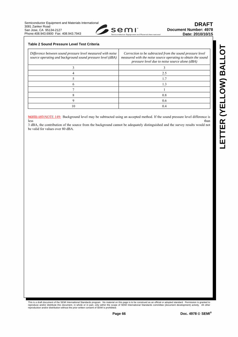
This is a draft document of the SEMI International Standards program. No material on this page is to be construed as an official or adopted standard. Permission is granted to reproduce and/or distribute this document, in whole or in part, only within the scope of SEMI International Standards committee (document development) activity. All other reproduction and/or distribution without the prior written consent of SEMI is prohibited.
Page 66 Doc. 4978 © SEMI®
Semiconductor Equipment and Materials International 3081 Zanker Road San Jose, CA 95134-2127 Phone:408.943.6900 Fax: 408.943.7943
LETT
ER (Y
ELLO
W) B
ALL
OT
DRAFTDocument Number: 4978
Date: 2010/10/15
Table 2 Sound Pressure Level Test Criteria
NOTE 157:NOTE 149: Background level may be subtracted using an accepted method. If the sound pressure level difference is less than 3 dBA, the contribution of the source from the background cannot be adequately distinguished and the survey results would not be valid for values over 80 dBA.
Difference between sound pressure level measured with noise source operating and background sound pressure level (dBA)
Correction to be subtracted from the sound pressure level measured with the noise source operating to obtain the sound
pressure level due to noise source alone (dBA)
3 3 4 2.5 5 1.7 6 1.3 7 1 8 0.8 9 0.6
10 0.4

This is a draft document of the SEMI International Standards program. No material on this page is to be construed as an official or adopted standard. Permission is granted to reproduce and/or distribute this document, in whole or in part, only within the scope of SEMI International Standards committee (document development) activity. All other reproduction and/or distribution without the prior written consent of SEMI is prohibited.
Page 67 Doc. 4978 © SEMI®
Semiconductor Equipment and Materials International 3081 Zanker Road San Jose, CA 95134-2127 Phone:408.943.6900 Fax: 408.943.7943
LETT
ER (Y
ELLO
W) B
ALL
OT
DRAFTDocument Number: 4978
Date: 2010/10/15
APPENDIX 1 INTEGRATION ISSUES FOR FPDMS
NOTICE: The material in this appendix is an official part of SEMI S26 and was approved by full letter ballot procedures on December 20, 2007 by the global Environmental, Health & Safety Committee.
NOTE 160: Criteria in this appendix are original to this safety guideline and are not found in SEMI S2-0706E. Therefore, text original to this safety guideline is NOT underlined in this appendix.
A1-1 General
A1-1.1 FPDMS consists of multiple subsystems (e.g., several pieces of equipment plus an AMHS) connected to each other. This has the possibility that hazards can migrate from one subsystem to the other. To ensure that these hazards are well addressed, the system integrator should request each supplier to indicate all integration requirements with adjacent subsystems.
A1-1.2 Communication of Hazards — Documentation should be provided that describes hazards that can be transferred to the adjacent subsystem. The system integrator of the FPDMS should verify that all risks associated with those hazards are mitigated to an acceptable level.
A1-2 Possible Integration Issues
A1-2.1 To mitigate safety risks, integration of safety-related systems as follows is often necessary and beneficial.
• Integration of EMO
• Integration of Stop switches
• Maintenance access issues
• Operator control
• Interlock integration
• Light tower requirements
• Other alarm or safety systems
A1-2.2 Integration of EMO — See § 12.
A1-2.3 Integration of Stop Switches — Where product flow has direct influence in more than one subsystem, activation of the machine stop at one of the subsystem should stop other subsystems.
EXAMPLE: Machine stop situation in a subsystem also requires that the delivery robot of the adjacent subsystem is stopped to prevent other hazardous situations.
A1-2.4 Maintenance Access Issues — When access to the operating envelope of the AMHS of a subsystem is needed for maintenance or service, the AMHS for the subsystem should be stopped using safety interlocks and HEI.
EXCEPTION: Access panels or doors that are labeled and require a tool to gain access do not require a safety interlock, but an HEI means and procedure should always be provided.
A1-2.5 Operator Control — Due to the size of the integrated FPDMS, there should be a location (central control) where the operator can control the entire FPDMS. The central control should be the sole control location for the entire FPDMS during normal operation. In case local control is needed, the central control should be disabled and indicate that the control is moved to local. This would require a handover protocol between the work stations.

This is a draft document of the SEMI International Standards program. No material on this page is to be construed as an official or adopted standard. Permission is granted to reproduce and/or distribute this document, in whole or in part, only within the scope of SEMI International Standards committee (document development) activity. All other reproduction and/or distribution without the prior written consent of SEMI is prohibited.
Page 68 Doc. 4978 © SEMI®
Semiconductor Equipment and Materials International 3081 Zanker Road San Jose, CA 95134-2127 Phone:408.943.6900 Fax: 408.943.7943
LETT
ER (Y
ELLO
W) B
ALL
OT
DRAFTDocument Number: 4978
Date: 2010/10/15
A1-2.6 Interlock Integration — Interlocks may need to be integrated to connect several safety systems and may require communication with more than two subsystems. An overview of integrated interlocks should be documented and provided to the user.
A1-2.7 Light Tower — All of Light Towers in an FPDMS should have same color designation through the system. The end-user should indicate if there is requirement for color designation by local code or user rule. Examples of color designation of the tower are:
• Red — Emergency situation, system malfunction
• Orange or Yellow — Operator attention needed
• Green — Normal situation
• Blue (optional) — System in Maintenance
• White (optional) — End-user to define or special indication needed (e.g., Laser active)
A1-2.8 Other Alarm or Safety Systems — Integration of safety systems belonging to different subsystems having similar functions may be necessary for the FPDMS. Integration of different types of safety systems and alarms may also be necessary for the FPDMS. Examples of safety systems and alarms to be considered for integration are:
• Fire detection
• Fire suppression
• Water-leak detection
• Machine stop
• Chemical detection

This is a draft document of the SEMI International Standards program. No material on this page is to be construed as an official or adopted standard. Permission is granted to reproduce and/or distribute this document, in whole or in part, only within the scope of SEMI International Standards committee (document development) activity. All other reproduction and/or distribution without the prior written consent of SEMI is prohibited.
Page 69 Doc. 4978 © SEMI®
Semiconductor Equipment and Materials International 3081 Zanker Road San Jose, CA 95134-2127 Phone:408.943.6900 Fax: 408.943.7943
LETT
ER (Y
ELLO
W) B
ALL
OT
DRAFTDocument Number: 4978
Date: 2010/10/15
APPENDIX 2 ENCLOSURE OPENINGS
NOTICE: The material in this appendix is an official part of SEMI S26 and was approved by full letter ballot procedures on December 20, 2007.
NOTE 161: All the contents in this appendix are originated in SEMI S2-0706E.
A2-1 Permissible Opening Sizes
A2-1.1 This appendix provides guidance on sizes of openings in enclosures.
Table A2-1 Examples of Openings for Protection Against Access from Operators
Distance Between Opening and Danger Point
Maximum Opening
mm inches mm inches
13 to 38 0.5 to 1.5 6 0.250 38 to 64 1.5 to 2.5 10 0.375 64 to 89 2.5 to 3.5 11.9 0.470 89 to 140 3.5 to 5.5 16 0.625
140 to 165 5.5 to 6.5 19 0.750 165 to 191 6.5 to 7.5 22 0.875
A2-1.2 Alternatively, an IEC accessibility probe, as specified in SEMI S22, Testing section, may be used to determine suitability of mesh openings.
A2-2 Top Openings in Electrical Enclosures — The top openings in electrical enclosures should meet one of the following:
• not exceed 5 mm in any dimension, or
• not exceed 1 mm in width regardless of length, or
• be so constructed that direct, vertical entry of a falling object is prevented from reaching un-insulated live parts within the enclosure by means of trap or restriction (see Figure A2-1 below for examples of top cover designs that prevent such direct entry), or
• meet the intent through other equivalent means.
SLANTED OPENINGS VERTICAL OPENINGS
Figure A2-1

This is a draft document of the SEMI International Standards program. No material on this page is to be construed as an official or adopted standard. Permission is granted to reproduce and/or distribute this document, in whole or in part, only within the scope of SEMI International Standards committee (document development) activity. All other reproduction and/or distribution without the prior written consent of SEMI is prohibited.
Page 70 Doc. 4978 © SEMI®
Semiconductor Equipment and Materials International 3081 Zanker Road San Jose, CA 95134-2127 Phone:408.943.6900 Fax: 408.943.7943
LETT
ER (Y
ELLO
W) B
ALL
OT
DRAFTDocument Number: 4978
Date: 2010/10/15
Line Item 4 – Revision to “Exhaust Ventilation”, Part B: Moving Appendix 3 to Relation Information 3 APPENDIX 3 DESIGN PRINCIPLES AND TEST METHODS FOR EVALUATING EXHAUST VENTILATION OF FPDMS OR SUBSYSTEM OF FPDMS — Design and Test Method Supplement Intended for Evaluating Party Use
NOTICE: The material in this appendix is an official part of SEMI S26 and was approved by full letter ballot procedures on December 20, 2007.
NOTE 162: Texts originated in SEMI S2-0706E and texts original to this appendix are differentiated by indicating the latter by underline.
A3-1 Introduction
A3-1.1 This appendix provides specific technical information relating to § 21. In general, it provides guidelines for:
•ventilation design for FPDMS or subsystem of FPDMS, and
•test validation criteria.
A3-1.2 This appendix is intended to be used as a starting point for reference during FPDMS’ subsystem design.
A3-1.3 This appendix is also intended to be used as reference for exhaust ventilation design consideration for integrated FPDMS.
A3-1.4 This appendix is not intended to limit hazard or test evaluation methods or control strategies (e.g., design principles) employed by manufacturers or users. Many different methods may be employed if they provide a sufficient level of protection.
A3-1.5 This appendix is not intended to provide exhaustive methods for determining final ventilation specifications. Other methods may be used where they provide at least equivalent sensitivity and accuracy.
A3-1.6 The exhaust velocities, volume flow rates and pressures listed are derived from a mixture of successful empirical testing and regulatory requirements.
A3-1.7 Test validation criteria are generally referenced from the applicable internationally recognized standard. It is the user’s responsibility to ensure that the most current revision of the standard is used.
Table A3-1 Ventilation
Hood Type Recommended Test Methods Typical Design and Test Exhaust Parameters #1
References
Wet Station Primary: aerosol visualization, air sampling Supplemental: Capture velocity, slot velocity, tracer gas, air sampling
0.28 to 0.50 m/s (55 to 100 fpm) capture velocity for non-heated 0.36 to 0.76 m/s (70 to 150 fpm) capture velocity for heated 120% to 125% of the laminar flow volume flow rate across the top of the deck
ACGIH Industrial Ventilation Manual SEMI S6

This is a draft document of the SEMI International Standards program. No material on this page is to be construed as an official or adopted standard. Permission is granted to reproduce and/or distribute this document, in whole or in part, only within the scope of SEMI International Standards committee (document development) activity. All other reproduction and/or distribution without the prior written consent of SEMI is prohibited.
Page 71 Doc. 4978 © SEMI®
Semiconductor Equipment and Materials International 3081 Zanker Road San Jose, CA 95134-2127 Phone:408.943.6900 Fax: 408.943.7943
LETT
ER (Y
ELLO
W) B
ALL
OT
DRAFTDocument Number: 4978
Date: 2010/10/15
Hood Type Recommended Test Methods Typical Design and Test Exhaust Parameters #1
References
Gas Cylinder Cabinets
Primary: face velocity, tracer gas Supplemental: aerosol visualization
1.0 to 1.3 m/s (200 to 250 fpm) face velocity
ACGIH Industrial Ventilation Manual SEMI S6
Gas Panel Enclosure of FPDMS or subsystem of FPDMS
Primary: tracer gas, static pressure Supplemental: aerosol visualization
4 to 5 air changes per minute −12.74 to −24.5 Pa [−1.3 to −2.5 mm (−0.05 to −0.1 in.) H2O] static pressure
ACGIH Industrial Ventilation Manual SEMI S6
Diffusion Furnace Scavenger
Primary: face velocity, aerosol visualization Supplemental: tracer gas, air sampling
0.50 to 0.76 m/s (100 to 150 fpm) face velocity NOTE: Do not use hot wire anemometer.
ACGIH Industrial Ventilation Manual SEMI S6
Chemical Dispensing Cabinets
Primary: static pressure Supplemental: aerosol visualization, air sampling where safe, tracer gas where emission rates can be accurately calculated
−12.74 to −24.5 Pa [−1.3 to −2.5 mm (−0.05 to −0.1 inch) H2O] static pressure 2 to 3 air changes per minute
ACGIH Industrial Ventilation Manual SEMI S6
Parts-Cleaning Hoods
Primary: face velocity, aerosol visualization Supplemental: tracer gas, air sampling
0.40 to 0.64 m/s (80 to 125 fpm) face velocity
ASHRAE Standard 110 SEMI S6 ACGIH Industrial Ventilation Manual
Pump and Exhaust Lines of FPDMS or subsystem of FPDMS
Primary: static pressure Supplemental: tracer gas
−58.8 to −245 Pa [−6 to −25 mm (−0.25 to −1.0 inch) H2O] static pressure 125% maximum volume flow rate from pump
ACGIH Industrial Ventilation Manual SEMI S6
Glove Boxes Primary: static pressure, tracer gas Supplemental: vapor visualization, air monitoring
No consensus for a reference at the time of publication of this guideline.
ACGIH Industrial Ventilation Manual SEMI S6
Drying/ Bake/ Test Chamber Ovens
Primary: static pressure, tracer gas Supplemental: vapor visualization, air monitoring
−12.74 to −24.5 Pa (−1.3 to −2.5 mm (−0.05 to −0.1 inch) H2O) static pressure
SEMI S6 ACGIH Industrial Ventilation Manual
Spin-Coater (cup only)
Primary: aerosol visualization, velometry Supplemental: air sampling
(see SEMI S26 ¶¶ 23.5.1–23.5.3) ACGIH Industrial Ventilation Manual
Supplemental Exhaust
Primary: capture velocity, aerosol visualization, air sampling
0.50 to 0.76 m/s (100 to 150 fpm) capture velocity
ACGIH Industrial Ventilation Manual
#1 All measurements should be within ±20% of average for face velocity, ±10% of average along the length of each slot for slot velocity, and ±10% of average between slots for slot velocity.
A3-2 Exhaust Optimization
A3-2.1 Exhaust optimization is the use of good ventilation design to create efficient FPDMS or subsystem of FPDMS exhaust. The design and measurement methods discussed below confirm that FPDMS or subsystem of FPDMS exhaust is acting as the manufacturer intended. This information is not meant to prohibit alternate methods of achieving or verifying good ventilation design. References for ventilation design are included at the end of this Appendix.
A3-2.2 Design Recommendations

This is a draft document of the SEMI International Standards program. No material on this page is to be construed as an official or adopted standard. Permission is granted to reproduce and/or distribute this document, in whole or in part, only within the scope of SEMI International Standards committee (document development) activity. All other reproduction and/or distribution without the prior written consent of SEMI is prohibited.
Page 72 Doc. 4978 © SEMI®
Semiconductor Equipment and Materials International 3081 Zanker Road San Jose, CA 95134-2127 Phone:408.943.6900 Fax: 408.943.7943
LETT
ER (Y
ELLO
W) B
ALL
OT
DRAFTDocument Number: 4978
Date: 2010/10/15
A3-2.2.1 Exhaust design of FPDMS or subsystem of FPDMS can attempt to reduce inefficient static pressure losses caused by: friction losses from materials; openings and duct geometries (elbows, duct expansions or contractions); turbulent air flow; fans; internal fittings such as blast gates and dampers; and directional changes in airflow.
A3-2.2.2 Other good design principles can include minimizing distance between the source and hood, and reducing enclosure volumes.
A3-2.2.3 For non-chemical issues such as heat from electrical parts of FPDMS or subsystem of FPDMS, heat recapture rather than exhaust may be appropriate.
A3-2.2.4 The possible impact of highly directional laminar airflow found in most facilities should be considered when designing exhaust of FPDMS or subsystem of FPDMS.
A3-2.3 Recommended Controls of FPDMS or Subsystem of FPDMS — The location of internal blast gates or dampers inside FPDMS or subsystem of FPDMS, and their appropriate settings, should be clearly identified. The number of dampers of FPDMS or subsystem of FPDMS and blast gates should be minimized. Gates/dampers should be lockable or otherwise securable. Static pressure or flow sensors installed on FPDMS or subsystem of FPDMS by the manufacturer should have sufficient sensitivity and accuracy to measure exhaust flowrate fluctuations that place the FPDMS or subsystem of the FPDMS out of prescribed ranges.
A3-2.4 Recommended Measurement/Validation Method — Measurements should be made to identify optimal exhaust levels and confirm that safety and process requirements are being addressed. The manufacturer should be able to identify any critical locations of FPDMS or subsystem of FPDMS for chemical capture, and quantify appropriate exhaust values. Multiple validation/measurement methods may be needed.
A3-2.4.1 Measurements should be done after components of the FPDMS or subsystem of the FPDMS are assembled.
A3-2.4.2 Computer modeling can be done to predict exhaust flow and hazardous material transportation in FPDMS or subsystem of FPDMS by solving fluid mechanics conservation of energy and mass equations. Modeling can be used in design of the FPDMS or subsystem of the FPDMS stage or to improve existing FPDMS or subsystem of FPDMS. Computer models should be verified experimentally, using one or more of the methods discussed below.
A3-2.4.3 Tracer gas testing provides a method to test the integrity of hoods by simulating gas emission and measuring the effectiveness of controls. Testing until there is a failure, and then slightly increasing the flow rate until the test is successful can be used to help minimize air flow specifications.
A3-2.4.4 Chemical air or wipe monitoring can be used to confirm that chemical transportation is not occurring into unintended areas of the FPDMS or subsystem of the FPDMS.
A3-2.4.5 Aerosol visualization will confirm expected airflows, the direction of flow, and the effect of distance. Aerosol visualization is the observation of aerosols (e.g., aerosols generated by using water, liquid nitrogen, or dry ice) so that exhaust flow patterns can be observed. Smoke tubes may also be used, however they can produce contamination.
A3-3 Chemical Laboratory Fume Hoods, Parts Cleaning Hoods
A3-3.1 Laboratory fume hoods and part cleaning hoods are designed to control emission by enclosing a process on five sides and containing the emission within the hood.
A3-3.2 Design Recommendations
A3-3.2.1 Fully enclosed on five sides, open on one side for employee access and process/parts placement and removals.
A3-3.2.2 Front (employee access side) should be provided with sliding door or sash.

This is a draft document of the SEMI International Standards program. No material on this page is to be construed as an official or adopted standard. Permission is granted to reproduce and/or distribute this document, in whole or in part, only within the scope of SEMI International Standards committee (document development) activity. All other reproduction and/or distribution without the prior written consent of SEMI is prohibited.
Page 73 Doc. 4978 © SEMI®
Semiconductor Equipment and Materials International 3081 Zanker Road San Jose, CA 95134-2127 Phone:408.943.6900 Fax: 408.943.7943
LETT
ER (Y
ELLO
W) B
ALL
OT
DRAFTDocument Number: 4978
Date: 2010/10/15
A3-3.2.3 Minimize size of the hood based on process size.
A3-3.2.4 Minimize front opening size based on size of process and employee access needs.
A3-3.2.5 Ensure hood construction materials are compatible with chemicals used.
A3-3.3 Control Specifications — Face velocity is the specification generally used with hoods open on only one side.
A3-3.3.1 Generally acceptable laboratory fume hood face velocities range from 0.40 to 0.60 m/s (80 to 120 fpm) with each single measurement within ±20 % of average. 0.64 to 0.76 m/s (125 to 150 fpm) is recommended for hoods in which carcinogens or reproductive toxicants may be used.
A3-3.3.2 Velocities as low as 0.30 to 0.40 m/s (60 to 80 fpm) can be effective but require no cross drafts or competing air movement in the work area.
A3-3.3.3 An average face velocity of 0.50 m/s (100 fpm) is generally found to be acceptable in most applications.
A3-3.3.4 Face velocities of 0.64 to 0.76 m/s (125 to 150 fpm) may be required when a lab hood is installed in an area with laminar air flow.
A3-3.3.5 Face velocity above 0.76 m/s (150 fpm) should be avoided to prevent eddying caused by a lower pressure area in front of an employee standing at the hood.
A3-3.4 Recommended Measurement/Validation Method
A3-3.4.1 The preferred method is measurement of average face velocity and hood static pressure. Measurements are taken with a velometer or anemometer. Multiple measurements are taken in a grid, at least 10 to 40 per square meter (1 to 4 per square foot) of open area, in the plane opening of the hood. This allows representative, evenly spaced measurements to be taken (see also open-surface tanks).
A3-3.4.2 Additional confirmations by visualization check of containment using smoke or aerosol testing.
A3-3.4.3 ASHRAE Method 110, or equivalent (use appropriate sections), for tracer gas testing of laboratory hoods may be used as a supplemental verification provided that an accurate emission rate can be defined. (ASHRAE 110 lists 3 tests: “as manufactured,” “as used,” and “as installed.” The “as manufactured” test is the test that is used most frequently.)
A3-4 Wet Stations
A3-4.1 Wet stations are slotted hoods designed to capture laminar air flow while also capturing wet process emissions from the work area. Wet stations can be open on the front, top and both sides. (It is usually preferable to enclose as much as possible.)
A3-4.2 Design Recommendations
A3-4.2.1 Slots should be provided uniformly along the length of the hood for even distribution of airflow.
A3-4.2.2 Additional lip exhaust slots should be provided around tanks or sinks to control emissions.
A3-4.2.3 The plenum behind the slots should be sized to ensure even distribution of static pressure. These slots should be designed to ensure adequate airflow is provided by the side slots, and to minimize turbulence that could reduce exhaust performance.
A3-4.2.4 Velocity along length of slot should not vary by more than 10% of the average slot velocity.

This is a draft document of the SEMI International Standards program. No material on this page is to be construed as an official or adopted standard. Permission is granted to reproduce and/or distribute this document, in whole or in part, only within the scope of SEMI International Standards committee (document development) activity. All other reproduction and/or distribution without the prior written consent of SEMI is prohibited.
Page 74 Doc. 4978 © SEMI®
Semiconductor Equipment and Materials International 3081 Zanker Road San Jose, CA 95134-2127 Phone:408.943.6900 Fax: 408.943.7943
LETT
ER (Y
ELLO
W) B
ALL
OT
DRAFTDocument Number: 4978
Date: 2010/10/15
A3-4.2.5 Additional use of end or side panels/baffles can reduce negative effect of side drafts.
A3-4.2.6 Exhaust volume settings should consider laminar air flow volumes and be balanced to minimize turbulence and to ensure capture.
A3-4.2.7 The station design should consider airflow patterns in the operating zone to minimize turbulent horizontal airflow patterns into and across the work deck.
A3-4.2.8 Additional considerations to reduce exhaust demand include providing covered tanks, and recessing tanks below deck level.
A3-4.3 Control Specifications
A3-4.3.1 Wet station specifications are complicated by the fact that wet stations generally do not have an easily definable face velocity to measure. A number of methods have been used and are all acceptable if used consistently and provided documentation indicates chemical containment meets the 1% of the OEL at distances beyond the plane of penetration at the exterior of the wet station.
A3-4.3.2 Maintain an average capture velocity of 0.33 to 0.50 m/s (65 to 100 fpm) immediately above a bath.
A3-4.3.3 Calculate the total exhaust volume requirement by determining the total volumetric flow of laminar air hitting the deck and increasing this value by 20% to 25%.
A3-4.4 A2-2.1.2 For some wet stations that are partially enclosed from the top, an artificial plane opening (“face”) can be defined where the downward laminar air flow penetrates the capture zone (at “face velocity”) of the wet station. Depending on the hood design and laminar air flow provided, average face velocities can range from 0.20 to 0.50 m/s (40 to 100 fpm). The measurement location can greatly influence the measured face velocity; therefore, this method should be supplemented with at least one of the preceding methods for greater accuracy and reproducibility at the user’s facility.
A3-4.4 Recommended Measurement/Validation Method
A3-4.4.1 Confirmation of captures using aerosol visualization.
A3-4.4.2 Confirmation of laminar flow of make up air into the station using aerosol visualization.
A3-4.4.3 Tracer gas testing may be used as supplemental verification, provided an emission rate can be accurately defined.
A3-5 Supplemental Exhaust
A3-5.1 Supplemental exhaust, if not designed into the FPDMS or subsystem of the FPDMS, can be provided by a flexible duct with a tapered hood. This can be placed in the work area to remove potential contaminants before they enter the breathing zone. Supplemental exhaust is frequently used during maintenance or service.
A3-5.2 Design Recommendations
A3-5.2.1 Retractable or movable non-combustible flexible ducting for easy reach and placement within 150 to 300 mm (6 to 12 inches) of potential emissions to be controlled.
A3-5.2.2 Manual damper at hood to allow for local control (i.e., shut off when not required).
A3-5.2.3 Tapered hood with a plane opening as a minimum. The additional use of flanges or canopies to enclose the process will result in improved efficiency.

This is a draft document of the SEMI International Standards program. No material on this page is to be construed as an official or adopted standard. Permission is granted to reproduce and/or distribute this document, in whole or in part, only within the scope of SEMI International Standards committee (document development) activity. All other reproduction and/or distribution without the prior written consent of SEMI is prohibited.
Page 75 Doc. 4978 © SEMI®
Semiconductor Equipment and Materials International 3081 Zanker Road San Jose, CA 95134-2127 Phone:408.943.6900 Fax: 408.943.7943
LETT
ER (Y
ELLO
W) B
ALL
OT
DRAFTDocument Number: 4978
Date: 2010/10/15
A3-5.3 Control Specifications
NOTE 163: This is one equation that is most commonly used. Other equations may be appropriate; see also ACGIH Industrial Ventilation Manual, and Semiconductor Exhaust Ventilation Guidebook.
A3-5.3.1 A minimum capture velocity of 0.50 m/s (100 fpm) is required at the contaminant generation point for releases of vapor via evaporation or passive diffusion. Ventilation should not be relied upon to prevent exposures to hazardous substances with release velocities (e.g., pressurized gases). For a plane open ended duct without a flange, the air flow required at a given capture velocity can be calculated by:
Q = V (10X2 + A) (A3-1)
where:
Q = required exhaust air flow in m3/s (cfm)
V = capture velocity in m/s (fpm) at distance X from hood
X = distance from hood face to farthest point of contaminant release in meters (feet)
A = hood face area in square meters (square feet)
NOTE 164: This is accurate only when X is within 1.5 diameters of a round opening, or within 0.25 circumference of a square opening.
A3-5.4 Recommended Measurement/Validation Method
A3-5.4.1 Measurement of capture velocity at farthest point of contaminant release. Measurements taken with a velometer or anemometer.
A3-5.4.2 Confirmation by visualization check of capture using aerosol capture testing.
A3-6 Gas Panel Enclosures of FPDMS or Subsystem of FPDMS
A3-6.1 Gas panel enclosures of FPDMS or subsystem of FPDMS, also known as gas boxes, jungle enclosures, gas jungle enclosures, valve manifold boxes, and secondary gas panel enclosures, are typically six-sided fully enclosed enclosures with access panels/doors on at least one side. These ventilated enclosures are designed to contain and remove hazardous gases from the work area in the event of a gas piping failure or leak. Gas panel enclosures are typically of two types, those requiring no access while gas systems are charged, and those that must be opened during processing while gas systems are charged. There is also a distinct difference in control specifications for those with pyrophorics or other flammables vs. other HPMs, specifically in the control of pocketing.Design Recommendations
A3-6.1.1 Compartmentalize potential leak points.
A3-6.1.2 Minimize the total size of the panel and its enclosure.
A3-6.1.3 Minimize size and number of openings.
A3-6.1.4 Minimize static pressure requirements of the enclosure; control has been shown to be achievable with −12.74 to −24.5 Pa [−1.3 to −2.5 mm (−0.05 to −0.1 in.) w.g.].
A3-6.1.5 Design for sweep. Minimize the number and size of openings. Seal unnecessary openings (e.g., seams, utility holes).
A3-6.1.6 Where routinely used access doors are required:
•Make the access door as small as practical.

This is a draft document of the SEMI International Standards program. No material on this page is to be construed as an official or adopted standard. Permission is granted to reproduce and/or distribute this document, in whole or in part, only within the scope of SEMI International Standards committee (document development) activity. All other reproduction and/or distribution without the prior written consent of SEMI is prohibited.
Page 76 Doc. 4978 © SEMI®
Semiconductor Equipment and Materials International 3081 Zanker Road San Jose, CA 95134-2127 Phone:408.943.6900 Fax: 408.943.7943
LETT
ER (Y
ELLO
W) B
ALL
OT
DRAFTDocument Number: 4978
Date: 2010/10/15
•Place the openings to the enclosure in the access door to minimize air flow requirements.
•Provide baffles behind the door to direct leaks away from the door and openings.
•Compartmentalize the enclosure so that access to one area does not affect air flow control in other areas.
A3-6.2 Control Specifications
A3-6.2.1 Exhaust volumes as low as 4 to 5 air changes per minute or less can be specified and meet the SEMI S26 criteria in § 23.5 if the design principles listed above are considered when designing of FPDMS or subsystem of FPDMS and enclosures.
A3-6.2.2 Where there is potential for chemical exposure during access, which can be controlled by face velocity, the enclosure should also provide a minimum face velocity of 0.36 to 0.76 m/s (70 to 150 fpm) when open. Face velocity should not be relied upon to control emissions from a pressurized fitting.
A3-6.2.3 Enclosures for pyrophoric or flammable gases should be designed to ensure adequately uniform dilution (i.e., prevent “pocketing”) and to prevent accumulation of pyrophoric and flammable gases above their lower flammable limit. Uniform dilution can generally be verified through exhaust aerosol visualization techniques. Ventilation flow rate should be adequate to maintain concentrations below 25% of the lower flammable limit for the gas with the lowest LFL that is used in the enclosure. This can generally be verified using engineering calculations to verify dilution, and aerosol visualization to verify mixing.
A3-6.3 Recommended Measurement/Validation Method
A3-6.3.1 Preferred validation by tracer gas testing per SEMI S6.
A3-6.3.2 Additional confirmation by visualization check of air flows, mixing and sweep using smoke or vapor testing.
A3-6.3.3 Measurement of average face velocity at inlet(s), opening(s), or routinely used access doors. Measurements should be taken with a velometer or anemometer. For larger openings, multiple measurements are taken in a grid, at least 10 to 40 per square meter (1 to 4 per square foot) of open area. Useful equation: V = 12.65 (VP/d)0.5, where V = velocity in m/s, VP = velocity pressure in Pa, and d = density correction factor (unitless). [V = 4.043 (VP/d)0.5, where V = velocity in m/s, VP = velocity pressure in mm H2O, and d = density correction factor (unitless)].
A3-7 Exhaust Ventilation Specifications and Measurements of FPDMS or Subsystem of FPDMS
A3-7.1 Exhaust specifications of FPDMS or subsystem of FPDMS should be provided by the supplier and define:
A3-7.1.1 The control specification or standard for the hood or enclosure (i.e., face velocity or capture velocity if applicable).
A3-7.1.2 The airflow in the duct required to maintain the control volume or flow required. Measurements should be made using the ACGIH Pitot traverse method described below.
A3-7.1.3 The location where the Pitot traverse measurement in the duct was made.
A3-7.1.4 Static pressure requirements.
A3-8 Duct Traverse Method
A3-8.1 Because the air flow in the cross-section of a duct is not uniform, it is necessary to obtain an average by measuring velocity pressure (VP) at points in a number of equal areas in the cross-section. The usual method is to make two traverses across the diameter of the duct at right angles to each other. Readings are taken at the center of

This is a draft document of the SEMI International Standards program. No material on this page is to be construed as an official or adopted standard. Permission is granted to reproduce and/or distribute this document, in whole or in part, only within the scope of SEMI International Standards committee (document development) activity. All other reproduction and/or distribution without the prior written consent of SEMI is prohibited.
Page 77 Doc. 4978 © SEMI®
Semiconductor Equipment and Materials International 3081 Zanker Road San Jose, CA 95134-2127 Phone:408.943.6900 Fax: 408.943.7943
LETT
ER (Y
ELLO
W) B
ALL
OT
DRAFTDocument Number: 4978
Date: 2010/10/15
annular rings of equal area. Whenever possible, the traverse should be made 7.5 duct diameters downstream and 3 diameters upstream from obstructions or directional changes such as an elbow, hood, or branch entry. Where measurements are made closer to disturbances, the results should be considered subject to some doubt and checked against a second location. If agreement within 10% of the two traverses is obtained, reasonable accuracy can be assumed and the average of the two readings used. Where the variation exceeds 10%, a third location should be selected and the two air flows in the best agreement averaged and used. The use of a single centerline reading for obtaining average velocity is a very coarse approximation and is not recommended. If a traverse cannot be done, then the centerline duct velocity should be multiplied by 0.9 for a coarse estimate of actual average duct velocity. Center line duct velocity should not be used less than 5 duct diameters from an elbow, junction, hood opening, or other source of turbulence.
A3-8.2 For ducts 150 mm (6 inches) and smaller, at least 6 traverse points should be used. For round ducts larger than 150 mm (6 inches) diameter, at least 10 traverse points should be employed. For very large ducts with wide variation in velocity, 20 traverse points will increase the precision of the air flow measurement.
A3-8.3 For square or rectangular ducts, the procedure is to divide the cross-section into a number of equal rectangular areas and measure the velocity pressure at the center of each. The number of readings should not be less than 16. Enough readings should be made so the greatest distance between centers is less than 150 mm (6 inches).
A3-8.4 The following data are required:
A3-8.4.1 The area of the duct at the traverse location.
A3-8.4.2 Velocity pressure at each point in the traverse or average velocity and number of points measured.
A3-8.4.3 Temperature of the air stream at the time and location of the traverse.
A3-8.4.4 The velocity pressure readings obtained are converted to velocities, and the velocities (not the velocity pressures) are averaged. Useful equation: V = 12.65 (VP/d)0.5, where V = velocity in m/s, VP = velocity pressure in Pa, and d = density correction factor (unitless) [V = 4.043 (VP/d)0.5, where V = velocity in m/s, VP = velocity pressure in mm H2O, and d = density correction factor (unitless)]. Some monitoring instruments conduct this averaging internal to the instrument.
A3-8.4.5 A2-2.1.3 Flow measurement taken at other than standard air temperatures should be corrected to standard conditions (i.e., 21°C (70°F), 0.1 MPa [760 mm (29.92 inches) Hg]).

This is a draft document of the SEMI International Standards program. No material on this page is to be construed as an official or adopted standard. Permission is granted to reproduce and/or distribute this document, in whole or in part, only within the scope of SEMI International Standards committee (document development) activity. All other reproduction and/or distribution without the prior written consent of SEMI is prohibited.
Page 78 Doc. 4978 © SEMI®
Semiconductor Equipment and Materials International 3081 Zanker Road San Jose, CA 95134-2127 Phone:408.943.6900 Fax: 408.943.7943
LETT
ER (Y
ELLO
W) B
ALL
OT
DRAFTDocument Number: 4978
Date: 2010/10/15
APPENDIX 4APPENDIX 3 DESIGN GUIDELINES FOR SUBSYSTEM OF FPDMS USING LIQUID CHEMICALS — Design and Test Method Supplement Intended for Evaluating Party Use
NOTICE: The material in this appendix is an official part of SEMI S26 and was approved by full letter ballot procedures on December 20, 2007.
NOTE 165: Texts originated in SEMI S2-0706E and texts original to this safety guideline are differentiated by indicating the latter by underline.
A4-1 A3-1 Introduction
A4-1.1 A3-1.1 This appendix provides specific technical information relating to § 23. In general, it provides information on hazards, recommended control methods, and design considerations.
A4-1.2 A3-1.2 This appendix is not intended to limit hazard evaluation methods or control strategies (e.g., design principles) employed by manufacturers. Alternative methods are acceptable if they provide an equivalent level of hazard control.
A4-1.3 A3-1.3 This appendix is intended to be used as a starting point for reference during design of the FPDMS’ subsystem. An example would be during a formal hazard analysis in a brainstorming session.
Table A4-1 Table A3-1 Liquid Chemicals
Hazard Recommended Control Method Design Considerations
Containment, control, and alarm notification for spills, leaks or vapors
Appropriately sized secondary containment (minimum 110% volume of entire contents) Exhaust of FPDMS’ subsystem Leak sensors to initiate auto shutdown
Controlled access to chemical containment areas
Door/access cover interlocks that automatically depressurize the area of FPDMS’ subsystem being accessed
Exposure to operators
Control of access to point-of-operation hazards
Physical guarding/presence-sensing devices
Control of chemical delivery pressure; control of residual chemicals
Depressurization upon FPDMS’ subsystem failure, interlock activation, or normal shutdown Transparent doors/covers allow visual inspection
Exposure to maintenance personnel
Serviceability Built-in system purge and flush capabilities System components accessible and easy to service
Chemical resistance/compatibility Appropriate materials used for construction of FPDMS’ subsystem and components
General FPDMS’ subsystem and component failure Pressure rating Pressurized systems designed to withstand 150% of maximum
foreseeable pressure, or provided with suitable relief valves Durable bulk chemical containers Use of approved (e.g., DOT, UN Dangerous Goods) containers in
bulk distribution systems Control of pressurized vessels and piping
Provide visual pressure indicators with or without alarms Pressurized vessels and piping are designed and built to recognized standards
Chemical delivery system leak
Spill control Automatic system pressure checks prior to allowing dispense Use of normally closed valves on distribution lines

This is a draft document of the SEMI International Standards program. No material on this page is to be construed as an official or adopted standard. Permission is granted to reproduce and/or distribute this document, in whole or in part, only within the scope of SEMI International Standards committee (document development) activity. All other reproduction and/or distribution without the prior written consent of SEMI is prohibited.
Page 79 Doc. 4978 © SEMI®
Semiconductor Equipment and Materials International 3081 Zanker Road San Jose, CA 95134-2127 Phone:408.943.6900 Fax: 408.943.7943
LETT
ER (Y
ELLO
W) B
ALL
OT
DRAFTDocument Number: 4978
Date: 2010/10/15
Hazard Recommended Control Method Design Considerations
Drum change-out controls Over-fill sensors on chemical baths Monitoring for excess flow Keyed and color-coded quick-connects
Control of ignition sources NFPA 70 (NEC) Class I, Division 2 wiring methods, intrinsically safe components, or nitrogen-purged enclosures Physical separation of ignition sources or potentially flammable atmospheres Use of low voltage to reduce the risk for ignition
Control of static electricity (i.e., one type of ignition source)
Maintain ground continuity
Heat/fire/chemical detection Limiting concentrations of fuels and oxidizers
Detection and interlocks as described in SEMI S6
Fire
Prevention of accumulation of flammable vapor
Ventilation to accomplish 25% LFL at every potential ignition source Vapor concentration monitoring interlocked with chemical and power supply

This is a draft document of the SEMI International Standards program. No material on this page is to be construed as an official or adopted standard. Permission is granted to reproduce and/or distribute this document, in whole or in part, only within the scope of SEMI International Standards committee (document development) activity. All other reproduction and/or distribution without the prior written consent of SEMI is prohibited.
Page 80 Doc. 4978 © SEMI®
Semiconductor Equipment and Materials International 3081 Zanker Road San Jose, CA 95134-2127 Phone:408.943.6900 Fax: 408.943.7943
LETT
ER (Y
ELLO
W) B
ALL
OT
DRAFTDocument Number: 4978
Date: 2010/10/15
APPENDIX 5APPENDIX 4 FIRE PROTECTION — Flowchart for Selecting Materials of Construction
NOTICE: The material in this appendix is an official part of SEMI S26 and was approved by full letter ballot procedures on December 20, 2007.
NOTE 166: Texts originated in SEMI S2-0706E and texts original to this safety guideline are differentiated by indicating the latter by underline.
Start
Can the subsystem of the FPDMS
reasonably be constructed of non-combustible
materials?
Does a qualified party (see ¶ 14.2.3) accept the risk
assessment and engineering controls?
Assess the fire risks based on the materials of construction and process chemicals.
Design engineering controls to mitigate the fire risks based on materials of construction and process chemicals. This may include fire detection and suppression systems.
Construct from non-combustible materials
Construct of materials which do not propagate flame*
Assess the fire risks based on the process chemicals.
Can the subsystem of the FPDMS
reasonably be constructed of materials which do not
propagate flame*?
Is there a significant fire risk, based on process
chemicals?
No
No
Yes
End
Yes
Yes
Yes
No
*beyond the ignition zone with or without the continued application of the ignition source
No
Figure A5-1Figure A4-1
Flowchart for Selecting Materials of Construction

This is a draft document of the SEMI International Standards program. No material on this page is to be construed as an official or adopted standard. Permission is granted to reproduce and/or distribute this document, in whole or in part, only within the scope of SEMI International Standards committee (document development) activity. All other reproduction and/or distribution without the prior written consent of SEMI is prohibited.
Page 81 Doc. 4978 © SEMI®
Semiconductor Equipment and Materials International 3081 Zanker Road San Jose, CA 95134-2127 Phone:408.943.6900 Fax: 408.943.7943
LETT
ER (Y
ELLO
W) B
ALL
OT
DRAFTDocument Number: 4978
Date: 2010/10/15
APPENDIX 6APPENDIX 5 IONIZING RADIATION TEST VALIDATION — Design and Test Method Supplement Intended for Evaluating Party Use
NOTICE: The material in this appendix is an official part of SEMI S26 and was approved by full letter ballot procedures on December 20, 2007.
NOTE 167: Texts originated in SEMI S2-0706E and texts original to this safety guideline are differentiated by indicating the latter by underline.
A6-1 A5-1 Introduction
A6-1.1 A5-1.1 This appendix provides specific technical information relating to § 24. In general, it provides information on hazard evaluation methods, examples of control strategies, and test validation criteria.
A6-1.2 A5-1.2 This appendix is not intended to limit hazard evaluation methods or control strategies (e.g., design principles) employed by the manufacturers. Alternative methods are acceptable if they provide an equivalent level of hazard control.
A6-1.3 A5-1.3 Test validation criteria are generally referenced from the applicable internationally recognized standard. It is the users responsibility to ensure that the most current revision of the standard (or its national equivalent) is used.
Table A6-1 Table A5-1 Ionizing Radiation
Ionizing Radiation Type
Emission Limit microsievert/hr (millirem/hr)
Test Method
X or Gamma Operator 2 μSv/hr
(0.2 mrem/hr)
Direct doserate measurement with an Ion Chamber (or equivalent) calibrated to ±10% of true doserate at the surface of the FPDMS’ subsystem (or at the closest approach) in all areas where the operator may have access with the ionizing radiation source active.
X or Gamma Maintenance and Service 10 μSv/hr
(1 mrem/hr)
Direct doserate measurement with an Ion Chamber (or equivalent) calibrated to ±10% of true doserate during simulated maintenance and service procedures. Measurements should be made at the surface emitting the ionizing radiation or the closest approach to the emitting surface with the ionizing radiation source active. NOTE: For these measurements, panels or shields should be removed only if removal is required for maintenance or service activities.
A6-2 A5-2 Basic Radiation Control Methods
A6-2.1 A5-2.1 Time — If the radiation field exists and it must be entered, then minimize the time spent in the field to minimize the exposure to the individual. This gives a linear dose reduction.
A6-2.2 A5-2.2 Distance — If the radiation field is present, stay as far away form the source as possible to perform the required tasks. Dose is reduced by the square of the distance from the source.
A6-2.3 A5-2.3 Shielding — If the radiation field is intense and the source is small, shielding the source is generally the most practical.
A6-2.4 A5-2.4 Quantity — If there exists an opportunity to minimize the amount of radiation or radioactive material that is required for the task, then the exposure can be minimized also.
This is a draft document of the SEMI International Standards program. No material on this page is to be construed as an official or adopted standard. Permission is granted to reproduce and/or distribute this document, in whole or in part, only within the scope of SEMI International Standards committee (document development) activity. All other reproduction and/or distribution without the prior written consent of SEMI is prohibited.
Page 82 Doc. 4978 © SEMI®
Semiconductor Equipment and Materials International 3081 Zanker Road San Jose, CA 95134-2127 Phone:408.943.6900 Fax: 408.943.7943
LETT
ER (Y
ELLO
W) B
ALL
OT
DRAFTDocument Number: 4978
Date: 2010/10/15
APPENDIX 7APPENDIX 6 NON-IONIZING RADIATION (OTHER THAN LASER) AND FIELDS TEST VALIDATION — Design and Test Method Supplement Intended for Evaluating Party Use, But Not for Field Survey of Installed Equipment
NOTICE: The material in this appendix is an official part of SEMI S26 and was approved by full letter ballot procedures on December 20, 2007.
NOTE 168: Texts originated in SEMI S2-0706E and texts original to this safety guideline are differentiated by indicating the latter by underline.
A7-1 A6-1 Introduction
A7-1.1 A6-1.1 This appendix provides specific technical information relating to § 25. In general, it provides information on hazard evaluation methods and test validation criteria.
A7-1.2 A6-1.2 This appendix is not intended to limit hazard evaluation methods or control strategies (e.g., design principles) employed by manufacturers. Alternative methods are acceptable if they provide an equivalent level of hazard control.
A7-1.3 A6-1.3 Test validation criteria are generally referenced from the applicable internationally recognized standards. It is the user’s responsibility to ensure that the most current revision of the standard is used.
A7-2 A6-2 Non-Ionizing Radiation Surveys should be conducted at the maximum operational power level and, when applicable, at the most limiting frequency.
A7-3 A6-3 Measurements should be taken at the exterior surfaces of the FPDMS’ subsystem and at surfaces that maintenance and repair personnel could encounter, whenever practical (electric field measurements with paddle-shaped sensors may not be possible in some places due to the size and shape of the sensor). Measurements for the purpose of evaluating emissions accessible to operators should be taken at the operators console and material loading station.
A7-4 A6-4 Measurements to assess electromagnetic emissions from the FPDMS’ subsystem for safety purposes should be taken in an area that is reasonably free of energy of the wavelengths/frequencies of interest, especially if the strength of the energy fluctuates in a manner that is unpredictable. Instruments used for safety-related measurements should be calibrated at a facility capable of calibrating such instruments using standards traceable to the National Institute of Standards and Technology in the USA or an equivalent standards service elsewhere, per the guidance of the instrument manufacturer. This should be determined by conducting surveys in the test area before the FPDMS’ subsystem is set up for the measurements. Measurements taken for safety purposes can also be combined with measurements taken to address electromagnetic interference concerns. The specific measurement locations may vary between electromagnetic interference and safety-related measurements.
NOTE 167:NOTE 150: The values in the table below are shown as 20% of the limit stated in the applicable standard (referenced).

This is a draft document of the SEMI International Standards program. No material on this page is to be construed as an official or adopted standard. Permission is granted to reproduce and/or distribute this document, in whole or in part, only within the scope of SEMI International Standards committee (document development) activity. All other reproduction and/or distribution without the prior written consent of SEMI is prohibited.
Page 83 Doc. 4978 © SEMI®
Semiconductor Equipment and Materials International 3081 Zanker Road San Jose, CA 95134-2127 Phone:408.943.6900 Fax: 408.943.7943
LETT
ER (Y
ELLO
W) B
ALL
OT
DRAFTDocument Number: 4978
Date: 2010/10/15
Table A7-1 Table A6-1 Non-Ionizing Radiation
Energy Category Physical Quantity
Measured(units)
Operator-Accessible Limit
Maintenance- and Service-Accessible
Limit
Pacemaker Labeling
Level
Testing Methods
Static 0 Hz. (e.g., static magnets in etch/implant equipment)
Magnetic Field Strength#1,2 (A/m or Gauss)
8 mT (80 G)
40 mT (400 G)
0.5 mT (5 G)
Use a Hall effect probe at each location (use three axis probe or make three mutually orthogonal measurements at each location). Measure field at exterior surfaces of the FPDMS’ subsystem (2 to 3 cm from the surface). Locate 5 gauss (G) line to post pacemaker warnings and 30 G to identify where flying tools, etc. and dislocations of magnetizable prostheses could become a hazard.
Sub Radio-frequency#1 1 Hz to 3 kHz (e.g., electro-magnets in etch equipment) *See exception below for 50 and 60 Hz power frequencies.
Electric Field Strength#1 (V/m)
1 to 100 Hz 5 kV/m*
100 Hz to 3 kHz 500,000/f (Hz)
in V/m
1 to 100 Hz 5 kV/m*
100 Hz to 3 kHz500,000/f (Hz)
in V/m
1 kV/m Use a displacement sensor. Determine the maximum field strength and orientation at the surface of the FPDMS’ subsystem (2 to 3 cm). Remove field perturbations by using a long non-conductive handle extension or remote fiber optic readout. Locate 1 kV/m line to post pacemaker warnings.
Sub Radio-frequency#1 1 Hz to 3 kHz (e.g., electro-magnets in etch equipment) *See exception below for 50 and 60 Hz power frequencies.
Magnetic Field Strength#1,2 (A/m or G)
1 to 300 Hz 12/f (Hz) in mT 300 Hz to 3 kHz
0.04 mT (400 mG)*
1 to 300 Hz 12/f (Hz) in mT 300 Hz to 3 kHz
0.04 mT (400 mG)*
0.1 mT (1 G)
Use a loop sensor at each location (use three axis probe or make three mutually orthogonal measurements at each location). The sensor should be almost contacting surface of the FPDMS’ subsystem (2 cm from surface). Identify 1 G line to post pacemaker warnings.
Power Frequency (50 or 60 Hz)#1
(e.g., electro-magnets in etch equipment)
Electric Field Strength#1 (V/m)
1 kV/m 2 kV/m 1 kV/m See Sub radiofrequency Electric Field Testing Method, but probe is positioned as needed to determine distance to 1 kV/m.
Power Frequency (50 or 60 Hz)#1
(e.g., electro-magnets in etch equipment)
Magnetic Field Strength#1,2 (A/m or G)
0.02 mT (200 mG)
0.1 mT (1 G)
0.1 mT (1 G)
See Sub radiofrequency Magnetic Field Testing Method, but probe is positioned as needed to determine distance to 1 G pacemaker criterion.

This is a draft document of the SEMI International Standards program. No material on this page is to be construed as an official or adopted standard. Permission is granted to reproduce and/or distribute this document, in whole or in part, only within the scope of SEMI International Standards committee (document development) activity. All other reproduction and/or distribution without the prior written consent of SEMI is prohibited.
Page 84 Doc. 4978 © SEMI®
Semiconductor Equipment and Materials International 3081 Zanker Road San Jose, CA 95134-2127 Phone:408.943.6900 Fax: 408.943.7943
LETT
ER (Y
ELLO
W) B
ALL
OT
DRAFTDocument Number: 4978
Date: 2010/10/15
Energy Category Physical Quantity
Measured(units)
Operator-Accessible Limit
Maintenance- and Service-Accessible
Limit
Pacemaker Labeling
Level
Testing Methods
Radio-frequency Field#2 3 kHz to 100 kHz (e.g., RF used to generate plasma)
Induced current and contact current (mA)
Frequency-dependent:
180f (kHz) in mA through both feet
90f through each foot
90f for contact. where f is in MHz
Frequency-dependent:
400f (kHz) in mA through both feet,
200f through each foot
200f for contact.where f is in MHz
NA Contact instrument vendor for suitable instrument based on frequency and emission characteristics. Measurement of induced and contact currents for freq. <100 MHz should be made when approaching 20% of the applicable electric field emission limit.
Radio-frequency Field#2 100 kHz to 100 MHz (e.g., RF used to generate plasma)
Induced current and contact current (mA)
18 mA through
both feet 9 mA through
each foot 9 mA contact
40 mA through
both feet 20 mA through
each foot 20 mA contact
NA Contact instrument vendor for suitable instrument based on frequency and emission characteristics. Measurement of induced and contact currents for freq. <100 MHz should be made when approaching 20% of the applicable electric field emission limit.
Radio-frequency Field#2 3 kHz to 300 MHz (e.g., RF used to generate plasma)
Electric Field Strength#1 (V/m)
Frequency dependent (see
ANSI/IEEE C95.1)20% of
Uncontrolled limit in Table 2 of C95.1
Frequency dependent (see
ANSI/IEEE C95.1)20% of Controlled limit in Table 1 of
C95.1
NA Use a diode rectifier or displacement sensor at each location (use three axis probe or make three mutually orthogonal measurements at each location). Measurements should be made at 20 cm from the surface.
Radio-frequency Field#2 3 kHz to 300 MHz (e.g., RF used to generate plasma)
Magnetic Field Strength#1,2 (A/m)
Frequency dependent (see
ANSI/IEEE C95.1)20% of
Uncontrolled limit in Table 2 of C95.1
Frequency dependent (see
ANSI/IEEE C95.1)20% of Controlled limit in Table 1 of
C95.1
NA Use a coil sensor at each location (use three axis probe or make three mutually orthogonal measurements at each location). Measurements should be made at 20 cm of the surface.
Radio-frequency Fields#2 300 MHz to 300 GHz (e.g., RF used to generate plasma)
Power Density#1 (mW/cm2)
Frequency dependent (see
ANSI/IEEE C95.1)20% of
Uncontrolled limit in Table 2 of C95.1
Frequency dependent (see
ANSI/IEEE C95.1)20% of Controlled limit in Table 1 of
C95.1
NA Use a diode rectifier or thermocouple at each location (use three axis probe or make three mutually orthogonal measurements at each location). Measurements should be made at 20 cm of the surface.
#1 It is assumed that electric and magnetic fields exist separately at frequencies below 300 MHz. It is assumed that electric and magnetic fields exist as a combined entity (electromagnetic radiation) at higher frequencies. Two evaluations are needed at frequencies <300 MHz and only one (usually made by measuring the electric field) at higher frequencies.
#2 1 gauss (G) ≈79.55 amperes per meter (A/m). 1 tesla (T) = 10,000 G, 1 millitesla (mT) = 10 G.

This is a draft document of the SEMI International Standards program. No material on this page is to be construed as an official or adopted standard. Permission is granted to reproduce and/or distribute this document, in whole or in part, only within the scope of SEMI International Standards committee (document development) activity. All other reproduction and/or distribution without the prior written consent of SEMI is prohibited.
Page 85 Doc. 4978 © SEMI®
Semiconductor Equipment and Materials International 3081 Zanker Road San Jose, CA 95134-2127 Phone:408.943.6900 Fax: 408.943.7943
LETT
ER (Y
ELLO
W) B
ALL
OT
DRAFTDocument Number: 4978
Date: 2010/10/15
Table A7-2 Table A6-2 Optical Energy
Optical Energy Physical Quantity Measured
(units)
Access Limit Testing Methods
Infrared Energy#1 700 nm to 1 mm (e.g., heating lamps)
Irradiance#1,2, 3 W/m2 Radiance W/m2 – sr
Wavelength dependent 20% of the applicable exposure limits. (See #1)
Thermocouple, thermopile, pyroelectric, photoelectric Direct measurements locating the maximum irradiance and orientation of the energy at the closest approach to the view port(s) or accessible leakage point(s).
Visible Light#1 400 nm to 700 nm (e.g., heating lamps)
Irradiance#1,2, 3 µW/cm2 Radiance W/m2 – sr
Wavelength dependent 20% of the applicable exposure limits. (See #1)
Thermocouple, thermopile, pyroelectric, photoelectric Direct measurement locating the maximum irradiance and orientation of the light energy at the closest approach to view port(s) or accessible leakage point(s).
Ultraviolet Energy#1 315 nm to 400 nm (e.g., plasma, stepper)
Irradiance#1,2 mW/cm2
0.2 mW/cm2 Photoelectric detectors with filters and or controlled phosphors Direct measurements locating the maximum irradiance and orientation of the energy at the closest approach to the view port(s) or accessible leakage point(s).
Ultraviolet Light#1 180 nm to 315 nm (e.g., plasma, stepper)
Effective Irradiance#4 µW/cm2
0.02 μW/ cm2 Photoelectric detectors with filters or controlled phosphors (See #5) Direct measurements locating the maximum irradiance and orientation of the energy at the closest approach to the view port(s) or accessible leakage point(s).
#1 “Irradiance” is essentially the same as “power density.”
#2 Lamp manufacturer data can sometimes be used to estimate and evaluate exposures using a spreadsheet.
#3 These guidelines cover visible, IR-A, and IR-B, and are frequency dependent. Separate evaluations may be needed for thermal or photochemical retinal hazards and infrared eye hazards.
#4 “Effective irradiance” is irradiance adjusted to account for the wavelength-dependent biological hazard. Permissible exposure time = 0.003 J/cm2 divided by the effective irradiance.
#5 Instrumentation is commercially available that accounts for the wavelength dependence of the standard and gives results in effective irradiance.
A7-5 A6-5 References
A7-5.1 A6-5.1 1996 TLVs and BEIs Threshold Limit Values for Chemical Substances and Physical Agents Biological Exposure Indices, ACGIH, Cincinnati, OH.
A7-5.2 A6-5.2 ANSI/IEEE Standard for Safety Levels with Respect to Human Exposure to Radio Frequency Electromagnetic Fields, 3 kHz to 300 GHz, C95.1-1991, Piscataway, New Jersey.
A7-5.3 A6-5.3 Guidelines on Limits of Exposure to Broad-Band Incoherent Optical Radiation (0.38 to 3 μM), Health Physics Vol. 73, No. 3 (September), pp.539–554, 1997.
A7-5.4 A6-5.4 ICNIRP 1994 “Guidelines on Limits of Exposure to Static Magnetic Fields,” Health Physics Vol. 66 (1) (January), pp. 100–106, 1994.
A7-5.5 A6-5.5 Interim Guidelines on the Limits of Exposure to 50/60 Hz Electric and Magnetic Fields, IRPA/ICNIRP Guidelines, Health Physics Vol. 58, No. 1 (January), pp. 113–122, 1990.

This is a draft document of the SEMI International Standards program. No material on this page is to be construed as an official or adopted standard. Permission is granted to reproduce and/or distribute this document, in whole or in part, only within the scope of SEMI International Standards committee (document development) activity. All other reproduction and/or distribution without the prior written consent of SEMI is prohibited.
Page 86 Doc. 4978 © SEMI®
Semiconductor Equipment and Materials International 3081 Zanker Road San Jose, CA 95134-2127 Phone:408.943.6900 Fax: 408.943.7943
LETT
ER (Y
ELLO
W) B
ALL
OT
DRAFTDocument Number: 4978
Date: 2010/10/15
APPENDIX 8APPENDIX 7 LASER DATA SHEET
NOTICE: The material in this appendix is an official part of SEMI S26 and was approved by full letter ballot procedures on December 20, 2007.
NOTE 170: All the contents in this appendix are originated from SEMI S2-0706E.
A8-1 A7-1 Equipment Information (All Laser Product Classes)
Laser Equipment Manufacturer ____________________________________________________
Equipment Model # ________________________
Date Laser Data Sheet Completed ________________
Laser Product Classification ______________ (e.g., 1, 1M, 2, 2M, 3A, 3R, 3B, 4)
Classification Standard(s) ______________ (e.g., IEC, FDA/CDRH, JIS)
Certification File Identification Number ______________ (e.g., CDRH accession number, or if CDRH accession number has been applied for, but not yet received, a statement of ‘pending’ along with the submittal date may be used instead). If self declaring under IEC 60825-1 or if certification is not required (e.g., if class 1 laser product is incorporated without changes, then ‘N/A’ may be used).
A8-2 A7-2 Laser Information (Greater than Class 2 & embedded Class 3R (3A), 3B & 4)
Is access to laser radiation above the maximum permissible exposure (MPE) level YES NO required during maintenance or service tasks? ____ _____
If NO, then the information in Parts A8A7-2, A8A7-3 and A8A7-4 need not be provided.
If YES, complete the information in Parts A8A7-2, A8A7-3 and A87A7-4 for each task and laser that requires access.
If there are multiple lasers contained within the laser equipment, provide the following for each task/laser combination that meets the above criteria.
Laser Parameters Laser ___1___, ___2___, __etc.__
Laser Manufacturer _______, _______, _______
Laser Model No. _______, _______, _______
A8-2.1 A7-2.1 Laser Medium Type (HeNe, Nd:YAG, Argon, KrF, Diode, etc.) _______, _______, _______
A8-2.2 A7-2.2 Wavelength(s) in nanometers (nm) _______, _______, _______
A8-2.3 A7-2.3 Laser Hazard Classification (individual laser) _______, _______, _______
NOTE 169:NOTE 151: If a laser is used in both continuous wave and pulsed modes, complete both § A8A7-2.4 and § A8A7-2.5.
A8-2.4 A7-2.4 Continuous Wave Lasers
A. Power in Watts (W) _______, _______, _______

This is a draft document of the SEMI International Standards program. No material on this page is to be construed as an official or adopted standard. Permission is granted to reproduce and/or distribute this document, in whole or in part, only within the scope of SEMI International Standards committee (document development) activity. All other reproduction and/or distribution without the prior written consent of SEMI is prohibited.
Page 87 Doc. 4978 © SEMI®
Semiconductor Equipment and Materials International 3081 Zanker Road San Jose, CA 95134-2127 Phone:408.943.6900 Fax: 408.943.7943
LETT
ER (Y
ELLO
W) B
ALL
OT
DRAFTDocument Number: 4978
Date: 2010/10/15
B. Irradiance in Watts/square centimeter (W/cm2 at aperture) _______, _______, _______
A8-2.5 A7-2.5 Pulsed Laser Characteristics
A. Pulse Duration in Seconds (s) _______, _______, _______
B. Energy per Pulse in Joules (J) _______, _______, _______
C. Pulse Repetition Frequency in Hertz (Hz) _______, _______, _______
D. Average Power in Watts (W) _______, _______, _______
E. Radiant Exposure Joules/square centimeter (J/cm2) _______, _______, _______
F. Q-Switch controlled pulses (Yes/No) _______, _______, _______
A8-2.6 A7-2.6 Beam Parameters at maintenance or service access points
EXCEPTION: In the case of proprietary information, an acceptable alternative to providing the Beam Parameters is to provide NOHD results for each access point according to IEC 60825 or equivalent.
A. Beam shape Circular (C), Rectangular (R), Elliptical (E) _______, _______, _______
B. Beam size (mm) Major axis (R/E) or diameter (C) _______, _______, _______
Minor axis (R/E) _______, _______, _______
Laser Parameters Laser ___1___, ___2___, __etc.__
C. Beam divergence in milliradians (mr)
Major axis (R/E) or diameter (C) _______, _______, _______
Minor axis (R/E) _______, _______, _______
D. Focal length in millimeters (mm) (of the emitting lens)
Major axis (R/E) or diameter (C) _______, _______, _______
Minor axis (R/E) _______, _______, _______
E. Is there a collecting optics hazard? (Yes/No) _______, _______, _______
A8-3 A7-3 Laser Control Measures
A8-3.1 A7-3.1 Specify maintenance/service tasks requiring access to laser radiation in excess of the MPE and recommended laser control measures.
A. Task 1 ________________________________________________________________
B. Task 2 ________________________________________________________________ C. Etc. ________________________________________________________________
NOTE 170:NOTE 152: Suppliers may alternately provide a reference to laser control measures information that is located in a document available to users.
A8-3.2 A7-3.2 Of the tasks in ¶ A8A7-3.1, which tasks need a Laser Controlled Area (for Class 3b or 4 lasers)?
_______________________________________________________________________________
A8-3.3 A7-3.3 If a nominal ocular hazard distance (NOHD) is used as a control measure, then provide the NOHD calculations and assumptions. See IEC 60825-1 for NOHD calculations.
EXCEPTION: If specific information required by § A8A7-2.6 is proprietary, suppliers may provide the NOHD results and an explanation of the assumptions made.

This is a draft document of the SEMI International Standards program. No material on this page is to be construed as an official or adopted standard. Permission is granted to reproduce and/or distribute this document, in whole or in part, only within the scope of SEMI International Standards committee (document development) activity. All other reproduction and/or distribution without the prior written consent of SEMI is prohibited.
Page 88 Doc. 4978 © SEMI®
Semiconductor Equipment and Materials International 3081 Zanker Road San Jose, CA 95134-2127 Phone:408.943.6900 Fax: 408.943.7943
LETT
ER (Y
ELLO
W) B
ALL
OT
DRAFTDocument Number: 4978
Date: 2010/10/15
A8-3.4 A7-3.4 Include a beam path diagram identifying the accessible points.
NOTE 171:NOTE 153: A description of the access points from the exterior of the tool can be considered equivalent to a diagram.
A8-4 A7-4 Personnel Protective Equipment (PPE)
A8-4.1 A7-4.1 Provide information for accessible laser radiation hazards in excess of the Maximum Permissible Exposure (MPE).
Laser Parameters Laser ___1___, ___2___, __etc.__
A. Optical Density (OD) of PPE required during maintenance _______, _______, _______
B. OD of PPE required during service activities _______, _______, _______
C. Other types of PPE (e.g., skin protection) if needed _______, _______, _______
NOTE 172:NOTE 154: Suppliers may alternately provide a reference to PPE information located in a document available to users.
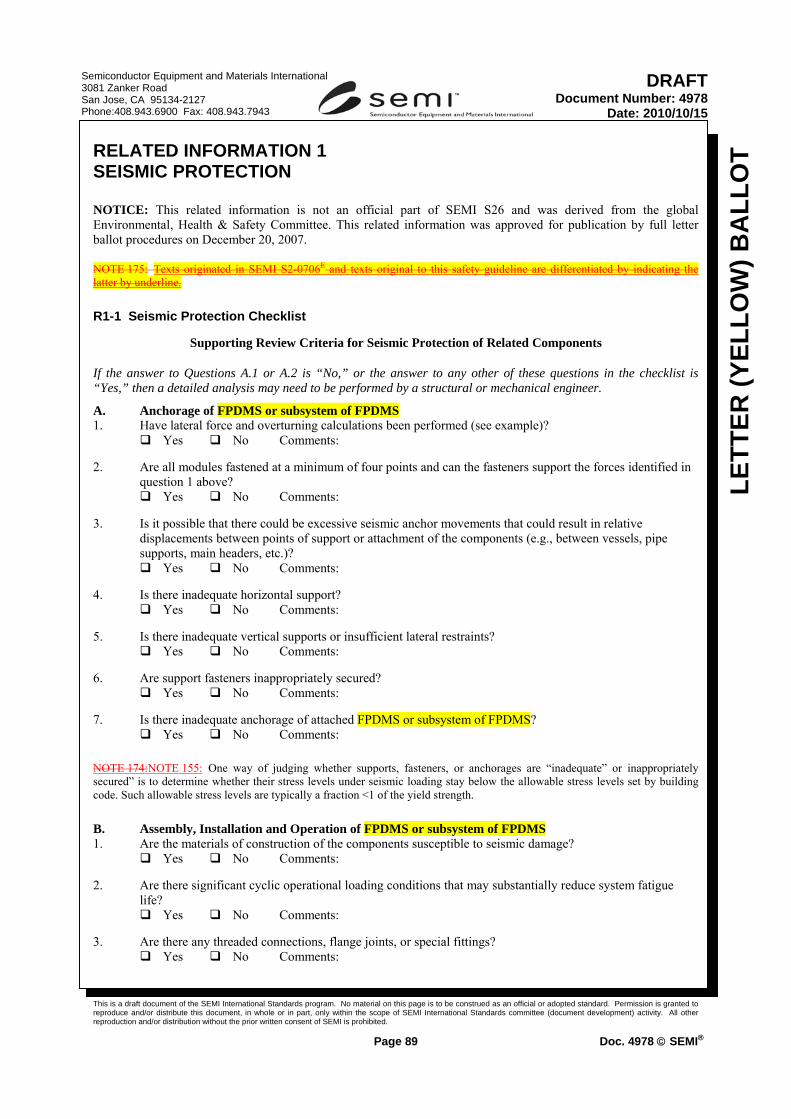
This is a draft document of the SEMI International Standards program. No material on this page is to be construed as an official or adopted standard. Permission is granted to reproduce and/or distribute this document, in whole or in part, only within the scope of SEMI International Standards committee (document development) activity. All other reproduction and/or distribution without the prior written consent of SEMI is prohibited.
Page 89 Doc. 4978 © SEMI®
Semiconductor Equipment and Materials International 3081 Zanker Road San Jose, CA 95134-2127 Phone:408.943.6900 Fax: 408.943.7943
LETT
ER (Y
ELLO
W) B
ALL
OT
DRAFTDocument Number: 4978
Date: 2010/10/15
RELATED INFORMATION 1 SEISMIC PROTECTION
NOTICE: This related information is not an official part of SEMI S26 and was derived from the global Environmental, Health & Safety Committee. This related information was approved for publication by full letter ballot procedures on December 20, 2007.
NOTE 175: Texts originated in SEMI S2-0706E and texts original to this safety guideline are differentiated by indicating the latter by underline.
R1-1 Seismic Protection Checklist
Supporting Review Criteria for Seismic Protection of Related Components
If the answer to Questions A.1 or A.2 is “No,” or the answer to any other of these questions in the checklist is “Yes,” then a detailed analysis may need to be performed by a structural or mechanical engineer.
A. Anchorage of FPDMS or subsystem of FPDMS 1. Have lateral force and overturning calculations been performed (see example)? Yes No Comments: 2. Are all modules fastened at a minimum of four points and can the fasteners support the forces identified in
question 1 above? Yes No Comments: 3. Is it possible that there could be excessive seismic anchor movements that could result in relative
displacements between points of support or attachment of the components (e.g., between vessels, pipe supports, main headers, etc.)?
Yes No Comments: 4. Is there inadequate horizontal support? Yes No Comments: 5. Is there inadequate vertical supports or insufficient lateral restraints? Yes No Comments: 6. Are support fasteners inappropriately secured? Yes No Comments: 7. Is there inadequate anchorage of attached FPDMS or subsystem of FPDMS? Yes No Comments:
NOTE 174:NOTE 155: One way of judging whether supports, fasteners, or anchorages are “inadequate” or inappropriately secured” is to determine whether their stress levels under seismic loading stay below the allowable stress levels set by building code. Such allowable stress levels are typically a fraction <1 of the yield strength.
B. Assembly, Installation and Operation of FPDMS or subsystem of FPDMS 1. Are the materials of construction of the components susceptible to seismic damage?
Yes No Comments: 2. Are there significant cyclic operational loading conditions that may substantially reduce system fatigue
life? Yes No Comments:
3. Are there any threaded connections, flange joints, or special fittings?
Yes No Comments:

This is a draft document of the SEMI International Standards program. No material on this page is to be construed as an official or adopted standard. Permission is granted to reproduce and/or distribute this document, in whole or in part, only within the scope of SEMI International Standards committee (document development) activity. All other reproduction and/or distribution without the prior written consent of SEMI is prohibited.
Page 90 Doc. 4978 © SEMI®
Semiconductor Equipment and Materials International 3081 Zanker Road San Jose, CA 95134-2127 Phone:408.943.6900 Fax: 408.943.7943
LETT
ER (Y
ELLO
W) B
ALL
OT
DRAFTDocument Number: 4978
Date: 2010/10/15
4. If answer to Question 4 is “Yes,” are these connections, joints, or special fittings in high stress locations? Yes No Comments:
5. Are there short or rigid spans that cannot accommodate the relative displacement of the supports (e.g.,
piping spanning between two structural systems)? Is hazardous gas piping provided with a “pigtail” (i.e., spiral) or bent 3 times (z, y, and z direction) to absorb 3-dimensional displacements?
Yes No Comments: 6. Are there large, unsupported masses (e.g., valves) attached to components?
Yes No Comments: 7. Are there any welded attachments to thin wall components?
Yes No Comments: 8. Could any sensitive equipment (e.g., control valves) be affected?
Yes No Comments: C. Seismic Interactions 1. Are there any points where seismically induced interaction with other elements, structures, systems, or
components could damage the components (e.g., impact, falling objects,)? Yes No Comments:
2. Could there be displacements from inertial effects?
Yes No Comments:
R1-2 Derivation of § 19, Seismic Load Guidelines
R1-2.1 The horizontal loadings of 94% and 63%, found in ¶ 19.2.1 and ¶ 19.2.2, were based on following assumptions for factors in formula 32-2 in § 1632.2 of the 1997 Uniform Building Code (UBC):
ap = 1.0 (i.e., treat the FPDMS or subsystem of FPDMS as a rigid structure)
Ca = 0.44(1.2) (i.e., seismic zone 4, soil profile type SD, and site 5 km from a seismic source type A)
Ip = 1.0 and 1.5 for non-HPM and HPM used in FPDMS or subsystem of FPDMS, respectively
hx/hr = 0.5 (i.e., FPDMS or subsystem of FPDMS attached at point halfway between grade elevation and roof elevation)
Rp = 1.5 (i.e., shallow anchor bolts)
Starting with equation 32-2, letting Ip = 1.5, and substituting the above values:
Fp (ultimate) = [(1.0 × 0.44(1.2) × 1.5)/1.5] [1 + 3(0.5)] Wp
= [0.44(1.2)] [1 + 1.5] Wp
= [0.528] [2.5] Wp
= [1.32] Wp
NOTE 175:NOTE 156: This number is now adjusted from ultimate strength loading to yield strength loading by dividing by 1.4:
Fp (yield) = Fp (ultimate)/1.4
= [1.32]/1.4 Wp
= [0.94] Wp

This is a draft document of the SEMI International Standards program. No material on this page is to be construed as an official or adopted standard. Permission is granted to reproduce and/or distribute this document, in whole or in part, only within the scope of SEMI International Standards committee (document development) activity. All other reproduction and/or distribution without the prior written consent of SEMI is prohibited.
Page 91 Doc. 4978 © SEMI®
Semiconductor Equipment and Materials International 3081 Zanker Road San Jose, CA 95134-2127 Phone:408.943.6900 Fax: 408.943.7943
LETT
ER (Y
ELLO
W) B
ALL
OT
DRAFTDocument Number: 4978
Date: 2010/10/15
And for Ip = 1.0,
Fp (yield) = [.94] [1.0/1.5] Wp
= [.63] Wp
Notes re-selection of ap value of 1.0:
Table 16-O of 1997 UBC, line 3.C., was interpreted to read: “Any flexible equipment...”
in structural terms, the structure of typical FPDMS or subsystem of FPDMS is considered “rigid.”
R1-2.2 Assumptions Used for Above Derivation
R1-2.2.1 Because typical FPDMS or subsystem of FPDMS is considered rigid, a frequency response analysis was not considered to be necessary.
R1-2.2.2 Seismic waves typically have vertical as well as horizontal components associated with them; however, these components typically arrive out of phase (i.e., they do not reach maximum values simultaneously). The vertical component serves to, in effect, reduce the amount of FPDMS or its subsystem mass that is available to resist overturning or toppling. The task force chose to take this into account by limiting the calculated weight available to resist overturning to 85% of the weight of the FPDMS or subsystem of the FPDMS. An alternate method, not chosen by the task force, could have been to simultaneously apply a vertical (Z) force.
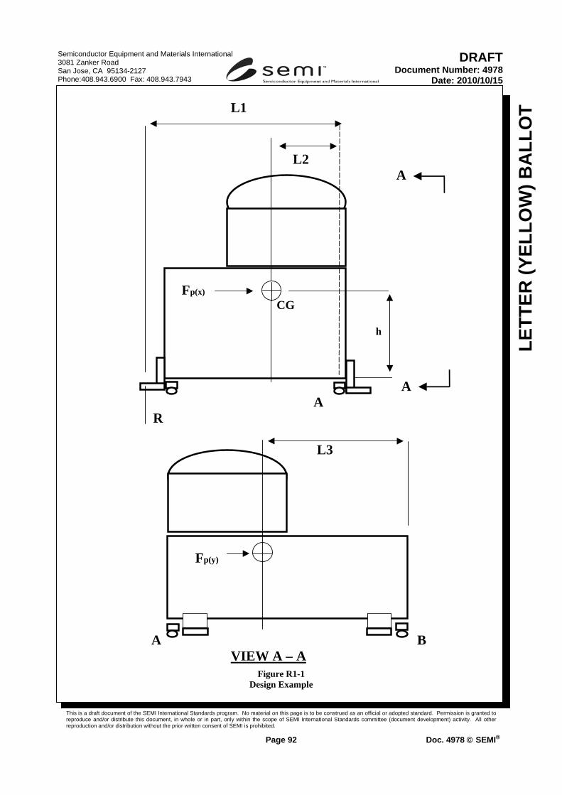
This is a draft document of the SEMI International Standards program. No material on this page is to be construed as an official or adopted standard. Permission is granted to reproduce and/or distribute this document, in whole or in part, only within the scope of SEMI International Standards committee (document development) activity. All other reproduction and/or distribution without the prior written consent of SEMI is prohibited.
Page 92 Doc. 4978 © SEMI®
Semiconductor Equipment and Materials International 3081 Zanker Road San Jose, CA 95134-2127 Phone:408.943.6900 Fax: 408.943.7943
LETT
ER (Y
ELLO
W) B
ALL
OT
DRAFTDocument Number: 4978
Date: 2010/10/15
L1
L2 A
h
A A
R
L3
A B VIEW A – A
Fp(x)
CG
Fp(y)
Figure R1-1
Design Example

This is a draft document of the SEMI International Standards program. No material on this page is to be construed as an official or adopted standard. Permission is granted to reproduce and/or distribute this document, in whole or in part, only within the scope of SEMI International Standards committee (document development) activity. All other reproduction and/or distribution without the prior written consent of SEMI is prohibited.
Page 93 Doc. 4978 © SEMI®
Semiconductor Equipment and Materials International 3081 Zanker Road San Jose, CA 95134-2127 Phone:408.943.6900 Fax: 408.943.7943
LETT
ER (Y
ELLO
W) B
ALL
OT
DRAFTDocument Number: 4978
Date: 2010/10/15
DESIGN EXAMPLE (continued; refer to Figure R1-1 for illustration of example):
Disclaimer: the calculations below are not a complete seismic analysis. A complete analysis might also include such things as: stress distribution through a multiple-fastener connection; prying action; bearing stress; simultaneous combined stresses on the fasteners; and a review of weld geometry. A complete seismic analysis should be done by a qualified engineer.
R1-3 Calculation of Lateral Force
R1-3.1 Lateral force on each leg is equal to FP/# of legs = FP/4
R1-3.2 The lateral force acts as shear on the floor anchor fasteners and shear or tensile loading on the FPDMS or its subsystem anchor fasteners depending upon orientation. The actual reactions of the fasteners should be calculated by a qualified engineer.
R1-4 Calculation of Overturning Force
R1-4.1 Sum the moments of the reactions on the FPDMS or subsystem of the FPDMS about line through the legs A and B:
(CW =+) ∑MAB= 0 = FP (h) − 0.85WP(L2) −2R(L1 )= 0 (R1-1)
FP (h) − 0.85WP(L2)
R = _________________ (R1-2) 2L1
FP = 0.94WP
WP (0.94h − 0.85L2) R = _________________ (R1-3)
2L1
If 0.94h ≥ 0.85L2, then there is a tension reaction, R, at the two anchors, to resist overturning of FPDMS or subsystem of FPDMS.
Example:
L1 = 50 inch
L2 = 20 inch
h= 36
W = 5000 lbs
Lateral force = Fp/4 = 0.94(5000)/4 = 1175
WP (0.94h − 0.85L2)
Overturning force = R =_________________ (R1-4) 2L1
= 5000 (0.94(36) − 0.85(20)) _____________________ (R1-5)

This is a draft document of the SEMI International Standards program. No material on this page is to be construed as an official or adopted standard. Permission is granted to reproduce and/or distribute this document, in whole or in part, only within the scope of SEMI International Standards committee (document development) activity. All other reproduction and/or distribution without the prior written consent of SEMI is prohibited.
Page 94 Doc. 4978 © SEMI®
Semiconductor Equipment and Materials International 3081 Zanker Road San Jose, CA 95134-2127 Phone:408.943.6900 Fax: 408.943.7943
LETT
ER (Y
ELLO
W) B
ALL
OT
DRAFTDocument Number: 4978
Date: 2010/10/15
2(50)
R = 842 lbs

This is a draft document of the SEMI International Standards program. No material on this page is to be construed as an official or adopted standard. Permission is granted to reproduce and/or distribute this document, in whole or in part, only within the scope of SEMI International Standards committee (document development) activity. All other reproduction and/or distribution without the prior written consent of SEMI is prohibited.
Page 95 Doc. 4978 © SEMI®
Semiconductor Equipment and Materials International 3081 Zanker Road San Jose, CA 95134-2127 Phone:408.943.6900 Fax: 408.943.7943
LETT
ER (Y
ELLO
W) B
ALL
OT
DRAFTDocument Number: 4978
Date: 2010/10/15
RELATED INFORMATION 2 EARTH LEAKAGE BREAKER/GROUND FAULT CIRCUIT INTERRUPTER, GROUND FAULT EQUIPMENT PROTECTION CIRCUIT INTERRUPTER, AND RESIDUAL CURRENT DEVICES
NOTICE: This related information is not an official part of SEMI S26 and was derived from the global Environmental, Health & Safety Committee. This related information was approved for publication by full letter ballot procedures on December 20, 2007.
NOTE 178: Criteria in this related information are original to this safety guideline and are not found in SEMI S2-0706E. Therefore, text original to this safety guideline is NOT underlined in this related information.
NOTE 157:Criteria for “the system” in this related information typically apply to each subsystem of an FPDMS that has a separate main electrical power feed. If an FPDMS receives all of its electricity from one main electrical power disconnect, “the system” should mean “the FPDMS.”
R2-1 Japanese regulations may require the use of Ground Fault Circuit Interrupter (GFCI), Ground Fault Equipment Protection Circuit Interrupter (GFEPCI), Residual Current Devices (RCD), or Earth Leakage Breaker (ELB) with the system.
EXCEPTION 1: The rating of the system is less than 20 amperes and less than 150 volts rms.
EXCEPTION 2: The system is supplied from the ungrounded secondary of an AC mains isolation transformer.
R2-2 The GFCI, GFEPCI, RCD or ELB, when required to satisfy Japanese requirements, should have trip ratings of not greater than 30 mA and 0.1 second.
EXCEPTION 1: If there is no accessible live circuit during maintenance tasks, trip ratings of up to 300 mA are acceptable.
EXCEPTION 2: If there is no accessible live circuit during maintenance tasks and the earth impedance is less than 50 ohms, a GFCI, GFEPCI, RCD or ELB of 500 mA maximum is acceptable.
EXCEPTION 3: If the system is connected to a source of supply that is provided with a GFCI, GFEPCI, RCD or ELB, an additional GFCI, GFEPCI, RCD or ELB is not required for the system.

This is a draft document of the SEMI International Standards program. No material on this page is to be construed as an official or adopted standard. Permission is granted to reproduce and/or distribute this document, in whole or in part, only within the scope of SEMI International Standards committee (document development) activity. All other reproduction and/or distribution without the prior written consent of SEMI is prohibited.
Page 96 Doc. 4978 © SEMI®
Semiconductor Equipment and Materials International 3081 Zanker Road San Jose, CA 95134-2127 Phone:408.943.6900 Fax: 408.943.7943
LETT
ER (Y
ELLO
W) B
ALL
OT
DRAFTDocument Number: 4978
Date: 2010/10/15
Line Item 4 – Revision to “Exhaust Ventilation”, Part B: Moving Appendix 3 to Relation Information 3 RELATED INFORMATION 3 DESIGN PRINCIPLES AND TEST METHODS FOR EVALUATING EXHAUST VENTILATION OF FPDMS OR SUBSYSTEM OF FPDMS — Design and Test Method Supplement Intended for Internal and Third Party Evaluation Use
NOTICE: This related information is not an official part of SEMI S26 and was derived from the global Environmental, Health & Safety Committee. This related information was approved for publication by full letter ballot procedures on December 20, 2007.
R3-1 Introduction
R3-1.1 This related information provides specific technical information relating to § 21. In general, it provides guidelines for:
• ventilation design for FPDMS or subsystem of FPDMS, and
• test validation criteria.
R3-1.2 This related information is intended to be used as a starting point for reference during FPDMS’ subsystem design.
R3-1.3 This related information is also intended to be used as reference for exhaust ventilation design consideration for integrated FPDMS.
R3-1.4 This related information is not intended to limit hazard or test evaluation methods or control strategies (e.g., design principles) employed by manufacturers or users. Many different methods may be employed if they provide a sufficient level of protection.
R3-1.5 This related information is not intended to provide exhaustive methods for determining final ventilation specifications. Other methods may be used where they provide at least equivalent sensitivity and accuracy.
R3-1.6 The exhaust velocities, volume flow rates and pressures listed are derived from a mixture of successful empirical testing and regulatory requirements.
R3-1.7 Test validation criteria are generally referenced from the applicable internationally recognized standard. It is the user’s responsibility to ensure that the most current revision of the standard is used.
Table R3-1 Ventilation
Hood Type Recommended Test Methods Typical Design and Test Exhaust Parameters #1
References
Wet Station Primary: aerosol visualization, air sampling Supplemental: Capture velocity, slot velocity, tracer gas, air sampling
0.28 to 0.50 m/s (55 to 100 fpm) capture velocity for non-heated 0.36 to 0.76 m/s (70 to 150 fpm) capture velocity for heated 110% to 125% of the laminar flow volume flow rate across the top of the deck
ACGIH Industrial Ventilation Manual Appendix 2 of SEMI S6

This is a draft document of the SEMI International Standards program. No material on this page is to be construed as an official or adopted standard. Permission is granted to reproduce and/or distribute this document, in whole or in part, only within the scope of SEMI International Standards committee (document development) activity. All other reproduction and/or distribution without the prior written consent of SEMI is prohibited.
Page 97 Doc. 4978 © SEMI®
Semiconductor Equipment and Materials International 3081 Zanker Road San Jose, CA 95134-2127 Phone:408.943.6900 Fax: 408.943.7943
LETT
ER (Y
ELLO
W) B
ALL
OT
DRAFTDocument Number: 4978
Date: 2010/10/15
Hood Type Recommended Test Methods Typical Design and Test Exhaust Parameters #1
References
Gas Cylinder Cabinets
Primary: face velocity, tracer gas Supplemental: aerosol visualization
1.0 to 1.3 m/s (200 to 250 fpm) face velocity
ACGIH Industrial Ventilation Manual Appendix 2 of SEMI S6
Gas Panel Enclosure of FPDMS or subsystem of FPDMS
Primary: tracer gas, static pressure Supplemental: aerosol visualization
4 to 5 air changes per minute −12.74 to −24.5 Pa [−1.3 to −2.5 mm (−0.05 to −0.1 in.) H2O] static pressure
ACGIH Industrial Ventilation Manual Appendix 2 of SEMI S6
Diffusion Furnace Scavenger
Primary: face velocity, aerosol visualization Supplemental: tracer gas, air sampling
0.50 to 0.76 m/s (100 to 150 fpm) face velocity NOTE: Do not use hot wire anemometer.
ACGIH Industrial Ventilation Manual Appendix 2 of SEMI S6
Chemical Dispensing Cabinets
Primary: static pressure Supplemental: aerosol visualization, air sampling where safe, tracer gas where emission rates can be accurately calculated
−12.74 to −24.5 Pa [−1.3 to −2.5 mm (−0.05 to −0.1 inch) H2O] static pressure 2 to 3 air changes per minute
ACGIH Industrial Ventilation Manual Appendix 2 of SEMI S6
Parts-Cleaning Hoods
Primary: face velocity, aerosol visualization Supplemental: tracer gas, air sampling
0.40 to 0.64 m/s (80 to 125 fpm) face velocity
ASHRAE Standard 110 Appendix 2 of SEMI S6 ACGIH Industrial Ventilation Manual
Pump and Exhaust Lines of FPDMS or subsystem of FPDMS
Primary: static pressure Supplemental: tracer gas
−58.8 to −245 Pa [−6 to −25 mm (−0.25 to −1.0 inch) H2O] static pressure 125% maximum volume flow rate from pump
ACGIH Industrial Ventilation Manual Appendix 2 of SEMI S6
Glove Boxes Primary: static pressure, tracer gas Supplemental: vapor visualization, air monitoring
No consensus for a reference at the time of publication of this guideline.
ACGIH Industrial Ventilation Manual Appendix 2 of SEMI S6
Drying/ Bake/ Test Chamber Ovens
Primary: static pressure, tracer gas Supplemental: vapor visualization, air monitoring
−12.74 to −24.5 Pa (−1.3 to −2.5 mm (−0.05 to −0.1 inch) H2O) static pressure
Appendix 2 of SEMI S6 ACGIH Industrial Ventilation Manual
Spin-Coater (cup only)
Primary: aerosol visualization, velometry Supplemental: air sampling
(see SEMI S26 ¶¶ 23.5.1–23.5.3) ACGIH Industrial Ventilation Manual
Supplemental Exhaust
Primary: capture velocity, aerosol visualization, air sampling
0.50 to 0.76 m/s (100 to 150 fpm) capture velocity
ACGIH Industrial Ventilation Manual
♯1 All measurements should be within ±20% of average for face velocity, ±10% of average along the length of each slot for slot velocity, and ±10% of average between slots for slot velocity.
R3-2 Exhaust Optimization
R3-2.1 Exhaust optimization is the use of good ventilation design to create efficient FPDMS or subsystem of FPDMS exhaust. The design and measurement methods discussed below confirm that FPDMS or subsystem of FPDMS exhaust is acting as the manufacturer intended. This information is not meant to prohibit alternate methods of achieving or verifying good ventilation design. References for ventilation design are included at the end of this related information.
R3-2.2 Design Recommendations

This is a draft document of the SEMI International Standards program. No material on this page is to be construed as an official or adopted standard. Permission is granted to reproduce and/or distribute this document, in whole or in part, only within the scope of SEMI International Standards committee (document development) activity. All other reproduction and/or distribution without the prior written consent of SEMI is prohibited.
Page 98 Doc. 4978 © SEMI®
Semiconductor Equipment and Materials International 3081 Zanker Road San Jose, CA 95134-2127 Phone:408.943.6900 Fax: 408.943.7943
LETT
ER (Y
ELLO
W) B
ALL
OT
DRAFTDocument Number: 4978
Date: 2010/10/15
R3-2.2.1 Exhaust design of FPDMS or subsystem of FPDMS can attempt to reduce inefficient static pressure losses caused by: friction losses from materials; openings and duct geometries (elbows, duct expansions or contractions); turbulent air flow; fans; internal fittings such as blast gates and dampers; and directional changes in airflow.
R3-2.2.2 Other good design principles can include minimizing distance between the source and hood, and reducing enclosure volumes.
R3-2.2.3 For non-chemical issues such as heat from electrical parts of FPDMS or subsystem of FPDMS, heat recapture rather than exhaust may be appropriate.
R3-2.2.4 The possible impact of highly directional laminar airflow found in most facilities should be considered when designing exhaust of FPDMS or subsystem of FPDMS.
R3-2.3 Recommended Controls of FPDMS or Subsystem of FPDMS — The location of internal blast gates or dampers inside FPDMS or subsystem of FPDMS, and their appropriate settings, should be clearly identified. The number of dampers of FPDMS or subsystem of FPDMS and blast gates should be minimized. Gates/dampers should be lockable or otherwise securable. Static pressure or flow sensors installed on FPDMS or subsystem of FPDMS by the manufacturer should have sufficient sensitivity and accuracy to measure exhaust flowrate fluctuations that place the FPDMS or the subsystem of the FPDMS out of prescribed ranges.
R3-2.4 Recommended Measurement/Validation Method — Measurements should be made to identify optimal exhaust levels and confirm that safety and process requirements are being addressed. The manufacturer should be able to identify any critical locations of FPDMS or subsystem of FPDMS for chemical capture, and quantify appropriate exhaust values. Multiple validation/measurement methods may be needed.
R3-2.4.1 Measurements should be done after components of the FPDMS or subsystem of the FPDMS are assembled.
R3-2.4.2 Computer modeling can be done to predict exhaust flow and hazardous material transportation in FPDMS or subsystem of FPDMS by solving fluid mechanics conservation of energy and mass equations. Modeling can be used in design of the FPDMS or the subsystem of the FPDMS stage or to improve existing FPDMS or subsystem of FPDMS. Computer models should be verified experimentally, using one or more of the methods discussed below.
R3-2.4.3 Tracer gas testing provides a method to test the integrity of hoods by simulating gas emission and measuring the effectiveness of controls. Testing until there is a failure, and then slightly increasing the flow rate until the test is successful can be used to help minimize air flow specifications.
R3-2.4.4 Chemical air or wipe monitoring can be used to confirm that chemical transportation is not occurring into unintended areas of the FPDMS or the subsystem of the FPDMS.
R3-2.4.5 Vapor visualization will confirm expected airflows, the direction of flow, and the effect of distance. Vapor visualization is the observation of aerosols (e.g., aerosols generated by using water, liquid nitrogen, or dry ice) so that exhaust flow patterns can be observed. Smoke tubes may also be used, however they can produce contamination.
R3-3 Chemical Laboratory Fume Hoods, Parts Cleaning Hoods
R3-3.1 Laboratory fume hoods and part cleaning hoods are designed to control emission by enclosing a process on five sides and containing the emission within the hood.
R3-3.2 Design Recommendations
R3-3.2.1 Fully enclosed on five sides, open on one side for employee access and process/parts placement and removals.
R3-3.2.2 Front (employee access side) should be provided with sliding door or sash.
This is a draft document of the SEMI International Standards program. No material on this page is to be construed as an official or adopted standard. Permission is granted to reproduce and/or distribute this document, in whole or in part, only within the scope of SEMI International Standards committee (document development) activity. All other reproduction and/or distribution without the prior written consent of SEMI is prohibited.
Page 99 Doc. 4978 © SEMI®
Semiconductor Equipment and Materials International 3081 Zanker Road San Jose, CA 95134-2127 Phone:408.943.6900 Fax: 408.943.7943
LETT
ER (Y
ELLO
W) B
ALL
OT
DRAFTDocument Number: 4978
Date: 2010/10/15
R3-3.2.3 Minimize size of the hood based on process size.
R3-3.2.4 Minimize front opening size based on size of process and employee access needs.
R3-3.2.5 Ensure hood construction materials are compatible with chemicals used.
R3-3.3 Control Specifications — Face velocity is the specification generally used with hoods open on only one side.
R3-3.3.1 Generally acceptable laboratory fume hood face velocities range from 0.40 to 0.60 m/s (80 to 120 fpm) with each single measurement within ±20 % of average. 0.64 to 0.76 m/s (125 to 150 fpm) is recommended for hoods in which carcinogens or reproductive toxicants may be used.
R3-3.3.2 Velocities as low as 0.30 to 0.40 m/s (60 to 80 fpm) can be effective but require no cross drafts or competing air movement in the work area.
R3-3.3.3 An average face velocity of 0.50 m/s (100 fpm) is generally found to be acceptable in most applications.
R3-3.3.4 Face velocities of 0.64 to 0.76 m/s (125 to 150 fpm) may be required when a lab hood is installed in an area with laminar air flow.
R3-3.3.5 Face velocity above 0.76 m/s (150 fpm) should be avoided to prevent eddying caused by a lower pressure area in front of an employee standing at the hood.
R3-3.4 Recommended Measurement/Validation Method
R3-3.4.1 The preferred method is measurement of average face velocity and hood static pressure. Measurements are taken with a velometer or anemometer. Multiple measurements are taken in a grid, at least 10 to 40 per square meter (1 to 4 per square foot) of open area, in the plane opening of the hood. This allows representative, evenly spaced measurements to be taken (see also open-surface tanks).
R3-3.4.2 Additional confirmations by visualization check of containment using smoke or vapor testing.
R3-3.4.3 ASHRAE Method 110, or equivalent (use appropriate sections), for tracer gas testing of laboratory hoods may be used as a supplemental verification provided that an accurate emission rate can be defined. (ASHRAE 110 lists 3 tests: “as manufactured,” “as used,” and “as installed.” The “as manufactured” test is the test that is used most frequently.)
R3-4 Wet Stations
R3-4.1 Wet stations are slotted hoods designed to capture laminar air flow while also capturing wet process emissions from the work area. Wet stations can be open on the front, top and both sides. (It is usually preferable to enclose as much as possible.)
R3-4.2 Design Recommendations
R3-4.2.1 Slots should be provided uniformly along the length of the hood for even distribution of airflow.
R3-4.2.2 Additional lip exhaust slots should be provided around tanks or sinks to control emissions.
R3-4.2.3 The plenum behind the slots should be sized to ensure even distribution of static pressure. These slots should be designed to ensure adequate airflow is provided by the side slots, and to minimize turbulence that could reduce exhaust performance.
R3-4.2.4 Velocity along length of slot should not vary by more than 10% of the average slot velocity.

This is a draft document of the SEMI International Standards program. No material on this page is to be construed as an official or adopted standard. Permission is granted to reproduce and/or distribute this document, in whole or in part, only within the scope of SEMI International Standards committee (document development) activity. All other reproduction and/or distribution without the prior written consent of SEMI is prohibited.
Page 100 Doc. 4978 © SEMI®
Semiconductor Equipment and Materials International 3081 Zanker Road San Jose, CA 95134-2127 Phone:408.943.6900 Fax: 408.943.7943
LETT
ER (Y
ELLO
W) B
ALL
OT
DRAFTDocument Number: 4978
Date: 2010/10/15
R3-4.2.5 Additional use of end or side panels/baffles can reduce negative effect of side drafts.
R3-4.2.6 Exhaust volume settings should consider laminar air flow volumes and be balanced to minimize turbulence and to ensure capture.
R3-4.2.7 The station design should consider airflow patterns in the operating zone to minimize turbulent horizontal airflow patterns into and across the work deck.
R3-4.2.8 Additional considerations to reduce exhaust demand include providing covered tanks, and recessing tanks below deck level.
R3-4.3 Control Specifications
R3-4.3.1 Wet station specifications are complicated by the fact that wet stations generally do not have an easily definable face velocity to measure. A number of methods have been used and are all acceptable if used consistently and provided documentation indicates chemical containment meets the 1% of the OEL at distances beyond the plane of penetration at the exterior of the wet station.
R3-4.3.2 Maintain an average capture velocity of 0.33 to 0.50 m/s (65 to 100 fpm) immediately above a bath.
R3-4.3.3 Calculate the total exhaust volume requirement by determining the total volumetric flow of laminar air hitting the deck and increasing this value by 20% to 25%.
R3-4.3.4 For some wet stations that are partially enclosed from the top, an artificial plane opening (“face”) can be defined where the downward laminar air flow penetrates the capture zone (at “face velocity”) of the wet station. Depending on the hood design and laminar air flow provided, average face velocities can range from 0.20 to 0.50 m/s (40 to 100 fpm). The measurement location can greatly influence the measured face velocity; therefore, this method should be supplemented with at least one of the preceding methods for greater accuracy and reproducibility at the user’s facility.
R3-4.4 Recommended Measurement/Validation Method
R3-4.4.1 Confirmation of captures using aerosol visualization.
R3-4.4.2 Confirmation of laminar flow of make up air into the station using aerosol visualization.
R3-4.4.3 Tracer gas testing may be used as supplemental verification, provided an emission rate can be accurately defined.
R3-5 Supplemental Exhaust
R3-5.1 Supplemental exhaust, if not designed into the FPDMS or the subsystem of the FPDMS, can be provided by a flexible duct with a tapered hood. This can be placed in the work area to remove potential contaminants before they enter the breathing zone. Supplemental exhaust is frequently used during maintenance or service.
R3-5.2 Design Recommendations
R3-5.2.1 Retractable or movable non-combustible flexible ducting for easy reach and placement within 150 to 300 mm (6 to 12 inches) of potential emissions to be controlled.
R3-5.2.2 Manual damper at hood to allow for local control (i.e., shut off when not required).
R3-5.2.3 Tapered hood with a plane opening as a minimum. The additional use of flanges or canopies to enclose the process will result in improved efficiency.

This is a draft document of the SEMI International Standards program. No material on this page is to be construed as an official or adopted standard. Permission is granted to reproduce and/or distribute this document, in whole or in part, only within the scope of SEMI International Standards committee (document development) activity. All other reproduction and/or distribution without the prior written consent of SEMI is prohibited.
Page 101 Doc. 4978 © SEMI®
Semiconductor Equipment and Materials International 3081 Zanker Road San Jose, CA 95134-2127 Phone:408.943.6900 Fax: 408.943.7943
LETT
ER (Y
ELLO
W) B
ALL
OT
DRAFTDocument Number: 4978
Date: 2010/10/15
R3-5.3 Control Specifications
NOTE 158:This is one equation that is most commonly used. Other equations may be appropriate; see also ACGIH Industrial Ventilation Manual, and Semiconductor Exhaust Ventilation Guidebook.
R3-5.3.1 A minimum capture velocity of 0.50 m/s (100 fpm) is required at the contaminant generation point for releases of vapor via evaporation or passive diffusion. Ventilation should not be relied upon to prevent exposures to hazardous substances with release velocities (e.g., pressurized gases). For a plane open ended duct without a flange, the air flow required at a given capture velocity can be calculated by:
Q = V (10X2 + A) (R3-1)
where:
Q = required exhaust air flow in m3/s (cfm)
V = capture velocity in m/s (fpm) at distance X from hood
X = distance from hood face to farthest point of contaminant release in meters (feet)
A = hood face area in square meters (square feet)
NOTE 159:This is accurate only when X is within 1.5 diameters of a round opening, or within 0.25 circumference of a square opening.
R3-5.4 Recommended Measurement/Validation Method
R3-5.4.1 Measurement of capture velocity at farthest point of contaminant release. Measurements taken with a velometer or anemometer.
R3-5.4.2 Confirmation by visualization check of capture using aerosol capture testing.
R3-6 Gas Panel Enclosures of FPDMS or Subsystem of FPDMS
R3-6.1 Gas panel enclosures of FPDMS or subsystem of FPDMS, also known as gas boxes, jungle enclosures, gas jungle enclosures, valve manifold boxes, and secondary gas panel enclosures, are typically six-sided fully enclosed enclosures with access panels/doors on at least one side. These ventilated enclosures are designed to contain and remove hazardous gases from the work area in the event of a gas piping failure or leak. Gas panel enclosures are typically of two types, those requiring no access while gas systems are charged, and those that must be opened during processing while gas systems are charged. There is also a distinct difference in control specifications for those with pyrophorics or other flammables vs. other HPMs, specifically in the control of pocketing.
R3-6.2 Design Recommendations
R3-6.2.1 Compartmentalize potential leak points.
R3-6.2.2 Minimize the total size of the panel and its enclosure.
R3-6.2.3 Minimize size and number of openings.
R3-6.2.4 Minimize static pressure requirements of the enclosure; control has been shown to be achievable with −12.74 to −24.5 Pa [−1.3 to −2.5 mm (−0.05 to −0.1 in.) w.g.].
R3-6.2.5 Design for sweep. Minimize the number and size of openings. Seal unnecessary openings (e.g., seams, utility holes).
R3-6.2.6 Where routinely used access doors are required:
• Make the access door as small as practical.

This is a draft document of the SEMI International Standards program. No material on this page is to be construed as an official or adopted standard. Permission is granted to reproduce and/or distribute this document, in whole or in part, only within the scope of SEMI International Standards committee (document development) activity. All other reproduction and/or distribution without the prior written consent of SEMI is prohibited.
Page 102 Doc. 4978 © SEMI®
Semiconductor Equipment and Materials International 3081 Zanker Road San Jose, CA 95134-2127 Phone:408.943.6900 Fax: 408.943.7943
LETT
ER (Y
ELLO
W) B
ALL
OT
DRAFTDocument Number: 4978
Date: 2010/10/15
• Place the openings to the enclosure in the access door to minimize air flow requirements.
• Provide baffles behind the door to direct leaks away from the door and openings.
• Compartmentalize the enclosure so that access to one area does not affect air flow control in other areas.
R3-6.3 Control Specifications
R3-6.3.1 Exhaust volumes as low as 4 to 5 air changes per minute or less can be specified and meet the SEMI S26 criteria in § 23.5 if the design principles listed above are considered when designing of FPDMS or subsystem of FPDMS and enclosures.
R3-6.3.2 Where there is potential for chemical exposure during access, which can be controlled by face velocity, the enclosure should also provide a minimum face velocity of 0.36 to 0.76 m/s (70 to 150 fpm) when open. Face velocity should not be relied upon to control emissions from a pressurized fitting.
R3-6.3.3 Enclosures for pyrophoric or flammable gases should be designed to ensure adequately uniform dilution (i.e., prevent “pocketing”) and to prevent accumulation of pyrophoric and flammable gases above their lower flammable limit. Uniform dilution can generally be verified through exhaust aerosol visualization techniques. Ventilation flow rate should be adequate to maintain concentrations below 25% of the lower flammable limit for the gas with the lowest LFL that is used in the enclosure. This can generally be verified using engineering calculations to verify dilution, and aerosol visualization to verify mixing.
R3-6.4 Recommended Measurement/Validation Method
R3-6.4.1 Preferred validation by tracer gas testing per Appendix 2 of SEMI S6.
R3-6.4.2 Additional confirmation by visualization check of air flows, mixing and sweep using smoke or vapor testing.
R3-6.4.3 Measurement of average face velocity at inlet(s), opening(s), or routinely used access doors. Measurements should be taken with a velometer or anemometer. For larger openings, multiple measurements are taken in a grid, at least 10 to 40 per square meter (1 to 4 per square foot) of open area. Useful equation: V = 12.65 (VP/d)0.5, where V = velocity in m/s, VP = velocity pressure in Pa, and d = density correction factor (unitless). [V = 4.043 (VP/d)0.5, where V = velocity in m/s, VP = velocity pressure in mm H2O, and d = density correction factor (unitless)].
R3-7 Exhaust Ventilation Specifications and Measurements of FPDMS or Subsystem of FPDMS
R3-7.1 Exhaust specifications of FPDMS or subsystem of FPDMS should be provided by the supplier and define:
R3-7.1.1 The control specification or standard for the hood or enclosure (i.e., face velocity or capture velocity if applicable).
R3-7.1.2 The airflow in the duct required to maintain the control volume or flow required. Measurements should be made using the ACGIH Pitot traverse method described below.
R3-7.1.3 The location where the Pitot traverse measurement in the duct was made.
R3-7.1.4 Static pressure requirements.
R3-8 Duct Traverse Method
R3-8.1 Because the air flow in the cross-section of a duct is not uniform, it is necessary to obtain an average by measuring velocity pressure (VP) at points in a number of equal areas in the cross-section. The usual method is to make two traverses across the diameter of the duct at right angles to each other. Readings are taken at the center of
This is a draft document of the SEMI International Standards program. No material on this page is to be construed as an official or adopted standard. Permission is granted to reproduce and/or distribute this document, in whole or in part, only within the scope of SEMI International Standards committee (document development) activity. All other reproduction and/or distribution without the prior written consent of SEMI is prohibited.
Page 103 Doc. 4978 © SEMI®
Semiconductor Equipment and Materials International 3081 Zanker Road San Jose, CA 95134-2127 Phone:408.943.6900 Fax: 408.943.7943
LETT
ER (Y
ELLO
W) B
ALL
OT
DRAFTDocument Number: 4978
Date: 2010/10/15
annular rings of equal area. Whenever possible, the traverse should be made 7.5 duct diameters downstream and 3 diameters upstream from obstructions or directional changes such as an elbow, hood, or branch entry. Where measurements are made closer to disturbances, the results should be considered subject to some doubt and checked against a second location. If agreement within 10% of the two traverses is obtained, reasonable accuracy can be assumed and the average of the two readings used. Where the variation exceeds 10%, a third location should be selected and the two air flows in the best agreement averaged and used. The use of a single centerline reading for obtaining average velocity is a very coarse approximation and is not recommended. If a traverse cannot be done, then the centerline duct velocity should be multiplied by 0.9 for a coarse estimate of actual average duct velocity. Center line duct velocity should not be used less than 5 duct diameters from an elbow, junction, hood opening, or other source of turbulence.
R3-8.2 For ducts 150 mm (6 inches) and smaller, at least 6 traverse points should be used. For round ducts larger than 150 mm (6 inches) diameter, at least 10 traverse points should be employed. For very large ducts with wide variation in velocity, 20 traverse points will increase the precision of the air flow measurement.
R3-8.3 For square or rectangular ducts, the procedure is to divide the cross-section into a number of equal rectangular areas and measure the velocity pressure at the center of each. The number of readings should not be less than 16. Enough readings should be made so the greatest distance between centers is less than 150 mm (6 inches).
R3-8.4 The following data are required:
R3-8.4.1 The area of the duct at the traverse location.
R3-8.4.2 Velocity pressure at each point in the traverse or average velocity and number of points measured.
R3-8.4.3 Temperature of the air stream at the time and location of the traverse.
R3-8.4.4 The velocity pressure readings obtained are converted to velocities, and the velocities (not the velocity pressures) are averaged. Useful equation: V = 12.65 (VP/d)0.5, where V = velocity in m/s, VP = velocity pressure in Pa, and d = density correction factor (unitless) [V = 4.043 (VP/d)0.5, where V = velocity in m/s, VP = velocity pressure in mm H2O, and d = density correction factor (unitless)]. Some monitoring instruments conduct this averaging internal to the instrument.
R3-8.4.5 Flow measurement taken at other than standard air temperatures should be corrected to standard conditions (i.e., 21°C (70°F), 0.1 MPa [760 mm (29.92 inches) Hg]).
NOTICE: SEMI makes no warranties or representations as to the suitability of the standard(s) set forth herein for any particular application. The determination of the suitability of the standard(s) is solely the responsibility of the user. Users are cautioned to refer to manufacturer’s instructions, product labels, product data sheets, and other relevant literature respecting any materials or equipment mentioned herein. These standards are subject to change without notice.
By publication of this standard, Semiconductor Equipment and Materials International (SEMI) takes no position respecting the validity of any patent rights or copyrights asserted in connection with any item mentioned in this standard. Users of this standard are expressly advised that determination of any such patent rights or copyrights, and the risk of infringement of such rights are entirely their own responsibility.